WO2022202112A1 - 電子機器 - Google Patents
電子機器 Download PDFInfo
- Publication number
- WO2022202112A1 WO2022202112A1 PCT/JP2022/008126 JP2022008126W WO2022202112A1 WO 2022202112 A1 WO2022202112 A1 WO 2022202112A1 JP 2022008126 W JP2022008126 W JP 2022008126W WO 2022202112 A1 WO2022202112 A1 WO 2022202112A1
- Authority
- WO
- WIPO (PCT)
- Prior art keywords
- cover
- housing
- opening
- electronic device
- along
- Prior art date
- Legal status (The legal status is an assumption and is not a legal conclusion. Google has not performed a legal analysis and makes no representation as to the accuracy of the status listed.)
- Ceased
Links
Images


Classifications
-
- G—PHYSICS
- G06—COMPUTING OR CALCULATING; COUNTING
- G06F—ELECTRIC DIGITAL DATA PROCESSING
- G06F1/00—Details not covered by groups G06F3/00 - G06F13/00 and G06F21/00
- G06F1/16—Constructional details or arrangements
- G06F1/1613—Constructional details or arrangements for portable computers
- G06F1/1633—Constructional details or arrangements of portable computers not specific to the type of enclosures covered by groups G06F1/1615 - G06F1/1626
- G06F1/1656—Details related to functional adaptations of the enclosure, e.g. to provide protection against EMI, shock, water, or to host detachable peripherals like a mouse or removable expansions units like PCMCIA cards, or to provide access to internal components for maintenance or to removable storage supports like CDs or DVDs, or to mechanically mount accessories
-
- G—PHYSICS
- G06—COMPUTING OR CALCULATING; COUNTING
- G06F—ELECTRIC DIGITAL DATA PROCESSING
- G06F1/00—Details not covered by groups G06F3/00 - G06F13/00 and G06F21/00
- G06F1/16—Constructional details or arrangements
- G06F1/1613—Constructional details or arrangements for portable computers
- G06F1/1633—Constructional details or arrangements of portable computers not specific to the type of enclosures covered by groups G06F1/1615 - G06F1/1626
- G06F1/1656—Details related to functional adaptations of the enclosure, e.g. to provide protection against EMI, shock, water, or to host detachable peripherals like a mouse or removable expansions units like PCMCIA cards, or to provide access to internal components for maintenance or to removable storage supports like CDs or DVDs, or to mechanically mount accessories
- G06F1/1658—Details related to functional adaptations of the enclosure, e.g. to provide protection against EMI, shock, water, or to host detachable peripherals like a mouse or removable expansions units like PCMCIA cards, or to provide access to internal components for maintenance or to removable storage supports like CDs or DVDs, or to mechanically mount accessories related to the mounting of internal components, e.g. disc drive or any other functional module
-
- G—PHYSICS
- G06—COMPUTING OR CALCULATING; COUNTING
- G06F—ELECTRIC DIGITAL DATA PROCESSING
- G06F1/00—Details not covered by groups G06F3/00 - G06F13/00 and G06F21/00
- G06F1/16—Constructional details or arrangements
- G06F1/1613—Constructional details or arrangements for portable computers
- G06F1/1633—Constructional details or arrangements of portable computers not specific to the type of enclosures covered by groups G06F1/1615 - G06F1/1626
- G06F1/1675—Miscellaneous details related to the relative movement between the different enclosures or enclosure parts
- G06F1/1679—Miscellaneous details related to the relative movement between the different enclosures or enclosure parts for locking or maintaining the movable parts of the enclosure in a fixed position, e.g. latching mechanism at the edge of the display in a laptop or for the screen protective cover of a PDA
-
- G—PHYSICS
- G06—COMPUTING OR CALCULATING; COUNTING
- G06F—ELECTRIC DIGITAL DATA PROCESSING
- G06F1/00—Details not covered by groups G06F3/00 - G06F13/00 and G06F21/00
- G06F1/16—Constructional details or arrangements
- G06F1/1613—Constructional details or arrangements for portable computers
- G06F1/1633—Constructional details or arrangements of portable computers not specific to the type of enclosures covered by groups G06F1/1615 - G06F1/1626
- G06F1/1684—Constructional details or arrangements related to integrated I/O peripherals not covered by groups G06F1/1635 - G06F1/1675
- G06F1/1686—Constructional details or arrangements related to integrated I/O peripherals not covered by groups G06F1/1635 - G06F1/1675 the I/O peripheral being an integrated camera
-
- H—ELECTRICITY
- H05—ELECTRIC TECHNIQUES NOT OTHERWISE PROVIDED FOR
- H05K—PRINTED CIRCUITS; CASINGS OR CONSTRUCTIONAL DETAILS OF ELECTRIC APPARATUS; MANUFACTURE OF ASSEMBLAGES OF ELECTRICAL COMPONENTS
- H05K5/00—Casings, cabinets or drawers for electric apparatus
- H05K5/02—Details
- H05K5/03—Covers
Definitions
- This disclosure relates to electronic equipment.
- Patent Document 1 discloses a notebook computer.
- An object of the present disclosure is to provide an electronic device with a high degree of freedom in arranging electronic components.
- An electronic device includes: having a first surface provided with a display portion and a second surface intersecting the first surface, the display portion and the second surface in a first direction intersecting the second surface of the first surface; A housing provided with an opening between, an electronic component disposed inside the housing and exposed to the outside of the housing through the opening; disposed between the opening and the electronic component in a second direction intersecting the first plane, and extending along the first direction between a closed position that closes the opening and an open position that opens the opening; and a cover that moves with the
- FIG. 1 is a perspective view showing an electronic device according to an embodiment of the present disclosure
- FIG. FIG. 2 is a partial perspective view showing a state in which the cover of the first unit of the electronic device of FIG. 1 is positioned at the closed position
- FIG. 2 is a partial perspective view showing a state in which the cover of the first unit of the electronic device of FIG. 1 is positioned at the open position
- FIG. 4 is a cross-sectional view taken along line VV of FIG. 3
- 3 is a partial perspective view of FIG. 2 with a portion of the housing removed
- Electronic devices including notebook computers may incorporate electronic components such as cameras, microphones, and LEDs. Usually, these electronic parts are collectively arranged on a part of the periphery of the display part of a liquid crystal device or the like. Such electronic equipment is usually arranged inside an opening that is opened and closed by a cover, and is configured so as not to be exposed to the outside of the housing when not in use.
- the cover that opens and closes the opening is of the type that slides along the outer periphery of the display.
- the arrangement of electronic components may be restricted, such as the pitch between adjacent electronic components cannot be narrowed unless a plurality of electronic components are arranged inside one opening.
- the inventors devised an electronic device with a high degree of freedom in arranging electronic components, leading to the following inventions.
- the electronic device of the first aspect of the present disclosure includes having a first surface provided with a display portion and a second surface intersecting the first surface, the display portion and the second surface in a first direction intersecting the second surface of the first surface;
- a housing provided with an opening between, an electronic component disposed inside the housing and exposed to the outside of the housing through the opening; disposed between the opening and the electronic component in a second direction intersecting the first plane, and extending along the first direction between a closed position that closes the opening and an open position that opens the opening; and a cover that moves with the
- the electronic device of the first aspect it is possible to reduce the space required for moving the cover and increase the space inside the housing in which other electronic components can be mounted. As a result, an electronic device with a high degree of freedom in arranging electronic components can be realized.
- the electronic device of the second aspect of the present disclosure includes the cover a cover body extending along the first surface; a positioning projection projecting from the cover body toward the inside of the housing along the second direction;
- the housing is A positioning member is provided inside the housing relative to the cover main body in the second direction and provided with a first concave portion that accommodates the positioning projection when the cover is positioned at the closed position.
- the cover can be held in the closed position.
- An electronic device includes: A gap is provided between the positioning protrusion and the bottom of the first recess when the cover is in the closed position.
- the cover when the cover is positioned at the closed position, the cover can be more easily moved from the closed position toward the open position.
- An electronic device includes the cover a cover body extending along the first surface; a positioning projection projecting from the cover body toward the inside of the housing along the second direction;
- the housing is A positioning member is provided inside the housing relative to the cover main body in the second direction and provided with a second concave portion that accommodates the positioning protrusion when the cover is positioned at the open position.
- the cover can be held in the open position.
- An electronic device includes A gap is provided between the positioning protrusion and the bottom of the second recess when the cover is positioned at the open position.
- the cover when the cover is positioned at the open position, the cover can be more easily moved from the open position toward the closed position.
- An electronic device includes The positioning protrusion is provided at one end of the cover body in the first direction, The dimension in the second direction at one end of the cover body in the first direction is smaller than the dimension in the second direction at the other end in the first direction of the cover body.
- the end of the cover body on the side where the positioning projections are provided is easily elastically deformed in the second direction, and the cover can be more easily moved between the closed position and the open position. can be done.
- An electronic device includes the cover A first guide projection provided at one end of the cover body in a third direction intersecting the first direction and the second direction and projecting from the cover body toward the inside of the housing along the second direction.
- a second guide projection provided at the other end of the cover body in the third direction and projecting from the cover body toward the inside of the housing along the second direction;
- the positioning member is a first groove portion arranged to face the first guide projection in the second direction and accommodating the first guide projection; a second groove disposed opposite the second guide projection in the second direction and accommodating the second guide projection;
- Each of the first groove and the second groove extends along the first direction to guide movement of the cover in the first direction.
- the cover can be moved more smoothly.
- An electronic device includes the cover has an operation portion extending from the cover body toward the outside of the housing along the second direction; The operating portion is arranged at a position away from the center of the cover main body in a third direction intersecting the first direction and the second direction.
- the position of the operation unit can be changed according to the configuration of the electronic components, it is possible to realize an electronic device with a high degree of design freedom that can use electronic components of various configurations. .
- An electronic device includes: The housing is A second cover is provided on the first surface, is connected to the opening from one side of the opening in the first direction, and accommodates the operating portion when the cover is positioned at the closed position. 1 notch and A second cover is provided on the first surface, is connected to the opening from the other side of the opening in the first direction, and accommodates the operating portion when the cover is positioned at the open position. 2 notches.
- the operating range of the operating section can be expanded, so the operability of the cover can be enhanced.
- An electronic device includes the cover provided at one end of the cover main body in the first direction, protruding from the cover main body along the second direction toward the outside of the housing, and extending from the housing when viewed along the first direction; It has a protrusion that overlaps the portion of the body surrounding the opening.
- the electronic device of the tenth aspect it is possible to prevent the cover from floating.
- the electronic device 1 of the present embodiment is a notebook personal computer (in other words, a laptop PC), as shown in FIG.
- the electronic device 1 has a first unit 10 and a second unit 20 .
- the first unit 10 is detachably attached to the second unit 20 . That is, the electronic device 1 is configured as a so-called detachable computer.
- the first unit 10 is a tablet computer having a display section 11.
- the display unit 11 is composed of, for example, a substantially rectangular liquid crystal display panel and a touch panel capable of accepting a user's touch operation.
- the first unit 10 incorporates a central processing unit (CPU), a volatile memory device (RAM), a nonvolatile memory device (ROM, SSD, etc.), a battery, and the like.
- An operating system (OS), various application programs, various data, and the like are stored in nonvolatile storage devices (ROM, SSD, etc.).
- a central processing unit (CPU) implements various functions by reading an OS, application programs, and various data and executing arithmetic processing.
- the second unit 20 is a station to which the first unit 10 is detachably attached.
- the second unit 20 includes input sections 21 and 22 , a socket 30 and a hinge 40 .
- the input units 21 and 22 are composed of, for example, keyboards and touch pads, and are configured so that users can perform input processing.
- the socket 30 removably accommodates the first unit 10 . It is arranged at one end of the second unit 20 in the depth direction (for example, Y direction) and connected to the second unit 20 via a hinge 40 .
- the hinge 40 has a rotation axis extending along the width direction (for example, the X direction) of the electronic device 1, rotates the socket 30 around this rotation axis, and rotates the socket 30 at an arbitrary angle with respect to the second unit 20. can hold.
- the first unit 10 can be positioned at an angle of 90 degrees with respect to the second unit 20. It will be in an open state.
- the closed state can be achieved.
- a "closed state” is a state in which the first unit 10 and the second unit 20 face each other closely and are substantially parallel to each other.
- FIGS. 2 to 6 some of the parts that make up the first unit 10 are omitted.
- the first unit 10 includes a housing 50 having a first surface 51 and a second surface 52 intersecting the first surface 51, an electronic component 60 (see FIG. 3), and a cover 70.
- the housing 50 has a display portion 11 and an opening portion 53 provided on a first surface 51, as shown in FIG.
- the opening 53 is provided between the display portion 11 of the first surface 51 and the second surface 52 in a first direction (for example, Z direction) intersecting the second surface 52 .
- the opening 53 is separated from the second unit 20 in the first direction Z when the first unit 10 is opened at an angle of approximately 90 degrees with respect to the second unit 20 (see FIG. 1). located at the ends.
- the electronic component 60 is arranged inside the housing 50 and exposed to the outside of the housing 50 through the opening 53 , as shown in FIG. 3 .
- the cover 70 is arranged between the opening 53 and the electronic component 60 in a second direction (for example, the Y direction) intersecting the first surface 51, as shown in FIG. 4, and as shown in FIGS. , opens and closes the opening 53 .
- the housing 50 has a substantially rectangular plate shape, as shown in FIG.
- the first surface 51 constitutes one of a pair of surfaces that intersect the thickness direction (eg, Y direction) of the housing 50 .
- the second surface 52 forms one of a pair of side surfaces (for example, a pair of side surfaces arranged along the XY plane) extending in the thickness direction of the housing 50 and the longitudinal direction (for example, the X direction) of the first surface 51.
- the opening 53 has a substantially rectangular shape extending along the longitudinal direction of the first surface 51 .
- the housing 50 has a first notch 54 and a second notch 55 provided on the first surface 51.
- the first notch 54 is connected to the opening 53 from one side of the opening 53 in the first direction Z (the side farther from the second surface 52 in this embodiment).
- the first notch 54 accommodates an operation portion 73 of the cover 70 to be described later when the cover 70 is positioned at the closed position P ⁇ b>1 that closes the opening 53 .
- the second notch 55 is connected to the opening 53 from the other side of the opening 53 in the first direction Z (the side closer to the second surface 52 in this embodiment). As shown in FIG.
- the second notch 55 accommodates the operating portion 73 of the cover 70 when the cover 70 is positioned at the open position P2 where the opening 53 is opened.
- each of the first notch 54 and the second notch 55 is configured to accommodate a portion of the operating portion 73 .
- openings 501 through which electronic components (not shown) such as microphones and sensors are exposed to the outside of the housing 50. Multiple are provided.
- the openings 53 and 501 are spaced apart in the longitudinal direction of the housing 50 .
- the housing 50 has a positioning member 56 arranged inside the housing 50 in the second direction Y relative to the cover body 71 of the cover 70 described later.
- the positioning member 56 is, for example, a plate-like member made of a magnesium alloy, and has a first concave portion 57 and a second concave portion 58 that can respectively accommodate positioning projections 72 of the cover 70 to be described later.
- the first recessed portion 57 and the second recessed portion 58 are provided on a surface facing the opening portion 53 in the second direction Y and arranged side by side along the first direction Z. As shown in FIG.
- the first recess 57 is arranged to face the positioning projection 72 in the second direction Y when the cover 70 is positioned at the closed position P1, and accommodates the positioning projection 72.
- a gap 81 is provided between the positioning protrusion 72 and the bottom of the first recess 57 when the cover 70 is positioned at the closed position P1.
- the second recess 58 is arranged to face the positioning protrusion 72 in the second direction Y when the cover 70 is positioned at the open position P2, and accommodates the positioning protrusion 72.
- a gap 82 is provided between the positioning protrusion 72 and the bottom of the second recess 58 when the cover 70 is positioned at the open position P2.
- each of the first concave portion 57 and the second concave portion 58 is R-chamfered.
- the bottom surfaces of the first recess 57 and the second recess 58 are curved.
- the positioning member 56 has a first groove portion 561 and a second groove portion 562 spaced apart in the third direction X. As shown in FIG. Between the first groove portion 561 and the second groove portion 562 in the third direction X, the first concave portion 57 and the second concave portion 58 are arranged.
- the first groove portion 561 is arranged in the second direction Y so as to face a first guide projection 75 of the cover 70, which will be described later.
- the first groove portion 561 extends along the first direction Z and accommodates the first guide projection 75 .
- the second groove portion 562 is arranged in the second direction Y so as to face a second guide projection 76 of the cover 70 to be described later.
- the second groove portion 562 extends along the first direction Z and accommodates the second guide protrusion 76 .
- the electronic component 60 is, for example, a compound eye camera, and as shown in FIG.
- the cover 70 is attached to the housing 50 so as to be movable along the first direction Z between the open position P2 and the closed position P1.
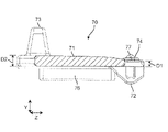
- the cover 70 has a cover body 71 and positioning projections 72 .
- the cover main body 71 has a substantially rectangular plate shape extending along the first surface 51 and extends from the center of the cover main body 71 toward the second guide projections 76 in the third direction X of the cover main body 71 .
- a positioning projection 72 is provided at an end portion 74 at a distant position and close to the second surface 52 in the first direction Z.
- the positioning protrusion 72 protrudes from the cover main body 71 toward the inside of the housing 50 along the second direction Y.
- the tip of the positioning projection 72 (in other words, one end in the second direction Y facing the positioning member 56 of the housing 50) is curved.
- the cover body 71 has a dimension D1 in the second direction Y at one end in the first direction Z (that is, the end 74) and a dimension D2 in the second direction Y at the other end in the first direction Z. is configured to be smaller than
- the cover 70 includes a first guide projection 75 provided at one end of a third direction X intersecting the first direction Z and the second direction Y of the cover body 71 and a third guide projection 75 of the cover body 71 . and a second guide projection 76 provided at the other end in the X direction.
- Each of the first guide protrusion 75 and the second guide protrusion 76 has, for example, a substantially rectangular plate shape and protrudes from the cover main body 71 toward the inside of the housing 50 along the second direction Y. As shown in FIG.
- the cover 70 has an operation portion 73 extending from the cover body 71 toward the outside of the housing 50 along the second direction Y.
- the operating portion 73 has, for example, a substantially truncated pyramid shape and is arranged at a position away from the center of the cover main body 71 toward the second guide projection 76 in the third direction X. .
- the cover 70 has a projecting portion 77 provided at one end of the cover body 71 in the first direction Z.
- the cover 70 has two protrusions 77 , and one protrusion 77 is arranged on each side of the positioning protrusion 72 in the third direction X.
- Each protruding portion 77 protrudes from the cover main body 71 toward the outside of the housing 50 along the second direction Y.
- each projecting portion 77 overlaps the portion around the opening 53 of the housing 50 when viewed along the first direction Z.
- the tip of each protrusion 77 (in other words, one end in the second direction Y facing the first surface 51 of the housing 50) is curved.
- the electronic device 1 can exhibit the following effects.
- the electronic device 1 includes the housing 50 , the electronic component 60 and the cover 70 .
- the housing 50 has a first surface 51 on which the display unit 11 is provided and a second surface 52 that intersects with the first surface 51, and in a first direction that intersects the second surface 52 of the first surface 51
- An opening 53 is provided between the display section 11 and the second surface 52 .
- the electronic component 60 is arranged inside the housing 50 and exposed to the outside of the housing 50 through the opening 53 .
- the cover 70 is arranged between the opening 53 and the electronic component 60 in the second direction intersecting the first surface 51, and the closed position P1 where the cover 70 closes the opening 53 and the cover 70 opens the opening 53. It moves along the first direction between the open positions P2. With such a configuration, the space required for moving the cover 70 can be reduced, and the space inside the housing 50 in which other electronic components can be mounted can be increased. As a result, an electronic device with a high degree of freedom in arranging the electronic components 60 can be realized.
- each electronic component 60 can be separated independently. can be exposed to the outside of the housing 50. As a result, it is possible to suppress the influence of other electronic components 60 due to the opening and closing of the opening 53 through which the electronic component 60 is exposed.
- the cover 70 has a cover body 71 extending along the first surface 51 and positioning projections 72 projecting from the cover body 71 toward the interior of the housing 50 along the second direction.
- the housing 50 is arranged inside the housing 50 relative to the cover main body 71 in the second direction, and a first recess 57 is provided to accommodate the positioning projection 72 when the cover 70 is positioned at the closed position P1. It has a positioning member 56 . With such a configuration, the cover 70 can be held in the closed position P1.
- a gap 81 is provided between the positioning protrusion 72 and the bottom of the first recess 57 when the cover 70 is positioned at the closed position P1.
- the cover 70 has a cover body 71 extending along the first surface 51 and positioning projections 72 projecting from the cover body 71 toward the interior of the housing 50 along the second direction.
- the housing 50 is arranged inside the housing 50 relative to the cover main body 71 in the second direction, and a second concave portion 58 is provided to accommodate the positioning protrusion 72 when the cover 70 is positioned at the open position P2. It has a positioning member 56 . With such a configuration, the cover 70 can be held at the open position P2.
- a gap 82 is provided between the positioning protrusion 72 and the bottom of the second recess 58 when the cover 70 is positioned at the open position P2.
- a positioning protrusion 72 is provided at one end of the cover body 71 in the first direction.
- the dimension in the second direction at one end of the cover body 71 in the first direction is smaller than the dimension in the second direction at the other end of the cover body 71 in the first direction.
- the cover 70 has first guide projections 75 and second guide projections 76 .
- the first guide protrusion 75 is provided at one end of the cover main body 71 in a third direction intersecting the first direction and the second direction, and protrudes from the cover main body 71 toward the inside of the housing 50 along the second direction.
- the second guide projection 76 is provided at the other end of the cover main body 71 in the third direction, and protrudes from the cover main body 71 toward the interior of the housing 50 along the second direction.
- the positioning member 56 has a first groove portion 561 and a second groove portion 562 .
- the first groove portion 561 is arranged to face the first guide projection 75 in the second direction and accommodates the first guide projection 75 .
- the second groove portion 562 is arranged to face the second guide projection 76 in the second direction and accommodates the second guide projection 76 .
- Each of first groove portion 561 and second groove portion 562 extends along the first direction to guide movement of cover 70 in the first direction. With such a configuration, the cover 70 can be moved more smoothly.
- the cover 70 has an operation portion 73 extending from the cover main body 71 toward the outside of the housing 50 along the second direction.
- the operating portion 73 is arranged at a position away from the center of the cover main body 71 in the third direction.
- the housing 50 has a first notch 54 and a second notch 55 provided on the first surface 51 .
- the first notch 54 is connected to the opening 53 from one side in the first direction with respect to the opening 53 and accommodates the operating portion 73 when the cover 70 is positioned at the closed position P1.
- the second notch 55 is connected to the opening 53 from the other side of the opening 53 in the first direction, and accommodates the operating portion 73 when the cover 70 is positioned at the open position P2.
- the cover 70 has a protrusion 77 provided at one end of the cover body 71 in the first direction.
- the protruding portion 77 protrudes from the cover body 71 toward the outside of the housing 50 along the second direction, and overlaps the portion around the opening 53 of the housing 50 when viewed along the first direction. there is Such a configuration can prevent the cover 70 from floating.
- the electronic device 1 can also be configured as follows.
- the electronic device 1 has an arbitrary configuration including a housing 50 provided with an opening 53, electronic components 60 exposed to the outside of the housing 50 through the opening 53, and a cover 70 opening and closing the opening 53.
- a housing 50 provided with an opening 53
- electronic components 60 exposed to the outside of the housing 50 through the opening 53
- a cover 70 opening and closing the opening 53 can be adopted.
- the operating portion 73 and the positioning projections 72 of the cover 70 and the positioning member 56 of the housing can be omitted.
- Either one or both of the first notch 54 and the second notch 55 of the housing 50 can be omitted.
- Either one or both of the first recess 57 and the second recess 58 of the positioning member 56 can be omitted.
- the first recess 57, the second recess 58 and the positioning projection 72 may be configured so that the gaps 81 and 82 are not formed when the cover 70 is positioned at the closed position P1 or the open position P2. That is, the inner surface of the first recessed portion 57 or the second recessed portion 58 and the outer shape of the positioning protrusion 72 may be substantially the same.
- the dimension of the cover body 71 in the second direction may be substantially uniform.
- first guide projections 75 and the second guide projections 76 of the cover 70 can be omitted.
- first groove portion 561 and the second groove portion 562 of the positioning member 56 can also be omitted.
- the projecting portion 77 of the cover 70 can be omitted.
- the present disclosure can be widely applied to electronic devices including notebook personal computers.
Landscapes
- Engineering & Computer Science (AREA)
- Computer Hardware Design (AREA)
- Theoretical Computer Science (AREA)
- General Engineering & Computer Science (AREA)
- Human Computer Interaction (AREA)
- Physics & Mathematics (AREA)
- General Physics & Mathematics (AREA)
- Microelectronics & Electronic Packaging (AREA)
- Casings For Electric Apparatus (AREA)
Priority Applications (5)
| Application Number | Priority Date | Filing Date | Title |
|---|---|---|---|
| EP22774910.8A EP4318176A4 (en) | 2021-03-24 | 2022-02-28 | ELECTRONIC DEVICE |
| CN202280023380.3A CN117099067A (zh) | 2021-03-24 | 2022-02-28 | 电子设备 |
| JP2023508848A JP7731039B2 (ja) | 2021-03-24 | 2022-02-28 | 電子機器 |
| US18/370,938 US12405633B2 (en) | 2021-03-24 | 2023-09-21 | Electronic device |
| US19/292,663 US20250362711A1 (en) | 2021-03-24 | 2025-08-06 | Electronic device |
Applications Claiming Priority (2)
| Application Number | Priority Date | Filing Date | Title |
|---|---|---|---|
| JP2021-050061 | 2021-03-24 | ||
| JP2021050061 | 2021-03-24 |
Related Child Applications (1)
| Application Number | Title | Priority Date | Filing Date |
|---|---|---|---|
| US18/370,938 Continuation US12405633B2 (en) | 2021-03-24 | 2023-09-21 | Electronic device |
Publications (1)
| Publication Number | Publication Date |
|---|---|
| WO2022202112A1 true WO2022202112A1 (ja) | 2022-09-29 |
Family
ID=83395542
Family Applications (1)
| Application Number | Title | Priority Date | Filing Date |
|---|---|---|---|
| PCT/JP2022/008126 Ceased WO2022202112A1 (ja) | 2021-03-24 | 2022-02-28 | 電子機器 |
Country Status (5)
| Country | Link |
|---|---|
| US (2) | US12405633B2 (https=) |
| EP (1) | EP4318176A4 (https=) |
| JP (1) | JP7731039B2 (https=) |
| CN (1) | CN117099067A (https=) |
| WO (1) | WO2022202112A1 (https=) |
Cited By (1)
| Publication number | Priority date | Publication date | Assignee | Title |
|---|---|---|---|---|
| JP7299550B1 (ja) | 2022-12-23 | 2023-06-28 | 富士通クライアントコンピューティング株式会社 | カメラシャッター構造 |
Citations (4)
| Publication number | Priority date | Publication date | Assignee | Title |
|---|---|---|---|---|
| JP2014085973A (ja) | 2012-10-25 | 2014-05-12 | Nec Personal Computers Ltd | 放熱装置及び携帯情報機器 |
| JP2018200669A (ja) * | 2017-11-01 | 2018-12-20 | 京セラ株式会社 | 電子機器 |
| JP2020113040A (ja) * | 2019-01-11 | 2020-07-27 | レノボ・シンガポール・プライベート・リミテッド | 電子機器 |
| JP2020201886A (ja) * | 2019-06-13 | 2020-12-17 | レノボ・シンガポール・プライベート・リミテッド | 電子機器 |
Family Cites Families (26)
| Publication number | Priority date | Publication date | Assignee | Title |
|---|---|---|---|---|
| US5199888A (en) * | 1992-01-24 | 1993-04-06 | Compaq Computer Corporation | Apparatus for covering the electrical connectors of a notebook computer |
| US5768163A (en) * | 1996-04-15 | 1998-06-16 | Hewlett-Packard | Versatile attachment of handheld devices to a host computing system |
| US5801919A (en) * | 1997-04-04 | 1998-09-01 | Gateway 2000, Inc. | Adjustably mounted camera assembly for portable computers |
| US6002581A (en) * | 1997-08-19 | 1999-12-14 | Gateway 2000, Inc. | Lap top computer system with elevating port cover |
| TW352206U (en) * | 1997-12-30 | 1999-02-01 | First Int Computer Inc | Structure for hidden type image picking apparatus of notebook computer |
| US6757160B2 (en) * | 2002-06-06 | 2004-06-29 | Hewlett-Packard Development Company, L.P. | Flexible door for use with an electronic device |
| JP2004040382A (ja) | 2002-07-02 | 2004-02-05 | Canon Inc | カメラ付き携帯情報端末 |
| US20040263666A1 (en) | 2003-04-21 | 2004-12-30 | Kiyoaki Tsuji | Lens barrier mechanism and image pickup apparatus |
| JP2004325519A (ja) | 2003-04-21 | 2004-11-18 | Sony Corp | レンズバリア機構及び撮像装置 |
| JP3938106B2 (ja) | 2003-06-24 | 2007-06-27 | ソニー株式会社 | レンズフード及び撮像装置 |
| US7048556B2 (en) * | 2003-12-04 | 2006-05-23 | Motorola, Inc. | Connector cover for communication device |
| TWI309346B (en) * | 2006-08-30 | 2009-05-01 | Asustek Comp Inc | Foldable electronic apparatus |
| US7850371B2 (en) * | 2008-11-25 | 2010-12-14 | Alcatel-Lucent Usa Inc. | Fiber optic cable interface cover and method of operating the same |
| JP2011065616A (ja) * | 2009-08-21 | 2011-03-31 | Sony Corp | 電子機器 |
| WO2011162754A1 (en) * | 2010-06-23 | 2011-12-29 | Hewlett-Packard Development Company, L.P. | Input/output port systems and methods |
| CN201781135U (zh) * | 2010-07-27 | 2011-03-30 | 国基电子(上海)有限公司 | 电子装置 |
| US9054444B2 (en) * | 2011-06-27 | 2015-06-09 | Hewlett-Packard Development Company, L.P. | Connector door for an electronic device |
| JP6028976B2 (ja) * | 2012-12-27 | 2016-11-24 | パナソニックIpマネジメント株式会社 | 電子機器 |
| US9465276B2 (en) * | 2013-07-06 | 2016-10-11 | Karl S Jonsson | Webcam privacy shield |
| US10187104B2 (en) * | 2014-07-28 | 2019-01-22 | Hewlett-Packard Development Company, L.P. | Protective jacket for a device |
| ITUB20160507A1 (it) * | 2016-01-26 | 2017-07-26 | Stefano Destefano | Dispositivo di protezione di un apparecchio elettronico |
| CN109714915A (zh) * | 2017-10-25 | 2019-05-03 | 杭州疆域创新医疗科技有限公司 | 开合结构及具有该开合结构的电子装置 |
| US10761404B2 (en) * | 2017-12-11 | 2020-09-01 | Handstands Promo, Llc | Privacy shutter for computer camera |
| WO2019156683A1 (en) * | 2018-02-12 | 2019-08-15 | Hewlett-Packard Development Company, L.P. | View shutters with slider magnets |
| US20210271856A1 (en) * | 2018-11-12 | 2021-09-02 | Hewlett-Packard Development Company, L.P. | Camera shutters with light filters |
| JP7752295B2 (ja) * | 2021-03-24 | 2025-10-10 | パナソニックIpマネジメント株式会社 | 電子機器 |
-
2022
- 2022-02-28 JP JP2023508848A patent/JP7731039B2/ja active Active
- 2022-02-28 EP EP22774910.8A patent/EP4318176A4/en active Pending
- 2022-02-28 WO PCT/JP2022/008126 patent/WO2022202112A1/ja not_active Ceased
- 2022-02-28 CN CN202280023380.3A patent/CN117099067A/zh active Pending
-
2023
- 2023-09-21 US US18/370,938 patent/US12405633B2/en active Active
-
2025
- 2025-08-06 US US19/292,663 patent/US20250362711A1/en active Pending
Patent Citations (4)
| Publication number | Priority date | Publication date | Assignee | Title |
|---|---|---|---|---|
| JP2014085973A (ja) | 2012-10-25 | 2014-05-12 | Nec Personal Computers Ltd | 放熱装置及び携帯情報機器 |
| JP2018200669A (ja) * | 2017-11-01 | 2018-12-20 | 京セラ株式会社 | 電子機器 |
| JP2020113040A (ja) * | 2019-01-11 | 2020-07-27 | レノボ・シンガポール・プライベート・リミテッド | 電子機器 |
| JP2020201886A (ja) * | 2019-06-13 | 2020-12-17 | レノボ・シンガポール・プライベート・リミテッド | 電子機器 |
Non-Patent Citations (1)
| Title |
|---|
| See also references of EP4318176A4 |
Cited By (2)
| Publication number | Priority date | Publication date | Assignee | Title |
|---|---|---|---|---|
| JP7299550B1 (ja) | 2022-12-23 | 2023-06-28 | 富士通クライアントコンピューティング株式会社 | カメラシャッター構造 |
| JP2024090474A (ja) * | 2022-12-23 | 2024-07-04 | 富士通クライアントコンピューティング株式会社 | カメラシャッター構造 |
Also Published As
| Publication number | Publication date |
|---|---|
| US20240012454A1 (en) | 2024-01-11 |
| JPWO2022202112A1 (https=) | 2022-09-29 |
| EP4318176A1 (en) | 2024-02-07 |
| EP4318176A4 (en) | 2024-08-21 |
| CN117099067A (zh) | 2023-11-21 |
| JP7731039B2 (ja) | 2025-08-29 |
| US12405633B2 (en) | 2025-09-02 |
| US20250362711A1 (en) | 2025-11-27 |
Similar Documents
| Publication | Publication Date | Title |
|---|---|---|
| CN108319331B (zh) | 便携式信息设备 | |
| US9600036B2 (en) | Hinge device for a portable computer | |
| US9645608B1 (en) | Portable electronic device | |
| US10747271B2 (en) | Dual-shaft hinge and electronic device | |
| JP6861343B2 (ja) | 電子機器 | |
| TW201944197A (zh) | 筆記型電腦 | |
| CN108345357A (zh) | 显示装置和电子设备 | |
| US20250362711A1 (en) | Electronic device | |
| KR20080006608A (ko) | 전자 장치용 힌지 구조 | |
| CN105321210A (zh) | 闸门结构与应用其的电子装置 | |
| JP7208553B1 (ja) | 電子機器 | |
| TWI676096B (zh) | 支撐裝置 | |
| CN110442189B (zh) | 笔记本电脑 | |
| JP7752295B2 (ja) | 電子機器 | |
| JP7759012B1 (ja) | 情報処理装置 | |
| US8755190B2 (en) | Housing of electronic device and electronic device | |
| US12235685B2 (en) | Electronic device | |
| JP7839976B2 (ja) | 電子機器 | |
| JP7784631B2 (ja) | 電子機器 | |
| TWM488837U (zh) | 電子裝置 | |
| JP6310231B2 (ja) | 付属部品一体型筐体 | |
| JP7692137B2 (ja) | 電子機器 | |
| TWM535282U (zh) | 電子裝置 | |
| WO2015097936A1 (ja) | 電子機器 | |
| JP5477905B2 (ja) | 照光装置及び電子機器 |
Legal Events
| Date | Code | Title | Description |
|---|---|---|---|
| 121 | Ep: the epo has been informed by wipo that ep was designated in this application |
Ref document number: 22774910 Country of ref document: EP Kind code of ref document: A1 |
|
| WWE | Wipo information: entry into national phase |
Ref document number: 2023508848 Country of ref document: JP |
|
| WWE | Wipo information: entry into national phase |
Ref document number: 202280023380.3 Country of ref document: CN |
|
| WWE | Wipo information: entry into national phase |
Ref document number: 2022774910 Country of ref document: EP |
|
| NENP | Non-entry into the national phase |
Ref country code: DE |
|
| ENP | Entry into the national phase |
Ref document number: 2022774910 Country of ref document: EP Effective date: 20231024 |