WO2022201866A1 - 膜ろ過装置、濃縮装置及び濃縮方法 - Google Patents
膜ろ過装置、濃縮装置及び濃縮方法 Download PDFInfo
- Publication number
- WO2022201866A1 WO2022201866A1 PCT/JP2022/003673 JP2022003673W WO2022201866A1 WO 2022201866 A1 WO2022201866 A1 WO 2022201866A1 JP 2022003673 W JP2022003673 W JP 2022003673W WO 2022201866 A1 WO2022201866 A1 WO 2022201866A1
- Authority
- WO
- WIPO (PCT)
- Prior art keywords
- filtration device
- membrane
- membrane filtration
- sample water
- pipe
- Prior art date
- Legal status (The legal status is an assumption and is not a legal conclusion. Google has not performed a legal analysis and makes no representation as to the accuracy of the status listed.)
- Ceased
Links
Images





Classifications
-
- C—CHEMISTRY; METALLURGY
- C12—BIOCHEMISTRY; BEER; SPIRITS; WINE; VINEGAR; MICROBIOLOGY; ENZYMOLOGY; MUTATION OR GENETIC ENGINEERING
- C12N—MICROORGANISMS OR ENZYMES; COMPOSITIONS THEREOF; PROPAGATING, PRESERVING, OR MAINTAINING MICROORGANISMS; MUTATION OR GENETIC ENGINEERING; CULTURE MEDIA
- C12N7/00—Viruses; Bacteriophages; Compositions thereof; Preparation or purification thereof
- C12N7/02—Recovery or purification
-
- B—PERFORMING OPERATIONS; TRANSPORTING
- B01—PHYSICAL OR CHEMICAL PROCESSES OR APPARATUS IN GENERAL
- B01D—SEPARATION
- B01D65/00—Accessories or auxiliary operations, in general, for separation processes or apparatus using semi-permeable membranes
- B01D65/02—Membrane cleaning or sterilisation ; Membrane regeneration
- B01D65/06—Membrane cleaning or sterilisation ; Membrane regeneration with special washing compositions
-
- B—PERFORMING OPERATIONS; TRANSPORTING
- B01—PHYSICAL OR CHEMICAL PROCESSES OR APPARATUS IN GENERAL
- B01D—SEPARATION
- B01D69/00—Semi-permeable membranes for separation processes or apparatus characterised by their form, structure or properties; Manufacturing processes specially adapted therefor
- B01D69/02—Semi-permeable membranes for separation processes or apparatus characterised by their form, structure or properties; Manufacturing processes specially adapted therefor characterised by their properties
-
- C—CHEMISTRY; METALLURGY
- C02—TREATMENT OF WATER, WASTE WATER, SEWAGE, OR SLUDGE
- C02F—TREATMENT OF WATER, WASTE WATER, SEWAGE, OR SLUDGE
- C02F1/00—Treatment of water, waste water, or sewage
- C02F1/44—Treatment of water, waste water, or sewage by dialysis, osmosis or reverse osmosis
-
- C—CHEMISTRY; METALLURGY
- C12—BIOCHEMISTRY; BEER; SPIRITS; WINE; VINEGAR; MICROBIOLOGY; ENZYMOLOGY; MUTATION OR GENETIC ENGINEERING
- C12M—APPARATUS FOR ENZYMOLOGY OR MICROBIOLOGY; APPARATUS FOR CULTURING MICROORGANISMS FOR PRODUCING BIOMASS, FOR GROWING CELLS OR FOR OBTAINING FERMENTATION OR METABOLIC PRODUCTS, i.e. BIOREACTORS OR FERMENTERS
- C12M1/00—Apparatus for enzymology or microbiology
- C12M1/12—Apparatus for enzymology or microbiology with sterilisation, filtration or dialysis means
-
- C—CHEMISTRY; METALLURGY
- C12—BIOCHEMISTRY; BEER; SPIRITS; WINE; VINEGAR; MICROBIOLOGY; ENZYMOLOGY; MUTATION OR GENETIC ENGINEERING
- C12N—MICROORGANISMS OR ENZYMES; COMPOSITIONS THEREOF; PROPAGATING, PRESERVING, OR MAINTAINING MICROORGANISMS; MUTATION OR GENETIC ENGINEERING; CULTURE MEDIA
- C12N1/00—Microorganisms; Compositions thereof; Processes of propagating, maintaining or preserving microorganisms or compositions thereof; Processes of preparing or isolating a composition containing a microorganism; Culture media therefor
-
- B—PERFORMING OPERATIONS; TRANSPORTING
- B01—PHYSICAL OR CHEMICAL PROCESSES OR APPARATUS IN GENERAL
- B01D—SEPARATION
- B01D2321/00—Details relating to membrane cleaning, regeneration, sterilization or to the prevention of fouling
- B01D2321/16—Use of chemical agents
- B01D2321/162—Use of acids
-
- B—PERFORMING OPERATIONS; TRANSPORTING
- B01—PHYSICAL OR CHEMICAL PROCESSES OR APPARATUS IN GENERAL
- B01D—SEPARATION
- B01D2321/00—Details relating to membrane cleaning, regeneration, sterilization or to the prevention of fouling
- B01D2321/16—Use of chemical agents
- B01D2321/164—Use of bases
-
- B—PERFORMING OPERATIONS; TRANSPORTING
- B01—PHYSICAL OR CHEMICAL PROCESSES OR APPARATUS IN GENERAL
- B01D—SEPARATION
- B01D2325/00—Details relating to properties of membranes
- B01D2325/02—Details relating to pores or porosity of the membranes
- B01D2325/0283—Pore size
-
- B—PERFORMING OPERATIONS; TRANSPORTING
- B01—PHYSICAL OR CHEMICAL PROCESSES OR APPARATUS IN GENERAL
- B01D—SEPARATION
- B01D2325/00—Details relating to properties of membranes
- B01D2325/14—Membrane materials having negatively charged functional groups
-
- B—PERFORMING OPERATIONS; TRANSPORTING
- B01—PHYSICAL OR CHEMICAL PROCESSES OR APPARATUS IN GENERAL
- B01D—SEPARATION
- B01D2325/00—Details relating to properties of membranes
- B01D2325/26—Electrical properties
-
- B—PERFORMING OPERATIONS; TRANSPORTING
- B01—PHYSICAL OR CHEMICAL PROCESSES OR APPARATUS IN GENERAL
- B01D—SEPARATION
- B01D2325/00—Details relating to properties of membranes
- B01D2325/30—Chemical resistance
Definitions
- the present disclosure relates to a membrane filtration device, a concentration device, and a concentration method.
- Patent Document 1 describes environmental water such as river water, lake water, seawater, and rainwater, drinking water such as well water, tap water, and bottled water, sewage, drainage, pool water, agricultural water, industrial water, and refrigerant water.
- a method of producing a purified virus solution from a sample solution such as industrial water, etc., concentrating the produced purified virus solution by a negative charge membrane method or the like, extracting nucleic acids, and detecting viruses is described.
- An object of the present disclosure is to provide a membrane filtration device, a concentration device, and a concentration method that can improve the convenience of treatment by the negative charge membrane method.
- a membrane filtration device includes a membrane that is made of an acid-resistant material, has pores with a pore size capable of trapping microorganisms, and has a surface that is negatively charged in a neutral to alkaline range.
- the membrane filtration device can be reused by performing cleaning with a strong acid after performing treatment by the negative charge membrane method using the membrane filtration device.
- the labor and time required to replace the filtration membrane can be reduced, and the cost of purchasing the negatively charged membrane for replacement and the time required to obtain the membrane after purchase can be reduced, increasing convenience.
- the membrane may be composed of an acid-resistant material that can withstand pH 2 or less. This allows the membrane to be washed with a strong acid solution to dissolve the microbial material.
- the membrane filtration device may further include a pressure vessel having pressure resistance, and the membrane may be held in the pressure vessel.
- a concentrating device includes the above-described membrane filtration device, a sample water supply unit arranged upstream of the membrane filtration device to supply sample water, and a sample water supply unit arranged upstream of the membrane filtration device.
- an acidic solution storage tank arranged in parallel with the water supply unit to store the acidic solution; and an acidic solution storage tank arranged in parallel with the sample water supply unit and the acidic solution storage tank on the upstream side of the membrane filtration device to store the alkaline solution.
- a cleaning solution discharge pipe for discharging the cleaning solution may be further provided on the downstream side of the membrane filtration device. This allows the strong acid cleaning solution to be properly discharged.
- a concentration method is a membrane filtration device comprising a membrane made of an acid-resistant material, having pores with a pore size capable of trapping microorganisms, and having a negatively charged surface in a neutral to alkaline range.
- a sample water supply unit arranged upstream of the membrane filtration device to supply sample water; and an acidic solution arranged in parallel with the sample water supply unit upstream of the membrane filtration device and storing an acidic solution.
- a concentration method performed by a concentrating device comprising: an outlet arranged downstream for discharging a fluid to the outside; and a recovery container arranged in parallel with the outlet downstream of the membrane filtration device for recovering the fluid.
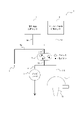
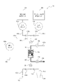
- FIG. 2 is a schematic configuration diagram of a purifier according to a comparative example, which purifies a virus particle concentrate from sample water.
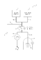
- FIG. 2 is a schematic diagram for explaining the processing procedure of the negative charge film method performed by the equipment of FIG. 1;
- FIG. 2 is a schematic diagram for explaining the processing procedure of the negative charge film method performed by the equipment of FIG. 1;
- FIG. 2 is a schematic diagram for explaining the processing procedure of the negative charge film method performed by the equipment of FIG. 1;
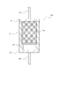
- 1 is a schematic configuration diagram of a membrane filtration device according to an embodiment of the present disclosure;
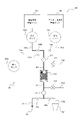
- FIG. 1 is a schematic configuration diagram of a concentrator according to an embodiment of the present disclosure;
- FIG. 7 is a schematic diagram for explaining the first step of the negative charge film process performed by the concentrator of FIG. 6;
- FIG. 7 is a schematic diagram for explaining the second step of the negative charge film process performed by the concentrator of FIG. 6;
- FIG. 7 is a schematic diagram for explaining the third step of the negative charge membrane process performed by the concentrator of FIG. 6;
- FIG. 7 is a schematic diagram for explaining the fourth step of the negative charge film process performed by the concentrator of FIG. 6;
- the negative charge membrane method is an example of a process that is performed for the purpose of purifying a concentrated liquid with an increased virus concentration by concentrating viruses from sample water.
- Microorganisms including bacteria and viruses have the property of being negatively charged in neutral to alkaline water areas. Since the sample water to be treated by the negative charge membrane method is neutral to alkaline, these microorganisms are negatively charged in the sample water.
- virus can be any known virus.
- Viruses may include, for example, double-stranded DNA viruses, single-stranded DNA viruses, double-stranded RNA viruses, single-stranded RNA viruses, single-stranded RNA reverse transcription viruses, or double-stranded DNA reverse transcription viruses.
- FIG. 1 is a schematic configuration diagram for explaining a comparative example of equipment capable of performing the process of the negative charge film method.
- the equipment 1 according to the comparative example includes a negative charge film 2 , an aspirator 3 and a suction bottle 4 .
- the solid lines connecting each component indicate piping through which the fluid flows.
- the negatively charged membrane 2 is a negatively charged membrane, and for example, a mixed cellulose membrane manufactured by Millipore (hereinafter also simply referred to as "HA membrane") can be used.
- the mixed cellulose membrane is, for example, a mixed membrane of nitrocellulose and cellulose acetate.
- the negatively charged membrane 2 is provided with pores capable of capturing viruses and permeable to molecules constituting the fluid such as water molecules. The diameter of the pores of the negatively charged membrane 2 may be appropriately determined according to the virus or the like to be captured by the negatively charged membrane 2 .
- a pipe 5 for supplying fluid is provided on the upstream side of the negative charge film 2 .
- three different pipes 5a, 5b, and 5c are manually connected to the pipe 5 for each procedure, so that different fluids are supplied to the negative charge film 2 via the pipe 5.
- different fluids may be supplied to the negative charge film 2 via the pipe 5 by changing the solution introduced into the pipe 5 .
- the first pipe 5a is a pipe that connects the pipe 5 and the sample water supply port 6.
- Sample water that may contain viruses is supplied from the sample water supply port 6 to the first pipe 5a.
- the given solution may be, for example, a magnesium chloride solution.
- the viruses contained in the sample water are aggregated and easily captured by the negatively charged membrane 2 .
- An appropriate solution may be used as the predetermined solution depending on the properties of the sample water. Also, the predetermined solution may not be used depending on the properties of the sample water.
- the second pipe 5b is a pipe that connects the pipe 5 and the acidic solution storage tank 7 in which the acidic aqueous solution is stored.
- An acidic aqueous solution is supplied from the acidic solution storage tank 7 to the second pipe 5b.
- the acidic aqueous solution is described as being a sulfuric acid solution as an example, but is not limited to this.
- the third pipe 5c is a pipe that connects the pipe 5 and an alkaline solution storage tank 8 in which an alkaline aqueous solution is stored.
- An alkaline aqueous solution is supplied from the alkaline solution storage tank 8 to the third pipe 5c.
- the alkaline aqueous solution is described as being an aqueous sodium hydroxide solution as an example, but is not limited to this.
- a fluid is supplied to the negative charge film 2 via the pipe 5 from each of the three pipes 5a, 5b and 5c connected in each procedure. Only one of the sample water, the acidic aqueous solution, and the alkaline aqueous solution is supplied to the negative charge film 2 at the same timing. That is, the pipes 5a, 5b, and 5c are manually reconnected for each procedure so that two or more of the sample water, acidic aqueous solution, and alkaline aqueous solution are not supplied at the same timing.
- the aspirator 3 is arranged downstream with respect to the negative charge film 2 .
- the aspirator 3 draws the fluid supplied to the negatively charged membrane 2 by creating a reduced pressure.
- the aspirator 3 is driven, the fluid is drawn into the aspirator 3 and discharged to the outside.
- the suction bottle 4 is arranged downstream with respect to the negative charge film 2 and arranged in parallel with the aspirator 3 .
- the suction bottle 4 draws in the fluid supplied to the negatively charged membrane 2 by creating a reduced pressure state, and recovers the fluid in the concentrated liquid recovery container 10 provided inside.
- the fluid is drawn into the suction bottle 4 and collected in the concentrated liquid collection container 10 .
- FIGS. 2 to 4 are schematic diagrams for explaining the processing procedure of the negative charge film method performed by the equipment 1 of FIG.
- the thick lines in FIGS. 2 to 4 represent fluid flow.
- a case where the sample water to be filtered has a small volume of, for example, 2 liters or less will be described.
- a flat film is used as the negative charge film 2 .
- the sample water flows from the sample water supply port 6 through the first pipe 5a to the negative charge film 2 as shown in FIG. supplied to
- the positive ions contained in the sample water are captured by the negative charge film 2 because they are positively charged.
- Viruses contained in the sample water are captured by the negatively charged membrane 2 because they are larger than the pores of the negatively charged membrane 2 .
- a membrane capable of trapping the virus is used as the negatively charged membrane 2 .
- an HA membrane with a pore size of 0.45 ⁇ m and a diameter of 13-90 mm can be used as the negative charge membrane 2 .
- the sample water in which cations and viruses have been captured is drained by an aspirator 3 through pipes 11 and 11a arranged downstream of the negatively charged membrane 2 .
- the second pipe 5b is connected to the pipe 5 in place of the first pipe 5a, and the aspirator 3 is driven so that sulfuric acid is discharged from the acidic solution storage tank 7 through the second pipe 5b as shown in FIG.
- a solution is supplied to the negatively charged membrane 2 .
- the negative charge film 2 is washed with acid. That is, by supplying the sulfuric acid solution to the negative charge film 2 and flowing it downstream with the aspirator 3, the cations captured by the negative charge film 2 are eluted from the negative charge film 2 and flowed through the pipes 11 and 11a together with the sulfuric acid solution. drained.
- the sulfuric acid solution can be anything that can be acid washed, for example, a 0.5 mM sulfuric acid solution at pH 3.0 can be used. Also, the sulfuric acid solution may be supplied in an appropriate amount, for example, the volume of the supplied sample water may be 1/10 or less. Viruses remain attached to the negatively charged film 2 by the acid cleaning.
- a third pipe 5c is connected to the pipe 5 in place of the second pipe 5b, and as shown in FIG. be done.
- the negatively charged virus captured by the negatively charged membrane 2 is eluted from the negatively charged membrane 2 and flows together with the sodium hydroxide aqueous solution through the pipes 11 and 11b into the suction bottle 4, whereupon the concentrated liquid collection container Collected at 10.
- Any aqueous sodium hydroxide solution that can recover viruses can be used.
- a 1.0 mM aqueous sodium hydroxide solution at pH 10.5-10.8 can be used.
- the sodium hydroxide aqueous solution may be supplied in an appropriate amount, for example, 1 to 10 ml. The smaller the amount of aqueous sodium hydroxide solution to be supplied, the higher the virus concentration effect, which is preferable.
- the concentrate collection container 10 preferably contains 5-50 ⁇ l of 0.2 N sulfuric acid solution and 10-100 ⁇ l of pH 8.0 buffer in advance.
- viruses in sample water can be purified in the concentrated liquid collection container 10 by performing the negative charge film method in the facility 1 by the processing described with reference to FIGS. 2 to 4 .
- the volume of sample water to be filtered is large, for example exceeding 2 liters, it is preferable to carry out two-stage concentration using the negatively charged membrane 2 .
- a housing-shaped membrane is used as the negative charge membrane 2 .
- the two-stage concentration in the primary concentration step of the first stage, for example, an HA membrane with a pore size of 0.45 ⁇ m and a diameter of 293 mm, or a cartridge type filter, Opticap XL2 manufactured by Millipore, is used as the negative charge membrane 2, Concentration is performed as described with reference to FIGS.
- a magnesium chloride solution is added to the primary concentrate purified in the temporary concentration step in order to allow the viruses in the concentrated solution purified in the temporary concentration step to adsorb cations.
- the molar concentration and volume of the magnesium chloride solution to be added can be appropriately determined based on the volume of the sample water or the temporary concentrate. For example, 4.0 ml of 2.5 M magnesium chloride solution may be added.
- a second stage of secondary concentration is then performed. In the secondary concentration step, the temporary concentrated liquid to which the magnesium chloride solution has been added is subjected to the treatment described with reference to FIGS. 2 to 4. FIG. Thus, a two-stage concentration is performed.
- a mixed cellulose film of nitrocellulose and cellulose acetate is generally used as the negative charge film 2 .
- This negatively charged membrane 2 is replaced each time filtration is performed in order to ensure filtration performance.
- it since it is necessary to replace the negative charge film 2 manually, it takes time and effort.
- the cost of purchasing the negative charge film 2 for replacement and the time from purchase to acquisition are also required.
- the filtration volume of the sample water that can be filtered is greatly reduced when a flat membrane is used and raw sewage water with a high concentration of turbidity and impurities is used as the sample water. That is, when filtering sample water with a high turbidity load, the filtration resistance in the negative charge membrane 2 increases according to the amount of permeated water, and a situation may arise in which sufficient filtration driving force cannot be secured by suction.
- a membrane filtration device, a concentration device, and a concentration method that can solve the above problems will be described below.
- FIG. 5 is a schematic configuration diagram of the membrane filtration device 110 according to one embodiment of the present disclosure.
- a membrane filtration device 110 shown in FIG. 5 is used in a concentration device 100 which will be described later.
- the membrane filtration device 110 comprises a pressure vessel 111, a casing 112, a membrane 113, an upstream lid 114 and a downstream lid 115.
- the pressure vessel 111 is a vessel having a predetermined pressure resistance.
- the pressure vessel 111 has a pressure resistance of 0 to 0.49 MPa, for example.
- the pressure resistance of the pressure vessel 111 is not limited to this, and the pressure vessel 111 having an appropriate pressure resistance may be used depending on the specifications of the concentrator 100 or the like.
- the pressure vessel 111 may, for example, be configured cylindrically.
- the pressure vessel 111 holds a casing 112 inside.
- the casing 112 is, for example, cylindrical and held by the pressure vessel 111 .
- the casing 112 is a casing for fixing the membrane 113 on the downstream side, and fixes the membrane 113 from the upstream side.
- the casing 112 may be made of a material such as glass, polypropylene, or fluororesin, but is not limited to these and may be made of other appropriate materials.
- Membrane 113 is held inside pressure vessel 111 and fixed downstream of casing 112 by casing 112 .
- Membrane 113 is a virus trapping membrane.
- the membrane 113 is capable of membrane filtration at about pH 3, and the surface charge of the membrane 113 is preferably negative to near the isoelectric point.
- About pH 3 includes, for example, the range of pH 2.5 to 3.5.
- Membrane 113 is capable of membrane filtration in the neutral to alkaline range.
- the neutral to alkaline range is, for example, a range of pH 6 or higher.
- the membrane 113 has a negative surface charge in the neutral to alkaline range. This allows the film 113 to function as a negatively charged film in the neutral to alkaline range.
- the film 113 is composed of an acid-resistant material. It is particularly preferable that the film 113 be made of an acid-resistant material that can withstand pH 2 or less. As a result, when the membrane filtration device 110 is washed with a strong acid solution as described later, it is less likely to be eroded by the strong acid solution, and the chargeability is not deteriorated even if washing with a cleaning solution is performed as described later.
- the membrane 113 may be composed of an organic membrane material such as polyethylene, tetrafluoroethylene, polypropylene, cellulose acetate, polyacrylonitrile, polyimide, polysulfone, or polyethersulfone, for example.
- the film 113 may be composed of a ceramic film using aluminum oxide, zirconium oxide, titanium oxide, or the like, or an inorganic film material such as stainless steel or glass.
- the membrane 113 has pores with an appropriate pore size capable of capturing viruses.
- Membrane 113 may have pores with a pore size of 0.1-2 ⁇ m, for example.
- Membrane 113 may be a microfiltration membrane.
- Membrane 113 may be flat membrane shaped or housing shaped.
- the membrane 113 may consist of a cartridge type filter.
- the pressure vessel 111 and the casing 112 have appropriate dimensions and shapes according to the shape and diameter of the membrane 113 and the like.
- the membrane filtration device 110 may include a jig for fixing the membrane 113 to the pressure vessel 111 on the downstream side of the membrane 113 .
- the jig has a mesh or porous structure.
- the upstream lid 114 and the downstream lid 115 are lids that cover the upstream side and the downstream side of the pressure vessel 111, respectively.
- the upstream lid 114 and the downstream lid 115 have pressure resistance.
- the upstream lid 114 and the downstream lid 115 can be secured to the pressure vessel 111 in any manner, for example screwed or jigged.
- upstream side piping 101 is connected to the upstream side of membrane filtration device 110 .
- a downstream pipe 105 is connected to the downstream side of the membrane filtration device 110 .
- the sample water is supplied from the upstream pipe 101 to the membrane filtration device 110, the sample water is filtered by catching viruses on the membrane 113 of the membrane filtration device 110, and the filtered permeated water is sent downstream. It is discharged from the side pipe 105 .
- the discharge is performed, for example, by being sucked by a suction pump provided on the downstream side of the downstream pipe 105 .
- FIG. 6 is a schematic configuration diagram of the concentrator 100 according to one embodiment of the present disclosure.
- the concentrator 100 includes a membrane filtration device 110, a first pump 103a, a second pump 103b, a third pump 103c, and a concentrate recovery container 104.
- a solid line connecting each component indicates a pipe through which a fluid flows.
- An upstream pipe 101 for supplying fluid is provided on the upstream side of the membrane filtration device 110 .
- a cleaning solution supply pipe 102 a for supplying a solution for cleaning the membrane filtration device 110 is branched and connected to the upstream pipe 101 .
- the upstream pipe 101 is provided with a first sluice valve 121 that controls the fluid supply route upstream of the branch point with the cleaning solution supply pipe 102a.
- the cleaning solution supply pipe 102 a is provided with a second gate valve 122 that controls the supply route of the cleaning solution to the membrane filtration device 110 .
- a cleaning solution storage tank (not shown) that stores the cleaning solution is provided on the upstream side of the cleaning solution supply pipe 102a.
- Three different pipes 101a, 111b, and 111c are connected to the upstream pipe 101 upstream of the first gate valve 121, and different fluids flow upstream from these three pipes 101a, 111b, and 111c. It is supplied to the membrane filtration device 110 via the side pipe 101 .
- the first pipe 101 a is a pipe that connects the upstream pipe 101 and the sample water supply unit 106 .
- Sample water that may contain viruses is supplied from the sample water supply unit 106 to the first pipe 101a.
- the sample water supply unit 106 may supply a solution obtained by mixing sample water sampled from water treatment infrastructure facilities with a predetermined solution in the same manner as described in the comparative example.
- a given solution is a magnesium chloride solution. By mixing the magnesium chloride solution, the virus contained in the sample water is aggregated and easily captured by the membrane 113 .
- a valve 109a is provided in the first pipe 101a. The supply of sample water from the first pipe 101a is controlled by opening and closing the valve 109a.
- a first pump 103a is provided on the first pipe 101a.
- the first pump 103a feeds sample water from the sample water supply unit 106 to the downstream side.
- the first pump 103a may be a pressure pump.
- the load on the membrane filtration device 110 is high. is preferably used.
- a pressurizing pump By using a pressurizing pump, the sample water is supplied with a stronger pressure, and it becomes easier to prevent sedimentation of turbidity and insoluble substances in the piping.
- a pressure pump as the first pump 103a.
- sample water can be supplied under a stronger pressure, and the time required for filtration can be shortened.
- the second pipe 101 b is a pipe that connects the upstream pipe 101 and the acidic solution storage tank 107 .
- the acidic solution storage tank 107 is a tank that stores an acidic aqueous solution (acidic solution).
- the acidic aqueous solution is described as being a sulfuric acid solution as an example, but is not limited to this.
- a valve 109b is provided on the second pipe 101b. The supply of the acidic solution from the second pipe 101b is controlled by opening and closing the valve 109b.
- a second pump 103b is provided on the second pipe 101b.
- the second pump 103b sends the acidic solution from the acidic solution storage tank 107 to the downstream side.
- the second pump 103b may be a pressure pump.
- the third pipe 101 c is a pipe that connects the upstream pipe 101 and the alkaline solution storage tank 108 .
- the alkaline solution storage tank 108 is a tank that stores an alkaline aqueous solution (alkaline solution).
- alkaline aqueous solution is described as being an aqueous sodium hydroxide solution as an example, but is not limited to this.
- a valve 109c is provided on the third pipe 101c. The supply of the alkaline solution from the third pipe 101c is controlled by opening and closing the valve 109c.
- a third pump 103c is provided on the third pipe 101c.
- the third pump 103c sends the alkaline solution from the alkaline solution storage tank 108 to the downstream side.
- the third pump 103c may be a pressure pump.
- the membrane filtration device 110 is the membrane filtration device 110 described with reference to FIG.
- the membrane filtration device 110 may include, for example, a flat membrane with a diameter of about 10 mm as the membrane 113 .
- a downstream pipe 105 for discharging the fluid that has passed through the membrane filtration device 110 is provided on the downstream side of the membrane filtration device 110 .
- a cleaning solution discharge pipe 102 b for discharging the cleaning solution used for cleaning the membrane filtration device 110 is branched and connected to the downstream pipe 105 .
- the downstream pipe 105 is provided with a third sluice valve 123 that controls the fluid discharge path downstream of the branch point with the cleaning solution discharge pipe 102b.
- the cleaning solution discharge pipe 102b is provided with a fourth gate valve 124 for controlling the discharge route of the cleaning solution.
- a cleaning solution recovery tank (not shown) for recovering the cleaning solution discharged from the membrane filtration device 110 may be provided downstream of the cleaning solution discharge pipe 102b.
- Two different pipes 105 a and 105 b are connected to the downstream pipe 105 downstream of the third gate valve 123 .
- the fourth pipe 105a communicates with the discharge port 125 and discharges the fluid from the discharge port 125.
- a valve 109d is provided on the fourth pipe 105a. The discharge of the fluid from the fourth pipe 105a is controlled by opening and closing the valve 109d.
- the fifth pipe 105 b is a pipe that connects the downstream pipe 105 and the concentrated liquid recovery container 104 .
- the concentrate collection container 104 is a container for collecting the virus concentrate.
- a valve 109e is provided on the fifth pipe 105b. By opening and closing the valve 109e, the transfer of the concentrated liquid from the fifth pipe 105b to the concentrated liquid recovery container 104 is controlled.
- Each component of the concentrator 100 has a predetermined pressure resistance, for example, 0.49 MPa. Further, the driving pressure in the concentrator 100 is determined based on the pressure resistance of the membrane 113 of the membrane filtration device 110, and can be set to 0.3 MPa at maximum, for example. The driving pressure is the difference between the sample water supply pressure to the membrane filtration device 110 and the permeation pressure of the sample water that has passed through the membrane filtration device 110 .
- FIG. 7 to 10 are schematic diagrams for explaining each step of the negative charge film process performed by the concentrator 100.
- FIG. The thick lines in FIGS. 7 to 10 represent fluid flow.
- purification of the virus particle concentrate is performed by the negative charge membrane method in the first to third steps, and the membrane 113 provided in the membrane filtration device 110 is washed in the fourth step.
- FIG. 7 is a schematic diagram for explaining the first step of the negative charge membrane process performed by the concentrator 100 of FIG.
- the first step is a step of filtering sample water.
- the valves 109a and 109d, the first gate valve 121 and the third gate valve 123 are opened, and the valves 109b, 109c and 109e, the second gate valve 122 and the fourth gate valve 124 are closed. state.
- sample water that may contain viruses is supplied from the sample water supply unit 106 to the membrane filtration device 110 via the first pipe 101 a and the upstream pipe 101 .
- the sample water supplied to the membrane filtration device 110 is filtered by the membrane 113 of the membrane filtration device 110 . That is, since the cations contained in the sample water are positively charged, they are captured by the negatively charged membrane 113 . Viruses contained in the sample water are captured by the membrane 113 because they are larger than the pores of the membrane 113 .
- the sample water filtered by the membrane 113 is drained through the downstream pipe 105 and the fourth pipe 105a.
- Filtration in the first step may be performed, for example, for a few seconds to an hour.
- the sample water may be sent downstream by the first pump 103a.
- the driving pressure of the first pump 103 a may be appropriately adjusted within the allowable pressure range of the concentrator 100 . The higher the driving pressure of the first pump 103a, the shorter the time required for filtering in the first step.
- the sample water may be sent downstream by a decompression pump instead of the pressurization first pump 103a.
- the pressure reducing pump is arranged downstream of the membrane filtration device 110 .
- the sample water may be sent downstream by applying pressure using a pressure water tank.
- the time required for the first step filtration is also shortened when a decompression pump or pressure water bath is used.
- the filtration resistance in the membrane 113 increases according to the time required for filtration or the amount of sample water to be filtered. Water volume can be reduced.
- the driving pressure of the pump or pressure water tank may be increased, for example, depending on the time required or the amount of sample water filtered.
- the filtration resistance gradually increases.
- the driving pressure of the pump or pressure water tank may be gradually increased.
- FIG. 8 is a schematic diagram for explaining the second step of the negative charge membrane process performed by the concentrator 100 of FIG. The second step is to acid wash the film 113 .
- the valves 109b and 109d, the first gate valve 121 and the third gate valve 123 are opened, and the valves 109a, 109c and 109e, the second gate valve 122 and the fourth gate valve 124 are closed. state.
- the sulfuric acid solution is supplied from the acidic solution storage tank 107 through the second pipe 101b and the upstream pipe 101 to the membrane filtration device 110, and the membrane 113 is washed with acid.
- the cations captured by the membrane 113 in the first step are eluted from the membrane 113 and drained together with the sulfuric acid solution through the downstream pipe 105 and the fourth pipe 105a. In this manner, cations are removed from membrane 113 .
- the sulfuric acid solution may be, for example, a 0.5 mM sulfuric acid solution at pH 3.0.
- the amount of sulfuric acid solution to be supplied is preferably such that the entire surface of the membrane 113 is evenly contacted with the sulfuric acid solution.
- the amount of sulfuric acid solution supplied may be one-tenth the volume of the sample water, or 10 mL or more.
- the amount of sulfuric acid solution supplied may be one-tenth the volume of the sample water.
- the concentrator 100 may be provided with a valve downstream of the membrane 113 so that the time or state of contact and immersion between the sulfuric acid solution and the membrane can be controlled.
- the supply of the sulfuric acid solution can be controlled so that the sulfuric acid solution is evenly spread over the membrane surface by several millimeters. preferable.
- the membrane 113 has a housing shape, it is preferable to control the supply of the sulfuric acid solution so that the sulfuric acid solution is spread on the upstream side of the membrane filtration device 110 .
- the membrane 113 is preferably immersed in the sulfuric acid solution for several seconds or more. As a result, the amount of cations remaining in the film 113 can be reduced, and more appropriate acid cleaning can be performed.
- FIG. 9 is a schematic diagram for explaining the third step of the negative charge membrane process performed by the concentrator 100 of FIG.
- the third step is to purify the virus concentrate by alkaline elution.
- the valves 109c and 109e, the first gate valve 121 and the third gate valve 123 are opened, and the valves 109a, 109b and 109d, the second gate valve 122 and the fourth gate valve 124 are closed. state.
- the sodium hydroxide aqueous solution is supplied from the alkaline solution storage tank 108 to the membrane filtration device 110 via the third pipe 101c and the upstream pipe 101, and the alkali Elution is performed. That is, the virus captured by the membrane 113 in the first step is eluted from the membrane 113 and flows downstream through the downstream pipe 105 and the fifth pipe 105b together with the sodium hydroxide aqueous solution, and the virus concentrate is concentrated. It is collected in the liquid collection container 104 .
- sodium hydroxide aqueous solution for example, a 1.0 mM sodium hydroxide aqueous solution having a pH of 10.5 to 10.8 can be used.
- the supplied sodium hydroxide aqueous solution may be, for example, 10 ml or more.
- the smaller the amount of the aqueous sodium hydroxide solution to be supplied the higher the effect of concentrating the virus, which is preferable.
- the concentrator 100 may be provided with a valve downstream of the membrane 113 so that the time or state of contact and immersion between the aqueous sodium hydroxide solution and the membrane can be controlled.
- the sodium hydroxide aqueous solution is fed so that the sodium hydroxide aqueous solution is evenly spread on the membrane surface by several millimeters. Liquid control is preferred.
- the membrane 113 has a housing shape, it is preferable to control the feeding of the aqueous sodium hydroxide solution so that the aqueous sodium hydroxide solution is spread on the upstream side of the membrane filtration device 110 .
- the membrane 113 is preferably immersed in the aqueous sodium hydroxide solution for several seconds or more. As a result, more virus can be eluted from the membrane 113 and recovered as a virus concentrate.
- FIG. 10 is a schematic diagram for explaining the fourth step of the negative charge membrane process performed by the concentrator 100 of FIG.
- a fourth step is a step of cleaning the membrane filtration device 110 .
- the second gate valve 122 and the fourth gate valve 124 are opened, and the first gate valve 121 and the third gate valve 123 are closed. Then, the cleaning solution is supplied from the cleaning solution storage tank to the membrane filtration device 110 through the cleaning solution supply pipe 102a. After passing through the membrane filtration device 110, the cleaning solution is discharged from the cleaning solution discharge pipe 102b. In this way the cleaning solution is properly drained.
- the cleaning solution is a strong acid solution.
- the cleaning solution is preferably a strong acid solution with a pH of 2 or less.
- the filtration ability of the membrane filtration device 110 can be restored after the process of the negative charge membrane method in the first to third steps.
- nucleic acids such as viral RNA (ribonucleic acid) and DNA (deoxyribonucleic acid) remaining in the membrane filtration device 110 can be dissolved.
- the membrane filtration device 110 is cleaned, so even if the same membrane filtration device 110 is used for the next treatment, the sample used for the next treatment will not be affected by contamination or the like. That is, the membrane filtration device 110 becomes usable again.
- the strong acid washing solution can remove virus-derived nucleic acids without damaging the membrane 113 .
- the cleaning solution may be supplied from an appropriate location in the concentrator 100 .
- the cleaning solution may be supplied from at least the upstream side of the membrane filtration device 110 . Thereby, the membrane filtration device 110 can be cleaned.
- the concentrator 100 uses the membrane filtration device 110 including the membrane 113 which is made of an acid-resistant material and whose surface is negatively charged in the neutral to alkaline range.
- the film 113 functions as a negative charge film when processing by the negative charge film method.
- the virus-derived substances for example, nucleic acids
- the membrane filtration device 110 is cleaned, so even if the same membrane filtration device 110 is used for the next treatment, the sample used for the next treatment will not be affected by contamination or the like.
- the concentrator 100 is thus cleaned after being treated by the negative charge film method, and is ready for use again.
- the membrane 113 for filtering can be washed and reused while attached to the facility. That is, the membrane filtration device 110 can be used repeatedly. As a result, the labor and time required to replace the filtration membrane can be reduced, and the cost of purchasing the negatively charged membrane for replacement and the time required to obtain the membrane after purchase can be reduced, increasing convenience.
- the processes from the first step to the fourth step by the concentrator 100 may be automated.
- the concentrator 100 includes a control unit capable of controlling the first pump 103a, the second pump 103b, the third pump 103c, the valves 109a to 109e, the first gate valve 121 to the fourth gate valve 124, etc.
- a series of processes from the first step to the fourth step may be realized by controlling these mechanisms by the control unit.
- the membrane filtration device 110 is cleaned by supplying the cleaning solution to the membrane filtration device 110 .
- cleaning with a strong acid cleaning solution may be performed on other features that make up the concentrator 100 .
- a wash with a strong acid wash solution may be performed on features affected by the sample water.
- these mechanisms may be cleaned by supplying a strong acid cleaning solution to the upstream pipe 101 and the first pipe 101a that supply the sample water, or the first pump 103a.
- the concentrator 100 purifies a concentrated liquid of microorganisms including bacteria and viruses by automatic control. and colloidal dispersions.
- the concentrator 100 described above can be used in various fields and applications.
- the concentration device 100 described above can be used to monitor water quality management and treatment performance of water treatment infrastructure such as water purification plants, sewage treatment plants, water reclamation facilities, and seawater desalination facilities.
- the concentration apparatus 100 described above includes, for example, a flocculation tank, a sedimentation tank, a sand filter, a microfiltration membrane, an ultrafiltration membrane, a reverse osmosis membrane, an ozone contact tank, an activated carbon filtration tank, and a UV (Ultra Violet: ultraviolet) irradiation tank. , disinfection tanks using chlorine agents, etc., can be used to grasp the treatment performance of water treatment systems that constitute water treatment infrastructure.
- the concentration device 100 described above can be used, for example, for investigation of environmental dynamics in water areas such as rivers, oceans, hydrophilic areas, pools, and bathing areas. Further, the above-described concentrator 100 can be used, for example, for water quality inspection of fine particles, colloidal dispersions, microorganisms, etc., for grasping the risk of microbial infection in cities covering water areas and environmental infrastructure. In addition, the concentration device 100 described above quantifies the risk and compares and verifies with a threshold that can be judged to be safe for the purpose of qualitative risk, safety grasp or quality control of the liquid used for manufacturing beverages or processed foods. can be used to perform Moreover, the concentration device 100 described above can be used for water quality inspection of industrial water, irrigation/agricultural water, and the like.
- the above-described concentrating device 100 can be used, for example, for qualitative risk, safety assessment, or quality control of liquids used for temperature/humidity control such as spraying mist, humidifying devices, or sprinkling water.
- the above-described concentrator 100 can be used for water for which the use of permanent water quality inspection equipment is restricted, such as water for emergencies or disasters.
- the concentration device 100 described above can be used, for example, for quality inspection of water used in vehicles or transportation facilities with residential facilities, such as campers, large buses, ships, submarines, aircraft, and space stations.
- the concentrator 100 described above can be used for quality control inspection of water related to medicine such as pharmaceutical manufacturing or artificial dialysis therapy.
- each component and each step can be reconfigured so as not to be logically inconsistent, and multiple components or steps can be combined into one or divided. is.
Landscapes
- Chemical & Material Sciences (AREA)
- Life Sciences & Earth Sciences (AREA)
- Health & Medical Sciences (AREA)
- Engineering & Computer Science (AREA)
- Organic Chemistry (AREA)
- Bioinformatics & Cheminformatics (AREA)
- Wood Science & Technology (AREA)
- Zoology (AREA)
- Genetics & Genomics (AREA)
- Biotechnology (AREA)
- Chemical Kinetics & Catalysis (AREA)
- Medicinal Chemistry (AREA)
- Biomedical Technology (AREA)
- Microbiology (AREA)
- Biochemistry (AREA)
- General Engineering & Computer Science (AREA)
- General Health & Medical Sciences (AREA)
- Virology (AREA)
- Immunology (AREA)
- Sustainable Development (AREA)
- Hydrology & Water Resources (AREA)
- Environmental & Geological Engineering (AREA)
- Water Supply & Treatment (AREA)
- Tropical Medicine & Parasitology (AREA)
- Separation Using Semi-Permeable Membranes (AREA)
- Apparatus Associated With Microorganisms And Enzymes (AREA)
- Micro-Organisms Or Cultivation Processes Thereof (AREA)
- Measuring Or Testing Involving Enzymes Or Micro-Organisms (AREA)
Abstract
Description
2 陰電荷膜
3 アスピレータ
4 吸引ビン
5、11、11a、11b 配管
5a、101a 第1配管
5b、101b 第2配管
5c、101c 第3配管
6 試料水供給口
7、107 酸性溶液貯留タンク
8、108 アルカリ性溶液貯留タンク
9a、9b、9c、109a、109b、109c、109d、109e 弁
10、104 濃縮液回収容器
100 濃縮装置
101 上流側配管
102a 洗浄溶液供給配管
102b 洗浄溶液排出配管
103a 第1ポンプ
103b 第2ポンプ
103c 第3ポンプ
105 下流側配管
105a 第4配管
105b 第5配管
106 試料水供給部
110 膜ろ過装置
111 圧力容器
112 ケーシング
113 膜
114 上流蓋
115 下流蓋
121 第1仕切弁
122 第2仕切弁
123 第3仕切弁
124 第4仕切弁
125 排出口
Claims (6)
- 耐酸性の素材で構成され、微生物を捕捉可能な孔径の孔を有し、中性からアルカリ性領域で表面が陰電荷に帯電する、膜を備える、膜ろ過装置。
- 前記膜は、pH2以下に耐える耐酸性の素材で構成されている、請求項1に記載の膜ろ過装置。
- 耐圧性を有する圧力容器をさらに備え、
前記膜は、前記圧力容器に保持される、
請求項1又は2に記載の膜ろ過装置。 - 請求項1から3のいずれか一項に記載の膜ろ過装置と、
前記膜ろ過装置の上流側に配置され、試料水を供給する試料水供給部と、
前記膜ろ過装置の上流側において前記試料水供給部と並列に配置され、酸性溶液を貯留する酸性溶液貯留タンクと、
前記膜ろ過装置の上流側において前記試料水供給部及び前記酸性溶液貯留タンクと並列に配置され、アルカリ性溶液を貯留するアルカリ性溶液貯留タンクと、
前記試料水供給部から前記膜ろ過装置に前記試料水を供給するための上流側配管と、
前記上流側配管に分岐して接続され、前記膜ろ過装置を洗浄する強酸の洗浄溶液を供給するための洗浄溶液供給配管と、
前記膜ろ過装置の下流側に配置され、流体を外部に排出する排出口と、
前記膜ろ過装置の下流側において前記排出口と並列に配置され、流体を回収する回収容器と、
を備える、濃縮装置。 - 前記膜ろ過装置の下流側に、前記洗浄溶液を排出するための洗浄溶液排出配管をさらに備える、請求項4に記載の濃縮装置。
- 耐酸性の素材で構成され、微生物を捕捉可能な孔径の孔を有し、中性からアルカリ性領域で表面が陰電荷に帯電する膜を備える膜ろ過装置と、
前記膜ろ過装置の上流側に配置され、試料水を供給する試料水供給部と、
前記膜ろ過装置の上流側において前記試料水供給部と並列に配置され、酸性溶液を貯留する酸性溶液貯留タンクと、
前記膜ろ過装置の上流側において前記試料水供給部及び前記酸性溶液貯留タンクと並列に配置され、アルカリ性溶液を貯留するアルカリ性溶液貯留タンクと、
前記試料水供給部から前記膜ろ過装置に前記試料水を供給するための上流側配管と、
前記上流側配管に分岐して接続され、前記膜ろ過装置を洗浄する強酸の洗浄溶液を供給するための洗浄溶液供給配管と、
前記膜ろ過装置の下流側に配置され、流体を外部に排出する排出口と、
前記膜ろ過装置の下流側において前記排出口と並列に配置され、流体を回収する回収容器と、
を備える濃縮装置が実行する濃縮方法であって、
前記試料水供給部から前記膜ろ過装置に前記試料水を供給することにより、前記試料水のろ過を行う第1ステップと、
前記酸性溶液貯留タンクから前記膜ろ過装置に前記酸性溶液を供給することにより、前記膜の酸洗浄を行う第2ステップと、
前記アルカリ性溶液貯留タンクから前記膜ろ過装置に前記アルカリ性溶液を供給することにより、前記膜に捕捉された微生物の濃縮液を精製する第3ステップと、
前記洗浄溶液供給配管から前記膜ろ過装置に前記洗浄溶液を供給することにより、前記膜ろ過装置を洗浄する第4ステップと、
を含む、濃縮方法。
Priority Applications (2)
| Application Number | Priority Date | Filing Date | Title |
|---|---|---|---|
| US18/283,937 US20240167003A1 (en) | 2021-03-26 | 2022-01-31 | Membrane filtration apparatus, concentration apparatus, and concentration method |
| AU2022243033A AU2022243033A1 (en) | 2021-03-26 | 2022-01-31 | Membrane filtration apparatus, concentration apparatus, and concentration method |
Applications Claiming Priority (2)
| Application Number | Priority Date | Filing Date | Title |
|---|---|---|---|
| JP2021054155A JP7294364B2 (ja) | 2021-03-26 | 2021-03-26 | 膜ろ過装置、濃縮装置及び濃縮方法 |
| JP2021-054155 | 2021-03-26 |
Publications (1)
| Publication Number | Publication Date |
|---|---|
| WO2022201866A1 true WO2022201866A1 (ja) | 2022-09-29 |
Family
ID=83396854
Family Applications (1)
| Application Number | Title | Priority Date | Filing Date |
|---|---|---|---|
| PCT/JP2022/003673 Ceased WO2022201866A1 (ja) | 2021-03-26 | 2022-01-31 | 膜ろ過装置、濃縮装置及び濃縮方法 |
Country Status (4)
| Country | Link |
|---|---|
| US (1) | US20240167003A1 (ja) |
| JP (1) | JP7294364B2 (ja) |
| AU (1) | AU2022243033A1 (ja) |
| WO (1) | WO2022201866A1 (ja) |
Family Cites Families (3)
| Publication number | Priority date | Publication date | Assignee | Title |
|---|---|---|---|---|
| JP2007098321A (ja) * | 2005-10-06 | 2007-04-19 | Toray Ind Inc | 膜ろ過装置ならびにその運転方法 |
| JP5343655B2 (ja) | 2009-03-27 | 2013-11-13 | 東レ株式会社 | 膜モジュールの運転方法 |
| JP2016203034A (ja) * | 2015-04-15 | 2016-12-08 | 三菱化学株式会社 | 排水処理方法及びテレフタル酸の製造方法 |
-
2021
- 2021-03-26 JP JP2021054155A patent/JP7294364B2/ja active Active
-
2022
- 2022-01-31 WO PCT/JP2022/003673 patent/WO2022201866A1/ja not_active Ceased
- 2022-01-31 US US18/283,937 patent/US20240167003A1/en active Pending
- 2022-01-31 AU AU2022243033A patent/AU2022243033A1/en active Pending
Non-Patent Citations (5)
| Title |
|---|
| AHMED W., HARWOOD V. J., GYAWALI P., SIDHU J. P. S., TOZE S.: "Comparison of Concentration Methods for Quantitative Detection of Sewage-Associated Viral Markers in Environmental Waters", APPLIED AND ENVIRONMENTAL MICROBIOLOGY, AMERICAN SOCIETY FOR MICROBIOLOGY, US, vol. 81, no. 6, 15 March 2015 (2015-03-15), US , pages 2042 - 2049, XP055969875, ISSN: 0099-2240, DOI: 10.1128/AEM.03851-14 * |
| HARAMOTO EIJI, HIROYUKI KATAYAMA, SHINICHIRO OHGAKI: "Development of New Concentration Method for Monitoring of Enteric Viruses in Tap Water and River Water", ENVIRONMENTAL ENGINEERING RESEARCH, vol. 39, 14 November 2002 (2002-11-14), pages 355 - 364, XP055969534, ISSN: 1341-5115, DOI: 10.11532/proes1992.39.355 * |
| HIROYUKI KATAYAMA: "Development of new virus concentration method and application to tap water and tap water source survey", MODERN MEDIA, EIKEN CHEMICAL, JAPAN, vol. 52, no. 6, 1 January 2006 (2006-01-01), Japan , pages 185 - 190, XP055969525, ISSN: 0026-8054 * |
| KATAYAMA HIROYUKI, SHIMASAKI AKIHIRO, OHGAKI SHINICHIRO: "Development of Virus Concentration Method Using Negatively Charged Membrane by Alkaline Elution after Acid Rinse.", MIZU KANKYO GAKKAISHI - JOURNAL OF JAPAN SOCIETY ON WATERENVIRONMENT, NIHON MIZU KANKYO GAKKAI, TOKYO, JP, vol. 25, no. 8, 10 August 2002 (2002-08-10), JP , pages 469 - 475, XP055969869, ISSN: 0916-8958, DOI: 10.2965/jswe.25.469 * |
| WATANABE YOSHIKO: "Mechanism and control of membrane fouling in water purification membrane filtration", PROCEEDINGS OF THE 8TH INTERNATIONAL SYMPOSIUM ON WATER SUPPLY TECHNOLOGY; JUNE 10TH (WEDNESDAY) TO 12TH (FRIDAY), 2009, JAPAN WATER RESEARCH CENTER, JP, 1 January 2009 (2009-01-01) - 12 June 2009 (2009-06-12), JP, pages 1 - 13, XP055969871 * |
Also Published As
| Publication number | Publication date |
|---|---|
| JP2022151198A (ja) | 2022-10-07 |
| US20240167003A1 (en) | 2024-05-23 |
| AU2022243033A1 (en) | 2023-10-12 |
| JP7294364B2 (ja) | 2023-06-20 |
Similar Documents
| Publication | Publication Date | Title |
|---|---|---|
| US20070246424A1 (en) | Process For Producing Ship Ballast Water, Ship Ballast Water Producing Apparatus And Use Thereof | |
| JP2009539597A (ja) | 原水処理用モバイルユニット | |
| RU2410336C2 (ru) | Установка для очистки жидкости, способ промывки половолоконного фильтра и применение способа промывки половолоконного фильтра | |
| KR101810814B1 (ko) | 한외여과 장치 및 이를 구비한 정수시스템 | |
| CN102942265A (zh) | 全膜法水处理一体化装置 | |
| JPH10286441A (ja) | 中空糸膜モジュールの洗浄方法およびその方法に用いる濾過装置 | |
| JP2009119345A (ja) | 水処理システム及びその運転方法 | |
| KR20070095226A (ko) | 막 모듈 및 수처리 시스템 | |
| CN207130033U (zh) | 一种动车滤网冲洗废水回用处理系统 | |
| CN214571340U (zh) | 一种去离子水处理系统 | |
| KR101732811B1 (ko) | 고분자 유도물질을 사용한 에너지 저감형 정삼투막-여과막 결합 수처리와 해수담수화 시스템 및 방법 | |
| CN112624451A (zh) | 一种光催化多级膜分离耦合污水处理系统 | |
| US11117099B2 (en) | Method of cleaning microfiltration and ultrafiltration membranes | |
| JP7294364B2 (ja) | 膜ろ過装置、濃縮装置及び濃縮方法 | |
| CN102026924A (zh) | 特别处理光电池生产过程中产生的废水的废水处理设备 | |
| JPH0871567A (ja) | 移動式浄水設備 | |
| Cartwright | The role of membrane technologies in water reuse applications | |
| JP2008246424A (ja) | 中空糸膜モジュールの洗浄方法および中空糸膜ろ過装置 | |
| JP2011041907A (ja) | 水処理システム | |
| JP2004130211A (ja) | 濾過ユニット及び濾過装置とその制御方法 | |
| JP2021030176A (ja) | 船体搭載用濾過装置 | |
| JP7120367B1 (ja) | ろ過部材、濃縮装置及び濃縮方法 | |
| JP2009274021A (ja) | 中空糸膜モジュールの洗浄方法および中空糸膜ろ過装置 | |
| JP7622510B2 (ja) | 濃縮装置及び濃縮方法 | |
| JPH0716567A (ja) | 限外濾過式飲水装置 |
Legal Events
| Date | Code | Title | Description |
|---|---|---|---|
| 121 | Ep: the epo has been informed by wipo that ep was designated in this application |
Ref document number: 22774668 Country of ref document: EP Kind code of ref document: A1 |
|
| WWE | Wipo information: entry into national phase |
Ref document number: 18283937 Country of ref document: US Ref document number: 2022243033 Country of ref document: AU Ref document number: AU2022243033 Country of ref document: AU |
|
| WWE | Wipo information: entry into national phase |
Ref document number: 202347065092 Country of ref document: IN |
|
| ENP | Entry into the national phase |
Ref document number: 2022243033 Country of ref document: AU Date of ref document: 20220131 Kind code of ref document: A |
|
| NENP | Non-entry into the national phase |
Ref country code: DE |
|
| WWE | Wipo information: entry into national phase |
Ref document number: 11202307220X Country of ref document: SG |
|
| 122 | Ep: pct application non-entry in european phase |
Ref document number: 22774668 Country of ref document: EP Kind code of ref document: A1 |