WO2022201595A1 - 地図記憶装置 - Google Patents
地図記憶装置 Download PDFInfo
- Publication number
- WO2022201595A1 WO2022201595A1 PCT/JP2021/034771 JP2021034771W WO2022201595A1 WO 2022201595 A1 WO2022201595 A1 WO 2022201595A1 JP 2021034771 W JP2021034771 W JP 2021034771W WO 2022201595 A1 WO2022201595 A1 WO 2022201595A1
- Authority
- WO
- WIPO (PCT)
- Prior art keywords
- vehicle
- map
- map data
- information
- storage unit
- Prior art date
- Legal status (The legal status is an assumption and is not a legal conclusion. Google has not performed a legal analysis and makes no representation as to the accuracy of the status listed.)
- Ceased
Links
Images



Classifications
-
- G—PHYSICS
- G01—MEASURING; TESTING
- G01C—MEASURING DISTANCES, LEVELS OR BEARINGS; SURVEYING; NAVIGATION; GYROSCOPIC INSTRUMENTS; PHOTOGRAMMETRY OR VIDEOGRAMMETRY
- G01C21/00—Navigation; Navigational instruments not provided for in groups G01C1/00 - G01C19/00
- G01C21/38—Electronic maps specially adapted for navigation; Updating thereof
- G01C21/3804—Creation or updating of map data
- G01C21/3807—Creation or updating of map data characterised by the type of data
- G01C21/3815—Road data
-
- G—PHYSICS
- G01—MEASURING; TESTING
- G01C—MEASURING DISTANCES, LEVELS OR BEARINGS; SURVEYING; NAVIGATION; GYROSCOPIC INSTRUMENTS; PHOTOGRAMMETRY OR VIDEOGRAMMETRY
- G01C21/00—Navigation; Navigational instruments not provided for in groups G01C1/00 - G01C19/00
- G01C21/38—Electronic maps specially adapted for navigation; Updating thereof
- G01C21/3863—Structures of map data
- G01C21/387—Organisation of map data, e.g. version management or database structures
- G01C21/3874—Structures specially adapted for data searching and retrieval
-
- B—PERFORMING OPERATIONS; TRANSPORTING
- B60—VEHICLES IN GENERAL
- B60W—CONJOINT CONTROL OF VEHICLE SUB-UNITS OF DIFFERENT TYPE OR DIFFERENT FUNCTION; CONTROL SYSTEMS SPECIALLY ADAPTED FOR HYBRID VEHICLES; ROAD VEHICLE DRIVE CONTROL SYSTEMS FOR PURPOSES NOT RELATED TO THE CONTROL OF A PARTICULAR SUB-UNIT
- B60W30/00—Purposes of road vehicle drive control systems not related to the control of a particular sub-unit, e.g. of systems using conjoint control of vehicle sub-units
- B60W30/18—Propelling the vehicle
-
- B—PERFORMING OPERATIONS; TRANSPORTING
- B60—VEHICLES IN GENERAL
- B60W—CONJOINT CONTROL OF VEHICLE SUB-UNITS OF DIFFERENT TYPE OR DIFFERENT FUNCTION; CONTROL SYSTEMS SPECIALLY ADAPTED FOR HYBRID VEHICLES; ROAD VEHICLE DRIVE CONTROL SYSTEMS FOR PURPOSES NOT RELATED TO THE CONTROL OF A PARTICULAR SUB-UNIT
- B60W40/00—Estimation or calculation of non-directly measurable driving parameters for road vehicle drive control systems not related to the control of a particular sub unit, e.g. by using mathematical models
- B60W40/02—Estimation or calculation of non-directly measurable driving parameters for road vehicle drive control systems not related to the control of a particular sub unit, e.g. by using mathematical models related to ambient conditions
-
- G—PHYSICS
- G01—MEASURING; TESTING
- G01C—MEASURING DISTANCES, LEVELS OR BEARINGS; SURVEYING; NAVIGATION; GYROSCOPIC INSTRUMENTS; PHOTOGRAMMETRY OR VIDEOGRAMMETRY
- G01C21/00—Navigation; Navigational instruments not provided for in groups G01C1/00 - G01C19/00
- G01C21/38—Electronic maps specially adapted for navigation; Updating thereof
- G01C21/3863—Structures of map data
- G01C21/387—Organisation of map data, e.g. version management or database structures
-
- G—PHYSICS
- G08—SIGNALLING
- G08G—TRAFFIC CONTROL SYSTEMS
- G08G1/00—Traffic control systems for road vehicles
-
- G—PHYSICS
- G09—EDUCATION; CRYPTOGRAPHY; DISPLAY; ADVERTISING; SEALS
- G09B—EDUCATIONAL OR DEMONSTRATION APPLIANCES; APPLIANCES FOR TEACHING, OR COMMUNICATING WITH, THE BLIND, DEAF OR MUTE; MODELS; PLANETARIA; GLOBES; MAPS; DIAGRAMS
- G09B29/00—Maps; Plans; Charts; Diagrams, e.g. route diagram
-
- G—PHYSICS
- G09—EDUCATION; CRYPTOGRAPHY; DISPLAY; ADVERTISING; SEALS
- G09B—EDUCATIONAL OR DEMONSTRATION APPLIANCES; APPLIANCES FOR TEACHING, OR COMMUNICATING WITH, THE BLIND, DEAF OR MUTE; MODELS; PLANETARIA; GLOBES; MAPS; DIAGRAMS
- G09B29/00—Maps; Plans; Charts; Diagrams, e.g. route diagram
- G09B29/10—Map spot or coordinate position indicators; Map reading aids
Definitions
- the present invention relates to a map storage device.
- a map generation system that generates an environmental map
- a map generation system that generates a map based on a road surface image from an in-vehicle camera (for example, Patent Document 1) and a distance measured by irradiating a laser beam from a laser range finder
- Patent Document 2 A map generation system that generates three-dimensional position information and generates a high-precision three-dimensional environmental map (for example, Patent Document 2) is known.
- a map storage device For example, Patent Document 3 is known.
- map generation system when a user arbitrarily generates a map, he or she operates a button on a user interface such as an HMI (Human Machine Interface) to give an instruction to start map generation and an instruction to complete map generation. conduct. Also, when the navigation system guides the user to a destination, it is possible to determine the section to be stored as a map by obtaining information indicating that the destination has been reached from the information on the location registered as the destination. can.
- HMI Human Machine Interface
- the present invention provides a map storage device that generates a map by automatically determining and storing a necessary map without user operation.
- the map storage device of the present invention comprises a map creation unit that creates map data of a route traveled by a vehicle, a map data temporary storage unit that temporarily stores the map data, and a map data storage unit that temporarily stores the map data.
- a map data storage unit that non-temporarily stores a portion of the map data temporarily stored in the temporary storage unit;
- a behavior history information storage unit that stores behavior history information that is a history of behavior of the vehicle;
- a vehicle behavior determination unit that determines whether the map data temporarily stored in the map data temporary storage unit is to be stored in the map data storage unit based on the behavior history information; do.
- a map storage device that can automatically determine and store a necessary map without user's operation input.
- FIG. 1 is a block diagram schematically illustrating the overall configuration of a map storage system according to a first embodiment
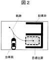
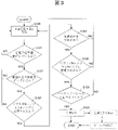
- FIG. FIG. 4 is a conceptual diagram for explaining backward parking including a vehicle turning operation, which is detected as vehicle behavior by a vehicle behavior determination unit 103 in the map storage system of the first embodiment. 4 is a flowchart for explaining a map information storage operation in the first embodiment
- FIG. 10 is a conceptual diagram for explaining forward parking detected as vehicle behavior by a vehicle behavior determination unit 103 in the map storage system of the second embodiment
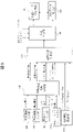
- FIG. 2 is a block diagram schematically illustrating the overall configuration of a map storage system according to a second embodiment
- FIG. FIG. 11 is a flowchart for explaining a map information storage operation in the second embodiment
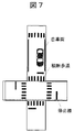
- FIG. 11 is a conceptual diagram illustrating entry into an intersection detected as behavior of a vehicle by a vehicle behavior determination unit 103 in the map storage system of the third embodiment
- FIG. 12 is a block diagram schematically illustrating the overall configuration of a map storage system according to a fourth embodiment
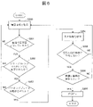
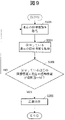
- FIG. 16 is a flowchart for explaining a map information storage operation in the fourth embodiment
- the overall configuration of the map storage system of the first embodiment will be schematically described with reference to the functional block diagram of FIG.
- This map storage system is mounted on a vehicle and includes a map generation section 100 , a map data temporary storage section 101 and a map data storage section 102 .
- the map generation unit 100 is configured to be able to communicate with the map data temporary storage unit 101 and the map data storage unit 102 wirelessly or by wire.
- the map generation unit 100 temporarily stores the generated map in the map data temporary storage unit 101, and under predetermined conditions, non-temporarily stores the map temporarily stored in the map data temporary storage unit 101 (delete command). It has a function of storing in the map data storage unit 102 for a long term or permanently unless there is such a condition.
- the map data temporary storage unit 101 is auxiliary storage means configured to temporarily store various data, and is composed of a semiconductor memory.
- the map data temporary storage unit 101 temporarily stores a predetermined amount of map data only for a predetermined period or under certain conditions, and discards the data when it is determined that non-temporary storage is unnecessary.
- the semiconductor memory that constitutes the map data temporary storage unit 101 may be a volatile memory such as a DRAM, or a non-volatile memory such as a flash memory, MRAM, or ReRAM.
- the map data storage unit 102 is storage means that can store various data non-temporarily, and is preferably a storage that can read and write large amounts of data and can store data in a non-volatile manner.
- map data storage unit 102 does not necessarily have to be mounted on the vehicle, and may be mounted on a server or the like that can communicate with the vehicle.
- the map generation unit 100 has a function of generating a map from three-dimensional position information and feature points obtained from a ranging sensor (not shown) such as LiDAR (Light Detection and Ranging) or SONAR.
- the map generating unit 100 also has a function of detecting three-dimensional objects such as signs and traffic lights, figures (paint) on road surfaces such as lanes and pedestrian crossings, etc. from images captured by an on-board camera (not shown), and generating a map.
- the map generating unit 100 can generate a map by measuring an image obtained by running a vehicle.
- the map generation unit 100 has a function of constantly generating a map after the system is started, and cyclically storing the map data in the map data temporary storage unit 101 as a ring buffer.
- the capacity of the data stored in the map data temporary storage unit 101 can be determined according to conditions such as the size of the temporary storage data, the distance traveled by the vehicle, and the travel time.
- the map generation unit 100 is configured to start storing map data in the map data storage unit 102 when a predetermined behavior of the vehicle in which it is mounted is detected. Therefore, this map storage system includes a vehicle behavior determination section 103, a vehicle speed input section 104, a vehicle steering input section 105, a vehicle shift input section 106, and a vehicle parking brake input section 107 as components for determining vehicle behavior. , a behavior history information storage unit 108 , and a vehicle behavior determination unit 103 .
- the term "behavior" of the vehicle is used in a broader sense, including not only the case where the main body of the vehicle is moving, but also the case where only some of the components of the vehicle are moving. solved. The "behavior” here also includes the case where the vehicle itself does not move and is stopped.
- the vehicle behavior determination unit 103 determines rearward parking including a turning operation of the vehicle as shown in FIG.
- the map generation unit 100 is instructed to store the map stored in the map data storage unit 102 non-temporarily.
- the vehicle speed input unit 104 has a function of inputting information about the speed of the vehicle (vehicle speed information) obtained from a speedometer (not shown) mounted on the vehicle. Further, the vehicle steering input unit 105 inputs information (steering information) regarding the steering amount of the steering wheel of the vehicle from a power steering system or the like (not shown). A vehicle shift input unit 106 inputs shift information regarding a gear shift of the vehicle from an automatic transmission of an automatic transmission system. The vehicle parking brake input unit 107 inputs parking brake information regarding control of the parking brake of the vehicle.
- the behavior history information storage unit 108 receives various types of information regarding vehicle behavior from the various input units 104 to 107 described above over a certain period of time, and stores the information as behavior history information.
- the vehicle behavior determination unit 103 determines vehicle behavior based on various information stored in the behavior history information storage unit 108 .
- the various behavior history information input from the various input units 104 to 107 described above are examples of information for determining the behavior of the vehicle, and are not limited to the combinations shown in FIG. .
- Input units other than those shown in FIG. 1 may be additionally employed, and various input units shown in FIG. 1 may be replaced with other input units.
- an input unit for inputting information regarding brake operation may be additionally employed, or an input unit for inputting sensing information of a sensor for detecting opening/closing of a door may be employed.
- control signals and driving assistance information from the automatic driving function and the driving assistance function may be input.
- the behavior history information storage unit 108 starts storing behavior history information when the vehicle speed from the vehicle speed input unit 104 becomes equal to or less than a threshold.
- the threshold here can be, for example, 20 km/h.
- various information from other input units 105 to 107 are started to be stored in behavior history information storage unit 108 when predetermined conditions are satisfied.
- Multiple types of behavior history information can be collectively stored in the behavior history information storage unit 108 when conditions for multiple types of behavior information are satisfied.
- the behavior information may be stored in the behavior history information storage unit 108 when the conditions for each of a plurality of types of behavior information are satisfied.
- the vehicle behavior determination unit 103 determines the behavior of the vehicle from the behavior information stored in the behavior history information storage unit 108 in this manner.
- the operation in the vehicle behavior determination unit 103 is shown when the vehicle approaches the parking lot at low speed, switches to the reverse gear, starts to reverse, and determines whether or not the vehicle is parked backwards.
- the map generation unit 100 generates map data based on information from the vehicle-mounted camera, LiDAR, SONAR, etc., and stores the generated map data in the map data temporary storage unit 101.
- a predetermined threshold value for example, 20 km/h
- the behavior history information storage unit 108 receives various behavior history information (vehicle speed information, steering information, shift information, Parking brake information) is input, and storage (acquisition) thereof is started (step S100).
- steps S101 to S106 it is determined whether or not the behavior history information input from the various input units 104 to 107 satisfies predetermined conditions. If a negative (No) determination is made in any of steps S101 to S106, the process returns to step S100 and the same operation is repeated.
- step S101 the vehicle behavior determination unit 103 determines whether or not the vehicle is moving forward at a low speed (for example, 10 km/h or less) based on vehicle speed information. If an affirmative determination (Yes) is made in step S101, the process proceeds to step S102.
- a low speed for example, 10 km/h or less
- step S102 the vehicle behavior determination unit 103 determines whether or not the steering wheel of the vehicle is being steered by a threshold value or more based on the operation information.
- the threshold here is set to a value that determines whether or not the vehicle has been steered by a certain amount or more, which is not performed in normal driving, in order to cause the vehicle to approach the target position backwards. If an affirmative determination (Yes) is made in step S102, the process proceeds to step S103.
- step S103 the vehicle behavior determination unit 103 determines whether the shift lever is changed from the "D" range (forward) to the "R" range (reverse) in order to move the vehicle backward based on the shift information. It is determined whether a cutback has occurred. If an affirmative determination (Yes) is made in step S103, the process proceeds to step S104.
- step S104 the vehicle behavior determination unit 103 determines whether or not the vehicle is traveling backwards to park at the target parking position based on the shift information and vehicle speed information (step S104). If an affirmative determination (Yes) is made in step S104, the process proceeds to step S105.
- step S105 the vehicle behavior determination unit 103 determines whether or not the shift lever has been changed from the "R" range to the "P" range (parking) after the vehicle reaches the target position based on the shift information. If an affirmative determination (Yes) is made in step S105, the process proceeds to step S106.
- step S106 the vehicle behavior determination unit 103 determines whether or not the parking brake has been operated in the vehicle based on the parking brake information (step S106).
- the vehicle behavior determination unit 103 determines that the vehicle has completed parking at the target parking position, and sends the map generation unit 100 , to transfer the map stored in the map data temporary storage unit 101 to the map data storage unit 102 for storage (step S107).
- the display unit of the navigation system of the vehicle may display that the map data around the parking lot has been stored. This allows the user (driver) to know that the map data has been stored.
- a data deletion button may be displayed on the display unit so that the user can instruct to delete the data when the user considers that the map storage is unnecessary. As a result, wasteful consumption of the capacity of the map data storage unit 102 is suppressed.
- the vehicle cannot be parked at the target position due to proximity or contact with surrounding objects.
- the range may be switched to the "R” range again to resume the backward movement of the vehicle.
- the shift lever may be returned to "R" or "D” to restart the parking operation.
- steps S101 to 106 in FIG. 3 are executed in that order. It is also preferable to determine whether or not.
- the movement trajectory may be calculated from the speed information and the steering information of the own vehicle, and the completion of the parking operation may be determined from the movement trajectory.
- the vehicle behavior determination unit 103 determines that the vehicle has behaved in a predetermined manner.
- the map data stored in the map data temporary storage unit 101 can be non-temporarily stored in the map data storage unit 102 . Therefore, it is possible to appropriately store a necessary map without relying on user operation or navigation information.
- FIG. 1 a map storage system according to a second embodiment will be described with reference to FIGS. 4 to 6.
- the map storage system of the second embodiment as in the first embodiment, when the vehicle behavior determination unit 103 determines that a predetermined vehicle behavior has occurred, the map storage system It instructs the map generating section 100 to store the map temporarily stored in the data temporary storage section 101 in the map data storage section 102 non-temporarily.
- the second embodiment it is determined whether or not the vehicle is parked forward, and the map information in the vicinity of the parking position of the forward parking is stored.
- FIG. 4 schematically illustrates an example of forward parking.
- FIG. 4(a) illustrates a situation of forward parking in a parking lot with parking slots.
- FIG. 4(b) describes a situation in which the vehicle is parked facing forward in the home parking lot.
- the map storage system of the second embodiment further includes an external world information acquisition unit 109 that acquires external world information. , and the behavior history information, the vehicle behavior determination unit 103 determines the behavior of the vehicle.
- the external world information acquisition unit 109 is configured to acquire space information in the traveling direction of the vehicle, and to acquire information regarding the presence or absence of vehicles around the own vehicle.
- an external world information acquisition unit 109 is added to the configuration of the first embodiment, and determination is made according to the procedure described in FIG. Also in , it is possible to determine that the destination has been reached. Then, the map information around the forward parking position can be obtained and stored without instructions from the user.
- the map generation unit 100 generates map data while the vehicle is running based on information from an in-vehicle camera, LiDAR, SONAR, etc., and temporarily stores the generated map data. Stored in the storage unit 101 .
- the behavior history information storage unit 108 receives various behavior history information (vehicle speed information, steering information, shift information, Parking brake information) is input, and storage (acquisition) thereof is started (step S200).
- steps S201 to S206 it is determined whether or not the behavior history information input from the various input units 104 to 107 satisfies a predetermined condition. It is determined whether or not the situation around the vehicle has reached a predetermined situation. If a negative (No) determination is made in any of steps S201 to S206, the process returns to step S200 and the same operations are repeated.
- step S201 the vehicle behavior determination unit 103 determines whether or not the vehicle is moving forward at a low speed (for example, 10 km/h or less) based on vehicle speed information. If an affirmative determination (Yes) is made in step S201, the process proceeds to step S202.
- the external world information acquisition unit 109 may detect a parking frame and determine whether the host vehicle is moving to this parking frame.
- step S202 the vehicle behavior determination unit 103 determines based on the shift information whether the shift lever has been changed from the "D" range to the "P" range in order to park the vehicle in the parking position. If an affirmative determination (Yes) is made in step S202, the process proceeds to step S203.
- step S203 the vehicle behavior determination unit 103 determines whether or not the parking brake has been operated after the vehicle reaches the parking position based on the parking brake information. If an affirmative determination (Yes) is made in step S203, the process proceeds to step S204.
- step S204 the external world information is acquired by the external world information acquisition unit 109. Then, in the subsequent step S205, it is determined whether or not there is a wall in the space ahead of the vehicle and there is no other object, based on the external world information (step S205). If the determination in step S205 is affirmative (Yes), the process proceeds to step S206.
- step S206 based on the external world information acquired by the external world information acquisition unit 109, it is determined whether or not there is another vehicle around the own vehicle. If affirmative determination (Yes) is made in step S206, the process proceeds to step S207. In step S206, it may be determined that the vehicle is in the space surrounded by the walls of the parking lot by detecting the surrounding walls of the vehicle based on the external world information. If the determination in step S206 is affirmative (Yes), the vehicle behavior determination unit 103 determines that the vehicle has completed parking at the target parking position. to transfer the map stored in the map data storage unit 102 and store it in the map data storage unit 102 (step S107).
- the vehicle behavior determining unit 103 determines that a predetermined vehicle behavior (forward parking) has occurred. Based on the determination result, the map generation unit 100 can cause the map data stored in the map data temporary storage unit 101 to be non-temporarily stored in the map data storage unit 102 . Therefore, it is possible to appropriately store a necessary map without relying on user operation or navigation information.
- the map storage system of the third embodiment determines that a predetermined vehicle behavior has occurred, the map data It instructs the map generating section 100 to store the map temporarily stored in the temporary storage section 101 in the map data storage section 102 non-temporarily.
- the map storage system of the third embodiment determines that a vehicle enters an intersection as the behavior of the vehicle, and stores the map information in the vicinity of the intersection from the map data temporary storage unit 101 to the map data storage unit 102. It is configured to be transferred to and stored non-temporarily.
- the overall configuration of the map storage system of the third embodiment is similar to that of the second embodiment (FIG. 5), with the external world information acquisition unit 109 added to the system of the first embodiment. can be done.
- the external world information acquisition unit 109 when it is detected that the vehicle speed is equal to or less than a predetermined threshold value and the steering amount of the steering wheel of the vehicle is equal to or greater than a predetermined value, the external world information acquisition unit 109 , pedestrian crossings, stop lines, traffic lights, etc. are acquired as external information.
- the vehicle behavior judgment unit 103 judges that the vehicle has entered the intersection, and the map data captured and stored around the intersection is transferred from the map data temporary storage unit 101 to the map data storage unit 102. can be memorized.
- the vehicle behavior determination unit 103 determines that there is a predetermined vehicle behavior (entering an intersection).
- the map generation unit 100 can cause the map data stored in the map data temporary storage unit 101 to be non-temporarily stored in the map data storage unit 102 . Therefore, it is possible to appropriately store a necessary map without relying on user operation or navigation information.
- FIG. 8 a map storage system according to a fourth embodiment will be described with reference to FIGS. 8 and 9.
- the map storage system of the fourth embodiment as in the above-described embodiments, when the vehicle behavior determination unit 103 determines that a predetermined vehicle behavior has occurred, the map data It instructs the map generating section 100 to store the map temporarily stored in the temporary storage section 101 in the map data storage section 102 non-temporarily.
- the behavior history information storage unit 108 includes an earth coordinate input unit 110 for acquiring coordinate information from a position detection device on the earth such as GPS. is connected.
- GPS data coordinate information
- behavior history information is provided as behavior history information from the earth coordinate input unit 110, which is different from the above-described embodiment. For example, the GPS data of roads that the vehicle frequently travels on are acquired, the behavior of the vehicle is determined according to the GPS data, and it is determined whether or not to store the map.
- the behavior history information storage unit 108 appropriately stores the coordinate information input from the earth coordinate input unit 110 including past information, and the vehicle behavior determination unit 103 determines whether the past coordinate information and the current coordinate information are the same. Then, according to the determination result, the map generation unit 100 is instructed to non-temporarily store the data stored in the map data temporary storage unit 101 in the map data storage unit 102 . As an example, the vehicle behavior determination unit 103 determines that the past coordinate information and the current coordinate information are the same when the same coordinate information is obtained over a range equal to or greater than a predetermined number of times (for example, 3 times). can be determined.
- a predetermined number of times for example, 3 times
- the map generation unit 100 generates map data while the vehicle is running based on information from an in-vehicle camera, LiDAR, SONAR, etc., and temporarily stores the generated map data. Stored in unit 101 . During this time, the behavior history information storage unit 108 appropriately acquires the current coordinate information of the vehicle from the earth coordinate input unit 110 (step S300).
- the vehicle behavior determination unit 103 acquires past coordinate information stored in the behavior history information storage unit 108 (step S301), and It is determined whether the degree of matching between the information and the current coordinate information is equal to or greater than a predetermined threshold, and whether matching has been confirmed multiple times at the same position in the past (step S302). If this determination is affirmative (Yes), it is determined that the position is a position (such as a road) that is frequently passed through. to transfer the map stored in the map data storage unit 102 and store it in the map data storage unit 102 (step S303).
- the vehicle behavior determination unit 103 determines that the vehicle has behaved in a predetermined manner (that the vehicle has passed through a road that is frequently traveled).
- the map generation unit 100 can cause the map data stored in the map data temporary storage unit 101 to be non-temporarily stored in the map data storage unit 102 . Therefore, it is possible to appropriately store a necessary map without relying on user operation or navigation information.
- the present disclosure is not limited to the above-described embodiments, and includes various modifications.
- the above-described embodiments have been described in detail in order to explain the present disclosure in an easy-to-understand manner, and do not necessarily include all the configurations described.
- part of an embodiment can be replaced with the configuration of another embodiment.
- the configuration of one embodiment can be added to the configuration of another embodiment.
- a part of the configuration of each embodiment can be added, deleted or replaced with a part of the configuration of another embodiment.
Landscapes
- Engineering & Computer Science (AREA)
- Radar, Positioning & Navigation (AREA)
- Remote Sensing (AREA)
- Physics & Mathematics (AREA)
- General Physics & Mathematics (AREA)
- Automation & Control Theory (AREA)
- Theoretical Computer Science (AREA)
- Mathematical Physics (AREA)
- Databases & Information Systems (AREA)
- Business, Economics & Management (AREA)
- Educational Administration (AREA)
- Educational Technology (AREA)
- Transportation (AREA)
- Mechanical Engineering (AREA)
- Traffic Control Systems (AREA)
- Instructional Devices (AREA)
- Navigation (AREA)
- Control Of Driving Devices And Active Controlling Of Vehicle (AREA)
Abstract
Description
図1の機能ブロック図を参照して、第1の実施の形態の地図記憶システムの全体構成を概略的に説明する。この地図記憶システムは、車両に搭載され、地図生成部100と、地図データ一時記憶部101と、地図データ記憶部102とを備える。地図生成部100は、地図データ一時記憶部101及び地図データ記憶部102と、無線又は有線により通信可能に構成される。地図生成部100は、生成した地図を地図データ一時記憶部101に一時的に記憶させると共に、所定の条件の下、地図データ一時記憶部101に一時記憶した地図を、非一時的に(消去命令等が無い限り、長期的又は永続的に)地図データ記憶部102に記憶させる機能を有する。
次に、図4~図6を参照して、第2の実施の形態の地図記憶システムを説明する。この第2の実施の形態の地図記憶システムも、第1の実施の形態と同様に、車両挙動判定部103において、所定の車両の挙動があったと車両挙動判定部103が判定した場合に、地図データ一時記憶部101に一時的に記憶されている地図を地図データ記憶部102に非一時的に記憶させることを地図生成部100に指示するものである。ただし、この第2の実施の形態は、車両の前向き駐車がされたか否かを判定して、その前向き駐車の駐車位置付近での地図情報を記憶するよう構成されているものである。
ステップS206で肯定的な判定(Yes)がなされると、車両挙動判定部103は、車両は目的の駐車位置に駐車を完了したと判定し、地図生成部100に対し、地図データ一時記憶部101に記憶している地図を地図データ記憶部102に転送し記憶させることを指示する(ステップS107)。
次に、図7を参照して、第3の実施の形態の地図記憶システムを説明する。この第3の実施の形態の地図記憶システムも、前述の実施の形態と同様に、車両挙動判定部103において、所定の車両の挙動があったと車両挙動判定部103が判定した場合に、地図データ一時記憶部101に一時的に記憶されている地図を地図データ記憶部102に非一時的に記憶させることを地図生成部100に指示するものである。ただし、この第3の実施の形態の地図記憶システムは、車両の交差点への進入を車両の挙動として判定して、その交差点付近での地図情報を地図データ一時記憶部101から地図データ記憶部102に転送し非一時的に記憶するよう構成されているものである。
次に、図8~図9を参照して、第4の実施の形態の地図記憶システムを説明する。この第4の実施の形態の地図記憶システムも、前述の実施の形態と同様に、車両挙動判定部103において、所定の車両の挙動があったと車両挙動判定部103が判定した場合に、地図データ一時記憶部101に一時的に記憶されている地図を地図データ記憶部102に非一時的に記憶させることを地図生成部100に指示するものである。
101…地図データ一時記憶部
102…地図データ記憶部
103…車両挙動判定部
104…車両速度入力部
105…車両操舵入力部
106…車両シフト入力部
107…車両パーキングブレーキ入力部
108…挙動履歴情報保存部
109…外界情報取得部
110…地球座標入力部
Claims (9)
- 車両が走行した経路の地図データを作成する地図作成部と、
前記地図データを一時的に記憶する地図データ一時記憶部と、
前記地図データ一時記憶部に一時的に記憶された前記地図データの一部を非一時的に記憶する地図データ記憶部と、
前記車両の挙動の履歴である挙動履歴情報を保存する挙動履歴情報保存部と、
前記地図データ一時記憶部に一時的に記憶された前記地図データを前記地図データ記憶部に記憶するか否かを、前記挙動履歴情報に基づいて判定する車両挙動判定部と
を備えることを特徴とする地図記憶装置。 - 前記車両の車速が閾値以下となった場合、前記挙動履歴情報保存部は、前記挙動履歴情報の保存を開始することを特徴とする請求項1に記載の地図記憶装置。
- 前記車両挙動判定部は、前記車両のシフトレバーの操作に基づいて、前記車両が所定の動作を行っているか否かを判定するように構成される、請求項1に記載の地図記憶装置。
- 前記車両挙動判定部は、前記車両の速度、及びハンドルの操舵量に基づいて、前記車両が所定の動作を行っているか否かを判定するように構成される、請求項3に記載の地図記憶装置。
- 前記車両挙動判定部は、前記車両のパーキングブレーキの操作情報に基づき、前記車両が所定の動作を行っているか否かを判定するように構成される、請求項4に記載の地図記憶装置。
- 前記車両の周囲の情報である外界情報を取得する外界情報取得部を更に備え、
前記車両挙動判定部は、前記外界情報、及び前記挙動履歴情報に基づいて、前記地図データ一時記憶部に一時的に記憶された前記地図データを前記地図データ記憶部に記憶するか否かを判定する、請求項1に記載の地図記憶装置。 - 前記外界情報取得部は、前記車両の停止時における前記車両の周囲の情報を取得するよう構成される、請求項6に記載の地図記憶装置。
- 前記外界情報取得部は、前記車両が走行する路面の走行車線、及び路面表示に関する情報を取得するよう構成される、請求項6に記載の地図記憶装置。
- 前記車両の地球上の座標情報を取得する地球座標入力部を備え、前記挙動履歴情報保存部は、前記座標情報を保存するように構成される、請求項1に記載の地図記憶装置。
Priority Applications (3)
| Application Number | Priority Date | Filing Date | Title |
|---|---|---|---|
| US18/261,911 US20240085213A1 (en) | 2021-03-25 | 2021-09-22 | Map storage device |
| JP2023508438A JP7518283B2 (ja) | 2021-03-25 | 2021-09-22 | 地図記憶装置 |
| JP2024107990A JP7759442B2 (ja) | 2021-03-25 | 2024-07-04 | 地図記憶装置 |
Applications Claiming Priority (2)
| Application Number | Priority Date | Filing Date | Title |
|---|---|---|---|
| JP2021050948 | 2021-03-25 | ||
| JP2021-050948 | 2021-03-25 |
Publications (1)
| Publication Number | Publication Date |
|---|---|
| WO2022201595A1 true WO2022201595A1 (ja) | 2022-09-29 |
Family
ID=83395508
Family Applications (1)
| Application Number | Title | Priority Date | Filing Date |
|---|---|---|---|
| PCT/JP2021/034771 Ceased WO2022201595A1 (ja) | 2021-03-25 | 2021-09-22 | 地図記憶装置 |
Country Status (3)
| Country | Link |
|---|---|
| US (1) | US20240085213A1 (ja) |
| JP (2) | JP7518283B2 (ja) |
| WO (1) | WO2022201595A1 (ja) |
Families Citing this family (1)
| Publication number | Priority date | Publication date | Assignee | Title |
|---|---|---|---|---|
| DE102024132365A1 (de) * | 2024-11-06 | 2026-05-07 | Audi Aktiengesellschaft | Verfahren zum Betreiben einer Fahrerassistenzeinrichtung für ein Kraftfahrzeug, Fahrerassistenzeinrichtung für ein Kraftfahrzeug sowie Computerprogrammprodukt |
Citations (8)
| Publication number | Priority date | Publication date | Assignee | Title |
|---|---|---|---|---|
| JP2001264074A (ja) * | 2000-03-14 | 2001-09-26 | Alpine Electronics Inc | 車載用電子機器 |
| JP2005156169A (ja) * | 2003-11-20 | 2005-06-16 | Nissan Motor Co Ltd | タイミング制御型ダウンロードシステム |
| JP2012162232A (ja) * | 2011-02-09 | 2012-08-30 | Toyota Motor Corp | 車両用情報処理装置 |
| JP2013076574A (ja) * | 2011-09-29 | 2013-04-25 | Clarion Co Ltd | 情報端末 |
| US20180189323A1 (en) * | 2016-12-30 | 2018-07-05 | DeepMap Inc. | High definition map and route storage management system for autonomous vehicles |
| JP2018205093A (ja) * | 2017-06-02 | 2018-12-27 | 本田技研工業株式会社 | 自動走行制御システム |
| JP2019164840A (ja) * | 2019-06-24 | 2019-09-26 | 株式会社デンソー | 情報処理装置及び情報処理システム |
| WO2019220206A1 (ja) * | 2018-05-15 | 2019-11-21 | 日産自動車株式会社 | 乗車位置算出方法、乗車位置算出装置、ならびに、乗車位置算出システム |
Family Cites Families (9)
| Publication number | Priority date | Publication date | Assignee | Title |
|---|---|---|---|---|
| JP2004125544A (ja) * | 2002-10-01 | 2004-04-22 | Seiko Epson Corp | ナビゲーション装置、電子機器及びプログラム |
| JP6524892B2 (ja) | 2015-11-13 | 2019-06-05 | 株式会社デンソー | 車両の走行路情報生成システム |
| US10528059B2 (en) * | 2017-05-24 | 2020-01-07 | Uatc, Llc | Systems and methods for controlling autonomous vehicles that provide a vehicle service to users |
| JP7079620B2 (ja) * | 2018-02-23 | 2022-06-02 | フォルシアクラリオン・エレクトロニクス株式会社 | 履歴情報記憶装置、経路の算出方法、影響範囲配信システム |
| US10846955B2 (en) * | 2018-03-16 | 2020-11-24 | Micron Technology, Inc. | Black box data recorder for autonomous driving vehicle |
| JP7088613B2 (ja) | 2019-02-26 | 2022-06-21 | アルパイン株式会社 | 電子装置およびシステム |
| US11988518B2 (en) * | 2019-06-17 | 2024-05-21 | Nvidia Corporation | Updating high definition maps based on lane closure and lane opening |
| US20210201666A1 (en) * | 2019-12-31 | 2021-07-01 | Oath Inc. | Scalable and distributed detection of road anomaly events |
| CN115917616B (zh) * | 2020-06-23 | 2025-03-25 | 株式会社电装 | 障碍物信息管理装置、障碍物信息管理方法、车辆用装置 |
-
2021
- 2021-09-22 US US18/261,911 patent/US20240085213A1/en active Pending
- 2021-09-22 JP JP2023508438A patent/JP7518283B2/ja active Active
- 2021-09-22 WO PCT/JP2021/034771 patent/WO2022201595A1/ja not_active Ceased
-
2024
- 2024-07-04 JP JP2024107990A patent/JP7759442B2/ja active Active
Patent Citations (8)
| Publication number | Priority date | Publication date | Assignee | Title |
|---|---|---|---|---|
| JP2001264074A (ja) * | 2000-03-14 | 2001-09-26 | Alpine Electronics Inc | 車載用電子機器 |
| JP2005156169A (ja) * | 2003-11-20 | 2005-06-16 | Nissan Motor Co Ltd | タイミング制御型ダウンロードシステム |
| JP2012162232A (ja) * | 2011-02-09 | 2012-08-30 | Toyota Motor Corp | 車両用情報処理装置 |
| JP2013076574A (ja) * | 2011-09-29 | 2013-04-25 | Clarion Co Ltd | 情報端末 |
| US20180189323A1 (en) * | 2016-12-30 | 2018-07-05 | DeepMap Inc. | High definition map and route storage management system for autonomous vehicles |
| JP2018205093A (ja) * | 2017-06-02 | 2018-12-27 | 本田技研工業株式会社 | 自動走行制御システム |
| WO2019220206A1 (ja) * | 2018-05-15 | 2019-11-21 | 日産自動車株式会社 | 乗車位置算出方法、乗車位置算出装置、ならびに、乗車位置算出システム |
| JP2019164840A (ja) * | 2019-06-24 | 2019-09-26 | 株式会社デンソー | 情報処理装置及び情報処理システム |
Also Published As
| Publication number | Publication date |
|---|---|
| JP7759442B2 (ja) | 2025-10-23 |
| JP2024127985A (ja) | 2024-09-20 |
| JPWO2022201595A1 (ja) | 2022-09-29 |
| JP7518283B2 (ja) | 2024-07-17 |
| US20240085213A1 (en) | 2024-03-14 |
Similar Documents
| Publication | Publication Date | Title |
|---|---|---|
| US10852726B2 (en) | Systems and methods for transitioning a vehicle from an autonomous driving mode to a manual driving mode | |
| CN110473416B (zh) | 车辆控制装置 | |
| US10054678B2 (en) | Minimizing incorrect sensor data associations for autonomous vehicles | |
| US11216000B2 (en) | System and method for estimating lane prediction errors for lane segments | |
| CN107783535B (zh) | 车辆控制装置 | |
| US10884410B2 (en) | Systems and methods for determining whether a vehicle is capable of navigating an intersection in an autonomous driving mode | |
| US9429440B2 (en) | Driving action determination for travel route exit event | |
| JP2021049969A (ja) | ハンドルのニュートラル位置を較正するためのシステムおよび方法 | |
| CN110874229A (zh) | 自动驾驶汽车的地图升级方法、装置 | |
| US10261516B2 (en) | Vehicle control device | |
| JPWO2019003314A1 (ja) | 通知システムおよびその制御方法、車両、並びにプログラム | |
| JP2016215733A (ja) | 車両制御装置 | |
| JP7377822B2 (ja) | 運転支援方法及び運転支援装置 | |
| JP2020042007A (ja) | 地図上のランドマークを使用して車両の長手方向位置を補正するためのシステム及び方法 | |
| EP3722751B1 (en) | Systems and methods for determining a location of a vehicle within a structure | |
| JP2022041910A (ja) | 制御システム、非一時的コンピュータ可読媒体、及び方法 | |
| JP2020056733A (ja) | 車両制御装置 | |
| JP2020023214A (ja) | 運転支援方法及び運転支援装置 | |
| JP7759442B2 (ja) | 地図記憶装置 | |
| US10599146B2 (en) | Action-conditioned vehicle control | |
| JP4176616B2 (ja) | 車両の走行制御装置 | |
| CN111273653B (zh) | 自动驾驶装置 | |
| US20240182055A1 (en) | Method for Operating an Assistance System of a Vehicle With Proactive Suggestion for Carrying Out an Assistance Function, Assistance System, and Vehicle | |
| JP2018067034A (ja) | 移動体制御装置、移動体制御方法、および、移動体制御装置用プログラム | |
| WO2021246004A1 (ja) | 車両制御装置及び車両制御方法 |
Legal Events
| Date | Code | Title | Description |
|---|---|---|---|
| 121 | Ep: the epo has been informed by wipo that ep was designated in this application |
Ref document number: 21933194 Country of ref document: EP Kind code of ref document: A1 |
|
| ENP | Entry into the national phase |
Ref document number: 2023508438 Country of ref document: JP Kind code of ref document: A |
|
| WWE | Wipo information: entry into national phase |
Ref document number: 18261911 Country of ref document: US |
|
| NENP | Non-entry into the national phase |
Ref country code: DE |
|
| 122 | Ep: pct application non-entry in european phase |
Ref document number: 21933194 Country of ref document: EP Kind code of ref document: A1 |