WO2022201590A1 - 車両駆動モータ - Google Patents
車両駆動モータ Download PDFInfo
- Publication number
- WO2022201590A1 WO2022201590A1 PCT/JP2021/033454 JP2021033454W WO2022201590A1 WO 2022201590 A1 WO2022201590 A1 WO 2022201590A1 JP 2021033454 W JP2021033454 W JP 2021033454W WO 2022201590 A1 WO2022201590 A1 WO 2022201590A1
- Authority
- WO
- WIPO (PCT)
- Prior art keywords
- oil
- drive motor
- vehicle drive
- output shaft
- bearing
- Prior art date
- Legal status (The legal status is an assumption and is not a legal conclusion. Google has not performed a legal analysis and makes no representation as to the accuracy of the status listed.)
- Ceased
Links
Images



Classifications
-
- H—ELECTRICITY
- H02—GENERATION; CONVERSION OR DISTRIBUTION OF ELECTRIC POWER
- H02K—DYNAMO-ELECTRIC MACHINES
- H02K9/00—Arrangements for cooling or ventilating
- H02K9/19—Arrangements for cooling or ventilating for machines with closed casing and closed-circuit cooling using a liquid cooling medium, e.g. oil
-
- H—ELECTRICITY
- H02—GENERATION; CONVERSION OR DISTRIBUTION OF ELECTRIC POWER
- H02K—DYNAMO-ELECTRIC MACHINES
- H02K5/00—Casings; Enclosures; Supports
- H02K5/04—Casings or enclosures characterised by the shape, form or construction thereof
- H02K5/20—Casings or enclosures characterised by the shape, form or construction thereof with channels or ducts for flow of cooling medium
- H02K5/203—Casings or enclosures characterised by the shape, form or construction thereof with channels or ducts for flow of cooling medium specially adapted for liquids, e.g. cooling jackets
-
- H—ELECTRICITY
- H02—GENERATION; CONVERSION OR DISTRIBUTION OF ELECTRIC POWER
- H02K—DYNAMO-ELECTRIC MACHINES
- H02K9/00—Arrangements for cooling or ventilating
- H02K9/19—Arrangements for cooling or ventilating for machines with closed casing and closed-circuit cooling using a liquid cooling medium, e.g. oil
- H02K9/197—Arrangements for cooling or ventilating for machines with closed casing and closed-circuit cooling using a liquid cooling medium, e.g. oil in which the rotor or stator space is fluid-tight, e.g. to provide for different cooling media for rotor and stator
-
- F—MECHANICAL ENGINEERING; LIGHTING; HEATING; WEAPONS; BLASTING
- F16—ENGINEERING ELEMENTS AND UNITS; GENERAL MEASURES FOR PRODUCING AND MAINTAINING EFFECTIVE FUNCTIONING OF MACHINES OR INSTALLATIONS; THERMAL INSULATION IN GENERAL
- F16H—GEARING
- F16H57/00—General details of gearing
- F16H57/04—Features relating to lubrication or cooling or heating
- F16H57/042—Guidance of lubricant
- F16H57/0421—Guidance of lubricant on or within the casing, e.g. shields or baffles for collecting lubricant, tubes, pipes, grooves, channels or the like
- F16H57/0423—Lubricant guiding means mounted or supported on the casing, e.g. shields or baffles for collecting lubricant, tubes or pipes
-
- F—MECHANICAL ENGINEERING; LIGHTING; HEATING; WEAPONS; BLASTING
- F16—ENGINEERING ELEMENTS AND UNITS; GENERAL MEASURES FOR PRODUCING AND MAINTAINING EFFECTIVE FUNCTIONING OF MACHINES OR INSTALLATIONS; THERMAL INSULATION IN GENERAL
- F16H—GEARING
- F16H57/00—General details of gearing
- F16H57/04—Features relating to lubrication or cooling or heating
- F16H57/042—Guidance of lubricant
- F16H57/0421—Guidance of lubricant on or within the casing, e.g. shields or baffles for collecting lubricant, tubes, pipes, grooves, channels or the like
- F16H57/0424—Lubricant guiding means in the wall of or integrated with the casing, e.g. grooves, channels, holes
-
- F—MECHANICAL ENGINEERING; LIGHTING; HEATING; WEAPONS; BLASTING
- F16—ENGINEERING ELEMENTS AND UNITS; GENERAL MEASURES FOR PRODUCING AND MAINTAINING EFFECTIVE FUNCTIONING OF MACHINES OR INSTALLATIONS; THERMAL INSULATION IN GENERAL
- F16H—GEARING
- F16H57/00—General details of gearing
- F16H57/04—Features relating to lubrication or cooling or heating
- F16H57/0457—Splash lubrication
-
- F—MECHANICAL ENGINEERING; LIGHTING; HEATING; WEAPONS; BLASTING
- F16—ENGINEERING ELEMENTS AND UNITS; GENERAL MEASURES FOR PRODUCING AND MAINTAINING EFFECTIVE FUNCTIONING OF MACHINES OR INSTALLATIONS; THERMAL INSULATION IN GENERAL
- F16H—GEARING
- F16H57/00—General details of gearing
- F16H57/04—Features relating to lubrication or cooling or heating
- F16H57/0467—Elements of gearings to be lubricated, cooled or heated
- F16H57/0469—Bearings or seals
- F16H57/0471—Bearing
-
- F—MECHANICAL ENGINEERING; LIGHTING; HEATING; WEAPONS; BLASTING
- F16—ENGINEERING ELEMENTS AND UNITS; GENERAL MEASURES FOR PRODUCING AND MAINTAINING EFFECTIVE FUNCTIONING OF MACHINES OR INSTALLATIONS; THERMAL INSULATION IN GENERAL
- F16H—GEARING
- F16H57/00—General details of gearing
- F16H57/04—Features relating to lubrication or cooling or heating
- F16H57/0467—Elements of gearings to be lubricated, cooled or heated
- F16H57/0476—Electric machines and gearing, i.e. joint lubrication or cooling or heating thereof
-
- F—MECHANICAL ENGINEERING; LIGHTING; HEATING; WEAPONS; BLASTING
- F16—ENGINEERING ELEMENTS AND UNITS; GENERAL MEASURES FOR PRODUCING AND MAINTAINING EFFECTIVE FUNCTIONING OF MACHINES OR INSTALLATIONS; THERMAL INSULATION IN GENERAL
- F16H—GEARING
- F16H57/00—General details of gearing
- F16H57/04—Features relating to lubrication or cooling or heating
- F16H57/048—Type of gearings to be lubricated, cooled or heated
- F16H57/0493—Gearings with spur or bevel gears
- F16H57/0495—Gearings with spur or bevel gears with fixed gear ratio
-
- H—ELECTRICITY
- H02—GENERATION; CONVERSION OR DISTRIBUTION OF ELECTRIC POWER
- H02K—DYNAMO-ELECTRIC MACHINES
- H02K5/00—Casings; Enclosures; Supports
- H02K5/04—Casings or enclosures characterised by the shape, form or construction thereof
- H02K5/16—Means for supporting bearings, e.g. insulating supports or means for fitting bearings in the bearing-shields
- H02K5/173—Means for supporting bearings, e.g. insulating supports or means for fitting bearings in the bearing-shields using bearings with rolling contact, e.g. ball bearings
- H02K5/1732—Means for supporting bearings, e.g. insulating supports or means for fitting bearings in the bearing-shields using bearings with rolling contact, e.g. ball bearings radially supporting the rotary shaft at both ends of the rotor
-
- H—ELECTRICITY
- H02—GENERATION; CONVERSION OR DISTRIBUTION OF ELECTRIC POWER
- H02K—DYNAMO-ELECTRIC MACHINES
- H02K7/00—Arrangements for handling mechanical energy structurally associated with dynamo-electric machines, e.g. structural association with mechanical driving motors or auxiliary dynamo-electric machines
- H02K7/10—Structural association with clutches, brakes, gears, pulleys or mechanical starters
- H02K7/116—Structural association with clutches, brakes, gears, pulleys or mechanical starters with gears
-
- Y—GENERAL TAGGING OF NEW TECHNOLOGICAL DEVELOPMENTS; GENERAL TAGGING OF CROSS-SECTIONAL TECHNOLOGIES SPANNING OVER SEVERAL SECTIONS OF THE IPC; TECHNICAL SUBJECTS COVERED BY FORMER USPC CROSS-REFERENCE ART COLLECTIONS [XRACs] AND DIGESTS
- Y02—TECHNOLOGIES OR APPLICATIONS FOR MITIGATION OR ADAPTATION AGAINST CLIMATE CHANGE
- Y02T—CLIMATE CHANGE MITIGATION TECHNOLOGIES RELATED TO TRANSPORTATION
- Y02T10/00—Road transport of goods or passengers
- Y02T10/60—Other road transportation technologies with climate change mitigation effect
- Y02T10/64—Electric machine technologies in electromobility
Definitions
- the present invention relates to a vehicle drive motor that generates driving force for an electric vehicle, and more particularly to a vehicle drive motor that lubricates the bearings while cooling the stator coils, bearings, etc. with low-temperature oil.
- stator coils and bearings become hot when the motor rotates at high speed, so they need to be cooled. Further, in vehicle drive motors, since the life-time rotation speed of the bearings increases, there is also a demand to eliminate failures caused by running out of oil in the bearings.
- the coil with the highest temperature among the three-phase coils 20 Since oil is supplied to the ends 20a and 20b, the three-phase coil 20 is efficiently cooled.” can be used to lubricate the bearing 43 provided axially outward of the motor M, and a new lubrication structure for lubricating the bearing 43 can be eliminated. specifically explained.
- the three-phase coil (stator coil) can be cooled and the bearings lubricated while the rotary electric machine (motor) is being driven. Oil in the vicinity of the bearing may flow down, resulting in insufficient lubrication of the bearing, which may cause failure.
- the vehicle drive motor of the present invention includes a casing having a cylindrical stator coil fixed to the inner peripheral surface and an oil passage provided in the upper portion; an output shaft to which a rotor is fixed at an opposing position; a bearing that supports the output shaft; and an oil holding portion that is arranged to face the bearing and stores oil supplied from the oil passage, wherein the oil holding portion is a pocket-shaped receptacle having an upper side lower than the lower end of the output shaft and a lower side along the lower outer circumference of the bearing when viewed from the front in the axial direction of the output shaft.
- lubrication of the bearings can be maintained even when the electric vehicle has not been driven for a long period of time.
- FIG. 2 is a front view of the periphery of the oil retaining portion of Embodiment 1; First Modified Example of Oil Retaining Portion of Embodiment 1 Second Modified Example of Oil Retaining Portion of Embodiment 1 Axial sectional view of the vehicle drive motor of Embodiment 2
- FIG. 8 is a sectional view for explaining the assembly procedure of the vehicle drive motor of FIG. 7; First example of applying the oil holding part of the present invention to a speed reducer A second example in which the oil retaining portion of the present invention is applied to a speed reducer
- FIG. 10 of the comparative example is a simplified representation of a configuration related to the present invention extracted from the configuration of the electric motor of Patent Document 1.
- FIG. 10 of the comparative example is a simplified representation of a configuration related to the present invention extracted from the configuration of the electric motor of Patent Document 1.
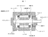
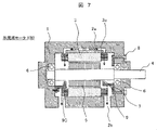
- FIG. 1 is an axial cross-sectional view of a vehicle drive motor 10 of a comparative example.
- This vehicle drive motor 10 is incorporated in an electric vehicle so that the rotation axis is horizontal, and the downward direction of the paper corresponds to the direction of gravity after installation.
- the vehicle drive motor 10 of the comparative example includes a casing 1 forming an outer shell, oil passages 2 (upper oil passage 2a, lower oil passage 2b) provided above and below the casing 1, A cylindrical stator coil 3 fixed to the inner peripheral surface of the cylindrical portion of the casing 1 , a horizontally arranged output shaft 4 , a rotor 5 fixed on the outer circumference of the output shaft 4 and at a position facing the stator coil 3 , and the output shaft 4 .
- a pair of bearings 6 (for example, roller bearings or ball bearings) that support the two at two locations, a retainer 7 that restricts the axial movement of one bearing 6, and a bolt that secures the retainer 7 to the end of the inner surface of the casing 1 8.
- the dashed arrows in the figure indicate the direction in which low-temperature oil supplied from the outside flows. After cooling the stator coil 3 connected to the casing 1, it flows downward, is stirred by the output shaft 4 that rotates at high speed, jumps up, lubricates the bearing 6, and then flows through the lower oil passage 2b that penetrates the lower part of the casing 1. It shows how the fuel is discharged to the outside of the vehicle drive motor 10 . It should be noted that the oil supplied to the upper oil passage 2a may be drawn up by the speed reducer 20 described in the third embodiment, or may be sucked up by a pump.
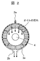
- FIG. 2 is a view of the oil flow in FIG. 1 viewed from another direction, and is a radial cross-sectional view of the vehicle drive motor 10 at a position including the right end 3a in FIG.
- illustration of the outer peripheral surface of the casing 1 is omitted here.
- oil discharged from the discharge hole of the upper oil passage 2a is divided into oil that flows along the inner peripheral surface of the casing 1 and oil that falls from the upper end portion 3a.
- the former oil sequentially cools the ends 3 a of the stator coils 3 arranged along the inner peripheral surface of the casing 1 .
- the rotation of the output shaft 4 is used to supply oil to the bearings 6. Therefore, if the electric vehicle is not operated for a long period of time, the oil near the bearings 6 will be It may flow down, and the drag loss of the bearing 6 may increase due to insufficient lubrication of the bearing 6 during the next operation, which may cause the vehicle drive motor 10 to malfunction.
- this problem becomes more important immediately after the vehicle drive motor 10 is started, because the rotational speed of the gears of the speed reducer is low and the amount of hoisting oil is small.
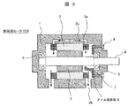
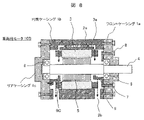
- FIG. 3 is an axial cross-sectional view of the vehicle drive motor 10A of the first embodiment.
- This vehicle drive motor 10A has the configuration of the vehicle drive motor 10 of the comparative example, and further includes an oil holding portion 9 facing the bearing 6 on the output end side.
- This oil holding portion 9 is a receiving plate member in which a part of the lower half of the retainer 7 is extended to below the end portion 3a of the stator coil 3. After hanging from the upper end portion 3a, the output shaft 4 rotates at high speed. It is for storing the relatively low-temperature oil that has been agitated and spattered by the oil and supplying it to the bearing 6.
- the prevention retainer 7 and the oil retaining portion 9 are integrally constructed, but they may be constructed separately.
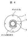
- FIG. 4 is a front view of the periphery of the oil holding portion 9 of this embodiment.
- the oil holding portion 9 is a pocket-shaped receiving plate member whose upper side is lower than the lower end of the output shaft 4 and whose lower side is along the lower outer periphery of the bearing 6 when viewed from the front in the axial direction.
- lubrication of the motor bearings can be maintained even when the electric vehicle has not been driven for a long period of time.
- the oil holding portion 9A of FIG. Equal, approximately U-shaped shapes were adopted. As a result, more oil can be stored than the oil holding portion 9 shown in FIG. 4 while the vehicle drive motor 1A is being driven. It is possible to secure a sufficient amount of remaining oil. Further, even if the electric vehicle is parked on a slope and the oil retaining portion 9A assumes the posture shown in the right diagram of FIG. A sufficient oil level required at 6 can be maintained.
- the oil holding portion 9B in FIG. 6 adopts a substantially crescent shape that surrounds the outer periphery of the output shaft 4 when viewed from the front in the axial direction, and that the height of the upper end is substantially equal to the height of the center of the output shaft 4. did.
- the vehicle drive motor 10A is being driven, excessive oil is discharged from the lower portion of the upper side of the oil holding portion 9B. Resistance can be suppressed.
- the upper end of the oil holding portion 9B is approximately the same height as the upper end of the oil holding portion 9A in FIG. Thus, a sufficient remaining amount of oil can be maintained in the oil retaining portion 9B.
- the vehicle drive motor 1A of Embodiment 1 did not establish a department.
- the vehicle drive motor 10B of this embodiment as shown in the cross-sectional view of FIG. made it Any of the oil holding portion 9 shown in FIG. 4, the oil holding portion 9A shown in FIG. 5, and the oil holding portion 9B shown in FIG. 6 may be adopted as the front view shape of the oil holding portion 9C shown in FIG.
- the retainer 7 for suppressing axial movement is provided for the right bearing 6 as in the first embodiment. Since the movement of the shaft 4 in the axial direction is suppressed, there is no need to stack and fix it with another retainer. For this reason, the portion corresponding to the retainer is omitted from the left oil holding portion 9C in consideration of the assembly procedure to be described later.
- FIG. 8 more specifically shows the structure of the vehicle drive motor 10B in FIG.
- the casing 1 is composed of a front casing 1a, a cylindrical casing 1b, and a rear casing 1c.
- the vehicle drive motor 10B is assembled in the following procedure.
- the stator coil 3 is fixed to the inner peripheral surface of the cylindrical casing 1b.
- the bearing 6 is inserted into the inner surface of the front casing 1a.
- a retainer 7 is bolted to the inner surface of the front casing 1a to fix the axial positions of the right bearing 6 and the output shaft 4.
- the rotor 5 is fixed to the center of the output shaft 4, the left bearing 6 is press-fitted to the tip of the output shaft 4, and the front casing 1a is bolted to the cylindrical casing 1b.
- the rear casing 1c is bolted to the cylindrical casing 1b.
- any of the vehicle drive motor 10 of the comparative example and the vehicle drive motors 10A and 10B of the above embodiments may be used. explain.
- the speed reducer 20 of this embodiment is a device connected to the output side of the vehicle drive motor 10B. It converts high-speed rotational output into high-torque, low-speed driving force.
- the low-temperature oil drawn up by the gear 21 group from the lower oil storage portion is supplied to the upper oil passage 2a of the vehicle drive motor 10B through the pipe 22a, and is also supplied to the lower oil passage 2a of the vehicle drive motor 10B.
- the high-temperature oil discharged from the oil passage 2b circulates to the speed reducer 20 through the pipe 22b.
- the high-temperature oil returned to the speed reducer 20 from the vehicle drive motor 10B is radiated in the oil storage portion below the speed reducer 20 and becomes low temperature.
- gears 21 of the speed reducer 20 those that are coaxial with the output shaft 4 of the vehicle drive motor 10B rotate at the same speed as the output shaft 4 at high speed.
- the gear 21 is, for example, a helical gear
- the bearing 6A that supports the shaft of the gear 21 receives loads in the radial and axial directions. may be used in Therefore, in the present embodiment, an oil retaining portion 9D similar to that of the first and second embodiments is provided also for the bearing 6A of the speed reducer 20.
- FIG. 10 is an example in which the heat generation amounts are different at the left and right ends of the stator coil 3.
- FIG. This example shows a case where the left end portion generates a large amount of heat, and the pipe 22 a is connected near the left end portion of the stator coil 3 .
- This structure makes it possible to further cool the coil on the side that generates a large amount of heat.
Landscapes
- Engineering & Computer Science (AREA)
- General Engineering & Computer Science (AREA)
- Power Engineering (AREA)
- Mechanical Engineering (AREA)
- Motor Or Generator Cooling System (AREA)
- Motor Or Generator Frames (AREA)
- General Details Of Gearings (AREA)
Abstract
電気自動車を長期間運転しなかった場合でも、軸受の潤滑を維持することができる車両駆動モータを提供する。内周面に円筒形状のステータコイルを固定し、上部に通油路を設けたケーシングと、該ケーシング内に配置され、前記ステータコイルの対向位置にロータを固定した出力シャフトと、前記出力シャフトを支持する軸受と、該軸受と対向配置され、前記通油路から供給されたオイルを貯えるオイル保持部と、を備え、前記オイル保持部は、前記出力シャフトの軸方向から正面視したときに、上辺が前記出力シャフトの下端より低く、下辺が前記軸受の下外周に沿ったポケット形状の受皿である車両駆動モータ。
Description
本発明は、電気自動車の駆動力を生成する車両駆動モータに関し、特に、低温のオイルでステータコイルや軸受等を冷却しつつ、軸受を潤滑する車両駆動モータに関する。
高出力化と小型化を両立した車両駆動モータでは、モータを高速回転させた際にステータコイルや軸受等が高温になるため、それらを冷却する必要がある。また、車両駆動モータでは、軸受の生涯回転数が増大するため、軸受のオイル切れに起因する故障を排除したいという要求もある。
そのため、例えば、特許文献1では、同文献の図3から図5に例示される構成により、上方から吐出したオイルで回転電機(モータ)の三相コイル(ステータコイル)や軸受等を冷却し、さらに、軸受を潤滑している。この詳細については、同文献の段落0060で「コイルエンド20a、20bと三相コイル20の軸線方向の略中央部に吐出されたオイルは、三相コイル20の周方向に沿って三相コイル20の下部に流れ落ち、このオイルが三相コイル20を流れ落ちる間に、三相コイル20からオイルに熱が伝わり、ステータ18の冷却が行われる。特に、三相コイル20の中で最も高温となるコイルエンド20a、20bにオイルを供給しているため、三相コイル20が効率よく冷却される。」と、また、段落0068で「このため、モータMのコイルエンド20a、20bを冷却するためのオイルを供給するオイルパイプ44を利用して、モータMの軸線方向外方に設けられた軸受43を潤滑することができ、軸受43を潤滑するための新たな潤滑構造を不要にできる。」と、具体的に説明されている。
しかしながら、特許文献1では、回転電機(モータ)の駆動中であれば、三相コイル(ステータコイル)を冷却しつつ、軸受を潤滑できるが、回転電機を長期間駆動しなかった場合には、軸受近傍のオイルが流れ落ちて軸受の潤滑が不足し、それが故障要因になる可能性がある。
そこで、本発明では、電気自動車を長期間運転しなかった場合でも、軸受の潤滑を維持することができる車両駆動モータを提供することを目的とする。
上記課題を解決するため、本発明の車両駆動モータは、内周面に円筒形状のステータコイルを固定し、上部に通油路を設けたケーシングと、該ケーシング内に配置され、前記ステータコイルの対向位置にロータを固定した出力シャフトと、前記出力シャフトを支持する軸受と、該軸受と対向配置され、前記通油路から供給されたオイルを貯えるオイル保持部と、を備え、前記オイル保持部は、前記出力シャフトの軸方向から正面視したときに、上辺が前記出力シャフトの下端より低く、下辺が前記軸受の下外周に沿ったポケット形状の受皿であるものとした。
本発明の車両駆動モータによれば、電気自動車を長期間運転しなかった場合でも、軸受の潤滑を維持することができる。
<比較例>
本発明の車両駆動モータを説明する前に、まず、図1、図2を用いて、比較例の車両駆動モータ10を説明する。なお、比較例の車両駆動モータ10は、特許文献1の電動機の構成のうち、本発明に関連する構成を抽出して簡略表示したものである。
本発明の車両駆動モータを説明する前に、まず、図1、図2を用いて、比較例の車両駆動モータ10を説明する。なお、比較例の車両駆動モータ10は、特許文献1の電動機の構成のうち、本発明に関連する構成を抽出して簡略表示したものである。
図1は、比較例の車両駆動モータ10の軸方向断面図である。この車両駆動モータ10は、回転軸が水平になるように電気自動車に組み込まれるものであり、紙面下方向が設置後の重力方向に相当する。
ここに示すように、比較例の車両駆動モータ10は、外殻を形成するケーシング1と、ケーシング1の上下に設けた通油路2(上通油路2a、下通油路2b)と、ケーシング1の円筒部内周面に固定した円筒形状のステータコイル3と、水平配置した出力シャフト4と、出力シャフト4の外周であってステータコイル3の対向位置に固定したロータ5と、出力シャフト4を2箇所で支持する一対の軸受6(例えば、ころ軸受や玉軸受)と、一方の軸受6の軸方向の移動を制限するリテーナ7と、ケーシング1の内面端部にリテーナ7を固定するボルト8を備えている。
この車両駆動モータ10にインバータ回路(図示せず)から電流を供給すると、固定子側のステータコイル3に流れた電流が作る磁束により、回転子側の出力シャフト4が回転し、電気自動車を駆動するための駆動力が出力される。このとき、電流が流れて高温になったステータコイル3や、高速回転時の抗力損失により高温になった軸受6等を冷却する必要があり、また、抗力損失抑制のため軸受6を潤滑する必要がある。そこで、比較例の車両駆動モータ10では、外部から供給した低温のオイルにより、ステータコイル3や軸受6等を冷却するとともに、軸受6を潤滑している。
図中の破線矢印は、外部から供給された低温のオイルの流れる方向を示しており、上通油路2aの吐出孔から吐出されたオイルが、最高温部である端部3aおよびそれと熱的に接続されたステータコイル3を冷却した後、下方に流れ落ち、さらに、高速回転する出力シャフト4によって攪拌されて飛び跳ね、軸受6を潤滑した後、ケーシング1の下部を貫通する下通油路2bから車両駆動モータ10の外部に排出される様子を示している。なお、上通油路2aに供給されるオイルは、実施例3で説明する減速機20で巻き上げたものであっても良いし、ポンプで吸い上げたものであっても良い。
図2は、図1のオイルの流れを、別方向から見た図であり、図1の右側の端部3aを含む位置における、車両駆動モータ10の径方向断面図である。なお、ここでは、ケーシング1の外周面の図示を省略している。ここに示すように、上通油路2aの吐出孔から吐出されたオイルは、ケーシング1の内周面に沿って流れるものと、上方の端部3aから落下するものに分かれる。前者のオイルは、ケーシング1の内周面に沿って配置されたステータコイル3の端部3aを順次冷却する。一方、後者のオイルは、高速回転する出力シャフト4によって攪拌されて飛び跳ね、一部が軸受6に到達して軸受6を冷却、潤滑する。このようにして、比較例の車両駆動モータ10では、ステータコイル3や軸受6の冷却と、軸受6の潤滑を実現することができる。
しかしながら、比較例の車両駆動モータ10では、軸受6へのオイル供給に出力シャフト4の回転を利用しているため、電気自動車を長期間運転しなかった場合には、軸受6の近傍のオイルが流れ落ちてしまい、次回運転時には、軸受6の潤滑不足により、軸受6の抗力損失が増加し、車両駆動モータ10の故障を招く可能性がある。特に、オイル供給に減速機の巻き上げを利用する場合、車両駆動モータ10の起動直後は、減速機の歯車の回転速度が遅くオイルの巻上量が少ないため、この問題はより重要になる。
そこで、図3から図6に示す、本発明の実施例1に係る車両駆動モータ10Aでは、電気自動車を長期間運転しなかった場合であっても、少なくとも出力端側の軸受6については潤滑を維持できるようにする。なお、以下では、比較例と同等の構成については重複説明を省略する。
図3は、実施例1の車両駆動モータ10Aの軸方向断面図である。この車両駆動モータ10Aは、比較例の車両駆動モータ10の構成に、更に、出力端側の軸受6に対向するオイル保持部9を追加したものである。このオイル保持部9は、リテーナ7の下半の一部を、ステータコイル3の端部3aの下方まで伸ばした受皿部材であり、上側の端部3aから垂れた後、高速回転する出力シャフト4によって攪拌されて飛び跳ねた、比較的低温のオイルを貯え、軸受6に供給するためのものである。なお、図3では、部品点数を削減するため、防止リテーナ7とオイル保持部9を一体構成としたが、両者を別体の構成としても良い。
図4は、本実施例のオイル保持部9の周辺の正面図である。ここに示すように、オイル保持部9は、軸方向から正面視したときに、上辺が出力シャフト4の下端より低く、下辺が軸受6の下外周に沿った、ポケット形状の受皿部材である。このようなオイル保持部9を設けることで、電気自動車を長期間運転しなかった場合であっても、前回運転時にオイル保持部9に貯えたオイルにより軸受6の潤滑を維持することができるので、次回運転の開始時には軸受6を適切に潤滑した状態で、電気自動車を運転することができる。
以上で説明したように、本実施例の車両駆動モータ10Aによれば、電気自動車を長期間運転しなかった場合でも、モータの軸受の潤滑を維持することができる。
<オイル保持部の第一変形例>
次に、図5を用いて、図4のオイル保持部9の変形例を説明する。図4のオイル保持部9では、軸受6の攪拌損失の増加を抑制するため、比較的浅い受皿形状を採用することで、オイル保持部9内のオイル量を所望量以下に抑制していた。しかしながら、車両駆動モータ1Aの駆動終了後には、軸受6の慣性回転時の遠心力により、オイル保持部9からオイルが掻き出されるため、慣性回転の継続時間が長い特性の車両駆動モータ1Aで浅い受皿形状のオイル保持部9を採用すると、オイル保持部9内のオイル残量が不足する可能性が考えられる。また、電気自動車を坂道に駐車した場合などには、オイル保持部9の一端側が低くなり、そこからオイルが流出してオイル残量が不足する可能性も考えられる。
次に、図5を用いて、図4のオイル保持部9の変形例を説明する。図4のオイル保持部9では、軸受6の攪拌損失の増加を抑制するため、比較的浅い受皿形状を採用することで、オイル保持部9内のオイル量を所望量以下に抑制していた。しかしながら、車両駆動モータ1Aの駆動終了後には、軸受6の慣性回転時の遠心力により、オイル保持部9からオイルが掻き出されるため、慣性回転の継続時間が長い特性の車両駆動モータ1Aで浅い受皿形状のオイル保持部9を採用すると、オイル保持部9内のオイル残量が不足する可能性が考えられる。また、電気自動車を坂道に駐車した場合などには、オイル保持部9の一端側が低くなり、そこからオイルが流出してオイル残量が不足する可能性も考えられる。
そこで、図5のオイル保持部9Aでは、図5の左図に示すように、軸方向から正面視したときに、出力シャフト4の外周を囲み、上端高さが出力シャフト4の中心高さと略等しい、略U字状の形状を採用した。これにより、車両駆動モータ1Aの駆動中に図4のオイル保持部9より多くのオイルを貯えることができるため、軸受6の慣性回転時の遠心力によりオイルの一部が掻き出されても十分なオイル残量を確保することができる。また、電気自動車が坂道に駐車され、オイル保持部9Aが図5の右図に示す姿勢になり、オイルの一部がオイル保持部9Aの右側から流れ出た場合であっても、次回運転時に軸受6で必要とされる十分なオイル残量を維持することができる。
<オイル保持部の第二変形例>
次に、図6を用いて、図5のオイル保持部9Aの変形例を説明する。図5のオイル保持部9Aでは十分な量のオイルを貯えることができるが、オイル保持部9A内のオイル残量が過剰になり、車両駆動モータ10Aの駆動中に軸受6の攪拌抵抗が過剰になる可能性がある。
次に、図6を用いて、図5のオイル保持部9Aの変形例を説明する。図5のオイル保持部9Aでは十分な量のオイルを貯えることができるが、オイル保持部9A内のオイル残量が過剰になり、車両駆動モータ10Aの駆動中に軸受6の攪拌抵抗が過剰になる可能性がある。
そこで、図6のオイル保持部9Bでは、軸方向から正面視したときに、出力シャフト4の外周を囲み、上端高さが出力シャフト4の中心高さと略等しい、略三日月状となる形状を採用した。これにより、車両駆動モータ10Aの駆動中には、オイル保持部9Bの上辺の低い箇所から過剰なオイルが排出されるため、オイル保持部9B内のオイル量をある程度抑制し、軸受6での攪拌抵抗を抑制することができる。また、オイル保持部9Bの上端は、図5のオイル保持部9Aの上端と同程度の高さであるため、電気自動車を坂道に駐車したには、図5の右図に示したと同等の作用により、オイル保持部9B内に十分なオイル残量を維持することができる。
次に、図7、図8を用いて、実施例2の車両駆動モータ10Bを説明する。なお、以下では、実施例1と同等の構成については重複説明を省略する。
実施例1の車両駆動モータ1Aでは、図3に示したように、出力端側にある右側の軸受6に対してはオイル保持部9を設けたが、左側の軸受6に対してはオイル保持部を設けなかった。これに対し、本実施例の車両駆動モータ10Bでは、図7の断面図に示すように、左側の軸受6に対してもオイル保持部9Cを設け、左側の軸受6についても潤滑を維持できるようにした。なお、図7のオイル保持部9Cの正面視形状には、図4のオイル保持部9、図5のオイル保持部9A、図6のオイル保持部9Bの何れを採用しても良い。
図7では、右側の軸受6に対し、実施例1と同様、軸方向の移動を抑制するリテーナ7を設けたが、出力シャフト4の左端に圧入した左側の軸受6については、リテーナ7により出力シャフト4の軸方向の移動が抑制されている以上、重ねて他のリテーナで固定する必要が無い。そのため、左側のオイル保持部9Cについては後述する組み立て手順を考慮し、リテーナに相当する部位を省略した。
図8は、図7の車両駆動モータ10Bの構造をより具体的に示したものである。図8では、ケーシング1が、フロントケーシング1a、円筒ケーシング1b、リアケーシング1cから構成されている。このようなケーシング1を用いる場合、車両駆動モータ10Bは、次の手順で組み立てられる。
まず、円筒ケーシング1bの内周面にステータコイル3を固定する。次に、出力シャフト4の右側に軸受6を圧入した後、その軸受6をフロントケーシング1aの内面に挿入する。そして、フロントケーシング1aの内面にリテーナ7をボルトで固定して、右側の軸受6および出力シャフト4の軸方向位置を固定する。その後、出力シャフト4の中央にロータ5を固定し、出力シャフト4の先端に左側の軸受6を圧入してから、フロントケーシング1aを円筒ケーシング1bにボルトで締結する。さらに、リアケーシング1cにオイル保持部9Cをボルトで締結した後、リアケーシング1cを円筒ケーシング1bにボルトで締結する。このような組立手順により、左右の軸受の近傍にオイル保持部9、9Cを設けた車両駆動モータ10Bを製造することができる。
次に、図9を用いて、車両駆動モータの出力側に接続した減速機20に、本発明を適用した構成例を説明する。なお、本実施例の車両駆動モータには、比較例の車両駆動モータ10、上記実施例の車両駆動モータ10A、10Bの何れを用いても良いが、以下では、車両駆動モータ10Bを用いた構成を説明する。
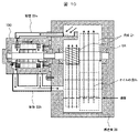
図9に示すように、本実施例の減速機20は、車両駆動モータ10Bの出力側に接続した装置であり、複数の歯車21を組み合わせることで、車両駆動モータ10Bの出力シャフト4の低トルク高速回転の出力を、高トルク低速回転の駆動力に変換するものである。
この減速機20において、歯車21群が下方の貯油部から巻き上げた低温のオイルは、配管22aを通って車両駆動モータ10Bの上通油路2aに供給され、また、車両駆動モータ10Bの下通油路2bから排出された高温のオイルは配管22bを通って減速機20に循環する。そして、車両駆動モータ10Bから減速機20に戻った高温のオイルは、減速機20の下方の貯油部で放熱され、低温になる。
ここで、減速機20の歯車21のうち、車両駆動モータ10Bの出力シャフト4と同軸のものは、出力シャフト4と等速で高速回転する。この歯車21が、例えば、はすば歯車であれば、その歯車21のシャフトを支持する軸受6Aは、径方向および軸方向の荷重を受けるため、車両駆動モータ10Bの軸受6より過酷な条件下で使用される可能性がある。そのため、本実施例では、減速機20の軸受6Aに対しても、実施例1や実施例2と同様のオイル保持部9Dを設置した。
図10はステータコイル3の左右の端部において、発熱量が異なる場合の例である。本例は左側端部の発熱量が大きい場合を示しており、配管22aはステータコイル3左側端部近傍に接続されている。本構造によって発熱量の大きい側のコイルをより冷却することが可能となる。
これにより、上記実施例の車両駆動モータ10A、10Bと同様に、本実施例の減速機20においても、電気自動車を長期間運転しなかった場合でも、減速機の軸受の潤滑を維持することができる。
10、10A、10B…車両駆動モータ、1…ケーシング、1a…フロントケーシング、1b…円筒ケーシング、1c…リアケーシング、2…通油路、2a…上通油路、2b…下通油路、3…ステータコイル、3a…端部、4…出力シャフト、5…ロータ、6…軸受、7…リテーナ、8…ボルト、8a…ボルト穴、9…オイル保持部、20…減速機、21…歯車、22…配管
Claims (5)
- 内周面に円筒形状のステータコイルを固定し、上部に通油路を設けたケーシングと、
該ケーシング内に配置され、前記ステータコイルの対向位置にロータを固定した出力シャフトと、
前記出力シャフトを支持する軸受と、
該軸受と対向配置され、前記通油路から供給されたオイルを貯えるオイル保持部と、を備え、
前記オイル保持部は、前記出力シャフトの軸方向から正面視したときに、上辺が前記出力シャフトの下端より低く、下辺が前記軸受の下外周に沿ったポケット形状の受皿である車両駆動モータ。 - 請求項1に記載の車両駆動モータにおいて、
前記オイル保持部は、前記出力シャフトの軸方向から正面視したときに、前記出力シャフトの外周を囲み、上端高さが前記出力シャフトの中心高さと略等しい、略U字状の受皿であることを特徴とする車両駆動モータ。 - 請求項1に記載の車両駆動モータにおいて、
前記オイル保持部は、前記出力シャフトの軸方向から正面視したときに、前記出力シャフトの外周を囲み、上端高さが前記出力シャフトの中心高さと略等しい、略三日月状の受皿であることを特徴とする車両駆動モータ。 - 請求項1から請求項3の何れか一項に記載の車両駆動モータにおいて、
前記オイル保持部を、前記軸受の軸方向の移動を制限するリテーナと一体に構成したことを特徴とする車両駆動モータ。 - 請求項1から請求項3の何れか一項に記載の車両駆動モータにおいて、
前記出力シャフトは、一対の軸受で支持されており、各々の軸受に対し、前記オイル保持部が設けられていることを特徴とする車両駆動モータ。
Priority Applications (3)
| Application Number | Priority Date | Filing Date | Title |
|---|---|---|---|
| DE112021005650.6T DE112021005650T5 (de) | 2021-03-22 | 2021-09-13 | Fahrzeug-antriebsmotor |
| CN202180089744.3A CN116685785A (zh) | 2021-03-22 | 2021-09-13 | 车辆驱动电动机 |
| US18/273,124 US20240128828A1 (en) | 2021-03-22 | 2021-09-13 | Vehicle Drive Motor |
Applications Claiming Priority (2)
| Application Number | Priority Date | Filing Date | Title |
|---|---|---|---|
| JP2021-047126 | 2021-03-22 | ||
| JP2021047126A JP7474215B2 (ja) | 2021-03-22 | 2021-03-22 | 車両駆動モータ |
Publications (1)
| Publication Number | Publication Date |
|---|---|
| WO2022201590A1 true WO2022201590A1 (ja) | 2022-09-29 |
Family
ID=83396685
Family Applications (1)
| Application Number | Title | Priority Date | Filing Date |
|---|---|---|---|
| PCT/JP2021/033454 Ceased WO2022201590A1 (ja) | 2021-03-22 | 2021-09-13 | 車両駆動モータ |
Country Status (5)
| Country | Link |
|---|---|
| US (1) | US20240128828A1 (ja) |
| JP (1) | JP7474215B2 (ja) |
| CN (1) | CN116685785A (ja) |
| DE (1) | DE112021005650T5 (ja) |
| WO (1) | WO2022201590A1 (ja) |
Cited By (1)
| Publication number | Priority date | Publication date | Assignee | Title |
|---|---|---|---|---|
| FR3156613A1 (fr) | 2023-12-06 | 2025-06-13 | Valeo Eautomotive Germany Gmbh | Groupe moteur et engin de mobilité comportant un tel groupe moteur |
Families Citing this family (5)
| Publication number | Priority date | Publication date | Assignee | Title |
|---|---|---|---|---|
| US20260155686A1 (en) * | 2021-11-08 | 2026-06-04 | Hitachi Astemo, Ltd. | Rotating electric machine |
| US20260084120A1 (en) | 2022-09-14 | 2026-03-26 | Kagoshima University | Bubble generation device, bubble generation method, and method of producing bubble generating member |
| EP4686857A1 (en) * | 2024-07-29 | 2026-02-04 | Deere & Company | Arrangement for lubrication |
| JP2026111110A (ja) | 2024-12-23 | 2026-07-03 | 大同メタル工業株式会社 | 車両駆動モータの回転軸用のすべり軸受 |
| JP7886397B1 (ja) | 2024-12-23 | 2026-07-07 | 大同メタル工業株式会社 | 車両駆動モータの回転軸用のすべり軸受 |
Citations (2)
| Publication number | Priority date | Publication date | Assignee | Title |
|---|---|---|---|---|
| JP2013135577A (ja) * | 2011-12-27 | 2013-07-08 | Toyota Industries Corp | 回転電機の冷却構造 |
| WO2017203562A1 (ja) * | 2016-05-23 | 2017-11-30 | 三菱電機株式会社 | 回転電機 |
Family Cites Families (11)
| Publication number | Priority date | Publication date | Assignee | Title |
|---|---|---|---|---|
| US865083A (en) * | 1901-04-11 | 1907-09-03 | Niels Anton Christensen | Lubricating mechanism. |
| JP2572699B2 (ja) * | 1992-06-04 | 1997-01-16 | 株式会社荏原製作所 | 回転機械の軸受潤滑構造 |
| US8508090B2 (en) | 2010-02-19 | 2013-08-13 | Toyota Jidosha Kabushiki Kaisha | Lubrication structure of power transmission apparatus |
| US9458923B2 (en) * | 2011-03-31 | 2016-10-04 | Textron Innovations Inc. | Gearbox with passive lubrication system |
| KR102063727B1 (ko) * | 2013-11-05 | 2020-01-08 | 현대모비스 주식회사 | 오일 냉각 방식 모터용 냉각 구조 |
| JP2015231275A (ja) * | 2014-06-04 | 2015-12-21 | Ntn株式会社 | インホイールモータ駆動装置 |
| WO2017041026A1 (en) * | 2015-09-02 | 2017-03-09 | Nidec Motor Corporation | Motor bearing lubrication arrangement |
| JP2017118688A (ja) * | 2015-12-24 | 2017-06-29 | 三菱自動車工業株式会社 | モータ |
| EP3672035B1 (en) * | 2018-12-19 | 2022-02-23 | LG Magna e-Powertrain Co., Ltd. | Motor |
| CN110492663B (zh) * | 2019-07-08 | 2021-02-23 | 华为技术有限公司 | 电机、动力总成和汽车 |
| JP7671157B2 (ja) * | 2021-03-08 | 2025-05-01 | ニデック株式会社 | 駆動装置 |
-
2021
- 2021-03-22 JP JP2021047126A patent/JP7474215B2/ja active Active
- 2021-09-13 WO PCT/JP2021/033454 patent/WO2022201590A1/ja not_active Ceased
- 2021-09-13 CN CN202180089744.3A patent/CN116685785A/zh active Pending
- 2021-09-13 US US18/273,124 patent/US20240128828A1/en active Pending
- 2021-09-13 DE DE112021005650.6T patent/DE112021005650T5/de active Pending
Patent Citations (2)
| Publication number | Priority date | Publication date | Assignee | Title |
|---|---|---|---|---|
| JP2013135577A (ja) * | 2011-12-27 | 2013-07-08 | Toyota Industries Corp | 回転電機の冷却構造 |
| WO2017203562A1 (ja) * | 2016-05-23 | 2017-11-30 | 三菱電機株式会社 | 回転電機 |
Cited By (1)
| Publication number | Priority date | Publication date | Assignee | Title |
|---|---|---|---|---|
| FR3156613A1 (fr) | 2023-12-06 | 2025-06-13 | Valeo Eautomotive Germany Gmbh | Groupe moteur et engin de mobilité comportant un tel groupe moteur |
Also Published As
| Publication number | Publication date |
|---|---|
| CN116685785A (zh) | 2023-09-01 |
| JP2022146253A (ja) | 2022-10-05 |
| US20240128828A1 (en) | 2024-04-18 |
| DE112021005650T5 (de) | 2023-08-10 |
| JP7474215B2 (ja) | 2024-04-24 |
Similar Documents
| Publication | Publication Date | Title |
|---|---|---|
| JP2022146253A (ja) | 車両駆動モータ | |
| JP7086271B2 (ja) | 冷却作用を備えた電気駆動装置 | |
| JP4538253B2 (ja) | モータ式動力装置 | |
| US20200282828A1 (en) | Vehicle driving apparatus | |
| US20230067898A1 (en) | Drive apparatus | |
| JP5957879B2 (ja) | 回転電機の冷却構造 | |
| US7160086B2 (en) | Rotary machine cooling system | |
| JP4218129B2 (ja) | 油圧発生装置及びそれを用いたハイブリッド車輌 | |
| JP3011088B2 (ja) | 始動兼発電装置 | |
| CN104838157B (zh) | 具有改善轴承润滑的旋转电机及其相关方法 | |
| JP2010203493A (ja) | 車両の動力伝達装置 | |
| EP2724450A2 (en) | Cooling structure of rotary electric machine | |
| JP5256834B2 (ja) | 電動ユニット | |
| JP2009063043A (ja) | インホイールモータ駆動装置 | |
| JPWO2011101911A1 (ja) | 動力伝達装置の潤滑構造 | |
| JP2012191718A (ja) | 永久磁石式発電電動機および油圧ショベル用永久磁石式発電電動機 | |
| JP2009195082A (ja) | ステータの冷却構造 | |
| JP2024145695A (ja) | 駆動装置 | |
| CN114825775B (zh) | 包括带有湿空间的冷却和/或润滑系统的电机、带有电机的机动车辆 | |
| JP2018038099A (ja) | 電動モータ | |
| JP2018014857A (ja) | 電動モータの冷却構造 | |
| CN109538632A (zh) | 一种航空泵浸油电机用轴瓦及航空泵浸油电机 | |
| JP2016201900A (ja) | 電動機の支持装置 | |
| JP7777942B2 (ja) | 駆動装置 | |
| JP6812050B1 (ja) | コアレスモータ及び発電機 |
Legal Events
| Date | Code | Title | Description |
|---|---|---|---|
| 121 | Ep: the epo has been informed by wipo that ep was designated in this application |
Ref document number: 21933190 Country of ref document: EP Kind code of ref document: A1 |
|
| WWE | Wipo information: entry into national phase |
Ref document number: 202180089744.3 Country of ref document: CN |
|
| WWE | Wipo information: entry into national phase |
Ref document number: 18273124 Country of ref document: US |
|
| 122 | Ep: pct application non-entry in european phase |
Ref document number: 21933190 Country of ref document: EP Kind code of ref document: A1 |