WO2022201528A1 - レーザ加工装置 - Google Patents
レーザ加工装置 Download PDFInfo
- Publication number
- WO2022201528A1 WO2022201528A1 PCT/JP2021/013022 JP2021013022W WO2022201528A1 WO 2022201528 A1 WO2022201528 A1 WO 2022201528A1 JP 2021013022 W JP2021013022 W JP 2021013022W WO 2022201528 A1 WO2022201528 A1 WO 2022201528A1
- Authority
- WO
- WIPO (PCT)
- Prior art keywords
- outside air
- housing
- air intake
- processing apparatus
- laser processing
- Prior art date
- Legal status (The legal status is an assumption and is not a legal conclusion. Google has not performed a legal analysis and makes no representation as to the accuracy of the status listed.)
- Ceased
Links
Images







Classifications
-
- B—PERFORMING OPERATIONS; TRANSPORTING
- B23—MACHINE TOOLS; METAL-WORKING NOT OTHERWISE PROVIDED FOR
- B23K—SOLDERING OR UNSOLDERING; WELDING; CLADDING OR PLATING BY SOLDERING OR WELDING; CUTTING BY APPLYING HEAT LOCALLY, e.g. FLAME CUTTING; WORKING BY LASER BEAM
- B23K26/00—Working by laser beam, e.g. welding, cutting or boring
- B23K26/12—Working by laser beam, e.g. welding, cutting or boring in a special environment or atmosphere, e.g. in an enclosure
- B23K26/127—Working by laser beam, e.g. welding, cutting or boring in a special environment or atmosphere, e.g. in an enclosure in an enclosure
-
- B—PERFORMING OPERATIONS; TRANSPORTING
- B23—MACHINE TOOLS; METAL-WORKING NOT OTHERWISE PROVIDED FOR
- B23K—SOLDERING OR UNSOLDERING; WELDING; CLADDING OR PLATING BY SOLDERING OR WELDING; CUTTING BY APPLYING HEAT LOCALLY, e.g. FLAME CUTTING; WORKING BY LASER BEAM
- B23K26/00—Working by laser beam, e.g. welding, cutting or boring
- B23K26/36—Removing material
- B23K26/38—Removing material by boring or cutting
-
- B—PERFORMING OPERATIONS; TRANSPORTING
- B23—MACHINE TOOLS; METAL-WORKING NOT OTHERWISE PROVIDED FOR
- B23K—SOLDERING OR UNSOLDERING; WELDING; CLADDING OR PLATING BY SOLDERING OR WELDING; CUTTING BY APPLYING HEAT LOCALLY, e.g. FLAME CUTTING; WORKING BY LASER BEAM
- B23K26/00—Working by laser beam, e.g. welding, cutting or boring
- B23K26/14—Working by laser beam, e.g. welding, cutting or boring using a fluid stream, e.g. a jet of gas, in conjunction with the laser beam; Nozzles therefor
- B23K26/142—Working by laser beam, e.g. welding, cutting or boring using a fluid stream, e.g. a jet of gas, in conjunction with the laser beam; Nozzles therefor for the removal of by-products
-
- B—PERFORMING OPERATIONS; TRANSPORTING
- B23—MACHINE TOOLS; METAL-WORKING NOT OTHERWISE PROVIDED FOR
- B23K—SOLDERING OR UNSOLDERING; WELDING; CLADDING OR PLATING BY SOLDERING OR WELDING; CUTTING BY APPLYING HEAT LOCALLY, e.g. FLAME CUTTING; WORKING BY LASER BEAM
- B23K26/00—Working by laser beam, e.g. welding, cutting or boring
- B23K26/16—Removal of by-products, e.g. particles or vapours produced during treatment of a workpiece
-
- B—PERFORMING OPERATIONS; TRANSPORTING
- B23—MACHINE TOOLS; METAL-WORKING NOT OTHERWISE PROVIDED FOR
- B23K—SOLDERING OR UNSOLDERING; WELDING; CLADDING OR PLATING BY SOLDERING OR WELDING; CUTTING BY APPLYING HEAT LOCALLY, e.g. FLAME CUTTING; WORKING BY LASER BEAM
- B23K26/00—Working by laser beam, e.g. welding, cutting or boring
- B23K26/70—Auxiliary operations or equipment
- B23K26/702—Auxiliary equipment
-
- B—PERFORMING OPERATIONS; TRANSPORTING
- B23—MACHINE TOOLS; METAL-WORKING NOT OTHERWISE PROVIDED FOR
- B23K—SOLDERING OR UNSOLDERING; WELDING; CLADDING OR PLATING BY SOLDERING OR WELDING; CUTTING BY APPLYING HEAT LOCALLY, e.g. FLAME CUTTING; WORKING BY LASER BEAM
- B23K26/00—Working by laser beam, e.g. welding, cutting or boring
- B23K26/70—Auxiliary operations or equipment
- B23K26/702—Auxiliary equipment
- B23K26/706—Protective screens
Definitions
- the present disclosure relates to a laser processing apparatus that irradiates a laser beam to process a workpiece.
- Patent Document 1 discloses a movable stage having a workpiece installation area for installing a workpiece to be cut, and a laser oscillator having a laser emission surface arranged to face the workpiece installation area and emitting a laser beam. , a cover member covering a laser irradiation space between a laser emission surface and a workpiece setting area, and a dust collection pump.
- the cover member of the laser cutting device described in Patent Document 1 has an intake port and an exhaust port.
- the intake port is provided at a position closer to the work installation area than the laser emission surface on the side surface of the cover member.
- the exhaust port is provided at a position closer to the workpiece installation area than the laser emission surface on the opposite side across the workpiece installation area, and is connected to the dust collection pump.
- An object of the present invention is to obtain a laser processing apparatus capable of forming a flow.
- the laser processing apparatus includes a housing, a processing table, a portal, a processing head, a loading/unloading door, an exhaust port, and an outside air intake.
- An inlet and a deflection section are provided. Three directions orthogonal to each other are defined as a first direction, a second direction, and a third direction.
- the housing is arranged on the floor surface in the room, and has first and second surfaces orthogonal to the first direction, third and fourth surfaces orthogonal to the second direction, and orthogonal to the third direction, It has a fifth surface facing the surface.
- the processing table is arranged inside the housing, on which a workpiece is placed, and has a table surface parallel to the floor surface.
- the portal has a column base portion provided on at least one of both sides of the processing table in the second direction, and a beam portion connected to the column base portion and extending in the second direction above the processing table.
- the processing head is supported by the beam and emits laser light.
- the loading/unloading door is an openable/closable door used when loading/unloading the workpiece provided on the first surface.
- the exhaust port is provided on the second surface and is connected to an exhaust section that generates an airflow that is the flow of air inside the housing.
- the outside air intake is provided in the upper part of the housing on the first surface side in the first direction with respect to the processing head, and takes in outside air, which is air outside the housing.
- the deflector guides outside air introduced from the outside air intake toward the machining head.
- the machining head exists on the second surface side of the outside air intake at all positions in the movable range.
- the laser processing apparatus can form an exhaust flow that stably discharges dust generated at a processing point when processing a three-dimensional workpiece having unevenness by irradiating it with a laser beam. It has the effect of being able to
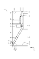
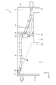
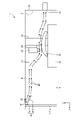
- FIG. 1 is a see-through perspective view showing an example of the configuration of a laser processing apparatus according to Embodiment 1.
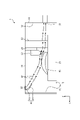
- FIG. FIG. 4 is a cross-sectional view showing an example of exhaust flow in the housing of the laser processing apparatus according to Embodiment 1;
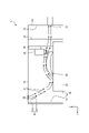
- FIG. 4 is a cross-sectional view showing another example of the flow of exhaust gas in the housing of the laser processing apparatus according to Embodiment 1;
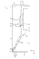
- FIG. 2 is a cross-sectional view showing an example of an arrangement position of an outside air intake port in the laser processing apparatus according to Embodiment 1;
- FIG. 2 is a cross-sectional view showing another example of the configuration of the laser processing apparatus according to Embodiment 1;
- FIG. 2 is a cross-sectional view showing another example of the configuration of the laser processing apparatus according to Embodiment 1; Sectional view showing an example of the configuration of a laser processing apparatus according to Embodiment 2
- FIG. 5 is a cross-sectional view schematically showing movement of the portal in the laser processing apparatus according to the second embodiment;
- FIG. 5 is a cross-sectional view schematically showing movement of the portal in the laser processing apparatus according to the second embodiment;
- FIG. 4 is a diagram showing an example of an exhaust flow inside a housing of a laser processing apparatus without a restricting portion;
- FIG. 10 is a diagram showing another example of the flow of exhaust gas inside the housing of the laser processing apparatus without the restrictor.
- Sectional view showing an example of the configuration of a laser processing apparatus according to Embodiment 5 FIG. 11 is a diagram showing an example of the state of exhaust gas flow around the processing head in the laser processing apparatus according to Embodiment 4;
- FIG. 12 is a diagram showing an example of the flow of exhaust gas around the processing head in the laser processing apparatus according to Embodiment 5;
- Cross-sectional view showing an example of the arrangement position of the restricting portion in the laser processing apparatus according to Embodiment 5
- FIG. 1 is a see-through perspective view showing an example of the configuration of a laser processing apparatus according to Embodiment 1.
- the two axes orthogonal to each other in the horizontal plane are the X-axis and the Y-axis, and the axis perpendicular to both the X-axis and the Y-axis is the Z-axis.
- two relative positions along the X-axis are denoted using front and back
- two relative positions along the Y-axis are denoted using left and right
- two relative positions along the Z-axis are denoted using front and back.
- Positions are indicated using top and bottom.
- the X-axis direction corresponds to the first direction
- the Y-axis direction corresponds to the second direction
- the Z-axis direction corresponds to the third direction.
- the laser processing device 1 has a housing 10 .
- the housing 10 has a hollow shape with six surfaces: a front surface 11 and a rear surface 12 orthogonal to the X-axis direction, a left surface 13 and a right surface 14 orthogonal to the Y-axis direction, and a lower surface 15 and an upper surface 16 orthogonal to the Z-axis direction.
- the housing 10 is, for example, a hollow hexahedral shape.
- a case in which the housing 10 has a hollow rectangular parallelepiped shape extending in the X-axis direction more than in the Y-axis direction will be taken as an example.
- the front surface 11 corresponds to the first surface
- the rear surface 12 corresponds to the second surface
- the left surface 13 corresponds to the third surface
- the right surface 14 corresponds to the fourth surface
- the upper surface 16 corresponds to the fifth surface. corresponds to the surface.
- the front face 11 is an openable loading/unloading door 11a used when loading or unloading the workpiece 51 .
- the entire front surface 11 is the loading/unloading door 11a, but a part of the front surface 11 may be configured by the loading/unloading door 11a.
- the laser processing apparatus 1 shown in Embodiment 1 is intended to process an object 51 up to, for example, several meters in length. Therefore, an example of the length of the processing table 21 is about 1 m or more and 7 m or less.
- the laser processing apparatus 1 includes a processing table 21, a processing head 22, and a portal 23 inside a housing 10.
- the processing table 21 is arranged on the lower surface 15 inside the housing 10 , and has a table surface parallel to the lower surface 15 on which a workpiece 51 to be laser-processed is placed.
- the processing table 21 similarly to the case 10, has a shape in which the length in the X-axis direction is longer than the length in the Y-axis direction.
- the machining table 21 is movable in the X-axis direction, which is the longitudinal direction. That is, a drive system (not shown) is provided for moving the machining table 21 in the X-axis direction.
- the workpiece 51 is loaded onto the processing table 21 inside the housing 10 through the loading/unloading door 11 a arranged on the front surface 11 of the housing 10 .
- the processing head 22 condenses and irradiates a laser beam transmitted from a laser oscillator (not shown) to a processing point where the workpiece 51 is processed.
- the processing head 22 processes the workpiece 51 into an arbitrary shape by changing the relative position with the workpiece 51 .
- transmission from the laser oscillator to the processing head 22 is generally transmitted through a plurality of mirrors.
- a fiber laser, disk laser, or direct diode laser that oscillates at a wavelength that can be transmitted through an optical fiber is used as the laser oscillator, an optical fiber for optical transmission is generally used.
- the portal 23 is arranged so as to straddle the processing table 21 .
- the portal 23 has a pair of column bases 231 extending in a direction perpendicular to the lower surface 15 and a beam 232 connecting the ends of the pair of column bases 231 on the upper surface 16 side.
- the beam portion 232 extends in the Y-axis direction above the processing table 21 .
- the beam portion 232 is provided with the processing head 22 .
- the machining head 22 is connected to the beam portion 232 via the support member 24 .
- the support member 24 supports the processing head 22 so as to be movable in the Z-axis direction and the Y-axis direction. That is, the support member 24 is provided with a drive system (not shown) for moving the machining head 22 in the Z-axis direction and the Y-axis direction.
- the laser processing apparatus 1 includes an exhaust port 31 and an outside air intake port 32 in the housing 10 .
- the exhaust port 31 is provided on the rear surface 12 of the housing 10 and connected to an exhaust section (not shown). In one example, the exhaust port 31 is provided at substantially the same position as the upper surface of the processing table 21 in the Z-axis direction.
- the exhaust unit generates an airflow that is the flow of air inside the housing 10 .
- the outside air intake port 32 is provided in the upper part of the housing 10 on the front face 11 side in the X-axis direction with respect to the machining head 22 . That is, the machining head 22 exists on the rear surface 12 side of the outside air intake 32 at all positions in the movable range of the machining head 22 . In the example of FIG.
- the outside air intake port 32 is provided at the end of the top surface 16 of the housing 10 on the loading/unloading door 11 a side, and takes in the outside air, which is the gas outside the housing 10 , into the housing 10 .
- An example gas is air.
- the laser processing device 1 includes a deflector 41 and a light shielding plate 42 .
- the deflector 41 guides the outside air taken into the housing 10 toward the machining head 22 .
- the light shielding plate 42 prevents the scattered light of the laser light from the processing head 22 from leaking from the outside air intake 32, or sufficiently attenuates the scattered light of the laser light leaking from the outside air intake 32. It is provided in the vicinity of the outside air intake 32 so as to surround the outside air intake 32 .
- the light shielding plate 42 is arranged on the front surface 11 side, the left surface 13 side, and the right surface 14 side of the rectangular outside air intake 32 so as to stand at a vertical or near-perpendicular angle to the upper surface 16 of the housing 10. It is a plate-like member.
- the relative positions of the machining head 22 and the workpiece 51 are changed as follows. In the front-rear direction, the relative position between the workpiece 51 placed on the machining table 21 and the machining head 22 that emits the laser beam is changed by moving or extending the machining table 21 that supports the workpiece 51. can be made Further, the support member 24 fixing the processing head 22 may be provided with one or more rotating mechanisms for rotating the processing head 22 in order to change the incident angle of the laser beam with respect to the workpiece 51 .
- the processing point When the workpiece 51 is processed by irradiating it with laser light, the processing point emits reflected light or scattered light of the laser light, or processing light from the processed substance or plasma of the processing gas. be.
- dust and the like made of the material, melted material, oxide, etc. of the material constituting the workpiece 51 are generated and float in the air.
- the dust contains conductive fibers such as carbon fibers. If such floating fine conductive fibers adhere to an electrical substrate such as a control device and a power supply device (not shown) of the laser processing apparatus 1, a short circuit occurs in the circuit on the electrical substrate. malfunction or damage.
- the processing table 21 including the processing point, the processing head 22, the portal 23, and the like are installed so as to be entirely covered inside the housing 10, which is a cover.
- the dust may leak out of the housing 10.
- it is required to form a unidirectional exhaust flow through the processing point to the exhaust port 31 .
- the outside air intake port 32 is installed on the upper surface 16 near the work point, the flow does not flow in one direction passing through the work point, but forms a stagnation at the work point and spreads inside the housing 10. Become. With such a configuration, dust will be diffused into the housing 10 and deposited on the lower surface 15 within the housing 10 . In this case, when the workpiece 51 is placed on or removed from the processing table 21, dust may be blown up.
- FIG. 2 is a cross-sectional view showing an example of exhaust flow in the housing of the laser processing apparatus according to Embodiment 1.
- FIG. According to the configuration of the first embodiment, outside air taken into the housing 10 from the outside air intake port 32 of the upper surface 16 on the loading/unloading door 11a side passes through the processing point in one direction and is directed toward the exhaust port 31.
- An exhaust flow EF is formed that flows downward from the upper surface 16 to the machining point. That is, the rear surface 12, which is the surface facing the loading/unloading door 11a, is sucked to the exhaust port 31 connected to the exhaust part, and the outside air intake port 32 is the loading/unloading door closer to the loading/unloading door 11a than the processing point. It is installed on the upper surface 16 in the vicinity of 11a.
- the outside air intake 32 is installed on the upper surface 16 of the housing 10, even if the reflected light or scattered light of the laser beam on the workpiece 51 or the machining light generated at the machining point leaks from the outside air intake 32. Even if there is such a thing, the reflected light, scattered light, or processed light reaches the worker outside the housing 10 via the ceiling of the room in which the housing 10 is installed. That is, the reflected light, scattered light, or processed light is scattered and sufficiently attenuated from the inside of the housing 10 to the position of the operator via the outside air intake 32 .
- the light shielding plate 42 attenuates reflected light, scattered light, or processed light by reflection and scattering.
- reflected light, scattered light, or processed light can be substantially confined inside the housing 10, and a safe environment can be provided for workers working outside the housing 10.
- the outside air intake port 32 for taking in outside air and blocking light in the laser processing apparatus 1 can be configured in a simple shape.
- the outside air intake port 32 is installed in the vicinity of the loading/unloading door 11a of the upper surface 16 in this way, the exhaust flow EF can be supplied to the processing point in a downward flow.
- the shape of the workpiece 51 closer to the carry-in/out door 11a than the machining head 22 prevents the exhaust flow EF from being obstructed, thereby preventing dust generated at the machining point. It can be exhausted and recovered.
- the deflector 41 includes a flat plate-like first portion 411 extending from the upper surface 16 toward the lower surface 15 and a flat plate extending from the end of the first portion 411 on the lower surface 15 side toward the processing head 22 . and a shaped second portion 412 .
- the deflecting portion 41 may be composed of one plate, or may have a partially curved surface.
- the angle ⁇ between the inclined surface of the second portion 412 of the deflection section 41 and the upper surface 16 of the housing 10 is between 25 degrees and 50 degrees, for example, depending on the positional relationship between the position of the deflection section 41 and the processing area. set.
- the deflector 41 may be configured by a part of the inner surface of the housing 10 including the upper surface 16 .
- the width of the deflection portion 41 in the Y-axis direction should be longer than the width of the outside air intake 32 in the Y-axis direction. It is preferable that the width is about 10% longer than the width of the outside air intake 32 in the Y-axis direction.
- the deflector 41 may reach from the left surface 13 to the right surface 14 of the housing 10 .
- the length of the deflector 41 in the X-axis direction the outside air introduced into the housing 10 from the outside air intake 32 spreads in the housing 10 and reaches the deflector 41. is longer than the length in the X-axis direction. That is, it is sufficient that the projected portion of the deflection portion 41 projected onto the upper surface 16 includes the outside air intake port 32 .
- the length can be several times the length of the outside air intake 32 in the X-axis direction. It should be noted that the longer the length of the deflecting portion 41 in the X-axis direction, the longer the distance along the flow, and the more controllable the flow is directed toward the machining point.
- FIG. 1 illustrates a case where the housing 10 has a rectangular parallelepiped shape
- the housing 10 of Embodiment 1 is not limited to a rectangular parallelepiped shape.
- the housing 10 may have a substantially hexahedral structure as long as the effects of the first embodiment are achieved, that is, as long as the dust can be effectively exhausted and collected.
- the corners of the housing 10 may be chamfered, or the corners of the housing 10 may be curved.
- the front surface 11, the rear surface 12, the left surface 13, the right surface 14, or the upper surface 16 of the housing 10 may be provided with projections or curved surfaces.
- FIG. 3 is a cross-sectional view showing another example of the flow of exhaust gas in the housing of the laser processing apparatus according to Embodiment 1.
- FIG. 3 the position of the processing table 21 is different from that in FIG.
- FIG. 3 shows the laser processing apparatus 1 in which the light shielding plate 42 is not provided.
- the exhaust flow EF near the machining point is a downward flow, but becomes more horizontal. In this manner, the flow can be directed toward the exhaust port 31 in one direction with respect to the entire processing table 21 .
- the inclined surface of the second portion 412 of the deflection section 41 and the upper surface 16 is set to be large, for example, 70 degrees or more. As a result, the exhaust flow EF in the vicinity of the machining point becomes a downward flow with a greater inclination with respect to the machining point.
- FIG. 4 is a cross-sectional view showing an example of an arrangement position of an outside air intake in the laser processing apparatus according to Embodiment 1.
- FIG. 4 the position of the outside air intake 32 is closer to the loading/unloading door 11a than to the processing head 22, and is closer to the loading/unloading door 11a than the end face 21a of the processing table 21 on the loading/unloading door 11a side. is preferred.
- the position of the outside air intake 32 is defined by a straight line L1 drawn from the machining head 22 onto the machining table 21, a straight line L2 formed by connecting a point P where the straight line L1 intersects the surface of the machining table 21 to the outside air intake 32, It is preferable that the upper surface 16 on the loading/unloading door 11a side has an angle A of 30 degrees or more. Furthermore, by positioning the outside air intake port 32 at a position where the angle A is 40 degrees or more, the angle formed by the inclination of the exhaust flow EF with respect to the machining point and the upper surface 16 can be suppressed to 50 degrees or less. As a result, it can be seen that a unidirectional flow toward the exhaust port 31 can be formed for the entire processing table 21 inside the housing 10 without forming a large stagnation on the surface of the workpiece 51 .
- FIG. 5 is a cross-sectional view showing another example of the configuration of the laser processing apparatus according to Embodiment 1.
- FIG. The laser processing apparatus 1 shown in FIG. 5 differs from those shown in FIGS. 1 and 2 in the position of the outside air intake port 32 . 1 and 2, the outside air intake port 32 is installed on the upper surface 16 in the vicinity of the loading/unloading door 11a, but in FIG. be. Even at such a position of the outside air intake port 32, a unidirectional exhaust flow EF from the processing point toward the exhaust port 31 is formed. Since other configurations are the same as those in FIGS. 1 and 2, description thereof will be omitted.
- the deflection section 41 is composed of one member, but may be composed of a plurality of members. In this case, a plurality of members are arranged parallel to each other in the X-axis direction in a region including the outside air intake port 32 of the upper surface 16 inside the housing 10 .
- 6 is a cross-sectional view showing another example of the configuration of the laser processing apparatus according to Embodiment 1.
- the deflection section 41 is composed of three members.
- the deflecting portion 41 includes a pair of members provided along the Y-axis direction side of the outside air intake 32 at intervals in the X-axis direction, and 1 provided near the central portion of the outside air intake 32 between the pair of members. and a member.
- a parallel flow path is formed by the three members. Since other configurations are the same as those in FIGS. 1 and 2, description thereof will be omitted. In this case, the directivity of the exhaust gas flow EF can be made higher than in the case of FIGS. 1 and 2, so the flow can be guided more accurately in the direction of the machining point.
- FIG. 6 shows the case where the deflection section 41 has two parallel flow paths, it may have three or more parallel flow paths.
- the deflector 41 is provided inside the housing 10 , but may be provided outside the housing 10 at the outside air intake 32 .
- the deflector 41 is installed outside the outside air intake 32 so as to form an angle between 25 degrees and 50 degrees with respect to the upper surface 16 of the housing 10 . Similar effects can also be achieved by this.
- the deflector 41 in this case as in the case of FIGS. It can also be used as a tube.
- a structure can be adopted in which outside air introduced into the housing 10 is blown into the housing 10 after passing through this pipe.
- the member of the upper surface 16 may be formed with a channel having a desired inclination.
- the laser processing apparatus 1 of Embodiment 1 includes a hexahedral housing 10 having a front surface 11, a rear surface 12, a left surface 13, a right surface 14, a lower surface 15 and an upper surface 16, and a processing table 21 arranged in the housing 10. and a portal 23 arranged to straddle the processing table 21 in the housing 10 and movably supporting the processing head 22 .
- the front surface 11 of the housing 10 is a loading/unloading door 11a, and the housing 10 has an outside air intake port 32 on the loading/unloading door 11a side of the top surface 16, and an exhaust unit on the rear surface 12 facing the front surface 11. It has an exhaust port 31 to which it is connected.
- the laser processing apparatus 1 has a deflector 41 on the upper surface 16 near the outside air intake 32 inside the housing 10 for guiding the outside air to the vicinity of the processing point.
- the entire movable range of the machining head 22 exists on the rear surface 12 side of the outside air intake 32 .
- outside air can be supplied from the outside air intake port 32 obliquely above the machining point, so outside air can be supplied to the machining point without being blocked by the workpiece 51 . That is, it is possible to form an exhaust flow EF that stably discharges dust generated at the processing point when the three-dimensional workpiece 51 having unevenness is irradiated with the laser beam for processing.
- Embodiment 1 even if reflected light, scattered light, or processed light is emitted from the outside air intake port 32 to the outside, it is scattered by the ceiling in the room where the housing 10 is provided, and a worker outside the housing 10 is disturbed. to reach However, the reflected, scattered or processed light is sufficiently attenuated by the time it reaches the operator. Therefore, the outside air intake port 32 has a light shielding function, and it is possible to cope with leakage of reflected light, scattered light, or processing light without forming a complicated shape on the housing 10 for taking in the outside air. can. In addition, since the housing 10 does not have a complicated shape for blocking light, the loading/unloading door 11a for loading/unloading the large workpiece 51 into and out of the processing area can be arranged in the housing 10 .
- the external air intake port 32 is provided in the upper surface 16 of the rectangular parallelepiped housing 10 so that the exhaust flow EF flows along the longitudinal direction inside the housing 10 . Therefore, unlike the laser cutting apparatus described in Patent Document 1, dust generated by laser processing can be exhausted without requiring a wider space for the outside air intake port 32 . Moreover, even if the portal 23 is arranged, since the outside air is introduced from the upper surface 16 of the housing 10, the portal 23 does not interfere with the exhaust flow EF. Furthermore, since the portal 23 is installed in the direction straddling the short direction of the processing table 21, it can be made smaller than when it is installed in the direction straddling the longitudinal direction.
- Embodiment 2 the workpiece 51 on the machining table 21 is moved with respect to the machining head 22 by moving or extending the machining table 21 in the X-axis direction.
- Embodiment 2 a case of moving the portal 23 that supports the machining head 22 will be described.
- FIG. 7 is a cross-sectional view showing an example of the configuration of a laser processing apparatus according to Embodiment 2.
- symbol is attached
- the portal 23 is movable in the X-axis direction. That is, the portal 23 is provided with a drive system (not shown), and the drive system moves the portal 23 in the X-axis direction.
- outside air from the outside air intake port 32 hits a predetermined position on the processing table 21, and then flows along the surface of the workpiece 51 toward the exhaust port 31 in one direction. of the exhaust flow EF.
- FIGS. 8 and 9 are cross-sectional views schematically showing movement of the portal in the laser processing apparatus according to Embodiment 2.
- FIG. As shown in FIGS. 7 to 9, even if the portal die 23 moves and the position of the processing head 22 moves, there is a processing point in the exhaust flow EF where the laser beam is irradiated onto the workpiece 51. Since it exists, it is possible to discharge dust generated at the processing point in processing at any position.
- the gate mold 23 is moved during processing.
- moving the portal 23 it is not necessary to secure extra space for moving the processing table 21 within the housing 10.
- Embodiment 3 In Embodiments 1 and 2, the case where the outside air intake port 32 is provided in the vicinity of the loading/unloading door 11a on the upper surface 16 of the housing 10 has been described. In Embodiment 3, the case where the external air intake port 32 is provided in the front surface 11 of the housing 10 will be described.
- FIG. 10 is a cross-sectional view showing an example of the configuration of a laser processing apparatus according to Embodiment 3.
- FIG. 10 In the case of Embodiment 3, as shown in FIG. 10, the outside air intake port 32 is arranged above the loading/unloading door 11a of the front surface 11.
- the deflector 41 is installed on the upper surface 16 .
- symbol is attached
- the exhaust flow EF which is the flow of the inflowing outside air, follows the upper surface 16, but as shown in FIG. An exhaust flow EF can be directed to the processing point. As a result, the dust generated at the working point can be collected, and the outside air containing the dust can be exhausted.
- a light shielding plate 42a as shown in FIG. 10 may be installed above the loading/unloading door 11a.
- the light shielding plate 42 a is provided on the front surface 11 at an angle inclined with respect to the front surface 11 so that the projected portion of the light shielding plate 42 a projected onto the front surface 11 includes the outside air intake port 32 .
- reflected light, scattered light, or processed light does not reach the operator outside the housing 10 through the upper surface 16 of the housing 10 .
- the reflected light, scattered light, or processed light passes through the outside air intake 32, it passes through the ceiling at a higher position in the room where the light shielding plate 42a and the laser processing apparatus 1 are arranged.
- the outside air intake port 32 is provided above the loading/unloading door 11a, but the outside air intake port 32 may be provided on the loading/unloading door 11a.
- the outside air intake port 32 is formed in the upper part of the loading/unloading door 11a integrally with the loading/unloading door 11a.
- the machining table 21 may be moved or extended in the X-axis direction, and the portal 23 having the machining head 22 may be moved in the X-axis direction.
- Embodiment 4 a case where the ratio of the X-axis direction to the height direction of the housing 10 is made larger than in the case of the first embodiment will be described.
- FIG. 11 is a cross-sectional view showing an example of the configuration of a laser processing apparatus according to Embodiment 4.
- FIG. 11 The same components as in FIGS. 1 and 2 of Embodiment 1 are denoted by the same reference numerals, and descriptions thereof are omitted.
- the ratio of the length in the X-axis direction, which is the longitudinal direction of the housing 10, to the height in the Z-axis direction is greater than that in FIG. .
- the fourth embodiment relates to a laser processing apparatus 1 capable of processing a longer workpiece 51.
- the laser processing apparatus 1 of Embodiment 4 changes the relative position between the processing head 22 and the workpiece 51 by moving or extending the length of the processing table 21 as in the case of the first embodiment.
- the ratio of the length in the X-axis direction to the height in the Z-axis direction is approximately 2.2 in FIG. 3 is shown.
- the laser processing apparatus 1 according to Embodiment 4 has a member between the upper surface 16 and the beam portion 232 of the gate shape 23 that changes the direction of the exhaust flow EF downward from the upper surface 16 toward the processing point. It further comprises a certain restriction 43 .
- the restricting portion 43 has a surface that faces the space including the outside air intake 32 and that is inclined with respect to the upper surface 16 . That is, the restricting portion 43 has an inclined surface on the outside air intake port 32 side.
- outside air introduced into the housing 10 from the outside air intake port 32 is supplied to the machining point at the tip of the machining head 22, and then flows through the exhaust port 31, thereby exhausting dust and the like. be able to.
- the restricting portion 43 is formed of a flat plate arranged at an angle to the upper surface 16, but the connecting portion with the upper surface 16 may have a curved surface.
- the restricting portion 43 may be configured by attaching a columnar member having a tapered surface on one side to the upper surface 16 , or configuring the restricting portion 43 by adding a convex portion to the shape of the upper surface 16 . good.
- the width of the restriction portion 43 in the Y-axis direction should be longer than the width of the processing table 21 .
- the width of the restricting portion 43 in the Y-axis direction is preferably 10% greater than the width of the processing table 21 .
- the width of the restriction portion 43 in the Y-axis direction is preferably the length between the left surface 13 and the right surface 14 of the housing 10 in the Y-axis direction.
- FIG. 12 is a diagram showing an example of an exhaust flow inside a housing of a laser processing apparatus having no restrictor.
- the length of the housing 10 in the X-axis direction is the same as that of FIG. . That is, the angle ⁇ between the second portion 412 of the deflecting portion 41 and the upper surface 16 of the housing 10 is between 25 degrees and 50 degrees.
- FIG. 12 shows a case where the machining table 21 is arranged at the rear in order to machine the front surface of the workpiece 51 .
- a dotted line in the figure is an extension of the slope of the second portion 412 of the deflecting portion 41 .
- the same components as in FIGS. 1 and 2 of Embodiment 1 are denoted by the same reference numerals, and descriptions thereof are omitted.
- the exhaust flow EF due to the outside air sucked from the outside air intake port 32 collides with the end surface 21a of the processing table 21 on the side of the loading/unloading door 11a, and a part of the exhaust flow EF moves toward the loading/unloading door 11a side. and it is no longer possible to supply sufficient exhaust flow EF to the processing point. That is, the angle of the deflecting portion 41 is insufficient, and therefore the angle ⁇ of the deflecting portion 41 needs to be oriented in the direction of the processing head 22 farther away.
- FIG. 13 is a diagram showing another example of the flow of exhaust gas inside the housing of the laser processing apparatus without the restrictor.
- FIG. 13 is a diagram showing an example of the exhaust flow EF inside the housing 10 of the laser processing apparatus 1 without the limiting portion 43, as in FIG.
- the length of the housing 10 in the X-axis direction of the laser processing apparatus 1 of FIG. 13 is the same as that of FIG.
- the angle ⁇ is adjusted so that the slope of the second portion 412 of the deflection portion 41, that is, the extension line of the second portion 412, is closer to the processing point.
- the same components as in FIGS. 1 and 2 of Embodiment 1 are denoted by the same reference numerals, and descriptions thereof are omitted.
- the Coanda effect is a phenomenon discovered in 1910 by a Romanian engineer, Henri Coanda, during an air test, as described in Japanese Patent Application Publication No. 2007-505283.
- the Coanda effect is that when an air jet is placed sufficiently close to a surface, such as a ceiling, the air jet tends to be attracted to the surface and continue to flow while contacting the surface.
- the Coanda effect is also called the surface effect. This phenomenon is due to the propensity of the air jet to be drawn into and mixed with, or diffuse into, the ambient air with which it contacts. Ambient air cannot be sucked into the surface, however near the surface. This reduces the pressure between the air flow and the surface, which tends to draw the air jet toward the surface.
- the exhaust flow EF is attracted to the upper surface 16 after being deflected by the deflector 41 and flows along the upper surface 16 .
- the exhaust flow EF is then bent again along the restriction 43 . This separates the exhaust flow EF from the upper surface 16 and allows the exhaust flow EF to be guided to the processing point.
- the exhaust flow EF from the outside air intake port 32 provided on the upper surface 16 near the loading/unloading door 11a is transferred to the processing point. , dust and the like generated at the processing point can be flowed to the exhaust port 31 and collected.
- the laser processing apparatus 1 of Embodiment 4 includes a limiting section 43 between the deflection section 41 and the processing head 22 on the upper surface 16 inside the housing 10 extending in the moving direction of the processing table 21 .
- the outside air that has flowed into the housing 10 from the outside air intake port 32 flows along the upper surface 16 , but is made to flow toward the processing point by the restricting portion 43 .
- the exhaust gas flow EF is also guided to the machining point inside the housing 10 extending in the moving direction of the machining table 21, and the same effect as in the first embodiment can be obtained.
- Embodiment 5 the limiting portion 43 provided inside the housing 10 extending in the movement direction of the processing table 21 is arranged on the upper surface 16 of the housing 10 at an angle that is not perpendicular to the upper surface 16.
- Embodiment 5 describes a laser processing apparatus 1 capable of guiding an exhaust gas flow EF to a processing point inside a housing 10 extending in the moving direction of a processing table 21 by a method different from that of Embodiment 4. .
- FIG. 14 is a cross-sectional view showing an example of the configuration of a laser processing apparatus according to Embodiment 5.
- the restricting portion 43 has a shape with an inclined surface on the outside air intake port 32 side with respect to the upper surface 16 of the housing 10 .
- limiting portion 43 has a surface perpendicular to upper surface 16, as shown in FIG.
- the same components as in FIGS. 1 and 2 of Embodiment 1 are denoted by the same reference numerals, and descriptions thereof are omitted.
- the exhaust flow inside the housing 10 of the laser processing apparatus 1 according to Embodiment 5 will be described.
- the outside air that has flowed in from the outside air intake port 32 is directed by the deflector 41 toward the portal 23 to which the machining head 22 is fixed.
- this flow is close to the upper surface 16 and nearly parallel to the upper surface 16, after being drawn to the upper surface 16 by the Coanda effect, the direction of the flow is bent downward by hitting the restricting portion 43, and reaches the processing point. is guided. Therefore, even when the restricting portion 43 is provided perpendicularly to the upper surface 16, the dust and the like generated at the processing point can be flowed through the exhaust port 31 and collected.
- the restricting portion 43 bends the exhaust flow EF along the upper surface 16 at a gentle angle.
- the restricting portion 43 is arranged with a surface orthogonal to the exhaust flow EF, so the exhaust flow EF collides with the restricting portion 43 and the surface of the restricting portion 43 A stagnation region is formed in After that, the exhaust flow EF flows so as to avoid the stagnation region, so that it does not follow the restricting portion 43 but flows downward.
- the restricting portion 43 bends the direction of the exhaust flow EF at a steeper angle than in the case of the fourth embodiment.
- FIG. 15 is a diagram showing an example of how exhaust gas flows around the processing head in the laser processing apparatus according to the fourth embodiment.
- Two single-headed arrows EFa in the figure indicate locations where the flow velocity is, for example, 0.4 m/sec, at which the dust can be sufficiently collected.
- the range between these single arrows EFa indicates the range where the flow velocity is 0.4 m/sec or more and the dust can be collected normally.
- the vertical range R1 in which the flow can normally collect dust in the machining area is between the intersections of each single arrow EFa and the straight line L1 passing through the center of the machining head 22 represented by the dashed line.
- FIG. 16 is a diagram showing an example of the flow of exhaust gas around the processing head in the laser processing apparatus according to Embodiment 5.
- FIG. Two single-headed arrows EFa in the figure are the same as those described in FIG.
- the flow is from above the processing head 22 with a greater angle. Therefore, even if the distance between the single arrows EFa is the same, the vertical range R2 in which the exhaust flow EF can normally collect dust is wider than the range R1 in the case of FIG. Therefore, according to the configuration of the laser processing apparatus 1 of Embodiment 5, it is possible to normally collect and exhaust dust in a processing area having a wider vertical range.
- the angle of the flow with respect to the processing point is steeper. Become. If the position of the restriction portion 43 in the X-axis direction is too close to the machining head 22, the exhaust flow EF will pass above the machining area. Also, if the position of the restricting portion 43 in the X-axis direction is too far from the machining head 22, the flow reaches the surface of the machining table 21 before the machining head 22, so that the flow concentrates below the machining area. become. As a result, as described above, the advantage of widening the processing area that can be covered in the vertical direction cannot be obtained. Therefore, regarding the horizontal position of the restricting portion 43, there is a preferable position corresponding to the vertical range of the desired processing area.
- FIG. 17 is a cross-sectional view showing an example of arrangement positions of restricting portions in the laser processing apparatus according to the fifth embodiment.
- a straight line L3 formed by connecting the point P and the installation position of the upper surface 16 of the restricting portion 43 preferably forms an angle B of 20 degrees or more and 55 degrees or less.
- a limit perpendicular to the upper surface 16 is provided between the deflector 41 and the processing head 22 on the upper surface 16 inside the housing 10 extending in the moving direction of the processing table 21.
- a portion 43 is provided.
- the outside air that has flowed into the housing 10 from the outside air intake port 32 flows along the upper surface 16 , but is made to flow toward the processing point by the restricting portion 43 .
- the exhaust gas flow EF is also guided to the machining point inside the housing 10 extending in the moving direction of the machining table 21, and the same effect as in the first embodiment can be obtained.
- the restricting portion 43 is provided at an angle that is not perpendicular to the upper surface 16 as in the fourth embodiment, the airflow can be supplied to a wider processing range in the vertical direction.
- the case where the openable/closable loading/unloading door 11a is installed on the front surface 11 of the housing 10 has been described.
- a door 11a may be provided.
- the case where the housing 10 is a hollow hexahedron has been described, but the lower surface 15 is the floor surface of the room in which the housing 10 of the laser processing apparatus 1 is provided.
- the double-supported portal 23 that supports the beam 232 that supports the processing head 22 with two column bases 231 was given.
- a cantilever gate 23 supported by a column base 231 of a book may be used.
- 1 laser processing device 10 housing, 11 front surface, 11a loading/unloading door, 12 rear surface, 13 left surface, 14 right surface, 15 bottom surface, 16 top surface, 21 processing table, 21a end surface, 22 processing head, 23 portal, 24 support member , 31 exhaust port, 32 outside air intake port, 41 deflection portion, 42, 42a light shielding plate, 43 restriction portion, 51 workpiece, 231 column base portion, 232 beam portion, 411 first portion, 412 second portion.
Landscapes
- Engineering & Computer Science (AREA)
- Physics & Mathematics (AREA)
- Optics & Photonics (AREA)
- Plasma & Fusion (AREA)
- Mechanical Engineering (AREA)
- Laser Beam Processing (AREA)
Abstract
Description
図1は、実施の形態1によるレーザ加工装置の構成の一例を示す透視斜視図である。図1で、水平面内で直交する2つの軸をX軸およびY軸とし、X軸およびY軸の両方に垂直な軸をZ軸とする。以下では、X軸方向の2つの相対的な位置は、前後を用いて表され、Y軸方向の2つの相対的な位置は、左右を用いて表され、Z軸方向の2つの相対的な位置は、上下を用いて表される。また、X軸方向は、第1方向に対応し、Y軸方向は、第2方向に対応し、Z軸方向は、第3方向に対応する。
実施の形態1では、加工テーブル21がX軸方向に移動または伸長することで、加工テーブル21上の被加工物51を加工ヘッド22に対して移動させた。実施の形態2では、加工ヘッド22を支持する門型23を移動させる場合を説明する。
実施の形態1,2では、筐体10の上面16の搬入出扉11aの近傍に外気取入口32を設ける場合を説明した。実施の形態3では、筐体10の前面11に外気取入口32を設ける場合を説明する。
実施の形態4では、実施の形態1の場合よりも、筐体10のX軸方向の高さ方向に対する比を大きくした場合について説明する。
実施の形態4では、加工テーブル21の移動方向に延在した筐体10の内部に設けられる制限部43は、筐体10の上面16に対して垂直ではない角度を持って上面16に配置されていた。実施の形態5では、実施の形態4とは異なる方法で、加工テーブル21の移動方向に延在した筐体10の内部で加工点に排気流れEFを導くことができるレーザ加工装置1について説明する。
Claims (11)
- 室内の床面上に配置され、互いに直交する3つの方向を第1方向、第2方向および第3方向とし、前記第1方向に直交する第1面および第2面、前記第2方向に直交する第3面および第4面、並びに前記第3方向に直交し、前記床面に対向する第5面を有する筐体と、
前記筐体の内部に配置され、被加工物が設置され、前記床面と平行なテーブル面を有する加工テーブルと、
前記加工テーブルの前記第2方向の両側のうち少なくとも一方に設けられる柱脚部と、前記柱脚部に接続され、前記加工テーブルの上方で前記第2方向に延在する梁部と、を有する門型と、
前記梁部に支持され、レーザ光を射出する加工ヘッドと、
前記第1面に設けられる前記被加工物を搬入出する際に使用する開閉可能な搬入出扉と、
前記第2面に設けられ、前記筐体の内部の空気の流れである気流を発生させる排気部に接続される排気口と、
前記加工ヘッドよりも前記第1方向の前記第1面側の前記筐体の上部に設けられ、前記筐体の外部の空気である外気を取り入れる外気取入口と、
前記外気取入口から導入される外気を前記加工ヘッドに向けてガイドする偏向部と、
を備え、
前記加工ヘッドは、可動範囲のすべての位置において前記外気取入口よりも前記第2面側に存在することを特徴とするレーザ加工装置。 - 前記偏向部は、前記筐体の内部の前記第5面に設けられることを特徴とする請求項1に記載のレーザ加工装置。
- 前記偏向部は、前記第2方向に延在する複数の部材が、前記筐体の内部の前記第5面の前記外気取入口を含む領域に、互いに平行に前記第1方向に配置されることを特徴とする請求項1に記載のレーザ加工装置。
- 前記偏向部は、前記外気取入口の前記筐体よりも外部に設けられることを特徴とする請求項1に記載のレーザ加工装置。
- 前記外気取入口は、前記第5面に設けられることを特徴とする請求項2から4のいずれか1つに記載のレーザ加工装置。
- 前記外気取入口は、前記第1面の前記搬入出扉よりも上側に配置されることを特徴とする請求項2に記載のレーザ加工装置。
- 前記外気取入口と前記梁部との間の前記筐体の内部の前記第5面に、前記気流の向きを前記加工ヘッド側に変える制限部をさらに備えることを特徴とする請求項2に記載のレーザ加工装置。
- 前記制限部は、前記外気取入口を含む空間に面し、前記第5面に対して傾斜する面を有することを特徴とする請求項7に記載のレーザ加工装置。
- 前記制限部は、前記第2方向に延在し、前記第5面に対して垂直な板状の部材であることを特徴とする請求項7に記載のレーザ加工装置。
- 前記加工テーブルおよび前記加工ヘッドのいずれかが前記第1方向に移動可能であることを特徴とする請求項1から9のいずれか1つに記載のレーザ加工装置。
- 前記レーザ光の反射光もしくは散乱光、または前記被加工物からの加工光の前記外気取入口からの漏れを防ぐ遮光板をさらに備え、
前記遮光板は、前記筐体の外部の前記外気取入口の周囲の少なくとも一部に設けられることを特徴とする請求項1から10のいずれか1つに記載のレーザ加工装置。
Priority Applications (5)
| Application Number | Priority Date | Filing Date | Title |
|---|---|---|---|
| JP2022545094A JP7282272B2 (ja) | 2021-03-26 | 2021-03-26 | レーザ加工装置 |
| DE112021007402.4T DE112021007402T5 (de) | 2021-03-26 | 2021-03-26 | Lasermaschine |
| US18/014,171 US12103104B2 (en) | 2021-03-26 | 2021-03-26 | Laser machine |
| CN202180060120.9A CN116963865B (zh) | 2021-03-26 | 2021-03-26 | 激光加工装置 |
| PCT/JP2021/013022 WO2022201528A1 (ja) | 2021-03-26 | 2021-03-26 | レーザ加工装置 |
Applications Claiming Priority (1)
| Application Number | Priority Date | Filing Date | Title |
|---|---|---|---|
| PCT/JP2021/013022 WO2022201528A1 (ja) | 2021-03-26 | 2021-03-26 | レーザ加工装置 |
Publications (1)
| Publication Number | Publication Date |
|---|---|
| WO2022201528A1 true WO2022201528A1 (ja) | 2022-09-29 |
Family
ID=83396559
Family Applications (1)
| Application Number | Title | Priority Date | Filing Date |
|---|---|---|---|
| PCT/JP2021/013022 Ceased WO2022201528A1 (ja) | 2021-03-26 | 2021-03-26 | レーザ加工装置 |
Country Status (5)
| Country | Link |
|---|---|
| US (1) | US12103104B2 (ja) |
| JP (1) | JP7282272B2 (ja) |
| CN (1) | CN116963865B (ja) |
| DE (1) | DE112021007402T5 (ja) |
| WO (1) | WO2022201528A1 (ja) |
Citations (5)
| Publication number | Priority date | Publication date | Assignee | Title |
|---|---|---|---|---|
| JPH0957438A (ja) * | 1995-08-28 | 1997-03-04 | Komatsu Ltd | 熱切断加工機の集塵装置 |
| JP2006095530A (ja) * | 2004-09-28 | 2006-04-13 | Tdk Corp | レーザ加工装置及びレーザ加工方法 |
| JP2008023548A (ja) * | 2006-07-19 | 2008-02-07 | Apic Yamada Corp | 切断装置 |
| JP2014079784A (ja) * | 2012-10-17 | 2014-05-08 | Amada Co Ltd | 溶接作業部屋の気流制御方法および気流制御装置 |
| JP2020015063A (ja) * | 2018-07-25 | 2020-01-30 | 株式会社アマダホールディングス | レーザ加工機 |
Family Cites Families (15)
| Publication number | Priority date | Publication date | Assignee | Title |
|---|---|---|---|---|
| FR2522560A1 (fr) * | 1982-03-03 | 1983-09-09 | Commissariat Energie Atomique | Procede et dispositif pour la realisation par soudage laser par impulsions d'elements de structure de reacteurs nucleaires et grilles en alliage de zirconium obtenues par ce procede |
| US5556324A (en) * | 1995-02-17 | 1996-09-17 | Church & Dwight Co., Inc. | Blasting cabinet |
| JP3441244B2 (ja) * | 1995-06-08 | 2003-08-25 | 株式会社アマダ | 熱切断加工機のワークテーブル |
| FR2859522B1 (fr) | 2003-09-10 | 2006-10-27 | Airinspace Ltd | Procede et dispositif de ventilation et de decontamination aeroportee par un melange a flux de soufflage et aspiration attaches par effet coanda |
| SG138540A1 (en) | 2006-06-08 | 2008-01-28 | Apic Yamada Corp | Semiconductor cutting device, semiconductor cutting method, semiconductor cutting system, laser cutting device and laser cutting method |
| JP5814652B2 (ja) * | 2011-06-22 | 2015-11-17 | 株式会社東芝 | レーザ照射装置及びレーザ照射方法 |
| US9921568B2 (en) * | 2013-12-05 | 2018-03-20 | Mitsubishi Electric Corporation | Trajectory measuring device, numerical control device, and trajectory measuring method |
| US10702951B2 (en) * | 2015-07-03 | 2020-07-07 | Murata Machinery, Ltd. | Laser machine, laser machining method, planar-member machining system, and planar-member machining method |
| DE102015117497A1 (de) * | 2015-10-14 | 2017-04-20 | Rittal Gmbh & Co. Kg | Vorrichtung und Verfahren zum Laserbearbeiten eines als Schaltschrankbauteil ausgeführten Werkstücks |
| US20180178285A1 (en) * | 2016-12-23 | 2018-06-28 | General Electric Company | Method for controlling plume trajectories in additive manufacturing |
| DE102017215911A1 (de) * | 2017-09-08 | 2019-03-14 | Sauer Gmbh | Laser-Werkzeugmaschine mit Absaugsystem |
| DE102017129479A1 (de) * | 2017-12-11 | 2019-06-13 | Trumpf Laser- Und Systemtechnik Gmbh | Laserbearbeitungsvorrichtung zum Bearbeiten von Werkstücken mittels Laser |
| US11724336B2 (en) * | 2019-02-06 | 2023-08-15 | Honeywell Federal Manufacturings Technologies, Llc | Apparatus for a laser welding system |
| WO2020217413A1 (ja) * | 2019-04-25 | 2020-10-29 | 三菱電機株式会社 | レーザ加工機 |
| US20210362270A1 (en) * | 2020-05-20 | 2021-11-25 | G.C. Laser Systems, Inc. | Laser Ablation and Laser Processing Fume and Contaminant Capture System |
-
2021
- 2021-03-26 WO PCT/JP2021/013022 patent/WO2022201528A1/ja not_active Ceased
- 2021-03-26 JP JP2022545094A patent/JP7282272B2/ja active Active
- 2021-03-26 DE DE112021007402.4T patent/DE112021007402T5/de active Pending
- 2021-03-26 CN CN202180060120.9A patent/CN116963865B/zh active Active
- 2021-03-26 US US18/014,171 patent/US12103104B2/en active Active
Patent Citations (5)
| Publication number | Priority date | Publication date | Assignee | Title |
|---|---|---|---|---|
| JPH0957438A (ja) * | 1995-08-28 | 1997-03-04 | Komatsu Ltd | 熱切断加工機の集塵装置 |
| JP2006095530A (ja) * | 2004-09-28 | 2006-04-13 | Tdk Corp | レーザ加工装置及びレーザ加工方法 |
| JP2008023548A (ja) * | 2006-07-19 | 2008-02-07 | Apic Yamada Corp | 切断装置 |
| JP2014079784A (ja) * | 2012-10-17 | 2014-05-08 | Amada Co Ltd | 溶接作業部屋の気流制御方法および気流制御装置 |
| JP2020015063A (ja) * | 2018-07-25 | 2020-01-30 | 株式会社アマダホールディングス | レーザ加工機 |
Also Published As
| Publication number | Publication date |
|---|---|
| CN116963865B (zh) | 2025-11-21 |
| JP7282272B2 (ja) | 2023-05-26 |
| US12103104B2 (en) | 2024-10-01 |
| CN116963865A (zh) | 2023-10-27 |
| JPWO2022201528A1 (ja) | 2022-09-29 |
| US20230256538A1 (en) | 2023-08-17 |
| DE112021007402T5 (de) | 2024-01-25 |
Similar Documents
| Publication | Publication Date | Title |
|---|---|---|
| JP6700755B2 (ja) | デブリ回収機構、レーザ加工装置及び物品の製造方法 | |
| KR101552562B1 (ko) | 레이저 가공 시스템용 파티클 석션 장치 및 이를 포함한 레이저 가공 시스템 | |
| JP2012181036A (ja) | 塗布装置および塗布方法 | |
| KR102921742B1 (ko) | 레이저 가공 장치 | |
| CN101801600A (zh) | 具有光学装置的用于检测机械构件的仪器、相关保护装置以及方法 | |
| CN108857056B (zh) | 激光加工装置 | |
| JP6852572B2 (ja) | レーザ溶接装置 | |
| US11298959B2 (en) | Active energy radiation unit and active energy radiation device | |
| US11724337B2 (en) | Hybrid welding device | |
| JP7282272B2 (ja) | レーザ加工装置 | |
| US20230132492A1 (en) | Additive manufacturing device and blowing nozzle | |
| KR20230085864A (ko) | 레이저 가공 장치 및 데브리 제거 장치 | |
| JP5995652B2 (ja) | 溶接作業部屋の気流制御方法および気流制御装置 | |
| JP2022106246A (ja) | 排気機構及び加工装置 | |
| KR102193655B1 (ko) | 머시닝 룸 | |
| KR20170123075A (ko) | 비접촉식 파티클 석션장치 | |
| JP2020015063A (ja) | レーザ加工機 | |
| JP2025111876A (ja) | レーザ加工機 | |
| US20250083252A1 (en) | Laser processing device and laser processing method | |
| JP7455289B1 (ja) | レーザ加工装置 | |
| JP2008023548A (ja) | 切断装置 | |
| JP7308691B2 (ja) | 活性エネルギ照射ユニット及び活性エネルギ照射装置 | |
| KR102771651B1 (ko) | 레이저 용접용 헤드 보호장치 | |
| JP2008100232A (ja) | レーザー加工機またはプラズマ加工機における飛散物回収の方法及び装置 | |
| JP2021074745A (ja) | レーザー加工機 |
Legal Events
| Date | Code | Title | Description |
|---|---|---|---|
| ENP | Entry into the national phase |
Ref document number: 2022545094 Country of ref document: JP Kind code of ref document: A |
|
| 121 | Ep: the epo has been informed by wipo that ep was designated in this application |
Ref document number: 21933131 Country of ref document: EP Kind code of ref document: A1 |
|
| WWE | Wipo information: entry into national phase |
Ref document number: 202180060120.9 Country of ref document: CN |
|
| WWE | Wipo information: entry into national phase |
Ref document number: 112021007402 Country of ref document: DE |
|
| 122 | Ep: pct application non-entry in european phase |
Ref document number: 21933131 Country of ref document: EP Kind code of ref document: A1 |