WO2022201336A1 - Dispositif à cycle frigorifique - Google Patents
Dispositif à cycle frigorifique Download PDFInfo
- Publication number
- WO2022201336A1 WO2022201336A1 PCT/JP2021/012114 JP2021012114W WO2022201336A1 WO 2022201336 A1 WO2022201336 A1 WO 2022201336A1 JP 2021012114 W JP2021012114 W JP 2021012114W WO 2022201336 A1 WO2022201336 A1 WO 2022201336A1
- Authority
- WO
- WIPO (PCT)
- Prior art keywords
- heat exchanger
- refrigerant
- gas
- flow
- switching port
- Prior art date
Links
- 238000005057 refrigeration Methods 0.000 title claims abstract description 52
- 239000003507 refrigerant Substances 0.000 claims abstract description 366
- 239000007788 liquid Substances 0.000 claims abstract description 191
- 230000007246 mechanism Effects 0.000 claims description 33
- 238000004781 supercooling Methods 0.000 claims description 17
- 230000000903 blocking effect Effects 0.000 claims description 10
- 238000000034 method Methods 0.000 claims description 8
- 230000001105 regulatory effect Effects 0.000 claims description 4
- 238000010586 diagram Methods 0.000 description 16
- 230000006870 function Effects 0.000 description 16
- 239000000203 mixture Substances 0.000 description 11
- 238000009835 boiling Methods 0.000 description 9
- 238000001514 detection method Methods 0.000 description 6
- 230000008569 process Effects 0.000 description 4
- 230000008859 change Effects 0.000 description 3
- 230000003247 decreasing effect Effects 0.000 description 3
- 229920006395 saturated elastomer Polymers 0.000 description 3
- 241001125929 Trisopterus luscus Species 0.000 description 2
- 230000007423 decrease Effects 0.000 description 2
- 230000000694 effects Effects 0.000 description 2
- 238000001704 evaporation Methods 0.000 description 2
- 230000008020 evaporation Effects 0.000 description 2
- 239000011555 saturated liquid Substances 0.000 description 2
- 238000011144 upstream manufacturing Methods 0.000 description 2
- 230000033228 biological regulation Effects 0.000 description 1
- 239000003638 chemical reducing agent Substances 0.000 description 1
- 238000004891 communication Methods 0.000 description 1
- 238000009833 condensation Methods 0.000 description 1
- 230000005494 condensation Effects 0.000 description 1
- 230000001276 controlling effect Effects 0.000 description 1
- 239000002826 coolant Substances 0.000 description 1
- 238000001816 cooling Methods 0.000 description 1
- 238000011161 development Methods 0.000 description 1
- 238000005516 engineering process Methods 0.000 description 1
- 230000005484 gravity Effects 0.000 description 1
- 238000010438 heat treatment Methods 0.000 description 1
- 238000012986 modification Methods 0.000 description 1
- 230000004048 modification Effects 0.000 description 1
- 238000012545 processing Methods 0.000 description 1
- 230000002250 progressing effect Effects 0.000 description 1
- 230000009467 reduction Effects 0.000 description 1
- 238000010792 warming Methods 0.000 description 1
Images


Classifications
-
- F—MECHANICAL ENGINEERING; LIGHTING; HEATING; WEAPONS; BLASTING
- F25—REFRIGERATION OR COOLING; COMBINED HEATING AND REFRIGERATION SYSTEMS; HEAT PUMP SYSTEMS; MANUFACTURE OR STORAGE OF ICE; LIQUEFACTION SOLIDIFICATION OF GASES
- F25B—REFRIGERATION MACHINES, PLANTS OR SYSTEMS; COMBINED HEATING AND REFRIGERATION SYSTEMS; HEAT PUMP SYSTEMS
- F25B13/00—Compression machines, plants or systems, with reversible cycle
-
- F—MECHANICAL ENGINEERING; LIGHTING; HEATING; WEAPONS; BLASTING
- F25—REFRIGERATION OR COOLING; COMBINED HEATING AND REFRIGERATION SYSTEMS; HEAT PUMP SYSTEMS; MANUFACTURE OR STORAGE OF ICE; LIQUEFACTION SOLIDIFICATION OF GASES
- F25B—REFRIGERATION MACHINES, PLANTS OR SYSTEMS; COMBINED HEATING AND REFRIGERATION SYSTEMS; HEAT PUMP SYSTEMS
- F25B41/00—Fluid-circulation arrangements
- F25B41/20—Disposition of valves, e.g. of on-off valves or flow control valves
-
- F—MECHANICAL ENGINEERING; LIGHTING; HEATING; WEAPONS; BLASTING
- F25—REFRIGERATION OR COOLING; COMBINED HEATING AND REFRIGERATION SYSTEMS; HEAT PUMP SYSTEMS; MANUFACTURE OR STORAGE OF ICE; LIQUEFACTION SOLIDIFICATION OF GASES
- F25B—REFRIGERATION MACHINES, PLANTS OR SYSTEMS; COMBINED HEATING AND REFRIGERATION SYSTEMS; HEAT PUMP SYSTEMS
- F25B41/00—Fluid-circulation arrangements
- F25B41/30—Expansion means; Dispositions thereof
- F25B41/39—Dispositions with two or more expansion means arranged in series, i.e. multi-stage expansion, on a refrigerant line leading to the same evaporator
-
- F—MECHANICAL ENGINEERING; LIGHTING; HEATING; WEAPONS; BLASTING
- F25—REFRIGERATION OR COOLING; COMBINED HEATING AND REFRIGERATION SYSTEMS; HEAT PUMP SYSTEMS; MANUFACTURE OR STORAGE OF ICE; LIQUEFACTION SOLIDIFICATION OF GASES
- F25B—REFRIGERATION MACHINES, PLANTS OR SYSTEMS; COMBINED HEATING AND REFRIGERATION SYSTEMS; HEAT PUMP SYSTEMS
- F25B49/00—Arrangement or mounting of control or safety devices
- F25B49/02—Arrangement or mounting of control or safety devices for compression type machines, plants or systems
-
- F—MECHANICAL ENGINEERING; LIGHTING; HEATING; WEAPONS; BLASTING
- F25—REFRIGERATION OR COOLING; COMBINED HEATING AND REFRIGERATION SYSTEMS; HEAT PUMP SYSTEMS; MANUFACTURE OR STORAGE OF ICE; LIQUEFACTION SOLIDIFICATION OF GASES
- F25B—REFRIGERATION MACHINES, PLANTS OR SYSTEMS; COMBINED HEATING AND REFRIGERATION SYSTEMS; HEAT PUMP SYSTEMS
- F25B2313/00—Compression machines, plants or systems with reversible cycle not otherwise provided for
- F25B2313/023—Compression machines, plants or systems with reversible cycle not otherwise provided for using multiple indoor units
- F25B2313/0234—Compression machines, plants or systems with reversible cycle not otherwise provided for using multiple indoor units in series arrangements
-
- F—MECHANICAL ENGINEERING; LIGHTING; HEATING; WEAPONS; BLASTING
- F25—REFRIGERATION OR COOLING; COMBINED HEATING AND REFRIGERATION SYSTEMS; HEAT PUMP SYSTEMS; MANUFACTURE OR STORAGE OF ICE; LIQUEFACTION SOLIDIFICATION OF GASES
- F25B—REFRIGERATION MACHINES, PLANTS OR SYSTEMS; COMBINED HEATING AND REFRIGERATION SYSTEMS; HEAT PUMP SYSTEMS
- F25B2313/00—Compression machines, plants or systems with reversible cycle not otherwise provided for
- F25B2313/027—Compression machines, plants or systems with reversible cycle not otherwise provided for characterised by the reversing means
- F25B2313/02741—Compression machines, plants or systems with reversible cycle not otherwise provided for characterised by the reversing means using one four-way valve
-
- F—MECHANICAL ENGINEERING; LIGHTING; HEATING; WEAPONS; BLASTING
- F25—REFRIGERATION OR COOLING; COMBINED HEATING AND REFRIGERATION SYSTEMS; HEAT PUMP SYSTEMS; MANUFACTURE OR STORAGE OF ICE; LIQUEFACTION SOLIDIFICATION OF GASES
- F25B—REFRIGERATION MACHINES, PLANTS OR SYSTEMS; COMBINED HEATING AND REFRIGERATION SYSTEMS; HEAT PUMP SYSTEMS
- F25B2400/00—General features or devices for refrigeration machines, plants or systems, combined heating and refrigeration systems or heat-pump systems, i.e. not limited to a particular subgroup of F25B
- F25B2400/13—Economisers
-
- F—MECHANICAL ENGINEERING; LIGHTING; HEATING; WEAPONS; BLASTING
- F25—REFRIGERATION OR COOLING; COMBINED HEATING AND REFRIGERATION SYSTEMS; HEAT PUMP SYSTEMS; MANUFACTURE OR STORAGE OF ICE; LIQUEFACTION SOLIDIFICATION OF GASES
- F25B—REFRIGERATION MACHINES, PLANTS OR SYSTEMS; COMBINED HEATING AND REFRIGERATION SYSTEMS; HEAT PUMP SYSTEMS
- F25B2400/00—General features or devices for refrigeration machines, plants or systems, combined heating and refrigeration systems or heat-pump systems, i.e. not limited to a particular subgroup of F25B
- F25B2400/23—Separators
-
- F—MECHANICAL ENGINEERING; LIGHTING; HEATING; WEAPONS; BLASTING
- F25—REFRIGERATION OR COOLING; COMBINED HEATING AND REFRIGERATION SYSTEMS; HEAT PUMP SYSTEMS; MANUFACTURE OR STORAGE OF ICE; LIQUEFACTION SOLIDIFICATION OF GASES
- F25B—REFRIGERATION MACHINES, PLANTS OR SYSTEMS; COMBINED HEATING AND REFRIGERATION SYSTEMS; HEAT PUMP SYSTEMS
- F25B2500/00—Problems to be solved
- F25B2500/19—Calculation of parameters
-
- F—MECHANICAL ENGINEERING; LIGHTING; HEATING; WEAPONS; BLASTING
- F25—REFRIGERATION OR COOLING; COMBINED HEATING AND REFRIGERATION SYSTEMS; HEAT PUMP SYSTEMS; MANUFACTURE OR STORAGE OF ICE; LIQUEFACTION SOLIDIFICATION OF GASES
- F25B—REFRIGERATION MACHINES, PLANTS OR SYSTEMS; COMBINED HEATING AND REFRIGERATION SYSTEMS; HEAT PUMP SYSTEMS
- F25B2600/00—Control issues
- F25B2600/02—Compressor control
-
- F—MECHANICAL ENGINEERING; LIGHTING; HEATING; WEAPONS; BLASTING
- F25—REFRIGERATION OR COOLING; COMBINED HEATING AND REFRIGERATION SYSTEMS; HEAT PUMP SYSTEMS; MANUFACTURE OR STORAGE OF ICE; LIQUEFACTION SOLIDIFICATION OF GASES
- F25B—REFRIGERATION MACHINES, PLANTS OR SYSTEMS; COMBINED HEATING AND REFRIGERATION SYSTEMS; HEAT PUMP SYSTEMS
- F25B2600/00—Control issues
- F25B2600/25—Control of valves
- F25B2600/2509—Economiser valves
-
- F—MECHANICAL ENGINEERING; LIGHTING; HEATING; WEAPONS; BLASTING
- F25—REFRIGERATION OR COOLING; COMBINED HEATING AND REFRIGERATION SYSTEMS; HEAT PUMP SYSTEMS; MANUFACTURE OR STORAGE OF ICE; LIQUEFACTION SOLIDIFICATION OF GASES
- F25B—REFRIGERATION MACHINES, PLANTS OR SYSTEMS; COMBINED HEATING AND REFRIGERATION SYSTEMS; HEAT PUMP SYSTEMS
- F25B2600/00—Control issues
- F25B2600/25—Control of valves
- F25B2600/2513—Expansion valves
-
- F—MECHANICAL ENGINEERING; LIGHTING; HEATING; WEAPONS; BLASTING
- F25—REFRIGERATION OR COOLING; COMBINED HEATING AND REFRIGERATION SYSTEMS; HEAT PUMP SYSTEMS; MANUFACTURE OR STORAGE OF ICE; LIQUEFACTION SOLIDIFICATION OF GASES
- F25B—REFRIGERATION MACHINES, PLANTS OR SYSTEMS; COMBINED HEATING AND REFRIGERATION SYSTEMS; HEAT PUMP SYSTEMS
- F25B2700/00—Sensing or detecting of parameters; Sensors therefor
- F25B2700/21—Temperatures
- F25B2700/2116—Temperatures of a condenser
- F25B2700/21162—Temperatures of a condenser of the refrigerant at the inlet of the condenser
-
- F—MECHANICAL ENGINEERING; LIGHTING; HEATING; WEAPONS; BLASTING
- F25—REFRIGERATION OR COOLING; COMBINED HEATING AND REFRIGERATION SYSTEMS; HEAT PUMP SYSTEMS; MANUFACTURE OR STORAGE OF ICE; LIQUEFACTION SOLIDIFICATION OF GASES
- F25B—REFRIGERATION MACHINES, PLANTS OR SYSTEMS; COMBINED HEATING AND REFRIGERATION SYSTEMS; HEAT PUMP SYSTEMS
- F25B2700/00—Sensing or detecting of parameters; Sensors therefor
- F25B2700/21—Temperatures
- F25B2700/2116—Temperatures of a condenser
- F25B2700/21163—Temperatures of a condenser of the refrigerant at the outlet of the condenser
-
- F—MECHANICAL ENGINEERING; LIGHTING; HEATING; WEAPONS; BLASTING
- F25—REFRIGERATION OR COOLING; COMBINED HEATING AND REFRIGERATION SYSTEMS; HEAT PUMP SYSTEMS; MANUFACTURE OR STORAGE OF ICE; LIQUEFACTION SOLIDIFICATION OF GASES
- F25B—REFRIGERATION MACHINES, PLANTS OR SYSTEMS; COMBINED HEATING AND REFRIGERATION SYSTEMS; HEAT PUMP SYSTEMS
- F25B2700/00—Sensing or detecting of parameters; Sensors therefor
- F25B2700/21—Temperatures
- F25B2700/2117—Temperatures of an evaporator
- F25B2700/21174—Temperatures of an evaporator of the refrigerant at the inlet of the evaporator
-
- F—MECHANICAL ENGINEERING; LIGHTING; HEATING; WEAPONS; BLASTING
- F25—REFRIGERATION OR COOLING; COMBINED HEATING AND REFRIGERATION SYSTEMS; HEAT PUMP SYSTEMS; MANUFACTURE OR STORAGE OF ICE; LIQUEFACTION SOLIDIFICATION OF GASES
- F25B—REFRIGERATION MACHINES, PLANTS OR SYSTEMS; COMBINED HEATING AND REFRIGERATION SYSTEMS; HEAT PUMP SYSTEMS
- F25B2700/00—Sensing or detecting of parameters; Sensors therefor
- F25B2700/21—Temperatures
- F25B2700/2117—Temperatures of an evaporator
- F25B2700/21175—Temperatures of an evaporator of the refrigerant at the outlet of the evaporator
Definitions
- the present disclosure relates to a refrigeration cycle device.
- Patent Document 1 describes a refrigeration cycle device using a non-azeotropic refrigerant mixture, which includes a compressor, a condenser, a pressure reducer, a first evaporator, a second evaporator, a gas-liquid A separator is connected to guide the gaseous refrigerant separated by the gas-liquid separator to the suction side of the compressor, and to guide the liquid refrigerant separated by the gas-liquid separator to the second evaporator. It is proposed to
- Patent Literature 1 discloses a technique of applying a gas-liquid separator exclusively to the evaporator. For this reason, there is a problem that the technology cannot be fully utilized in a system in which the heat exchanger functions not only as an evaporator but also as a condenser.
- An object of the present invention is to provide a refrigeration cycle device capable of
- the present disclosure relates to a refrigeration cycle device.
- the refrigeration cycle device includes a compressor, a first heat exchanger, a second heat exchanger, a third heat exchanger, an expansion device, a gas-liquid separator, a first flow rate adjusting device, and a switching device.
- the switching device is configured to switch the refrigerant circulation path between a first route corresponding to the first operation mode and a second route corresponding to the second operation mode. In the first route, the refrigerant flows in the order of the compressor, the first heat exchanger, the expansion device, the second heat exchanger, and the gas-liquid separator.
- the gaseous refrigerant flowing into the heat exchanger and discharged from the gas-liquid separator passes through the first flow control device and joins with the refrigerant discharged from the third heat exchanger at a first junction,
- the refrigerant merged at the first junction flows to the compressor.
- the refrigerant flows in the order of the compressor, the second heat exchanger, and the gas-liquid separator, and the gas-state refrigerant discharged from the gas-liquid separator passes through the first flow control device.
- the liquid state refrigerant that flows into the third heat exchanger and is discharged from the gas-liquid separator joins the refrigerant discharged from the third heat exchanger at the second junction, and joins at the second junction Refrigerant flows through the expansion device, the first heat exchanger, and the compressor in that order.
- the refrigeration cycle apparatus of the present disclosure it is possible to improve the operating efficiency using the gas-liquid separator regardless of whether the heat exchanger functions as an evaporator or a condenser.
- FIG. 1 is a refrigerant circuit diagram showing the configuration of a refrigeration cycle device (Embodiment 1);
- FIG. FIG. 4 is a diagram showing the flow of refrigerant in the first operation mode of the refrigeration cycle device (Embodiment 1);
- FIG. 4 is a diagram showing the flow of refrigerant in the second operation mode of the refrigeration cycle device (Embodiment 1);
- FIG. 4 is a ph diagram showing changes in refrigerant state in a first operation mode (Embodiment 1).
- FIG. 4 is a ph diagram showing changes in refrigerant state in a second operation mode (Embodiment 1).
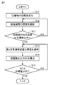
- 4 is a flow chart for explaining control of a control device in a first operation mode (Embodiment 1).
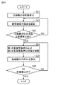
- FIG. 4 is a flowchart for explaining control of a control device in a second operation mode (Embodiment 1).
- FIG. 4 is a refrigerant circuit diagram showing the configuration of a refrigeration cycle device (Embodiment 2).
- FIG. 11 is a refrigerant circuit diagram showing the configuration of a refrigeration cycle device (Embodiment 3).
- 9 is a flowchart for explaining control of the control device in the second operation mode (Embodiment 3).
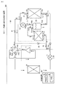
- FIG. 1 is a refrigerant circuit diagram showing the configuration of a refrigeration cycle device 100 according to Embodiment 1.
- the refrigeration cycle device 100 includes a compressor 1, an expansion device 3, a four-way valve 4, a gas-liquid separator 6, a first heat exchanger 10, a second heat exchanger 20, a third heat exchanger 30, and a first flow control device. 51 and a refrigerant circuit including at least a control device 90 .
- the first heat exchanger 10 is mounted on the indoor unit.
- the second heat exchanger 20 and the third heat exchanger 30 are mounted on the outdoor unit.
- a gas-liquid separator 6 is arranged between the second heat exchanger 20 and the third heat exchanger 30 .
- This configuration is equivalent to a configuration in which the heat exchanger on the outdoor unit side is divided into two heat exchangers and the gas-liquid separator 6 is arranged between one heat exchanger and the other heat exchanger.
- the second heat exchanger 20 has a first port P1 and a second port P2.
- the third heat exchanger 30 has a third port P3 and a fourth port P4.
- the gas-liquid separator 6 includes an inflow port P61, a gas discharge port P62, and a liquid discharge port P63. Between the gas discharge port P62 and the third heat exchanger 30, a first flow rate adjusting device 51 that adjusts the flow rate of refrigerant is provided.
- the first flow rate adjusting device 51 includes a valve for adjusting the flow rate of the refrigerant.
- the first flow control device 51 changes the flow rate of the refrigerant by adjusting the opening degree of the valve.
- the gas discharge port P62 is connected to the third port P3 of the third heat exchanger 30 via the first flow control device 51.
- the gas discharge port P62 discharges gaseous refrigerant from the gas-liquid separator 6 .
- the liquid discharge port P63 is connected to the fourth port P4 of the third heat exchanger 30 .
- the liquid discharge port P63 discharges liquid refrigerant from the gas-liquid separator 6 .
- the refrigerant in gas state will be referred to as gas refrigerant
- the refrigerant in liquid state will be referred to as liquid refrigerant.
- refrigerant is simply used.
- the four-way valve 4 has a first switching port P41, a second switching port P42, a third switching port P43, and a fourth switching port P44.
- a discharge port of the compressor 1 is connected to the first switching port P41, and a suction port of the compressor 1 is connected to the second switching port P42.
- a first check valve 41 , a second check valve 42 , a third check valve 43 and a fourth check valve 44 are provided in the refrigerant circuit of the refrigeration cycle device 100 .
- the first check valve 41 is provided between the fourth switching port P44 of the four-way valve 4 and the point a shown in FIG. 1 on the refrigerant circuit.
- a point a corresponds to a first confluence point where the refrigerant discharged from the third port P3 of the third heat exchanger 30 and the refrigerant discharged from the first flow control device 51 join.
- the first check valve 41 blocks the flow of refrigerant from the fourth switching port P44 toward the first junction a.
- the second check valve 42 is provided between the fourth switching port P44 of the four-way valve 4 and the first port P1 of the second heat exchanger 20.
- the second check valve 42 blocks the flow of refrigerant from the expansion device 3 toward the fourth switching port P44 of the four-way valve 4 .
- the third check valve 43 is provided between the fourth switching port P44, the expansion device 3, and the first port P1 of the second heat exchanger 20.
- the third check valve 43 blocks the flow of refrigerant from the fourth switching port to the expansion device 3 .
- the fourth check valve 44 is provided between the expansion device 3 and the point b shown in FIG. 1 on the refrigerant circuit.
- a point b corresponds to a second confluence point where the refrigerant discharged from the fourth port P4 of the third heat exchanger 30 and the refrigerant discharged from the liquid discharge port P63 of the gas-liquid separator 6 join.
- the fourth check valve 44 blocks the flow of refrigerant from the expansion device 3 to the second junction b.
- the four-way valve 4 changes between the first state and the second state.
- the first switching port P41 communicates with the third switching port P43
- the second switching port P42 communicates with the fourth switching port P44.
- the first switching port P41 communicates with the fourth switching port P44
- the second switching port P42 communicates with the third switching port P43.
- the four-way valve 4 switches the direction in which the refrigerant discharged from the compressor 1 flows through the flow path by changing between the first state and the second state.
- the four-way valve 4, the first check valve 41, the second check valve 42, the third check valve 43, and the fourth check valve 44 function so that the refrigerant circulates in the first order and the second order. Switch to the order. As a result, the operation mode of the refrigeration cycle device 100 is switched between the first operation mode and the second operation mode.
- the first operation mode high pressure refrigerant flows into the first heat exchanger 10 .
- the second operation mode low pressure refrigerant flows into the first heat exchanger 10 .
- the first operation mode corresponds to heating operation
- the second operation mode corresponds to cooling operation.
- the control device 90 sets the four-way valve 4 to the first state in the first operation mode, and sets the four-way valve 4 to the second state in the second operation mode.
- the four-way valve 4, the first check valve 41, the second check valve 42, the third check valve 43, and the fourth check valve 44 constitute a switching device 40 for switching the operation mode.
- the switching device 40 switches the route in which the refrigerant discharged from the compressor 1 circulates between a first route corresponding to the first operation mode and a second route corresponding to the second operation mode.
- a plurality of temperature sensors including a first temperature sensor 71 , a second temperature sensor 72 and a third temperature sensor 73 are provided in the refrigerant circuit of the refrigeration cycle device 100 .
- the first temperature sensor 71 is provided on the side of the gas-liquid separator 6 from which gaseous refrigerant is discharged. More specifically, the first temperature sensor 71 is provided between the side of the gas-liquid separator 6 from which gaseous refrigerant is discharged and the first flow rate adjusting device 51 .
- the second temperature sensor 72 is provided on the third port P3 side of the third heat exchanger 30 . More specifically, the second temperature sensor 72 is provided between the third port P3 side of the third heat exchanger 30 and the first junction a.
- the third temperature sensor 73 is provided on the fourth port P4 side of the third heat exchanger 30 . More specifically, the third temperature sensor 73 is provided between the fourth port P4 side of the third heat exchanger 30 and the second junction b.
- the control device 90 includes a processor 91 and a memory 92 .
- the memory 92 includes ROM (Read Only Memory) and RAM (Random Access Memory).
- the processor 91 expands a program stored in ROM into RAM or the like and executes it.
- the program stored in the ROM is a program in which processing procedures of the control device 90 are described.
- the control device 90 controls each device in the refrigeration cycle device 100 according to a program stored in the memory 92 .
- the control device 90 controls the compressor 1 , the expansion device 3 , the four-way valve 4 and the first flow control device 51 .
- the second heat exchanger 20 is located upstream of the refrigerant. is located, and the third heat exchanger 30 is located downstream of the refrigerant.
- a non-azeotropic mixed refrigerant such as R466A will be described as an example of the refrigerant.
- a non-azeotropic refrigerant mixture is formed by mixing two or more refrigerants with different boiling points. For this reason, the non-azeotropic mixed refrigerant has the characteristic that a deviation occurs between the saturated gas temperature and the saturated liquid temperature under a constant pressure. Generally, the saturated gas temperature is higher than the saturated liquid temperature. Such temperature differences are called temperature gradients.
- the present disclosure proposes a configuration that can improve driving performance while reducing pressure loss when a non-azeotropic refrigerant mixture is used.
- the present disclosure proposes a configuration applicable to both the first operating mode and the second operating mode.
- the heat exchanger in the outdoor unit is divided into a second heat exchanger 20 on the upstream side and a third heat exchanger 30 on the downstream side.
- a gas-liquid separator 6 is arranged in the flow path on the way to the heat exchanger 30 .
- the operating capability is improved by flowing liquid refrigerant or gas refrigerant to the third heat exchanger 30 on the downstream side according to the operation mode.
- the refrigerant applicable to the refrigeration cycle device 100 is not limited to the non-azeotropic mixed refrigerant.
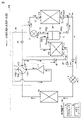
- FIG. 2 is a diagram showing the flow of refrigerant in the first operation mode of refrigeration cycle apparatus 100. As shown in FIG. The refrigerant flow in the first operation mode will be described with reference to FIG. In the first operation mode, the control device 90 controls the four-way valve 4 so that the flow path indicated by the solid line in FIG. 2 is formed in the four-way valve 4 .
- the switching device 40 including the four-way valve 4 works to cause the refrigerant to flow through the refrigerant circuit of the refrigeration cycle device 100 as indicated by the arrow. That is, the refrigerant discharged from the compressor 1 passes through the first switching port P41 and the third switching port P43 of the four-way valve 4, the first heat exchanger 10, the expansion device 3, the second heat exchanger 20, the gas-liquid It flows through the separator 6 in order. After that, the liquid refrigerant discharged from the liquid discharge port P63 of the gas-liquid separator 6 flows into the third heat exchanger 30 from the fourth port P4.
- the gas refrigerant discharged from the gas discharge port P62 of the gas-liquid separator 6 passes through the first flow rate adjusting device 51 toward the first junction a shown in FIG.
- the refrigerant discharged from the third port P3 of the third heat exchanger 30 also flows into the first junction a.
- the refrigerant merged from two directions at the first confluence point a flows into the suction port of the compressor 1 via the four-way valve 4 .
- the first route of the refrigerant in the first operation mode is configured by the route of the refrigerant outlined above. That is, in the first route, the refrigerant flows through the compressor 1, the first heat exchanger 10, the expansion device 3, the second heat exchanger 20, and the gas-liquid separator 6 in this order, and then is discharged from the gas-liquid separator 6. While the liquid state refrigerant discharged from the gas-liquid separator 6 flows into the third heat exchanger 30, the gas state refrigerant discharged from the gas-liquid separator 6 flows from the third heat exchanger 30 via the first flow rate adjusting device 51 It merges with the discharged refrigerant at the first confluence point a. The refrigerant merged at the first junction a flows into the compressor 1 .
- the refrigerant flow in the first operation mode will be described in more detail.
- the first heat exchanger 10 on the indoor unit side functions as a condenser
- the second heat exchanger 20 and the third heat exchanger 30 on the outdoor unit side function as evaporators.
- the high-temperature, high-pressure gas refrigerant discharged from the compressor 1 flows into the first heat exchanger 10 on the indoor unit side after passing through the four-way valve 4 .
- the gas refrigerant that has flowed into the first heat exchanger 10 is condensed by radiating heat to the indoor air. As a result, liquefaction of the refrigerant progresses in the first heat exchanger 10 .
- the refrigerant discharged from the first heat exchanger 10 flows into the expansion device 3 .
- the expansion device 3 has a valve for adjusting the degree of expansion of the refrigerant.
- the refrigerant discharged from the first heat exchanger 10 expands in the expansion device 3 to change into a two-phase refrigerant in which gas and liquid are mixed.
- the two-phase refrigerant discharged from the expansion device 3 passes through the third check valve 43 and flows from the first port P1 into the second heat exchanger 20 on the outdoor unit side.
- a fourth check valve 44 blocks the flow of refrigerant from the expansion device 3 toward the second junction b.
- the two-phase refrigerant with a higher degree of dryness is discharged from the second port P2 of the second heat exchanger 20.
- the two-phase refrigerant discharged from the second port P2 flows into the gas-liquid separator 6 from the inflow port P61 and is separated into gas refrigerant and liquid refrigerant.
- the liquid refrigerant separated by the gas-liquid separator 6 is discharged from the liquid discharge port P63.
- the liquid refrigerant discharged from the liquid discharge port P63 flows into the third heat exchanger 30 from the fourth port P4. At this time, the liquid refrigerant discharged from the liquid discharge port P63 does not flow through the fourth check valve 44 to the expansion device 3 side. This is because the pressure of the liquid refrigerant discharged from the liquid discharge port P63 is lower than the pressure of the refrigerant flowing from the expansion device 3 toward the third check valve 43.
- the pressure difference corresponds to the pressure loss between the second heat exchanger 20 portion and the third check valve 43 portion.
- the third temperature sensor 73 detects the temperature of the liquid refrigerant flowing into the third heat exchanger 30 from the fourth port P4. The temperature detected by the third temperature sensor 73 is transmitted to the control device 90 .
- the gas refrigerant separated by the gas-liquid separator 6 is discharged from the gas discharge port P62.
- the gas refrigerant discharged from the gas discharge port P ⁇ b>62 passes through the first flow control device 51 toward the first junction a on the downstream side of the third heat exchanger 30 without flowing into the third heat exchanger 30 . Therefore, of the second heat exchanger 20 and the third heat exchanger 30 in the outdoor unit, the liquid refrigerant flows into the downstream third heat exchanger 30, and the gas refrigerant does not flow.
- the first temperature sensor 71 detects the temperature of the gas refrigerant separated by the gas-liquid separator 6 .
- the temperature detected by the first temperature sensor 71 is transmitted to the control device 90 .
- This temperature is equivalent to the saturated gas temperature of the refrigerant flowing into the gas-liquid separator 6 .
- the control device 90 estimates the pressure inside the gas-liquid separator 6 from the temperature detected by the first temperature sensor 71 .
- the liquid refrigerant exchanges heat with the outside air and gasifies.
- gas refrigerant does not flow into the third heat exchanger 30 , no temperature gradient occurs in the third heat exchanger 30 .
- the temperature in the third heat exchanger 30 is not uneven.
- the gasified refrigerant in the third heat exchanger 30 is discharged from the third port P3.
- the second temperature sensor 72 detects the temperature of the gas refrigerant discharged from the third port P3.
- the temperature detected by the second temperature sensor 72 is transmitted to the control device 90 .
- the temperature detected by the second temperature sensor 72 corresponds to the outlet temperature of the evaporator in the first operating mode.
- the control device 90 estimates the degree of superheat (SH: Super Heat) at the evaporator outlet based on the temperature detected by the first temperature sensor 71 and the temperature detected by the second temperature sensor 72 .
- the gas refrigerant discharged from the third port P3 of the third heat exchanger 30 joins with the gas refrigerant discharged from the first flow control device 51 at the first confluence point a.
- the gas refrigerant merged from two directions flows into the suction side of the compressor 1 through the first check valve 41 and the four-way valve 4 .
- the gas refrigerant does not flow to the second heat exchanger 20 through the second check valve 42 .
- the pressure difference corresponds to the pressure loss between the second heat exchanger 20 and the first check valve 41 .
- FIG. 3 is a diagram showing the flow of refrigerant in the second operation mode of refrigeration cycle apparatus 100. As shown in FIG. The refrigerant flow in the second operation mode will be described with reference to FIG. In the second operation mode, the control device 90 controls the four-way valve 4 so that the flow path indicated by the solid line in FIG. 3 is formed in the four-way valve 4 .
- the switching device 40 including the four-way valve 4 works to cause the refrigerant to flow through the refrigerant circuit of the refrigeration cycle device 100 as indicated by the arrow. That is, the refrigerant discharged from the compressor 1 passes through the first switching port P41 and the fourth switching port P44 of the four-way valve 4 and flows through the second heat exchanger 20 and the gas-liquid separator 6 in this order. After that, the gas refrigerant discharged from the gas discharge port P62 of the gas-liquid separator 6 flows into the third heat exchanger 30 from the third port P3 via the first flow control device 51 .
- the liquid refrigerant discharged from the liquid discharge port P63 of the gas-liquid separator 6 joins the refrigerant discharged from the fourth port P4 of the third heat exchanger 30 at the second junction b.
- the refrigerant merged at the second junction b flows through the expansion device 3 and the first heat exchanger 10 in this order, and then flows through the four-way valve 4 to the suction port of the compressor 1 .
- the refrigerant route outlined above constitutes the second refrigerant route in the second operation mode. That is, in the second route, the refrigerant flows through the compressor 1, the second heat exchanger 20, and the gas-liquid separator 6 in this order, and then the gaseous refrigerant discharged from the gas-liquid separator 6 is adjusted to the first flow rate. While flowing into the third heat exchanger 30 via the device 51, the liquid state refrigerant discharged from the gas-liquid separator 6 joins the refrigerant discharged from the third heat exchanger 30 at the second junction b After joining, the refrigerant joined at the second joining point b flows through the expansion device 3, the first heat exchanger 10, and the compressor 1 in this order.
- the indoor unit side first heat exchanger 10 functions as an evaporator
- the outdoor unit side second heat exchanger 20 and third heat exchanger 30 function as condensers.
- the high-temperature, high-pressure gas refrigerant discharged from the compressor 1 flows from the first port P1 through the second check valve 42 into the second heat exchanger 20 on the outdoor unit side. do.
- a first check valve 41 blocks the flow of refrigerant from the four-way valve 4 toward the first confluence point a.
- the gas refrigerant that has flowed into the second heat exchanger 20 is condensed by radiating heat to the outside air, and changes into a two-phase refrigerant in which gas and liquid are mixed.
- the two-phase refrigerant discharged from the second port of the second heat exchanger 20 flows into the gas-liquid separator 6 from the inflow port P61 and is separated into gas refrigerant and liquid refrigerant.
- the gas refrigerant separated by the gas-liquid separator 6 is discharged from the gas discharge port P62.
- the gas refrigerant discharged from the gas discharge port P62 flows into the third heat exchanger 30 from the third port P3 through the first flow regulating device 51 .
- the gas refrigerant discharged from the first flow control device 51 does not flow through the first check valve 41 to the fourth switching port P44 side of the four-way valve 4 .
- the reason for this is that the pressure of the gaseous refrigerant discharged from the first flow rate adjusting device 51 is lower than the pressure of the refrigerant at the fourth switching port P44 of the four-way valve 4 .
- the pressure difference corresponds to the pressure loss between the four-way valve 4 and the first check valve 41 .
- the liquid refrigerant separated by the gas-liquid separator 6 is discharged from the liquid discharge port P63.
- the liquid refrigerant discharged from the liquid discharge port P ⁇ b>63 goes downstream of the third heat exchanger 30 without flowing into the third heat exchanger 30 . Therefore, of the second heat exchanger 20 and the third heat exchanger 30 in the outdoor unit, the gas refrigerant flows into the downstream third heat exchanger 30, and the liquid refrigerant does not flow.
- the gas refrigerant exchanges heat with the outside air and condenses. As a result, liquefaction of the refrigerant progresses in the third heat exchanger 30 . As described above, no liquid refrigerant flows into the third heat exchanger 30 , so no temperature gradient occurs in the third heat exchanger 30 . As a result, the temperature in the third heat exchanger 30 is not uneven.
- the liquid refrigerant discharged from the fourth port P4 of the third heat exchanger 30 joins the liquid refrigerant discharged from the liquid discharge port P63 of the gas-liquid separator 6 at the second junction b.
- the liquid refrigerant merged at the second junction b flows into the expansion device 3 through the fourth check valve 44 .
- liquid refrigerant does not flow to the second heat exchanger 20 through the third check valve 43 .
- the refrigerant pressure at the fourth check valve 44 portion is lower than the refrigerant pressure at the first port P1 portion of the second heat exchanger 20 .
- the pressure difference corresponds to the pressure loss of the second heat exchanger 20 , the first flow regulating device 51 and the fourth check valve 44 .
- the refrigerant that has flowed into the expansion device 3 is expanded by the expansion device 3, and then flows into the first heat exchanger 10 on the indoor unit side.
- the refrigerant that has flowed into the first heat exchanger 10 absorbs heat from the indoor air and evaporates, and then flows into the suction side of the compressor 1 through the four-way valve 4 .
- the first check valve 41 and the second check valve 42 constitute a first valve mechanism.
- a second valve mechanism is configured by the third check valve 43 and the fourth check valve 44 .
- the first valve mechanism communicates the expansion device 3 with the first port P1 of the second heat exchanger 20 in the first operation mode in which the four-way valve 4 is in the first state, and the expansion device 3 communicates with the third heat exchanger. Communication with the fourth port P4 of the exchanger 30 is cut off.
- the first valve mechanism opens the flow of refrigerant from the first junction a to the fourth switching port P44 and blocks the flow of refrigerant from the expansion device 3 to the fourth switching port P44. Furthermore, in the second operation mode, the first valve mechanism opens the flow of refrigerant from the fourth switching port P44 to the second heat exchanger 20, and allows the flow of refrigerant from the fourth switching port P44 to the first junction a. block the
- the second valve mechanism opens the flow of refrigerant from the expansion device 3 to the second heat exchanger 20, blocks the flow of refrigerant from the expansion device 3 to the second junction b, and In the second operation mode, the refrigerant flow from the second junction b to the expansion device 3 is opened, and the refrigerant flow from the fourth switching port P44 to the expansion device 3 is blocked.
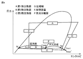
- FIG. 4 is a ph diagram showing changes in refrigerant state in the first operation mode.
- FIG. 4 will be described with reference to FIG.
- hout, hout', hg, hl, hin, and hsep shown in FIG. 4 respectively correspond to Pout, Poout', Pog, Pol, Poin, and Posep in FIG.
- the enthalpy at Poin in the refrigerant circuit of FIG. 2 corresponds to hin shown in FIG.
- the high-temperature, high-pressure gas refrigerant discharged from the compressor 1 is condensed by the first heat exchanger 10 .
- the refrigerant is two-phased into a gas refrigerant and a liquid refrigerant in the expansion device 3 and then flows into the second heat exchanger 20 .
- the enthalpy of the refrigerant at this time is hin.
- Two-phase refrigerant with a higher dryness is discharged from the second heat exchanger 20 .
- the discharged two-phase refrigerant flows into the gas-liquid separator 6 .
- the enthalpy of the refrigerant at this time is hsep.
- the two-phase refrigerant that has flowed into the gas-liquid separator 6 is separated into gas refrigerant and liquid refrigerant in the gas-liquid separator 6 .
- the gas refrigerant discharged from the gas-liquid separator 6 goes to the first flow control device 51 .
- the enthalpy of the gas refrigerant at this time is hg.
- the gas refrigerant discharged from the gas-liquid separator 6 goes to the third heat exchanger 30 .
- the enthalpy of the liquid refrigerant at this time is hl.
- the amount of refrigerant flowing into the gas-liquid separator 6 is X [kg/hr]
- the amount of gas refrigerant discharged from the gas-liquid separator 6 is Y [kg/hr]
- the evaporation capacity is represented by the following formula (1).
- the flow rate X is determined by the rotation speed of the compressor 1, the suction density of the compressor 1, and the like.
- the flow rate Y and the flow rate Z are determined by the degree of opening of the first flow control device 51 attached to the gas refrigerant outlet side of the gas-liquid separator 6 .
- the enthalpy hsep of the refrigerant flowing into the gas-liquid separator 6 can be adjusted by adjusting the size of the second heat exchanger 20 functioning as an evaporator, the air volume, and the like. Therefore, by adjusting the degree of opening of the first flow rate adjusting device 51 while considering the composition change of the refrigerant, the evaporation capacity can be improved.
- the liquid refrigerant that has flowed into the third heat exchanger 30 exchanges heat with the outside air and is gasified. As a result, the enthalpy of the refrigerant discharged from the third heat exchanger 30 becomes hout'.
- the gas refrigerant discharged from the third heat exchanger 30 joins with the gas refrigerant discharged from the first flow control device 51 at the confluence point a. The enthalpy of the gas refrigerant at this time is hout. After that, the gas refrigerant returns to the compressor 1 through the four-way valve 4 .
- pressure loss can be reduced compared to the case where the entire amount of the two-phase refrigerant flows through the third heat exchanger 30 .
- the dryness at the inlet of the third heat exchanger 30 becomes almost zero. Therefore, the flow velocity of the refrigerant flowing through the third heat exchanger 30 can be lowered compared to the case where the two-phase refrigerant flows. As a result, pressure loss can be improved also from the viewpoint of flow velocity.
- the present embodiment only the liquid refrigerant with almost zero dryness is allowed to flow to the third heat exchanger 30 .
- Such a liquid refrigerant is less susceptible to gravity and flow bias. Therefore, by allowing only the liquid refrigerant to flow through the third heat exchanger 30, the flow rate of the refrigerant in each flow path can be made uniform. As a result, according to the present embodiment, it is possible to improve the unevenness of the coolant temperature due to the temperature gradient.
- the amount of liquid refrigerant flowing through the third heat exchanger 30 can be controlled by adjusting the degree of opening of the first flow rate adjusting device 51 .
- the degree of opening of the first flow rate adjusting device 51 For example, when the rotation speed of the compressor 1 and the opening degree of the expansion device 3 are constant and the opening degree of the first flow rate adjusting device 51 is increased, bypass to the outlet side of the third heat exchanger 30 functioning as an evaporator.
- the amount of gas refrigerant flowing through the third heat exchanger 30 increases, and the amount of liquid refrigerant flowing through the third heat exchanger 30 decreases.
- the degree of superheat at the outlet of the third heat exchanger 30 increases.
- the degree of opening of the first flow rate adjusting device 51 is reduced, the amount of liquid refrigerant flowing into the third heat exchanger 30 increases, so the liquid refrigerant does not completely gasify inside the third heat exchanger 30 .
- the degree of superheat is reduced. Therefore, the degree of superheat at the outlet of the third heat exchanger 30 can be controlled to an optimum value by adjusting the degree of opening of the first flow rate adjusting device 51 and increasing or decreasing the amount of bypass gas refrigerant. can.
- the degree of superheat at the outlet of the third heat exchanger 30 can be estimated based on the temperature detected by the first temperature sensor 71 and the temperature detected by the second temperature sensor 72 . Since the non-azeotropic refrigerant mixture has a temperature gradient, it is difficult to estimate the saturation temperature from the temperature of the refrigerant in the two-phase state. It can accurately estimate the degree of superheat.
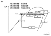
- FIG. 5 is a ph diagram showing changes in refrigerant state in the second operation mode.
- FIG. 5 will be described with reference to FIG.
- hout, hout', hg, hl, hin, and hsep in FIG. 5 correspond to Pout, Poout', Pog, Pol, Poin, and Posep in FIG. 3, respectively.
- the high-temperature, high-pressure gas refrigerant discharged from the compressor 1 flows into the second heat exchanger 20 .
- the enthalpy of the refrigerant at this time is hin.
- the refrigerant that has flowed into the second heat exchanger 20 is condensed and discharged as a two-phase refrigerant.
- the two-phase refrigerant discharged from the second heat exchanger 20 flows into the gas-liquid separator 6 .
- the enthalpy of the refrigerant at this time is hsep.
- the two-phase refrigerant that has flowed into the gas-liquid separator 6 is separated into gas refrigerant and liquid refrigerant in the gas-liquid separator 6 .
- the gas refrigerant discharged from the gas-liquid separator 6 goes to the third heat exchanger 30 through the first flow control device 51 .
- the enthalpy of the gas refrigerant before the first flow control device 51 is hg.
- the liquid refrigerant discharged from the gas-liquid separator 6 goes downstream of the third heat exchanger 30 .
- the enthalpy of the liquid refrigerant at this time is hl.
- the amount of refrigerant flowing into the gas-liquid separator 6 is X [kg/hr]
- the amount of gas refrigerant discharged from the gas-liquid separator 6 is Y [kg/hr]
- the condensation capacity is represented by the following formula (2).
- the gas refrigerant that has flowed into the third heat exchanger 30 exchanges heat with the outside air and condenses. As a result, the enthalpy of the refrigerant discharged from the third heat exchanger 30 becomes hout'.
- the refrigerant discharged from the third heat exchanger 30 joins the liquid refrigerant discharged from the gas-liquid separator 6 at the second junction b.
- the enthalpy of the refrigerant at this time is hout.
- the refrigerant is expanded by the expansion device 3 , flows into the first heat exchanger 10 , evaporates, and then returns to the compressor 1 through the four-way valve 4 .
- the second operation mode when the non-azeotropic refrigerant mixture flows into the second heat exchanger 20 on the outdoor unit side, the refrigerant with a high boiling point is preferentially condensed in the second heat exchanger 20 rather than the refrigerant with a low boiling point. be. Therefore, most of the gas refrigerant in the gas-liquid separator 6 is low boiling point refrigerant, and most of the liquid refrigerant in the gas/liquid separator 6 is high boiling point refrigerant. In the second operation mode, only the gaseous refrigerant separated by the gas-liquid separator 6 flows to the third heat exchanger 30, so that the refrigerant with a low boiling point component is condensed in the third heat exchanger 30.
- the gas-liquid separator 6, of the second heat exchanger 20 and the third heat exchanger 30 by using the gas-liquid separator 6, of the second heat exchanger 20 and the third heat exchanger 30, the low boiling point component is transferred to the third heat exchanger 30 on the downstream side.
- a large amount of refrigerant can flow.
- the efficiency of the refrigeration cycle can be improved.
- the amount of refrigerant flowing to the third heat exchanger 30 is adjusted by adjusting the opening degree of the first flow rate adjusting device 51 while considering the composition change of the refrigerant. can be adjusted. For example, if the opening of the first flow control device 51 is increased while the rotation speed of the compressor 1 and the opening of the expansion device 3 are kept constant, the amount of gaseous refrigerant flowing to the third heat exchanger 30 increases. .
- the degree of supercooling (SC: Supercool) at the outlet of the third heat exchanger 30 is lowered.
- SC Supercool
- the degree of opening of the first flow rate adjusting device 51 is decreased, the degree of supercooling increases. Therefore, by adjusting the opening degree of the first flow rate adjusting device 51 and increasing or decreasing the amount of gaseous refrigerant flowing to the third heat exchanger 30, the degree of subcooling at the outlet portion of the third heat exchanger 30 is optimized. can be controlled to be
- the degree of subcooling at the outlet of the third heat exchanger 30 can be estimated based on the temperature detected by the first temperature sensor 71 and the temperature detected by the third temperature sensor 73 .
- FIG. 6 is a flow chart for explaining the control of the control device 90 in the first operation mode.
- the control device 90 changes the rotation speed of the compressor 1 (step S1).
- the rotation speed of the compressor 1 is determined by the difference between the temperature set by the remote controller of the indoor unit and the room temperature.
- the controller 90 changes the rotation speed of the compressor 1 to an appropriate value.
- control device 90 adjusts the opening degree of the expansion device 3 (step S2).
- control device 90 calculates the degree of supercooling (SC: Super cool) at the outlet of the first heat exchanger 10 that functions as a condenser (step S3).
- the degree of supercooling at the outlet of the first heat exchanger 10 can be calculated, for example, from the temperature at the outlet of the first heat exchanger 10 and the pressure of the first heat exchanger 10 . Therefore, a sensor for detecting temperature and a sensor for detecting pressure should be appropriately arranged in the refrigerant circuit.
- control device 90 determines whether or not the degree of subcooling at the outlet of the first heat exchanger 10 functioning as a condenser is within the target range (step S4).
- the opening degree of the expansion device 3 is adjusted again.
- the control device 90 keeps the expansion device 3 open degree repeatedly adjust.
- the target value area is the target value ⁇ target error.
- control device 90 determines in step S4 that the degree of subcooling at the outlet of the first heat exchanger 10 is within the target region, it adjusts the opening degree of the first flow rate adjusting device 51 (step S5).
- control device 90 calculates the degree of superheat (SH: Superheat) at the outlet of the third heat exchanger 30 that functions as an evaporator (step S6). At this time, the controller 90 calculates the degree of superheat at the outlet of the third heat exchanger 30 based on the temperature detected by the first temperature sensor 71 and the temperature detected by the second temperature sensor 72 .
- control device 90 determines whether or not the degree of superheat at the outlet of the third heat exchanger 30 functioning as an evaporator is within the target range (step S7).
- the control device 90 determines that the degree of superheat at the outlet of the third heat exchanger 30 is not within the target value, in step S5, the opening degree of the first flow rate adjusting device 51 is adjusted again.
- control device 90 keeps the first flow control device 51 in step S5 until the degree of superheat at the outlet of the third heat exchanger 30 is within the target region set for each rotation speed of the compressor 1. Repeatedly adjust the opening.
- the controller 90 determines that the degree of superheat at the outlet of the third heat exchanger 30 is within the target range, the process ends.
- the control device 90 closes the flow path by setting the opening degree of the first flow rate adjusting device 51 to zero, and the gas refrigerant is subjected to the third heat exchange. You may make it flow to the vessel 30. In this case, the control device 90 checks whether the rotation speed of the compressor 1 is within a specified rotation speed range each time the rotation speed of the compressor 1 changes.
- control device 90 performs the third heat exchange based on the detection value of the first temperature sensor 71 and the detection value of the second temperature sensor 72 in the first operation mode.
- the degree of superheat of the third heat exchanger 30 is controlled by calculating the degree of superheat of the heat exchanger 30 and adjusting the degree of opening of the first flow control device 51 .
- FIG. 7 is a flow chart for explaining the control of the control device 90 in the second operation mode.
- the control device 90 changes the rotation speed of the compressor 1 (step S11) as in the process of step S1.
- the control device 90 adjusts the opening degree of the expansion device 3 so that the discharge temperature of the compressor 1 is within the target range (step S12).
- the discharge temperature of the compressor 1 can be specified, for example, based on the detected value of a temperature sensor provided in the discharge portion of the compressor 1 .
- the control device 90 determines whether or not the discharge temperature of the compressor 1 is within the target range (step S13). When the control device 90 determines that the discharge temperature of the compressor 1 is not within the target range, the opening degree of the expansion device 3 is adjusted again in step S12.
- control device 90 determines in step S13 that the discharge temperature of the compressor 1 is within the target range, it adjusts the opening degree of the first flow rate adjusting device 51 (step S14).
- control device 90 calculates the degree of supercooling at the outlet of the third heat exchanger 30 that functions as a condenser (step S15). At this time, the controller 90 calculates the degree of subcooling at the outlet of the third heat exchanger 30 based on the temperature detected by the first temperature sensor 71 and the temperature detected by the third temperature sensor 73 .
- control device 90 determines whether or not the degree of subcooling at the outlet of the third heat exchanger 30 functioning as a condenser is within a target range set for each rotation speed of the compressor 1 (step S16).
- the opening degree of the first flow control device 51 is adjusted again.
- control device 90 keeps the first flow rate adjusting device 51 Repeatedly adjust the opening of the When the controller 90 determines that the degree of subcooling at the outlet of the third heat exchanger 30 is within the target range, the process ends.
- control device 90 performs the third heat exchange based on the detection value of the first temperature sensor 71 and the detection value of the third temperature sensor 73 in the second operation mode.
- the degree of supercooling of the third heat exchanger 30 is controlled by calculating the degree of supercooling of the heat exchanger 30 and adjusting the degree of opening of the first flow control device 51 .
- the refrigeration cycle apparatus 100 improves the operating capacity by flowing liquid refrigerant or gas refrigerant to the third heat exchanger 30 on the downstream side according to the operation mode. Therefore, according to the refrigerating cycle apparatus 100, the operating efficiency of the refrigerating cycle can be improved in both the first operating mode and the second operating mode.
- the gas-liquid separator 6 is used regardless of whether the second heat exchanger 20 and the third heat exchanger 30 on the outdoor unit side function as an evaporator or a condenser. It can be used to improve operational efficiency. In particular, when a non-azeotropic mixed refrigerant is used, the effect of improving the operating efficiency of the refrigeration cycle can be enhanced.
- FIG. 8 is a refrigerant circuit diagram showing the configuration of a refrigeration cycle device 110 according to the second embodiment.
- a refrigerating cycle device 110 according to the second embodiment differs from the refrigerating cycle device 100 according to the first embodiment in the configuration of a switching device.
- a refrigeration cycle device 110 according to the second embodiment includes a switching device 400 configured with a first three-way valve 45 and a second three-way valve 46 .
- the first three-way valve 45 is provided between the fourth switching port P44, the second heat exchanger 20 and the first junction a.
- the first three-way valve 45 switches the connection destination to the fourth switching port P44 between the second heat exchanger 20 and the first confluence point a.
- the second three-way valve 46 is provided between the expansion device 3, the second heat exchanger 20 and the second junction b.
- the second three-way valve 46 switches the connection destination to the expansion device 3 between the second heat exchanger 20 and the second junction b.
- the control device 90 controls the four-way valve 4, the first three-way valve 45, and the second three-way valve 46 so that the flow path indicated by the solid line in FIG. 8 is formed in the first operation mode. Thereby, the refrigerant circulates in the refrigerant circuit in the same order as shown in FIG. In the second operation mode, the control device 90 controls the four-way valve 4 as shown in FIG. 3, and switches the connection state of the first three-way valve 45 and the second three-way valve 46 to the state shown by the dashed line in FIG. . Thereby, the refrigerant circulates in the refrigerant circuit in the same order as shown in FIG.
- the first three-way valve 45 has the same function as the first check valve 41 and the second check valve 42 of the refrigeration cycle device 100 according to the first embodiment.
- the second three-way valve 46 has the same function as the third check valve 43 and the fourth check valve 44 of the refrigeration cycle apparatus 100 according to the first embodiment. Therefore, in Embodiment 2, the first valve mechanism is composed of the first three-way valve 45 and the second valve mechanism is composed of the second three-way valve 46 .
- a first valve mechanism related to Embodiment 1 is composed of a first check valve 41 and a second check valve 42 .
- the first valve mechanism related to Embodiment 2 is composed of the first three-way valve 45 .
- a second valve mechanism related to Embodiment 1 is composed of a third check valve 43 and a fourth check valve 44 .
- the second valve mechanism related to Embodiment 2 is composed of the second three-way valve 46 . Therefore, according to the second embodiment, the number of parts can be reduced as compared with the first embodiment.
- FIG. 9 is a refrigerant circuit diagram showing the configuration of a refrigeration cycle device 120 according to Embodiment 3. As shown in FIG.
- the refrigerating cycle device 120 according to the third embodiment further includes a second flow rate adjusting device 52 and a fourth temperature sensor 74 compared to the refrigerating cycle device 100 according to the first embodiment.
- the second flow regulating device 52 is provided between the side of the gas-liquid separator 6 where the liquid state refrigerant is discharged and the second junction b.
- the fourth temperature sensor 74 is provided between the liquid refrigerant discharge side of the gas-liquid separator 6 and the second flow control device 52 .
- control device 90 can control the amount of gas refrigerant discharged from the gas-liquid separator 6 and the amount of liquid refrigerant. can be adjusted more finely.
- the detection target of the first temperature sensor 71 is the temperature of the gas refrigerant
- the temperature gradient of the non-azeotropic refrigerant mixture is taken into account.
- the fourth temperature sensor 74 can directly detect the saturation temperature of the liquid refrigerant. Therefore, the control device 90 can more accurately calculate the degree of supercooling based on the values detected by the third temperature sensor 73 and the values detected by the fourth temperature sensor 74 .
- FIG. 10 is a flow chart for explaining the control of the control device 90 in the second operation mode according to the third embodiment.
- the flowchart shown in FIG. 10 differs from the flowchart shown in FIG. 7 only in that step S24 is provided instead of step S14.
- Steps S21 to S23 of Fig. 10 are the same as steps S11 to S13 of Fig. 7, so the description thereof will not be repeated here.
- the control device 90 adjusts the opening degrees of the first flow rate adjusting device 51 and the second flow rate adjusting device 52 in step S24.
- the control device 90 calculates the degree of subcooling at the outlet of the third heat exchanger 30 that functions as a condenser (step S25). At this time, the control device 90 calculates the degree of supercooling of the outlet portion of the third heat exchanger 30 based on the temperature detected by the third temperature sensor 73 and the temperature detected by the fourth temperature sensor 74 . As a result, the control device 90 calculates the degree of supercooling at the outlet portion of the third heat exchanger 30 based on the temperature detected by the first temperature sensor 71 and the temperature detected by the third temperature sensor 73. As a result, the degree of supercooling can be calculated more accurately.
- control device 90 determines whether or not the degree of subcooling at the outlet of the third heat exchanger 30 functioning as a condenser is within a target range set for each rotation speed of the compressor 1 (step S26).
- the control device 90 determines that the degree of supercooling at the outlet of the third heat exchanger 30 is not within the target region, in step S24, the opening degrees of the first flow rate adjusting device 51 and the second flow rate adjusting device 52 to adjust.
- control device 90 keeps the first flow rate adjusting device 51 and the opening degree of the second flow control device 52 is repeatedly adjusted.
- the controller 90 determines that the degree of subcooling at the outlet of the third heat exchanger 30 is within the target range, the process ends.
- the first valve mechanism is composed of the first check valve 41 and the second check valve 42, and the second valve mechanism is composed of the third check valve 43 and the fourth check valve 44. is doing.
- the first valve mechanism may be composed of the first three-way valve 45 and the second valve mechanism may be composed of the second three-way valve 46 .
- a refrigeration cycle device (100) includes a compressor (1), a first heat exchanger (10), a second heat exchanger (20), a third heat exchanger (30), and an expansion device (3). , the gas-liquid separator (6), the first flow rate adjusting device (51), and the refrigerant circulation path between the first route corresponding to the first operation mode and the second route corresponding to the second operation mode. a switching device (40) configured to switch. In the first route, the refrigerant flows through the compressor (1), the first heat exchanger (10), the expansion device (3), the second heat exchanger (20), and the gas-liquid separator (6) in this order.
- the liquid state refrigerant discharged from the gas-liquid separator (6) flows into the third heat exchanger (30), and the gas state refrigerant discharged from the gas-liquid separator (6) flows into the first flow rate Via the adjusting device (51), it joins with the refrigerant discharged from the third heat exchanger (30) at the first junction (a).
- the refrigerant merged at the first junction (a) flows to the compressor (1).
- the refrigerant flows through the compressor (1), the second heat exchanger (20), and the gas-liquid separator (6) in this order, and the gaseous refrigerant discharged from the gas-liquid separator (6) is , flows through the first flow rate adjusting device (51) into the third heat exchanger (30), and the liquid state refrigerant discharged from the gas-liquid separator (6) flows into the third heat exchanger (30 ) joins with the refrigerant discharged from the second junction (b), and the refrigerant joined at the second junction (b) passes through the expansion device (3), the first heat exchanger (10), the compressor (1 ).
- the operating efficiency of the refrigeration cycle can be improved in both the first operation mode and the second operation mode.
- the heat exchanger functions as either an evaporator or a condenser
- the effect of improving the operating efficiency of the refrigeration cycle can be enhanced.
- the switching device (40) includes a four-way valve (4), first valve mechanisms (41, 42), and second valve mechanisms (43, 44).
- the four-way valve (4) has a first switching port (P41), a second switching port (P42), a third switching port (P43), and a fourth switching port (P44). is connected to the discharge port of the compressor (1), and the second switching port (P42) is connected to the suction port of the compressor (1).
- the four-way valve (4) communicates the first switching port (P41) and the third switching port (P43) and communicates the second switching port (P42) and the fourth switching port (P44) in the first operation mode.
- the first switching port (P41) and the fourth switching port (P44) are communicated, and the second switching port (P42) and the third switching port (P43) are communicated.
- the first valve mechanism (41, 42) opens the flow of refrigerant from the first junction (a) to the fourth switching port (P44) in the first operation mode, and the expansion device (3) to the fourth switching port (P44).
- the first valve mechanism (41, 42) is provided between the fourth switching port (P44) and the first junction (a), and the fourth switching port (P44) to the first junction (a) ), and is provided between the expansion device (3), the fourth switching port (P44), and the second heat exchanger (20).
- the second valve mechanism (43, 44) is provided between the fourth switching port (P44), the expansion device (3) and the second heat exchanger (20), and the expansion device is connected to the fourth switching port (P44).
- a third check valve (43) that cuts off the flow of refrigerant to (3) is provided between the expansion device and the second junction (b), and is provided between the expansion device (3) and the second junction (b). ) and a fourth check valve (44) for blocking the flow of refrigerant to (44).
- the first valve mechanism may be composed of a first three-way valve (45).
- the second valve mechanism may comprise a second three-way valve (46).
- the first three-way valve (45) is provided between the fourth switching port (P44), the second heat exchanger (20) and the first junction (a), and is connected to the fourth switching port (P44). Switching ahead between the second heat exchanger (20) and the first junction (a).
- a second three-way valve (46) is provided between the expansion device (3), the second heat exchanger (20) and the second junction (b), and connects the expansion device (3) to the second Switching between the heat exchanger (20) and the second junction (b).
- the refrigerating cycle device has a first temperature sensor (71) provided between the gas-liquid separator (6) where the gaseous refrigerant is discharged (P62) and the first flow rate adjusting device (51). , a second temperature sensor (72) provided between the third heat exchanger (30) and the first junction (a), and a control device (90) for controlling the first flow control device (51) further provide.
- the controller (90) determines the degree of superheat of the third heat exchanger (30) based on the detected value of the first temperature sensor (71) and the detected value of the second temperature sensor (72).
- the degree of superheat of the third heat exchanger (30) is controlled by calculating (step S6) and adjusting the degree of opening of the first flow control device (51) (steps S5 to S7).
- the refrigeration cycle device may further include a third temperature sensor (73) provided between the third heat exchanger (30) and the second junction (b).
- the controller (90) adjusts the degree of supercooling of the third heat exchanger (30) based on the detected value of the first temperature sensor (71) and the detected value of the third temperature sensor (73). is calculated (step S15), and the degree of supercooling of the third heat exchanger (30) is controlled by adjusting the opening degree of the first flow control device (51) (steps S14 to S16).
- the refrigeration cycle device includes a second flow rate adjusting device (52 ), the third temperature sensor (73) provided between the third heat exchanger (30) and the second junction (b), and the gas-liquid separator (6), the liquid refrigerant is discharged
- a fourth temperature sensor (74) provided between the side (P63) and the second flow control device (52) may further be provided.
- the controller (90) adjusts the degree of supercooling of the third heat exchanger (30) based on the values detected by the third temperature sensor (73) and the values detected by the fourth temperature sensor (74). is calculated (step S25), and the degree of supercooling of the third heat exchanger (30) is controlled by adjusting the opening degrees of the first flow rate adjusting device (51) and the second flow rate adjusting device (52) ( Steps S24 to S26).
Landscapes
- Engineering & Computer Science (AREA)
- Physics & Mathematics (AREA)
- Mechanical Engineering (AREA)
- Thermal Sciences (AREA)
- General Engineering & Computer Science (AREA)
- Compression-Type Refrigeration Machines With Reversible Cycles (AREA)
Abstract
Priority Applications (4)
| Application Number | Priority Date | Filing Date | Title |
|---|---|---|---|
| EP21932946.3A EP4317847A4 (fr) | 2021-03-24 | 2021-03-24 | Dispositif à cycle frigorifique |
| PCT/JP2021/012114 WO2022201336A1 (fr) | 2021-03-24 | 2021-03-24 | Dispositif à cycle frigorifique |
| JP2023508236A JPWO2022201336A1 (fr) | 2021-03-24 | 2021-03-24 | |
| CN202180095839.6A CN116981894A (zh) | 2021-03-24 | 2021-03-24 | 制冷循环装置 |
Applications Claiming Priority (1)
| Application Number | Priority Date | Filing Date | Title |
|---|---|---|---|
| PCT/JP2021/012114 WO2022201336A1 (fr) | 2021-03-24 | 2021-03-24 | Dispositif à cycle frigorifique |
Publications (1)
| Publication Number | Publication Date |
|---|---|
| WO2022201336A1 true WO2022201336A1 (fr) | 2022-09-29 |
Family
ID=83396449
Family Applications (1)
| Application Number | Title | Priority Date | Filing Date |
|---|---|---|---|
| PCT/JP2021/012114 WO2022201336A1 (fr) | 2021-03-24 | 2021-03-24 | Dispositif à cycle frigorifique |
Country Status (4)
| Country | Link |
|---|---|
| EP (1) | EP4317847A4 (fr) |
| JP (1) | JPWO2022201336A1 (fr) |
| CN (1) | CN116981894A (fr) |
| WO (1) | WO2022201336A1 (fr) |
Citations (4)
| Publication number | Priority date | Publication date | Assignee | Title |
|---|---|---|---|---|
| JPS6225644U (fr) | 1985-07-31 | 1987-02-17 | ||
| JP2005300067A (ja) * | 2004-04-14 | 2005-10-27 | Denso Corp | エジェクタサイクル |
| JP2019158308A (ja) * | 2018-03-16 | 2019-09-19 | 三菱電機株式会社 | 冷凍サイクル装置 |
| WO2021024443A1 (fr) * | 2019-08-07 | 2021-02-11 | 三菱電機株式会社 | Dispositif à cycle frigorifique |
Family Cites Families (1)
| Publication number | Priority date | Publication date | Assignee | Title |
|---|---|---|---|---|
| JP2003106685A (ja) * | 2001-09-28 | 2003-04-09 | Mitsubishi Electric Corp | 冷凍空調装置 |
-
2021
- 2021-03-24 JP JP2023508236A patent/JPWO2022201336A1/ja active Pending
- 2021-03-24 EP EP21932946.3A patent/EP4317847A4/fr active Pending
- 2021-03-24 WO PCT/JP2021/012114 patent/WO2022201336A1/fr active Application Filing
- 2021-03-24 CN CN202180095839.6A patent/CN116981894A/zh active Pending
Patent Citations (4)
| Publication number | Priority date | Publication date | Assignee | Title |
|---|---|---|---|---|
| JPS6225644U (fr) | 1985-07-31 | 1987-02-17 | ||
| JP2005300067A (ja) * | 2004-04-14 | 2005-10-27 | Denso Corp | エジェクタサイクル |
| JP2019158308A (ja) * | 2018-03-16 | 2019-09-19 | 三菱電機株式会社 | 冷凍サイクル装置 |
| WO2021024443A1 (fr) * | 2019-08-07 | 2021-02-11 | 三菱電機株式会社 | Dispositif à cycle frigorifique |
Non-Patent Citations (1)
| Title |
|---|
| See also references of EP4317847A4 |
Also Published As
| Publication number | Publication date |
|---|---|
| EP4317847A4 (fr) | 2024-05-01 |
| JPWO2022201336A1 (fr) | 2022-09-29 |
| CN116981894A (zh) | 2023-10-31 |
| EP4317847A1 (fr) | 2024-02-07 |
Similar Documents
| Publication | Publication Date | Title |
|---|---|---|
| US8047011B2 (en) | Refrigeration system | |
| AU660124B2 (en) | Air conditioning apparatus | |
| US9683768B2 (en) | Air-conditioning apparatus | |
| US11320170B2 (en) | Heat pump cycle | |
| KR100856991B1 (ko) | 냉동 공조장치, 냉동 공조장치의 운전 제어 방법, 냉동공조장치의 냉매량 제어 방법 | |
| US9958171B2 (en) | Air-conditioning apparatus | |
| KR100764339B1 (ko) | 과냉각 장치 | |
| EP2375188B1 (fr) | Climatiseur | |
| JP5213817B2 (ja) | 空気調和機 | |
| JP5355016B2 (ja) | 冷凍装置及び熱源機 | |
| JP2006284035A (ja) | 空気調和装置およびその制御方法 | |
| JPH11142010A (ja) | 冷凍空気調和装置 | |
| US20150075194A1 (en) | Air-conditioning apparatus | |
| JP6448780B2 (ja) | 空気調和装置 | |
| JP3140923B2 (ja) | 冷媒循環システムおよび冷凍・空調装置 | |
| WO2022201336A1 (fr) | Dispositif à cycle frigorifique | |
| JP2009293887A (ja) | 冷凍装置 | |
| JP2004020070A (ja) | ヒートポンプ式冷温水機 | |
| JP7294027B2 (ja) | 空気調和装置 | |
| JP7055239B2 (ja) | 空気調和装置 | |
| WO2017068649A1 (fr) | Système de pompe à chaleur | |
| JPH04214153A (ja) | 冷凍サイクル装置 | |
| JP2013217602A (ja) | 熱源機、冷凍空調装置、制御装置 | |
| WO2023223539A1 (fr) | Dispositif de climatisation | |
| JPH10306949A (ja) | 空気調和機 |
Legal Events
| Date | Code | Title | Description |
|---|---|---|---|
| 121 | Ep: the epo has been informed by wipo that ep was designated in this application |
Ref document number: 21932946 Country of ref document: EP Kind code of ref document: A1 |
|
| WWE | Wipo information: entry into national phase |
Ref document number: 2023508236 Country of ref document: JP |
|
| WWE | Wipo information: entry into national phase |
Ref document number: 202180095839.6 Country of ref document: CN |
|
| WWE | Wipo information: entry into national phase |
Ref document number: 2021932946 Country of ref document: EP |
|
| NENP | Non-entry into the national phase |
Ref country code: DE |
|
| ENP | Entry into the national phase |
Ref document number: 2021932946 Country of ref document: EP Effective date: 20231024 |