WO2023223539A1 - Dispositif de climatisation - Google Patents
Dispositif de climatisation Download PDFInfo
- Publication number
- WO2023223539A1 WO2023223539A1 PCT/JP2022/020941 JP2022020941W WO2023223539A1 WO 2023223539 A1 WO2023223539 A1 WO 2023223539A1 JP 2022020941 W JP2022020941 W JP 2022020941W WO 2023223539 A1 WO2023223539 A1 WO 2023223539A1
- Authority
- WO
- WIPO (PCT)
- Prior art keywords
- refrigerant
- gas
- valve
- pipe
- heat source
- Prior art date
Links
- 238000004378 air conditioning Methods 0.000 title abstract 2
- 239000003507 refrigerant Substances 0.000 claims abstract description 512
- 239000007788 liquid Substances 0.000 claims abstract description 269
- 238000010438 heat treatment Methods 0.000 claims abstract description 112
- 238000001816 cooling Methods 0.000 claims abstract description 99
- 230000002265 prevention Effects 0.000 claims description 20
- 230000000903 blocking effect Effects 0.000 claims 2
- 239000007789 gas Substances 0.000 description 189
- 238000010586 diagram Methods 0.000 description 25
- 239000012530 fluid Substances 0.000 description 11
- 230000007423 decrease Effects 0.000 description 8
- 230000005494 condensation Effects 0.000 description 3
- 238000009833 condensation Methods 0.000 description 3
- CURLTUGMZLYLDI-UHFFFAOYSA-N Carbon dioxide Chemical compound O=C=O CURLTUGMZLYLDI-UHFFFAOYSA-N 0.000 description 2
- 239000012267 brine Substances 0.000 description 2
- 239000000470 constituent Substances 0.000 description 2
- 230000005484 gravity Effects 0.000 description 2
- 238000000926 separation method Methods 0.000 description 2
- HPALAKNZSZLMCH-UHFFFAOYSA-M sodium;chloride;hydrate Chemical compound O.[Na+].[Cl-] HPALAKNZSZLMCH-UHFFFAOYSA-M 0.000 description 2
- XLYOFNOQVPJJNP-UHFFFAOYSA-N water Substances O XLYOFNOQVPJJNP-UHFFFAOYSA-N 0.000 description 2
- 238000010521 absorption reaction Methods 0.000 description 1
- 238000009825 accumulation Methods 0.000 description 1
- 229910002092 carbon dioxide Inorganic materials 0.000 description 1
- 239000001569 carbon dioxide Substances 0.000 description 1
- 230000001276 controlling effect Effects 0.000 description 1
- NBVXSUQYWXRMNV-UHFFFAOYSA-N fluoromethane Chemical compound FC NBVXSUQYWXRMNV-UHFFFAOYSA-N 0.000 description 1
- 239000001307 helium Substances 0.000 description 1
- 229910052734 helium Inorganic materials 0.000 description 1
- SWQJXJOGLNCZEY-UHFFFAOYSA-N helium atom Chemical compound [He] SWQJXJOGLNCZEY-UHFFFAOYSA-N 0.000 description 1
- 229930195733 hydrocarbon Natural products 0.000 description 1
- 150000002430 hydrocarbons Chemical class 0.000 description 1
- 238000004519 manufacturing process Methods 0.000 description 1
- 238000000034 method Methods 0.000 description 1
- 230000005855 radiation Effects 0.000 description 1
- 238000005057 refrigeration Methods 0.000 description 1
- 230000001105 regulatory effect Effects 0.000 description 1
- 238000011144 upstream manufacturing Methods 0.000 description 1
Images


Classifications
-
- F—MECHANICAL ENGINEERING; LIGHTING; HEATING; WEAPONS; BLASTING
- F25—REFRIGERATION OR COOLING; COMBINED HEATING AND REFRIGERATION SYSTEMS; HEAT PUMP SYSTEMS; MANUFACTURE OR STORAGE OF ICE; LIQUEFACTION SOLIDIFICATION OF GASES
- F25B—REFRIGERATION MACHINES, PLANTS OR SYSTEMS; COMBINED HEATING AND REFRIGERATION SYSTEMS; HEAT PUMP SYSTEMS
- F25B13/00—Compression machines, plants or systems, with reversible cycle
-
- F—MECHANICAL ENGINEERING; LIGHTING; HEATING; WEAPONS; BLASTING
- F25—REFRIGERATION OR COOLING; COMBINED HEATING AND REFRIGERATION SYSTEMS; HEAT PUMP SYSTEMS; MANUFACTURE OR STORAGE OF ICE; LIQUEFACTION SOLIDIFICATION OF GASES
- F25B—REFRIGERATION MACHINES, PLANTS OR SYSTEMS; COMBINED HEATING AND REFRIGERATION SYSTEMS; HEAT PUMP SYSTEMS
- F25B43/00—Arrangements for separating or purifying gases or liquids; Arrangements for vaporising the residuum of liquid refrigerant, e.g. by heat
-
- F—MECHANICAL ENGINEERING; LIGHTING; HEATING; WEAPONS; BLASTING
- F25—REFRIGERATION OR COOLING; COMBINED HEATING AND REFRIGERATION SYSTEMS; HEAT PUMP SYSTEMS; MANUFACTURE OR STORAGE OF ICE; LIQUEFACTION SOLIDIFICATION OF GASES
- F25B—REFRIGERATION MACHINES, PLANTS OR SYSTEMS; COMBINED HEATING AND REFRIGERATION SYSTEMS; HEAT PUMP SYSTEMS
- F25B6/00—Compression machines, plants or systems, with several condenser circuits
- F25B6/02—Compression machines, plants or systems, with several condenser circuits arranged in parallel
Definitions
- the present disclosure relates to an air conditioner having a repeater that supplies refrigerant supplied from a heat source device to an indoor unit.
- a refrigerant circuit is constructed by connecting an outdoor unit, which is a heat source device located outside the building, and an indoor unit located inside the building through piping. It circulates the refrigerant.
- the space to be air-conditioned is heated or cooled by heating or cooling the air using the heat radiation and heat absorption of the refrigerant.
- a liquid gas pipe system is used for the two pipes that connect the outdoor unit and the repeater or indoor unit.
- the liquid gas pipe method means that the refrigerant flowing in one of the two pipes connecting the outdoor unit and the repeater or indoor unit is in a gas state, and the refrigerant flowing in the other is in a liquid state or gas state, regardless of the operating status of cooling or heating. It is in a liquid two-phase state.
- Patent Document 1 discloses an air conditioner having a gas-liquid separation unit that includes a gas-liquid separator and a refrigerant flow path switching circuit that switches the flow of liquid refrigerant and gas refrigerant.
- a harmonizer has been proposed.
- This gas-liquid separation unit is connected to the outdoor unit through two refrigerant pipes.
- the air conditioner of Patent Document 1 can perform cooling operation and heating operation, and when the heating operation is performed, the high-pressure gas refrigerant discharged from the compressor is transferred to the refrigerant flow path switching circuit.
- the circuit has a circuit configuration in which the air flows to the indoor unit after passing through the gas-liquid separator.
- the present disclosure is based on the above-mentioned problems, and provides an air conditioner that does not cause pressure loss in the refrigerant in the gas-liquid separator when heating operation is performed.
- the air conditioner according to the present disclosure includes a heat source device having a compressor, a flow path switching valve, and a heat source side heat exchanger, a load side flow rate adjustment valve, and a load side heat exchanger, and performs cooling operation or heating operation.
- a gas main pipe through which a gas refrigerant flows when the cooling operation and the heating operation are carried out and a gas main pipe through which the gas refrigerant flows when the cooling operation and the heating operation are carried out, and a liquid refrigerant or a gas-liquid two-phase refrigerant flowing when the cooling operation and the heating operation are carried out.
- the relay device includes a gas-liquid separator that separates the refrigerant into a gas refrigerant and a liquid refrigerant, and a flow path for the refrigerant from the heat source device to the one or more indoor units and from the one or more indoor units.
- the refrigerant that has flowed into the repeater has a refrigerant path that flows into the one or more channel opening/closing devices without passing through the gas-liquid separator.
- the refrigerant flowing from the heat source device through the gas main pipe into the repeater is provided with a flow path opening/closing device without passing through the gas-liquid separator. It has a path for refrigerant to flow into. Therefore, since no pressure loss is caused in the refrigerant in the gas-liquid separator, it is possible to avoid a decrease in the performance of the air conditioner due to the pressure loss of the refrigerant in the gas-liquid separator.
- FIG. 2 is a refrigerant circuit diagram showing a state of the air conditioner according to Embodiment 1 during full cooling operation.
- FIG. 2 is a refrigerant circuit diagram showing a state of the air conditioner according to Embodiment 1 when the air conditioner is mainly operating for cooling.
- FIG. 2 is a refrigerant circuit diagram showing a state of the air conditioner according to Embodiment 1 during full heating operation.
- FIG. 2 is a refrigerant circuit diagram showing a state of the air conditioner according to Embodiment 1 during heating-mainly operation.
- FIG. 7 is a refrigerant circuit diagram showing a state of the air conditioner according to Embodiment 2 during full cooling operation.
- FIG. 1 is a refrigerant circuit diagram showing a state of the air conditioner according to Embodiment 1 during full cooling operation.
- FIG. 7 is a refrigerant circuit diagram showing a state of the air conditioner according to Embodiment 2 during cooling-mainly operation.
- FIG. 7 is a refrigerant circuit diagram showing a state of the air conditioner according to Embodiment 2 during full heating operation.
- FIG. 7 is a refrigerant circuit diagram showing a state in which the air conditioner according to Embodiment 2 is mainly operated for heating.
- FIG. 7 is a refrigerant circuit diagram showing a state of the air conditioner according to Embodiment 3 during full cooling operation.
- FIG. 7 is a refrigerant circuit diagram showing a state of the air conditioner according to Embodiment 3 when the air conditioner is mainly operating for cooling.
- FIG. 7 is a refrigerant circuit diagram showing a state of the air conditioner according to Embodiment 2 when the air conditioner is mainly operating for cooling.
- FIG. 7 is a refrigerant circuit diagram showing a state of the air conditioner according to Embodiment 3 during full heating operation.
- FIG. 7 is a refrigerant circuit diagram showing a state in which the air conditioner according to Embodiment 3 is mainly operated for heating.
- the present disclosure is not limited to the following embodiments, and can be variously modified without departing from the gist of the present disclosure. Further, the present disclosure includes all combinations of configurations that can be combined among the configurations shown in the following embodiments. Further, the height of temperature, pressure, etc. is not determined particularly in relation to absolute values, but is determined relatively depending on the state and operation of the system, device, etc. Further, in each figure, the same reference numerals are the same or equivalent, and this is common throughout the entire specification. Furthermore, in the following drawings, the size relationship of each component may differ from the actual one.
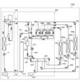
- FIG. 1 is a refrigerant circuit diagram showing a state of the air conditioner 1000 according to the first embodiment during full cooling operation.
- the air conditioner 1000 circulates a refrigerant in a refrigerant circuit and uses a refrigeration cycle to condition the air in a space to be air-conditioned.
- the air conditioner 1000 includes a heat source device 100, a plurality of indoor units 300a, 300b, and 300c, and a relay device 200.
- the air conditioner 1000 of this embodiment can perform cooling operation or heating operation for each of the plurality of indoor units 300a, 300b, and 300c.
- the air conditioner 1000 performs a full cooling operation in which a cooling operation is performed in all of the plurality of indoor units 300a, 300b, and 300c, and a full heating operation in which a heating operation is performed in all of the plurality of indoor units 300a, 300b, and 300c. is possible. Furthermore, the air conditioner 1000 according to the present embodiment is capable of performing simultaneous cooling and heating operations in which one of the plurality of indoor units 300a, 300b, and 300c performs a cooling operation, and one of the remaining indoor units performs a heating operation. be.
- simultaneous cooling and heating operations when the load of cooling operation is larger than the load of heating operation, it is called cooling-main operation, and when the load of heating operation is larger than the load of cooling operation, it is called heating-main operation.
- the number of heat source devices 100 and repeaters 200 may be two or more.
- the number of indoor units may be one, two, or four or more.
- the air conditioner 1000 is configured by connecting a heat source device 100, indoor units 300a to 300c, and a relay device 200.
- the heat source device 100 has a function of supplying heat to each of the indoor units 300a to 300c.
- the indoor units 300a to 300c are connected in parallel to the heat source device 100 and the relay device 200.
- the indoor units 300a to 300c have a function of cooling or heating a space to be air-conditioned, such as a room, using heat supplied from the heat source device 100.
- the relay device 200 is interposed between the heat source device 100 and the indoor units 300a to 300c, and switches the flow of refrigerant supplied from the heat source device 100 in response to a request from the indoor units 300a to 300c. It has the function of supplying
- the heat source device 100 and the relay device 200 are connected by a total of two refrigerant pipes, a gas main pipe 41 and a liquid main pipe 42, in a so-called liquid gas pipe connection manner.
- the gas main pipe 41 is a pipe through which gas refrigerant flows during both cooling operation and heating operation.
- the liquid main pipe 42 is a pipe through which liquid refrigerant or gas-liquid two-phase refrigerant flows during both cooling operation and heating operation.
- the repeater 200 and the indoor units 300a to 300c are each connected by a total of two refrigerant pipes. Specifically, the repeater 200 and the indoor unit 300a are connected through a gas branch pipe 43a and a liquid branch pipe 44a.
- the repeater 200 and the indoor unit 300b are connected by a gas branch pipe 43b and a liquid branch pipe 44b.
- the repeater 200 and the indoor unit 300c are connected by a gas branch pipe 43c and a liquid branch pipe 44c.
- Gaseous refrigerant mainly flows through the gas branch pipes 43a to 43c.
- a refrigerant mainly in a liquid state or a gas-liquid two-phase state flows through the liquid branch pipes 44a to 44c.
- the heat source device 100 includes a compressor 1 , a flow path switching valve 2 , a heat source side heat exchanger 3 , a heat source side flow control valve 4 , and a heat source device control device 5 .
- the compressor 1, the flow path switching valve 2, the heat source side heat exchanger 3, and the heat source side flow control valve 4 are connected by refrigerant piping shown in solid lines in FIG.
- the compressor 1 is a fluid machine that sucks in low-pressure gas refrigerant, compresses it, and discharges it as high-pressure gas refrigerant.
- the compressor 1 is, for example, an inverter-driven compressor whose operating frequency can be adjusted.
- the operating frequency or capacity of the compressor 1 is controlled by the heat source machine control device 5.
- the flow path switching valve 2 is a valve that switches the direction in which the refrigerant flows.
- the flow path switching valve 2 switches the direction in which the refrigerant discharged from the compressor 1 flows, depending on whether the full cooling operation, the main cooling operation, the full heating operation, or the main heating operation is performed.
- the flow path switching valve 2 is configured by a combination of a four-way valve, a two-way valve, a three-way valve, or the like. The operation of the flow path switching valve 2 is controlled by the heat source device control device 5.
- the heat source side heat exchanger 3 exchanges heat between the refrigerant flowing inside and another fluid.
- the heat source side heat exchanger 3 functions as an evaporator or a condenser.
- the heat source side heat exchanger 3 is, for example, an air-cooled heat exchanger, and exchanges heat with air from a blower disposed around the heat source side heat exchanger 3 and a refrigerant.
- the heat source side heat exchanger 3 may be a water-cooled heat exchanger that exchanges heat between water or brine and a refrigerant, for example.
- the heat source side flow control valve 4 is connected in series to the heat source side heat exchanger 3, and adjusts the flow rate of the refrigerant flowing through the refrigerant piping.
- the heat source side flow control valve 4 functions as a pressure reducing valve that reduces the pressure of the refrigerant and an expansion valve that expands the refrigerant.
- the heat source side flow control valve 4 is composed of, for example, an electric expansion valve whose opening degree can be adjusted. The operation of the heat source side flow control valve 4 is controlled by the heat source machine control device 5.
- the heat source device control device 5 controls the overall operation of the heat source device 100. Further, the heat source device control device 5 controls the operation of the entire air conditioner 1000 in cooperation with a repeater control device 201 and an indoor unit control device 33, which will be described later.
- the heat source device control device 5, the repeater control device 201, and the indoor unit control device 33 are connected to each other by a control line (not shown).
- the heat source equipment control device 5 is a computer, an ASIC (Application Specific Integrated Circuit), or an FPGA (Field Programmable Gate Array) that includes a memory that stores data and programs necessary for control, and a CPU (Central Processing Unit) that executes the programs. ), or both.
- the indoor unit 300a includes a load-side heat exchanger 31a, a load-side flow rate adjustment valve 32a, and an indoor unit control device 33a
- the indoor unit 300b includes a load-side heat exchanger 31b, a load-side flow rate adjustment valve 32b, and an indoor unit control device.
- the indoor unit 300c includes a load-side heat exchanger 31c, a load-side flow rate adjustment valve 32c, and an indoor unit control device 33c.
- the load side heat exchangers 31c to 31c will be referred to as the load side heat exchanger 31.
- the term "load-side heat exchanger 31" includes both singular and plural heat exchangers.
- the load side flow rate adjustment valves 32a to 32c will be referred to as load side flow rate adjustment valves 32.
- the term "load-side flow rate regulating valve 32" includes both singular and plural numbers.
- the indoor unit control devices 33a to 33c will be referred to as the indoor unit control device 33. When referring to the indoor unit control device 33, it shall include both the singular and plural.
- the load-side heat exchanger 31 exchanges heat between the refrigerant flowing inside and another fluid.
- the load side heat exchanger 31 functions as a condenser or an evaporator.
- the load-side heat exchanger 31 is, for example, an air-cooled heat exchanger, and exchanges heat with air from a blower disposed around the load-side heat exchanger 31 and a refrigerant.
- the load-side heat exchanger 31 may be a water-cooled heat exchanger that exchanges heat between water or brine and a refrigerant, for example.
- the load side flow rate adjustment valve 32 adjusts the flow rate of the refrigerant flowing into or out of the load side heat exchanger 31.
- the load side flow rate adjustment valve 32 functions as a pressure reducing valve that reduces the pressure of the refrigerant and an expansion valve that expands the refrigerant.
- the load-side flow rate adjustment valve 32 is composed of, for example, an electric expansion valve whose opening degree can be adjusted continuously or in multiple stages.
- the opening degree of the load side flow rate adjustment valve 32 is controlled by the indoor unit control device 33.
- the load side flow rate adjustment valve 32 is arranged upstream of the load side heat exchanger 31 in the flow direction of the refrigerant during full cooling operation.
- the indoor unit control device 33 controls the opening degree of the load-side flow rate adjustment valve 32 based on the control signal from the heat source device control device 5.
- the indoor unit control device 33 is composed of a computer including a CPU (Central Processing Unit) that executes a program, dedicated hardware such as an ASIC (Application Specific Integrated Circuit) or an FPGA (Field Programmable Gate Array), or both. be done.
- CPU Central Processing Unit
- ASIC Application Specific Integrated Circuit
- FPGA Field Programmable Gate Array
- the repeater 200 includes a repeater control device 201, a gas-liquid separator 202, and channel opening/closing devices 206a to 206c.
- the channel opening/closing devices 206a to 206c are provided in one-to-one correspondence with the indoor units 300a to 300c, and in this embodiment, a total of three channel opening/closing devices 206a to 206c are provided.
- the relay machine 200 of the present embodiment includes a first check valve 209, a second check valve 210, a check valve 211, a check valve 212, an on-off valve 213, and an on-off valve 214. ing.
- the relay device control device 201 controls the flow path opening/closing devices 206a to 206c, the first check valve 209, the second check valve 210, the check valve 211, and the check valve. 212, on-off valve 213, and on-off valve 214 are controlled.
- the repeater control device 201 is configured with a computer including a CPU (Central Processing Unit) that executes a program, dedicated hardware such as an ASIC (Application Specific Integrated Circuit) or an FPGA (Field Programmable Gate Array), or both. be done.
- CPU Central Processing Unit
- ASIC Application Specific Integrated Circuit
- FPGA Field Programmable Gate Array
- the gas-liquid separator 202 separates the refrigerant into gas refrigerant and liquid refrigerant.
- the gas-liquid separator 202 of this embodiment separates the high-pressure gas-liquid two-phase refrigerant generated by the heat source device 100 into liquid refrigerant and gas refrigerant when cooling-based operation is performed.
- the gas-liquid separator 202 is a container capable of storing a refrigerant, and has an inlet 203, a gas outlet 204, and a liquid outlet 205.
- the inlet 203 is connected to a pipe connected to the main liquid pipe 42 and allows the refrigerant that has flowed into the repeater 200 through the main liquid pipe 42 to flow into the gas-liquid separator 202 .
- the gas outlet 204 is provided above the gas-liquid separator 202 in the direction of gravity, and allows the gas refrigerant separated in the gas-liquid separator 202 to flow out from the gas-liquid separator 202 to the piping.
- the liquid outlet 205 is provided below the gas-liquid separator 202 in the direction of gravity, and allows the liquid refrigerant separated in the gas-liquid separator 202 to flow out from the gas-liquid separator 202 to the piping.
- the gas-liquid separator 202 is a container capable of storing a refrigerant
- a pipe may be used as the gas-liquid separator 202 instead of a container.
- the piping serving as the gas-liquid separator 202 may be branched to provide an inlet 203, a gas outlet 204, and a liquid outlet 205.
- the flow path opening/closing devices 206a to 206c are devices that open and close the refrigerant flow path from the heat source device 100 to the indoor units 300a to 300c and the refrigerant flow path from the indoor units 300a to 300c to the heat source device 100, respectively.
- the channel opening/closing device 206a includes a first valve 207a and a second valve 208a
- the channel opening/closing device 206b includes a first valve 207b and a second valve 208b
- the channel opening/closing device 206c includes a first valve 207c and a second valve 208b.
- a second valve 208c is provided.
- the channel opening/closing devices 206a to 206c when explaining matters common to the channel opening/closing devices 206a to 206c, the channel opening/closing devices 206a to 206c will be referred to as the channel opening/closing device 206.
- the first valves 207a to 207c when explaining matters common to the first valves 207a to 207c, the first valves 207a to 207c will be referred to as the first valve 207.
- the first valve 207 it shall include both the singular and the plural.
- the second valves 208a to 208c when describing matters common to the second valves 208a to 208c, the second valves 208a to 208c will be referred to as the second valve 208.
- Reference to the second valve 208 shall include both the singular and the plural.
- the flow path opening/closing device 206 has a first valve 207 and a second valve 208 connected in parallel to the indoor unit 300.
- the first valve 207 opens and closes the flow path between the first check valve 209 and the gas branch pipe 43.
- the first valve 207 is connected to a pipe that connects a pipe connected to the main gas pipe 41 and provided with the first check valve 209 and a pipe connected to the gas branch pipe 43. It is provided.
- the first valve 207 is an on-off valve that opens and closes a flow path for refrigerant flowing from the indoor unit 300 toward the heat source device 100.
- the second valve 208 opens and closes the flow path between the second check valve 210 and the gas branch pipe 43.
- the second valve 208 is provided in a pipe that connects the pipe connected to the main gas pipe 41 and provided with the second check valve 210 and the pipe connected to the gas branch pipe 43. .
- the second valve 208 is an on-off valve that opens and closes a flow path for refrigerant flowing from the heat source device 100 toward the indoor unit 300.
- the first valve 207 and the second valve 208 are, for example, electromagnetic valves or throttle valves with a fully closing function and adjustable opening, but the specific valve structure is not limited as long as it is possible to open and close the flow path. . When one of the first valve 207 and the second valve 208 is open, the other is closed, and both are never open.
- the first check valve 209 is provided in a pipe connected to the main gas pipe 41, allows the flow of refrigerant from the indoor unit 300 to the heat source device 100, and blocks the flow of refrigerant from the heat source device 100 to the indoor unit 300. do.
- the first check valve 209 prevents high-temperature and high-pressure gas refrigerant from flowing back from the flow path on the discharge side of the compressor 1 to the flow path opening/closing device 206 when full heating operation and heating-main operation are performed. This is to prevent
- the second check valve 210 is provided in a pipe connected to the main gas pipe 41 in parallel with the first check valve 209, and allows the refrigerant to flow from the heat source device 100 to the indoor unit 300. The flow of refrigerant to the heat source device 100 is cut off.
- the second backflow prevention valve 210 is configured so that when a cooling-only operation or a cooling-mainly operation is performed, refrigerant in a high-pressure liquid state or a gas-liquid two-phase state that has passed through the gas-liquid separator 202 is connected to the first backflow prevention valve 209 . This prevents the refrigerant from flowing back into the refrigerant pipe on the outlet side, that is, into the main gas pipe 41.
- the non-return valve 211 is provided in a pipe connecting the inlet side of the first non-return valve 209 and the main liquid pipe 42, and allows the refrigerant to flow from the indoor unit 300 to the heat source device 100. The flow of refrigerant to the indoor unit 300 is cut off.
- the check valve 211 prevents refrigerant in a high-pressure liquid state or a gas-liquid two-phase state from flowing into the outdoor unit 101 from the liquid main pipe 42 when all-cooling operation and cooling-mainly operation are performed. .
- the check valve 212 is provided in a pipe that connects the inlet 203 of the gas-liquid separator 202 and the main liquid pipe 42, and allows the refrigerant to flow from the heat source device 100 to the indoor unit 300. The flow of refrigerant to the heat source device 100 is cut off.
- the backflow prevention valve 212 prevents high-temperature, high-pressure gas refrigerant from flowing into the heat source side heat exchanger 3 when the heating-only operation and the heating-main operation are performed.
- the on-off valve 213 is provided in the pipe 241 connected to the liquid outlet 205 of the gas-liquid separator 202, and opens and closes the refrigerant flow path.
- the on-off valve 213 is, for example, a solenoid valve.
- the on-off valve 214 is provided in a pipe through which the liquid refrigerant flowing out from the liquid branch pipe 44 flows when the heating-only operation or the heating-main operation is performed, and opens and closes the flow path of the refrigerant.
- an on-off valve 214 is provided in a pipe 240 that connects the inlet side of the first check valve 209 and the liquid branch pipe 44 .
- the pipe 240 is a single pipe that is connected to the plurality of liquid branch pipes 44 via a pipe 243 and a pipe 244.
- Piping 240 and piping 241 intersect at intersection 242.
- the refrigerant in the pipe 240 and the refrigerant in the pipe 241 flow together or diverge at the intersection 242 depending on the open/close states of the on-off valve 213 and the on-off valve 214.
- the operations of the second valve 208 and the first valve 207, the first check valve 209, the second check valve 210, the check valve 211, the check valve 212, the on-off valve 213, and the on-off valve 214 of the flow path opening/closing device 206 are as follows. , is controlled by the repeater control device 201.
- the pipe connected to the main gas pipe 41 is branched into two, one pipe is provided with a first check valve 209, and the other pipe is provided with a second check valve 210.
- a pipe connected to the check valve 211 and a pipe connected to the first valve 207 are connected to the pipe 240 on the inlet side of the first check valve 209 to which the first check valve 209 is connected.
- On the outflow side of the second check valve 210 of the pipe to which the second check valve 210 is connected there is a pipe 245 connected to the gas outlet 204 of the gas-liquid separator 202, a pipe connected to the second valve 208, is connected.
- Piping 240 and piping 241 intersect at intersection 242, and further branch into piping 243 and piping 244. All the liquid branch pipes 44 are connected to the pipe 243, and all the liquid branch pipes 44 are also connected to the pipe 244.
- refrigerant In the air conditioner 1000, refrigerant is filled inside the piping.
- Refrigerants include, but are not particularly limited to, natural refrigerants such as carbon dioxide, hydrocarbons, and helium, chlorine-free fluorocarbon alternative refrigerants such as HFC410A, HFC407C, and HFC404A, or fluorocarbons used in existing products such as R22 and R134a. system refrigerant, etc.
- FIGS. 1 to 4 The operation of air conditioner 1000 will be explained with reference to FIGS. 1 to 4.
- the flow of refrigerant is indicated by arrows.
- the on-off valves shown in FIGS. 1 to 4 the on-off valves through which refrigerant does not flow are shown in black.
- a low-temperature, low-pressure refrigerant is sucked into the compressor 1, compressed, and discharged from the compressor 1 as a high-temperature, high-pressure gas refrigerant.
- the high-temperature, high-pressure gas refrigerant discharged from the compressor 1 passes through the flow path switching valve 2 and is condensed and liquefied by exchanging heat with a fluid such as air in the heat source side heat exchanger 3 that functions as a condenser or a radiator.
- the high-pressure liquid refrigerant then passes through the heat source side flow control valve 4, flows through the liquid main pipe 42, and flows into the repeater 200.
- the refrigerant that has flowed into the relay machine 200 passes through the check valve 212 and reaches the inside of the gas-liquid separator 202 from the inlet 203.
- the high-pressure liquid refrigerant that has flowed into the gas-liquid separator 202 flows out from the liquid outlet 205 and passes through the open/close valve 213 provided in the pipe 241 .
- the refrigerant flowing through the pipe 241 passes through the pipe 243 and the pipe 244, and branches into each of the liquid branch pipes 44a to 44c.
- the refrigerant flowing through each of the liquid branch pipes 44a to 44c flows into each of the indoor units 300a to 300c.
- the refrigerant that has flowed into the indoor units 300a to 300c is reduced in pressure by the load side flow rate adjustment valves 32a to 32c, respectively.
- the refrigerant which has been reduced in pressure and has become a low-temperature, low-pressure gas-liquid two-phase state, flows into the load-side heat exchangers 31a to 31c, which function as evaporators, and exchanges heat with indoor air in the load-side heat exchangers 31a to 31c. Evaporates into gas.
- the air-conditioned space such as the indoor space in which the indoor units 300a to 300c are installed, is cooled.
- the refrigerant which has become a low-temperature, low-pressure gas, flows into the channel opening/closing devices 206a to 206c of the repeater 200 through the gas branch pipes 43a to 43c, respectively.
- the first valves 207a to 207c are in an open state, and the second valves 208a to 208c are in a closed state.
- the refrigerant that has flowed into each of the channel opening/closing devices 206a to 206c passes through each of the first valves 207a to 207c, further passes through the first check valve 209, and flows out from the repeater 200.
- the gas refrigerant flowing out from the relay device 200 flows into the heat source device 100 through the gas main pipe 41.
- the refrigerant that has flowed into the heat source device 100 passes through the flow path switching valve 2 and is sucked into the compressor 1 .
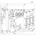
- FIG. 2 is a refrigerant circuit diagram showing a state in which the air conditioner 1000 according to the first embodiment is operating mainly for cooling.
- the indoor unit 300a performs a heating operation
- the indoor units 300b and 300c perform a cooling operation.
- the load for cooling operation is for two indoor units 300b and 300c, while the load for heating operation is for one indoor unit 300a, so the load for cooling operation is greater than the load for heating operation. It's also big.
- the refrigerant flow path of the flow path switching valve 2 is set such that the discharge side of the compressor 1 is connected to the heat source side heat exchanger 3.
- a low-temperature, low-pressure refrigerant is sucked into the compressor 1, compressed, and discharged from the compressor 1 as a high-temperature, high-pressure gas refrigerant.
- the high-temperature, high-pressure gas refrigerant discharged from the compressor 1 passes through the flow path switching valve 2 and exchanges heat with a fluid such as air in the heat source side heat exchanger 3 that functions as a condenser or radiator to form a gas-liquid two-phase gas refrigerant. become a state.
- the high-pressure gas-liquid two-phase refrigerant then passes through the heat source side flow control valve 4, flows through the liquid main pipe 42, and flows into the repeater 200.
- the refrigerant that has flowed into the relay machine 200 passes through the check valve 212 and reaches the inside of the gas-liquid separator 202 from the inlet 203.
- the gas-liquid separator 202 the gas-liquid two-phase refrigerant is separated into a gaseous refrigerant and a liquid refrigerant.
- the gaseous refrigerant flowing out from the gas outlet 204 of the gas-liquid separator 202 passes through the second valve 208a and flows into the indoor unit 300a through the gas branch pipe 43a.
- the refrigerant that has flowed into the indoor unit 300a exchanges heat with indoor air in the load-side heat exchanger 31a, which functions as a condenser or a radiator, and is condensed and liquefied.
- the air-conditioned space such as the indoor space in which the indoor unit 300a is installed, is heated.
- the high-pressure liquid refrigerant flows out of the load-side heat exchanger 31a and passes through the load-side flow rate adjustment valve 32a.
- the load side flow rate adjustment valve 32a Although the load side flow rate adjustment valve 32a is in a fully open state, the refrigerant is slightly depressurized when passing through the load side flow rate adjustment valve 32a.
- the refrigerant that has passed through the load-side flow rate adjustment valve 32a flows into the repeater 200 through the liquid branch pipe 44a, and flows through the pipes 243 and 244.
- the liquid refrigerant flowing out from the liquid outlet 205 of the gas-liquid separator 202 passes through the open on-off valve 213 provided in the pipe 241, passes through the intersection 242, and flows into the pipes 243 and 244.
- the liquid refrigerant from the liquid branch pipe 44a and the liquid refrigerant from the pipe 241 join together, and this liquid refrigerant flows into the indoor unit 300b or 300c through the liquid branch pipe 44b or 44c. .
- the refrigerant that has flowed into the indoor unit 300b or 300c is reduced in pressure by the load-side flow rate adjustment valve 32b or 32c, respectively, and enters a gas-liquid two-phase state.
- the decompressed gas-liquid two-phase refrigerant flows into the load-side heat exchanger 31b or 31c functioning as an evaporator, exchanges heat with indoor air in the load-side heat exchanger 31b or 31c, and evaporates into gas.
- the air-conditioned space such as the indoor space where the indoor units 300b and 300c are installed, is cooled.
- the refrigerant in a low-temperature, low-pressure gas state flows into the channel opening/closing device 206b or 206c of the repeater 200 through the gas branch pipe 43b or 43c, respectively.
- the amount of refrigerant flowing into the indoor unit 300 performing the cooling operation and the amount of refrigerant flowing into the indoor unit 300 performing the heating operation can be adjusted by adjusting the amount of heat exchange in the heat source side heat exchanger 3. Realized.
- the capacity of the compressor 1 is increased and the amount of gas refrigerant flowing out from the heat source side heat exchanger 3 increases, and the amount of gas refrigerant flowing out from the gas-liquid separator 202 is increased.
- the amount of gas refrigerant flowing into the machine 300 also increases.
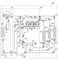
- FIG. 3 is a refrigerant circuit diagram showing a state of the air conditioner 1000 according to the first embodiment during full heating operation.
- all indoor units 300a to 300c perform heating operation.
- the refrigerant flow path of the flow path switching valve 2 is set such that the discharge side of the compressor 1 is connected to the main gas pipe 41 .
- a low-temperature, low-pressure refrigerant is sucked into the compressor 1, compressed, and discharged from the compressor 1 as a high-temperature, high-pressure gas refrigerant.
- the high-temperature, high-pressure gas refrigerant discharged from the compressor 1 passes through the flow path switching valve 2, flows through the gas main pipe 41, and flows into the repeater 200.
- the high-temperature, high-pressure gas refrigerant that has flowed into the repeater 200 passes through the second check valve 210 and flows into each of the channel opening/closing devices 206a to 206c.
- the second valves 208a to 208c are in an open state
- the first valves 207a to 207c are in a closed state.
- the refrigerant that has flowed into each of the flow path opening/closing devices 206a to 206c passes through each of the second valves 208a to 208c, further passes through each of the gas branch pipes 43a to 43c, and flows into each of the indoor units 300a to 300c. do.
- the gas refrigerant that has flowed into each of the indoor units 300a to 300c exchanges heat with indoor air in the load side heat exchangers 31a to 31c, which function as condensers or radiators, and is condensed and liquefied.
- the air-conditioned space such as the indoor space in which the indoor units 300a to 300c are installed, is heated.
- the pressure of the liquid refrigerant flowing out from each of the indoor units 300a to 300c is reduced by each of the load side flow rate adjustment valves 32a to 32c.
- the low-pressure liquid refrigerant then flows into the repeater 200 through each of the liquid branch pipes 44a to 44c.
- the downstream side of the on-off valve 214 and the downstream side of the first check valve 209 communicate with each other, but the first valve that communicates with the discharge side of the compressor 1 While the downstream side of the check valve 209 has a high pressure, the refrigerant flowing through the on-off valve 214 has a low pressure. Therefore, other refrigerant flowing through the on-off valve 214 does not pass through the first check valve 209 . Then, the low-pressure liquid refrigerant passes through the on-off valve 214 in the open state and the check valve 211, and flows out from the relay machine 200.
- the liquid refrigerant flowing out from the relay machine 200 flows into the heat source machine 100 through the liquid main pipe 42.
- the refrigerant that has flowed into the heat source device 100 passes through the heat source side flow control valve 4 and flows into the heat source side heat exchanger 3 that functions as an evaporator.
- the low-pressure liquid refrigerant exchanges heat with a fluid such as air in the heat source side heat exchanger 3, absorbs heat, and evaporates into gas.
- the low-pressure gas refrigerant that has flowed out of the heat source side heat exchanger 3 passes through the flow path switching valve 2 and is sucked into the compressor 1 .
- FIG. 4 is a refrigerant circuit diagram showing a state of the air conditioner 1000 according to the first embodiment when the air conditioner 1000 is mainly operated for heating.
- the indoor unit 300a performs a cooling operation
- the indoor units 300b and 300c perform a heating operation.
- the load for heating operation is for two indoor units 300b and 300c, while the load for cooling operation is for one indoor unit 300a, so the load for heating operation is greater than the load for cooling operation. It's also big.
- the refrigerant flow path of the flow path switching valve 2 is set such that the discharge side of the compressor 1 is connected to the main gas pipe 41 .
- a low-temperature, low-pressure refrigerant is sucked into the compressor 1, compressed, and discharged from the compressor 1 as a high-temperature, high-pressure gas refrigerant.
- the high-temperature, high-pressure gas refrigerant discharged from the compressor 1 passes through the flow path switching valve 2, flows through the gas main pipe 41, and flows into the repeater 200.
- the high-temperature, high-pressure gas refrigerant that has flowed into the repeater 200 passes through the second check valve 210 and flows into each of the channel opening/closing devices 206a to 206c.
- the second valves 208b and 208c are in an open state, and the second valve 208a is in a closed state.
- the first valve 207a is in an open state, and the first valves 207b and 207c are in a closed state.
- the gas refrigerant that has flowed into the channel opening/closing device 206b or 206c passes through the second valve 208b or 208c, respectively, and flows into the indoor unit 300b or 300c through the gas branch pipe 43b or 43c.
- the high-pressure gas refrigerant that has flowed into the indoor unit 300b or 300c exchanges heat with indoor air in the load-side heat exchanger 31b or 31c, which functions as a condenser or a radiator, respectively, and is condensed and liquefied. At that time, an air-conditioned space such as an indoor space in which the indoor unit 300b or 300c is installed is heated.
- the high-pressure liquid refrigerant flows out from the load-side heat exchanger 31b or 31c, and is reduced in pressure to a low pressure by the load-side flow rate adjustment valve 32b or 32c, respectively, and becomes a low-temperature, low-pressure gas-liquid two-phase refrigerant.
- the gas-liquid two-phase refrigerant that has passed through the load-side flow rate adjustment valve 32b or 32c passes through the liquid branch pipe 44b or 44c, flows into the repeater 200, and flows through the pipe 243 or 244.
- gas-liquid two-phase refrigerant that has flowed into the pipe 243 or the pipe 244 flows into the indoor unit 300a through the liquid branch pipe 44a, and the remaining refrigerant flows through the pipe 240 from the intersection 242 and continues into the open state. It passes through the on-off valve 214.
- the gas-liquid two-phase refrigerant that has flowed into the indoor unit 300a is depressurized at the load-side flow rate adjustment valve 32a, exchanges heat with indoor air at the load-side heat exchanger 31a that functions as an evaporator, and is evaporated into gas. .
- the air-conditioned space such as the indoor space in which the indoor unit 300a is installed, is cooled.
- the gas refrigerant flowing out from the load-side heat exchanger 31a flows into the channel opening/closing device 206a through the gas branch pipe 43a.
- the gas refrigerant that has flowed into the flow path opening/closing device 206a passes through the first valve 207a, merges with the gas-liquid two-phase refrigerant that has passed through the opening/closing valve 214, and passes through the backflow prevention valve 211 as a gas-liquid two-phase refrigerant. pass through.
- the gas-liquid two-phase refrigerant that has passed through the check valve 211 flows out from the repeater 200 .
- the gas-liquid two-phase refrigerant flowing out from the relay machine 200 flows into the heat source machine 100 through the liquid main pipe 42.
- the refrigerant that has flowed into the heat source device 100 passes through the heat source side flow control valve 4 and flows into the heat source side heat exchanger 3 that functions as an evaporator.
- the refrigerant flowing into the heat source side heat exchanger 3 exchanges heat with a fluid such as air in the heat source side heat exchanger 3, absorbs heat, and becomes a low temperature, low pressure gas refrigerant.
- the low-temperature, low-pressure gas refrigerant that has flowed out of the heat source side heat exchanger 3 is sucked into the compressor 1 through the flow path switching valve 2 .
- high-temperature, high-pressure gas refrigerant is sent to the relay device 200 from one of the indoor units 300a to 300c without passing through the gas-liquid separator 202.
- a path for the refrigerant to flow into is formed. Since the gas refrigerant does not pass through the gas-liquid separator 202, no pressure loss of the gas refrigerant occurs in the gas-liquid separator 202. Therefore, a decrease in the performance of the air conditioner 1000 due to the pressure loss of the refrigerant in the gas-liquid separator 202 can be avoided.
- the air conditioner 1000 of the present embodiment includes a heat source device 100 having a compressor 1, a flow path switching valve 2, and a heat source side heat exchanger 3, one or more indoor units 300, and a relay device 200. Equipped with.
- One or more indoor units 300 have a load-side flow rate adjustment valve 32 and a load-side heat exchanger 31, and perform cooling operation or heating operation.
- the relay device 200 is connected to the heat source device 100 by a gas main pipe 41 through which a gas refrigerant flows during cooling and heating operations, and a liquid main pipe 42 through which a liquid refrigerant or a gas-liquid two-phase refrigerant flows during cooling and heating operations.
- the relay device 200 is connected to the indoor unit 300 through a gas branch pipe 43 and a liquid branch pipe 44, and supplies the indoor unit 300 with the refrigerant supplied from the heat source device 100. Furthermore, the relay device 200 includes a gas-liquid separator 202 that separates the refrigerant into a gas refrigerant and a liquid refrigerant, a refrigerant flow path from the heat source device 100 to the indoor unit 300, and a refrigerant flow path from the indoor unit 300 to the heat source device 100. It includes one or more channel opening/closing devices 206 that open and close the channels, respectively.
- the refrigerant that has flowed into the relay device 200 from the heat source device 100 through the gas main pipe 41 is stored in the relay device 200 without passing through the gas-liquid separator 202. It has a path for the refrigerant to flow into the channel opening/closing device 206.
- the air conditioner 1000 of this embodiment when the heating operation is performed, the high temperature and high pressure gas refrigerant flows into the indoor unit 300 without passing through the gas-liquid separator 202. Since the gas refrigerant does not pass through the gas-liquid separator 202, no pressure loss of the gas refrigerant occurs in the gas-liquid separator 202. Therefore, a decrease in the performance of the air conditioner 1000 due to the pressure loss of the refrigerant in the gas-liquid separator 202 can be avoided.
- the one or more indoor units 300 are a plurality of indoor units 300a to 300c
- the flow path opening/closing device 206 is a plurality of flow paths that are the same number as the plurality of indoor units 300.
- These are opening/closing devices 206a to 206c.
- the plurality of airflows are arranged so that the cooling operation by one or more of the plurality of indoor units 300a to 300c and the heating operation by one or more of the other one or more of the plurality of indoor units 300a to 300c are performed simultaneously.
- the road switching devices 206a to 206c are controlled.
- the relay device 200 of the air conditioner 1000 of the present embodiment is provided in a pipe connected to the gas main pipe 41, allows the refrigerant to flow from the indoor unit 300 to the heat source device 100, and allows the refrigerant to flow from the indoor unit 300 to the heat source device 100.
- a first check valve 209 that blocks the flow of refrigerant to the machine 300 is provided.
- the relay device 200 is provided in parallel with the first check valve 209 in a pipe connected to the gas main pipe 41, and allows the flow of refrigerant from the heat source device 100 to the indoor unit 300, and allows the refrigerant to flow from the indoor unit 300 to the heat source device.
- a second check valve 210 that blocks the flow of refrigerant to 100 is provided.
- the refrigerant outlet of the second check valve 210 is connected to the piping connecting each of the plurality of flow path opening/closing devices 206a to 206c and the gas outlet 204 from which the gas refrigerant of the gas-liquid separator 202 flows out.
- a pipe 245 is connected thereto.
- the air conditioner 1000 of this embodiment includes the first check valve 209 as described above. Therefore, it is possible to prevent high-temperature and high-pressure gas refrigerant from flowing back from the flow path on the discharge side of the compressor 1 to the flow path opening/closing device 206 when the heating-only operation or the heating-based operation is performed. can.
- the air conditioner 1000 of the embodiment includes the second check valve 210 as described above. Therefore, even if the refrigerant in the high-pressure liquid state or gas-liquid two-phase state that has passed through the gas-liquid separator 202 flows into the pipe 245 when the cooling-only operation or the cooling-mainly operation is performed, the second backflow prevention The valve 210 blocks the flow. This prevents the high-pressure liquid or gas-liquid two-phase refrigerant that has passed through the gas-liquid separator 202 from flowing back into the refrigerant pipe on the outlet side of the first check valve 209, that is, into the main gas pipe 41. can do.
- Embodiment 2 a configuration including a pressure relief valve 215 in addition to the circuit configuration shown in Embodiment 1 will be described. In this embodiment, differences from Embodiment 1 will be mainly described, and descriptions of matters common to Embodiment 1 will be omitted as appropriate.
- FIG. 5 is a refrigerant circuit diagram showing the state of the air conditioner 1000A according to the second embodiment during full cooling operation.
- the air conditioner 1000A includes a pressure relief valve provided in the pipe connecting the pipe connected to the gas outlet 204 of the gas-liquid separator 202 and the pipe connected to the main gas pipe 41 in the repeater 200. It is equipped with 215.
- the pressure relief valve 215 is an on-off valve whose open/close state is controlled by the repeater control device 201.
- Pressure relief valve 215 is connected to piping 250, which is a high pressure line connected to second valves 208a-208c.
- the pressure relief valve 215 becomes open when the pressure of the refrigerant in the pipe 250 connecting the gas-liquid separator 202 and the second valves 208a to 208c becomes equal to or higher than the saturation pressure of the refrigerant.
- the pressure relief valve 215 is closed when the pressure of the refrigerant in the pipe 250 is less than the saturation pressure of the refrigerant.
- the open/close state of the pressure relief valve 215 is controlled by the repeater control device 201.
- FIGS. 5 to 8 The operation of the air conditioner 1000A will be explained with reference to FIGS. 5 to 8.
- the flow of refrigerant is indicated by arrows.
- the on-off valves shown in FIGS. 5 to 8 the on-off valves through which refrigerant does not flow are shown in black.
- FIG. 5 is a refrigerant circuit diagram showing a state of full cooling operation of the air conditioner 1000A according to the second embodiment.
- the pressure relief valve 215 operates as follows in the full cooling operation. That is, the pressure relief valve 215 becomes open when the pressure of the refrigerant in the pipe 250 connecting the gas-liquid separator 202 and the second valves 208a to 208c becomes equal to or higher than the saturation pressure of the refrigerant.
- the pressure relief valve 215 is closed when the pressure of the refrigerant in the pipe 250 is less than the saturation pressure of the refrigerant.
- the pressure relief valve 215 is set to the open state when the pressure of the piping 250, which is a high pressure line, becomes equal to or higher than the saturation pressure of the refrigerant. Established. Therefore, the refrigerant circuit of the air conditioner 1000A does not exceed the saturation pressure of the refrigerant. Therefore, the safety of the air conditioner 1000A can be improved.
- the pressure relief valve 215 may be periodically opened. By doing so, the refrigerant circuit of the air conditioner 1000A does not exceed the saturation pressure of the refrigerant. Therefore, the safety of the air conditioner 1000A can be improved.
- FIG. 6 is a refrigerant circuit diagram showing a state in which the air conditioner 1000A according to the second embodiment is mainly operated for cooling.
- indoor unit 300a performs heating operation
- indoor units 300b and 300c perform cooling operation.
- the load for cooling operation is for two indoor units 300b and 300c, while the load for heating operation is for one indoor unit 300a, so the load for cooling operation is greater than the load for heating operation. It's also big.
- the pressure relief valve 215 operates as follows. That is, the pressure relief valve 215 becomes open when the pressure of the refrigerant in the pipe 250 connecting the gas-liquid separator 202 and the second valves 208a to 208c becomes equal to or higher than the saturation pressure of the refrigerant. The pressure relief valve 215 is closed when the pressure of the refrigerant in the pipe 250 is less than the saturation pressure of the refrigerant.
- the pressure relief valve 215 is set to open when the pressure of the piping 250, which is a high pressure line, becomes equal to or higher than the saturation pressure of the refrigerant when the cooling-based operation is performed.
- the refrigerant circuit of the air conditioner 1000A does not exceed the saturation pressure of the refrigerant. Therefore, the safety of the air conditioner 1000A can be improved.
- FIG. 7 is a refrigerant circuit diagram showing a state of full heating operation of the air conditioner 1000A according to the second embodiment.
- all indoor units 300a to 300c perform heating operation.
- Air conditioner 1000A shown in FIG. 7 performs the operation shown in Embodiment 1 in full heating operation.
- the pressure relief valve 215 of the repeater 200 is always in a fully closed state.
- FIG. 8 is a refrigerant circuit diagram showing a state of the air conditioner 1000A according to the second embodiment when the air conditioner 1000A is mainly operating for heating.
- the indoor unit 300a performs a cooling operation
- the indoor units 300b and 300c perform a heating operation.
- Air conditioner 1000A shown in FIG. 8 performs the operation shown in Embodiment 1 in heating-based operation.
- the pressure relief valve 215 of the repeater 200 is always in a fully closed state.
- the air conditioner 1000A of this embodiment includes the pressure relief valve 215 provided in the pipe that communicates the main gas pipe 41 with the gas outlet 204 of the gas-liquid separator 202.
- the pressure relief valve 215 is connected to each of the flow path opening/closing devices 206a to 206c and the gas outlet 204 through which the gas refrigerant of the gas-liquid separator 202 flows out when one or more of the plurality of indoor units 300 is performing cooling operation.
- the refrigerant pressure in the pipe 250 connecting the refrigerant becomes equal to or higher than the saturation pressure of the refrigerant, the open state is established. Therefore, the refrigerant circuit of the air conditioner 1000A does not exceed the saturation pressure of the refrigerant. Therefore, the safety of the air conditioner 1000A can be improved.
- the pressure relief valve 215 of the air conditioner 1000A allows the gas refrigerant from each of the plurality of channel opening/closing devices 206a to 206c and the gas-liquid separator 202 to flow out when the cooling-only operation or the cooling-mainly operation is performed.
- the pressure of the refrigerant in the pipe connecting to the gas outlet 204 is less than the saturation pressure of the refrigerant, it may be periodically opened. By doing so, the refrigerant circuit of the air conditioner 1000A does not exceed the saturation pressure of the refrigerant. Therefore, the safety of the air conditioner 1000A can be improved.
- Embodiment 3 an air conditioner 1000B including a channel opening/closing device 223 different from those in Embodiments 1 and 2 will be described.
- the air conditioner 1000B of this embodiment further includes a refrigerant heat exchanger 226.
- differences from Embodiments 1 and 2 will be mainly described, and descriptions of matters common to Embodiments 1 and 2 will be omitted as appropriate.
- FIG. 9 is a refrigerant circuit diagram showing a state of the air conditioner 1000B according to the third embodiment during full cooling operation.
- the air conditioner 1000B is configured by connecting a heat source device 100, indoor units 300a to 300c, and a relay device 200.
- the heat source device 100 has a function of supplying heat to each of the indoor units 300a to 300c.
- Indoor units 300a to 300c are connected in parallel to each other.
- the indoor units 300a to 300c have a function of cooling or heating a space to be air-conditioned, such as a room, using heat supplied from the heat source device 100.
- the relay device 200 is interposed between the heat source device 100 and the indoor units 300a to 300c, and switches the flow of refrigerant supplied from the heat source device 100 in response to a request from the indoor units 300a to 300c. It has the function of supplying
- the heat source device 100 and the relay device 200 are connected by a total of two refrigerant pipes, a gas main pipe 41 and a liquid main pipe 42, in a so-called liquid gas pipe connection manner.
- the gas main pipe 41 is a pipe through which gas refrigerant flows during both cooling operation and heating operation.
- the liquid main pipe 42 is a pipe through which liquid refrigerant or gas-liquid two-phase refrigerant flows during both cooling operation and heating operation.
- the repeater 200 and the indoor units 300a to 300c are each connected by a total of two refrigerant pipes. Specifically, the repeater 200 and the indoor unit 300a are connected through a gas branch pipe 43a and a liquid branch pipe 44a.
- the repeater 200 and the indoor unit 300b are connected by a gas branch pipe 43b and a liquid branch pipe 44b.
- the repeater 200 and the indoor unit 300c are connected by a gas branch pipe 43c and a liquid branch pipe 44c.
- Gaseous refrigerant mainly flows through the gas branch pipes 43a to 43c.
- a refrigerant mainly in a liquid state or a gas-liquid two-phase state flows through the liquid branch pipes 44a to 44c.
- the configurations of the heat source device 100 and the indoor unit 300 are the same as in the first and second embodiments.
- the repeater 200 includes a repeater control device 201, a gas-liquid separator 202, and channel opening/closing devices 223a to 223c.
- the channel opening/closing devices 223a to 223c are provided in one-to-one correspondence with the indoor units 300a to 300c, and in this embodiment, a total of three channel opening/closing devices 223a to 223c are provided.
- the repeater 200 of this embodiment includes a low pressure pipe 220, a high pressure pipe 221, folded pipes 222a and 222b, a refrigerant heat exchanger 226, a first check valve 229, and a second check valve 230. and a third check valve 231.
- the low pressure pipe 220 is a pipe connected to a pipe connected to the main gas pipe 41 via a first check valve 229 .
- the low pressure pipe 220 is connected to each of the indoor units 300a to 300c via first valves 224a to 224b provided in each of the channel opening/closing devices 223a to 223c.
- the high-pressure pipe 221 is a pipe connected to a pipe connected to the main gas pipe 41 via a second check valve 230.
- the high pressure pipe 221 is connected to each of the indoor units 300a to 300c via second valves 225a to 225b provided in each of the channel opening/closing devices 223a to 223c.
- the folded pipes 222a and 222b are pipes connected to each of the indoor units 300a to 300c.
- the folded pipe 222a is connected to each of the liquid branch pipes 44a to 44c via the first indoor unit non-return valves 236a to 236c, respectively.
- the first backflow prevention valves 236a to 236c for indoor units allow the refrigerant to flow from the folded tube 222a to each of the indoor units 300a to 300c, and block the flow of refrigerant in the opposite direction.
- the folded tube 222a is connected to a folded tube 222b and a refrigerant heat exchanger 226 via piping.
- the folded pipe 222b is connected to each of the liquid branch pipes 44a to 44c via second check valves for indoor units 237a to 237c, respectively.
- the second backflow prevention valves 237a to 237c for indoor units allow the flow of refrigerant from each of the indoor units 300a to 300c to the folded tube 222b, and block the flow of refrigerant in the opposite direction.
- the first check valve 229 is provided in a pipe connected to the main gas pipe 41, allows the flow of refrigerant from the indoor unit 300 to the heat source device 100, and blocks the flow of refrigerant from the heat source device 100 to the indoor unit 300. do.
- the first check valve 229 prevents high-temperature and high-pressure gas refrigerant from flowing back from the flow path on the discharge side of the compressor 1 to the flow path opening/closing device 206 when full heating operation and heating-main operation are performed. This is to prevent
- the second check valve 230 is provided in a pipe connected to the main gas pipe 41 in parallel with the first check valve 229, and allows the refrigerant to flow from the heat source device 100 to the indoor unit 300. The flow of refrigerant to the heat source device 100 is cut off.
- the second backflow prevention valve 230 is configured such that when a cooling-only operation or a cooling-mainly operation is performed, the refrigerant in a high-pressure liquid state or a gas-liquid two-phase state that has passed through the gas-liquid separator 202 flows through the first backflow prevention valve 229. This prevents the refrigerant from flowing back into the refrigerant pipe on the outlet side, that is, into the main gas pipe 41.
- the flow path opening/closing devices 223a to 223c are devices that open and close the refrigerant flow path from the heat source device 100 to the indoor units 300a to 300c and the refrigerant flow path from the indoor units 300a to 300c to the heat source device 100, respectively.
- the channel opening/closing device 223a includes a first valve 224a and a second valve 225a
- the channel opening/closing device 223b includes a first valve 224b and a second valve 225b
- the channel opening/closing device 223c includes a first valve 224c and a second valve 225b.
- a second valve 225c is provided.
- the channel opening/closing devices 223a to 223c will be referred to as the channel opening/closing device 223.
- the first valves 224a to 224c will be referred to as the first valve 224.
- the second valves 225a to 225c will be referred to as second valves 225.
- the second valve 225 it shall include both the singular and the plural.
- the flow path opening/closing device 223 has a first valve 224 and a second valve 225 connected in parallel to the indoor unit 300.
- the first valve 224 is connected to the low pressure pipe 220.
- the first valve 224 opens and closes the flow path between the first check valve 229 and the gas branch pipe 43.
- the first valve 224 is an on-off valve that opens and closes a flow path for refrigerant flowing from the indoor unit 300 toward the heat source device 100.
- the second valve 225 is connected to the high pressure pipe 221.
- the second valve 225 opens and closes the flow path between the second check valve 230 and the gas branch pipe 43.
- the second valve 225 is an on-off valve that opens and closes a flow path for refrigerant flowing from the heat source device 100 toward the indoor unit 300.
- the first valve 224 and the second valve 225 are, for example, electromagnetic valves or throttle valves that have a fully closing function and whose opening can be adjusted, but the specific structure of the valves is not limited as long as it is possible to open and close the flow path. .
- the first valve 224 and the second valve 225 When one of the first valve 224 and the second valve 225 is open, the other is closed, and both are never open.
- the refrigerant heat exchanger 226 exchanges heat between the refrigerant flowing inside the repeater 200 and the refrigerant.
- the refrigerant heat exchanger 226 is provided in a pipe that connects the liquid outlet 205 of the gas-liquid separator 202 and the folded tubes 222a and 222b.
- a branch pipe 227 branches off from a branch portion 228 between the refrigerant heat exchanger 226 and the folded tubes 222a and 222b, and serves as a flow path for the refrigerant of the refrigerant heat exchanger 226.
- a third on-off valve 234 is provided in the branch pipe 227 between the branch portion 228 and the refrigerant heat exchanger 226 .
- a branch pipe 227 exiting the refrigerant heat exchanger 226 is connected to a high pressure pipe 221. Specifically, the end of the branch pipe 227 is connected to the high pressure pipe 221 on the outlet side of the second check valve 230 .
- a pipe 262 branches from between the connection portion between the refrigerant heat exchanger 226 and the high-pressure pipe 221 .
- the pipe 262 is connected to a pipe that connects the low pressure pipe 220 and the first check valve 229 .
- heat exchange is performed between the refrigerant flowing through the pipe 260 and the refrigerant flowing through the branch pipe 227 .
- the third on-off valve 234 is composed of, for example, an electric expansion valve whose opening degree can be adjusted.
- the operation of the third on-off valve 234 is controlled by the repeater control device 201.
- a first on-off valve 232 is provided in a pipe 260 that connects the folded pipes 222a and 222b and the liquid main pipe 42 via the gas-liquid separator 202 and the refrigerant heat exchanger 226.
- the first on-off valve 232 opens and closes the refrigerant flow path in the pipe 260.
- the first on-off valve 232 is composed of, for example, an electric expansion valve whose opening degree can be adjusted. The operation of the first on-off valve 232 is controlled by the repeater control device 201.
- a portion of the branch pipe 227 between the position where the pipe 262 branches from the branch pipe 227 and the end connected to the high pressure pipe 221 is referred to as a pipe 261.
- a third check valve 231 is provided in the pipe 261 .
- the third check valve 231 allows the refrigerant to flow from the branch pipe 227 of the refrigerant heat exchanger 226 to the high-pressure pipe 221, and blocks the refrigerant from flowing in the opposite direction.
- the piping 262 is provided with an on-off valve 235 for controlling valve pressure.
- an on-off valve 235 for controlling valve pressure.
- high-pressure refrigerant that is about to flow into the indoor unit 300 pushes the closed third on-off valve 234 and passes through it, and can flow into the high-pressure pipe 221 through the pipe 261.
- the refrigerant that has flowed into the high-pressure pipe 221 may lose its flow direction due to the second check valve 230, increase in pressure, and exceed the condensation pressure, thereby becoming liquid refrigerant. Therefore, a valve pressure control on-off valve 235 is provided in a pipe 262 that is provided in parallel to the pipe 261 on the downstream side of the third on-off valve 234 .
- valve pressure control on-off valve 235 is opened and closed so that the pressure of the refrigerant flowing through the pipe 261 does not exceed the condensation pressure. Thereby, accumulation of liquid refrigerant in the high-pressure pipe 221 can be suppressed.
- the opening degree of the valve pressure control on-off valve 235 is controlled by the repeater control device 201.
- a pipe 263 connected to the gas outlet 204 of the gas-liquid separator 202 is connected between the first check valve 229 and the valve pressure control on-off valve 235 of the pipe 262.
- a second on-off valve 233 is provided in the pipe 263.
- the second on-off valve 233 opens and closes the refrigerant flow path in the pipe 263.
- the second on-off valve 233 is composed of, for example, an electric expansion valve whose opening degree can be adjusted. The operation of the second on-off valve 233 is controlled by the repeater control device 201.
- the third check valve 231 is provided in the pipe 261, allows the refrigerant to flow from the branch pipe 227 of the refrigerant heat exchanger 226 toward the high-pressure pipe 221, and blocks the refrigerant from flowing in the opposite direction.
- FIGS. 9 to 12 The operation of the air conditioner 1000B will be explained with reference to FIGS. 9 to 12.
- the flow of refrigerant is indicated by arrows.
- the on-off valves shown in FIGS. 9 to 12 the on-off valves through which refrigerant does not flow are shown in black.
- the refrigerant flow path of the flow path switching valve 2 is set such that the discharge side of the compressor 1 is connected to the heat source side heat exchanger 3. As shown in FIG. 9, a low-temperature, low-pressure refrigerant is sucked into the compressor 1, compressed, and discharged from the compressor 1 as a high-temperature, high-pressure gas refrigerant.
- the high-temperature, high-pressure gas refrigerant discharged from the compressor 1 passes through the flow path switching valve 2 and is condensed and liquefied by exchanging heat with a fluid such as air in the heat source side heat exchanger 3 that functions as a condenser or a radiator.
- the high-pressure liquid refrigerant then passes through the heat source side flow control valve 4, flows through the liquid main pipe 42, and flows into the repeater 200.
- the refrigerant that has flowed into the repeater 200 flows into the gas-liquid separator 202 from the inlet 203 .
- the high-pressure liquid refrigerant that has flowed into the gas-liquid separator 202 flows out from the liquid outlet 205 and flows through the refrigerant heat exchanger 226.
- the third on-off valve 234 is in a closed state, and the refrigerant does not flow into the branch pipe 227.
- the opening degree of the valve pressure control on-off valve 235 is controlled so that the refrigerant in the pipe 261 does not exceed the condensation pressure.
- the refrigerant flowing out from the refrigerant heat exchanger 226 passes through the open first on-off valve 232 provided in the pipe 260 and flows into the folded pipe 222a.
- the refrigerant that has flowed into the folded pipe 222a passes through any one of the indoor unit first non-return valves 236a to 236c and flows through any one of the liquid branch pipes 44a to 44c.
- the refrigerant flowing through each of the liquid branch pipes 44a to 44c flows into each of the indoor units 300a to 300c.
- the refrigerant that has flowed into the indoor units 300a to 300c is reduced in pressure by the load side flow rate adjustment valves 32a to 32c, respectively.
- the depressurized refrigerant flows into the load-side heat exchangers 31a to 31c functioning as evaporators, exchanges heat with indoor air in the load-side heat exchangers 31a to 31c, and is evaporated into gas.
- the air-conditioned space such as the indoor space in which the indoor units 300a to 300c are installed, is cooled.
- the refrigerant in the gas state flows into the channel opening/closing devices 223a to 223c of the repeater 200 through the gas branch pipes 43a to 43c, respectively.
- the first valves 224a to 224b are in an open state, and the second valves 225a to 225b are in a closed state.
- the refrigerant that has flowed into each of the channel opening/closing devices 223a to 223c passes through each of the first valves 224a to 224b, further passes through the first check valve 229, and flows out from the repeater 200.
- the gas refrigerant flowing out from the relay device 200 flows into the heat source device 100 through the gas main pipe 41.
- the refrigerant that has flowed into the heat source device 100 passes through the flow path switching valve 2 and is sucked into the compressor 1 .
- FIG. 10 is a refrigerant circuit diagram showing a state of the air conditioner 1000B according to Embodiment 3 during cooling-mainly operation.
- the indoor unit 300a performs a heating operation
- the indoor units 300b and 300c perform a cooling operation.
- the load for cooling operation is for two indoor units 300b and 300c, while the load for heating operation is for one indoor unit 300a, so the load for cooling operation is greater than the load for heating operation. It's also big.
- the refrigerant flow path of the flow path switching valve 2 is set such that the discharge side of the compressor 1 is connected to the heat source side heat exchanger 3.
- a low-temperature, low-pressure refrigerant is sucked into the compressor 1, compressed, and discharged from the compressor 1 as a high-temperature, high-pressure gas refrigerant.
- the high-temperature, high-pressure gas refrigerant discharged from the compressor 1 passes through the flow path switching valve 2 and exchanges heat with a fluid such as air in the heat source side heat exchanger 3 that functions as a condenser or radiator to form a gas-liquid two-phase gas refrigerant. become a state.
- the high-pressure gas-liquid two-phase refrigerant then passes through the heat source side flow control valve 4, flows through the liquid main pipe 42, and flows into the repeater 200.
- the liquid refrigerant that has flowed into the repeater 200 flows into the gas-liquid separator 202 from the inlet 203 .
- the refrigerant is separated into a gaseous refrigerant and a liquid refrigerant.
- the liquid refrigerant flowing out from the liquid outlet 205 of the gas-liquid separator 202 passes through the refrigerant heat exchanger 226.
- a part of the refrigerant that has passed through the refrigerant heat exchanger 226 flows from the branch portion 228 to the branch pipe 227, and the remaining refrigerant flows toward the first on-off valve 232 provided in the pipe 260.
- the amount of refrigerant flowing from the downstream side of the refrigerant heat exchanger 226 to the branch pipe 227 is adjusted by the opening degree of the third on-off valve 234.
- the valve pressure control on-off valve 235 is in a closed state.
- the refrigerant that has flowed through the branch pipe 227 and the pipe 261 passes through the third check valve 231 and flows into the high pressure pipe 221.
- the refrigerant that has flowed into the high-pressure pipe 221 passes through the first valve 224a that is in an open state, further passes through the gas branch pipe 43a, and flows into the indoor unit 103a.
- the refrigerant that has flowed into the indoor unit 103a exchanges heat with indoor air in the load-side heat exchanger 31a, which functions as a condenser or a radiator, and is condensed and liquefied. At that time, the air-conditioned space, such as the indoor space in which the indoor unit 300a is installed, is heated.
- the high-pressure liquid refrigerant flows out of the load-side heat exchanger 31a and passes through the load-side flow rate adjustment valve 32a. Although the load side flow rate adjustment valve 32a is in a fully open state, the refrigerant is slightly depressurized when passing through the load side flow rate adjustment valve 32a. The refrigerant that has passed through the load-side flow rate adjustment valve 32a flows into the repeater 200 through the liquid branch pipe 44a.
- the refrigerant that has flowed into the repeater 200 flows into the return pipe 222b through the second indoor unit non-return valve 237a, and joins with the refrigerant that has passed through the first on-off valve 232 of the pipe 260.
- the combined refrigerant flows into the folded tube 222a.
- the refrigerant that has flowed into the folded pipe 222a passes through the first indoor unit non-return valve 236b or 236c and flows through the liquid branch pipe 44b or 44c.
- the refrigerant flowing through each of the liquid branch pipes 44b or 44c flows into the indoor unit 300b or 300c.
- the pressure of the refrigerant flowing into the indoor unit 300b or 300c is reduced by the load-side flow rate adjustment valve 32b or 32c, respectively.
- the depressurized refrigerant flows into the load-side heat exchangers 31b and 31c that function as evaporators, exchanges heat with indoor air in the load-side heat exchangers 31b and 31c, and is evaporated and gasified.
- the air-conditioned space such as the indoor space where the indoor units 300b and 300c are installed, is cooled.
- the refrigerant in the gas state flows into the channel opening/closing device 223b or 223c of the repeater 200 through the gas branch pipe 43b or 43c, respectively.
- the gas refrigerant that has flowed into the channel opening/closing device 223b or 223c passes through the first valve 224b or 224c, joins together at the low pressure pipe 220, passes through the first check valve 229, and flows out from the relay machine 200. .
- the gas refrigerant flowing out from the relay device 200 flows into the heat source device 100 through the gas main pipe 41.
- the refrigerant that has flowed into the heat source device 100 passes through the flow path switching valve 2 and is sucked into the compressor 1 .
- the amount of refrigerant flowing into the indoor unit 300 performing the cooling operation and the amount of refrigerant flowing into the indoor unit 300 performing the heating operation are adjusted by the amount of heat exchange in the heat source side heat exchanger 3. Ru.
- the required heating load increases, the capacity of the compressor 1 is increased, and the amount of gas refrigerant flowing from the gas-liquid separator 202 into the indoor unit 300 that performs heating operation increases.
- the required heating load becomes smaller, the capacity of the compressor 1 is reduced, and the amount of gas refrigerant flowing from the gas-liquid separator 202 into the indoor unit 300 that performs the heating operation is reduced.
- FIG. 11 is a refrigerant circuit diagram showing a state of the air conditioner 1000B according to the third embodiment during full heating operation.
- all indoor units 300a to 300c perform heating operation.
- the refrigerant flow path of the flow path switching valve 2 is set such that the discharge side of the compressor 1 is connected to the main gas pipe 41 .
- a low-temperature, low-pressure refrigerant is sucked into the compressor 1, compressed, and discharged from the compressor 1 as a high-temperature, high-pressure gas refrigerant.
- the high-temperature, high-pressure gas refrigerant discharged from the compressor 1 passes through the flow path switching valve 2, flows through the gas main pipe 41, and flows into the repeater 200.
- the high-temperature, high-pressure gas refrigerant that has flowed into the relay machine 200 passes through the second check valve 230 and flows into the high-pressure pipe 221.
- the refrigerant that has flowed into the high-pressure pipe 221 flows into each of the channel opening/closing devices 223a to 223c.
- the second valves 225a to 225c are in an open state
- the first valves 224a to 224c are in a closed state.
- each of the flow path opening/closing devices 223a to 223c passes through each of the first valves 224a to 224c, and further passes through each of the gas branch pipes 43a to 43c, and flows into each of the indoor units 300a to 300c. do.
- the gas refrigerant that has flowed into each of the indoor units 300a to 300c exchanges heat with indoor air in the load-side heat exchangers 31a to 31c, which function as condensers or radiators, respectively, and is condensed and liquefied.
- the air-conditioned space such as the indoor space in which the indoor units 300a to 300c are installed, is heated.
- the pressure of the liquid refrigerant flowing out from each of the indoor units 300a to 300c is reduced by each of the load side flow rate adjustment valves 32a to 32c.
- the low-pressure liquid refrigerant then flows into the repeater 200 through the liquid branch pipes 44a to 44c, respectively.
- the low-pressure liquid refrigerant that has flowed into the repeater 200 through the liquid branch pipes 44a to 44c passes through the indoor unit second check valves 237a to 237c and flows into the folded pipe 222b.
- the refrigerant flowing into the folded tube 222b passes through the first on-off valve 232, the refrigerant heat exchanger 226, and reaches the inside of the gas-liquid separator 202 from the liquid outlet 205.
- the third on-off valve 234 and the valve pressure control on-off valve 235 are in a closed state.
- the low-pressure liquid refrigerant that has flowed into the gas-liquid separator 202 flows out from the repeater 200.
- the liquid refrigerant flowing out from the relay machine 200 flows into the heat source machine 100 through the liquid main pipe 42.
- the refrigerant that has flowed into the heat source device 100 passes through the heat source side flow control valve 4 and flows into the heat source side heat exchanger 3 that functions as an evaporator.
- the low-pressure liquid refrigerant exchanges heat with a fluid such as air in the heat source side heat exchanger 3, absorbs heat, and evaporates into gas.
- the low-pressure gas refrigerant that has flowed out of the heat source side heat exchanger 3 passes through the flow path switching valve 2 and is sucked into the compressor 1 .
- the high temperature and high pressure gas refrigerant flows into each of the indoor units 300a to 300c without passing through the gas-liquid separator 202. Since the gas refrigerant does not pass through the gas-liquid separator 202, no pressure loss of the gas refrigerant occurs in the gas-liquid separator 202. Therefore, a decrease in the performance of the air conditioner 1000B due to the pressure loss of the refrigerant in the gas-liquid separator 202 can be avoided.
- FIG. 12 is a refrigerant circuit diagram showing a state in which air conditioner 1000B according to Embodiment 3 is operating mainly for heating.
- the indoor unit 300a performs a cooling operation
- the indoor units 300b and 300c perform a heating operation.
- the load for heating operation is for two indoor units 300b and 300c, while the load for cooling operation is for one indoor unit 300a, so the load for heating operation is greater than the load for cooling operation. It's also big.
- the refrigerant flow path of the flow path switching valve 2 is set such that the discharge side of the compressor 1 is connected to the main gas pipe 41 .
- a low-temperature, low-pressure refrigerant is sucked into the compressor 1, compressed, and discharged from the compressor 1 as a high-temperature, high-pressure gas refrigerant.
- the high-temperature, high-pressure gas refrigerant discharged from the compressor 1 passes through the flow path switching valve 2, flows through the gas main pipe 41, and flows into the repeater 200.
- the high-temperature, high-pressure gas refrigerant that has flowed into the relay machine 200 passes through the second check valve 230 and flows into each of the channel opening/closing devices 223a to 223c.
- the first valves 224b and 224c are in a closed state, and the first valve 224a is in an open state.
- the second valve 225a is in a closed state, and the second valves 225b and 225c are in an open state.
- the gas refrigerant that has flowed into the channel opening/closing device 223b or 223c passes through the second valve 225b or 225c, respectively, and flows into the indoor unit 300b or 300c through the gas branch pipe 43b or 43c.
- the high-pressure gas refrigerant that has flowed into the indoor unit 300b or 300c exchanges heat with indoor air in the load-side heat exchanger 31b or 31c, which functions as a condenser or a radiator, respectively, and is condensed and liquefied. At that time, an air-conditioned space such as an indoor space in which the indoor unit 300b or 300c is installed is heated.
- the high-pressure liquid refrigerant flows out from the load-side heat exchanger 31b or 31c, and is reduced in pressure to a low pressure by the load-side flow rate adjustment valve 32b or 32c, respectively, and becomes a low-temperature, low-pressure gas-liquid two-phase refrigerant.
- the two-phase refrigerant that has passed through the load-side flow rate adjustment valve 32b or 32c flows into the repeater 200 through the liquid branch pipe 44b or 44c.
- the low-pressure liquid refrigerant that has flowed into the repeater 200 through the liquid branch pipe 44b or 44c passes through the second indoor unit non-return valve 237b or 237c and flows into the folded pipe 222b.
- a part of the refrigerant that has flowed into the folded tube 222b passes through the first on-off valve 232, passes through the refrigerant heat exchanger 226, and reaches the inside of the gas-liquid separator 202 from the liquid outlet 205.
- the third on-off valve 234 and the valve pressure control on-off valve 235 are in a closed state.
- the remainder of the refrigerant that has flowed into the folded pipe 222b passes through the folded pipe 222a and the first indoor unit non-return valve 236a.
- the gas-liquid two-phase refrigerant that has passed through the first indoor unit check valve 236a flows into the indoor unit 300a through the liquid branch pipe 44a.
- the gas-liquid two-phase refrigerant that has flowed into the indoor unit 300a is depressurized at the load-side flow rate adjustment valve 32a, exchanges heat with indoor air at the load-side heat exchanger 31a that functions as an evaporator, and is evaporated into gas. .
- the air-conditioned space such as the indoor space in which the indoor unit 300a is installed, is cooled.
- the gas refrigerant flowing out from the load-side heat exchanger 31a flows into the channel opening/closing device 223a through the gas branch pipe 43a.
- the gas refrigerant that has flowed into the channel opening/closing device 223a passes through the first valve 224a and flows through the low pressure pipe 220.
- the refrigerant that has flowed through the low-pressure pipe 220 passes through the second on-off valve 233 of the pipe 262 and flows into the gas-liquid separator 202 through the gas outlet 204.
- the refrigerant in the gas-liquid separator 202 flows out from the repeater 200.
- the two-phase refrigerant flowing out from the relay machine 200 flows into the heat source machine 100 through the liquid main pipe 42.
- the refrigerant that has flowed into the heat source device 100 passes through the heat source side flow control valve 4 and flows into the heat source side heat exchanger 3 that functions as an evaporator.
- the low-pressure gas refrigerant exchanges heat with a fluid such as air in the heat source side heat exchanger 3, absorbs heat, and becomes a low-temperature, low-pressure gas refrigerant.
- the low-temperature, low-pressure gas refrigerant that has flowed out of the heat source side heat exchanger 3 is sucked into the compressor 1 through the flow path switching valve 2 .
- the high-temperature, high-pressure gas refrigerant flows into any of the indoor units 300a to 300c without passing through the gas-liquid separator 202. Since the gas refrigerant does not pass through the gas-liquid separator 202, no pressure loss of the gas refrigerant occurs in the gas-liquid separator 202. Therefore, a decrease in the performance of the air conditioner 1000 due to the pressure loss of the refrigerant in the gas-liquid separator 202 can be avoided.
- the constituent members of the air conditioners 1000 to 1000B are controlled by the heat source device control device 5, the repeater control device 201, and the indoor unit control device 33, respectively.
- the physical arrangement of the control devices that control the constituent members of air conditioners 1000 to 1000B is not limited to the examples illustrated in Embodiments 1 to 3.
- the components of the heat source device 100, the relay device 200, and the indoor unit 300 may be controlled by a control device provided in the heat source device 100.
Abstract
La présente invention concerne un dispositif de climatisation comprenant un machine de source de chaleur comportant un compresseur, un robinet de commutation de passage de flux et un échangeur thermique côté source de chaleur, une ou plusieurs unités intérieures qui comprennent un robinet de réglage de débit côté charge et un échangeur thermique côté charge et qui réalisent une opération de refroidissement d'espace ou une opération de chauffage d'espace, ainsi qu'une unité de relais qui est reliée à la machine de source de chaleur au moyen d'un tuyau principal de gaz à travers lequel s'écoule un fluide frigorigène gazeux lorsque l'opération de refroidissement d'espace et l'opération de chauffage d'espace sont effectuées, ainsi qu'une conduite principale de liquide à travers laquelle un liquide frigorigène ou un fluide frigorigène biphase gaz-liquide coule lorsque les opérations de refroidissement et de chauffage d'espace sont effectuées,l'unité de relais étant reliée à chacune de la ou des unités intérieures au moyen d'un tuyau de dérivation de gaz et d'un tuyau de dérivation de liquide et fournissant un fluide frigorigène fourni par la machine de source de chaleur à la ou aux machines intérieures, l'unité de relais comprenant un séparateur gaz-liquide pour séparer le fluide frigorigène en fluide frigorigène gazeux et fluide frigorigène liquide et un ou plusieurs dispositifs d'ouverture et de fermeture de passage d'écoulement pour ouvrir et fermer respectivement un passage d'écoulement de fluide frigorigène de la machine de source de chaleur vers la ou les unités intérieures et ouvrir et fermer un passage d'écoulement de fluide frigorigène à partir de la ou des unités intérieures vers la machine de source de chaleur ; et l'unité de relais comprenant un trajet de fluide frigorigène à travers lequel, le fluide frigorigène s'écoulant de la machine de source de chaleur à travers le tuyau principal de gaz dans l'unité de relais s'écoule dans le ou les dispositifs d'ouverture et de fermeture de passage d'écoulement sans passer à travers le séparateur gaz-liquide, lorsque l'opération de chauffage d'espace est réalisée, le fluide frigorigène passant de la machine de source de chaleur à travers la conduite principale de gaz dans l'unité de relais passant par le ou les dispositifs d'ouverture et de fermeture de passage d'écoulement sans passer par le séparateur gaz-liquide.
Priority Applications (1)
| Application Number | Priority Date | Filing Date | Title |
|---|---|---|---|
| PCT/JP2022/020941 WO2023223539A1 (fr) | 2022-05-20 | 2022-05-20 | Dispositif de climatisation |
Applications Claiming Priority (1)
| Application Number | Priority Date | Filing Date | Title |
|---|---|---|---|
| PCT/JP2022/020941 WO2023223539A1 (fr) | 2022-05-20 | 2022-05-20 | Dispositif de climatisation |
Publications (1)
| Publication Number | Publication Date |
|---|---|
| WO2023223539A1 true WO2023223539A1 (fr) | 2023-11-23 |
Family
ID=88835020
Family Applications (1)
| Application Number | Title | Priority Date | Filing Date |
|---|---|---|---|
| PCT/JP2022/020941 WO2023223539A1 (fr) | 2022-05-20 | 2022-05-20 | Dispositif de climatisation |
Country Status (1)
| Country | Link |
|---|---|
| WO (1) | WO2023223539A1 (fr) |
Citations (5)
| Publication number | Priority date | Publication date | Assignee | Title |
|---|---|---|---|---|
| JPS56102658A (en) * | 1980-01-18 | 1981-08-17 | Matsushita Electric Ind Co Ltd | Multiple chamber type air conditioner |
| JP2011033289A (ja) * | 2009-08-04 | 2011-02-17 | Panasonic Corp | 冷凍サイクル装置 |
| WO2013111176A1 (fr) * | 2012-01-23 | 2013-08-01 | 三菱電機株式会社 | Dispositif de climatisation |
| JP2014129976A (ja) * | 2012-12-28 | 2014-07-10 | Daikin Ind Ltd | 空気調和装置 |
| WO2015177896A1 (fr) * | 2014-05-21 | 2015-11-26 | 三菱電機株式会社 | Dispositif de climatisation |
-
2022
- 2022-05-20 WO PCT/JP2022/020941 patent/WO2023223539A1/fr unknown
Patent Citations (5)
| Publication number | Priority date | Publication date | Assignee | Title |
|---|---|---|---|---|
| JPS56102658A (en) * | 1980-01-18 | 1981-08-17 | Matsushita Electric Ind Co Ltd | Multiple chamber type air conditioner |
| JP2011033289A (ja) * | 2009-08-04 | 2011-02-17 | Panasonic Corp | 冷凍サイクル装置 |
| WO2013111176A1 (fr) * | 2012-01-23 | 2013-08-01 | 三菱電機株式会社 | Dispositif de climatisation |
| JP2014129976A (ja) * | 2012-12-28 | 2014-07-10 | Daikin Ind Ltd | 空気調和装置 |
| WO2015177896A1 (fr) * | 2014-05-21 | 2015-11-26 | 三菱電機株式会社 | Dispositif de climatisation |
Similar Documents
| Publication | Publication Date | Title |
|---|---|---|
| EP1816416B1 (fr) | Climatiseur | |
| KR100437804B1 (ko) | 2배관식 냉난방 동시형 멀티공기조화기 및 그 운전방법 | |
| JP4331544B2 (ja) | 冷暖房同時型マルチ空気調和機 | |
| WO2013145006A1 (fr) | Dispositif de conditionnement d'air | |
| US10393418B2 (en) | Air-conditioning apparatus | |
| JP4553761B2 (ja) | 空気調和装置 | |
| KR101706865B1 (ko) | 공기조화기 | |
| KR101624529B1 (ko) | 냉난방 동시형 멀티 공기조화기 | |
| JP4785508B2 (ja) | 空気調和装置 | |
| KR20190088692A (ko) | 멀티형 공기조화기 | |
| EP2896911B1 (fr) | Appareil de climatisation | |
| JP6448780B2 (ja) | 空気調和装置 | |
| KR102337394B1 (ko) | 공기조화기 | |
| JP2944507B2 (ja) | 空気調和装置 | |
| WO2023223539A1 (fr) | Dispositif de climatisation | |
| JP2004108715A (ja) | 多室用空気調和機 | |
| KR20190088693A (ko) | 멀티형 공기조화기 | |
| CN213272814U (zh) | 多联式空调系统 | |
| WO2021005737A1 (fr) | Unité extérieure et appareil de climatisation | |
| WO2008114952A1 (fr) | Système de conditionnement d'air à plusieurs unités et procédé de régulation correspondant | |
| US11397015B2 (en) | Air conditioning apparatus | |
| WO2023139701A1 (fr) | Climatiseur | |
| KR102366587B1 (ko) | 공기조화기 | |
| WO2022224390A1 (fr) | Dispositif à cycle frigorifique | |
| WO2023139703A1 (fr) | Dispositif de climatisation |
Legal Events
| Date | Code | Title | Description |
|---|---|---|---|
| 121 | Ep: the epo has been informed by wipo that ep was designated in this application |
Ref document number: 22942743 Country of ref document: EP Kind code of ref document: A1 |