WO2023223539A1 - Air conditioning device - Google Patents
Air conditioning device Download PDFInfo
- Publication number
- WO2023223539A1 WO2023223539A1 PCT/JP2022/020941 JP2022020941W WO2023223539A1 WO 2023223539 A1 WO2023223539 A1 WO 2023223539A1 JP 2022020941 W JP2022020941 W JP 2022020941W WO 2023223539 A1 WO2023223539 A1 WO 2023223539A1
- Authority
- WO
- WIPO (PCT)
- Prior art keywords
- refrigerant
- gas
- valve
- pipe
- heat source
- Prior art date
Links
- 238000004378 air conditioning Methods 0.000 title abstract 2
- 239000003507 refrigerant Substances 0.000 claims abstract description 512
- 239000007788 liquid Substances 0.000 claims abstract description 269
- 238000010438 heat treatment Methods 0.000 claims abstract description 112
- 238000001816 cooling Methods 0.000 claims abstract description 99
- 230000002265 prevention Effects 0.000 claims description 20
- 230000000903 blocking effect Effects 0.000 claims 2
- 239000007789 gas Substances 0.000 description 189
- 238000010586 diagram Methods 0.000 description 25
- 239000012530 fluid Substances 0.000 description 11
- 230000007423 decrease Effects 0.000 description 8
- 230000005494 condensation Effects 0.000 description 3
- 238000009833 condensation Methods 0.000 description 3
- CURLTUGMZLYLDI-UHFFFAOYSA-N Carbon dioxide Chemical compound O=C=O CURLTUGMZLYLDI-UHFFFAOYSA-N 0.000 description 2
- 239000012267 brine Substances 0.000 description 2
- 239000000470 constituent Substances 0.000 description 2
- 230000005484 gravity Effects 0.000 description 2
- 238000000926 separation method Methods 0.000 description 2
- HPALAKNZSZLMCH-UHFFFAOYSA-M sodium;chloride;hydrate Chemical compound O.[Na+].[Cl-] HPALAKNZSZLMCH-UHFFFAOYSA-M 0.000 description 2
- XLYOFNOQVPJJNP-UHFFFAOYSA-N water Substances O XLYOFNOQVPJJNP-UHFFFAOYSA-N 0.000 description 2
- 238000010521 absorption reaction Methods 0.000 description 1
- 238000009825 accumulation Methods 0.000 description 1
- 229910002092 carbon dioxide Inorganic materials 0.000 description 1
- 239000001569 carbon dioxide Substances 0.000 description 1
- 230000001276 controlling effect Effects 0.000 description 1
- NBVXSUQYWXRMNV-UHFFFAOYSA-N fluoromethane Chemical compound FC NBVXSUQYWXRMNV-UHFFFAOYSA-N 0.000 description 1
- 239000001307 helium Substances 0.000 description 1
- 229910052734 helium Inorganic materials 0.000 description 1
- SWQJXJOGLNCZEY-UHFFFAOYSA-N helium atom Chemical compound [He] SWQJXJOGLNCZEY-UHFFFAOYSA-N 0.000 description 1
- 229930195733 hydrocarbon Natural products 0.000 description 1
- 150000002430 hydrocarbons Chemical class 0.000 description 1
- 238000004519 manufacturing process Methods 0.000 description 1
- 238000000034 method Methods 0.000 description 1
- 230000005855 radiation Effects 0.000 description 1
- 238000005057 refrigeration Methods 0.000 description 1
- 230000001105 regulatory effect Effects 0.000 description 1
- 238000011144 upstream manufacturing Methods 0.000 description 1
Images


Classifications
-
- F—MECHANICAL ENGINEERING; LIGHTING; HEATING; WEAPONS; BLASTING
- F25—REFRIGERATION OR COOLING; COMBINED HEATING AND REFRIGERATION SYSTEMS; HEAT PUMP SYSTEMS; MANUFACTURE OR STORAGE OF ICE; LIQUEFACTION SOLIDIFICATION OF GASES
- F25B—REFRIGERATION MACHINES, PLANTS OR SYSTEMS; COMBINED HEATING AND REFRIGERATION SYSTEMS; HEAT PUMP SYSTEMS
- F25B13/00—Compression machines, plants or systems, with reversible cycle
-
- F—MECHANICAL ENGINEERING; LIGHTING; HEATING; WEAPONS; BLASTING
- F25—REFRIGERATION OR COOLING; COMBINED HEATING AND REFRIGERATION SYSTEMS; HEAT PUMP SYSTEMS; MANUFACTURE OR STORAGE OF ICE; LIQUEFACTION SOLIDIFICATION OF GASES
- F25B—REFRIGERATION MACHINES, PLANTS OR SYSTEMS; COMBINED HEATING AND REFRIGERATION SYSTEMS; HEAT PUMP SYSTEMS
- F25B43/00—Arrangements for separating or purifying gases or liquids; Arrangements for vaporising the residuum of liquid refrigerant, e.g. by heat
-
- F—MECHANICAL ENGINEERING; LIGHTING; HEATING; WEAPONS; BLASTING
- F25—REFRIGERATION OR COOLING; COMBINED HEATING AND REFRIGERATION SYSTEMS; HEAT PUMP SYSTEMS; MANUFACTURE OR STORAGE OF ICE; LIQUEFACTION SOLIDIFICATION OF GASES
- F25B—REFRIGERATION MACHINES, PLANTS OR SYSTEMS; COMBINED HEATING AND REFRIGERATION SYSTEMS; HEAT PUMP SYSTEMS
- F25B6/00—Compression machines, plants or systems, with several condenser circuits
- F25B6/02—Compression machines, plants or systems, with several condenser circuits arranged in parallel
Definitions
- the present disclosure relates to an air conditioner having a repeater that supplies refrigerant supplied from a heat source device to an indoor unit.
- a refrigerant circuit is constructed by connecting an outdoor unit, which is a heat source device located outside the building, and an indoor unit located inside the building through piping. It circulates the refrigerant.
- the space to be air-conditioned is heated or cooled by heating or cooling the air using the heat radiation and heat absorption of the refrigerant.
- a liquid gas pipe system is used for the two pipes that connect the outdoor unit and the repeater or indoor unit.
- the liquid gas pipe method means that the refrigerant flowing in one of the two pipes connecting the outdoor unit and the repeater or indoor unit is in a gas state, and the refrigerant flowing in the other is in a liquid state or gas state, regardless of the operating status of cooling or heating. It is in a liquid two-phase state.
- Patent Document 1 discloses an air conditioner having a gas-liquid separation unit that includes a gas-liquid separator and a refrigerant flow path switching circuit that switches the flow of liquid refrigerant and gas refrigerant.
- a harmonizer has been proposed.
- This gas-liquid separation unit is connected to the outdoor unit through two refrigerant pipes.
- the air conditioner of Patent Document 1 can perform cooling operation and heating operation, and when the heating operation is performed, the high-pressure gas refrigerant discharged from the compressor is transferred to the refrigerant flow path switching circuit.
- the circuit has a circuit configuration in which the air flows to the indoor unit after passing through the gas-liquid separator.
- the present disclosure is based on the above-mentioned problems, and provides an air conditioner that does not cause pressure loss in the refrigerant in the gas-liquid separator when heating operation is performed.
- the air conditioner according to the present disclosure includes a heat source device having a compressor, a flow path switching valve, and a heat source side heat exchanger, a load side flow rate adjustment valve, and a load side heat exchanger, and performs cooling operation or heating operation.
- a gas main pipe through which a gas refrigerant flows when the cooling operation and the heating operation are carried out and a gas main pipe through which the gas refrigerant flows when the cooling operation and the heating operation are carried out, and a liquid refrigerant or a gas-liquid two-phase refrigerant flowing when the cooling operation and the heating operation are carried out.
- the relay device includes a gas-liquid separator that separates the refrigerant into a gas refrigerant and a liquid refrigerant, and a flow path for the refrigerant from the heat source device to the one or more indoor units and from the one or more indoor units.
- the refrigerant that has flowed into the repeater has a refrigerant path that flows into the one or more channel opening/closing devices without passing through the gas-liquid separator.
- the refrigerant flowing from the heat source device through the gas main pipe into the repeater is provided with a flow path opening/closing device without passing through the gas-liquid separator. It has a path for refrigerant to flow into. Therefore, since no pressure loss is caused in the refrigerant in the gas-liquid separator, it is possible to avoid a decrease in the performance of the air conditioner due to the pressure loss of the refrigerant in the gas-liquid separator.
- FIG. 2 is a refrigerant circuit diagram showing a state of the air conditioner according to Embodiment 1 during full cooling operation.
- FIG. 2 is a refrigerant circuit diagram showing a state of the air conditioner according to Embodiment 1 when the air conditioner is mainly operating for cooling.
- FIG. 2 is a refrigerant circuit diagram showing a state of the air conditioner according to Embodiment 1 during full heating operation.
- FIG. 2 is a refrigerant circuit diagram showing a state of the air conditioner according to Embodiment 1 during heating-mainly operation.
- FIG. 7 is a refrigerant circuit diagram showing a state of the air conditioner according to Embodiment 2 during full cooling operation.
- FIG. 1 is a refrigerant circuit diagram showing a state of the air conditioner according to Embodiment 1 during full cooling operation.
- FIG. 7 is a refrigerant circuit diagram showing a state of the air conditioner according to Embodiment 2 during cooling-mainly operation.
- FIG. 7 is a refrigerant circuit diagram showing a state of the air conditioner according to Embodiment 2 during full heating operation.
- FIG. 7 is a refrigerant circuit diagram showing a state in which the air conditioner according to Embodiment 2 is mainly operated for heating.
- FIG. 7 is a refrigerant circuit diagram showing a state of the air conditioner according to Embodiment 3 during full cooling operation.
- FIG. 7 is a refrigerant circuit diagram showing a state of the air conditioner according to Embodiment 3 when the air conditioner is mainly operating for cooling.
- FIG. 7 is a refrigerant circuit diagram showing a state of the air conditioner according to Embodiment 2 when the air conditioner is mainly operating for cooling.
- FIG. 7 is a refrigerant circuit diagram showing a state of the air conditioner according to Embodiment 3 during full heating operation.
- FIG. 7 is a refrigerant circuit diagram showing a state in which the air conditioner according to Embodiment 3 is mainly operated for heating.
- the present disclosure is not limited to the following embodiments, and can be variously modified without departing from the gist of the present disclosure. Further, the present disclosure includes all combinations of configurations that can be combined among the configurations shown in the following embodiments. Further, the height of temperature, pressure, etc. is not determined particularly in relation to absolute values, but is determined relatively depending on the state and operation of the system, device, etc. Further, in each figure, the same reference numerals are the same or equivalent, and this is common throughout the entire specification. Furthermore, in the following drawings, the size relationship of each component may differ from the actual one.
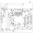
- FIG. 1 is a refrigerant circuit diagram showing a state of the air conditioner 1000 according to the first embodiment during full cooling operation.
- the air conditioner 1000 circulates a refrigerant in a refrigerant circuit and uses a refrigeration cycle to condition the air in a space to be air-conditioned.
- the air conditioner 1000 includes a heat source device 100, a plurality of indoor units 300a, 300b, and 300c, and a relay device 200.
- the air conditioner 1000 of this embodiment can perform cooling operation or heating operation for each of the plurality of indoor units 300a, 300b, and 300c.
- the air conditioner 1000 performs a full cooling operation in which a cooling operation is performed in all of the plurality of indoor units 300a, 300b, and 300c, and a full heating operation in which a heating operation is performed in all of the plurality of indoor units 300a, 300b, and 300c. is possible. Furthermore, the air conditioner 1000 according to the present embodiment is capable of performing simultaneous cooling and heating operations in which one of the plurality of indoor units 300a, 300b, and 300c performs a cooling operation, and one of the remaining indoor units performs a heating operation. be.
- simultaneous cooling and heating operations when the load of cooling operation is larger than the load of heating operation, it is called cooling-main operation, and when the load of heating operation is larger than the load of cooling operation, it is called heating-main operation.
- the number of heat source devices 100 and repeaters 200 may be two or more.
- the number of indoor units may be one, two, or four or more.
- the air conditioner 1000 is configured by connecting a heat source device 100, indoor units 300a to 300c, and a relay device 200.
- the heat source device 100 has a function of supplying heat to each of the indoor units 300a to 300c.
- the indoor units 300a to 300c are connected in parallel to the heat source device 100 and the relay device 200.
- the indoor units 300a to 300c have a function of cooling or heating a space to be air-conditioned, such as a room, using heat supplied from the heat source device 100.
- the relay device 200 is interposed between the heat source device 100 and the indoor units 300a to 300c, and switches the flow of refrigerant supplied from the heat source device 100 in response to a request from the indoor units 300a to 300c. It has the function of supplying
- the heat source device 100 and the relay device 200 are connected by a total of two refrigerant pipes, a gas main pipe 41 and a liquid main pipe 42, in a so-called liquid gas pipe connection manner.
- the gas main pipe 41 is a pipe through which gas refrigerant flows during both cooling operation and heating operation.
- the liquid main pipe 42 is a pipe through which liquid refrigerant or gas-liquid two-phase refrigerant flows during both cooling operation and heating operation.
- the repeater 200 and the indoor units 300a to 300c are each connected by a total of two refrigerant pipes. Specifically, the repeater 200 and the indoor unit 300a are connected through a gas branch pipe 43a and a liquid branch pipe 44a.
- the repeater 200 and the indoor unit 300b are connected by a gas branch pipe 43b and a liquid branch pipe 44b.
- the repeater 200 and the indoor unit 300c are connected by a gas branch pipe 43c and a liquid branch pipe 44c.
- Gaseous refrigerant mainly flows through the gas branch pipes 43a to 43c.
- a refrigerant mainly in a liquid state or a gas-liquid two-phase state flows through the liquid branch pipes 44a to 44c.
- the heat source device 100 includes a compressor 1 , a flow path switching valve 2 , a heat source side heat exchanger 3 , a heat source side flow control valve 4 , and a heat source device control device 5 .
- the compressor 1, the flow path switching valve 2, the heat source side heat exchanger 3, and the heat source side flow control valve 4 are connected by refrigerant piping shown in solid lines in FIG.
- the compressor 1 is a fluid machine that sucks in low-pressure gas refrigerant, compresses it, and discharges it as high-pressure gas refrigerant.
- the compressor 1 is, for example, an inverter-driven compressor whose operating frequency can be adjusted.
- the operating frequency or capacity of the compressor 1 is controlled by the heat source machine control device 5.
- the flow path switching valve 2 is a valve that switches the direction in which the refrigerant flows.
- the flow path switching valve 2 switches the direction in which the refrigerant discharged from the compressor 1 flows, depending on whether the full cooling operation, the main cooling operation, the full heating operation, or the main heating operation is performed.
- the flow path switching valve 2 is configured by a combination of a four-way valve, a two-way valve, a three-way valve, or the like. The operation of the flow path switching valve 2 is controlled by the heat source device control device 5.
- the heat source side heat exchanger 3 exchanges heat between the refrigerant flowing inside and another fluid.
- the heat source side heat exchanger 3 functions as an evaporator or a condenser.
- the heat source side heat exchanger 3 is, for example, an air-cooled heat exchanger, and exchanges heat with air from a blower disposed around the heat source side heat exchanger 3 and a refrigerant.
- the heat source side heat exchanger 3 may be a water-cooled heat exchanger that exchanges heat between water or brine and a refrigerant, for example.
- the heat source side flow control valve 4 is connected in series to the heat source side heat exchanger 3, and adjusts the flow rate of the refrigerant flowing through the refrigerant piping.
- the heat source side flow control valve 4 functions as a pressure reducing valve that reduces the pressure of the refrigerant and an expansion valve that expands the refrigerant.
- the heat source side flow control valve 4 is composed of, for example, an electric expansion valve whose opening degree can be adjusted. The operation of the heat source side flow control valve 4 is controlled by the heat source machine control device 5.
- the heat source device control device 5 controls the overall operation of the heat source device 100. Further, the heat source device control device 5 controls the operation of the entire air conditioner 1000 in cooperation with a repeater control device 201 and an indoor unit control device 33, which will be described later.
- the heat source device control device 5, the repeater control device 201, and the indoor unit control device 33 are connected to each other by a control line (not shown).
- the heat source equipment control device 5 is a computer, an ASIC (Application Specific Integrated Circuit), or an FPGA (Field Programmable Gate Array) that includes a memory that stores data and programs necessary for control, and a CPU (Central Processing Unit) that executes the programs. ), or both.
- the indoor unit 300a includes a load-side heat exchanger 31a, a load-side flow rate adjustment valve 32a, and an indoor unit control device 33a
- the indoor unit 300b includes a load-side heat exchanger 31b, a load-side flow rate adjustment valve 32b, and an indoor unit control device.
- the indoor unit 300c includes a load-side heat exchanger 31c, a load-side flow rate adjustment valve 32c, and an indoor unit control device 33c.
- the load side heat exchangers 31c to 31c will be referred to as the load side heat exchanger 31.
- the term "load-side heat exchanger 31" includes both singular and plural heat exchangers.
- the load side flow rate adjustment valves 32a to 32c will be referred to as load side flow rate adjustment valves 32.
- the term "load-side flow rate regulating valve 32" includes both singular and plural numbers.
- the indoor unit control devices 33a to 33c will be referred to as the indoor unit control device 33. When referring to the indoor unit control device 33, it shall include both the singular and plural.
- the load-side heat exchanger 31 exchanges heat between the refrigerant flowing inside and another fluid.
- the load side heat exchanger 31 functions as a condenser or an evaporator.
- the load-side heat exchanger 31 is, for example, an air-cooled heat exchanger, and exchanges heat with air from a blower disposed around the load-side heat exchanger 31 and a refrigerant.
- the load-side heat exchanger 31 may be a water-cooled heat exchanger that exchanges heat between water or brine and a refrigerant, for example.
- the load side flow rate adjustment valve 32 adjusts the flow rate of the refrigerant flowing into or out of the load side heat exchanger 31.
- the load side flow rate adjustment valve 32 functions as a pressure reducing valve that reduces the pressure of the refrigerant and an expansion valve that expands the refrigerant.
- the load-side flow rate adjustment valve 32 is composed of, for example, an electric expansion valve whose opening degree can be adjusted continuously or in multiple stages.
- the opening degree of the load side flow rate adjustment valve 32 is controlled by the indoor unit control device 33.
- the load side flow rate adjustment valve 32 is arranged upstream of the load side heat exchanger 31 in the flow direction of the refrigerant during full cooling operation.
- the indoor unit control device 33 controls the opening degree of the load-side flow rate adjustment valve 32 based on the control signal from the heat source device control device 5.
- the indoor unit control device 33 is composed of a computer including a CPU (Central Processing Unit) that executes a program, dedicated hardware such as an ASIC (Application Specific Integrated Circuit) or an FPGA (Field Programmable Gate Array), or both. be done.
- CPU Central Processing Unit
- ASIC Application Specific Integrated Circuit
- FPGA Field Programmable Gate Array
- the repeater 200 includes a repeater control device 201, a gas-liquid separator 202, and channel opening/closing devices 206a to 206c.
- the channel opening/closing devices 206a to 206c are provided in one-to-one correspondence with the indoor units 300a to 300c, and in this embodiment, a total of three channel opening/closing devices 206a to 206c are provided.
- the relay machine 200 of the present embodiment includes a first check valve 209, a second check valve 210, a check valve 211, a check valve 212, an on-off valve 213, and an on-off valve 214. ing.
- the relay device control device 201 controls the flow path opening/closing devices 206a to 206c, the first check valve 209, the second check valve 210, the check valve 211, and the check valve. 212, on-off valve 213, and on-off valve 214 are controlled.
- the repeater control device 201 is configured with a computer including a CPU (Central Processing Unit) that executes a program, dedicated hardware such as an ASIC (Application Specific Integrated Circuit) or an FPGA (Field Programmable Gate Array), or both. be done.
- CPU Central Processing Unit
- ASIC Application Specific Integrated Circuit
- FPGA Field Programmable Gate Array
- the gas-liquid separator 202 separates the refrigerant into gas refrigerant and liquid refrigerant.
- the gas-liquid separator 202 of this embodiment separates the high-pressure gas-liquid two-phase refrigerant generated by the heat source device 100 into liquid refrigerant and gas refrigerant when cooling-based operation is performed.
- the gas-liquid separator 202 is a container capable of storing a refrigerant, and has an inlet 203, a gas outlet 204, and a liquid outlet 205.
- the inlet 203 is connected to a pipe connected to the main liquid pipe 42 and allows the refrigerant that has flowed into the repeater 200 through the main liquid pipe 42 to flow into the gas-liquid separator 202 .
- the gas outlet 204 is provided above the gas-liquid separator 202 in the direction of gravity, and allows the gas refrigerant separated in the gas-liquid separator 202 to flow out from the gas-liquid separator 202 to the piping.
- the liquid outlet 205 is provided below the gas-liquid separator 202 in the direction of gravity, and allows the liquid refrigerant separated in the gas-liquid separator 202 to flow out from the gas-liquid separator 202 to the piping.
- the gas-liquid separator 202 is a container capable of storing a refrigerant
- a pipe may be used as the gas-liquid separator 202 instead of a container.
- the piping serving as the gas-liquid separator 202 may be branched to provide an inlet 203, a gas outlet 204, and a liquid outlet 205.
- the flow path opening/closing devices 206a to 206c are devices that open and close the refrigerant flow path from the heat source device 100 to the indoor units 300a to 300c and the refrigerant flow path from the indoor units 300a to 300c to the heat source device 100, respectively.
- the channel opening/closing device 206a includes a first valve 207a and a second valve 208a
- the channel opening/closing device 206b includes a first valve 207b and a second valve 208b
- the channel opening/closing device 206c includes a first valve 207c and a second valve 208b.
- a second valve 208c is provided.
- the channel opening/closing devices 206a to 206c when explaining matters common to the channel opening/closing devices 206a to 206c, the channel opening/closing devices 206a to 206c will be referred to as the channel opening/closing device 206.
- the first valves 207a to 207c when explaining matters common to the first valves 207a to 207c, the first valves 207a to 207c will be referred to as the first valve 207.
- the first valve 207 it shall include both the singular and the plural.
- the second valves 208a to 208c when describing matters common to the second valves 208a to 208c, the second valves 208a to 208c will be referred to as the second valve 208.
- Reference to the second valve 208 shall include both the singular and the plural.
- the flow path opening/closing device 206 has a first valve 207 and a second valve 208 connected in parallel to the indoor unit 300.
- the first valve 207 opens and closes the flow path between the first check valve 209 and the gas branch pipe 43.
- the first valve 207 is connected to a pipe that connects a pipe connected to the main gas pipe 41 and provided with the first check valve 209 and a pipe connected to the gas branch pipe 43. It is provided.
- the first valve 207 is an on-off valve that opens and closes a flow path for refrigerant flowing from the indoor unit 300 toward the heat source device 100.
- the second valve 208 opens and closes the flow path between the second check valve 210 and the gas branch pipe 43.
- the second valve 208 is provided in a pipe that connects the pipe connected to the main gas pipe 41 and provided with the second check valve 210 and the pipe connected to the gas branch pipe 43. .
- the second valve 208 is an on-off valve that opens and closes a flow path for refrigerant flowing from the heat source device 100 toward the indoor unit 300.
- the first valve 207 and the second valve 208 are, for example, electromagnetic valves or throttle valves with a fully closing function and adjustable opening, but the specific valve structure is not limited as long as it is possible to open and close the flow path. . When one of the first valve 207 and the second valve 208 is open, the other is closed, and both are never open.
- the first check valve 209 is provided in a pipe connected to the main gas pipe 41, allows the flow of refrigerant from the indoor unit 300 to the heat source device 100, and blocks the flow of refrigerant from the heat source device 100 to the indoor unit 300. do.
- the first check valve 209 prevents high-temperature and high-pressure gas refrigerant from flowing back from the flow path on the discharge side of the compressor 1 to the flow path opening/closing device 206 when full heating operation and heating-main operation are performed. This is to prevent
- the second check valve 210 is provided in a pipe connected to the main gas pipe 41 in parallel with the first check valve 209, and allows the refrigerant to flow from the heat source device 100 to the indoor unit 300. The flow of refrigerant to the heat source device 100 is cut off.
- the second backflow prevention valve 210 is configured so that when a cooling-only operation or a cooling-mainly operation is performed, refrigerant in a high-pressure liquid state or a gas-liquid two-phase state that has passed through the gas-liquid separator 202 is connected to the first backflow prevention valve 209 . This prevents the refrigerant from flowing back into the refrigerant pipe on the outlet side, that is, into the main gas pipe 41.
- the non-return valve 211 is provided in a pipe connecting the inlet side of the first non-return valve 209 and the main liquid pipe 42, and allows the refrigerant to flow from the indoor unit 300 to the heat source device 100. The flow of refrigerant to the indoor unit 300 is cut off.
- the check valve 211 prevents refrigerant in a high-pressure liquid state or a gas-liquid two-phase state from flowing into the outdoor unit 101 from the liquid main pipe 42 when all-cooling operation and cooling-mainly operation are performed. .
- the check valve 212 is provided in a pipe that connects the inlet 203 of the gas-liquid separator 202 and the main liquid pipe 42, and allows the refrigerant to flow from the heat source device 100 to the indoor unit 300. The flow of refrigerant to the heat source device 100 is cut off.
- the backflow prevention valve 212 prevents high-temperature, high-pressure gas refrigerant from flowing into the heat source side heat exchanger 3 when the heating-only operation and the heating-main operation are performed.
- the on-off valve 213 is provided in the pipe 241 connected to the liquid outlet 205 of the gas-liquid separator 202, and opens and closes the refrigerant flow path.
- the on-off valve 213 is, for example, a solenoid valve.
- the on-off valve 214 is provided in a pipe through which the liquid refrigerant flowing out from the liquid branch pipe 44 flows when the heating-only operation or the heating-main operation is performed, and opens and closes the flow path of the refrigerant.
- an on-off valve 214 is provided in a pipe 240 that connects the inlet side of the first check valve 209 and the liquid branch pipe 44 .
- the pipe 240 is a single pipe that is connected to the plurality of liquid branch pipes 44 via a pipe 243 and a pipe 244.
- Piping 240 and piping 241 intersect at intersection 242.
- the refrigerant in the pipe 240 and the refrigerant in the pipe 241 flow together or diverge at the intersection 242 depending on the open/close states of the on-off valve 213 and the on-off valve 214.
- the operations of the second valve 208 and the first valve 207, the first check valve 209, the second check valve 210, the check valve 211, the check valve 212, the on-off valve 213, and the on-off valve 214 of the flow path opening/closing device 206 are as follows. , is controlled by the repeater control device 201.
- the pipe connected to the main gas pipe 41 is branched into two, one pipe is provided with a first check valve 209, and the other pipe is provided with a second check valve 210.
- a pipe connected to the check valve 211 and a pipe connected to the first valve 207 are connected to the pipe 240 on the inlet side of the first check valve 209 to which the first check valve 209 is connected.
- On the outflow side of the second check valve 210 of the pipe to which the second check valve 210 is connected there is a pipe 245 connected to the gas outlet 204 of the gas-liquid separator 202, a pipe connected to the second valve 208, is connected.
- Piping 240 and piping 241 intersect at intersection 242, and further branch into piping 243 and piping 244. All the liquid branch pipes 44 are connected to the pipe 243, and all the liquid branch pipes 44 are also connected to the pipe 244.
- refrigerant In the air conditioner 1000, refrigerant is filled inside the piping.
- Refrigerants include, but are not particularly limited to, natural refrigerants such as carbon dioxide, hydrocarbons, and helium, chlorine-free fluorocarbon alternative refrigerants such as HFC410A, HFC407C, and HFC404A, or fluorocarbons used in existing products such as R22 and R134a. system refrigerant, etc.
- FIGS. 1 to 4 The operation of air conditioner 1000 will be explained with reference to FIGS. 1 to 4.
- the flow of refrigerant is indicated by arrows.
- the on-off valves shown in FIGS. 1 to 4 the on-off valves through which refrigerant does not flow are shown in black.
- a low-temperature, low-pressure refrigerant is sucked into the compressor 1, compressed, and discharged from the compressor 1 as a high-temperature, high-pressure gas refrigerant.
- the high-temperature, high-pressure gas refrigerant discharged from the compressor 1 passes through the flow path switching valve 2 and is condensed and liquefied by exchanging heat with a fluid such as air in the heat source side heat exchanger 3 that functions as a condenser or a radiator.
- the high-pressure liquid refrigerant then passes through the heat source side flow control valve 4, flows through the liquid main pipe 42, and flows into the repeater 200.
- the refrigerant that has flowed into the relay machine 200 passes through the check valve 212 and reaches the inside of the gas-liquid separator 202 from the inlet 203.
- the high-pressure liquid refrigerant that has flowed into the gas-liquid separator 202 flows out from the liquid outlet 205 and passes through the open/close valve 213 provided in the pipe 241 .
- the refrigerant flowing through the pipe 241 passes through the pipe 243 and the pipe 244, and branches into each of the liquid branch pipes 44a to 44c.
- the refrigerant flowing through each of the liquid branch pipes 44a to 44c flows into each of the indoor units 300a to 300c.
- the refrigerant that has flowed into the indoor units 300a to 300c is reduced in pressure by the load side flow rate adjustment valves 32a to 32c, respectively.
- the refrigerant which has been reduced in pressure and has become a low-temperature, low-pressure gas-liquid two-phase state, flows into the load-side heat exchangers 31a to 31c, which function as evaporators, and exchanges heat with indoor air in the load-side heat exchangers 31a to 31c. Evaporates into gas.
- the air-conditioned space such as the indoor space in which the indoor units 300a to 300c are installed, is cooled.
- the refrigerant which has become a low-temperature, low-pressure gas, flows into the channel opening/closing devices 206a to 206c of the repeater 200 through the gas branch pipes 43a to 43c, respectively.
- the first valves 207a to 207c are in an open state, and the second valves 208a to 208c are in a closed state.
- the refrigerant that has flowed into each of the channel opening/closing devices 206a to 206c passes through each of the first valves 207a to 207c, further passes through the first check valve 209, and flows out from the repeater 200.
- the gas refrigerant flowing out from the relay device 200 flows into the heat source device 100 through the gas main pipe 41.
- the refrigerant that has flowed into the heat source device 100 passes through the flow path switching valve 2 and is sucked into the compressor 1 .
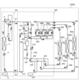
- FIG. 2 is a refrigerant circuit diagram showing a state in which the air conditioner 1000 according to the first embodiment is operating mainly for cooling.
- the indoor unit 300a performs a heating operation
- the indoor units 300b and 300c perform a cooling operation.
- the load for cooling operation is for two indoor units 300b and 300c, while the load for heating operation is for one indoor unit 300a, so the load for cooling operation is greater than the load for heating operation. It's also big.
- the refrigerant flow path of the flow path switching valve 2 is set such that the discharge side of the compressor 1 is connected to the heat source side heat exchanger 3.
- a low-temperature, low-pressure refrigerant is sucked into the compressor 1, compressed, and discharged from the compressor 1 as a high-temperature, high-pressure gas refrigerant.
- the high-temperature, high-pressure gas refrigerant discharged from the compressor 1 passes through the flow path switching valve 2 and exchanges heat with a fluid such as air in the heat source side heat exchanger 3 that functions as a condenser or radiator to form a gas-liquid two-phase gas refrigerant. become a state.
- the high-pressure gas-liquid two-phase refrigerant then passes through the heat source side flow control valve 4, flows through the liquid main pipe 42, and flows into the repeater 200.
- the refrigerant that has flowed into the relay machine 200 passes through the check valve 212 and reaches the inside of the gas-liquid separator 202 from the inlet 203.
- the gas-liquid separator 202 the gas-liquid two-phase refrigerant is separated into a gaseous refrigerant and a liquid refrigerant.
- the gaseous refrigerant flowing out from the gas outlet 204 of the gas-liquid separator 202 passes through the second valve 208a and flows into the indoor unit 300a through the gas branch pipe 43a.
- the refrigerant that has flowed into the indoor unit 300a exchanges heat with indoor air in the load-side heat exchanger 31a, which functions as a condenser or a radiator, and is condensed and liquefied.
- the air-conditioned space such as the indoor space in which the indoor unit 300a is installed, is heated.
- the high-pressure liquid refrigerant flows out of the load-side heat exchanger 31a and passes through the load-side flow rate adjustment valve 32a.
- the load side flow rate adjustment valve 32a Although the load side flow rate adjustment valve 32a is in a fully open state, the refrigerant is slightly depressurized when passing through the load side flow rate adjustment valve 32a.
- the refrigerant that has passed through the load-side flow rate adjustment valve 32a flows into the repeater 200 through the liquid branch pipe 44a, and flows through the pipes 243 and 244.
- the liquid refrigerant flowing out from the liquid outlet 205 of the gas-liquid separator 202 passes through the open on-off valve 213 provided in the pipe 241, passes through the intersection 242, and flows into the pipes 243 and 244.
- the liquid refrigerant from the liquid branch pipe 44a and the liquid refrigerant from the pipe 241 join together, and this liquid refrigerant flows into the indoor unit 300b or 300c through the liquid branch pipe 44b or 44c. .
- the refrigerant that has flowed into the indoor unit 300b or 300c is reduced in pressure by the load-side flow rate adjustment valve 32b or 32c, respectively, and enters a gas-liquid two-phase state.
- the decompressed gas-liquid two-phase refrigerant flows into the load-side heat exchanger 31b or 31c functioning as an evaporator, exchanges heat with indoor air in the load-side heat exchanger 31b or 31c, and evaporates into gas.
- the air-conditioned space such as the indoor space where the indoor units 300b and 300c are installed, is cooled.
- the refrigerant in a low-temperature, low-pressure gas state flows into the channel opening/closing device 206b or 206c of the repeater 200 through the gas branch pipe 43b or 43c, respectively.
- the amount of refrigerant flowing into the indoor unit 300 performing the cooling operation and the amount of refrigerant flowing into the indoor unit 300 performing the heating operation can be adjusted by adjusting the amount of heat exchange in the heat source side heat exchanger 3. Realized.
- the capacity of the compressor 1 is increased and the amount of gas refrigerant flowing out from the heat source side heat exchanger 3 increases, and the amount of gas refrigerant flowing out from the gas-liquid separator 202 is increased.
- the amount of gas refrigerant flowing into the machine 300 also increases.
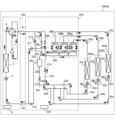
- FIG. 3 is a refrigerant circuit diagram showing a state of the air conditioner 1000 according to the first embodiment during full heating operation.
- all indoor units 300a to 300c perform heating operation.
- the refrigerant flow path of the flow path switching valve 2 is set such that the discharge side of the compressor 1 is connected to the main gas pipe 41 .
- a low-temperature, low-pressure refrigerant is sucked into the compressor 1, compressed, and discharged from the compressor 1 as a high-temperature, high-pressure gas refrigerant.
- the high-temperature, high-pressure gas refrigerant discharged from the compressor 1 passes through the flow path switching valve 2, flows through the gas main pipe 41, and flows into the repeater 200.
- the high-temperature, high-pressure gas refrigerant that has flowed into the repeater 200 passes through the second check valve 210 and flows into each of the channel opening/closing devices 206a to 206c.
- the second valves 208a to 208c are in an open state
- the first valves 207a to 207c are in a closed state.
- the refrigerant that has flowed into each of the flow path opening/closing devices 206a to 206c passes through each of the second valves 208a to 208c, further passes through each of the gas branch pipes 43a to 43c, and flows into each of the indoor units 300a to 300c. do.
- the gas refrigerant that has flowed into each of the indoor units 300a to 300c exchanges heat with indoor air in the load side heat exchangers 31a to 31c, which function as condensers or radiators, and is condensed and liquefied.
- the air-conditioned space such as the indoor space in which the indoor units 300a to 300c are installed, is heated.
- the pressure of the liquid refrigerant flowing out from each of the indoor units 300a to 300c is reduced by each of the load side flow rate adjustment valves 32a to 32c.
- the low-pressure liquid refrigerant then flows into the repeater 200 through each of the liquid branch pipes 44a to 44c.
- the downstream side of the on-off valve 214 and the downstream side of the first check valve 209 communicate with each other, but the first valve that communicates with the discharge side of the compressor 1 While the downstream side of the check valve 209 has a high pressure, the refrigerant flowing through the on-off valve 214 has a low pressure. Therefore, other refrigerant flowing through the on-off valve 214 does not pass through the first check valve 209 . Then, the low-pressure liquid refrigerant passes through the on-off valve 214 in the open state and the check valve 211, and flows out from the relay machine 200.
- the liquid refrigerant flowing out from the relay machine 200 flows into the heat source machine 100 through the liquid main pipe 42.
- the refrigerant that has flowed into the heat source device 100 passes through the heat source side flow control valve 4 and flows into the heat source side heat exchanger 3 that functions as an evaporator.
- the low-pressure liquid refrigerant exchanges heat with a fluid such as air in the heat source side heat exchanger 3, absorbs heat, and evaporates into gas.
- the low-pressure gas refrigerant that has flowed out of the heat source side heat exchanger 3 passes through the flow path switching valve 2 and is sucked into the compressor 1 .
- FIG. 4 is a refrigerant circuit diagram showing a state of the air conditioner 1000 according to the first embodiment when the air conditioner 1000 is mainly operated for heating.
- the indoor unit 300a performs a cooling operation
- the indoor units 300b and 300c perform a heating operation.
- the load for heating operation is for two indoor units 300b and 300c, while the load for cooling operation is for one indoor unit 300a, so the load for heating operation is greater than the load for cooling operation. It's also big.
- the refrigerant flow path of the flow path switching valve 2 is set such that the discharge side of the compressor 1 is connected to the main gas pipe 41 .
- a low-temperature, low-pressure refrigerant is sucked into the compressor 1, compressed, and discharged from the compressor 1 as a high-temperature, high-pressure gas refrigerant.
- the high-temperature, high-pressure gas refrigerant discharged from the compressor 1 passes through the flow path switching valve 2, flows through the gas main pipe 41, and flows into the repeater 200.
- the high-temperature, high-pressure gas refrigerant that has flowed into the repeater 200 passes through the second check valve 210 and flows into each of the channel opening/closing devices 206a to 206c.
- the second valves 208b and 208c are in an open state, and the second valve 208a is in a closed state.
- the first valve 207a is in an open state, and the first valves 207b and 207c are in a closed state.
- the gas refrigerant that has flowed into the channel opening/closing device 206b or 206c passes through the second valve 208b or 208c, respectively, and flows into the indoor unit 300b or 300c through the gas branch pipe 43b or 43c.
- the high-pressure gas refrigerant that has flowed into the indoor unit 300b or 300c exchanges heat with indoor air in the load-side heat exchanger 31b or 31c, which functions as a condenser or a radiator, respectively, and is condensed and liquefied. At that time, an air-conditioned space such as an indoor space in which the indoor unit 300b or 300c is installed is heated.
- the high-pressure liquid refrigerant flows out from the load-side heat exchanger 31b or 31c, and is reduced in pressure to a low pressure by the load-side flow rate adjustment valve 32b or 32c, respectively, and becomes a low-temperature, low-pressure gas-liquid two-phase refrigerant.
- the gas-liquid two-phase refrigerant that has passed through the load-side flow rate adjustment valve 32b or 32c passes through the liquid branch pipe 44b or 44c, flows into the repeater 200, and flows through the pipe 243 or 244.
- gas-liquid two-phase refrigerant that has flowed into the pipe 243 or the pipe 244 flows into the indoor unit 300a through the liquid branch pipe 44a, and the remaining refrigerant flows through the pipe 240 from the intersection 242 and continues into the open state. It passes through the on-off valve 214.
- the gas-liquid two-phase refrigerant that has flowed into the indoor unit 300a is depressurized at the load-side flow rate adjustment valve 32a, exchanges heat with indoor air at the load-side heat exchanger 31a that functions as an evaporator, and is evaporated into gas. .
- the air-conditioned space such as the indoor space in which the indoor unit 300a is installed, is cooled.
- the gas refrigerant flowing out from the load-side heat exchanger 31a flows into the channel opening/closing device 206a through the gas branch pipe 43a.
- the gas refrigerant that has flowed into the flow path opening/closing device 206a passes through the first valve 207a, merges with the gas-liquid two-phase refrigerant that has passed through the opening/closing valve 214, and passes through the backflow prevention valve 211 as a gas-liquid two-phase refrigerant. pass through.
- the gas-liquid two-phase refrigerant that has passed through the check valve 211 flows out from the repeater 200 .
- the gas-liquid two-phase refrigerant flowing out from the relay machine 200 flows into the heat source machine 100 through the liquid main pipe 42.
- the refrigerant that has flowed into the heat source device 100 passes through the heat source side flow control valve 4 and flows into the heat source side heat exchanger 3 that functions as an evaporator.
- the refrigerant flowing into the heat source side heat exchanger 3 exchanges heat with a fluid such as air in the heat source side heat exchanger 3, absorbs heat, and becomes a low temperature, low pressure gas refrigerant.
- the low-temperature, low-pressure gas refrigerant that has flowed out of the heat source side heat exchanger 3 is sucked into the compressor 1 through the flow path switching valve 2 .
- high-temperature, high-pressure gas refrigerant is sent to the relay device 200 from one of the indoor units 300a to 300c without passing through the gas-liquid separator 202.
- a path for the refrigerant to flow into is formed. Since the gas refrigerant does not pass through the gas-liquid separator 202, no pressure loss of the gas refrigerant occurs in the gas-liquid separator 202. Therefore, a decrease in the performance of the air conditioner 1000 due to the pressure loss of the refrigerant in the gas-liquid separator 202 can be avoided.
- the air conditioner 1000 of the present embodiment includes a heat source device 100 having a compressor 1, a flow path switching valve 2, and a heat source side heat exchanger 3, one or more indoor units 300, and a relay device 200. Equipped with.
- One or more indoor units 300 have a load-side flow rate adjustment valve 32 and a load-side heat exchanger 31, and perform cooling operation or heating operation.
- the relay device 200 is connected to the heat source device 100 by a gas main pipe 41 through which a gas refrigerant flows during cooling and heating operations, and a liquid main pipe 42 through which a liquid refrigerant or a gas-liquid two-phase refrigerant flows during cooling and heating operations.
- the relay device 200 is connected to the indoor unit 300 through a gas branch pipe 43 and a liquid branch pipe 44, and supplies the indoor unit 300 with the refrigerant supplied from the heat source device 100. Furthermore, the relay device 200 includes a gas-liquid separator 202 that separates the refrigerant into a gas refrigerant and a liquid refrigerant, a refrigerant flow path from the heat source device 100 to the indoor unit 300, and a refrigerant flow path from the indoor unit 300 to the heat source device 100. It includes one or more channel opening/closing devices 206 that open and close the channels, respectively.
- the refrigerant that has flowed into the relay device 200 from the heat source device 100 through the gas main pipe 41 is stored in the relay device 200 without passing through the gas-liquid separator 202. It has a path for the refrigerant to flow into the channel opening/closing device 206.
- the air conditioner 1000 of this embodiment when the heating operation is performed, the high temperature and high pressure gas refrigerant flows into the indoor unit 300 without passing through the gas-liquid separator 202. Since the gas refrigerant does not pass through the gas-liquid separator 202, no pressure loss of the gas refrigerant occurs in the gas-liquid separator 202. Therefore, a decrease in the performance of the air conditioner 1000 due to the pressure loss of the refrigerant in the gas-liquid separator 202 can be avoided.
- the one or more indoor units 300 are a plurality of indoor units 300a to 300c
- the flow path opening/closing device 206 is a plurality of flow paths that are the same number as the plurality of indoor units 300.
- These are opening/closing devices 206a to 206c.
- the plurality of airflows are arranged so that the cooling operation by one or more of the plurality of indoor units 300a to 300c and the heating operation by one or more of the other one or more of the plurality of indoor units 300a to 300c are performed simultaneously.
- the road switching devices 206a to 206c are controlled.
- the relay device 200 of the air conditioner 1000 of the present embodiment is provided in a pipe connected to the gas main pipe 41, allows the refrigerant to flow from the indoor unit 300 to the heat source device 100, and allows the refrigerant to flow from the indoor unit 300 to the heat source device 100.
- a first check valve 209 that blocks the flow of refrigerant to the machine 300 is provided.
- the relay device 200 is provided in parallel with the first check valve 209 in a pipe connected to the gas main pipe 41, and allows the flow of refrigerant from the heat source device 100 to the indoor unit 300, and allows the refrigerant to flow from the indoor unit 300 to the heat source device.
- a second check valve 210 that blocks the flow of refrigerant to 100 is provided.
- the refrigerant outlet of the second check valve 210 is connected to the piping connecting each of the plurality of flow path opening/closing devices 206a to 206c and the gas outlet 204 from which the gas refrigerant of the gas-liquid separator 202 flows out.
- a pipe 245 is connected thereto.
- the air conditioner 1000 of this embodiment includes the first check valve 209 as described above. Therefore, it is possible to prevent high-temperature and high-pressure gas refrigerant from flowing back from the flow path on the discharge side of the compressor 1 to the flow path opening/closing device 206 when the heating-only operation or the heating-based operation is performed. can.
- the air conditioner 1000 of the embodiment includes the second check valve 210 as described above. Therefore, even if the refrigerant in the high-pressure liquid state or gas-liquid two-phase state that has passed through the gas-liquid separator 202 flows into the pipe 245 when the cooling-only operation or the cooling-mainly operation is performed, the second backflow prevention The valve 210 blocks the flow. This prevents the high-pressure liquid or gas-liquid two-phase refrigerant that has passed through the gas-liquid separator 202 from flowing back into the refrigerant pipe on the outlet side of the first check valve 209, that is, into the main gas pipe 41. can do.
- Embodiment 2 a configuration including a pressure relief valve 215 in addition to the circuit configuration shown in Embodiment 1 will be described. In this embodiment, differences from Embodiment 1 will be mainly described, and descriptions of matters common to Embodiment 1 will be omitted as appropriate.
- FIG. 5 is a refrigerant circuit diagram showing the state of the air conditioner 1000A according to the second embodiment during full cooling operation.
- the air conditioner 1000A includes a pressure relief valve provided in the pipe connecting the pipe connected to the gas outlet 204 of the gas-liquid separator 202 and the pipe connected to the main gas pipe 41 in the repeater 200. It is equipped with 215.
- the pressure relief valve 215 is an on-off valve whose open/close state is controlled by the repeater control device 201.
- Pressure relief valve 215 is connected to piping 250, which is a high pressure line connected to second valves 208a-208c.
- the pressure relief valve 215 becomes open when the pressure of the refrigerant in the pipe 250 connecting the gas-liquid separator 202 and the second valves 208a to 208c becomes equal to or higher than the saturation pressure of the refrigerant.
- the pressure relief valve 215 is closed when the pressure of the refrigerant in the pipe 250 is less than the saturation pressure of the refrigerant.
- the open/close state of the pressure relief valve 215 is controlled by the repeater control device 201.
- FIGS. 5 to 8 The operation of the air conditioner 1000A will be explained with reference to FIGS. 5 to 8.
- the flow of refrigerant is indicated by arrows.
- the on-off valves shown in FIGS. 5 to 8 the on-off valves through which refrigerant does not flow are shown in black.
- FIG. 5 is a refrigerant circuit diagram showing a state of full cooling operation of the air conditioner 1000A according to the second embodiment.
- the pressure relief valve 215 operates as follows in the full cooling operation. That is, the pressure relief valve 215 becomes open when the pressure of the refrigerant in the pipe 250 connecting the gas-liquid separator 202 and the second valves 208a to 208c becomes equal to or higher than the saturation pressure of the refrigerant.
- the pressure relief valve 215 is closed when the pressure of the refrigerant in the pipe 250 is less than the saturation pressure of the refrigerant.
- the pressure relief valve 215 is set to the open state when the pressure of the piping 250, which is a high pressure line, becomes equal to or higher than the saturation pressure of the refrigerant. Established. Therefore, the refrigerant circuit of the air conditioner 1000A does not exceed the saturation pressure of the refrigerant. Therefore, the safety of the air conditioner 1000A can be improved.
- the pressure relief valve 215 may be periodically opened. By doing so, the refrigerant circuit of the air conditioner 1000A does not exceed the saturation pressure of the refrigerant. Therefore, the safety of the air conditioner 1000A can be improved.
- FIG. 6 is a refrigerant circuit diagram showing a state in which the air conditioner 1000A according to the second embodiment is mainly operated for cooling.
- indoor unit 300a performs heating operation
- indoor units 300b and 300c perform cooling operation.
- the load for cooling operation is for two indoor units 300b and 300c, while the load for heating operation is for one indoor unit 300a, so the load for cooling operation is greater than the load for heating operation. It's also big.
- the pressure relief valve 215 operates as follows. That is, the pressure relief valve 215 becomes open when the pressure of the refrigerant in the pipe 250 connecting the gas-liquid separator 202 and the second valves 208a to 208c becomes equal to or higher than the saturation pressure of the refrigerant. The pressure relief valve 215 is closed when the pressure of the refrigerant in the pipe 250 is less than the saturation pressure of the refrigerant.
- the pressure relief valve 215 is set to open when the pressure of the piping 250, which is a high pressure line, becomes equal to or higher than the saturation pressure of the refrigerant when the cooling-based operation is performed.
- the refrigerant circuit of the air conditioner 1000A does not exceed the saturation pressure of the refrigerant. Therefore, the safety of the air conditioner 1000A can be improved.
- FIG. 7 is a refrigerant circuit diagram showing a state of full heating operation of the air conditioner 1000A according to the second embodiment.
- all indoor units 300a to 300c perform heating operation.
- Air conditioner 1000A shown in FIG. 7 performs the operation shown in Embodiment 1 in full heating operation.
- the pressure relief valve 215 of the repeater 200 is always in a fully closed state.
- FIG. 8 is a refrigerant circuit diagram showing a state of the air conditioner 1000A according to the second embodiment when the air conditioner 1000A is mainly operating for heating.
- the indoor unit 300a performs a cooling operation
- the indoor units 300b and 300c perform a heating operation.
- Air conditioner 1000A shown in FIG. 8 performs the operation shown in Embodiment 1 in heating-based operation.
- the pressure relief valve 215 of the repeater 200 is always in a fully closed state.
- the air conditioner 1000A of this embodiment includes the pressure relief valve 215 provided in the pipe that communicates the main gas pipe 41 with the gas outlet 204 of the gas-liquid separator 202.
- the pressure relief valve 215 is connected to each of the flow path opening/closing devices 206a to 206c and the gas outlet 204 through which the gas refrigerant of the gas-liquid separator 202 flows out when one or more of the plurality of indoor units 300 is performing cooling operation.
- the refrigerant pressure in the pipe 250 connecting the refrigerant becomes equal to or higher than the saturation pressure of the refrigerant, the open state is established. Therefore, the refrigerant circuit of the air conditioner 1000A does not exceed the saturation pressure of the refrigerant. Therefore, the safety of the air conditioner 1000A can be improved.
- the pressure relief valve 215 of the air conditioner 1000A allows the gas refrigerant from each of the plurality of channel opening/closing devices 206a to 206c and the gas-liquid separator 202 to flow out when the cooling-only operation or the cooling-mainly operation is performed.
- the pressure of the refrigerant in the pipe connecting to the gas outlet 204 is less than the saturation pressure of the refrigerant, it may be periodically opened. By doing so, the refrigerant circuit of the air conditioner 1000A does not exceed the saturation pressure of the refrigerant. Therefore, the safety of the air conditioner 1000A can be improved.
- Embodiment 3 an air conditioner 1000B including a channel opening/closing device 223 different from those in Embodiments 1 and 2 will be described.
- the air conditioner 1000B of this embodiment further includes a refrigerant heat exchanger 226.
- differences from Embodiments 1 and 2 will be mainly described, and descriptions of matters common to Embodiments 1 and 2 will be omitted as appropriate.
- FIG. 9 is a refrigerant circuit diagram showing a state of the air conditioner 1000B according to the third embodiment during full cooling operation.
- the air conditioner 1000B is configured by connecting a heat source device 100, indoor units 300a to 300c, and a relay device 200.
- the heat source device 100 has a function of supplying heat to each of the indoor units 300a to 300c.
- Indoor units 300a to 300c are connected in parallel to each other.
- the indoor units 300a to 300c have a function of cooling or heating a space to be air-conditioned, such as a room, using heat supplied from the heat source device 100.
- the relay device 200 is interposed between the heat source device 100 and the indoor units 300a to 300c, and switches the flow of refrigerant supplied from the heat source device 100 in response to a request from the indoor units 300a to 300c. It has the function of supplying
- the heat source device 100 and the relay device 200 are connected by a total of two refrigerant pipes, a gas main pipe 41 and a liquid main pipe 42, in a so-called liquid gas pipe connection manner.
- the gas main pipe 41 is a pipe through which gas refrigerant flows during both cooling operation and heating operation.
- the liquid main pipe 42 is a pipe through which liquid refrigerant or gas-liquid two-phase refrigerant flows during both cooling operation and heating operation.
- the repeater 200 and the indoor units 300a to 300c are each connected by a total of two refrigerant pipes. Specifically, the repeater 200 and the indoor unit 300a are connected through a gas branch pipe 43a and a liquid branch pipe 44a.
- the repeater 200 and the indoor unit 300b are connected by a gas branch pipe 43b and a liquid branch pipe 44b.
- the repeater 200 and the indoor unit 300c are connected by a gas branch pipe 43c and a liquid branch pipe 44c.
- Gaseous refrigerant mainly flows through the gas branch pipes 43a to 43c.
- a refrigerant mainly in a liquid state or a gas-liquid two-phase state flows through the liquid branch pipes 44a to 44c.
- the configurations of the heat source device 100 and the indoor unit 300 are the same as in the first and second embodiments.
- the repeater 200 includes a repeater control device 201, a gas-liquid separator 202, and channel opening/closing devices 223a to 223c.
- the channel opening/closing devices 223a to 223c are provided in one-to-one correspondence with the indoor units 300a to 300c, and in this embodiment, a total of three channel opening/closing devices 223a to 223c are provided.
- the repeater 200 of this embodiment includes a low pressure pipe 220, a high pressure pipe 221, folded pipes 222a and 222b, a refrigerant heat exchanger 226, a first check valve 229, and a second check valve 230. and a third check valve 231.
- the low pressure pipe 220 is a pipe connected to a pipe connected to the main gas pipe 41 via a first check valve 229 .
- the low pressure pipe 220 is connected to each of the indoor units 300a to 300c via first valves 224a to 224b provided in each of the channel opening/closing devices 223a to 223c.
- the high-pressure pipe 221 is a pipe connected to a pipe connected to the main gas pipe 41 via a second check valve 230.
- the high pressure pipe 221 is connected to each of the indoor units 300a to 300c via second valves 225a to 225b provided in each of the channel opening/closing devices 223a to 223c.
- the folded pipes 222a and 222b are pipes connected to each of the indoor units 300a to 300c.
- the folded pipe 222a is connected to each of the liquid branch pipes 44a to 44c via the first indoor unit non-return valves 236a to 236c, respectively.
- the first backflow prevention valves 236a to 236c for indoor units allow the refrigerant to flow from the folded tube 222a to each of the indoor units 300a to 300c, and block the flow of refrigerant in the opposite direction.
- the folded tube 222a is connected to a folded tube 222b and a refrigerant heat exchanger 226 via piping.
- the folded pipe 222b is connected to each of the liquid branch pipes 44a to 44c via second check valves for indoor units 237a to 237c, respectively.
- the second backflow prevention valves 237a to 237c for indoor units allow the flow of refrigerant from each of the indoor units 300a to 300c to the folded tube 222b, and block the flow of refrigerant in the opposite direction.
- the first check valve 229 is provided in a pipe connected to the main gas pipe 41, allows the flow of refrigerant from the indoor unit 300 to the heat source device 100, and blocks the flow of refrigerant from the heat source device 100 to the indoor unit 300. do.
- the first check valve 229 prevents high-temperature and high-pressure gas refrigerant from flowing back from the flow path on the discharge side of the compressor 1 to the flow path opening/closing device 206 when full heating operation and heating-main operation are performed. This is to prevent
- the second check valve 230 is provided in a pipe connected to the main gas pipe 41 in parallel with the first check valve 229, and allows the refrigerant to flow from the heat source device 100 to the indoor unit 300. The flow of refrigerant to the heat source device 100 is cut off.
- the second backflow prevention valve 230 is configured such that when a cooling-only operation or a cooling-mainly operation is performed, the refrigerant in a high-pressure liquid state or a gas-liquid two-phase state that has passed through the gas-liquid separator 202 flows through the first backflow prevention valve 229. This prevents the refrigerant from flowing back into the refrigerant pipe on the outlet side, that is, into the main gas pipe 41.
- the flow path opening/closing devices 223a to 223c are devices that open and close the refrigerant flow path from the heat source device 100 to the indoor units 300a to 300c and the refrigerant flow path from the indoor units 300a to 300c to the heat source device 100, respectively.
- the channel opening/closing device 223a includes a first valve 224a and a second valve 225a
- the channel opening/closing device 223b includes a first valve 224b and a second valve 225b
- the channel opening/closing device 223c includes a first valve 224c and a second valve 225b.
- a second valve 225c is provided.
- the channel opening/closing devices 223a to 223c will be referred to as the channel opening/closing device 223.
- the first valves 224a to 224c will be referred to as the first valve 224.
- the second valves 225a to 225c will be referred to as second valves 225.
- the second valve 225 it shall include both the singular and the plural.
- the flow path opening/closing device 223 has a first valve 224 and a second valve 225 connected in parallel to the indoor unit 300.
- the first valve 224 is connected to the low pressure pipe 220.
- the first valve 224 opens and closes the flow path between the first check valve 229 and the gas branch pipe 43.
- the first valve 224 is an on-off valve that opens and closes a flow path for refrigerant flowing from the indoor unit 300 toward the heat source device 100.
- the second valve 225 is connected to the high pressure pipe 221.
- the second valve 225 opens and closes the flow path between the second check valve 230 and the gas branch pipe 43.
- the second valve 225 is an on-off valve that opens and closes a flow path for refrigerant flowing from the heat source device 100 toward the indoor unit 300.
- the first valve 224 and the second valve 225 are, for example, electromagnetic valves or throttle valves that have a fully closing function and whose opening can be adjusted, but the specific structure of the valves is not limited as long as it is possible to open and close the flow path. .
- the first valve 224 and the second valve 225 When one of the first valve 224 and the second valve 225 is open, the other is closed, and both are never open.
- the refrigerant heat exchanger 226 exchanges heat between the refrigerant flowing inside the repeater 200 and the refrigerant.
- the refrigerant heat exchanger 226 is provided in a pipe that connects the liquid outlet 205 of the gas-liquid separator 202 and the folded tubes 222a and 222b.
- a branch pipe 227 branches off from a branch portion 228 between the refrigerant heat exchanger 226 and the folded tubes 222a and 222b, and serves as a flow path for the refrigerant of the refrigerant heat exchanger 226.
- a third on-off valve 234 is provided in the branch pipe 227 between the branch portion 228 and the refrigerant heat exchanger 226 .
- a branch pipe 227 exiting the refrigerant heat exchanger 226 is connected to a high pressure pipe 221. Specifically, the end of the branch pipe 227 is connected to the high pressure pipe 221 on the outlet side of the second check valve 230 .
- a pipe 262 branches from between the connection portion between the refrigerant heat exchanger 226 and the high-pressure pipe 221 .
- the pipe 262 is connected to a pipe that connects the low pressure pipe 220 and the first check valve 229 .
- heat exchange is performed between the refrigerant flowing through the pipe 260 and the refrigerant flowing through the branch pipe 227 .
- the third on-off valve 234 is composed of, for example, an electric expansion valve whose opening degree can be adjusted.
- the operation of the third on-off valve 234 is controlled by the repeater control device 201.
- a first on-off valve 232 is provided in a pipe 260 that connects the folded pipes 222a and 222b and the liquid main pipe 42 via the gas-liquid separator 202 and the refrigerant heat exchanger 226.
- the first on-off valve 232 opens and closes the refrigerant flow path in the pipe 260.
- the first on-off valve 232 is composed of, for example, an electric expansion valve whose opening degree can be adjusted. The operation of the first on-off valve 232 is controlled by the repeater control device 201.
- a portion of the branch pipe 227 between the position where the pipe 262 branches from the branch pipe 227 and the end connected to the high pressure pipe 221 is referred to as a pipe 261.
- a third check valve 231 is provided in the pipe 261 .
- the third check valve 231 allows the refrigerant to flow from the branch pipe 227 of the refrigerant heat exchanger 226 to the high-pressure pipe 221, and blocks the refrigerant from flowing in the opposite direction.
- the piping 262 is provided with an on-off valve 235 for controlling valve pressure.
- an on-off valve 235 for controlling valve pressure.
- high-pressure refrigerant that is about to flow into the indoor unit 300 pushes the closed third on-off valve 234 and passes through it, and can flow into the high-pressure pipe 221 through the pipe 261.
- the refrigerant that has flowed into the high-pressure pipe 221 may lose its flow direction due to the second check valve 230, increase in pressure, and exceed the condensation pressure, thereby becoming liquid refrigerant. Therefore, a valve pressure control on-off valve 235 is provided in a pipe 262 that is provided in parallel to the pipe 261 on the downstream side of the third on-off valve 234 .
- valve pressure control on-off valve 235 is opened and closed so that the pressure of the refrigerant flowing through the pipe 261 does not exceed the condensation pressure. Thereby, accumulation of liquid refrigerant in the high-pressure pipe 221 can be suppressed.
- the opening degree of the valve pressure control on-off valve 235 is controlled by the repeater control device 201.
- a pipe 263 connected to the gas outlet 204 of the gas-liquid separator 202 is connected between the first check valve 229 and the valve pressure control on-off valve 235 of the pipe 262.
- a second on-off valve 233 is provided in the pipe 263.
- the second on-off valve 233 opens and closes the refrigerant flow path in the pipe 263.
- the second on-off valve 233 is composed of, for example, an electric expansion valve whose opening degree can be adjusted. The operation of the second on-off valve 233 is controlled by the repeater control device 201.
- the third check valve 231 is provided in the pipe 261, allows the refrigerant to flow from the branch pipe 227 of the refrigerant heat exchanger 226 toward the high-pressure pipe 221, and blocks the refrigerant from flowing in the opposite direction.
- FIGS. 9 to 12 The operation of the air conditioner 1000B will be explained with reference to FIGS. 9 to 12.
- the flow of refrigerant is indicated by arrows.
- the on-off valves shown in FIGS. 9 to 12 the on-off valves through which refrigerant does not flow are shown in black.
- the refrigerant flow path of the flow path switching valve 2 is set such that the discharge side of the compressor 1 is connected to the heat source side heat exchanger 3. As shown in FIG. 9, a low-temperature, low-pressure refrigerant is sucked into the compressor 1, compressed, and discharged from the compressor 1 as a high-temperature, high-pressure gas refrigerant.
- the high-temperature, high-pressure gas refrigerant discharged from the compressor 1 passes through the flow path switching valve 2 and is condensed and liquefied by exchanging heat with a fluid such as air in the heat source side heat exchanger 3 that functions as a condenser or a radiator.
- the high-pressure liquid refrigerant then passes through the heat source side flow control valve 4, flows through the liquid main pipe 42, and flows into the repeater 200.
- the refrigerant that has flowed into the repeater 200 flows into the gas-liquid separator 202 from the inlet 203 .
- the high-pressure liquid refrigerant that has flowed into the gas-liquid separator 202 flows out from the liquid outlet 205 and flows through the refrigerant heat exchanger 226.
- the third on-off valve 234 is in a closed state, and the refrigerant does not flow into the branch pipe 227.
- the opening degree of the valve pressure control on-off valve 235 is controlled so that the refrigerant in the pipe 261 does not exceed the condensation pressure.
- the refrigerant flowing out from the refrigerant heat exchanger 226 passes through the open first on-off valve 232 provided in the pipe 260 and flows into the folded pipe 222a.
- the refrigerant that has flowed into the folded pipe 222a passes through any one of the indoor unit first non-return valves 236a to 236c and flows through any one of the liquid branch pipes 44a to 44c.
- the refrigerant flowing through each of the liquid branch pipes 44a to 44c flows into each of the indoor units 300a to 300c.
- the refrigerant that has flowed into the indoor units 300a to 300c is reduced in pressure by the load side flow rate adjustment valves 32a to 32c, respectively.
- the depressurized refrigerant flows into the load-side heat exchangers 31a to 31c functioning as evaporators, exchanges heat with indoor air in the load-side heat exchangers 31a to 31c, and is evaporated into gas.
- the air-conditioned space such as the indoor space in which the indoor units 300a to 300c are installed, is cooled.
- the refrigerant in the gas state flows into the channel opening/closing devices 223a to 223c of the repeater 200 through the gas branch pipes 43a to 43c, respectively.
- the first valves 224a to 224b are in an open state, and the second valves 225a to 225b are in a closed state.
- the refrigerant that has flowed into each of the channel opening/closing devices 223a to 223c passes through each of the first valves 224a to 224b, further passes through the first check valve 229, and flows out from the repeater 200.
- the gas refrigerant flowing out from the relay device 200 flows into the heat source device 100 through the gas main pipe 41.
- the refrigerant that has flowed into the heat source device 100 passes through the flow path switching valve 2 and is sucked into the compressor 1 .
- FIG. 10 is a refrigerant circuit diagram showing a state of the air conditioner 1000B according to Embodiment 3 during cooling-mainly operation.
- the indoor unit 300a performs a heating operation
- the indoor units 300b and 300c perform a cooling operation.
- the load for cooling operation is for two indoor units 300b and 300c, while the load for heating operation is for one indoor unit 300a, so the load for cooling operation is greater than the load for heating operation. It's also big.
- the refrigerant flow path of the flow path switching valve 2 is set such that the discharge side of the compressor 1 is connected to the heat source side heat exchanger 3.
- a low-temperature, low-pressure refrigerant is sucked into the compressor 1, compressed, and discharged from the compressor 1 as a high-temperature, high-pressure gas refrigerant.
- the high-temperature, high-pressure gas refrigerant discharged from the compressor 1 passes through the flow path switching valve 2 and exchanges heat with a fluid such as air in the heat source side heat exchanger 3 that functions as a condenser or radiator to form a gas-liquid two-phase gas refrigerant. become a state.
- the high-pressure gas-liquid two-phase refrigerant then passes through the heat source side flow control valve 4, flows through the liquid main pipe 42, and flows into the repeater 200.
- the liquid refrigerant that has flowed into the repeater 200 flows into the gas-liquid separator 202 from the inlet 203 .
- the refrigerant is separated into a gaseous refrigerant and a liquid refrigerant.
- the liquid refrigerant flowing out from the liquid outlet 205 of the gas-liquid separator 202 passes through the refrigerant heat exchanger 226.
- a part of the refrigerant that has passed through the refrigerant heat exchanger 226 flows from the branch portion 228 to the branch pipe 227, and the remaining refrigerant flows toward the first on-off valve 232 provided in the pipe 260.
- the amount of refrigerant flowing from the downstream side of the refrigerant heat exchanger 226 to the branch pipe 227 is adjusted by the opening degree of the third on-off valve 234.
- the valve pressure control on-off valve 235 is in a closed state.
- the refrigerant that has flowed through the branch pipe 227 and the pipe 261 passes through the third check valve 231 and flows into the high pressure pipe 221.
- the refrigerant that has flowed into the high-pressure pipe 221 passes through the first valve 224a that is in an open state, further passes through the gas branch pipe 43a, and flows into the indoor unit 103a.
- the refrigerant that has flowed into the indoor unit 103a exchanges heat with indoor air in the load-side heat exchanger 31a, which functions as a condenser or a radiator, and is condensed and liquefied. At that time, the air-conditioned space, such as the indoor space in which the indoor unit 300a is installed, is heated.
- the high-pressure liquid refrigerant flows out of the load-side heat exchanger 31a and passes through the load-side flow rate adjustment valve 32a. Although the load side flow rate adjustment valve 32a is in a fully open state, the refrigerant is slightly depressurized when passing through the load side flow rate adjustment valve 32a. The refrigerant that has passed through the load-side flow rate adjustment valve 32a flows into the repeater 200 through the liquid branch pipe 44a.
- the refrigerant that has flowed into the repeater 200 flows into the return pipe 222b through the second indoor unit non-return valve 237a, and joins with the refrigerant that has passed through the first on-off valve 232 of the pipe 260.
- the combined refrigerant flows into the folded tube 222a.
- the refrigerant that has flowed into the folded pipe 222a passes through the first indoor unit non-return valve 236b or 236c and flows through the liquid branch pipe 44b or 44c.
- the refrigerant flowing through each of the liquid branch pipes 44b or 44c flows into the indoor unit 300b or 300c.
- the pressure of the refrigerant flowing into the indoor unit 300b or 300c is reduced by the load-side flow rate adjustment valve 32b or 32c, respectively.
- the depressurized refrigerant flows into the load-side heat exchangers 31b and 31c that function as evaporators, exchanges heat with indoor air in the load-side heat exchangers 31b and 31c, and is evaporated and gasified.
- the air-conditioned space such as the indoor space where the indoor units 300b and 300c are installed, is cooled.
- the refrigerant in the gas state flows into the channel opening/closing device 223b or 223c of the repeater 200 through the gas branch pipe 43b or 43c, respectively.
- the gas refrigerant that has flowed into the channel opening/closing device 223b or 223c passes through the first valve 224b or 224c, joins together at the low pressure pipe 220, passes through the first check valve 229, and flows out from the relay machine 200. .
- the gas refrigerant flowing out from the relay device 200 flows into the heat source device 100 through the gas main pipe 41.
- the refrigerant that has flowed into the heat source device 100 passes through the flow path switching valve 2 and is sucked into the compressor 1 .
- the amount of refrigerant flowing into the indoor unit 300 performing the cooling operation and the amount of refrigerant flowing into the indoor unit 300 performing the heating operation are adjusted by the amount of heat exchange in the heat source side heat exchanger 3. Ru.
- the required heating load increases, the capacity of the compressor 1 is increased, and the amount of gas refrigerant flowing from the gas-liquid separator 202 into the indoor unit 300 that performs heating operation increases.
- the required heating load becomes smaller, the capacity of the compressor 1 is reduced, and the amount of gas refrigerant flowing from the gas-liquid separator 202 into the indoor unit 300 that performs the heating operation is reduced.
- FIG. 11 is a refrigerant circuit diagram showing a state of the air conditioner 1000B according to the third embodiment during full heating operation.
- all indoor units 300a to 300c perform heating operation.
- the refrigerant flow path of the flow path switching valve 2 is set such that the discharge side of the compressor 1 is connected to the main gas pipe 41 .
- a low-temperature, low-pressure refrigerant is sucked into the compressor 1, compressed, and discharged from the compressor 1 as a high-temperature, high-pressure gas refrigerant.
- the high-temperature, high-pressure gas refrigerant discharged from the compressor 1 passes through the flow path switching valve 2, flows through the gas main pipe 41, and flows into the repeater 200.
- the high-temperature, high-pressure gas refrigerant that has flowed into the relay machine 200 passes through the second check valve 230 and flows into the high-pressure pipe 221.
- the refrigerant that has flowed into the high-pressure pipe 221 flows into each of the channel opening/closing devices 223a to 223c.
- the second valves 225a to 225c are in an open state
- the first valves 224a to 224c are in a closed state.
- each of the flow path opening/closing devices 223a to 223c passes through each of the first valves 224a to 224c, and further passes through each of the gas branch pipes 43a to 43c, and flows into each of the indoor units 300a to 300c. do.
- the gas refrigerant that has flowed into each of the indoor units 300a to 300c exchanges heat with indoor air in the load-side heat exchangers 31a to 31c, which function as condensers or radiators, respectively, and is condensed and liquefied.
- the air-conditioned space such as the indoor space in which the indoor units 300a to 300c are installed, is heated.
- the pressure of the liquid refrigerant flowing out from each of the indoor units 300a to 300c is reduced by each of the load side flow rate adjustment valves 32a to 32c.
- the low-pressure liquid refrigerant then flows into the repeater 200 through the liquid branch pipes 44a to 44c, respectively.
- the low-pressure liquid refrigerant that has flowed into the repeater 200 through the liquid branch pipes 44a to 44c passes through the indoor unit second check valves 237a to 237c and flows into the folded pipe 222b.
- the refrigerant flowing into the folded tube 222b passes through the first on-off valve 232, the refrigerant heat exchanger 226, and reaches the inside of the gas-liquid separator 202 from the liquid outlet 205.
- the third on-off valve 234 and the valve pressure control on-off valve 235 are in a closed state.
- the low-pressure liquid refrigerant that has flowed into the gas-liquid separator 202 flows out from the repeater 200.
- the liquid refrigerant flowing out from the relay machine 200 flows into the heat source machine 100 through the liquid main pipe 42.
- the refrigerant that has flowed into the heat source device 100 passes through the heat source side flow control valve 4 and flows into the heat source side heat exchanger 3 that functions as an evaporator.
- the low-pressure liquid refrigerant exchanges heat with a fluid such as air in the heat source side heat exchanger 3, absorbs heat, and evaporates into gas.
- the low-pressure gas refrigerant that has flowed out of the heat source side heat exchanger 3 passes through the flow path switching valve 2 and is sucked into the compressor 1 .
- the high temperature and high pressure gas refrigerant flows into each of the indoor units 300a to 300c without passing through the gas-liquid separator 202. Since the gas refrigerant does not pass through the gas-liquid separator 202, no pressure loss of the gas refrigerant occurs in the gas-liquid separator 202. Therefore, a decrease in the performance of the air conditioner 1000B due to the pressure loss of the refrigerant in the gas-liquid separator 202 can be avoided.
- FIG. 12 is a refrigerant circuit diagram showing a state in which air conditioner 1000B according to Embodiment 3 is operating mainly for heating.
- the indoor unit 300a performs a cooling operation
- the indoor units 300b and 300c perform a heating operation.
- the load for heating operation is for two indoor units 300b and 300c, while the load for cooling operation is for one indoor unit 300a, so the load for heating operation is greater than the load for cooling operation. It's also big.
- the refrigerant flow path of the flow path switching valve 2 is set such that the discharge side of the compressor 1 is connected to the main gas pipe 41 .
- a low-temperature, low-pressure refrigerant is sucked into the compressor 1, compressed, and discharged from the compressor 1 as a high-temperature, high-pressure gas refrigerant.
- the high-temperature, high-pressure gas refrigerant discharged from the compressor 1 passes through the flow path switching valve 2, flows through the gas main pipe 41, and flows into the repeater 200.
- the high-temperature, high-pressure gas refrigerant that has flowed into the relay machine 200 passes through the second check valve 230 and flows into each of the channel opening/closing devices 223a to 223c.
- the first valves 224b and 224c are in a closed state, and the first valve 224a is in an open state.
- the second valve 225a is in a closed state, and the second valves 225b and 225c are in an open state.
- the gas refrigerant that has flowed into the channel opening/closing device 223b or 223c passes through the second valve 225b or 225c, respectively, and flows into the indoor unit 300b or 300c through the gas branch pipe 43b or 43c.
- the high-pressure gas refrigerant that has flowed into the indoor unit 300b or 300c exchanges heat with indoor air in the load-side heat exchanger 31b or 31c, which functions as a condenser or a radiator, respectively, and is condensed and liquefied. At that time, an air-conditioned space such as an indoor space in which the indoor unit 300b or 300c is installed is heated.
- the high-pressure liquid refrigerant flows out from the load-side heat exchanger 31b or 31c, and is reduced in pressure to a low pressure by the load-side flow rate adjustment valve 32b or 32c, respectively, and becomes a low-temperature, low-pressure gas-liquid two-phase refrigerant.
- the two-phase refrigerant that has passed through the load-side flow rate adjustment valve 32b or 32c flows into the repeater 200 through the liquid branch pipe 44b or 44c.
- the low-pressure liquid refrigerant that has flowed into the repeater 200 through the liquid branch pipe 44b or 44c passes through the second indoor unit non-return valve 237b or 237c and flows into the folded pipe 222b.
- a part of the refrigerant that has flowed into the folded tube 222b passes through the first on-off valve 232, passes through the refrigerant heat exchanger 226, and reaches the inside of the gas-liquid separator 202 from the liquid outlet 205.
- the third on-off valve 234 and the valve pressure control on-off valve 235 are in a closed state.
- the remainder of the refrigerant that has flowed into the folded pipe 222b passes through the folded pipe 222a and the first indoor unit non-return valve 236a.
- the gas-liquid two-phase refrigerant that has passed through the first indoor unit check valve 236a flows into the indoor unit 300a through the liquid branch pipe 44a.
- the gas-liquid two-phase refrigerant that has flowed into the indoor unit 300a is depressurized at the load-side flow rate adjustment valve 32a, exchanges heat with indoor air at the load-side heat exchanger 31a that functions as an evaporator, and is evaporated into gas. .
- the air-conditioned space such as the indoor space in which the indoor unit 300a is installed, is cooled.
- the gas refrigerant flowing out from the load-side heat exchanger 31a flows into the channel opening/closing device 223a through the gas branch pipe 43a.
- the gas refrigerant that has flowed into the channel opening/closing device 223a passes through the first valve 224a and flows through the low pressure pipe 220.
- the refrigerant that has flowed through the low-pressure pipe 220 passes through the second on-off valve 233 of the pipe 262 and flows into the gas-liquid separator 202 through the gas outlet 204.
- the refrigerant in the gas-liquid separator 202 flows out from the repeater 200.
- the two-phase refrigerant flowing out from the relay machine 200 flows into the heat source machine 100 through the liquid main pipe 42.
- the refrigerant that has flowed into the heat source device 100 passes through the heat source side flow control valve 4 and flows into the heat source side heat exchanger 3 that functions as an evaporator.
- the low-pressure gas refrigerant exchanges heat with a fluid such as air in the heat source side heat exchanger 3, absorbs heat, and becomes a low-temperature, low-pressure gas refrigerant.
- the low-temperature, low-pressure gas refrigerant that has flowed out of the heat source side heat exchanger 3 is sucked into the compressor 1 through the flow path switching valve 2 .
- the high-temperature, high-pressure gas refrigerant flows into any of the indoor units 300a to 300c without passing through the gas-liquid separator 202. Since the gas refrigerant does not pass through the gas-liquid separator 202, no pressure loss of the gas refrigerant occurs in the gas-liquid separator 202. Therefore, a decrease in the performance of the air conditioner 1000 due to the pressure loss of the refrigerant in the gas-liquid separator 202 can be avoided.
- the constituent members of the air conditioners 1000 to 1000B are controlled by the heat source device control device 5, the repeater control device 201, and the indoor unit control device 33, respectively.
- the physical arrangement of the control devices that control the constituent members of air conditioners 1000 to 1000B is not limited to the examples illustrated in Embodiments 1 to 3.
- the components of the heat source device 100, the relay device 200, and the indoor unit 300 may be controlled by a control device provided in the heat source device 100.
Abstract
This air conditioning device comprises a heat source machine including a compressor, a flow passage switching valve, and a heat source side heat exchanger, one or more indoor units which include a load side flow rate adjusting valve and a load side heat exchanger, and which carry out a space cooling operation or a space heating operation, and a relay unit which is connected to the heat source machine by means of a gas main pipe through which a gas refrigerant flows when the space cooling operation and the space heating operation are carried out, and a liquid main pipe through which a liquid refrigerant or a gas-liquid two-phase refrigerant flows when the space cooling operation and the space heating operation are carried out, the relay unit being connected to each of the one or more indoor units by means of a gas branch pipe and a liquid branch pipe, and supplying a refrigerant supplied from the heat source machine to the one or more indoor machines, wherein: the relay unit comprises a gas-liquid separator for separating the refrigerant into the gas refrigerant and the liquid refrigerant, and one or more flow passage opening and closing devices for respectively opening and closing a refrigerant flow passage from the heat source machine toward the one or more indoor units and a refrigerant flow passage from the one or more indoor units toward the heat source machine; and the relay unit includes a refrigerant route through which, when the space heating operation is being carried out, the refrigerant flowing from the heat source machine through the gas main pipe into the relay unit flows into the one or more flow passage opening and closing devices without passing through the gas-liquid separator.
Description
本開示は、熱源機から供給される冷媒を室内機に供給する中継機を有する空気調和装置に関するものである。
The present disclosure relates to an air conditioner having a repeater that supplies refrigerant supplied from a heat source device to an indoor unit.
従来、ビル用マルチエアコンなどの空気調和装置においては、例えば建物外に配置した熱源機である室外機と、建物内に配置した室内機とを配管接続して冷媒回路を構成し、冷媒回路に冷媒を循環させている。そして、冷媒の放熱及び吸熱を利用して、空気を加熱又は冷却することで、空調対象空間の暖房又は冷房を行っている。
Conventionally, in air conditioners such as multi-air conditioners for buildings, a refrigerant circuit is constructed by connecting an outdoor unit, which is a heat source device located outside the building, and an indoor unit located inside the building through piping. It circulates the refrigerant. The space to be air-conditioned is heated or cooled by heating or cooling the air using the heat radiation and heat absorption of the refrigerant.
このような空気調和装置において、室外機と中継機または室内機を繋ぐ配管内の冷媒量を削減するため、室外機と中継機または室内機を繋ぐ2本の配管に液ガス管方式を採用したものがある。液ガス管方式とは、冷房又は暖房の運転状況に関わらず、室外機と中継機または室内機を繋ぐ2本の配管の一方に流れる冷媒をガス状態とし、他方に流れる冷媒を液状態又は気液二相状態とするものである。
In such air conditioners, in order to reduce the amount of refrigerant in the pipes that connect the outdoor unit and the repeater or indoor unit, a liquid gas pipe system is used for the two pipes that connect the outdoor unit and the repeater or indoor unit. There is something. The liquid gas pipe method means that the refrigerant flowing in one of the two pipes connecting the outdoor unit and the repeater or indoor unit is in a gas state, and the refrigerant flowing in the other is in a liquid state or gas state, regardless of the operating status of cooling or heating. It is in a liquid two-phase state.
このような液ガス管方式の空気調和装置として、特許文献1では、気液分離器と、液冷媒とガス冷媒の流れを切り換える冷媒流路切り換え回路と、を備えた気液分離ユニットを有する空気調和装置が提案されている。この気液分離ユニットは、室外機と2本の冷媒配管で接続されている。特許文献1の空気調和装置は、冷房運転と暖房運転とを行うことが可能であり、暖房運転が実施される際には、圧縮機から吐出された高圧のガス冷媒が、冷媒流路切り換え回路及び気液分離器を通過した後に、室内機に流れるような回路構成となっている。
As such a liquid-gas pipe type air conditioner, Patent Document 1 discloses an air conditioner having a gas-liquid separation unit that includes a gas-liquid separator and a refrigerant flow path switching circuit that switches the flow of liquid refrigerant and gas refrigerant. A harmonizer has been proposed. This gas-liquid separation unit is connected to the outdoor unit through two refrigerant pipes. The air conditioner of Patent Document 1 can perform cooling operation and heating operation, and when the heating operation is performed, the high-pressure gas refrigerant discharged from the compressor is transferred to the refrigerant flow path switching circuit. The circuit has a circuit configuration in which the air flows to the indoor unit after passing through the gas-liquid separator.
特許文献1の回路構成では、暖房運転が実施される際に、冷媒が、冷媒流路切り換え回路に加えて気液分離器を通過するため、気液分離器で冷媒に圧力損失が生じる。冷媒に圧力損失が生じると、空気調和装置の能力が低下する。このため、能力を上昇させるために、圧縮機を大型化したり、圧縮機を高速運転させたりすることが必要になってしまうが、これらは空気調和装置の製造コスト及び運転コストの増加につながってしまう。
In the circuit configuration of Patent Document 1, when heating operation is performed, the refrigerant passes through the gas-liquid separator in addition to the refrigerant flow path switching circuit, so a pressure loss occurs in the refrigerant in the gas-liquid separator. When pressure loss occurs in the refrigerant, the capacity of the air conditioner decreases. Therefore, in order to increase capacity, it is necessary to increase the size of the compressor or operate the compressor at high speed, but these lead to increases in the manufacturing and operating costs of the air conditioner. Put it away.
本開示は、上記のような課題を背景としたものであり、暖房運転が実施される際に、気液分離器で冷媒に圧力損失を生じさせない空気調和装置を提供するものである。
The present disclosure is based on the above-mentioned problems, and provides an air conditioner that does not cause pressure loss in the refrigerant in the gas-liquid separator when heating operation is performed.
本開示に係る空気調和装置は、圧縮機、流路切替弁及び熱源側熱交換器を有する熱源機と、負荷側流量調整弁及び負荷側熱交換器を有し、冷房運転又は暖房運転を実施する1以上の室内機と、前記冷房運転及び前記暖房運転が実施される場合にガス冷媒が流れるガス主管及び前記冷房運転及び前記暖房運転が実施される場合に液冷媒又は気液二相冷媒が流れる液主管によって前記熱源機に接続され、ガス枝管及び液枝管によって前記1以上の室内機に接続され、前記熱源機から供給される冷媒を前記1以上の室内機に供給する中継機と、を備え、前記中継機は、冷媒をガス冷媒と液冷媒とに分離させる気液分離器と、前記熱源機から前記1以上の室内機に向かう冷媒の流路及び前記1以上の室内機から前記熱源機に向かう冷媒の流路をそれぞれ開閉する1以上の流路開閉装置とを備え、前記中継機には、前記暖房運転が実施される場合に、前記熱源機から前記ガス主管を通って前記中継機に流入した冷媒が、前記気液分離器を通過することなく前記1以上の流路開閉装置に流入する冷媒の経路を有するものである。
The air conditioner according to the present disclosure includes a heat source device having a compressor, a flow path switching valve, and a heat source side heat exchanger, a load side flow rate adjustment valve, and a load side heat exchanger, and performs cooling operation or heating operation. a gas main pipe through which a gas refrigerant flows when the cooling operation and the heating operation are carried out, and a gas main pipe through which the gas refrigerant flows when the cooling operation and the heating operation are carried out, and a liquid refrigerant or a gas-liquid two-phase refrigerant flowing when the cooling operation and the heating operation are carried out. a relay machine connected to the heat source unit by a flowing liquid main pipe, connected to the one or more indoor units by a gas branch pipe and a liquid branch pipe, and supplying refrigerant supplied from the heat source machine to the one or more indoor units; , the relay device includes a gas-liquid separator that separates the refrigerant into a gas refrigerant and a liquid refrigerant, and a flow path for the refrigerant from the heat source device to the one or more indoor units and from the one or more indoor units. one or more channel opening/closing devices each opening and closing a channel of refrigerant heading toward the heat source device; The refrigerant that has flowed into the repeater has a refrigerant path that flows into the one or more channel opening/closing devices without passing through the gas-liquid separator.
本開示の空気調和装置の中継機内には、暖房運転が実施される場合に、熱源機からガス主管を通って中継機に流入した冷媒が、気液分離器を通過することなく流路開閉装置に流入する冷媒の経路を有する。このため、気液分離器で冷媒に圧力損失を生じさせることがないので、気液分離器での冷媒の圧力損失による空気調和装置の能力低下を回避することができる。
In the repeater of the air conditioner of the present disclosure, when heating operation is performed, the refrigerant flowing from the heat source device through the gas main pipe into the repeater is provided with a flow path opening/closing device without passing through the gas-liquid separator. It has a path for refrigerant to flow into. Therefore, since no pressure loss is caused in the refrigerant in the gas-liquid separator, it is possible to avoid a decrease in the performance of the air conditioner due to the pressure loss of the refrigerant in the gas-liquid separator.
以下、本開示の実施の形態について、図面を参照して説明する。本開示は、以下の実施の形態に限定されるものではなく、本開示の主旨を逸脱しない範囲で種々に変形することが可能である。また、本開示は、以下の各実施の形態に示す構成のうち、組合せ可能な構成のあらゆる組合せを含むものである。また、温度および圧力等の高低については、特に絶対的な値との関係で高低等が定まっているものではなく、システムおよび装置等における状態および動作等において相対的に定まるものとする。また、各図において、同一の符号を付したものは、同一のまたはこれに相当するものであり、これは明細書の全文において共通している。さらに、以下の図面では各構成部材の大きさの関係が実際のものとは異なる場合がある。
Hereinafter, embodiments of the present disclosure will be described with reference to the drawings. The present disclosure is not limited to the following embodiments, and can be variously modified without departing from the gist of the present disclosure. Further, the present disclosure includes all combinations of configurations that can be combined among the configurations shown in the following embodiments. Further, the height of temperature, pressure, etc. is not determined particularly in relation to absolute values, but is determined relatively depending on the state and operation of the system, device, etc. Further, in each figure, the same reference numerals are the same or equivalent, and this is common throughout the entire specification. Furthermore, in the following drawings, the size relationship of each component may differ from the actual one.
実施の形態1.
図1は、実施の形態1に係る空気調和装置1000の全冷房運転時の状態を示す冷媒回路図である。空気調和装置1000は、冷媒回路内に冷媒を循環させ、冷凍サイクルを利用して、空調対象空間の空気調和を行うものである。空気調和装置1000は、熱源機100と、複数の室内機300a、300b及び300cと、中継機200とを備えている。本実施の形態の空気調和装置1000は、複数の室内機300a、300b及び300cごとに、冷房運転又は暖房運転を実施することができる。空気調和装置1000は、複数の室内機300a、300b及び300cすべてで冷房運転が実施される全冷房運転と、複数の室内機300a、300b及び300cすべてで暖房運転が実施される全暖房運転と、を実行可能である。さらに本実施の形態の空気調和装置1000は、複数の室内機300a、300b及び300cのいずれかで冷房運転が実施され、残りのいずれかで暖房運転が実施される、冷暖同時運転を実行可能である。冷暖同時運転のうち、冷房運転の負荷が暖房運転の負荷よりも大きいものを、冷房主体運転といい、暖房運転の負荷が冷房運転の負荷よりも大きいものを、暖房主体運転という。なお、実施の形態1では、1台の熱源機100に3台の室内機300a、300b及び300cが接続された構成について説明するが、熱源機100及び中継機200の台数は2台以上でもよい。また、室内機の台数は1台、2台又は4台以上でもよい。Embodiment 1.
FIG. 1 is a refrigerant circuit diagram showing a state of theair conditioner 1000 according to the first embodiment during full cooling operation. The air conditioner 1000 circulates a refrigerant in a refrigerant circuit and uses a refrigeration cycle to condition the air in a space to be air-conditioned. The air conditioner 1000 includes a heat source device 100, a plurality of indoor units 300a, 300b, and 300c, and a relay device 200. The air conditioner 1000 of this embodiment can perform cooling operation or heating operation for each of the plurality of indoor units 300a, 300b, and 300c. The air conditioner 1000 performs a full cooling operation in which a cooling operation is performed in all of the plurality of indoor units 300a, 300b, and 300c, and a full heating operation in which a heating operation is performed in all of the plurality of indoor units 300a, 300b, and 300c. is possible. Furthermore, the air conditioner 1000 according to the present embodiment is capable of performing simultaneous cooling and heating operations in which one of the plurality of indoor units 300a, 300b, and 300c performs a cooling operation, and one of the remaining indoor units performs a heating operation. be. Among simultaneous cooling and heating operations, when the load of cooling operation is larger than the load of heating operation, it is called cooling-main operation, and when the load of heating operation is larger than the load of cooling operation, it is called heating-main operation. In the first embodiment, a configuration in which three indoor units 300a, 300b, and 300c are connected to one heat source device 100 will be described, but the number of heat source devices 100 and repeaters 200 may be two or more. . Further, the number of indoor units may be one, two, or four or more.
図1は、実施の形態1に係る空気調和装置1000の全冷房運転時の状態を示す冷媒回路図である。空気調和装置1000は、冷媒回路内に冷媒を循環させ、冷凍サイクルを利用して、空調対象空間の空気調和を行うものである。空気調和装置1000は、熱源機100と、複数の室内機300a、300b及び300cと、中継機200とを備えている。本実施の形態の空気調和装置1000は、複数の室内機300a、300b及び300cごとに、冷房運転又は暖房運転を実施することができる。空気調和装置1000は、複数の室内機300a、300b及び300cすべてで冷房運転が実施される全冷房運転と、複数の室内機300a、300b及び300cすべてで暖房運転が実施される全暖房運転と、を実行可能である。さらに本実施の形態の空気調和装置1000は、複数の室内機300a、300b及び300cのいずれかで冷房運転が実施され、残りのいずれかで暖房運転が実施される、冷暖同時運転を実行可能である。冷暖同時運転のうち、冷房運転の負荷が暖房運転の負荷よりも大きいものを、冷房主体運転といい、暖房運転の負荷が冷房運転の負荷よりも大きいものを、暖房主体運転という。なお、実施の形態1では、1台の熱源機100に3台の室内機300a、300b及び300cが接続された構成について説明するが、熱源機100及び中継機200の台数は2台以上でもよい。また、室内機の台数は1台、2台又は4台以上でもよい。
FIG. 1 is a refrigerant circuit diagram showing a state of the
(空気調和装置の構成)
空気調和装置1000は、熱源機100と、室内機300a~300cと、中継機200とが接続されて構成されている。熱源機100は、室内機300a~300cのそれぞれに熱を供給する機能を有している。室内機300a~300cは、熱源機100及び中継機200に対して、互いに並列に接続されている。室内機300a~300cは、熱源機100から供給される熱によって、室内等の空調対象空間を冷房又は暖房する機能を有している。中継機200は、熱源機100と室内機300a~300cとの間に介在し、室内機300a~300cからの要求に応じて熱源機100から供給される冷媒の流れを切替えて室内機300a~300cに供給する機能を有している。 (Configuration of air conditioner)
Theair conditioner 1000 is configured by connecting a heat source device 100, indoor units 300a to 300c, and a relay device 200. The heat source device 100 has a function of supplying heat to each of the indoor units 300a to 300c. The indoor units 300a to 300c are connected in parallel to the heat source device 100 and the relay device 200. The indoor units 300a to 300c have a function of cooling or heating a space to be air-conditioned, such as a room, using heat supplied from the heat source device 100. The relay device 200 is interposed between the heat source device 100 and the indoor units 300a to 300c, and switches the flow of refrigerant supplied from the heat source device 100 in response to a request from the indoor units 300a to 300c. It has the function of supplying
空気調和装置1000は、熱源機100と、室内機300a~300cと、中継機200とが接続されて構成されている。熱源機100は、室内機300a~300cのそれぞれに熱を供給する機能を有している。室内機300a~300cは、熱源機100及び中継機200に対して、互いに並列に接続されている。室内機300a~300cは、熱源機100から供給される熱によって、室内等の空調対象空間を冷房又は暖房する機能を有している。中継機200は、熱源機100と室内機300a~300cとの間に介在し、室内機300a~300cからの要求に応じて熱源機100から供給される冷媒の流れを切替えて室内機300a~300cに供給する機能を有している。 (Configuration of air conditioner)
The
熱源機100と中継機200とは、ガス主管41と液主管42という合計2本の冷媒配管で接続されており、いわゆる液ガス管方式の接続態様で接続されている。ガス主管41は、冷房運転及び暖房運転の両方においてガス冷媒が流れる配管である。液主管42は、冷房運転及び暖房運転の両方において液冷媒又は気液二相冷媒が流れる配管である。中継機200と室内機300a~300cとは、それぞれ、合計2本の冷媒配管で接続されている。具体的に、中継機200と室内機300aとは、ガス枝管43aと液枝管44aとで接続されている。中継機200と室内機300bとは、ガス枝管43bと液枝管44bとで接続されている。中継機200と室内機300cとは、ガス枝管43cと液枝管44cとで接続されている。ガス枝管43a~43cには、主にガス状態の冷媒が流れる。液枝管44a~44cには、主に液状態又は気液二相状態の冷媒が流れる。
The heat source device 100 and the relay device 200 are connected by a total of two refrigerant pipes, a gas main pipe 41 and a liquid main pipe 42, in a so-called liquid gas pipe connection manner. The gas main pipe 41 is a pipe through which gas refrigerant flows during both cooling operation and heating operation. The liquid main pipe 42 is a pipe through which liquid refrigerant or gas-liquid two-phase refrigerant flows during both cooling operation and heating operation. The repeater 200 and the indoor units 300a to 300c are each connected by a total of two refrigerant pipes. Specifically, the repeater 200 and the indoor unit 300a are connected through a gas branch pipe 43a and a liquid branch pipe 44a. The repeater 200 and the indoor unit 300b are connected by a gas branch pipe 43b and a liquid branch pipe 44b. The repeater 200 and the indoor unit 300c are connected by a gas branch pipe 43c and a liquid branch pipe 44c. Gaseous refrigerant mainly flows through the gas branch pipes 43a to 43c. A refrigerant mainly in a liquid state or a gas-liquid two-phase state flows through the liquid branch pipes 44a to 44c.
(熱源機100)
熱源機100は、圧縮機1と、流路切替弁2と、熱源側熱交換器3と、熱源側流量制御弁4と、熱源機制御装置5とを備えている。圧縮機1と、流路切替弁2と、熱源側熱交換器3と、熱源側流量制御弁4とは、図1に実線で示す冷媒配管によって接続されている。 (Heat source machine 100)
Theheat source device 100 includes a compressor 1 , a flow path switching valve 2 , a heat source side heat exchanger 3 , a heat source side flow control valve 4 , and a heat source device control device 5 . The compressor 1, the flow path switching valve 2, the heat source side heat exchanger 3, and the heat source side flow control valve 4 are connected by refrigerant piping shown in solid lines in FIG.
熱源機100は、圧縮機1と、流路切替弁2と、熱源側熱交換器3と、熱源側流量制御弁4と、熱源機制御装置5とを備えている。圧縮機1と、流路切替弁2と、熱源側熱交換器3と、熱源側流量制御弁4とは、図1に実線で示す冷媒配管によって接続されている。 (Heat source machine 100)
The
圧縮機1は、低圧のガス冷媒を吸入して圧縮し、高圧のガス冷媒として吐出する流体機械である。圧縮機1は、例えば運転周波数を調整可能なインバータ駆動の圧縮機である。圧縮機1の運転周波数又は能力は、熱源機制御装置5によって制御される。
The compressor 1 is a fluid machine that sucks in low-pressure gas refrigerant, compresses it, and discharges it as high-pressure gas refrigerant. The compressor 1 is, for example, an inverter-driven compressor whose operating frequency can be adjusted. The operating frequency or capacity of the compressor 1 is controlled by the heat source machine control device 5.
流路切替弁2は、冷媒の流れる方向を切替える弁である。全冷房運転、冷房主体運転、全暖房運転及び暖房主体運転のいずれが実施されるかによって、流路切替弁2は、圧縮機1から吐出された冷媒が流れる方向を切り替える。流路切替弁2は、四方弁、若しくは二方弁又は三方弁等の組み合わせによって構成される。流路切替弁2の動作は、熱源機制御装置5によって制御される。
The flow path switching valve 2 is a valve that switches the direction in which the refrigerant flows. The flow path switching valve 2 switches the direction in which the refrigerant discharged from the compressor 1 flows, depending on whether the full cooling operation, the main cooling operation, the full heating operation, or the main heating operation is performed. The flow path switching valve 2 is configured by a combination of a four-way valve, a two-way valve, a three-way valve, or the like. The operation of the flow path switching valve 2 is controlled by the heat source device control device 5.
熱源側熱交換器3は、内部を流通する冷媒と、他の流体とで熱交換させる。熱源側熱交換器3は、蒸発器又は凝縮器として機能する。熱源側熱交換器3は、例えば空冷式の熱交換器であり、熱源側熱交換器3の周囲に配置された送風機からの空気と冷媒とで熱交換させる。熱源側熱交換器3は、例えば水又はブラインと冷媒との間で熱交換を行う水冷式の熱交換器であってもよい。
The heat source side heat exchanger 3 exchanges heat between the refrigerant flowing inside and another fluid. The heat source side heat exchanger 3 functions as an evaporator or a condenser. The heat source side heat exchanger 3 is, for example, an air-cooled heat exchanger, and exchanges heat with air from a blower disposed around the heat source side heat exchanger 3 and a refrigerant. The heat source side heat exchanger 3 may be a water-cooled heat exchanger that exchanges heat between water or brine and a refrigerant, for example.
熱源側流量制御弁4は、熱源側熱交換器3に直列に接続されており、冷媒配管を流れる冷媒の流量を調整する。熱源側流量制御弁4は、冷媒を減圧する減圧弁及び冷媒を膨張させる膨張弁としての機能を有するものである。熱源側流量制御弁4は、例えば開度を調整可能な電気式膨張弁等で構成されている。熱源側流量制御弁4の動作は、熱源機制御装置5によって制御される。
The heat source side flow control valve 4 is connected in series to the heat source side heat exchanger 3, and adjusts the flow rate of the refrigerant flowing through the refrigerant piping. The heat source side flow control valve 4 functions as a pressure reducing valve that reduces the pressure of the refrigerant and an expansion valve that expands the refrigerant. The heat source side flow control valve 4 is composed of, for example, an electric expansion valve whose opening degree can be adjusted. The operation of the heat source side flow control valve 4 is controlled by the heat source machine control device 5.
熱源機制御装置5は、熱源機100の全体の動作を制御する。また、熱源機制御装置5は、後述する中継機制御装置201及び室内機制御装置33と連携して、空気調和装置1000全体の動作を制御する。熱源機制御装置5、中継機制御装置201及び室内機制御装置33は、図示しない制御線によって互いに接続されている。熱源機制御装置5は、制御に必要なデータ及びプログラムを記憶するメモリと、プログラムを実行するCPU(Central Processing Unit)と、を備えるコンピュータ、ASIC(Application Specific Integrated Circuit)又はFPGA(Field Programmable Gate Array)などの専用のハードウェア、もしくはその両方で構成される。
The heat source device control device 5 controls the overall operation of the heat source device 100. Further, the heat source device control device 5 controls the operation of the entire air conditioner 1000 in cooperation with a repeater control device 201 and an indoor unit control device 33, which will be described later. The heat source device control device 5, the repeater control device 201, and the indoor unit control device 33 are connected to each other by a control line (not shown). The heat source equipment control device 5 is a computer, an ASIC (Application Specific Integrated Circuit), or an FPGA (Field Programmable Gate Array) that includes a memory that stores data and programs necessary for control, and a CPU (Central Processing Unit) that executes the programs. ), or both.
(室内機300a~300c)
室内機300aは、負荷側熱交換器31a、負荷側流量調整弁32a及び室内機制御装置33aを備え、室内機300bは、負荷側熱交換器31b、負荷側流量調整弁32b及び室内機制御装置33bを備え、室内機300cは、負荷側熱交換器31c、負荷側流量調整弁32c及び室内機制御装置33cを備えている。なお、これ以降の説明において、室内機300a~300cに共通する事項を説明するときには、室内機300a~300cを室内機300と称する。室内機300というときには、単数と複数の両方を含むものとする。また、負荷側熱交換器31c~31cに共通する事項を説明するときには、負荷側熱交換器31c~31cを負荷側熱交換器31と称する。負荷側熱交換器31というときには、単数と複数の両方を含むものとする。また、負荷側流量調整弁32a~32cに共通する事項を説明するときには、負荷側流量調整弁32a~32cを負荷側流量調整弁32と称する。負荷側流量調整弁32というときには、単数と複数の両方を含むものとする。また、室内機制御装置33a~33cに共通する事項を説明するときには、室内機制御装置33a~33cを室内機制御装置33と称する。室内機制御装置33というときには、単数と複数の両方を含むものとする。 (Indoor units 300a to 300c)
Theindoor unit 300a includes a load-side heat exchanger 31a, a load-side flow rate adjustment valve 32a, and an indoor unit control device 33a, and the indoor unit 300b includes a load-side heat exchanger 31b, a load-side flow rate adjustment valve 32b, and an indoor unit control device. 33b, and the indoor unit 300c includes a load-side heat exchanger 31c, a load-side flow rate adjustment valve 32c, and an indoor unit control device 33c. In the following description, when describing matters common to indoor units 300a to 300c, indoor units 300a to 300c will be referred to as indoor units 300. When referring to the indoor unit 300, it shall include both the singular and the plural. Further, when explaining matters common to the load side heat exchangers 31c to 31c, the load side heat exchangers 31c to 31c will be referred to as the load side heat exchanger 31. The term "load-side heat exchanger 31" includes both singular and plural heat exchangers. Furthermore, when explaining matters common to the load side flow rate adjustment valves 32a to 32c, the load side flow rate adjustment valves 32a to 32c will be referred to as load side flow rate adjustment valves 32. The term "load-side flow rate regulating valve 32" includes both singular and plural numbers. Further, when explaining matters common to the indoor unit control devices 33a to 33c, the indoor unit control devices 33a to 33c will be referred to as the indoor unit control device 33. When referring to the indoor unit control device 33, it shall include both the singular and plural.
室内機300aは、負荷側熱交換器31a、負荷側流量調整弁32a及び室内機制御装置33aを備え、室内機300bは、負荷側熱交換器31b、負荷側流量調整弁32b及び室内機制御装置33bを備え、室内機300cは、負荷側熱交換器31c、負荷側流量調整弁32c及び室内機制御装置33cを備えている。なお、これ以降の説明において、室内機300a~300cに共通する事項を説明するときには、室内機300a~300cを室内機300と称する。室内機300というときには、単数と複数の両方を含むものとする。また、負荷側熱交換器31c~31cに共通する事項を説明するときには、負荷側熱交換器31c~31cを負荷側熱交換器31と称する。負荷側熱交換器31というときには、単数と複数の両方を含むものとする。また、負荷側流量調整弁32a~32cに共通する事項を説明するときには、負荷側流量調整弁32a~32cを負荷側流量調整弁32と称する。負荷側流量調整弁32というときには、単数と複数の両方を含むものとする。また、室内機制御装置33a~33cに共通する事項を説明するときには、室内機制御装置33a~33cを室内機制御装置33と称する。室内機制御装置33というときには、単数と複数の両方を含むものとする。 (
The
負荷側熱交換器31は、内部を流通する冷媒と、他の流体とで熱交換させる。負荷側熱交換器31は、凝縮器又は蒸発器として機能する。負荷側熱交換器31は、例えば空冷式の熱交換器であり、負荷側熱交換器31の周囲に配置された送風機からの空気と冷媒とで熱交換させる。負荷側熱交換器31は、例えば水又はブラインと冷媒との間で熱交換を行う水冷式の熱交換器であってもよい。
The load-side heat exchanger 31 exchanges heat between the refrigerant flowing inside and another fluid. The load side heat exchanger 31 functions as a condenser or an evaporator. The load-side heat exchanger 31 is, for example, an air-cooled heat exchanger, and exchanges heat with air from a blower disposed around the load-side heat exchanger 31 and a refrigerant. The load-side heat exchanger 31 may be a water-cooled heat exchanger that exchanges heat between water or brine and a refrigerant, for example.
負荷側流量調整弁32は、負荷側熱交換器31に流入する又は負荷側熱交換器31から流出する冷媒の流量を調整する。負荷側流量調整弁32は、冷媒を減圧する減圧弁及び冷媒を膨張させる膨張弁としての機能を有するものである。負荷側流量調整弁32は、例えば、連続的又は多段階で開度を調整可能な電気式膨張弁等で構成されている。負荷側流量調整弁32の開度は、室内機制御装置33によって制御される。負荷側流量調整弁32は、全冷房運転のときの冷媒の流れ方向において、負荷側熱交換器31の上流側に、配置されている。
The load side flow rate adjustment valve 32 adjusts the flow rate of the refrigerant flowing into or out of the load side heat exchanger 31. The load side flow rate adjustment valve 32 functions as a pressure reducing valve that reduces the pressure of the refrigerant and an expansion valve that expands the refrigerant. The load-side flow rate adjustment valve 32 is composed of, for example, an electric expansion valve whose opening degree can be adjusted continuously or in multiple stages. The opening degree of the load side flow rate adjustment valve 32 is controlled by the indoor unit control device 33. The load side flow rate adjustment valve 32 is arranged upstream of the load side heat exchanger 31 in the flow direction of the refrigerant during full cooling operation.
室内機制御装置33は、熱源機制御装置5からの制御信号に基づいて、負荷側流量調整弁32の開度を制御する。室内機制御装置33は、プログラムを実行するCPU(Central Processing Unit)と、を備えるコンピュータ、ASIC(Application Specific Integrated Circuit)又はFPGA(Field Programmable Gate Array)などの専用のハードウェア、もしくはその両方で構成される。
The indoor unit control device 33 controls the opening degree of the load-side flow rate adjustment valve 32 based on the control signal from the heat source device control device 5. The indoor unit control device 33 is composed of a computer including a CPU (Central Processing Unit) that executes a program, dedicated hardware such as an ASIC (Application Specific Integrated Circuit) or an FPGA (Field Programmable Gate Array), or both. be done.
(中継機200)
中継機200は、中継機制御装置201と、気液分離器202と、流路開閉装置206a~206cとを備えている。流路開閉装置206a~206cは、室内機300a~300cと一対一に対応して設けられており、本実施の形態では合計3つの流路開閉装置206a~206cが設けられている。さらに本実施の形態の中継機200は、第1逆流防止弁209と、第2逆流防止弁210と、逆流防止弁211と、逆流防止弁212と、開閉弁213と、開閉弁214とを備えている。 (Relay machine 200)
Therepeater 200 includes a repeater control device 201, a gas-liquid separator 202, and channel opening/closing devices 206a to 206c. The channel opening/closing devices 206a to 206c are provided in one-to-one correspondence with the indoor units 300a to 300c, and in this embodiment, a total of three channel opening/closing devices 206a to 206c are provided. Furthermore, the relay machine 200 of the present embodiment includes a first check valve 209, a second check valve 210, a check valve 211, a check valve 212, an on-off valve 213, and an on-off valve 214. ing.
中継機200は、中継機制御装置201と、気液分離器202と、流路開閉装置206a~206cとを備えている。流路開閉装置206a~206cは、室内機300a~300cと一対一に対応して設けられており、本実施の形態では合計3つの流路開閉装置206a~206cが設けられている。さらに本実施の形態の中継機200は、第1逆流防止弁209と、第2逆流防止弁210と、逆流防止弁211と、逆流防止弁212と、開閉弁213と、開閉弁214とを備えている。 (Relay machine 200)
The
中継機制御装置201は、熱源機制御装置5からの制御信号に基づいて、流路開閉装置206a~206c、第1逆流防止弁209、第2逆流防止弁210、逆流防止弁211、逆流防止弁212、開閉弁213、及び開閉弁214の動作を制御する。中継機制御装置201は、プログラムを実行するCPU(Central Processing Unit)と、を備えるコンピュータ、ASIC(Application Specific Integrated Circuit)又はFPGA(Field Programmable Gate Array)などの専用のハードウェア、もしくはその両方で構成される。
Based on the control signal from the heat source device control device 5, the relay device control device 201 controls the flow path opening/closing devices 206a to 206c, the first check valve 209, the second check valve 210, the check valve 211, and the check valve. 212, on-off valve 213, and on-off valve 214 are controlled. The repeater control device 201 is configured with a computer including a CPU (Central Processing Unit) that executes a program, dedicated hardware such as an ASIC (Application Specific Integrated Circuit) or an FPGA (Field Programmable Gate Array), or both. be done.
気液分離器202は、冷媒をガス冷媒と液冷媒とに分離させる。本実施の形態の気液分離器202は、冷房主体運転が実施される際に、熱源機100で生成された高圧の気液二相状態の冷媒を、液冷媒とガス冷媒とに分離させる。気液分離器202は、冷媒を貯留可能な容器であり、流入口203と、ガス流出口204と、液流出口205とを有する。流入口203は、液主管42に接続された配管と接続されていて、液主管42を通って中継機200に流入した冷媒を気液分離器202に流入させる。ガス流出口204は、気液分離器202の重力方向上側に設けられていて、気液分離器202内で分離されたガス冷媒を、気液分離器202から配管へ流出させる。液流出口205は、気液分離器202の重力方向下側に設けられていて、気液分離器202内で分離された液冷媒を、気液分離器202から配管へ流出させる。なお、ここでは、気液分離器202が冷媒を貯留可能な容器である例を説明するが、容器に代えて、配管を気液分離器202として用いることもできる。この場合、気液分離器202である配管を分岐させて、流入口203と、ガス流出口204と、液流出口205とを設けるとよい。
The gas-liquid separator 202 separates the refrigerant into gas refrigerant and liquid refrigerant. The gas-liquid separator 202 of this embodiment separates the high-pressure gas-liquid two-phase refrigerant generated by the heat source device 100 into liquid refrigerant and gas refrigerant when cooling-based operation is performed. The gas-liquid separator 202 is a container capable of storing a refrigerant, and has an inlet 203, a gas outlet 204, and a liquid outlet 205. The inlet 203 is connected to a pipe connected to the main liquid pipe 42 and allows the refrigerant that has flowed into the repeater 200 through the main liquid pipe 42 to flow into the gas-liquid separator 202 . The gas outlet 204 is provided above the gas-liquid separator 202 in the direction of gravity, and allows the gas refrigerant separated in the gas-liquid separator 202 to flow out from the gas-liquid separator 202 to the piping. The liquid outlet 205 is provided below the gas-liquid separator 202 in the direction of gravity, and allows the liquid refrigerant separated in the gas-liquid separator 202 to flow out from the gas-liquid separator 202 to the piping. Note that although an example in which the gas-liquid separator 202 is a container capable of storing a refrigerant will be described here, a pipe may be used as the gas-liquid separator 202 instead of a container. In this case, the piping serving as the gas-liquid separator 202 may be branched to provide an inlet 203, a gas outlet 204, and a liquid outlet 205.
流路開閉装置206a~206cは、それぞれ、熱源機100から室内機300a~300cに向かう冷媒の流路及び室内機300a~300cから熱源機100に向かう冷媒の流路を開閉する装置である。流路開閉装置206aは、第1弁207a及び第2弁208aを備え、流路開閉装置206bは、第1弁207b及び第2弁208bを備え、流路開閉装置206cは、第1弁207c及び第2弁208cを備えている。なお、これ以降の説明において、流路開閉装置206a~206cに共通する事項を説明するときには、流路開閉装置206a~206cを流路開閉装置206と称する。流路開閉装置206a~206cというときには、単数と複数の両方を含むものとする。また、第1弁207a~207cに共通する事項を説明するときには、第1弁207a~207cを第1弁207と称する。第1弁207というときには、単数と複数の両方を含むものとする。また、第2弁208a~208cに共通する事項を説明するときには、第2弁208a~208cを第2弁208と称する。第2弁208というときには、単数と複数の両方を含むものとする。
The flow path opening/closing devices 206a to 206c are devices that open and close the refrigerant flow path from the heat source device 100 to the indoor units 300a to 300c and the refrigerant flow path from the indoor units 300a to 300c to the heat source device 100, respectively. The channel opening/closing device 206a includes a first valve 207a and a second valve 208a, the channel opening/closing device 206b includes a first valve 207b and a second valve 208b, and the channel opening/closing device 206c includes a first valve 207c and a second valve 208b. A second valve 208c is provided. In the following description, when explaining matters common to the channel opening/closing devices 206a to 206c, the channel opening/closing devices 206a to 206c will be referred to as the channel opening/closing device 206. When referring to the flow path opening/closing devices 206a to 206c, both the singular and plural are included. Further, when explaining matters common to the first valves 207a to 207c, the first valves 207a to 207c will be referred to as the first valve 207. When referring to the first valve 207, it shall include both the singular and the plural. Furthermore, when describing matters common to the second valves 208a to 208c, the second valves 208a to 208c will be referred to as the second valve 208. Reference to the second valve 208 shall include both the singular and the plural.
流路開閉装置206は、室内機300に対し、並列に接続された第1弁207と第2弁208とを有する。第1弁207は、第1逆流防止弁209とガス枝管43との間の流路を開閉する。具体的に、第1弁207は、ガス主管41に接続された配管であって第1逆流防止弁209が設けられた配管と、ガス枝管43に接続された配管と、を接続する配管に設けられている。第1弁207は、室内機300から熱源機100に向かって流れる冷媒の流路を開閉する開閉弁である。第2弁208は、第2逆流防止弁210とガス枝管43との間の流路を開閉する。第2弁208は、ガス主管41に接続された配管であって第2逆流防止弁210が設けられた配管と、ガス枝管43に接続された配管と、を接続する配管に設けられている。第2弁208は、熱源機100から室内機300に向かって流れる冷媒の流路を開閉する開閉弁である。第1弁207及び第2弁208は、例えば電磁弁、又は全閉機能を有する開度調整可能な絞り弁であるが、流路の開閉が可能であれば具体的な弁の構造は限定されない。第1弁207と第2弁208とは、一方が開状態のときには他方が閉状態となり、両方が開状態となることはない。
The flow path opening/closing device 206 has a first valve 207 and a second valve 208 connected in parallel to the indoor unit 300. The first valve 207 opens and closes the flow path between the first check valve 209 and the gas branch pipe 43. Specifically, the first valve 207 is connected to a pipe that connects a pipe connected to the main gas pipe 41 and provided with the first check valve 209 and a pipe connected to the gas branch pipe 43. It is provided. The first valve 207 is an on-off valve that opens and closes a flow path for refrigerant flowing from the indoor unit 300 toward the heat source device 100. The second valve 208 opens and closes the flow path between the second check valve 210 and the gas branch pipe 43. The second valve 208 is provided in a pipe that connects the pipe connected to the main gas pipe 41 and provided with the second check valve 210 and the pipe connected to the gas branch pipe 43. . The second valve 208 is an on-off valve that opens and closes a flow path for refrigerant flowing from the heat source device 100 toward the indoor unit 300. The first valve 207 and the second valve 208 are, for example, electromagnetic valves or throttle valves with a fully closing function and adjustable opening, but the specific valve structure is not limited as long as it is possible to open and close the flow path. . When one of the first valve 207 and the second valve 208 is open, the other is closed, and both are never open.
第1逆流防止弁209は、ガス主管41に接続された配管に設けられ、室内機300から熱源機100への冷媒の流通を許容し、熱源機100から室内機300への冷媒の流通を遮断する。第1逆流防止弁209は、全暖房運転及び暖房主体運転が実施される際に、圧縮機1の吐出側の流路から流路開閉装置206へと、高温かつ高圧のガス冷媒が逆流することを防止するものである。
The first check valve 209 is provided in a pipe connected to the main gas pipe 41, allows the flow of refrigerant from the indoor unit 300 to the heat source device 100, and blocks the flow of refrigerant from the heat source device 100 to the indoor unit 300. do. The first check valve 209 prevents high-temperature and high-pressure gas refrigerant from flowing back from the flow path on the discharge side of the compressor 1 to the flow path opening/closing device 206 when full heating operation and heating-main operation are performed. This is to prevent
第2逆流防止弁210は、ガス主管41に接続された配管に、第1逆流防止弁209と並列に設けられ、熱源機100から室内機300への冷媒の流通を許容し、室内機300から熱源機100への冷媒の流通を遮断する。第2逆流防止弁210は、全冷房運転及び冷房主体運転が実施される際に、気液分離器202を通過した高圧の液状態又は気液二相状態の冷媒が、第1逆流防止弁209の出口側の冷媒配管、すなわちガス主管41へと、逆流することを防止するものである。
The second check valve 210 is provided in a pipe connected to the main gas pipe 41 in parallel with the first check valve 209, and allows the refrigerant to flow from the heat source device 100 to the indoor unit 300. The flow of refrigerant to the heat source device 100 is cut off. The second backflow prevention valve 210 is configured so that when a cooling-only operation or a cooling-mainly operation is performed, refrigerant in a high-pressure liquid state or a gas-liquid two-phase state that has passed through the gas-liquid separator 202 is connected to the first backflow prevention valve 209 . This prevents the refrigerant from flowing back into the refrigerant pipe on the outlet side, that is, into the main gas pipe 41.
逆流防止弁211は、第1逆流防止弁209の入口側と、液主管42と、を接続する配管に設けられ、室内機300から熱源機100への冷媒の流通を許容し、熱源機100から室内機300への冷媒の流通を遮断する。逆流防止弁211は、全冷房運転及び冷房主体運転が実施される際に、液主管42から室外機101に、高圧の液状態又は気液二相状態の冷媒が流れ込むことを防止するものである。
The non-return valve 211 is provided in a pipe connecting the inlet side of the first non-return valve 209 and the main liquid pipe 42, and allows the refrigerant to flow from the indoor unit 300 to the heat source device 100. The flow of refrigerant to the indoor unit 300 is cut off. The check valve 211 prevents refrigerant in a high-pressure liquid state or a gas-liquid two-phase state from flowing into the outdoor unit 101 from the liquid main pipe 42 when all-cooling operation and cooling-mainly operation are performed. .
逆流防止弁212は、気液分離器202の流入口203と、液主管42と、を接続する配管に設けられ、熱源機100から室内機300への冷媒の流通を許容し、室内機300から熱源機100への冷媒の流通を遮断する。逆流防止弁212は、全暖房運転及び暖房主体運転が実施される際に、高温高圧のガス冷媒が熱源側熱交換器3に流れ込むことを防止するものである。
The check valve 212 is provided in a pipe that connects the inlet 203 of the gas-liquid separator 202 and the main liquid pipe 42, and allows the refrigerant to flow from the heat source device 100 to the indoor unit 300. The flow of refrigerant to the heat source device 100 is cut off. The backflow prevention valve 212 prevents high-temperature, high-pressure gas refrigerant from flowing into the heat source side heat exchanger 3 when the heating-only operation and the heating-main operation are performed.
開閉弁213は、気液分離器202の液流出口205に接続された配管241に設けられ、冷媒の流路を開閉する。開閉弁213は、例えば電磁弁である。
The on-off valve 213 is provided in the pipe 241 connected to the liquid outlet 205 of the gas-liquid separator 202, and opens and closes the refrigerant flow path. The on-off valve 213 is, for example, a solenoid valve.
開閉弁214は、全暖房運転又は暖房主体運転が実施される際に、液枝管44から流出した液冷媒が流れる配管に設けられ、冷媒の流路を開閉する。具体的に、本実施の形態では、第1逆流防止弁209の入口側と、液枝管44と、を接続する配管240に、開閉弁214が設けられている。配管240は、配管243及び配管244を介して複数の液枝管44に連なる1本の配管である。
The on-off valve 214 is provided in a pipe through which the liquid refrigerant flowing out from the liquid branch pipe 44 flows when the heating-only operation or the heating-main operation is performed, and opens and closes the flow path of the refrigerant. Specifically, in this embodiment, an on-off valve 214 is provided in a pipe 240 that connects the inlet side of the first check valve 209 and the liquid branch pipe 44 . The pipe 240 is a single pipe that is connected to the plurality of liquid branch pipes 44 via a pipe 243 and a pipe 244.
配管240と配管241とは、交差点242において交差している。配管240内の冷媒及び配管241内の冷媒は、開閉弁213及び開閉弁214の開閉状態に応じて、交差点242において合流又は分岐して流れる。
Piping 240 and piping 241 intersect at intersection 242. The refrigerant in the pipe 240 and the refrigerant in the pipe 241 flow together or diverge at the intersection 242 depending on the open/close states of the on-off valve 213 and the on-off valve 214.
流路開閉装置206の第2弁208及び第1弁207、第1逆流防止弁209、第2逆流防止弁210、逆流防止弁211、逆流防止弁212、開閉弁213並びに開閉弁214の動作は、中継機制御装置201によって制御される。
The operations of the second valve 208 and the first valve 207, the first check valve 209, the second check valve 210, the check valve 211, the check valve 212, the on-off valve 213, and the on-off valve 214 of the flow path opening/closing device 206 are as follows. , is controlled by the repeater control device 201.
中継機200内の配管構成を説明する。ガス主管41に接続された配管は、2つに分岐され、一方の配管に第1逆流防止弁209が設けられ、他方の配管に第2逆流防止弁210が設けられている。第1逆流防止弁209が接続された配管の第1逆流防止弁209の入口側の配管240には、逆流防止弁211に連なる配管と、第1弁207に連なる配管と、が接続されている。第2逆流防止弁210が接続された配管の第2逆流防止弁210の流出口側には、気液分離器202のガス流出口204に連なる配管245と、第2弁208に連なる配管と、が接続されている。
The piping configuration within the repeater 200 will be explained. The pipe connected to the main gas pipe 41 is branched into two, one pipe is provided with a first check valve 209, and the other pipe is provided with a second check valve 210. A pipe connected to the check valve 211 and a pipe connected to the first valve 207 are connected to the pipe 240 on the inlet side of the first check valve 209 to which the first check valve 209 is connected. . On the outflow side of the second check valve 210 of the pipe to which the second check valve 210 is connected, there is a pipe 245 connected to the gas outlet 204 of the gas-liquid separator 202, a pipe connected to the second valve 208, is connected.
配管240と配管241とは、交差点242で交差し、さらに配管243と配管244とに分岐している。配管243には、すべての液枝管44が接続され、配管244にもまた、すべての液枝管44が接続されている。
Piping 240 and piping 241 intersect at intersection 242, and further branch into piping 243 and piping 244. All the liquid branch pipes 44 are connected to the pipe 243, and all the liquid branch pipes 44 are also connected to the pipe 244.
(冷媒)
空気調和装置1000は、配管の内部に冷媒が充填されている。冷媒は、特に限定されないが、例えば二酸化炭素、炭化水素、ヘリウム等の自然冷媒、HFC410A、HFC407C、HFC404A等の塩素を含有しないフロン代替冷媒、又は既存の製品に使用されるR22、R134a等のフロン系冷媒等である。 (refrigerant)
In theair conditioner 1000, refrigerant is filled inside the piping. Refrigerants include, but are not particularly limited to, natural refrigerants such as carbon dioxide, hydrocarbons, and helium, chlorine-free fluorocarbon alternative refrigerants such as HFC410A, HFC407C, and HFC404A, or fluorocarbons used in existing products such as R22 and R134a. system refrigerant, etc.
空気調和装置1000は、配管の内部に冷媒が充填されている。冷媒は、特に限定されないが、例えば二酸化炭素、炭化水素、ヘリウム等の自然冷媒、HFC410A、HFC407C、HFC404A等の塩素を含有しないフロン代替冷媒、又は既存の製品に使用されるR22、R134a等のフロン系冷媒等である。 (refrigerant)
In the
(空気調和装置の動作)
空気調和装置1000の動作を、図1~図4を参照して説明する。図1~図4では、冷媒の流れが矢印で示されている。また、図1~図4に示された開閉弁のうち、冷媒が流れない開閉弁は、黒塗りで示されている。 (Operation of air conditioner)
The operation ofair conditioner 1000 will be explained with reference to FIGS. 1 to 4. In FIGS. 1 to 4, the flow of refrigerant is indicated by arrows. Further, among the on-off valves shown in FIGS. 1 to 4, the on-off valves through which refrigerant does not flow are shown in black.
空気調和装置1000の動作を、図1~図4を参照して説明する。図1~図4では、冷媒の流れが矢印で示されている。また、図1~図4に示された開閉弁のうち、冷媒が流れない開閉弁は、黒塗りで示されている。 (Operation of air conditioner)
The operation of
(全冷房運転)
全冷房運転では、室内機300a~300cのすべてが冷房運転を行う。流路切替弁2は、圧縮機1の吐出側が熱源側熱交換器3に接続されるように、冷媒流路が設定されている。 (Full cooling operation)
In the full cooling operation, all of theindoor units 300a to 300c perform the cooling operation. The refrigerant flow path of the flow path switching valve 2 is set such that the discharge side of the compressor 1 is connected to the heat source side heat exchanger 3.
全冷房運転では、室内機300a~300cのすべてが冷房運転を行う。流路切替弁2は、圧縮機1の吐出側が熱源側熱交換器3に接続されるように、冷媒流路が設定されている。 (Full cooling operation)
In the full cooling operation, all of the
図1に示すように、低温低圧の冷媒が圧縮機1に吸入されて圧縮され、高温高圧のガス冷媒として圧縮機1から吐出される。圧縮機1から吐出された高温高圧のガス冷媒は、流路切替弁2を通り、凝縮器又は放熱器として機能する熱源側熱交換器3において空気等の流体と熱交換して凝縮液化する。高圧の液冷媒は、その後、熱源側流量制御弁4を通って、液主管42を流れ、中継機200に流入する。中継機200に流入した冷媒は、逆流防止弁212を通過して、流入口203から気液分離器202内に至る。
As shown in FIG. 1, a low-temperature, low-pressure refrigerant is sucked into the compressor 1, compressed, and discharged from the compressor 1 as a high-temperature, high-pressure gas refrigerant. The high-temperature, high-pressure gas refrigerant discharged from the compressor 1 passes through the flow path switching valve 2 and is condensed and liquefied by exchanging heat with a fluid such as air in the heat source side heat exchanger 3 that functions as a condenser or a radiator. The high-pressure liquid refrigerant then passes through the heat source side flow control valve 4, flows through the liquid main pipe 42, and flows into the repeater 200. The refrigerant that has flowed into the relay machine 200 passes through the check valve 212 and reaches the inside of the gas-liquid separator 202 from the inlet 203.
気液分離器202に流入した高圧の液冷媒は、液流出口205から流出して、配管241に設けられた開状態の開閉弁213を通過する。配管241を流れた冷媒は、配管243及び配管244を通り、液枝管44a~44cのそれぞれに分岐して流れる。液枝管44a~44cのそれぞれを流れる冷媒は、室内機300a~300cのそれぞれに流入する。
The high-pressure liquid refrigerant that has flowed into the gas-liquid separator 202 flows out from the liquid outlet 205 and passes through the open/close valve 213 provided in the pipe 241 . The refrigerant flowing through the pipe 241 passes through the pipe 243 and the pipe 244, and branches into each of the liquid branch pipes 44a to 44c. The refrigerant flowing through each of the liquid branch pipes 44a to 44c flows into each of the indoor units 300a to 300c.
室内機300a~300cに流入した冷媒は、それぞれ、負荷側流量調整弁32a~32cによって、減圧される。減圧されて低温低圧の気液二相状態になった冷媒は、蒸発器として機能する負荷側熱交換器31a~31cに流入し、負荷側熱交換器31a~31cで室内空気と熱交換して蒸発ガス化する。その際、室内機300a~300cが設置された室内空間等の空調対象空間が、冷房される。そして、低温低圧のガス状態となった冷媒は、それぞれ、ガス枝管43a~43cを通って中継機200の流路開閉装置206a~206cに流入する。
The refrigerant that has flowed into the indoor units 300a to 300c is reduced in pressure by the load side flow rate adjustment valves 32a to 32c, respectively. The refrigerant, which has been reduced in pressure and has become a low-temperature, low-pressure gas-liquid two-phase state, flows into the load-side heat exchangers 31a to 31c, which function as evaporators, and exchanges heat with indoor air in the load-side heat exchangers 31a to 31c. Evaporates into gas. At that time, the air-conditioned space, such as the indoor space in which the indoor units 300a to 300c are installed, is cooled. The refrigerant, which has become a low-temperature, low-pressure gas, flows into the channel opening/closing devices 206a to 206c of the repeater 200 through the gas branch pipes 43a to 43c, respectively.
第1弁207a~207cは開状態、第2弁208a~208cは閉状態になっている。流路開閉装置206a~206cのそれぞれに流入した冷媒は、第1弁207a~207cのそれぞれを通過し、さらに第1逆流防止弁209を通過して、中継機200から流出する。中継機200から流出したガス冷媒は、ガス主管41を通って熱源機100に流入する。熱源機100に流入した冷媒は、流路切替弁2を通って圧縮機1に吸入される。
The first valves 207a to 207c are in an open state, and the second valves 208a to 208c are in a closed state. The refrigerant that has flowed into each of the channel opening/closing devices 206a to 206c passes through each of the first valves 207a to 207c, further passes through the first check valve 209, and flows out from the repeater 200. The gas refrigerant flowing out from the relay device 200 flows into the heat source device 100 through the gas main pipe 41. The refrigerant that has flowed into the heat source device 100 passes through the flow path switching valve 2 and is sucked into the compressor 1 .
(冷房主体運転)
図2は、実施の形態1に係る空気調和装置1000の冷房主体運転時の状態を示す冷媒回路図である。ここでは、室内機300aで暖房運転が実施され、室内機300b及び300cで冷房運転が実施される場合を例に説明する。冷房運転の負荷が、室内機300b、300cの2台分であるのに対し、暖房運転の負荷は、室内機300aの1台分であるので、冷房運転の負荷の方が暖房運転の負荷よりも大きい。流路切替弁2は、圧縮機1の吐出側が熱源側熱交換器3に接続されるように、冷媒流路が設定されている。 (cooling-based operation)
FIG. 2 is a refrigerant circuit diagram showing a state in which theair conditioner 1000 according to the first embodiment is operating mainly for cooling. Here, an example will be described in which the indoor unit 300a performs a heating operation, and the indoor units 300b and 300c perform a cooling operation. The load for cooling operation is for two indoor units 300b and 300c, while the load for heating operation is for one indoor unit 300a, so the load for cooling operation is greater than the load for heating operation. It's also big. The refrigerant flow path of the flow path switching valve 2 is set such that the discharge side of the compressor 1 is connected to the heat source side heat exchanger 3.
図2は、実施の形態1に係る空気調和装置1000の冷房主体運転時の状態を示す冷媒回路図である。ここでは、室内機300aで暖房運転が実施され、室内機300b及び300cで冷房運転が実施される場合を例に説明する。冷房運転の負荷が、室内機300b、300cの2台分であるのに対し、暖房運転の負荷は、室内機300aの1台分であるので、冷房運転の負荷の方が暖房運転の負荷よりも大きい。流路切替弁2は、圧縮機1の吐出側が熱源側熱交換器3に接続されるように、冷媒流路が設定されている。 (cooling-based operation)
FIG. 2 is a refrigerant circuit diagram showing a state in which the
図2に示すように、低温低圧の冷媒が圧縮機1に吸入されて圧縮され、高温高圧のガス冷媒として圧縮機1から吐出される。圧縮機1から吐出された高温高圧のガス冷媒は、流路切替弁2を通り、凝縮器又は放熱器として機能する熱源側熱交換器3において空気等の流体と熱交換して気液二相状態になる。高圧の気液二相状態の冷媒は、その後、熱源側流量制御弁4を通って、液主管42を流れ、中継機200に流入する。中継機200に流入した冷媒は、逆流防止弁212を通過して、流入口203から気液分離器202内に至る。気液分離器202において気液二相状態の冷媒は、ガス状態の冷媒と液状態の冷媒とに分離される。
As shown in FIG. 2, a low-temperature, low-pressure refrigerant is sucked into the compressor 1, compressed, and discharged from the compressor 1 as a high-temperature, high-pressure gas refrigerant. The high-temperature, high-pressure gas refrigerant discharged from the compressor 1 passes through the flow path switching valve 2 and exchanges heat with a fluid such as air in the heat source side heat exchanger 3 that functions as a condenser or radiator to form a gas-liquid two-phase gas refrigerant. become a state. The high-pressure gas-liquid two-phase refrigerant then passes through the heat source side flow control valve 4, flows through the liquid main pipe 42, and flows into the repeater 200. The refrigerant that has flowed into the relay machine 200 passes through the check valve 212 and reaches the inside of the gas-liquid separator 202 from the inlet 203. In the gas-liquid separator 202, the gas-liquid two-phase refrigerant is separated into a gaseous refrigerant and a liquid refrigerant.
気液分離器202のガス流出口204から流出したガス状態の冷媒は、第2弁208aを通過して、ガス枝管43aを通って室内機300aに流入する。室内機300aに流入した冷媒は、凝縮器又は放熱器として機能する負荷側熱交換器31aで室内空気と熱交換して、凝縮液化する。その際、室内機300aが設置された室内空間等の空調対象空間が、暖房される。高圧の液冷媒は、負荷側熱交換器31aから流出して、負荷側流量調整弁32aを通過する。負荷側流量調整弁32aは全開状態であるが、負荷側流量調整弁32aを通過するときに冷媒が若干減圧される。負荷側流量調整弁32aを通過した冷媒は、液枝管44aを通って、中継機200に流入し、配管243及び配管244を流れる。
The gaseous refrigerant flowing out from the gas outlet 204 of the gas-liquid separator 202 passes through the second valve 208a and flows into the indoor unit 300a through the gas branch pipe 43a. The refrigerant that has flowed into the indoor unit 300a exchanges heat with indoor air in the load-side heat exchanger 31a, which functions as a condenser or a radiator, and is condensed and liquefied. At that time, the air-conditioned space, such as the indoor space in which the indoor unit 300a is installed, is heated. The high-pressure liquid refrigerant flows out of the load-side heat exchanger 31a and passes through the load-side flow rate adjustment valve 32a. Although the load side flow rate adjustment valve 32a is in a fully open state, the refrigerant is slightly depressurized when passing through the load side flow rate adjustment valve 32a. The refrigerant that has passed through the load-side flow rate adjustment valve 32a flows into the repeater 200 through the liquid branch pipe 44a, and flows through the pipes 243 and 244.
気液分離器202の液流出口205から流出した液状態の冷媒は、配管241に設けられた開状態の開閉弁213を通過し、交差点242を通って配管243と配管244とに流れる。配管243及び配管244において、液枝管44aからの液冷媒と、配管241からの液冷媒とが合流し、この液冷媒は、液枝管44b又は44cを通って室内機300b又は300cに流入する。
The liquid refrigerant flowing out from the liquid outlet 205 of the gas-liquid separator 202 passes through the open on-off valve 213 provided in the pipe 241, passes through the intersection 242, and flows into the pipes 243 and 244. In the pipes 243 and 244, the liquid refrigerant from the liquid branch pipe 44a and the liquid refrigerant from the pipe 241 join together, and this liquid refrigerant flows into the indoor unit 300b or 300c through the liquid branch pipe 44b or 44c. .
室内機300b又は300cに流入した冷媒は、それぞれ、負荷側流量調整弁32b又は32cによって、減圧されて気液二相状態となる。減圧された気液二相状態の冷媒は、蒸発器として機能する負荷側熱交換器31b又は31cに流入し、負荷側熱交換器31b又は31cで室内空気と熱交換して蒸発ガス化する。その際、室内機300b及び300cが設置された室内空間等の空調対象空間が、冷房される。そして、低温低圧のガス状態となった冷媒は、それぞれ、ガス枝管43b又は43cを通って中継機200の流路開閉装置206b又は206cに流入する。
The refrigerant that has flowed into the indoor unit 300b or 300c is reduced in pressure by the load-side flow rate adjustment valve 32b or 32c, respectively, and enters a gas-liquid two-phase state. The decompressed gas-liquid two-phase refrigerant flows into the load- side heat exchanger 31b or 31c functioning as an evaporator, exchanges heat with indoor air in the load- side heat exchanger 31b or 31c, and evaporates into gas. At that time, the air-conditioned space, such as the indoor space where the indoor units 300b and 300c are installed, is cooled. Then, the refrigerant in a low-temperature, low-pressure gas state flows into the channel opening/ closing device 206b or 206c of the repeater 200 through the gas branch pipe 43b or 43c, respectively.
流路開閉装置206b又は206cに流入したガス冷媒は、それぞれ、第1弁207b又は207cを通過した後に合流し、第1逆流防止弁209を通過して、中継機200から流出する。中継機200から流出したガス冷媒は、ガス主管41を通って熱源機100に流入する。熱源機100に流入した冷媒は、流路切替弁2を通って圧縮機1に吸入される。
The gas refrigerant flowing into the channel opening/ closing device 206b or 206c joins after passing through the first valve 207b or 207c, respectively, passes through the first check valve 209, and flows out from the relay machine 200. The gas refrigerant flowing out from the relay device 200 flows into the heat source device 100 through the gas main pipe 41. The refrigerant that has flowed into the heat source device 100 passes through the flow path switching valve 2 and is sucked into the compressor 1 .
冷房主体運転において、冷房運転を行う室内機300へ流入する冷媒量と、暖房運転を行う室内機300へ流入する冷媒量と、の調整は、熱源側熱交換器3における熱交換量の調整によって実現される。要求される暖房負荷が大きくなった場合には、圧縮機1の能力が上昇されて熱源側熱交換器3から流出するガス冷媒の量が多くなり、気液分離器202から暖房運転を行う室内機300へ流入するガス冷媒の量も多くなる。他方、要求される暖房負荷が小さくなった場合には、圧縮機1の能力が低減されて熱源側熱交換器3から流出するガス冷媒の量が少なくなり、気液分離器202から暖房運転を行う室内機300へ流入するガス冷媒の量が減少する。
In the cooling-based operation, the amount of refrigerant flowing into the indoor unit 300 performing the cooling operation and the amount of refrigerant flowing into the indoor unit 300 performing the heating operation can be adjusted by adjusting the amount of heat exchange in the heat source side heat exchanger 3. Realized. When the required heating load increases, the capacity of the compressor 1 is increased and the amount of gas refrigerant flowing out from the heat source side heat exchanger 3 increases, and the amount of gas refrigerant flowing out from the gas-liquid separator 202 is increased. The amount of gas refrigerant flowing into the machine 300 also increases. On the other hand, when the required heating load becomes smaller, the capacity of the compressor 1 is reduced and the amount of gas refrigerant flowing out from the heat source side heat exchanger 3 is reduced, and the heating operation is stopped from the gas-liquid separator 202. The amount of gas refrigerant flowing into the indoor unit 300 decreases.
(全暖房運転)
図3は、実施の形態1に係る空気調和装置1000の全暖房運転時の状態を示す冷媒回路図である。全暖房運転では、室内機300a~300cのすべてが暖房運転を行う。流路切替弁2は、圧縮機1の吐出側がガス主管41に接続されるように、冷媒流路が設定されている。 (Full heating operation)
FIG. 3 is a refrigerant circuit diagram showing a state of theair conditioner 1000 according to the first embodiment during full heating operation. In the full heating operation, all indoor units 300a to 300c perform heating operation. The refrigerant flow path of the flow path switching valve 2 is set such that the discharge side of the compressor 1 is connected to the main gas pipe 41 .
図3は、実施の形態1に係る空気調和装置1000の全暖房運転時の状態を示す冷媒回路図である。全暖房運転では、室内機300a~300cのすべてが暖房運転を行う。流路切替弁2は、圧縮機1の吐出側がガス主管41に接続されるように、冷媒流路が設定されている。 (Full heating operation)
FIG. 3 is a refrigerant circuit diagram showing a state of the
図3に示すように、低温低圧の冷媒が圧縮機1に吸入されて圧縮され、高温高圧のガス冷媒として圧縮機1から吐出される。圧縮機1から吐出された高温高圧のガス冷媒は、流路切替弁2を通過し、ガス主管41を流れて、中継機200に流入する。
As shown in FIG. 3, a low-temperature, low-pressure refrigerant is sucked into the compressor 1, compressed, and discharged from the compressor 1 as a high-temperature, high-pressure gas refrigerant. The high-temperature, high-pressure gas refrigerant discharged from the compressor 1 passes through the flow path switching valve 2, flows through the gas main pipe 41, and flows into the repeater 200.
中継機200に流入した高温高圧のガス冷媒は、第2逆流防止弁210を通過し、流路開閉装置206a~206cのそれぞれに流入する。ここで、第2弁208a~208cは開状態、第1弁207a~207cは閉状態になっている。流路開閉装置206a~206cのそれぞれに流入した冷媒は、第2弁208a~208cのそれぞれを通過し、さらにガス枝管43a~43cのそれぞれを通過して、室内機300a~300cのそれぞれに流入する。
The high-temperature, high-pressure gas refrigerant that has flowed into the repeater 200 passes through the second check valve 210 and flows into each of the channel opening/closing devices 206a to 206c. Here, the second valves 208a to 208c are in an open state, and the first valves 207a to 207c are in a closed state. The refrigerant that has flowed into each of the flow path opening/closing devices 206a to 206c passes through each of the second valves 208a to 208c, further passes through each of the gas branch pipes 43a to 43c, and flows into each of the indoor units 300a to 300c. do.
室内機300a~300cのそれぞれに流入したガス冷媒は、凝縮器又は放熱器として機能する負荷側熱交換器31a~31cで室内空気と熱交換して、凝縮液化する。その際、室内機300a~300cが設置された室内空間等の空調対象空間が、暖房される。室内機300a~300cのそれぞれから流出した液冷媒は、負荷側流量調整弁32a~32cのそれぞれによって、減圧される。そして、低圧の液冷媒は、液枝管44a~44cのそれぞれを通って中継機200に流入する。
The gas refrigerant that has flowed into each of the indoor units 300a to 300c exchanges heat with indoor air in the load side heat exchangers 31a to 31c, which function as condensers or radiators, and is condensed and liquefied. At this time, the air-conditioned space, such as the indoor space in which the indoor units 300a to 300c are installed, is heated. The pressure of the liquid refrigerant flowing out from each of the indoor units 300a to 300c is reduced by each of the load side flow rate adjustment valves 32a to 32c. The low-pressure liquid refrigerant then flows into the repeater 200 through each of the liquid branch pipes 44a to 44c.
液枝管44a~44cを通って中継機200に流入した低圧の液冷媒は、配管243又は244を流れ、交差点242で合流して、配管240を流れる。ここで、全暖房運転時の冷媒の流れ方向において、開閉弁214の下流側と、第1逆流防止弁209の下流側とは連通しているが、圧縮機1の吐出側と連通する第1逆流防止弁209の下流側が高圧であるのに対し、開閉弁214を流れる冷媒は低圧である。このため、開閉弁214を流れ他冷媒が第1逆流防止弁209を通過することはない。そして、低圧の液冷媒は、開状態の開閉弁214と、逆流防止弁211とを通過して、中継機200から流出する。
The low-pressure liquid refrigerant that has flowed into the repeater 200 through the liquid branch pipes 44a to 44c flows through the pipe 243 or 244, merges at the intersection 242, and flows through the pipe 240. Here, in the flow direction of the refrigerant during full heating operation, the downstream side of the on-off valve 214 and the downstream side of the first check valve 209 communicate with each other, but the first valve that communicates with the discharge side of the compressor 1 While the downstream side of the check valve 209 has a high pressure, the refrigerant flowing through the on-off valve 214 has a low pressure. Therefore, other refrigerant flowing through the on-off valve 214 does not pass through the first check valve 209 . Then, the low-pressure liquid refrigerant passes through the on-off valve 214 in the open state and the check valve 211, and flows out from the relay machine 200.
中継機200から流出した液冷媒は、液主管42を通って熱源機100に流入する。熱源機100に流入した冷媒は、熱源側流量制御弁4を通過し、蒸発器として機能する熱源側熱交換器3に流入する。低圧の液冷媒は、熱源側熱交換器3において空気等の流体と熱交換して吸熱し、蒸発ガス化する。熱源側熱交換器3を流出した低圧のガス冷媒は、流路切替弁2を通って圧縮機1に吸入される。
The liquid refrigerant flowing out from the relay machine 200 flows into the heat source machine 100 through the liquid main pipe 42. The refrigerant that has flowed into the heat source device 100 passes through the heat source side flow control valve 4 and flows into the heat source side heat exchanger 3 that functions as an evaporator. The low-pressure liquid refrigerant exchanges heat with a fluid such as air in the heat source side heat exchanger 3, absorbs heat, and evaporates into gas. The low-pressure gas refrigerant that has flowed out of the heat source side heat exchanger 3 passes through the flow path switching valve 2 and is sucked into the compressor 1 .
ここで説明したように、全暖房運転が実施される際には、中継機200には、高温高圧のガス冷媒が、気液分離器202を通過することなく、各室内機300a~300cに流入する冷媒の経路が形成されている。ガス冷媒が気液分離器202を通過しないので、気液分離器202におけるガス冷媒の圧力損失も生じない。したがって、気液分離器202での冷媒の圧力損失による空気調和装置1000の能力低下を回避することができる。
As explained here, when full heating operation is performed, high-temperature, high-pressure gas refrigerant flows into the repeater 200 into each indoor unit 300a to 300c without passing through the gas-liquid separator 202. A path for the refrigerant is formed. Since the gas refrigerant does not pass through the gas-liquid separator 202, no pressure loss of the gas refrigerant occurs in the gas-liquid separator 202. Therefore, a decrease in the performance of the air conditioner 1000 due to the pressure loss of the refrigerant in the gas-liquid separator 202 can be avoided.
(暖房主体運転)
図4は、実施の形態1に係る空気調和装置1000の暖房主体運転時の状態を示す冷媒回路図である。ここでは、室内機300aで冷房運転が実施され、室内機300b及び300cで暖房運転が実施される場合を例に説明する。暖房運転の負荷が、室内機300b、300cの2台分であるのに対し、冷房運転の負荷は、室内機300aの1台分であるので、暖房運転の負荷の方が冷房運転の負荷よりも大きい。流路切替弁2は、圧縮機1の吐出側がガス主管41に接続されるように、冷媒流路が設定されている。 (Heating-based operation)
FIG. 4 is a refrigerant circuit diagram showing a state of theair conditioner 1000 according to the first embodiment when the air conditioner 1000 is mainly operated for heating. Here, an example will be described in which the indoor unit 300a performs a cooling operation, and the indoor units 300b and 300c perform a heating operation. The load for heating operation is for two indoor units 300b and 300c, while the load for cooling operation is for one indoor unit 300a, so the load for heating operation is greater than the load for cooling operation. It's also big. The refrigerant flow path of the flow path switching valve 2 is set such that the discharge side of the compressor 1 is connected to the main gas pipe 41 .
図4は、実施の形態1に係る空気調和装置1000の暖房主体運転時の状態を示す冷媒回路図である。ここでは、室内機300aで冷房運転が実施され、室内機300b及び300cで暖房運転が実施される場合を例に説明する。暖房運転の負荷が、室内機300b、300cの2台分であるのに対し、冷房運転の負荷は、室内機300aの1台分であるので、暖房運転の負荷の方が冷房運転の負荷よりも大きい。流路切替弁2は、圧縮機1の吐出側がガス主管41に接続されるように、冷媒流路が設定されている。 (Heating-based operation)
FIG. 4 is a refrigerant circuit diagram showing a state of the
図4に示すように、低温低圧の冷媒が圧縮機1に吸入されて圧縮され、高温高圧のガス冷媒として圧縮機1から吐出される。圧縮機1から吐出された高温高圧のガス冷媒は、流路切替弁2を通過し、ガス主管41を流れて、中継機200に流入する。
As shown in FIG. 4, a low-temperature, low-pressure refrigerant is sucked into the compressor 1, compressed, and discharged from the compressor 1 as a high-temperature, high-pressure gas refrigerant. The high-temperature, high-pressure gas refrigerant discharged from the compressor 1 passes through the flow path switching valve 2, flows through the gas main pipe 41, and flows into the repeater 200.
中継機200に流入した高温高圧のガス冷媒は、第2逆流防止弁210を通過し、流路開閉装置206a~206cのそれぞれに流入する。ここで、第2弁208b及び208cは開状態、第2弁208aは閉状態である。また、第1弁207aは開状態、第1弁207b及び207cは閉状態である。流路開閉装置206b又は206cに流入したガス冷媒は、それぞれ、第2弁208b又は208cを通過し、ガス枝管43b又は43cを通って室内機300b又は300cに流入する。
The high-temperature, high-pressure gas refrigerant that has flowed into the repeater 200 passes through the second check valve 210 and flows into each of the channel opening/closing devices 206a to 206c. Here, the second valves 208b and 208c are in an open state, and the second valve 208a is in a closed state. Further, the first valve 207a is in an open state, and the first valves 207b and 207c are in a closed state. The gas refrigerant that has flowed into the channel opening/ closing device 206b or 206c passes through the second valve 208b or 208c, respectively, and flows into the indoor unit 300b or 300c through the gas branch pipe 43b or 43c.
室内機300b又は300cに流入した高圧のガス冷媒は、それぞれ、凝縮器又は放熱器として機能する負荷側熱交換器31b又は31cで室内空気と熱交換して、凝縮液化する。その際、室内機300b又は300cが設置された室内空間等の空調対象空間が、暖房される。高圧の液冷媒は、負荷側熱交換器31b又は31cから流出して、それぞれ負荷側流量調整弁32b又は32cで低圧に減圧されて、低温低圧の気液二相状態の冷媒になる。負荷側流量調整弁32b又は32cを通過した気液二相状態の冷媒は、液枝管44b又は44cを通って、中継機200に流入し、配管243又は配管244を流れる。
The high-pressure gas refrigerant that has flowed into the indoor unit 300b or 300c exchanges heat with indoor air in the load- side heat exchanger 31b or 31c, which functions as a condenser or a radiator, respectively, and is condensed and liquefied. At that time, an air-conditioned space such as an indoor space in which the indoor unit 300b or 300c is installed is heated. The high-pressure liquid refrigerant flows out from the load- side heat exchanger 31b or 31c, and is reduced in pressure to a low pressure by the load-side flow rate adjustment valve 32b or 32c, respectively, and becomes a low-temperature, low-pressure gas-liquid two-phase refrigerant. The gas-liquid two-phase refrigerant that has passed through the load-side flow rate adjustment valve 32b or 32c passes through the liquid branch pipe 44b or 44c, flows into the repeater 200, and flows through the pipe 243 or 244.
配管243又は配管244に流入した気液二相状態の冷媒の大部分は、液枝管44aを通って室内機300aに流入し、残りの冷媒は、交差点242から配管240を流れ、さらに開状態の開閉弁214を通過する。室内機300aに流入した気液二相状態の冷媒は、負荷側流量調整弁32aにおいて減圧されて、蒸発器として機能する負荷側熱交換器31aで室内空気と熱交換して、蒸発ガス化する。その際、室内機300aが設置された室内空間等の空調対象空間が、冷房される。負荷側熱交換器31aから流出したガス冷媒は、ガス枝管43aを通って流路開閉装置206aに流入する。流路開閉装置206aに流入したガス冷媒は、第1弁207aを通過し、開閉弁214を通過した気液二相状態の冷媒と合流して、気液二相状の冷媒として逆流防止弁211を通過する。逆流防止弁211を通過した気液二相状態の冷媒は、中継機200から流出する。
Most of the gas-liquid two-phase refrigerant that has flowed into the pipe 243 or the pipe 244 flows into the indoor unit 300a through the liquid branch pipe 44a, and the remaining refrigerant flows through the pipe 240 from the intersection 242 and continues into the open state. It passes through the on-off valve 214. The gas-liquid two-phase refrigerant that has flowed into the indoor unit 300a is depressurized at the load-side flow rate adjustment valve 32a, exchanges heat with indoor air at the load-side heat exchanger 31a that functions as an evaporator, and is evaporated into gas. . At that time, the air-conditioned space, such as the indoor space in which the indoor unit 300a is installed, is cooled. The gas refrigerant flowing out from the load-side heat exchanger 31a flows into the channel opening/closing device 206a through the gas branch pipe 43a. The gas refrigerant that has flowed into the flow path opening/closing device 206a passes through the first valve 207a, merges with the gas-liquid two-phase refrigerant that has passed through the opening/closing valve 214, and passes through the backflow prevention valve 211 as a gas-liquid two-phase refrigerant. pass through. The gas-liquid two-phase refrigerant that has passed through the check valve 211 flows out from the repeater 200 .
中継機200から流出した気液二相状の冷媒は、液主管42を通って熱源機100に流入する。熱源機100に流入した冷媒は、熱源側流量制御弁4を通過し、蒸発器として機能する熱源側熱交換器3に流入する。熱源側熱交換器3に流入した冷媒は、熱源側熱交換器3において空気等の流体と熱交換して吸熱し、低温低圧のガス冷媒となる。熱源側熱交換器3を流出した低温低圧のガス冷媒は、流路切替弁2を通って圧縮機1に吸入される。
The gas-liquid two-phase refrigerant flowing out from the relay machine 200 flows into the heat source machine 100 through the liquid main pipe 42. The refrigerant that has flowed into the heat source device 100 passes through the heat source side flow control valve 4 and flows into the heat source side heat exchanger 3 that functions as an evaporator. The refrigerant flowing into the heat source side heat exchanger 3 exchanges heat with a fluid such as air in the heat source side heat exchanger 3, absorbs heat, and becomes a low temperature, low pressure gas refrigerant. The low-temperature, low-pressure gas refrigerant that has flowed out of the heat source side heat exchanger 3 is sucked into the compressor 1 through the flow path switching valve 2 .
ここで説明したように、暖房主体運転が実施される際には、中継機200には、高温高圧のガス冷媒が、気液分離器202を通過することなく、室内機300a~300cのいずれかに流入する冷媒の経路が形成されている。ガス冷媒が気液分離器202を通過しないので、気液分離器202におけるガス冷媒の圧力損失も生じない。したがって、気液分離器202での冷媒の圧力損失による空気調和装置1000の能力低下を回避することができる。
As described here, when heating-based operation is performed, high-temperature, high-pressure gas refrigerant is sent to the relay device 200 from one of the indoor units 300a to 300c without passing through the gas-liquid separator 202. A path for the refrigerant to flow into is formed. Since the gas refrigerant does not pass through the gas-liquid separator 202, no pressure loss of the gas refrigerant occurs in the gas-liquid separator 202. Therefore, a decrease in the performance of the air conditioner 1000 due to the pressure loss of the refrigerant in the gas-liquid separator 202 can be avoided.
以上のように、本実施の形態の空気調和装置1000は、圧縮機1、流路切替弁2及び熱源側熱交換器3を有する熱源機100と、1以上の室内機300と、中継機200とを備える。1以上の室内機300は、負荷側流量調整弁32及び負荷側熱交換器31を有し、冷房運転又は暖房運転を実施する。中継機200は、冷房運転及び暖房運転においてガス冷媒が流れるガス主管41及び冷房運転及び暖房運転において液冷媒又は気液二相冷媒が流れる液主管42によって熱源機100に接続されている。また中継機200は、ガス枝管43及び液枝管44によって室内機300に接続され、熱源機100から供給される冷媒を室内機300に供給する。さらに中継機200は、冷媒をガス冷媒と液冷媒とに分離させる気液分離器202と、熱源機100から室内機300に向かう冷媒の流路及び室内機300から熱源機100に向かう冷媒の流路をそれぞれ開閉する1以上の流路開閉装置206とを備える。中継機200内には、室内機300にて暖房運転が実施される場合に、熱源機100からガス主管41を通って中継機200に流入した冷媒が、気液分離器202を通過することなく流路開閉装置206に流入する冷媒の経路を有する。
As described above, the air conditioner 1000 of the present embodiment includes a heat source device 100 having a compressor 1, a flow path switching valve 2, and a heat source side heat exchanger 3, one or more indoor units 300, and a relay device 200. Equipped with. One or more indoor units 300 have a load-side flow rate adjustment valve 32 and a load-side heat exchanger 31, and perform cooling operation or heating operation. The relay device 200 is connected to the heat source device 100 by a gas main pipe 41 through which a gas refrigerant flows during cooling and heating operations, and a liquid main pipe 42 through which a liquid refrigerant or a gas-liquid two-phase refrigerant flows during cooling and heating operations. Further, the relay device 200 is connected to the indoor unit 300 through a gas branch pipe 43 and a liquid branch pipe 44, and supplies the indoor unit 300 with the refrigerant supplied from the heat source device 100. Furthermore, the relay device 200 includes a gas-liquid separator 202 that separates the refrigerant into a gas refrigerant and a liquid refrigerant, a refrigerant flow path from the heat source device 100 to the indoor unit 300, and a refrigerant flow path from the indoor unit 300 to the heat source device 100. It includes one or more channel opening/closing devices 206 that open and close the channels, respectively. Inside the relay device 200, when heating operation is performed in the indoor unit 300, the refrigerant that has flowed into the relay device 200 from the heat source device 100 through the gas main pipe 41 is stored in the relay device 200 without passing through the gas-liquid separator 202. It has a path for the refrigerant to flow into the channel opening/closing device 206.
このように、本実施の空気調和装置1000は、暖房運転が実施される際には、高温高圧のガス冷媒は、気液分離器202を通過することなく、室内機300に流入する。ガス冷媒が気液分離器202を通過しないので、気液分離器202におけるガス冷媒の圧力損失も生じない。したがって、気液分離器202での冷媒の圧力損失による空気調和装置1000の能力低下を回避することができる。
In this way, in the air conditioner 1000 of this embodiment, when the heating operation is performed, the high temperature and high pressure gas refrigerant flows into the indoor unit 300 without passing through the gas-liquid separator 202. Since the gas refrigerant does not pass through the gas-liquid separator 202, no pressure loss of the gas refrigerant occurs in the gas-liquid separator 202. Therefore, a decrease in the performance of the air conditioner 1000 due to the pressure loss of the refrigerant in the gas-liquid separator 202 can be avoided.
また、本実施の形態の空気調和装置1000は、1以上の室内機300は、複数の室内機300a~300cであり、流路開閉装置206は、複数の室内機300と同数の複数の流路開閉装置206a~206cである。そして、複数の室内機300a~300cのうちいずれか1以上による冷房運転と、複数の室内機300a~300cのうち他のいずれか1以上による暖房運転とが同時に実施されるように、複数の流路開閉装置206a~206cが制御される。
Further, in the air conditioner 1000 of the present embodiment, the one or more indoor units 300 are a plurality of indoor units 300a to 300c, and the flow path opening/closing device 206 is a plurality of flow paths that are the same number as the plurality of indoor units 300. These are opening/closing devices 206a to 206c. Then, the plurality of airflows are arranged so that the cooling operation by one or more of the plurality of indoor units 300a to 300c and the heating operation by one or more of the other one or more of the plurality of indoor units 300a to 300c are performed simultaneously. The road switching devices 206a to 206c are controlled.
本実施の形態の空気調和装置1000のこのような構成によれば、冷房運転と暖房運転とが同時に実施される冷暖同時運転が可能となるので、空気調和装置1000が設置された建物における使用者の利便性を向上させることができる。
According to this configuration of the air conditioner 1000 of the present embodiment, a simultaneous cooling and heating operation in which cooling operation and heating operation are performed simultaneously is possible. can improve the convenience of
また、本実施の形態の空気調和装置1000の中継機200は、ガス主管41に接続された配管に設けられ、室内機300から熱源機100への冷媒の流通を許容し、熱源機100から室内機300への冷媒の流通を遮断する第1逆流防止弁209を備える。また、中継機200は、ガス主管41に接続された配管に第1逆流防止弁209と並列に設けられ、熱源機100から室内機300への冷媒の流通を許容し、室内機300から熱源機100への冷媒の流通を遮断する第2逆流防止弁210とを備える。そして、複数の流路開閉装置206a~206cのそれぞれと、気液分離器202のガス冷媒を流出させるガス流出口204とを接続する配管に、第2逆流防止弁210の冷媒の流出口と連通する配管245が接続されている。
Further, the relay device 200 of the air conditioner 1000 of the present embodiment is provided in a pipe connected to the gas main pipe 41, allows the refrigerant to flow from the indoor unit 300 to the heat source device 100, and allows the refrigerant to flow from the indoor unit 300 to the heat source device 100. A first check valve 209 that blocks the flow of refrigerant to the machine 300 is provided. Further, the relay device 200 is provided in parallel with the first check valve 209 in a pipe connected to the gas main pipe 41, and allows the flow of refrigerant from the heat source device 100 to the indoor unit 300, and allows the refrigerant to flow from the indoor unit 300 to the heat source device. A second check valve 210 that blocks the flow of refrigerant to 100 is provided. The refrigerant outlet of the second check valve 210 is connected to the piping connecting each of the plurality of flow path opening/closing devices 206a to 206c and the gas outlet 204 from which the gas refrigerant of the gas-liquid separator 202 flows out. A pipe 245 is connected thereto.
本実施の形態の空気調和装置1000は、上記のような第1逆流防止弁209を備えた。このため、全暖房運転又は暖房主体運転が実施される際に、圧縮機1の吐出側の流路から流路開閉装置206へと、高温かつ高圧のガス冷媒が逆流することを防止することができる。
The air conditioner 1000 of this embodiment includes the first check valve 209 as described above. Therefore, it is possible to prevent high-temperature and high-pressure gas refrigerant from flowing back from the flow path on the discharge side of the compressor 1 to the flow path opening/closing device 206 when the heating-only operation or the heating-based operation is performed. can.
また、実施の形態の空気調和装置1000は、上記のような第2逆流防止弁210を備えた。このため、全冷房運転及び冷房主体運転が実施される際に、気液分離器202を通過した高圧の液状態又は気液二相状態の冷媒は、配管245に流入しても第2逆流防止弁210に流通を阻まれる。このため、気液分離器202を通過した高圧の液状態又は気液二相状態の冷媒が、第1逆流防止弁209の出口側の冷媒配管、すなわちガス主管41へと、逆流することを防止することができる。
Furthermore, the air conditioner 1000 of the embodiment includes the second check valve 210 as described above. Therefore, even if the refrigerant in the high-pressure liquid state or gas-liquid two-phase state that has passed through the gas-liquid separator 202 flows into the pipe 245 when the cooling-only operation or the cooling-mainly operation is performed, the second backflow prevention The valve 210 blocks the flow. This prevents the high-pressure liquid or gas-liquid two-phase refrigerant that has passed through the gas-liquid separator 202 from flowing back into the refrigerant pipe on the outlet side of the first check valve 209, that is, into the main gas pipe 41. can do.
実施の形態2.
本実施の形態では、実施の形態1で示した回路構成に加え、圧力逃がし弁215を備えた構成を説明する。本実施の形態では、実施の形態1との相違点を中心に説明し、実施の形態1と共通する事項については適宜説明を省略する。Embodiment 2.
In this embodiment, a configuration including apressure relief valve 215 in addition to the circuit configuration shown in Embodiment 1 will be described. In this embodiment, differences from Embodiment 1 will be mainly described, and descriptions of matters common to Embodiment 1 will be omitted as appropriate.
本実施の形態では、実施の形態1で示した回路構成に加え、圧力逃がし弁215を備えた構成を説明する。本実施の形態では、実施の形態1との相違点を中心に説明し、実施の形態1と共通する事項については適宜説明を省略する。
In this embodiment, a configuration including a
図5は、実施の形態2に係る空気調和装置1000Aの全冷房運転時の状態を示す冷媒回路図である。空気調和装置1000Aは、中継機200内に、気液分離器202のガス流出口204に接続された配管と、ガス主管41に接続された配管と、を接続する配管に設けられた圧力逃がし弁215を備えている。圧力逃がし弁215は、中継機制御装置201によって開閉状態が制御される開閉弁である。圧力逃がし弁215は、第2弁208a~208cに接続された高圧ラインである配管250に接続されている。圧力逃がし弁215は、気液分離器202と第2弁208a~208cとを接続する配管250内の冷媒の圧力が、冷媒の飽和圧力以上になると開放状態になる。圧力逃がし弁215は、配管250内の冷媒の圧力が冷媒の飽和圧力未満であれば、閉止状態になる。圧力逃がし弁215は、中継機制御装置201によって開閉状態が制御される。
FIG. 5 is a refrigerant circuit diagram showing the state of the air conditioner 1000A according to the second embodiment during full cooling operation. The air conditioner 1000A includes a pressure relief valve provided in the pipe connecting the pipe connected to the gas outlet 204 of the gas-liquid separator 202 and the pipe connected to the main gas pipe 41 in the repeater 200. It is equipped with 215. The pressure relief valve 215 is an on-off valve whose open/close state is controlled by the repeater control device 201. Pressure relief valve 215 is connected to piping 250, which is a high pressure line connected to second valves 208a-208c. The pressure relief valve 215 becomes open when the pressure of the refrigerant in the pipe 250 connecting the gas-liquid separator 202 and the second valves 208a to 208c becomes equal to or higher than the saturation pressure of the refrigerant. The pressure relief valve 215 is closed when the pressure of the refrigerant in the pipe 250 is less than the saturation pressure of the refrigerant. The open/close state of the pressure relief valve 215 is controlled by the repeater control device 201.
(空気調和装置の動作)
空気調和装置1000Aの動作を、図5~図8を参照して説明する。図5~図8では、冷媒の流れが矢印で示されている。また、図5~図8に示された各開閉弁のうち、冷媒が流れない開閉弁は、黒塗りで示されている。 (Operation of air conditioner)
The operation of theair conditioner 1000A will be explained with reference to FIGS. 5 to 8. In FIGS. 5 to 8, the flow of refrigerant is indicated by arrows. Further, among the on-off valves shown in FIGS. 5 to 8, the on-off valves through which refrigerant does not flow are shown in black.
空気調和装置1000Aの動作を、図5~図8を参照して説明する。図5~図8では、冷媒の流れが矢印で示されている。また、図5~図8に示された各開閉弁のうち、冷媒が流れない開閉弁は、黒塗りで示されている。 (Operation of air conditioner)
The operation of the
(全冷房運転)
図5は、実施の形態2に係る空気調和装置1000Aの全冷房運転の状態を示す冷媒回路図である。全冷房運転では、室内機300a~300cのすべてが冷房運転を行う。図5に示す空気調和装置1000Aは、全冷房運転において、実施の形態1で示した動作に加え、圧力逃がし弁215が次のように動作する。すなわち、圧力逃がし弁215は、気液分離器202と第2弁208a~208cとを接続する配管250内の冷媒の圧力が、冷媒の飽和圧力以上になると開放状態になる。圧力逃がし弁215は、配管250内の冷媒の圧力が冷媒の飽和圧力未満であれば、閉止状態になる。 (Full cooling operation)
FIG. 5 is a refrigerant circuit diagram showing a state of full cooling operation of theair conditioner 1000A according to the second embodiment. In the full cooling operation, all of the indoor units 300a to 300c perform the cooling operation. In the air conditioner 1000A shown in FIG. 5, in addition to the operation shown in Embodiment 1, the pressure relief valve 215 operates as follows in the full cooling operation. That is, the pressure relief valve 215 becomes open when the pressure of the refrigerant in the pipe 250 connecting the gas-liquid separator 202 and the second valves 208a to 208c becomes equal to or higher than the saturation pressure of the refrigerant. The pressure relief valve 215 is closed when the pressure of the refrigerant in the pipe 250 is less than the saturation pressure of the refrigerant.
図5は、実施の形態2に係る空気調和装置1000Aの全冷房運転の状態を示す冷媒回路図である。全冷房運転では、室内機300a~300cのすべてが冷房運転を行う。図5に示す空気調和装置1000Aは、全冷房運転において、実施の形態1で示した動作に加え、圧力逃がし弁215が次のように動作する。すなわち、圧力逃がし弁215は、気液分離器202と第2弁208a~208cとを接続する配管250内の冷媒の圧力が、冷媒の飽和圧力以上になると開放状態になる。圧力逃がし弁215は、配管250内の冷媒の圧力が冷媒の飽和圧力未満であれば、閉止状態になる。 (Full cooling operation)
FIG. 5 is a refrigerant circuit diagram showing a state of full cooling operation of the
このように、空気調和装置1000Aの中継機200において、全冷房運転が実施される場合に、高圧ラインである配管250の圧力が、冷媒の飽和圧力以上になると開放状態になる圧力逃がし弁215を設けた。このため、空気調和装置1000Aの冷媒回路が冷媒の飽和圧力を超えることがない。したがって、空気調和装置1000Aの安全性を高めることができる。
In this way, in the repeater 200 of the air conditioner 1000A, when the full cooling operation is performed, the pressure relief valve 215 is set to the open state when the pressure of the piping 250, which is a high pressure line, becomes equal to or higher than the saturation pressure of the refrigerant. Established. Therefore, the refrigerant circuit of the air conditioner 1000A does not exceed the saturation pressure of the refrigerant. Therefore, the safety of the air conditioner 1000A can be improved.
なお、配管250の冷媒の圧力が飽和圧力に満たない場合でも、圧力逃がし弁215は定期的に開放状態になってもよい。このようにすることで、空気調和装置1000Aの冷媒回路が冷媒の飽和圧力を超えることがない。したがって、空気調和装置1000Aの安全性を高めることができる。
Note that even if the pressure of the refrigerant in the pipe 250 is less than the saturation pressure, the pressure relief valve 215 may be periodically opened. By doing so, the refrigerant circuit of the air conditioner 1000A does not exceed the saturation pressure of the refrigerant. Therefore, the safety of the air conditioner 1000A can be improved.
(冷房主体運転)
図6は、実施の形態2に係る空気調和装置1000Aの冷房主体運転時の状態を示す冷媒回路図である。ここでは、図2と同様に、室内機300aで暖房運転が実施され、室内機300b及び300cで冷房運転が実施される場合を例に説明する。冷房運転の負荷が、室内機300b、300cの2台分であるのに対し、暖房運転の負荷は、室内機300aの1台分であるので、冷房運転の負荷の方が暖房運転の負荷よりも大きい。 (cooling-based operation)
FIG. 6 is a refrigerant circuit diagram showing a state in which theair conditioner 1000A according to the second embodiment is mainly operated for cooling. Here, as in FIG. 2, a case will be described as an example in which indoor unit 300a performs heating operation, and indoor units 300b and 300c perform cooling operation. The load for cooling operation is for two indoor units 300b and 300c, while the load for heating operation is for one indoor unit 300a, so the load for cooling operation is greater than the load for heating operation. It's also big.
図6は、実施の形態2に係る空気調和装置1000Aの冷房主体運転時の状態を示す冷媒回路図である。ここでは、図2と同様に、室内機300aで暖房運転が実施され、室内機300b及び300cで冷房運転が実施される場合を例に説明する。冷房運転の負荷が、室内機300b、300cの2台分であるのに対し、暖房運転の負荷は、室内機300aの1台分であるので、冷房運転の負荷の方が暖房運転の負荷よりも大きい。 (cooling-based operation)
FIG. 6 is a refrigerant circuit diagram showing a state in which the
本実施の形態の図6に示す冷房主体運転では、実施の形態1で示した動作に加え、圧力逃がし弁215が次のように動作する。すなわち、圧力逃がし弁215は、気液分離器202と第2弁208a~208cとを接続する配管250内の冷媒の圧力が、冷媒の飽和圧力以上になると開放状態になる。圧力逃がし弁215は、配管250内の冷媒の圧力が冷媒の飽和圧力未満であれば、閉止状態になる。
In the cooling-main operation shown in FIG. 6 of this embodiment, in addition to the operations shown in Embodiment 1, the pressure relief valve 215 operates as follows. That is, the pressure relief valve 215 becomes open when the pressure of the refrigerant in the pipe 250 connecting the gas-liquid separator 202 and the second valves 208a to 208c becomes equal to or higher than the saturation pressure of the refrigerant. The pressure relief valve 215 is closed when the pressure of the refrigerant in the pipe 250 is less than the saturation pressure of the refrigerant.
このように、空気調和装置1000Aの中継機200において、冷房主体運転が実施される場合に、高圧ラインである配管250の圧力が、冷媒の飽和圧力以上になると開放状態になる圧力逃がし弁215を設けた。このため、空気調和装置1000Aの冷媒回路が冷媒の飽和圧力を超えることがない。したがって、空気調和装置1000Aの安全性を高めることができる。
In this way, in the repeater 200 of the air conditioner 1000A, the pressure relief valve 215 is set to open when the pressure of the piping 250, which is a high pressure line, becomes equal to or higher than the saturation pressure of the refrigerant when the cooling-based operation is performed. Established. Therefore, the refrigerant circuit of the air conditioner 1000A does not exceed the saturation pressure of the refrigerant. Therefore, the safety of the air conditioner 1000A can be improved.
(全暖房運転)
図7は、実施の形態2に係る空気調和装置1000Aの全暖房運転の状態を示す冷媒回路図である。全冷暖房運転では、室内機300a~300cのすべてが暖房運転を行う。図7に示す空気調和装置1000Aは、全暖房運転において、実施の形態1で示した動作を行う。中継機200の圧力逃がし弁215は、常に全閉状態となっている。 (Full heating operation)
FIG. 7 is a refrigerant circuit diagram showing a state of full heating operation of theair conditioner 1000A according to the second embodiment. In the full cooling/heating operation, all indoor units 300a to 300c perform heating operation. Air conditioner 1000A shown in FIG. 7 performs the operation shown in Embodiment 1 in full heating operation. The pressure relief valve 215 of the repeater 200 is always in a fully closed state.
図7は、実施の形態2に係る空気調和装置1000Aの全暖房運転の状態を示す冷媒回路図である。全冷暖房運転では、室内機300a~300cのすべてが暖房運転を行う。図7に示す空気調和装置1000Aは、全暖房運転において、実施の形態1で示した動作を行う。中継機200の圧力逃がし弁215は、常に全閉状態となっている。 (Full heating operation)
FIG. 7 is a refrigerant circuit diagram showing a state of full heating operation of the
(暖房主体運転)
図8は、実施の形態2に係る空気調和装置1000Aの暖房主体運転時の状態を示す冷媒回路図である。暖房主体運転では、室内機300aで冷房運転が実施され、室内機300b及び300cで暖房運転が実施される。図8に示す空気調和装置1000Aは、暖房主体運転において、実施の形態1で示した動作を行う。中継機200の圧力逃がし弁215は、常に全閉状態となっている。 (Heating-based operation)
FIG. 8 is a refrigerant circuit diagram showing a state of theair conditioner 1000A according to the second embodiment when the air conditioner 1000A is mainly operating for heating. In the heating-based operation, the indoor unit 300a performs a cooling operation, and the indoor units 300b and 300c perform a heating operation. Air conditioner 1000A shown in FIG. 8 performs the operation shown in Embodiment 1 in heating-based operation. The pressure relief valve 215 of the repeater 200 is always in a fully closed state.
図8は、実施の形態2に係る空気調和装置1000Aの暖房主体運転時の状態を示す冷媒回路図である。暖房主体運転では、室内機300aで冷房運転が実施され、室内機300b及び300cで暖房運転が実施される。図8に示す空気調和装置1000Aは、暖房主体運転において、実施の形態1で示した動作を行う。中継機200の圧力逃がし弁215は、常に全閉状態となっている。 (Heating-based operation)
FIG. 8 is a refrigerant circuit diagram showing a state of the
以上のように本実施の形態の空気調和装置1000Aは、ガス主管41と気液分離器202のガス流出口204とを連通させる配管に設けられた圧力逃がし弁215を備えた。圧力逃がし弁215は、複数の室内機300の1以上で冷房運転が実施されているとき、流路開閉装置206a~206cのそれぞれと、気液分離器202のガス冷媒を流出させるガス流出口204とを接続する配管250内の冷媒圧力が当該冷媒の飽和圧力以上になると開放状態になる。このため、空気調和装置1000Aの冷媒回路が冷媒の飽和圧力を超えることがない。したがって、空気調和装置1000Aの安全性を高めることができる。
As described above, the air conditioner 1000A of this embodiment includes the pressure relief valve 215 provided in the pipe that communicates the main gas pipe 41 with the gas outlet 204 of the gas-liquid separator 202. The pressure relief valve 215 is connected to each of the flow path opening/closing devices 206a to 206c and the gas outlet 204 through which the gas refrigerant of the gas-liquid separator 202 flows out when one or more of the plurality of indoor units 300 is performing cooling operation. When the refrigerant pressure in the pipe 250 connecting the refrigerant becomes equal to or higher than the saturation pressure of the refrigerant, the open state is established. Therefore, the refrigerant circuit of the air conditioner 1000A does not exceed the saturation pressure of the refrigerant. Therefore, the safety of the air conditioner 1000A can be improved.
なお、空気調和装置1000Aの圧力逃がし弁215は、全冷房運転又は冷房主体運転が実施される際、複数の流路開閉装置206a~206cのそれぞれと、気液分離器202のガス冷媒を流出させるガス流出口204とを接続する配管内の冷媒の圧力が当該冷媒の飽和圧力未満のときに、定期的に開放状態になってもよい。このようにすることで、空気調和装置1000Aの冷媒回路が冷媒の飽和圧力を超えることがない。したがって、空気調和装置1000Aの安全性を高めることができる。
Note that the pressure relief valve 215 of the air conditioner 1000A allows the gas refrigerant from each of the plurality of channel opening/closing devices 206a to 206c and the gas-liquid separator 202 to flow out when the cooling-only operation or the cooling-mainly operation is performed. When the pressure of the refrigerant in the pipe connecting to the gas outlet 204 is less than the saturation pressure of the refrigerant, it may be periodically opened. By doing so, the refrigerant circuit of the air conditioner 1000A does not exceed the saturation pressure of the refrigerant. Therefore, the safety of the air conditioner 1000A can be improved.
実施の形態3.
本実施の形態では、実施の形態1及び2とは異なる流路開閉装置223を備えた空気調和装置1000Bを説明する。本実施の形態の空気調和装置1000Bは、さらに、冷媒間熱交換器226を備えている。本実施の形態では、実施の形態1及び2との相違点を中心に説明し、実施の形態1及び2と共通する事項については適宜説明を省略する。Embodiment 3.
In this embodiment, anair conditioner 1000B including a channel opening/closing device 223 different from those in Embodiments 1 and 2 will be described. The air conditioner 1000B of this embodiment further includes a refrigerant heat exchanger 226. In this embodiment, differences from Embodiments 1 and 2 will be mainly described, and descriptions of matters common to Embodiments 1 and 2 will be omitted as appropriate.
本実施の形態では、実施の形態1及び2とは異なる流路開閉装置223を備えた空気調和装置1000Bを説明する。本実施の形態の空気調和装置1000Bは、さらに、冷媒間熱交換器226を備えている。本実施の形態では、実施の形態1及び2との相違点を中心に説明し、実施の形態1及び2と共通する事項については適宜説明を省略する。
In this embodiment, an
(空気調和装置の構成)
図9は、実施の形態3に係る空気調和装置1000Bの全冷房運転時の状態を示す冷媒回路図である。空気調和装置1000Bは、熱源機100と、室内機300a~300cと、中継機200とが接続されて構成されている。熱源機100は、室内機300a~300cのそれぞれに熱を供給する機能を有している。室内機300a~300cは、互いに並列に接続されている。室内機300a~300cは、熱源機100から供給される熱によって、室内等の空調対象空間を冷房又は暖房する機能を有している。中継機200は、熱源機100と室内機300a~300cとの間に介在し、室内機300a~300cからの要求に応じて熱源機100から供給される冷媒の流れを切替えて室内機300a~300cに供給する機能を有している。 (Configuration of air conditioner)
FIG. 9 is a refrigerant circuit diagram showing a state of theair conditioner 1000B according to the third embodiment during full cooling operation. The air conditioner 1000B is configured by connecting a heat source device 100, indoor units 300a to 300c, and a relay device 200. The heat source device 100 has a function of supplying heat to each of the indoor units 300a to 300c. Indoor units 300a to 300c are connected in parallel to each other. The indoor units 300a to 300c have a function of cooling or heating a space to be air-conditioned, such as a room, using heat supplied from the heat source device 100. The relay device 200 is interposed between the heat source device 100 and the indoor units 300a to 300c, and switches the flow of refrigerant supplied from the heat source device 100 in response to a request from the indoor units 300a to 300c. It has the function of supplying
図9は、実施の形態3に係る空気調和装置1000Bの全冷房運転時の状態を示す冷媒回路図である。空気調和装置1000Bは、熱源機100と、室内機300a~300cと、中継機200とが接続されて構成されている。熱源機100は、室内機300a~300cのそれぞれに熱を供給する機能を有している。室内機300a~300cは、互いに並列に接続されている。室内機300a~300cは、熱源機100から供給される熱によって、室内等の空調対象空間を冷房又は暖房する機能を有している。中継機200は、熱源機100と室内機300a~300cとの間に介在し、室内機300a~300cからの要求に応じて熱源機100から供給される冷媒の流れを切替えて室内機300a~300cに供給する機能を有している。 (Configuration of air conditioner)
FIG. 9 is a refrigerant circuit diagram showing a state of the
熱源機100と中継機200とは、ガス主管41と液主管42という合計2本の冷媒配管で接続されており、いわゆる液ガス管方式の接続態様で接続されている。ガス主管41は、冷房運転及び暖房運転の両方においてガス冷媒が流れる配管である。液主管42は、冷房運転及び暖房運転の両方において液冷媒又は気液二相冷媒が流れる配管である。中継機200と室内機300a~300cとは、それぞれ、合計2本の冷媒配管で接続されている。具体的に、中継機200と室内機300aとは、ガス枝管43aと液枝管44aとで接続されている。中継機200と室内機300bとは、ガス枝管43bと液枝管44bとで接続されている。中継機200と室内機300cとは、ガス枝管43cと液枝管44cとで接続されている。ガス枝管43a~43cには、主にガス状態の冷媒が流れる。液枝管44a~44cには、主に液状態又は気液二相状態の冷媒が流れる。
The heat source device 100 and the relay device 200 are connected by a total of two refrigerant pipes, a gas main pipe 41 and a liquid main pipe 42, in a so-called liquid gas pipe connection manner. The gas main pipe 41 is a pipe through which gas refrigerant flows during both cooling operation and heating operation. The liquid main pipe 42 is a pipe through which liquid refrigerant or gas-liquid two-phase refrigerant flows during both cooling operation and heating operation. The repeater 200 and the indoor units 300a to 300c are each connected by a total of two refrigerant pipes. Specifically, the repeater 200 and the indoor unit 300a are connected through a gas branch pipe 43a and a liquid branch pipe 44a. The repeater 200 and the indoor unit 300b are connected by a gas branch pipe 43b and a liquid branch pipe 44b. The repeater 200 and the indoor unit 300c are connected by a gas branch pipe 43c and a liquid branch pipe 44c. Gaseous refrigerant mainly flows through the gas branch pipes 43a to 43c. A refrigerant mainly in a liquid state or a gas-liquid two-phase state flows through the liquid branch pipes 44a to 44c.
熱源機100及び室内機300の構成は、実施の形態1及び2と同じである。
The configurations of the heat source device 100 and the indoor unit 300 are the same as in the first and second embodiments.
(中継機200)
中継機200は、中継機制御装置201と、気液分離器202と、流路開閉装置223a~223cとを備えている。流路開閉装置223a~223cは、室内機300a~300cと一対一に対応して設けられており、本実施の形態では合計3つの流路開閉装置223a~223cが設けられている。さらに本実施の形態の中継機200は、低圧管220と、高圧管221と、折り返し管222a及び222bと、冷媒間熱交換器226と、第1逆流防止弁229と、第2逆流防止弁230と、第3逆流防止弁231とを備える。 (Relay machine 200)
Therepeater 200 includes a repeater control device 201, a gas-liquid separator 202, and channel opening/closing devices 223a to 223c. The channel opening/closing devices 223a to 223c are provided in one-to-one correspondence with the indoor units 300a to 300c, and in this embodiment, a total of three channel opening/closing devices 223a to 223c are provided. Further, the repeater 200 of this embodiment includes a low pressure pipe 220, a high pressure pipe 221, folded pipes 222a and 222b, a refrigerant heat exchanger 226, a first check valve 229, and a second check valve 230. and a third check valve 231.
中継機200は、中継機制御装置201と、気液分離器202と、流路開閉装置223a~223cとを備えている。流路開閉装置223a~223cは、室内機300a~300cと一対一に対応して設けられており、本実施の形態では合計3つの流路開閉装置223a~223cが設けられている。さらに本実施の形態の中継機200は、低圧管220と、高圧管221と、折り返し管222a及び222bと、冷媒間熱交換器226と、第1逆流防止弁229と、第2逆流防止弁230と、第3逆流防止弁231とを備える。 (Relay machine 200)
The
低圧管220は、ガス主管41に接続された配管に、第1逆流防止弁229を介して接続された配管である。低圧管220は、流路開閉装置223a~223cのそれぞれに設けられた第1弁224a~224bを介して、室内機300a~300cのそれぞれと接続されている。
The low pressure pipe 220 is a pipe connected to a pipe connected to the main gas pipe 41 via a first check valve 229 . The low pressure pipe 220 is connected to each of the indoor units 300a to 300c via first valves 224a to 224b provided in each of the channel opening/closing devices 223a to 223c.
高圧管221は、ガス主管41に接続された配管に、第2逆流防止弁230を介して接続された配管である。高圧管221は、流路開閉装置223a~223cのそれぞれに設けられた第2弁225a~225bを介して、室内機300a~300cのそれぞれと接続されている。
The high-pressure pipe 221 is a pipe connected to a pipe connected to the main gas pipe 41 via a second check valve 230. The high pressure pipe 221 is connected to each of the indoor units 300a to 300c via second valves 225a to 225b provided in each of the channel opening/closing devices 223a to 223c.
折り返し管222a及び222bは、室内機300a~300cのそれぞれと接続された配管である。折り返し管222aは、室内機用第1逆流防止弁236a~236cのそれぞれを介して、液枝管44a~44cのそれぞれと接続されている。室内機用第1逆流防止弁236a~236cは、折り返し管222aから室内機300a~300cのそれぞれへの冷媒の流通を許容し、その逆方向への冷媒の流通を遮断する。折り返し管222aは、配管を介して折り返し管222b及び冷媒間熱交換器226に接続されている。折り返し管222bは、室内機用第2逆流防止弁237a~237cのそれぞれを介して、液枝管44a~44cのそれぞれと接続されている。室内機用第2逆流防止弁237a~237cは、室内機300a~300cのそれぞれから折り返し管222bへの冷媒の流通を許容し、その逆方向への冷媒の流通を遮断する。
The folded pipes 222a and 222b are pipes connected to each of the indoor units 300a to 300c. The folded pipe 222a is connected to each of the liquid branch pipes 44a to 44c via the first indoor unit non-return valves 236a to 236c, respectively. The first backflow prevention valves 236a to 236c for indoor units allow the refrigerant to flow from the folded tube 222a to each of the indoor units 300a to 300c, and block the flow of refrigerant in the opposite direction. The folded tube 222a is connected to a folded tube 222b and a refrigerant heat exchanger 226 via piping. The folded pipe 222b is connected to each of the liquid branch pipes 44a to 44c via second check valves for indoor units 237a to 237c, respectively. The second backflow prevention valves 237a to 237c for indoor units allow the flow of refrigerant from each of the indoor units 300a to 300c to the folded tube 222b, and block the flow of refrigerant in the opposite direction.
第1逆流防止弁229は、ガス主管41に接続された配管に設けられ、室内機300から熱源機100への冷媒の流通を許容し、熱源機100から室内機300への冷媒の流通を遮断する。第1逆流防止弁229は、全暖房運転及び暖房主体運転が実施される際に、圧縮機1の吐出側の流路から流路開閉装置206へと、高温かつ高圧のガス冷媒が逆流することを防止するものである。
The first check valve 229 is provided in a pipe connected to the main gas pipe 41, allows the flow of refrigerant from the indoor unit 300 to the heat source device 100, and blocks the flow of refrigerant from the heat source device 100 to the indoor unit 300. do. The first check valve 229 prevents high-temperature and high-pressure gas refrigerant from flowing back from the flow path on the discharge side of the compressor 1 to the flow path opening/closing device 206 when full heating operation and heating-main operation are performed. This is to prevent
第2逆流防止弁230は、ガス主管41に接続された配管に、第1逆流防止弁229と並列に設けられ、熱源機100から室内機300への冷媒の流通を許容し、室内機300から熱源機100への冷媒の流通を遮断する。第2逆流防止弁230は、全冷房運転及び冷房主体運転が実施される際に、気液分離器202を通過した高圧の液状態又は気液二相状態の冷媒が、第1逆流防止弁229の出口側の冷媒配管、すなわちガス主管41へと、逆流することを防止するものである。
The second check valve 230 is provided in a pipe connected to the main gas pipe 41 in parallel with the first check valve 229, and allows the refrigerant to flow from the heat source device 100 to the indoor unit 300. The flow of refrigerant to the heat source device 100 is cut off. The second backflow prevention valve 230 is configured such that when a cooling-only operation or a cooling-mainly operation is performed, the refrigerant in a high-pressure liquid state or a gas-liquid two-phase state that has passed through the gas-liquid separator 202 flows through the first backflow prevention valve 229. This prevents the refrigerant from flowing back into the refrigerant pipe on the outlet side, that is, into the main gas pipe 41.
流路開閉装置223a~223cは、それぞれ、熱源機100から室内機300a~300cに向かう冷媒の流路及び室内機300a~300cから熱源機100に向かう冷媒の流路をそれぞれ開閉する装置である。流路開閉装置223aは、第1弁224a及び第2弁225aを備え、流路開閉装置223bは、第1弁224b及び第2弁225bを備え、流路開閉装置223cは、第1弁224c及び第2弁225cを備えている。なお、これ以降の説明において、流路開閉装置223a~223cに共通する事項を説明するときには、流路開閉装置223a~223cを流路開閉装置223と称する。流路開閉装置223a~223cというときには、単数と複数の両方を含むものとする。また、第1弁224a~224cに共通する事項を説明するときには、第1弁224a~224cを第1弁224と称する。第1弁224というときには、単数と複数の両方を含むものとする。また、第2弁225a~225cに共通する事項を説明するときには、第2弁225a~225cを第2弁225と称する。第2弁225というときには、単数と複数の両方を含むものとする。
The flow path opening/closing devices 223a to 223c are devices that open and close the refrigerant flow path from the heat source device 100 to the indoor units 300a to 300c and the refrigerant flow path from the indoor units 300a to 300c to the heat source device 100, respectively. The channel opening/closing device 223a includes a first valve 224a and a second valve 225a, the channel opening/closing device 223b includes a first valve 224b and a second valve 225b, and the channel opening/closing device 223c includes a first valve 224c and a second valve 225b. A second valve 225c is provided. In the following description, when explaining matters common to the channel opening/closing devices 223a to 223c, the channel opening/closing devices 223a to 223c will be referred to as the channel opening/closing device 223. When referring to the channel opening/closing devices 223a to 223c, both the singular and plural are included. Furthermore, when describing matters common to the first valves 224a to 224c, the first valves 224a to 224c will be referred to as the first valve 224. When referring to the first valve 224, it shall include both the singular and the plural. Furthermore, when describing matters common to the second valves 225a to 225c, the second valves 225a to 225c will be referred to as second valves 225. When referring to the second valve 225, it shall include both the singular and the plural.
流路開閉装置223は、室内機300に対し、並列に接続された第1弁224と第2弁225とを有する。第1弁224は、低圧管220に接続されている。第1弁224は、第1逆流防止弁229とガス枝管43との間の流路を開閉する。第1弁224は、室内機300から熱源機100に向かって流れる冷媒の流路を開閉する開閉弁である。第2弁225は、高圧管221に接続されている。第2弁225は、第2逆流防止弁230とガス枝管43との間の流路を開閉する。第2弁225は、熱源機100から室内機300に向かって流れる冷媒の流路を開閉する開閉弁である。第1弁224及び第2弁225は、例えば電磁弁、又は全閉機能を有する開度調整可能な絞り弁であるが、流路の開閉が可能であれば具体的な弁の構造は限定されない。第1弁224と第2弁225は、一方が開状態のときには他方が閉状態となり、両方が開状態となることはない。
The flow path opening/closing device 223 has a first valve 224 and a second valve 225 connected in parallel to the indoor unit 300. The first valve 224 is connected to the low pressure pipe 220. The first valve 224 opens and closes the flow path between the first check valve 229 and the gas branch pipe 43. The first valve 224 is an on-off valve that opens and closes a flow path for refrigerant flowing from the indoor unit 300 toward the heat source device 100. The second valve 225 is connected to the high pressure pipe 221. The second valve 225 opens and closes the flow path between the second check valve 230 and the gas branch pipe 43. The second valve 225 is an on-off valve that opens and closes a flow path for refrigerant flowing from the heat source device 100 toward the indoor unit 300. The first valve 224 and the second valve 225 are, for example, electromagnetic valves or throttle valves that have a fully closing function and whose opening can be adjusted, but the specific structure of the valves is not limited as long as it is possible to open and close the flow path. . When one of the first valve 224 and the second valve 225 is open, the other is closed, and both are never open.
冷媒間熱交換器226は、中継機200内を流れる冷媒と冷媒とを熱交換させる。具体的に、冷媒間熱交換器226は、気液分離器202の液流出口205と折り返し管222a及び222bとの間を接続する配管に設けられている。冷媒間熱交換器226と折り返し管222a及び222bとの間にある分岐部228から、分岐配管227が分岐して、冷媒間熱交換器226の冷媒の流路となっている。分岐配管227には、分岐部228と冷媒間熱交換器226との間に、第3開閉弁234が設けられている。冷媒間熱交換器226を出た分岐配管227は、高圧管221に接続している。具体的に、分岐配管227の端部は、第2逆流防止弁230の出口側の高圧管221に接続している。分岐配管227において、冷媒間熱交換器226と高圧管221との接続部との間から、配管262が分岐している。配管262は、低圧管220と第1逆流防止弁229とを接続する配管に接続されている。冷媒間熱交換器226では、配管260を流れる冷媒と、分岐配管227を流れる冷媒とで熱交換が行われる。
The refrigerant heat exchanger 226 exchanges heat between the refrigerant flowing inside the repeater 200 and the refrigerant. Specifically, the refrigerant heat exchanger 226 is provided in a pipe that connects the liquid outlet 205 of the gas-liquid separator 202 and the folded tubes 222a and 222b. A branch pipe 227 branches off from a branch portion 228 between the refrigerant heat exchanger 226 and the folded tubes 222a and 222b, and serves as a flow path for the refrigerant of the refrigerant heat exchanger 226. A third on-off valve 234 is provided in the branch pipe 227 between the branch portion 228 and the refrigerant heat exchanger 226 . A branch pipe 227 exiting the refrigerant heat exchanger 226 is connected to a high pressure pipe 221. Specifically, the end of the branch pipe 227 is connected to the high pressure pipe 221 on the outlet side of the second check valve 230 . In the branch pipe 227 , a pipe 262 branches from between the connection portion between the refrigerant heat exchanger 226 and the high-pressure pipe 221 . The pipe 262 is connected to a pipe that connects the low pressure pipe 220 and the first check valve 229 . In the refrigerant heat exchanger 226 , heat exchange is performed between the refrigerant flowing through the pipe 260 and the refrigerant flowing through the branch pipe 227 .
第3開閉弁234は、例えば開度を調整可能な電気式膨張弁で構成されている。第3開閉弁234の動作は、中継機制御装置201によって制御される。
The third on-off valve 234 is composed of, for example, an electric expansion valve whose opening degree can be adjusted. The operation of the third on-off valve 234 is controlled by the repeater control device 201.
折り返し管222a及び222bと液主管42とを、気液分離器202及び冷媒間熱交換器226を介して接続する配管260には、第1開閉弁232が設けられている。第1開閉弁232は、配管260における冷媒の流路を開閉する。第1開閉弁232は、例えば開度を調整可能な電気式膨張弁等で構成されている。第1開閉弁232の動作は、中継機制御装置201によって制御される。
A first on-off valve 232 is provided in a pipe 260 that connects the folded pipes 222a and 222b and the liquid main pipe 42 via the gas-liquid separator 202 and the refrigerant heat exchanger 226. The first on-off valve 232 opens and closes the refrigerant flow path in the pipe 260. The first on-off valve 232 is composed of, for example, an electric expansion valve whose opening degree can be adjusted. The operation of the first on-off valve 232 is controlled by the repeater control device 201.
分岐配管227のうち、分岐配管227から配管262が分岐した位置と、高圧管221に接続された端部との間の部分を、配管261と称する。配管261には、第3逆流防止弁231が設けられている。第3逆流防止弁231は、冷媒間熱交換器226の分岐配管227から高圧管221への冷媒の流通を許容し、その逆方向への冷媒の流通を遮断する。
A portion of the branch pipe 227 between the position where the pipe 262 branches from the branch pipe 227 and the end connected to the high pressure pipe 221 is referred to as a pipe 261. A third check valve 231 is provided in the pipe 261 . The third check valve 231 allows the refrigerant to flow from the branch pipe 227 of the refrigerant heat exchanger 226 to the high-pressure pipe 221, and blocks the refrigerant from flowing in the opposite direction.
配管262には、弁圧制御用開閉弁235が設けられている。全冷房運転時には、室内機300へと流入しようとする高圧の冷媒が、閉状態の第3開閉弁234を押してこれを通過し、配管261を通って高圧管221に流入しうる。ところが、高圧管221に流入した冷媒は、第2逆流防止弁230によって流れ方向を失い、昇圧し、凝縮圧力を超えることで、液冷媒となる場合がある。そこで、第3開閉弁234の下流側において配管261に並行に設けられた配管262に、弁圧制御用開閉弁235を設けている。そして、弁圧制御用開閉弁235を、配管261を流れる冷媒の圧力が凝縮圧力を超えないように開閉する。これにより、高圧管221への液冷媒の溜まり込みを抑制することができる。弁圧制御用開閉弁235の開度は、中継機制御装置201によって制御される。
The piping 262 is provided with an on-off valve 235 for controlling valve pressure. During full cooling operation, high-pressure refrigerant that is about to flow into the indoor unit 300 pushes the closed third on-off valve 234 and passes through it, and can flow into the high-pressure pipe 221 through the pipe 261. However, the refrigerant that has flowed into the high-pressure pipe 221 may lose its flow direction due to the second check valve 230, increase in pressure, and exceed the condensation pressure, thereby becoming liquid refrigerant. Therefore, a valve pressure control on-off valve 235 is provided in a pipe 262 that is provided in parallel to the pipe 261 on the downstream side of the third on-off valve 234 . Then, the valve pressure control on-off valve 235 is opened and closed so that the pressure of the refrigerant flowing through the pipe 261 does not exceed the condensation pressure. Thereby, accumulation of liquid refrigerant in the high-pressure pipe 221 can be suppressed. The opening degree of the valve pressure control on-off valve 235 is controlled by the repeater control device 201.
気液分離器202のガス流出口204に接続された配管263は、配管262の、第1逆流防止弁229と弁圧制御用開閉弁235との間に接続されている。配管263には、第2開閉弁233が設けられている。第2開閉弁233は、配管263における冷媒の流路を開閉する。第2開閉弁233は、例えば開度を調整可能な電気式膨張弁等で構成されている。第2開閉弁233の動作は、中継機制御装置201によって制御される。
A pipe 263 connected to the gas outlet 204 of the gas-liquid separator 202 is connected between the first check valve 229 and the valve pressure control on-off valve 235 of the pipe 262. A second on-off valve 233 is provided in the pipe 263. The second on-off valve 233 opens and closes the refrigerant flow path in the pipe 263. The second on-off valve 233 is composed of, for example, an electric expansion valve whose opening degree can be adjusted. The operation of the second on-off valve 233 is controlled by the repeater control device 201.
第3逆流防止弁231は、配管261に設けられ、冷媒間熱交換器226の分岐配管227から高圧管221に向かう冷媒の流通を許容し、その逆方向への冷媒の流通を遮断する。
The third check valve 231 is provided in the pipe 261, allows the refrigerant to flow from the branch pipe 227 of the refrigerant heat exchanger 226 toward the high-pressure pipe 221, and blocks the refrigerant from flowing in the opposite direction.
(空気調和装置の動作)
空気調和装置1000Bの動作を、図9~図12を参照して説明する。図9~図12では、冷媒の流れが矢印で示されている。また、図9~図12に示された各開閉弁のうち、冷媒が流れない開閉弁は、黒塗りで示されている。 (Operation of air conditioner)
The operation of theair conditioner 1000B will be explained with reference to FIGS. 9 to 12. In FIGS. 9 to 12, the flow of refrigerant is indicated by arrows. Further, among the on-off valves shown in FIGS. 9 to 12, the on-off valves through which refrigerant does not flow are shown in black.
空気調和装置1000Bの動作を、図9~図12を参照して説明する。図9~図12では、冷媒の流れが矢印で示されている。また、図9~図12に示された各開閉弁のうち、冷媒が流れない開閉弁は、黒塗りで示されている。 (Operation of air conditioner)
The operation of the
(全冷房運転)
全冷房運転では、室内機300a~300cのすべてが冷房運転を行う。流路切替弁2は、圧縮機1の吐出側が熱源側熱交換器3に接続されるように、冷媒流路が設定されている。図9に示すように、低温低圧の冷媒が圧縮機1に吸入されて圧縮され、高温高圧のガス冷媒として圧縮機1から吐出される。圧縮機1から吐出された高温高圧のガス冷媒は、流路切替弁2を通り、凝縮器又は放熱器として機能する熱源側熱交換器3において空気等の流体と熱交換して凝縮液化する。高圧の液冷媒は、その後、熱源側流量制御弁4を通って、液主管42を流れ、中継機200に流入する。中継機200に流入した冷媒は、流入口203から気液分離器202内に至る。 (Full cooling operation)
In the full cooling operation, all of theindoor units 300a to 300c perform the cooling operation. The refrigerant flow path of the flow path switching valve 2 is set such that the discharge side of the compressor 1 is connected to the heat source side heat exchanger 3. As shown in FIG. 9, a low-temperature, low-pressure refrigerant is sucked into the compressor 1, compressed, and discharged from the compressor 1 as a high-temperature, high-pressure gas refrigerant. The high-temperature, high-pressure gas refrigerant discharged from the compressor 1 passes through the flow path switching valve 2 and is condensed and liquefied by exchanging heat with a fluid such as air in the heat source side heat exchanger 3 that functions as a condenser or a radiator. The high-pressure liquid refrigerant then passes through the heat source side flow control valve 4, flows through the liquid main pipe 42, and flows into the repeater 200. The refrigerant that has flowed into the repeater 200 flows into the gas-liquid separator 202 from the inlet 203 .
全冷房運転では、室内機300a~300cのすべてが冷房運転を行う。流路切替弁2は、圧縮機1の吐出側が熱源側熱交換器3に接続されるように、冷媒流路が設定されている。図9に示すように、低温低圧の冷媒が圧縮機1に吸入されて圧縮され、高温高圧のガス冷媒として圧縮機1から吐出される。圧縮機1から吐出された高温高圧のガス冷媒は、流路切替弁2を通り、凝縮器又は放熱器として機能する熱源側熱交換器3において空気等の流体と熱交換して凝縮液化する。高圧の液冷媒は、その後、熱源側流量制御弁4を通って、液主管42を流れ、中継機200に流入する。中継機200に流入した冷媒は、流入口203から気液分離器202内に至る。 (Full cooling operation)
In the full cooling operation, all of the
気液分離器202に流入した高圧の液冷媒は、液流出口205から流出して、冷媒間熱交換器226を流れる。第3開閉弁234は閉状態であり、冷媒は分岐配管227には流れない。弁圧制御用開閉弁235は、上述のように、配管261の冷媒が凝縮圧力を超えないように開度が制御されている。冷媒間熱交換器226から流出した冷媒は、配管260に設けられた開状態の第1開閉弁232を通過し、折り返し管222aに流入する。折り返し管222aに流入した冷媒は、室内機用第1逆流防止弁236a~236cのいずれかを通り、液枝管44a~44cのいずれかを流れる。液枝管44a~44cのそれぞれを流れる冷媒は、室内機300a~300cのそれぞれに流入する。
The high-pressure liquid refrigerant that has flowed into the gas-liquid separator 202 flows out from the liquid outlet 205 and flows through the refrigerant heat exchanger 226. The third on-off valve 234 is in a closed state, and the refrigerant does not flow into the branch pipe 227. As described above, the opening degree of the valve pressure control on-off valve 235 is controlled so that the refrigerant in the pipe 261 does not exceed the condensation pressure. The refrigerant flowing out from the refrigerant heat exchanger 226 passes through the open first on-off valve 232 provided in the pipe 260 and flows into the folded pipe 222a. The refrigerant that has flowed into the folded pipe 222a passes through any one of the indoor unit first non-return valves 236a to 236c and flows through any one of the liquid branch pipes 44a to 44c. The refrigerant flowing through each of the liquid branch pipes 44a to 44c flows into each of the indoor units 300a to 300c.
室内機300a~300cに流入した冷媒は、それぞれ、負荷側流量調整弁32a~32cによって、減圧される。減圧された冷媒は、蒸発器として機能する負荷側熱交換器31a~31cに流入し、負荷側熱交換器31a~31cで室内空気と熱交換して蒸発ガス化する。その際、室内機300a~300cが設置された室内空間等の空調対象空間が、冷房される。そして、ガス状態となった冷媒は、それぞれ、ガス枝管43a~43cを通って中継機200の流路開閉装置223a~223cに流入する。
The refrigerant that has flowed into the indoor units 300a to 300c is reduced in pressure by the load side flow rate adjustment valves 32a to 32c, respectively. The depressurized refrigerant flows into the load-side heat exchangers 31a to 31c functioning as evaporators, exchanges heat with indoor air in the load-side heat exchangers 31a to 31c, and is evaporated into gas. At that time, the air-conditioned space, such as the indoor space in which the indoor units 300a to 300c are installed, is cooled. Then, the refrigerant in the gas state flows into the channel opening/closing devices 223a to 223c of the repeater 200 through the gas branch pipes 43a to 43c, respectively.
第1弁224a~224bは開状態、第2弁225a~225bは閉状態になっている。流路開閉装置223a~223cのそれぞれに流入した冷媒は、第1弁224a~224bのそれぞれを通過し、さらに第1逆流防止弁229を通過して、中継機200から流出する。中継機200から流出したガス冷媒は、ガス主管41を通って熱源機100に流入する。熱源機100に流入した冷媒は、流路切替弁2を通って圧縮機1に吸入される。
The first valves 224a to 224b are in an open state, and the second valves 225a to 225b are in a closed state. The refrigerant that has flowed into each of the channel opening/closing devices 223a to 223c passes through each of the first valves 224a to 224b, further passes through the first check valve 229, and flows out from the repeater 200. The gas refrigerant flowing out from the relay device 200 flows into the heat source device 100 through the gas main pipe 41. The refrigerant that has flowed into the heat source device 100 passes through the flow path switching valve 2 and is sucked into the compressor 1 .
(冷房主体運転)
図10は、実施の形態3に係る空気調和装置1000Bの冷房主体運転時の状態を示す冷媒回路図である。ここでは、室内機300aで暖房運転が実施され、室内機300b及び300cで冷房運転が実施される場合を例に説明する。冷房運転の負荷が、室内機300b、300cの2台分であるのに対し、暖房運転の負荷は、室内機300aの1台分であるので、冷房運転の負荷の方が暖房運転の負荷よりも大きい。流路切替弁2は、圧縮機1の吐出側が熱源側熱交換器3に接続されるように、冷媒流路が設定されている。 (cooling-based operation)
FIG. 10 is a refrigerant circuit diagram showing a state of theair conditioner 1000B according to Embodiment 3 during cooling-mainly operation. Here, an example will be described in which the indoor unit 300a performs a heating operation, and the indoor units 300b and 300c perform a cooling operation. The load for cooling operation is for two indoor units 300b and 300c, while the load for heating operation is for one indoor unit 300a, so the load for cooling operation is greater than the load for heating operation. It's also big. The refrigerant flow path of the flow path switching valve 2 is set such that the discharge side of the compressor 1 is connected to the heat source side heat exchanger 3.
図10は、実施の形態3に係る空気調和装置1000Bの冷房主体運転時の状態を示す冷媒回路図である。ここでは、室内機300aで暖房運転が実施され、室内機300b及び300cで冷房運転が実施される場合を例に説明する。冷房運転の負荷が、室内機300b、300cの2台分であるのに対し、暖房運転の負荷は、室内機300aの1台分であるので、冷房運転の負荷の方が暖房運転の負荷よりも大きい。流路切替弁2は、圧縮機1の吐出側が熱源側熱交換器3に接続されるように、冷媒流路が設定されている。 (cooling-based operation)
FIG. 10 is a refrigerant circuit diagram showing a state of the
図10に示すように、低温低圧の冷媒が圧縮機1に吸入されて圧縮され、高温高圧のガス冷媒として圧縮機1から吐出される。圧縮機1から吐出された高温高圧のガス冷媒は、流路切替弁2を通り、凝縮器又は放熱器として機能する熱源側熱交換器3において空気等の流体と熱交換して気液二相状態になる。高圧の気液二相状態の冷媒は、その後、熱源側流量制御弁4を通って、液主管42を流れ、中継機200に流入する。中継機200に流入した液冷媒は、流入口203から気液分離器202内に至る。気液分離器202において冷媒は、ガス状態の冷媒と液状態の冷媒とに分離される。
As shown in FIG. 10, a low-temperature, low-pressure refrigerant is sucked into the compressor 1, compressed, and discharged from the compressor 1 as a high-temperature, high-pressure gas refrigerant. The high-temperature, high-pressure gas refrigerant discharged from the compressor 1 passes through the flow path switching valve 2 and exchanges heat with a fluid such as air in the heat source side heat exchanger 3 that functions as a condenser or radiator to form a gas-liquid two-phase gas refrigerant. become a state. The high-pressure gas-liquid two-phase refrigerant then passes through the heat source side flow control valve 4, flows through the liquid main pipe 42, and flows into the repeater 200. The liquid refrigerant that has flowed into the repeater 200 flows into the gas-liquid separator 202 from the inlet 203 . In the gas-liquid separator 202, the refrigerant is separated into a gaseous refrigerant and a liquid refrigerant.
気液分離器202の液流出口205から流出した液状態の冷媒は、冷媒間熱交換器226を通過する。冷媒間熱交換器226を通過した冷媒の一部は、分岐部228から分岐配管227に流れ、残りの冷媒は配管260に設けられた第1開閉弁232に向かって流れる。冷媒間熱交換器226の下流側から分岐配管227に流れる冷媒の量は、第3開閉弁234の開度によって調整される。弁圧制御用開閉弁235は、閉状態である。
The liquid refrigerant flowing out from the liquid outlet 205 of the gas-liquid separator 202 passes through the refrigerant heat exchanger 226. A part of the refrigerant that has passed through the refrigerant heat exchanger 226 flows from the branch portion 228 to the branch pipe 227, and the remaining refrigerant flows toward the first on-off valve 232 provided in the pipe 260. The amount of refrigerant flowing from the downstream side of the refrigerant heat exchanger 226 to the branch pipe 227 is adjusted by the opening degree of the third on-off valve 234. The valve pressure control on-off valve 235 is in a closed state.
分岐配管227及び配管261を流れた冷媒は、第3逆流防止弁231を通過し、高圧管221に流入する。高圧管221に流入した冷媒は、開状態の第1弁224aを通過し、さらにガス枝管43aを通過して、室内機103aに流入する。室内機103aに流入した冷媒は、凝縮器又は放熱器として機能する負荷側熱交換器31aで室内空気と熱交換して、凝縮液化する。その際、室内機300aが設置された室内空間等の空調対象空間が、暖房される。高圧の液冷媒は、負荷側熱交換器31aから流出して、負荷側流量調整弁32aを通過する。負荷側流量調整弁32aは全開状態であるが、負荷側流量調整弁32aを通過するときに冷媒が若干減圧される。負荷側流量調整弁32aを通過した冷媒は、液枝管44aを通って、中継機200に流入する。
The refrigerant that has flowed through the branch pipe 227 and the pipe 261 passes through the third check valve 231 and flows into the high pressure pipe 221. The refrigerant that has flowed into the high-pressure pipe 221 passes through the first valve 224a that is in an open state, further passes through the gas branch pipe 43a, and flows into the indoor unit 103a. The refrigerant that has flowed into the indoor unit 103a exchanges heat with indoor air in the load-side heat exchanger 31a, which functions as a condenser or a radiator, and is condensed and liquefied. At that time, the air-conditioned space, such as the indoor space in which the indoor unit 300a is installed, is heated. The high-pressure liquid refrigerant flows out of the load-side heat exchanger 31a and passes through the load-side flow rate adjustment valve 32a. Although the load side flow rate adjustment valve 32a is in a fully open state, the refrigerant is slightly depressurized when passing through the load side flow rate adjustment valve 32a. The refrigerant that has passed through the load-side flow rate adjustment valve 32a flows into the repeater 200 through the liquid branch pipe 44a.
中継機200に流入した冷媒は、室内機用第2逆流防止弁237aを通って折り返し管222bに流入し、配管260の第1開閉弁232を通過した冷媒と合流する。合流した冷媒は、折り返し管222aに流れる。
The refrigerant that has flowed into the repeater 200 flows into the return pipe 222b through the second indoor unit non-return valve 237a, and joins with the refrigerant that has passed through the first on-off valve 232 of the pipe 260. The combined refrigerant flows into the folded tube 222a.
折り返し管222aに流入した冷媒は、室内機用第1逆流防止弁236b又は236cを通り、液枝管44b又は44cを流れる。液枝管44b又は44cのそれぞれを流れる冷媒は、室内機300b又は300cに流入する。
The refrigerant that has flowed into the folded pipe 222a passes through the first indoor unit non-return valve 236b or 236c and flows through the liquid branch pipe 44b or 44c. The refrigerant flowing through each of the liquid branch pipes 44b or 44c flows into the indoor unit 300b or 300c.
室内機300b又は300cに流入した冷媒は、それぞれ、負荷側流量調整弁32b又は32cによって、減圧される。減圧された冷媒は、蒸発器として機能する負荷側熱交換器31b及び31cに流入し、負荷側熱交換器31b及び31cで室内空気と熱交換して蒸発ガス化する。その際、室内機300b及び300cが設置された室内空間等の空調対象空間が、冷房される。そして、ガス状態となった冷媒は、それぞれ、ガス枝管43b又は43cを通って中継機200の流路開閉装置223b又は223cに流入する。
The pressure of the refrigerant flowing into the indoor unit 300b or 300c is reduced by the load-side flow rate adjustment valve 32b or 32c, respectively. The depressurized refrigerant flows into the load- side heat exchangers 31b and 31c that function as evaporators, exchanges heat with indoor air in the load- side heat exchangers 31b and 31c, and is evaporated and gasified. At that time, the air-conditioned space, such as the indoor space where the indoor units 300b and 300c are installed, is cooled. Then, the refrigerant in the gas state flows into the channel opening/ closing device 223b or 223c of the repeater 200 through the gas branch pipe 43b or 43c, respectively.
流路開閉装置223b又は223cに流入したガス冷媒は、それぞれ、第1弁224b又は224cを通過した後に低圧管220で合流し、第1逆流防止弁229を通過して、中継機200から流出する。中継機200から流出したガス冷媒は、ガス主管41を通って熱源機100に流入する。熱源機100に流入した冷媒は、流路切替弁2を通って圧縮機1に吸入される。
The gas refrigerant that has flowed into the channel opening/ closing device 223b or 223c passes through the first valve 224b or 224c, joins together at the low pressure pipe 220, passes through the first check valve 229, and flows out from the relay machine 200. . The gas refrigerant flowing out from the relay device 200 flows into the heat source device 100 through the gas main pipe 41. The refrigerant that has flowed into the heat source device 100 passes through the flow path switching valve 2 and is sucked into the compressor 1 .
冷房主体運転において、冷房運転を行う室内機300へ流入する冷媒量と、暖房運転を行う室内機300へ流入する冷媒量と、の調整は、熱源側熱交換器3における熱交換量によって調整される。要求される暖房負荷が大きくなった場合には、圧縮機1の能力が上昇されて、気液分離器202から暖房運転を行う室内機300へ流入するガス冷媒の量が多くなる。他方、要求される暖房負荷が小さくなった場合には、圧縮機1の能力が低減されて、気液分離器202から暖房運転を行う室内機300へ流入するガス冷媒の量が減少する。
In the cooling-based operation, the amount of refrigerant flowing into the indoor unit 300 performing the cooling operation and the amount of refrigerant flowing into the indoor unit 300 performing the heating operation are adjusted by the amount of heat exchange in the heat source side heat exchanger 3. Ru. When the required heating load increases, the capacity of the compressor 1 is increased, and the amount of gas refrigerant flowing from the gas-liquid separator 202 into the indoor unit 300 that performs heating operation increases. On the other hand, when the required heating load becomes smaller, the capacity of the compressor 1 is reduced, and the amount of gas refrigerant flowing from the gas-liquid separator 202 into the indoor unit 300 that performs the heating operation is reduced.
(全暖房運転)
図11は、実施の形態3に係る空気調和装置1000Bの全暖房運転時の状態を示す冷媒回路図である。全暖房運転では、室内機300a~300cのすべてが暖房運転を行う。流路切替弁2は、圧縮機1の吐出側がガス主管41に接続されるように、冷媒流路が設定されている。 (Full heating operation)
FIG. 11 is a refrigerant circuit diagram showing a state of theair conditioner 1000B according to the third embodiment during full heating operation. In the full heating operation, all indoor units 300a to 300c perform heating operation. The refrigerant flow path of the flow path switching valve 2 is set such that the discharge side of the compressor 1 is connected to the main gas pipe 41 .
図11は、実施の形態3に係る空気調和装置1000Bの全暖房運転時の状態を示す冷媒回路図である。全暖房運転では、室内機300a~300cのすべてが暖房運転を行う。流路切替弁2は、圧縮機1の吐出側がガス主管41に接続されるように、冷媒流路が設定されている。 (Full heating operation)
FIG. 11 is a refrigerant circuit diagram showing a state of the
図11に示すように、低温低圧の冷媒が圧縮機1に吸入されて圧縮され、高温高圧のガス冷媒として圧縮機1から吐出される。圧縮機1から吐出された高温高圧のガス冷媒は、流路切替弁2を通過し、ガス主管41を流れて、中継機200に流入する。
As shown in FIG. 11, a low-temperature, low-pressure refrigerant is sucked into the compressor 1, compressed, and discharged from the compressor 1 as a high-temperature, high-pressure gas refrigerant. The high-temperature, high-pressure gas refrigerant discharged from the compressor 1 passes through the flow path switching valve 2, flows through the gas main pipe 41, and flows into the repeater 200.
中継機200に流入した高温高圧のガス冷媒は、第2逆流防止弁230を通過し、高圧管221に流入する。高圧管221に流入した冷媒は、流路開閉装置223a~223cのそれぞれに流入する。ここで、第2弁225a~225cは開状態、第1弁224a~224cは閉状態になっている。流路開閉装置223a~223cのそれぞれに流入した冷媒は、第1弁224a~224cのそれぞれを通過し、さらにガス枝管43a~43cのそれぞれを通過して、室内機300a~300cのそれぞれに流入する。
The high-temperature, high-pressure gas refrigerant that has flowed into the relay machine 200 passes through the second check valve 230 and flows into the high-pressure pipe 221. The refrigerant that has flowed into the high-pressure pipe 221 flows into each of the channel opening/closing devices 223a to 223c. Here, the second valves 225a to 225c are in an open state, and the first valves 224a to 224c are in a closed state. The refrigerant that has flowed into each of the flow path opening/closing devices 223a to 223c passes through each of the first valves 224a to 224c, and further passes through each of the gas branch pipes 43a to 43c, and flows into each of the indoor units 300a to 300c. do.
室内機300a~300cのそれぞれに流入したガス冷媒は、それぞれ、凝縮器又は放熱器として機能する負荷側熱交換器31a~31cで室内空気と熱交換して、凝縮液化する。その際、室内機300a~300cが設置された室内空間等の空調対象空間が、暖房される。室内機300a~300cのそれぞれから流出した液冷媒は、負荷側流量調整弁32a~32cのそれぞれによって、減圧される。そして、低圧の液冷媒は、それぞれ、液枝管44a~44cを通って中継機200に流入する。
The gas refrigerant that has flowed into each of the indoor units 300a to 300c exchanges heat with indoor air in the load-side heat exchangers 31a to 31c, which function as condensers or radiators, respectively, and is condensed and liquefied. At this time, the air-conditioned space, such as the indoor space in which the indoor units 300a to 300c are installed, is heated. The pressure of the liquid refrigerant flowing out from each of the indoor units 300a to 300c is reduced by each of the load side flow rate adjustment valves 32a to 32c. The low-pressure liquid refrigerant then flows into the repeater 200 through the liquid branch pipes 44a to 44c, respectively.
液枝管44a~44cを通って中継機200に流入した低圧の液冷媒は、室内機用第2逆流防止弁237a~237cを通り、折り返し管222bに流入する。折り返し管222bに流入した冷媒は、第1開閉弁232を通り、冷媒間熱交換器226を通過し、液流出口205から気液分離器202内に至る。第3開閉弁234及び弁圧制御用開閉弁235は閉状態である。気液分離器202内に流入した低圧の液冷媒は、中継機200から流出する。
The low-pressure liquid refrigerant that has flowed into the repeater 200 through the liquid branch pipes 44a to 44c passes through the indoor unit second check valves 237a to 237c and flows into the folded pipe 222b. The refrigerant flowing into the folded tube 222b passes through the first on-off valve 232, the refrigerant heat exchanger 226, and reaches the inside of the gas-liquid separator 202 from the liquid outlet 205. The third on-off valve 234 and the valve pressure control on-off valve 235 are in a closed state. The low-pressure liquid refrigerant that has flowed into the gas-liquid separator 202 flows out from the repeater 200.
中継機200から流出した液冷媒は、液主管42を通って熱源機100に流入する。熱源機100に流入した冷媒は、熱源側流量制御弁4を通過し、蒸発器として機能する熱源側熱交換器3に流入する。低圧の液冷媒は、熱源側熱交換器3において空気等の流体と熱交換して吸熱し、蒸発ガス化する。熱源側熱交換器3を流出した低圧のガス冷媒は、流路切替弁2を通って圧縮機1に吸入される。
The liquid refrigerant flowing out from the relay machine 200 flows into the heat source machine 100 through the liquid main pipe 42. The refrigerant that has flowed into the heat source device 100 passes through the heat source side flow control valve 4 and flows into the heat source side heat exchanger 3 that functions as an evaporator. The low-pressure liquid refrigerant exchanges heat with a fluid such as air in the heat source side heat exchanger 3, absorbs heat, and evaporates into gas. The low-pressure gas refrigerant that has flowed out of the heat source side heat exchanger 3 passes through the flow path switching valve 2 and is sucked into the compressor 1 .
ここで説明したように、全暖房運転が実施される際には、高温高圧のガス冷媒は、気液分離器202を通過することなく、各室内機300a~300cに流入する。ガス冷媒が気液分離器202を通過しないので、気液分離器202におけるガス冷媒の圧力損失も生じない。したがって、気液分離器202での冷媒の圧力損失による空気調和装置1000Bの能力低下を回避することができる。
As described here, when full heating operation is performed, the high temperature and high pressure gas refrigerant flows into each of the indoor units 300a to 300c without passing through the gas-liquid separator 202. Since the gas refrigerant does not pass through the gas-liquid separator 202, no pressure loss of the gas refrigerant occurs in the gas-liquid separator 202. Therefore, a decrease in the performance of the air conditioner 1000B due to the pressure loss of the refrigerant in the gas-liquid separator 202 can be avoided.
(暖房主体運転)
図12は、実施の形態3に係る空気調和装置1000Bの暖房主体運転時の状態を示す冷媒回路図である。ここでは、室内機300aで冷房運転が実施され、室内機300b及び300cで暖房運転が実施される場合を例に説明する。暖房運転の負荷が、室内機300b、300cの2台分であるのに対し、冷房運転の負荷は、室内機300aの1台分であるので、暖房運転の負荷の方が冷房運転の負荷よりも大きい。流路切替弁2は、圧縮機1の吐出側がガス主管41に接続されるように、冷媒流路が設定されている。 (Heating-based operation)
FIG. 12 is a refrigerant circuit diagram showing a state in whichair conditioner 1000B according to Embodiment 3 is operating mainly for heating. Here, an example will be described in which the indoor unit 300a performs a cooling operation, and the indoor units 300b and 300c perform a heating operation. The load for heating operation is for two indoor units 300b and 300c, while the load for cooling operation is for one indoor unit 300a, so the load for heating operation is greater than the load for cooling operation. It's also big. The refrigerant flow path of the flow path switching valve 2 is set such that the discharge side of the compressor 1 is connected to the main gas pipe 41 .
図12は、実施の形態3に係る空気調和装置1000Bの暖房主体運転時の状態を示す冷媒回路図である。ここでは、室内機300aで冷房運転が実施され、室内機300b及び300cで暖房運転が実施される場合を例に説明する。暖房運転の負荷が、室内機300b、300cの2台分であるのに対し、冷房運転の負荷は、室内機300aの1台分であるので、暖房運転の負荷の方が冷房運転の負荷よりも大きい。流路切替弁2は、圧縮機1の吐出側がガス主管41に接続されるように、冷媒流路が設定されている。 (Heating-based operation)
FIG. 12 is a refrigerant circuit diagram showing a state in which
図12に示すように、低温低圧の冷媒が圧縮機1に吸入されて圧縮され、高温高圧のガス冷媒として圧縮機1から吐出される。圧縮機1から吐出された高温高圧のガス冷媒は、流路切替弁2を通過し、ガス主管41を流れて、中継機200に流入する。
As shown in FIG. 12, a low-temperature, low-pressure refrigerant is sucked into the compressor 1, compressed, and discharged from the compressor 1 as a high-temperature, high-pressure gas refrigerant. The high-temperature, high-pressure gas refrigerant discharged from the compressor 1 passes through the flow path switching valve 2, flows through the gas main pipe 41, and flows into the repeater 200.
中継機200に流入した高温高圧のガス冷媒は、第2逆流防止弁230を通過し、流路開閉装置223a~223cのそれぞれに流入する。ここで、第1弁224b及び224cは閉状態、第1弁224aは開状態である。また、第2弁225aは閉状態、第2弁225b及び225cは開状態である。流路開閉装置223b又は223cに流入したガス冷媒は、それぞれ、第2弁225b又は225cを通過し、ガス枝管43b又は43cを通って室内機300b又は300cに流入する。
The high-temperature, high-pressure gas refrigerant that has flowed into the relay machine 200 passes through the second check valve 230 and flows into each of the channel opening/closing devices 223a to 223c. Here, the first valves 224b and 224c are in a closed state, and the first valve 224a is in an open state. Further, the second valve 225a is in a closed state, and the second valves 225b and 225c are in an open state. The gas refrigerant that has flowed into the channel opening/ closing device 223b or 223c passes through the second valve 225b or 225c, respectively, and flows into the indoor unit 300b or 300c through the gas branch pipe 43b or 43c.
室内機300b又は300cに流入した高圧のガス冷媒は、それぞれ、凝縮器又は放熱器として機能する負荷側熱交換器31b又は31cで室内空気と熱交換して、凝縮液化する。その際、室内機300b又は300cが設置された室内空間等の空調対象空間が、暖房される。高圧の液冷媒は、負荷側熱交換器31b又は31cから流出して、それぞれ負荷側流量調整弁32b又は32cで低圧に減圧されて、低温低圧の気液二相状態の冷媒になる。負荷側流量調整弁32b又は32cを通過した二相状態の冷媒は、液枝管44b又は44cを通って、中継機200に流入する。
The high-pressure gas refrigerant that has flowed into the indoor unit 300b or 300c exchanges heat with indoor air in the load- side heat exchanger 31b or 31c, which functions as a condenser or a radiator, respectively, and is condensed and liquefied. At that time, an air-conditioned space such as an indoor space in which the indoor unit 300b or 300c is installed is heated. The high-pressure liquid refrigerant flows out from the load- side heat exchanger 31b or 31c, and is reduced in pressure to a low pressure by the load-side flow rate adjustment valve 32b or 32c, respectively, and becomes a low-temperature, low-pressure gas-liquid two-phase refrigerant. The two-phase refrigerant that has passed through the load-side flow rate adjustment valve 32b or 32c flows into the repeater 200 through the liquid branch pipe 44b or 44c.
液枝管44b又は44cを通って中継機200に流入した低圧の液冷媒は、室内機用第2逆流防止弁237b又は237cを通り、折り返し管222bに流入する。折り返し管222bに流入した冷媒の一部は、第1開閉弁232を通り、冷媒間熱交換器226を通過し、液流出口205から気液分離器202内に至る。第3開閉弁234及び弁圧制御用開閉弁235は閉状態である。折り返し管222bに流入した冷媒の残りは、折り返し管222a及び室内機用第1逆流防止弁236aを通過する。
The low-pressure liquid refrigerant that has flowed into the repeater 200 through the liquid branch pipe 44b or 44c passes through the second indoor unit non-return valve 237b or 237c and flows into the folded pipe 222b. A part of the refrigerant that has flowed into the folded tube 222b passes through the first on-off valve 232, passes through the refrigerant heat exchanger 226, and reaches the inside of the gas-liquid separator 202 from the liquid outlet 205. The third on-off valve 234 and the valve pressure control on-off valve 235 are in a closed state. The remainder of the refrigerant that has flowed into the folded pipe 222b passes through the folded pipe 222a and the first indoor unit non-return valve 236a.
室内機用第1逆流防止弁236aを通過した気液二相状態の冷媒は、液枝管44aを通って室内機300aに流入する。室内機300aに流入した気液二相状態の冷媒は、負荷側流量調整弁32aにおいて減圧されて、蒸発器として機能する負荷側熱交換器31aで室内空気と熱交換して、蒸発ガス化する。その際、室内機300aが設置された室内空間等の空調対象空間が、冷房される。負荷側熱交換器31aから流出したガス冷媒は、ガス枝管43aを通って流路開閉装置223aに流入する。流路開閉装置223aに流入したガス冷媒は、第1弁224aを通過し、低圧管220を流れる。低圧管220を流れた冷媒は、配管262の第2開閉弁233を通過し、ガス流出口204を通って気液分離器202内に流入する。気液分離器202内の冷媒は、中継機200から流出する。
The gas-liquid two-phase refrigerant that has passed through the first indoor unit check valve 236a flows into the indoor unit 300a through the liquid branch pipe 44a. The gas-liquid two-phase refrigerant that has flowed into the indoor unit 300a is depressurized at the load-side flow rate adjustment valve 32a, exchanges heat with indoor air at the load-side heat exchanger 31a that functions as an evaporator, and is evaporated into gas. . At that time, the air-conditioned space, such as the indoor space in which the indoor unit 300a is installed, is cooled. The gas refrigerant flowing out from the load-side heat exchanger 31a flows into the channel opening/closing device 223a through the gas branch pipe 43a. The gas refrigerant that has flowed into the channel opening/closing device 223a passes through the first valve 224a and flows through the low pressure pipe 220. The refrigerant that has flowed through the low-pressure pipe 220 passes through the second on-off valve 233 of the pipe 262 and flows into the gas-liquid separator 202 through the gas outlet 204. The refrigerant in the gas-liquid separator 202 flows out from the repeater 200.
中継機200から流出した二相冷媒は、液主管42を通って熱源機100に流入する。熱源機100に流入した冷媒は、熱源側流量制御弁4を通過し、蒸発器として機能する熱源側熱交換器3に流入する。低圧のガス冷媒は、熱源側熱交換器3において空気等の流体と熱交換して吸熱し、低温低圧のガス冷媒となる。熱源側熱交換器3を流出した低温低圧のガス冷媒は、流路切替弁2を通って圧縮機1に吸入される。
The two-phase refrigerant flowing out from the relay machine 200 flows into the heat source machine 100 through the liquid main pipe 42. The refrigerant that has flowed into the heat source device 100 passes through the heat source side flow control valve 4 and flows into the heat source side heat exchanger 3 that functions as an evaporator. The low-pressure gas refrigerant exchanges heat with a fluid such as air in the heat source side heat exchanger 3, absorbs heat, and becomes a low-temperature, low-pressure gas refrigerant. The low-temperature, low-pressure gas refrigerant that has flowed out of the heat source side heat exchanger 3 is sucked into the compressor 1 through the flow path switching valve 2 .
ここで説明したように、暖房主体運転が実施される際には、高温高圧のガス冷媒は、気液分離器202を通過することなく、室内機300a~300cのいずれかに流入する。ガス冷媒が気液分離器202を通過しないので、気液分離器202におけるガス冷媒の圧力損失も生じない。したがって、気液分離器202での冷媒の圧力損失による空気調和装置1000の能力低下を回避することができる。
As described here, when heating-based operation is performed, the high-temperature, high-pressure gas refrigerant flows into any of the indoor units 300a to 300c without passing through the gas-liquid separator 202. Since the gas refrigerant does not pass through the gas-liquid separator 202, no pressure loss of the gas refrigerant occurs in the gas-liquid separator 202. Therefore, a decrease in the performance of the air conditioner 1000 due to the pressure loss of the refrigerant in the gas-liquid separator 202 can be avoided.
実施の形態1~3では、熱源機制御装置5、中継機制御装置201及び室内機制御装置33のそれぞれによって空気調和装置1000~1000Bの構成部材が制御される例を示した。空気調和装置1000~1000Bの構成部材を制御する制御装置の物理的な配置は、実施の形態1~3で図示した例に限定されない。例えば、熱源機100に設けられた制御装置によって、熱源機100、中継機200及び室内機300の構成部材が制御されてもよい。
In the first to third embodiments, an example was shown in which the constituent members of the air conditioners 1000 to 1000B are controlled by the heat source device control device 5, the repeater control device 201, and the indoor unit control device 33, respectively. The physical arrangement of the control devices that control the constituent members of air conditioners 1000 to 1000B is not limited to the examples illustrated in Embodiments 1 to 3. For example, the components of the heat source device 100, the relay device 200, and the indoor unit 300 may be controlled by a control device provided in the heat source device 100.
1 圧縮機、2 流路切替弁、3 熱源側熱交換器、4 熱源側流量制御弁、5 熱源機制御装置、31 負荷側熱交換器、31a 負荷側熱交換器、31b 負荷側熱交換器、31c 負荷側熱交換器、32 負荷側流量調整弁、32a 負荷側流量調整弁、32b 負荷側流量調整弁、32c 負荷側流量調整弁、33 室内機制御装置、33a 室内機制御装置、33b 室内機制御装置、33c 室内機制御装置、41 ガス主管、42 液主管、43 ガス枝管、43a ガス枝管、43b ガス枝管、43c ガス枝管、44 液枝管、44a 液枝管、44b 液枝管、44c 液枝管、100 熱源機、101 室外機、103a 室内機、107 第1弁、107a 第1弁、107b 第1弁、107c 第1弁、200 中継機、201 中継機制御装置、202 気液分離器、203 流入口、204 ガス流出口、205 液流出口、206 流路開閉装置、206a 流路開閉装置、206b 流路開閉装置、206c 流路開閉装置、208 第2弁、208a 第2弁、208b 第2弁、208c 第2弁、209 第1逆流防止弁、210 第2逆流防止弁、211 逆流防止弁、212 逆流防止弁、213 開閉弁、214 開閉弁、215 圧力逃がし弁、220 低圧管、221 高圧管、222a 折り返し管、222b 折り返し管、223 流路開閉装置、223a 流路開閉装置、223b 流路開閉装置、223c 流路開閉装置、224 第1弁、224a 第1弁、224b 第1弁、224c 第1弁、225 第2弁、225a 第2弁、225b 第2弁、225c 第2弁、226 冷媒間熱交換器、227 分岐配管、228 分岐部、229 第1逆流防止弁、230 第2逆流防止弁、231 第3逆流防止弁、232 第1開閉弁、233 第2開閉弁、234 第3開閉弁、235 弁圧制御用開閉弁、236a 室内機用第1逆流防止弁、236b 室内機用第1逆流防止弁、236c 室内機用第1逆流防止弁、237a 室内機用第2逆流防止弁、237b 室内機用第2逆流防止弁、237c 室内機用第2逆流防止弁、240 配管、241 配管、242 交差点、243 配管、244 配管、250 配管、260 配管、261 配管、262 配管、263 配管、300 室内機、300a 室内機、300b 室内機、300c 室内機、1000 空気調和装置、1000A 空気調和装置、1000B 空気調和装置。
1 Compressor, 2 Flow path switching valve, 3 Heat source side heat exchanger, 4 Heat source side flow control valve, 5 Heat source machine control device, 31 Load side heat exchanger, 31a Load side heat exchanger, 31b Load side heat exchanger , 31c Load side heat exchanger, 32 Load side flow rate adjustment valve, 32a Load side flow rate adjustment valve, 32b Load side flow rate adjustment valve, 32c Load side flow rate adjustment valve, 33 Indoor unit control device, 33a Indoor unit control device, 33b Indoor Machine control device, 33c Indoor unit control device, 41 Gas main pipe, 42 Liquid main pipe, 43 Gas branch pipe, 43a Gas branch pipe, 43b Gas branch pipe, 43c Gas branch pipe, 44 Liquid branch pipe, 44a Liquid branch pipe, 44b Liquid Branch pipe, 44c liquid branch pipe, 100 heat source machine, 101 outdoor unit, 103a indoor unit, 107 first valve, 107a first valve, 107b first valve, 107c first valve, 200 repeater, 201 repeater control device, 202 Gas-liquid separator, 203 Inlet, 204 Gas outlet, 205 Liquid outlet, 206 Channel opening/closing device, 206a Channel opening/closing device, 206b Channel opening/closing device, 206c Channel opening/closing device, 208 Second valve, 208a Second valve, 208b Second valve, 208c Second valve, 209 First check valve, 210 Second check valve, 211 Check valve, 212 Check valve, 213 On-off valve, 214 On-off valve, 215 Pressure relief valve , 220 Low pressure pipe, 221 High pressure pipe, 222a Turned pipe, 222b Turned back pipe, 223 Channel opening/closing device, 223a Channel opening/closing device, 223b Channel opening/closing device, 223c Channel opening/closing device, 224 First valve, 224a First valve , 224b first valve, 224c first valve, 225 second valve, 225a second valve, 225b second valve, 225c second valve, 226 refrigerant heat exchanger, 227 branch pipe, 228 branch, 229 first backflow Prevention valve, 230 Second check valve, 231 Third check valve, 232 First on-off valve, 233 Second on-off valve, 234 Third on-off valve, 235 On-off valve for valve pressure control, 236a First back flow for indoor unit Prevention valve, 236b First backflow prevention valve for indoor unit, 236c First backflow prevention valve for indoor unit, 237a Second backflow prevention valve for indoor unit, 237b Second backflow prevention valve for indoor unit, 237c Second backflow prevention valve for indoor unit Prevention valve, 240 piping, 241 piping, 242 intersection, 243 piping, 244 piping, 250 piping, 260 piping, 261 piping, 262 piping, 263 piping, 300 indoor unit, 300a indoor unit, 300b indoor unit, 300c indoor unit , 1000 Air conditioner, 1000A Air conditioner, 1000B Air conditioner.
Claims (9)
- 圧縮機、流路切替弁及び熱源側熱交換器を有する熱源機と、
負荷側流量調整弁及び負荷側熱交換器を有し、冷房運転又は暖房運転を実施する1以上の室内機と、
前記冷房運転及び前記暖房運転が実施される場合にガス冷媒が流れるガス主管及び前記冷房運転及び前記暖房運転が実施される場合に液冷媒又は気液二相冷媒が流れる液主管によって前記熱源機に接続され、ガス枝管及び液枝管によって前記1以上の室内機に接続され、前記熱源機から供給される冷媒を前記1以上の室内機に供給する中継機と、を備え、
前記中継機は、
冷媒をガス冷媒と液冷媒とに分離させる気液分離器と、
前記熱源機から前記1以上の室内機に向かう冷媒の流路及び前記1以上の室内機から前記熱源機に向かう冷媒の流路をそれぞれ開閉する1以上の流路開閉装置とを備え、
前記中継機には、前記暖房運転が実施される場合に、前記熱源機から前記ガス主管を通って前記中継機に流入した冷媒が、前記気液分離器を通過することなく前記1以上の流路開閉装置に流入する冷媒の経路を有する
空気調和装置。 a heat source machine having a compressor, a flow path switching valve, and a heat source side heat exchanger;
one or more indoor units that have a load-side flow rate adjustment valve and a load-side heat exchanger and perform cooling operation or heating operation;
A gas main pipe through which a gas refrigerant flows when the cooling operation and the heating operation are performed, and a liquid main pipe through which a liquid refrigerant or a gas-liquid two-phase refrigerant flows when the cooling operation and the heating operation are performed are connected to the heat source device. a relay machine that is connected to the one or more indoor units by a gas branch pipe and a liquid branch pipe, and supplies refrigerant supplied from the heat source machine to the one or more indoor units,
The repeater is
a gas-liquid separator that separates the refrigerant into a gas refrigerant and a liquid refrigerant;
comprising one or more flow path opening/closing devices that respectively open and close a refrigerant flow path from the heat source device to the one or more indoor units and a refrigerant flow path from the one or more indoor units to the heat source device;
In the relay device, when the heating operation is performed, the refrigerant that has flowed into the relay device from the heat source device through the gas main pipe flows into the one or more streams without passing through the gas-liquid separator. An air conditioner that has a path for refrigerant to flow into the road opening/closing device. - 前記1以上の室内機は、複数の室内機であり、
前記1以上の流路開閉装置は、前記複数の室内機と同数の複数の流路開閉装置であり、
前記複数の室内機のうちいずれか1以上の室内機による前記冷房運転と、前記複数の室内機のうち他のいずれか1以上の室内機による前記暖房運転とが同時に実施されるように、前記複数の流路開閉装置が制御される
請求項1記載の空気調和装置。 The one or more indoor units are multiple indoor units,
The one or more channel opening/closing devices are the same number of channel opening/closing devices as the plurality of indoor units,
The cooling operation by any one or more indoor units among the plurality of indoor units and the heating operation by any one or more other indoor units among the plurality of indoor units are performed at the same time. The air conditioner according to claim 1, wherein a plurality of channel opening/closing devices are controlled. - 前記中継機は、
前記ガス主管に接続された配管に設けられ、前記室内機から前記熱源機への冷媒の流通を許容し、前記熱源機から前記室内機への冷媒の流通を遮断する第1逆流防止弁と、
前記ガス主管に接続された配管に前記第1逆流防止弁と並列に設けられ、前記熱源機から前記室内機への冷媒の流通を許容し、前記室内機から前記熱源機への冷媒の流通を遮断する第2逆流防止弁とを備え、
前記複数の流路開閉装置のそれぞれと、前記気液分離器の前記ガス冷媒を流出させるガス流出口とを接続する配管に、前記第2逆流防止弁の冷媒の流出口と連通する配管が接続されている
請求項2記載の空気調和装置。 The repeater is
a first backflow prevention valve that is provided in a pipe connected to the gas main pipe, allows the flow of refrigerant from the indoor unit to the heat source device, and blocks the flow of refrigerant from the heat source device to the indoor unit;
The valve is installed in a pipe connected to the main gas pipe in parallel with the first check valve, allows the refrigerant to flow from the heat source device to the indoor unit, and prevents the refrigerant from flowing from the indoor unit to the heat source device. and a second check valve that shuts off the flow.
A pipe communicating with a refrigerant outlet of the second check valve is connected to a pipe connecting each of the plurality of flow path opening/closing devices and a gas outlet from which the gas refrigerant of the gas-liquid separator flows out. The air conditioner according to claim 2. - 前記ガス主管と前記ガス流出口とを連通させる配管に設けられた圧力逃がし弁を備え、
前記圧力逃がし弁は、前記複数の室内機のいずれか1以上で前記冷房運転が実施されているときに、前記複数の流路開閉装置のそれぞれと、前記気液分離器の前記ガス流出口とを接続する配管内の冷媒の圧力が当該冷媒の飽和圧力以上になると開放状態になる
請求項3記載の空気調和装置。 comprising a pressure relief valve provided on a pipe that communicates the gas main pipe and the gas outlet;
The pressure relief valve connects each of the plurality of flow path opening/closing devices and the gas outlet of the gas-liquid separator when the cooling operation is performed in any one or more of the plurality of indoor units. The air conditioner according to claim 3, wherein the air conditioner becomes open when the pressure of the refrigerant in the pipe connecting the refrigerant becomes equal to or higher than the saturation pressure of the refrigerant. - 前記ガス主管と前記ガス流出口とを連通させる配管に設けられた圧力逃がし弁を備え、
前記圧力逃がし弁は、前記複数の流路開閉装置のそれぞれと、前記気液分離器の前記ガス流出口とを接続する配管内の冷媒の圧力が当該冷媒の飽和圧力未満のときに、定期的に開放状態になる
請求項3記載の空気調和装置。 comprising a pressure relief valve provided on a pipe that communicates the gas main pipe and the gas outlet;
The pressure relief valve periodically operates when the pressure of the refrigerant in the piping connecting each of the plurality of flow path opening/closing devices and the gas outlet of the gas-liquid separator is less than the saturation pressure of the refrigerant. The air conditioner according to claim 3, wherein the air conditioner is in an open state. - 前記複数の流路開閉装置は、それぞれ、第1弁と第2弁とを備え、
前記ガス主管と前記第1弁とを接続し、低圧の前記冷媒が流れる配管である低圧管と、
前記ガス主管と前記第2弁とを接続し、高圧の前記冷媒が流れる配管である高圧管と、
前記複数の室内機のうちいずれか1以上の室内機による前記冷房運転と、前記複数の室内機のうち他のいずれか1以上の室内機による前記暖房運転とが同時に実施されるときに、前記暖房運転を実施する前記1以上の室内機から流出した冷媒を、前記冷房運転を実施する前記1以上の室内機に流入させる折り返し管と、
前記折り返し管と前記液主管とを接続する配管に設けられた第1開閉弁と、
前記低圧管に接続され、前記室内機から前記熱源機への冷媒の流通を許容し、前記熱源機から前記室内機への冷媒の流通を遮断する第1逆流防止弁と、
前記高圧管に接続され、前記熱源機から前記室内機への冷媒の流通を許容し、前記室内機から前記熱源機への冷媒の流通を遮断する第2逆流防止弁と、を備えた
請求項2記載の空気調和装置。 Each of the plurality of flow path opening/closing devices includes a first valve and a second valve,
a low-pressure pipe connecting the gas main pipe and the first valve and through which the low-pressure refrigerant flows;
a high-pressure pipe connecting the gas main pipe and the second valve and through which the high-pressure refrigerant flows;
When the cooling operation by any one or more indoor units among the plurality of indoor units and the heating operation by any one or more other indoor units among the plurality of indoor units are performed at the same time, the a folded pipe that causes refrigerant flowing out of the one or more indoor units that perform heating operation to flow into the one or more indoor units that perform cooling operation;
a first on-off valve provided in a pipe connecting the folded pipe and the liquid main pipe;
a first backflow prevention valve connected to the low-pressure pipe, allowing the flow of refrigerant from the indoor unit to the heat source device, and blocking the flow of refrigerant from the heat source device to the indoor unit;
A second backflow prevention valve connected to the high-pressure pipe, allowing the flow of refrigerant from the heat source device to the indoor unit, and blocking the flow of refrigerant from the indoor unit to the heat source device. 2. The air conditioner according to 2. - 前記気液分離器の前記ガス冷媒を流出させるガス流出口と、前記低圧管と、を接続する配管に設けられた第2開閉弁と、
前記気液分離器の前記液冷媒を流出させる液流出口と前記折り返し管との間に設けられた冷媒間熱交換器と、
前記冷媒間熱交換器と前記折り返し管との間の分岐部から分岐して前記冷媒間熱交換器を介して前記高圧管に接続する分岐配管と、
前記分岐部と前記冷媒間熱交換器との間の前記分岐配管に設けられた第3開閉弁と、
前記冷媒間熱交換器と前記高圧管との間の前記分岐配管に設けられ、前記冷媒間熱交換器から前記高圧管への冷媒の流通を許容し、前記高圧管から前記冷媒間熱交換器への冷媒の流通を遮断する第3逆流防止弁とを備え、
前記複数の室内機のうちいずれか1以上の室内機による前記冷房運転と、前記複数の室内機のうち他のいずれか1以上の室内機による前記暖房運転とが同時に実施されていて、前記冷房運転の負荷が前記暖房運転の負荷よりも大きいときに、前記分岐部から分岐した冷媒が、前記第3開閉弁、前記冷媒間熱交換器、前記第3逆流防止弁を通過して前記高圧管に流入する
請求項6記載の空気調和装置。 a second on-off valve provided in a pipe connecting a gas outlet through which the gas refrigerant of the gas-liquid separator flows out and the low-pressure pipe;
a refrigerant heat exchanger provided between a liquid outlet through which the liquid refrigerant of the gas-liquid separator flows out and the folded tube;
a branch pipe that branches from a branch between the refrigerant heat exchanger and the folded pipe and connects to the high pressure pipe via the refrigerant heat exchanger;
a third on-off valve provided in the branch pipe between the branch part and the refrigerant heat exchanger;
The refrigerant heat exchanger is provided in the branch pipe between the refrigerant heat exchanger and the high-pressure pipe, allows the refrigerant to flow from the refrigerant heat exchanger to the high-pressure pipe, and is configured to allow refrigerant to flow from the refrigerant heat exchanger to the refrigerant heat exchanger. and a third check valve that blocks the flow of refrigerant to the
The cooling operation by any one or more indoor units among the plurality of indoor units and the heating operation by any one or more other indoor units among the plurality of indoor units are performed simultaneously, and the cooling operation is performed simultaneously. When the load of the operation is larger than the load of the heating operation, the refrigerant branched from the branch part passes through the third on-off valve, the interrefrigerant heat exchanger, and the third check valve, and then flows into the high-pressure pipe. The air conditioner according to claim 6, wherein the air flows into the air conditioner. - 前記第2開閉弁は、前記複数の室内機のうちいずれか1以上の室内機による前記冷房運転と、前記複数の室内機のうち他のいずれか1以上の室内機による前記暖房運転とが同時に実施されていて、前記暖房運転の負荷が前記冷房運転の負荷よりも大きいときに、開状態となり、前記低圧管から前記ガス流出口への冷媒の流れを許容する
請求項7記載の空気調和装置。 The second on-off valve is configured to simultaneously perform the cooling operation by one or more indoor units among the plurality of indoor units and the heating operation by one or more other indoor units among the plurality of indoor units. 8. The air conditioner according to claim 7, wherein when the heating operation load is greater than the cooling operation load, the air conditioner becomes open and allows the refrigerant to flow from the low pressure pipe to the gas outlet. . - 前記第2開閉弁と前記低圧管とを接続する配管と、前記冷媒間熱交換器と前記第3逆流防止弁とを接続する配管と、を接続する配管に設けられた、弁圧制御用開閉弁を備えた
請求項7又は請求項8記載の空気調和装置。 A valve pressure control opening/closing device provided in a pipe connecting the second on-off valve and the low-pressure pipe and a pipe connecting the refrigerant heat exchanger and the third check valve. The air conditioner according to claim 7 or 8, further comprising a valve.
Priority Applications (1)
| Application Number | Priority Date | Filing Date | Title |
|---|---|---|---|
| PCT/JP2022/020941 WO2023223539A1 (en) | 2022-05-20 | 2022-05-20 | Air conditioning device |
Applications Claiming Priority (1)
| Application Number | Priority Date | Filing Date | Title |
|---|---|---|---|
| PCT/JP2022/020941 WO2023223539A1 (en) | 2022-05-20 | 2022-05-20 | Air conditioning device |
Publications (1)
| Publication Number | Publication Date |
|---|---|
| WO2023223539A1 true WO2023223539A1 (en) | 2023-11-23 |
Family
ID=88835020
Family Applications (1)
| Application Number | Title | Priority Date | Filing Date |
|---|---|---|---|
| PCT/JP2022/020941 WO2023223539A1 (en) | 2022-05-20 | 2022-05-20 | Air conditioning device |
Country Status (1)
| Country | Link |
|---|---|
| WO (1) | WO2023223539A1 (en) |
Citations (5)
| Publication number | Priority date | Publication date | Assignee | Title |
|---|---|---|---|---|
| JPS56102658A (en) * | 1980-01-18 | 1981-08-17 | Matsushita Electric Ind Co Ltd | Multiple chamber type air conditioner |
| JP2011033289A (en) * | 2009-08-04 | 2011-02-17 | Panasonic Corp | Refrigerating cycle device |
| WO2013111176A1 (en) * | 2012-01-23 | 2013-08-01 | 三菱電機株式会社 | Air-conditioning device |
| JP2014129976A (en) * | 2012-12-28 | 2014-07-10 | Daikin Ind Ltd | Air conditioner |
| WO2015177896A1 (en) * | 2014-05-21 | 2015-11-26 | 三菱電機株式会社 | Air conditioning device |
-
2022
- 2022-05-20 WO PCT/JP2022/020941 patent/WO2023223539A1/en unknown
Patent Citations (5)
| Publication number | Priority date | Publication date | Assignee | Title |
|---|---|---|---|---|
| JPS56102658A (en) * | 1980-01-18 | 1981-08-17 | Matsushita Electric Ind Co Ltd | Multiple chamber type air conditioner |
| JP2011033289A (en) * | 2009-08-04 | 2011-02-17 | Panasonic Corp | Refrigerating cycle device |
| WO2013111176A1 (en) * | 2012-01-23 | 2013-08-01 | 三菱電機株式会社 | Air-conditioning device |
| JP2014129976A (en) * | 2012-12-28 | 2014-07-10 | Daikin Ind Ltd | Air conditioner |
| WO2015177896A1 (en) * | 2014-05-21 | 2015-11-26 | 三菱電機株式会社 | Air conditioning device |
Similar Documents
| Publication | Publication Date | Title |
|---|---|---|
| EP1816416B1 (en) | Air conditioner | |
| KR100437804B1 (en) | Multi-type air conditioner for cooling/heating the same time and method for controlling the same | |
| JP4331544B2 (en) | Heating and cooling simultaneous multi air conditioner | |
| WO2013145006A1 (en) | Air conditioning device | |
| US10393418B2 (en) | Air-conditioning apparatus | |
| JP4553761B2 (en) | Air conditioner | |
| KR101706865B1 (en) | Air conditioning system | |
| KR101624529B1 (en) | Multi-air conditioner for heating and cooling operations at the same time | |
| JP4785508B2 (en) | Air conditioner | |
| KR20190088692A (en) | Method for controlling multi-type air conditioner | |
| EP2896911B1 (en) | Air conditioning apparatus | |
| JP6448780B2 (en) | Air conditioner | |
| KR102337394B1 (en) | Air Conditioner | |
| JP2944507B2 (en) | Air conditioner | |
| WO2023223539A1 (en) | Air conditioning device | |
| JP2004108715A (en) | Air conditioner for many rooms | |
| KR20190088693A (en) | Method for controlling multi-type air conditioner | |
| CN213272814U (en) | Multi-connected air conditioning system | |
| WO2021005737A1 (en) | Outdoor unit and air-conditioning apparatus | |
| WO2008114952A1 (en) | Multi-unit air conditioning system and controlling method for the same | |
| US11397015B2 (en) | Air conditioning apparatus | |
| WO2023139701A1 (en) | Air conditioner | |
| KR102366587B1 (en) | Air conditioner | |
| WO2022224390A1 (en) | Refrigeration cycle device | |
| WO2023139703A1 (en) | Air conditioning device |
Legal Events
| Date | Code | Title | Description |
|---|---|---|---|
| 121 | Ep: the epo has been informed by wipo that ep was designated in this application |
Ref document number: 22942743 Country of ref document: EP Kind code of ref document: A1 |