WO2022196645A1 - 工作機械の制御装置 - Google Patents
工作機械の制御装置 Download PDFInfo
- Publication number
- WO2022196645A1 WO2022196645A1 PCT/JP2022/011372 JP2022011372W WO2022196645A1 WO 2022196645 A1 WO2022196645 A1 WO 2022196645A1 JP 2022011372 W JP2022011372 W JP 2022011372W WO 2022196645 A1 WO2022196645 A1 WO 2022196645A1
- Authority
- WO
- WIPO (PCT)
- Prior art keywords
- speed
- command
- spindle
- spindle motor
- fluctuation
- Prior art date
- Legal status (The legal status is an assumption and is not a legal conclusion. Google has not performed a legal analysis and makes no representation as to the accuracy of the status listed.)
- Ceased
Links
Images



Classifications
-
- B—PERFORMING OPERATIONS; TRANSPORTING
- B23—MACHINE TOOLS; METAL-WORKING NOT OTHERWISE PROVIDED FOR
- B23Q—DETAILS, COMPONENTS, OR ACCESSORIES FOR MACHINE TOOLS, e.g. ARRANGEMENTS FOR COPYING OR CONTROLLING; MACHINE TOOLS IN GENERAL CHARACTERISED BY THE CONSTRUCTION OF PARTICULAR DETAILS OR COMPONENTS; COMBINATIONS OR ASSOCIATIONS OF METAL-WORKING MACHINES, NOT DIRECTED TO A PARTICULAR RESULT
- B23Q15/00—Automatic control or regulation of feed movement, cutting velocity or position of tool or work
- B23Q15/007—Automatic control or regulation of feed movement, cutting velocity or position of tool or work while the tool acts upon the workpiece
- B23Q15/12—Adaptive control, i.e. adjusting itself to have a performance which is optimum according to a preassigned criterion
-
- G—PHYSICS
- G05—CONTROLLING; REGULATING
- G05B—CONTROL OR REGULATING SYSTEMS IN GENERAL; FUNCTIONAL ELEMENTS OF SUCH SYSTEMS; MONITORING OR TESTING ARRANGEMENTS FOR SUCH SYSTEMS OR ELEMENTS
- G05B19/00—Program-control systems
- G05B19/02—Program-control systems electric
- G05B19/18—Numerical control [NC], i.e. automatically operating machines, in particular machine tools, e.g. in a manufacturing environment, so as to execute positioning, movement or co-ordinated operations by means of program data in numerical form
- G05B19/404—Numerical control [NC], i.e. automatically operating machines, in particular machine tools, e.g. in a manufacturing environment, so as to execute positioning, movement or co-ordinated operations by means of program data in numerical form characterised by control arrangements for compensation, e.g. for backlash, overshoot, tool offset, tool wear, temperature, machine construction errors, load, inertia
-
- G—PHYSICS
- G05—CONTROLLING; REGULATING
- G05B—CONTROL OR REGULATING SYSTEMS IN GENERAL; FUNCTIONAL ELEMENTS OF SUCH SYSTEMS; MONITORING OR TESTING ARRANGEMENTS FOR SUCH SYSTEMS OR ELEMENTS
- G05B19/00—Program-control systems
- G05B19/02—Program-control systems electric
- G05B19/18—Numerical control [NC], i.e. automatically operating machines, in particular machine tools, e.g. in a manufacturing environment, so as to execute positioning, movement or co-ordinated operations by means of program data in numerical form
- G05B19/416—Numerical control [NC], i.e. automatically operating machines, in particular machine tools, e.g. in a manufacturing environment, so as to execute positioning, movement or co-ordinated operations by means of program data in numerical form characterised by control of velocity, acceleration or deceleration
- G05B19/4163—Adaptive control of feed or cutting velocity
-
- G—PHYSICS
- G05—CONTROLLING; REGULATING
- G05B—CONTROL OR REGULATING SYSTEMS IN GENERAL; FUNCTIONAL ELEMENTS OF SUCH SYSTEMS; MONITORING OR TESTING ARRANGEMENTS FOR SUCH SYSTEMS OR ELEMENTS
- G05B2219/00—Program-control systems
- G05B2219/30—Nc systems
- G05B2219/41—Servomotor, servo controller till figures
- G05B2219/41115—Compensation periodical disturbance, like chatter, non-circular workpiece
-
- G—PHYSICS
- G05—CONTROLLING; REGULATING
- G05B—CONTROL OR REGULATING SYSTEMS IN GENERAL; FUNCTIONAL ELEMENTS OF SUCH SYSTEMS; MONITORING OR TESTING ARRANGEMENTS FOR SUCH SYSTEMS OR ELEMENTS
- G05B2219/00—Program-control systems
- G05B2219/30—Nc systems
- G05B2219/49—Nc machine tool, till multiple
- G05B2219/49108—Spindle speed
-
- Y—GENERAL TAGGING OF NEW TECHNOLOGICAL DEVELOPMENTS; GENERAL TAGGING OF CROSS-SECTIONAL TECHNOLOGIES SPANNING OVER SEVERAL SECTIONS OF THE IPC; TECHNICAL SUBJECTS COVERED BY FORMER USPC CROSS-REFERENCE ART COLLECTIONS [XRACs] AND DIGESTS
- Y02—TECHNOLOGIES OR APPLICATIONS FOR MITIGATION OR ADAPTATION AGAINST CLIMATE CHANGE
- Y02P—CLIMATE CHANGE MITIGATION TECHNOLOGIES IN THE PRODUCTION OR PROCESSING OF GOODS
- Y02P70/00—Climate change mitigation technologies in the production process for final industrial or consumer products
- Y02P70/10—Greenhouse gas [GHG] capture, material saving, heat recovery or other energy efficient measures, e.g. motor control, characterised by manufacturing processes, e.g. for rolling metal or metal working
Definitions
- the present disclosure relates to a control device for machine tools.
- chatter vibration When cutting with a machine tool, chatter vibration may occur continuously between the tool and the workpiece. Chatter vibration is classified into forced chatter vibration and self-excited chatter vibration according to the factors of vibration generation. Forced chatter vibration occurs under the influence of a forced vibration source, and self-excited chatter vibration occurs without a specific vibration source when the dynamic characteristics of the machine tool and the cutting process meet predetermined conditions. do. Among self-excited chatter vibrations, regenerative self-excited chatter vibration is caused by variations in chip thickness.
- Patent Document 1 Conventionally, there is known a technique for suppressing regenerative self-excited chatter vibration by periodically varying the rotational speed of a spindle in a machine tool (see Patent Document 1, for example).
- the present applicant has found that in the above technology, the greater the rate of change in the rotational speed of the spindle between the time before one revolution and the current time, the greater the effect of suppressing regenerative self-excited chatter vibration. That is, when the conditions (amplitude and frequency) for periodically varying the rotational speed of the main shaft are given as absolute values as in the conventional art, the higher the rotational speed of the main shaft, the smaller the rate of change in speed and the more stable the rotation speed becomes. No suppression effect is obtained. Therefore, there is a demand for a machine tool control apparatus that can stably obtain the effect of suppressing regenerative self-excited chatter vibration.
- a control device for a machine tool includes a variation command calculation unit that generates a variation command based on a variation condition for periodically varying a speed command of a spindle motor in a machine tool and a rotation speed of the spindle motor; a speed control unit for controlling the rotation speed of the spindle motor based on the speed command and the variation command, wherein the variation command calculation unit controls the rotation speed of the spindle motor based on the speed command and the variation condition; and a frequency rate, and the fluctuation command is generated by calculating the frequency of the rotational speed of the spindle motor that periodically fluctuates.
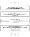
- FIG. 4 is a flow chart showing the flow of processing of the motor control device according to the embodiment
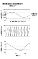
- FIG. 5 is a diagram showing the time histories of the rotation speed (main shaft speed), the rotation angle of the main shaft, and the speed change rate of a conventional main shaft motor, and is a diagram showing the state before changing the speed of the main shaft.
- FIG. 5 is a diagram showing the time history of each of the rotation speed (main shaft speed), the main shaft rotation angle, and the speed change rate of a conventional main shaft motor, and is a diagram showing the state after changing the main shaft speed.
- FIG. 5 is a diagram showing the time histories of the rotation speed (main shaft speed), the rotation angle of the main shaft, and the speed change rate of a conventional main shaft motor, and is a diagram showing the state after changing the main shaft speed.
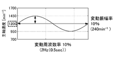
- FIG. 4 is a diagram showing the time history of the rotation speed (spindle speed) of the spindle motor of the present embodiment when the spindle speed is 1200 [min ⁇ 1 ] and the fluctuation amplitude rate and the fluctuation frequency rate are both 10%.
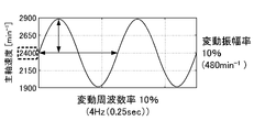
- FIG. 4 is a diagram showing the time history of the rotational speed (spindle speed) of the spindle motor of the present embodiment when the spindle speed is 2400 [min ⁇ 1 ] and the fluctuation amplitude rate and the fluctuation frequency rate are both 10%.
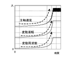
- is. 5 is a diagram showing an example of the time history of the rotational speed (spindle speed), fluctuation amplitude, and fluctuation frequency of the spindle motor of the present embodiment; FIG. FIG.
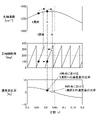
- FIG. 4 is a diagram for explaining the definition of a speed change rate, showing a tool and a workpiece;
- FIG. 4 is a diagram for explaining the definition of a speed change rate, and is a diagram showing the time history of each of the rotation speed of a spindle motor (spindle speed), the spindle rotation angle, and the speed change rate.
- FIG. 1 is a diagram showing an outline of a machine tool according to this embodiment.
- the machine tool is a device that performs predetermined machining such as cutting by controlling the motor control device 1 and rotating the spindle motor 3 based on the speed command from the numerical control device 2 .
- This machine tool suppresses regenerative self-excited chatter vibration by periodically varying the rotational speed of the spindle motor 3, for example, by sinusoidally vibrating the rotational speed of the spindle motor 3.
- the motor control device 1 includes a variation command calculation unit 11, a variation condition setting unit 12, a speed control unit 14, a current control unit 16, and a current detection unit 17.
- the variation command calculation unit 11 generates a variation command based on a variation condition for periodically varying the speed command of the spindle motor 3 in the machine tool and the rotation speed of the spindle motor 3 . Specifically, the fluctuation command calculation unit 11 multiplies the rotation speed of the spindle motor 3 based on the speed command by a fluctuation amplitude rate (hereinafter also simply referred to as an amplitude rate), which is a fluctuation condition, to calculate the periodically fluctuating spindle speed.
- a fluctuation amplitude rate hereinafter also simply referred to as an amplitude rate
- the amplitude of the rotation speed of the motor 3 is calculated, and the rotation speed of the spindle motor 3 based on the speed command is multiplied by a fluctuation frequency rate (hereinafter simply referred to as a frequency rate), which is a fluctuation condition, to periodically fluctuate.
- a variation command is generated by calculating the frequency of the rotational speed of the spindle motor 3 .
- the fluctuation command calculation unit 11 multiplies the rotation speed S [min ⁇ 1 ] of the spindle motor 3 based on the speed command by the amplitude rate a [%], which is the fluctuation condition, to calculate the periodically fluctuating spindle speed S [min ⁇ 1 ].
- the variation condition setting unit 12 sets the amplitude rate a [%] and the frequency rate f [%] as the variation conditions for periodically varying the rotational speed of the spindle motor 3, and outputs them as signals. Input from the machining program, parameters to be set, and the like are adopted for setting the variable conditions.
- Numeral 13 adds the value of the variation command output as a signal from the variation command calculator 11 to the value of the speed command output as a signal from the spindle speed command 21, and outputs the value as a signal from the speed detector 31. It means that a value obtained by subtracting the actual speed feedback value is input to the speed control section 14 as a signal.
- the speed control unit 14 generates a command for controlling the rotation speed of the spindle motor 3 based on the speed command and the variation command, and outputs it as a signal.
- Reference numeral 15 denotes a value obtained by subtracting the actual current feedback value output as a signal from the current detection unit 17 from the value of the command output as a signal from the speed control unit 14, which is used as a signal for current control. It means that it is input to the unit 16 .
- the current control unit 16 Based on the input signal, the current control unit 16 generates a voltage command for driving the spindle motor 3 and outputs it as a signal.
- the current detection unit 17 detects a signal that is the current value of the spindle motor 3, and outputs the detection result as an actual current feedback signal.
- the numerical controller 2 has a spindle speed command 21.
- a spindle speed command 21 generates a speed command for the spindle motor 3 and outputs it as a signal.
- the spindle motor 3 rotates under the control of the motor control device 1.
- the speed detection unit 31 detects the rotation speed of the spindle motor 3 and outputs the detection result as a signal of actual speed feedback.
- An encoder or the like is adopted for the speed detection unit 31 .
- FIG. 2 is a flowchart showing the processing flow of the motor control device 1 according to this embodiment.
- step S11 the fluctuation command calculation unit 11 acquires a speed command as a signal from the spindle speed command 21, and also receives a signal from the fluctuation condition setting unit 12 as an amplitude rate a [%] and a frequency rate f [%], which are fluctuation conditions. ].
- step S14 the fluctuation command calculator 11 calculates a fluctuation command SSV [min -1 ] from the amplitude A [min -1 ] and the frequency F [Hz].
- t[s] means the control cycle of the variation command.
- FIG. 3 is a diagram showing the time history of each of the rotation speed (spindle speed) of the conventional spindle motor, the spindle rotation angle, and the speed change rate, and is a diagram showing before the spindle speed is changed.
- FIG. 4 is a diagram showing the time histories of the rotational speed (main shaft speed), the rotational angle of the main shaft, and the speed change rate of a conventional main shaft motor, and shows the state after the main shaft speed is changed.
- the amplitude and frequency of the periodically fluctuating spindle speed command in a conventional spindle motor are determined by absolute values. For example, as shown in FIG. 3, when the spindle speed is 1200 ⁇ 240 [min ⁇ 1 ], that is, when the amplitude is 240 [min ⁇ 1 ], the speed change rate changes between ⁇ 10% and 10%. On the other hand, as shown in FIG. 4, when the spindle speed is changed from 1200 [min -1 ] to 2400 [min -1 ] while the amplitude remains 240 [min -1 ], the speed change rate is It will remain around -5% to 5%. As described above, in the conventional spindle motor, the rate of change in speed becomes small, and the regenerative self-excited chatter vibration suppressing effect cannot be stably obtained.
- FIG. 5 is a diagram showing the time history of the rotation speed (spindle speed) of the spindle motor of this embodiment. It is a figure which shows the time of .
- FIG. 6 is a diagram showing the time history of the rotation speed (spindle speed) of the spindle motor of this embodiment.
- FIG. 4 is a diagram showing when;
- the amplitude and frequency of the periodically varying spindle speed command in the spindle motor are determined by ratios. Therefore, in the example shown in FIG. 5, the fluctuation amplitude is 240 [min ⁇ 1 ] and the fluctuation frequency is 2 Hz (0.5 sec), and in the example shown in FIG . are different from each other at 4 Hz (0.25 sec), but the fluctuation amplitude rate and the fluctuation frequency rate are both the same at 10%. Therefore, the speed change rate is kept constant regardless of the spindle speed.
- FIG. 7 is a diagram showing an example of the time history of the rotational speed (spindle speed), fluctuation amplitude, and fluctuation frequency of the spindle motor of this embodiment.
- spindle speed the fluctuation amplitude and fluctuation frequency also increase. That is, since the fluctuation amplitude rate and the fluctuation frequency rate are constant regardless of the spindle speed, the speed change rate is kept constant. Therefore, a stable regenerative self-excited chatter vibration suppression effect can be obtained.
- FIG. 8 is a diagram for explaining the definition of the speed change rate, showing a tool and a work.
- FIG. 9 is a diagram for explaining the definition of the speed change rate, and shows time histories of the rotation speed (spindle speed) of the spindle motor 3, the spindle rotation angle, and the speed change rate.
- the direction of the rotational speed (spindle speed) of the spindle motor 3 is the direction in which the workpiece rotates, and is indicated by an arrow in FIG.
- the rotation angle of the main shaft of the main shaft motor 3 is from 0 degrees to 360 degrees for one rotation.
- the rotation speed (main shaft speed) of the main shaft motor 3 is 1315 [min ⁇ 1 ], and the main shaft rotation angle of the main shaft motor 3 is 100 degrees.
- the spindle speed is 1285 [min ⁇ 1 ] and the rotation angle of the spindle is 100 degrees as at time point A.
- the rate of change in speed at point A is obtained from the ratio of the speed difference between the spindle speed 1315 [min ⁇ 1 ] at point A and the spindle speed 1285 [min ⁇ 1 ] at the point one revolution before point A.
- the rotational speed (main shaft speed) of the main shaft motor 3 is 1315 [min ⁇ 1 ], and the main shaft rotation angle of the main shaft motor 3 is 300 degrees.
- the spindle speed is 1305 [min ⁇ 1 ], and the rotation angle of the spindle is 300 degrees as at time B.
- the speed change rate at time B is obtained from the ratio of the speed difference between the spindle speed 1315 [min ⁇ 1 ] at time B and the spindle speed 1305 [min ⁇ 1 ] at the time one round before time B.
- the spindle speed command is varied so that the rate of change in speed defined as described above is constant. Specifically, the fluctuation amplitude and fluctuation frequency are given at a rate corresponding to the spindle speed command. As a result, the speed change rate is kept constant regardless of the spindle speed command.
- a motor control device 1 includes a variation command calculation unit that generates a variation command based on a variation condition for periodically varying a speed command of a spindle motor 3 in a machine tool 1 and a rotational speed of the spindle motor 3. 11, and a speed control unit 14 for controlling the rotation speed of the spindle motor 3 based on the speed command and the variation command. and the frequency of the rotation speed of the spindle motor 3, which periodically fluctuates, to generate a fluctuation command.
- the speed change rate is kept constant. , a stable regenerative self-excited chatter vibration suppression effect can be obtained.
- the fluctuation command calculation unit 11 causes the spindle motor 3 to periodically fluctuate based on the rotation speed of the spindle motor 3 based on the speed command and the amplitude rate as the fluctuation condition.
- a variation command is generated by calculating the amplitude of the rotational speed of 3.
- the motor control device 1 can be realized by hardware, software, or a combination thereof. Also, the control method performed by the motor control device 1 can be implemented by hardware, software, or a combination thereof. Note that "implemented by software” means implemented by a computer reading and executing a program.
Landscapes
- Engineering & Computer Science (AREA)
- Mechanical Engineering (AREA)
- Human Computer Interaction (AREA)
- Manufacturing & Machinery (AREA)
- Physics & Mathematics (AREA)
- General Physics & Mathematics (AREA)
- Automation & Control Theory (AREA)
- Automatic Control Of Machine Tools (AREA)
- Control Of Electric Motors In General (AREA)
- Numerical Control (AREA)
Abstract
Description
図8は、速度変化率の定義を説明するための図であり、工具及びワークを示す図である。図9は、速度変化率の定義を説明するための図であり、主軸モータ3の回転速度(主軸速度)、主軸回転角度、及び速度変化率の各々の時刻歴を示す図である。
これにより、主軸速度指令の異なる加工プログラムや主軸速度指令が加工途中で変化するような加工の場合、例えば主軸オーバライド時や周速一定制御時等においても、速度変化率が一定に保たれるため、安定した再生型の自励びびり振動抑制効果を得ることができる。
これにより、上記効果をより安定して得ることができる。
11 変動指令計算部
12 変動条件設定部
14 速度制御部
16 電流制御部
17 電流検出部
2 数値制御装置
21 主軸速度指令
3 主軸モータ
31 速度検出部
Claims (2)
- 工作機械における主軸モータの速度指令及び前記主軸モータの回転速度を周期的に変動させるための変動条件に基づいて変動指令を生成する変動指令計算部と、
前記速度指令及び前記変動指令に基づいて前記主軸モータの回転速度を制御する速度制御部と、を備え、
前記変動指令計算部は、前記速度指令に基づく前記主軸モータの回転速度と、前記変動条件である周波数率と、に基づいて、周期的に変動する前記主軸モータの回転速度の周波数を計算することで、前記変動指令を生成する、工作機械の制御装置。 - 前記変動指令計算部は、前記速度指令に基づく前記主軸モータの回転速度と、前記変動条件である振幅率と、に基づいて、周期的に変動する前記主軸モータの回転速度の振幅を計算することで、前記変動指令を生成する、請求項1に記載の工作機械の制御装置。
Priority Applications (4)
| Application Number | Priority Date | Filing Date | Title |
|---|---|---|---|
| US18/548,466 US20240227106A9 (en) | 2021-03-18 | 2022-03-14 | Machine tool controller |
| CN202280015503.9A CN116867604A (zh) | 2021-03-18 | 2022-03-14 | 机床的控制装置 |
| DE112022000659.5T DE112022000659T5 (de) | 2021-03-18 | 2022-03-14 | Werkzeugmaschinensteuerung |
| JP2023507109A JPWO2022196645A1 (ja) | 2021-03-18 | 2022-03-14 |
Applications Claiming Priority (2)
| Application Number | Priority Date | Filing Date | Title |
|---|---|---|---|
| JP2021-044400 | 2021-03-18 | ||
| JP2021044400 | 2021-03-18 |
Publications (1)
| Publication Number | Publication Date |
|---|---|
| WO2022196645A1 true WO2022196645A1 (ja) | 2022-09-22 |
Family
ID=83320382
Family Applications (1)
| Application Number | Title | Priority Date | Filing Date |
|---|---|---|---|
| PCT/JP2022/011372 Ceased WO2022196645A1 (ja) | 2021-03-18 | 2022-03-14 | 工作機械の制御装置 |
Country Status (5)
| Country | Link |
|---|---|
| US (1) | US20240227106A9 (ja) |
| JP (1) | JPWO2022196645A1 (ja) |
| CN (1) | CN116867604A (ja) |
| DE (1) | DE112022000659T5 (ja) |
| WO (1) | WO2022196645A1 (ja) |
Citations (2)
| Publication number | Priority date | Publication date | Assignee | Title |
|---|---|---|---|---|
| JP2000126991A (ja) * | 1998-10-24 | 2000-05-09 | Hitachi Seiki Co Ltd | Nc工作機械の制御装置 |
| JP2015112676A (ja) * | 2013-12-11 | 2015-06-22 | 国立大学法人 東京大学 | 加工方法 |
Family Cites Families (4)
| Publication number | Priority date | Publication date | Assignee | Title |
|---|---|---|---|---|
| EP1980925B1 (en) * | 2007-04-13 | 2013-12-18 | Océ-Technologies B.V. | Method and control unit for controlling the power supplied to a plurality of heat sources in a printer |
| US20110220628A1 (en) * | 2010-03-10 | 2011-09-15 | Illinois Tool Works Inc. | Wire feed motor control systems and methods |
| JP5665047B2 (ja) | 2010-10-27 | 2015-02-04 | オークマ株式会社 | 工作機械 |
| FR3028839B1 (fr) * | 2014-11-26 | 2016-11-18 | Airbus Helicopters | Methode d'assistance a la navigation d'un giravion multimoteur en cas de panne moteur, dans le cadre d'un entrainement a vitesse variable d'un rotor principal du giravion |
-
2022
- 2022-03-14 WO PCT/JP2022/011372 patent/WO2022196645A1/ja not_active Ceased
- 2022-03-14 DE DE112022000659.5T patent/DE112022000659T5/de active Pending
- 2022-03-14 JP JP2023507109A patent/JPWO2022196645A1/ja active Pending
- 2022-03-14 US US18/548,466 patent/US20240227106A9/en active Pending
- 2022-03-14 CN CN202280015503.9A patent/CN116867604A/zh not_active Withdrawn
Patent Citations (2)
| Publication number | Priority date | Publication date | Assignee | Title |
|---|---|---|---|---|
| JP2000126991A (ja) * | 1998-10-24 | 2000-05-09 | Hitachi Seiki Co Ltd | Nc工作機械の制御装置 |
| JP2015112676A (ja) * | 2013-12-11 | 2015-06-22 | 国立大学法人 東京大学 | 加工方法 |
Also Published As
| Publication number | Publication date |
|---|---|
| US20240131647A1 (en) | 2024-04-25 |
| US20240227106A9 (en) | 2024-07-11 |
| JPWO2022196645A1 (ja) | 2022-09-22 |
| CN116867604A (zh) | 2023-10-10 |
| DE112022000659T5 (de) | 2023-10-26 |
Similar Documents
| Publication | Publication Date | Title |
|---|---|---|
| JP5908342B2 (ja) | 工作機械の加工振動抑制方法及び加工振動抑制装置 | |
| JP5160980B2 (ja) | 振動抑制方法及び装置 | |
| JP6243260B2 (ja) | 主軸モータの制御装置 | |
| JP7444697B2 (ja) | 数値制御装置、制御プログラム及び制御方法 | |
| JP6503001B2 (ja) | 揺動切削を行う工作機械の制御装置 | |
| JP7044734B2 (ja) | サーボ制御装置 | |
| WO2012133222A1 (ja) | 工作機械及びその加工制御装置 | |
| JP5917251B2 (ja) | びびり振動の抑制システム及び抑制方法 | |
| CN112130524B (zh) | 数值控制装置、程序记录介质以及控制方法 | |
| JP2021096839A (ja) | 工作機械の制御装置及び工作機械制御方法 | |
| JP7522180B2 (ja) | 工作機械の制御装置 | |
| JP7036786B2 (ja) | 数値制御装置、プログラム及び制御方法 | |
| JP2018181100A (ja) | 揺動切削を行う工作機械の制御装置 | |
| JP2015112676A (ja) | 加工方法 | |
| WO2022196645A1 (ja) | 工作機械の制御装置 | |
| JP7575569B2 (ja) | 工作機械の制御装置 | |
| JP7280310B2 (ja) | 数値制御装置 | |
| CN112449617A (zh) | 加工装置和切削加工方法 | |
| JP5494378B2 (ja) | ねじ切り制御方法及びその装置 | |
| JP5301946B2 (ja) | 振動抑制方法及び装置 | |
| JP5767931B2 (ja) | 工作機械の振動抑制方法および振動抑制装置 | |
| WO2024053027A1 (ja) | 工作機械制御装置および工作機械制御プログラム | |
| WO2023067683A1 (ja) | 工作機械の制御装置 | |
| JP2013250866A (ja) | 工作機械を用いた被加工物の加工方法 | |
| WO2022009925A1 (ja) | 工作機械の制御装置 |
Legal Events
| Date | Code | Title | Description |
|---|---|---|---|
| 121 | Ep: the epo has been informed by wipo that ep was designated in this application |
Ref document number: 22771391 Country of ref document: EP Kind code of ref document: A1 |
|
| WWE | Wipo information: entry into national phase |
Ref document number: 2023507109 Country of ref document: JP |
|
| WWE | Wipo information: entry into national phase |
Ref document number: 202280015503.9 Country of ref document: CN |
|
| WWE | Wipo information: entry into national phase |
Ref document number: 18548466 Country of ref document: US |
|
| WWE | Wipo information: entry into national phase |
Ref document number: 112022000659 Country of ref document: DE |
|
| 122 | Ep: pct application non-entry in european phase |
Ref document number: 22771391 Country of ref document: EP Kind code of ref document: A1 |