WO2022196193A1 - 超電導モータ - Google Patents
超電導モータ Download PDFInfo
- Publication number
- WO2022196193A1 WO2022196193A1 PCT/JP2022/005036 JP2022005036W WO2022196193A1 WO 2022196193 A1 WO2022196193 A1 WO 2022196193A1 JP 2022005036 W JP2022005036 W JP 2022005036W WO 2022196193 A1 WO2022196193 A1 WO 2022196193A1
- Authority
- WO
- WIPO (PCT)
- Prior art keywords
- superconducting
- coil
- inner peripheral
- container
- rotor
- Prior art date
- Legal status (The legal status is an assumption and is not a legal conclusion. Google has not performed a legal analysis and makes no representation as to the accuracy of the status listed.)
- Ceased
Links
Images

Classifications
-
- H—ELECTRICITY
- H02—GENERATION; CONVERSION OR DISTRIBUTION OF ELECTRIC POWER
- H02K—DYNAMO-ELECTRIC MACHINES
- H02K55/00—Dynamo-electric machines having windings operating at cryogenic temperatures
- H02K55/02—Dynamo-electric machines having windings operating at cryogenic temperatures of the synchronous type
-
- Y—GENERAL TAGGING OF NEW TECHNOLOGICAL DEVELOPMENTS; GENERAL TAGGING OF CROSS-SECTIONAL TECHNOLOGIES SPANNING OVER SEVERAL SECTIONS OF THE IPC; TECHNICAL SUBJECTS COVERED BY FORMER USPC CROSS-REFERENCE ART COLLECTIONS [XRACs] AND DIGESTS
- Y02—TECHNOLOGIES OR APPLICATIONS FOR MITIGATION OR ADAPTATION AGAINST CLIMATE CHANGE
- Y02E—REDUCTION OF GREENHOUSE GAS [GHG] EMISSIONS, RELATED TO ENERGY GENERATION, TRANSMISSION OR DISTRIBUTION
- Y02E40/00—Technologies for an efficient electrical power generation, transmission or distribution
- Y02E40/60—Superconducting electric elements or equipment; Power systems integrating superconducting elements or equipment
Definitions
- the present invention relates to superconducting motors used as power sources for ships, railroads, vehicles, aircraft, etc., for example.
- a conventional superconducting motor has a rotor that is rotatably supported, a stator core and superconducting coils, a stator arranged to face the rotor in the radial direction, a coil cooling means that cools the superconducting coils, is known (see, for example, Patent Document 1).
- the coil cooling means of a conventional superconducting motor cools the stator core by circulating a cooling medium discharged from a refrigerator through narrow tubes formed to penetrate the stator core, and the cooled stator core heats the stator core. It cools the connected superconducting coils. Therefore, when the conventional superconducting motor is started, a large amount of cooling medium is consumed to cool the superconducting coil to the superconducting state, and it may take a long time to reach the superconducting state.
- An object of the present invention is to provide a superconducting motor that can efficiently cool the superconducting coils at startup.
- a superconducting motor includes a rotor that is rotatably supported, a stator core, and a plurality of superconducting coils.
- a coil cooling container into which a cooling medium for cooling the superconducting coil flows; and a heat insulating container in which the stator core and the coil cooling container are accommodated.
- a plurality of teeth arranged at intervals in the circumferential direction and protruding in the radial direction of the yoke portion, the coil cooling vessel extending inward from the outer surface, It has a plurality of insertion paths through which teeth are inserted, and the superconducting coil is wound around the outer periphery of the insertion paths inside the coil cooling container.
- the stator is disposed radially outward of the rotor
- the heat insulating container is formed in a tubular shape surrounding the outer peripheral side of the rotor, and is an outer peripheral side member located on the outer peripheral side. and an inner peripheral side member located on the inner peripheral side, the inner peripheral side member being formed of a non-magnetic and non-conductive material.
- the coil cooling container is supported by the inner peripheral member.
- the tooth portion is arranged radially inside the yoke portion, and the tip portion is supported by the inner peripheral member.
- the teeth are separate from the yoke.
- the present invention it is possible to cool only the superconducting coil without cooling the stator core by allowing the cooling medium to flow into the coil cooling container, so that the superconducting coil can be efficiently cooled at the time of start-up. becomes possible.
- FIG. 1 is an overall perspective view of a superconducting motor according to one embodiment of the present invention
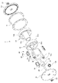
- FIG. 1 is an exploded perspective view of a superconducting motor according to one embodiment of the present invention
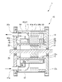
- FIG. 1 is a cross-sectional view of a superconducting motor according to one embodiment of the present invention
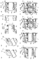
- FIG. It is a figure explaining a method of assembling a superconducting motor concerning one embodiment of the present invention.
- FIG. 1 is an overall perspective view of a superconducting motor
- FIG. 2 is an exploded perspective view of the superconducting motor
- FIG. 3 is a cross-sectional view of the superconducting motor
- FIG. 4 is a diagram for explaining a method of assembling the superconducting motor.
- the superconducting motor 1 of this embodiment is used as a power source for ships, railroads, vehicles, aircraft, and the like, for example.
- the superconducting motor 1 includes a heat insulating container 10, a drive shaft 20 rotatably provided with respect to the heat insulating container 10, and a rotor 30 fixed to the outer peripheral portion of the drive shaft 20. and a stator 40 provided inside the heat insulating container 10, facing the rotor 30 on the radially outer side of the rotor 30, and a superconducting coil described later of the stator 40 are accommodated, and a cooling medium for cooling the superconducting coil is circulated.
- a container 50 ;
- the heat insulating container 10 includes a cylindrical outer member 11 located on the outer peripheral side, a cylindrical inner peripheral member 12 located on the inner peripheral side, and one axial end of the outer peripheral member 11 and the inner peripheral member 12. and a second lid member 14 that closes the other ends in the axial direction of the outer peripheral side member 11 and the inner peripheral side member 12 .
- the inner peripheral side member 12 is provided on one end side of the inner peripheral cylindrical portion 12a extending between the first lid member 13 and the second lid member 14 and the inner peripheral cylindrical portion 12a. and a fitting portion 12b that fits into.
- the heat-insulating container 10 has a cylindrical closed cylindrical space 10 a surrounded by an outer peripheral member 11 , an inner peripheral member 12 , a first lid member 13 and a second lid member 14 .
- the heat-insulating container 10 evacuates the closed cylindrical space 10a to evacuate the closed cylindrical space 10a, thereby blocking heat transfer between the inside and the outside of the closed cylindrical space 10a.
- the inner peripheral side member 12 is made of a non-magnetic and non-conductive material.
- Non-magnetic and non-conductive materials include fiber-reinforced plastics such as GFRP, polyimide (PI), polyamide-imide (PAI), polybenzimidazole (PBI), polyetheretherketone (PEEK), and fluorine resin (PTFE). ), which can be used in a wide range of temperatures (especially low temperatures) such as super engineering plastics, ceramic processed products such as alumina, and glass materials.
- the drive shaft 20 is arranged so as to extend in the axial direction on the inner peripheral side of the inner peripheral cylindrical portion 12 a of the inner peripheral side member 12 . It is rotatably supported, and the other end side is rotatably supported by a radially central portion of the second lid member 14 via a second bearing 22 .
- the rotor 30 is provided on the outer peripheral portion of the drive shaft 20 on the axial center side, and has an outer diameter slightly smaller than the inner diameter of the inner peripheral cylindrical portion 12 a of the inner peripheral side member 12 .
- the rotor 30 includes a rotor core 31 integrally formed by laminating a plurality of electromagnetic steel plates in the axial direction of the drive shaft 20 and by caulking, welding, or the like, and ferrite magnets, for example, arranged circumferentially around the outer periphery of the rotor core 31. and a plurality of permanent magnets 32 of .
- the stator 40 has a stator core 41 housed in the closed cylindrical space 10a of the heat insulating container 10, and a plurality of superconducting coils 42 housed in a coolant circulation space (described later) of the coil cooling container 50.
- the stator core 41 is constructed by integrally forming a plurality of laminated electromagnetic steel plates by caulking, welding, or the like.
- the stator core 41 includes a yoke portion 41a formed in an annular shape, a plurality of tooth portions 41b projecting toward the center of the annular shape at intervals in the circumferential direction of the annular shape of the yoke portion 41a, have.
- the stator core 41 has a yoke portion 41a and a plurality of teeth portions 41b that are separate from each other.
- the tooth portion 41b of the coil cooling vessel 50 is supported by the outer peripheral portion of the inner peripheral cylindrical portion 12a of the inner peripheral side member 12 in a state of being inserted into an insertion passage, which will be described later.
- the stator core 41 has a plurality of tooth portions 41b attached to the yoke portions 41a.
- Each of the plurality of superconducting coils 42 is made of a wire made of, for example, a bismuth (Bi2)-based or yttrium (Y)-based superconducting material, and as shown in FIG. is wrapped around. As shown in FIG. 3, the plurality of superconducting coils 42 are arranged on the outer peripheral side of the tooth portion 41b via insertion passages of the coil cooling vessel 50, which will be described later.
- the superconducting motor 1 of the present embodiment includes a concentrated winding stator 40 in which a superconducting coil 42 is concentratedly wound around each of a plurality of tooth portions 41b of a stator core 41 . Electricity flowing through the plurality of superconducting coils 42 is supplied from a current introducing portion 42 b provided in the second lid member 14 .
- the coil cooling vessel 50 has a tubular external shape in which a tubular refrigerant circulation space 50a extending along the circumferential direction of the sealed tubular space 10a of the heat insulating vessel 10 is formed. and supported by the inner peripheral side member 12 of the heat insulating container 10 .
- the refrigerant circulation space 50a is arranged at intervals with respect to each of the outer peripheral side member 11, the inner peripheral side member 12, the first lid member 13, and the second lid member 14. Heat transfer between the outside and the coolant flow space 50a is cut off.
- the coil cooling vessels 50 are provided at intervals in the circumferential direction at substantially the central portion in the axial direction, and are formed so as to extend inward from the outer surface of the plurality of teeth 41 b of the stator core 41 . It has a plurality of insertion passages 50b through which each is inserted. In the present embodiment, the plurality of insertion passages 50b penetrate the coolant circulation space 50a to communicate the outer peripheral side and the inner peripheral side of the coil cooling vessel 50, respectively.
- the coil cooling vessel 50 is formed integrally with the plurality of superconducting coils 42 by setting the superconducting coils 42 on the outer peripheral side of each of the plurality of insertion passages 50b in the process of forming the coolant circulation space 50a. .
- a coolant inflow pipe 51 for inflowing a cooling medium is connected to the lower side of the outer peripheral surface of the coil cooling vessel 50, and a coolant outflow pipe 52 for flowing out the cooling medium is connected to the upper side of the outer peripheral surface.
- a coolant inflow end 51 a of the coolant inflow pipe 51 into which the cooling medium flows and a coolant outflow end 52 a of the coolant outflow pipe 52 into which the cooling medium flows are respectively arranged on the second lid member 14 .
- Liquid nitrogen is used as the cooling medium that flows into the coil cooling container 50.
- the superconducting coil 42 housed in the coil cooling container 50 is cooled by the liquid nitrogen, and the nitrogen vaporized by cooling the superconducting coil 42 flows out of the coolant. It flows out from the end 52a.
- the yoke portion 41a of the stator core 41 is assembled to the inner peripheral side member 12 of the heat insulating container 10. Then, as shown in FIG.
- the coil cooling container 50 housing the superconducting coil 42 and the plurality of stator cores 41 are mounted on the inner peripheral member 12 and the yoke portion 41a.
- the tooth portion 41b is assembled.
- the tooth portion 41b is inserted into the insertion passage 50b.
- the plurality of teeth 41b are supported by the inner cylindrical portion 12a and enter the inner circumference of the yoke 41a, and the yoke 41a and the plurality of teeth 41b are assembled. .
- the first lid member 13 is attached to one end of the inner peripheral side member 12 as shown in FIG. 4(e).
- the outer peripheral member 11 is fitted into the fitting portion 12b of the inner peripheral member 12 as shown in FIG. 4(f). together with the first lid member 13 .
- the drive shaft 20 and the rotor 30 assembled together are inserted into the inner peripheral side of the inner cylindrical portion 12a of the inner peripheral member 12, as shown in FIG. 4(g).
- one end side of the drive shaft 20 is supported by the first lid member 13 via the first bearing 21 .
- the other ends of the outer peripheral member 11 and the inner peripheral member 12 are closed by the second cover member 14, and the other end of the drive shaft 20 is closed to the second end. It is supported by the second lid member 14 via the bearing 22 .
- the superconducting motor 1 configured as described above is started, the superconducting coil 42 accommodated in the coil cooling container 50 is cooled by flowing a cooling medium into the coil cooling container 50 to bring it into a superconducting state. As a result, the superconducting motor 1 suppresses the occurrence of copper loss in the superconducting coil 42 during driving.
- the coil cooling container 50 of the superconducting motor 1 accommodates only the superconducting coil 42 , and the stator core 41 is accommodated in the sealed cylindrical space 10 a outside the coil cooling container 50 . Therefore, the superconducting motor 1 of the present embodiment requires a small amount of cooling medium to be consumed until the superconducting coil 42 is brought into the superconducting state, and the superconducting coil 42 can be brought into the superconducting state in a short period of time. . Further, the superconducting motor 1 of the present embodiment suppresses an increase in iron loss due to cooling of the stator core 41 by the cooling medium during driving.
- the inner peripheral side member 12 of the heat insulating container 10 is made of a non-magnetic and non-conductive material. Therefore, the superconducting motor 1 of the present embodiment suppresses an increase in eddy current loss caused by the magnetic flux lines interlinking with the conductive material without restricting the inflow of the magnetic flux lines between the rotor 30 and the stator 40. It becomes possible to
- the inner peripheral side member 12 of the heat insulating container 10 supports the plurality of teeth 41b and the coil cooling container 50 respectively. Therefore, in the superconducting motor 1 of the present embodiment, the plurality of teeth 41b and the coil cooling container 50 do not come into direct contact with each other, and it is possible to suppress mutual heat transfer. It is possible to intensively cool only the superconducting coil 42 housed in the cooling container 50 .
- the rotor 30 is rotatably supported, the stator core 41 and the plurality of superconducting coils 42 are arranged so as to face the rotor 30 in the radial direction.
- a coil cooling container 50 into which a cooling medium for cooling the superconducting coil 42 flows; 41 has an annular yoke portion 41a and a plurality of tooth portions 41b arranged at intervals in the circumferential direction of the yoke portion 41a and protruding in the radial direction of the yoke portion 41a.
- the superconducting coil 42 has a plurality of insertion passages 50b formed to extend inward from the outer surface and through which the tooth portions 41b are inserted. is turned.
- the coil cooling vessel 50 since the coil cooling vessel 50 only needs to be large enough to accommodate only the superconducting coil 42, the required space is smaller than in the case of forming a cooling vessel that accommodates the stator core 41 and the superconducting coil 42. It is possible to reduce the size and weight of the device.
- the stator 40 is disposed radially outward of the rotor 30, and the heat insulating container 10 is formed in a cylindrical shape surrounding the outer peripheral side of the rotor 30, and includes an outer peripheral member 11 positioned on the outer peripheral side and a It is preferable that the inner peripheral member 12 is made of a non-magnetic and non-conductive material.
- the coil cooling container 50 is supported by the inner peripheral member 12 .
- the tooth portion 41b be arranged radially inward of the yoke portion 41a and that the tip portion thereof be supported by the inner peripheral side member 12 .
- stator 40 can be securely fixed in the sealed cylindrical space 10a of the heat insulating container 10 without requiring a special fixing structure for fixing the stator 40.
- the tooth portion 41b be separate from the yoke portion 41a.
- the stator core 41 and the superconducting coil 42 accommodated in the coil cooling container 50 can be easily rotated. can be assembled, it is possible to reduce the number of assembly man-hours.
- the inner rotor type superconducting motor 1 is shown in which the rotor 30 having the permanent magnets 32 is arranged on the inner peripheral side and the stator 40 having the superconducting coils 42 is arranged on the outer peripheral side.
- the present invention can also be applied to an outer rotor type superconducting motor in which a rotor having permanent magnets is arranged on the outer peripheral side and a stator having superconducting coils is arranged on the inner peripheral side.
- liquid nitrogen is used as the cooling medium in the above embodiment, it is not limited to this, and liquid helium may be used as the cooling medium as long as the superconducting coil can be cooled. good.
- the closed cylindrical space 10a is evacuated to form a vacuum heat insulating layer on the heat insulating container 10, but the present invention is not limited to this. If it is possible to block heat transfer between the outside and the inside of the coil cooling vessel, for example, the outside of the coil cooling vessel may be covered with a heat insulating material.
- Reference Signs List 1 superconducting motor 10 heat insulation container 11 outer peripheral member 12 inner peripheral member 30 rotor 40 stator 41 stator core 41a yoke portion 41b tooth portion 42 superconducting coil 50 coil cooling container 50b insertion path
Landscapes
- Engineering & Computer Science (AREA)
- Power Engineering (AREA)
- Superconductive Dynamoelectric Machines (AREA)
Abstract
始動時において、超電導コイルを効率的に冷却することのできる超電導モータを提供する。 ステータコア41および複数の超電導コイル42を有し、ロータ30に対して径方向に対向するように配置されるステータ40と、超電導コイル42が収容され、超電導コイル42を冷却する冷却媒体が流入するコイル冷却容器50と、ステータコア41およびコイル冷却容器50が収容される断熱容器10と、を備え、ステータコア41は、環状のヨーク部41aと、ヨーク部41aの周方向に間隔をおいて配置され、ヨーク部41aの径方向に突出する複数のティース部41bと、を有し、コイル冷却容器50は、外面から内側に向かって延出するように形成され、ティース部41bが挿通される複数の挿通路50bを有し、超電導コイル42は、コイル冷却容器50の内側における挿通路50bの外周側に巻き回される。
Description
本発明は、例えば、船舶、鉄道、車両、航空機等の動力源として用いられる超電導モータに関するものである。
従来の超電導モータは、回転自在に支持されるロータと、ステータコアおよび超電導コイルを有し、ロータに対して径方向に対向するように配置されるステータと、超電導コイルを冷却するコイル冷却手段と、を備えたのものが知られている(例えば、特許文献1参照)。
従来の超電導モータのコイル冷却手段は、冷凍機から吐出された冷却媒体を、ステータコアを貫通するように形成された細管に流通させることによってステータコアを冷却し、冷却したステータコアによって、ステータコアと熱的に接続された超電導コイルを冷却するようになっている。このため、従来の超電導モータは、始動時において、超電導コイルを超電導の状態となるまで冷却する際に消費される冷却媒体の量が多くなるとともに、超電導の状態となるまでに長時間を要するおそれがある。
本発明の目的とするところは、始動時において、超電導コイルを効率的に冷却することのできる超電導モータを提供することにある。
本発明に係る超電導モータは、回転自在に支持されるロータと、ステータコアおよび複数の超電導コイルを有し、前記ロータに対して径方向に対向するように配置されるステータと、前記超電導コイルが収容され、前記超電導コイルを冷却する冷却媒体が流入するコイル冷却容器と、前記ステータコアおよび前記コイル冷却容器が収容される断熱容器と、を備え、前記ステータコアは、環状のヨーク部と、前記ヨーク部の周方向に間隔をおいて配置され、前記ヨーク部の径方向に突出する複数のティース部と、を有し、前記コイル冷却容器は、外面から内側に向かって延出するように形成され、前記ティース部が挿通される複数の挿通路を有し、前記超電導コイルは、前記コイル冷却容器の内側における前記挿通路の外周側に巻き回される。
また、本発明に係る超電導モータは、前記ステータが、前記ロータの径方向外側に配置され、前記断熱容器は、前記ロータの外周側を囲む筒状に形成され、外周側に位置する外周側部材と、内周側に位置する内周側部材と、を有し、前記内周側部材は、非磁性かつ非導電性を有する材料によって形成されている。
また、本発明に係る超電導モータは、前記コイル冷却容器が、前記内周側部材に支持されている。
また、本発明に係る超電導モータは、前記ティース部が、前記ヨーク部の径方向内側に配置され、先端部が前記内周側部材に支持されている。
また、本発明に係る超電導モータは、前記ティース部が、前記ヨーク部と別体である。
本発明によれば、コイル冷却容器に冷却媒体を流入させることによって、ステータコアを冷却することなく、超電導コイルのみを冷却することが可能となるので、始動時において、超電導コイルを効率的に冷却することが可能となる。
図1乃至図4は、本発明の一実施形態を示すものである。図1は超電導モータの全体斜視図であり、図2は超電導モータの分解斜視図であり、図3は超電導モータの断面図であり、図4は超電導モータを組み立てる方法を説明する図である。
本実施形態の超電導モータ1は、例えば、船舶、鉄道、車両、航空機等の動力源として用いられるものである。
この超電導モータ1は、図1および図2に示すように、断熱容器10と、断熱容器10に対して回転自在に設けられた駆動軸20と、駆動軸20の外周部に固定されたロータ30と、断熱容器10の内側に設けられ、ロータ30の径方向外側においてロータ30と対向するステータ40と、ステータ40の後述する超電導コイルが収容され、超電導コイルを冷却する冷却媒体が流通するコイル冷却容器50と、を備えている。
断熱容器10は、外周側に位置する円筒状の外周側部材11と、内周側に位置する円筒状の内周側部材12と、外周側部材11および内周側部材12の軸方向一端部を閉鎖する第1蓋部材13と、外周側部材11および内周側部材12の軸方向他端部を閉鎖する第2蓋部材14と、を有している。内周側部材12は、第1蓋部材13と第2蓋部材14との間にわたって延びる内周円筒部12aと、内周円筒部12aの一端側に設けられ、外周側部材11の内周面に嵌合する嵌合部12bと、を有している。断熱容器10は、外周側部材11、内周側部材12、第1蓋部材13及び第2蓋部材14によって囲まれる円筒形状の密閉筒状空間10aを有している。断熱容器10は、密閉筒状空間10aの真空引きを行うことによって、密閉筒状空間10aを真空状態とし、密閉筒状空間10aの内側と外側との間の熱の伝達を遮断する。また、内周側部材12は、非磁性かつ非導電性を有する材料によって形成されている。非磁性かつ非導電性を有する材料としては、GFRPに代表される繊維強化プラスチック、ポリイミド(PI)、ポリアミドイミド(PAI)、ポリベンゾイミダゾール(PBI)ポリエーテルエーテルケトン(PEEK)、フッ素樹脂(PTFE)等のスーパーエンジニアリングプラスチックといった広範囲の温度(特に低温)で使用可能な高強度樹脂材料、アルミナ等のセラミックス加工品、ガラス素材等があげられる。
駆動軸20は、内周側部材12の内周円筒部12aの内周側を軸方向に延びるように配置され、一端側が第1蓋部材13の径方向中央部に第1軸受21を介して回転自在に支持され、他端側が第2蓋部材14の径方向中央部に第2軸受22を介して回転自在に支持されている。
ロータ30は、駆動軸20の軸方向中央部側の外周部に設けられ、内周側部材12の内周円筒部12aの内径よりもやや小さい外径を有している。ロータ30は、駆動軸20の軸方向に複数の電磁鋼鈑を積層し、カシメや溶接等によって一体に形成されたロータコア31と、ロータコア31の外周部に周方向に配置ざれた例えばフェライト磁石等の複数の永久磁石32と、を有している。
ステータ40は、断熱容器10の密閉筒状空間10aに収容されるステータコア41と、コイル冷却容器50の後述する冷媒流通空間に収容される複数の超電導コイル42と、を有している。
ステータコア41は、積層した複数の電磁鋼鈑を、カシメや溶接等によって一体に形成することによって構成される。ステータコア41は、円環状に形成されたヨーク部41aと、それぞれヨーク部41aの円環形状の周方向に間隔をおいて、円環形状の中心側に向かって突出する複数のティース部41bと、を有している。ステータコア41は、図3及び図4に示すように、ヨーク部41aと複数のティース部41bとがそれぞれ別体であり、ヨーク部41aが内周側部材12の嵌合部12bに支持され、複数のティース部41bがコイル冷却容器50の後述する挿通路に挿通された状態で内周側部材12の内周円筒部12aの外周部に支持される。ステータコア41は、超電導モータ1を組み付ける際に、ヨーク部41aに対して複数のティース部41bが組付けられる。
複数の超電導コイル42は、それぞれ、例えば、ビスマス(Bi2)系またはイットリウム(Y)系の超電導材料からなる線材からなり、図2に示すように、環状に形成されたコイル枠42aの外周部に巻き掛けられている。複数の超電導コイル42は、図3に示すように、それぞれコイル冷却容器50の後述する挿通路を介してティース部41bの外周側に配置される。本実施形態の超電導モータ1は、ステータコア41の複数のティース部41bのそれぞれに集中して超電導コイル42が巻き回される集中巻きのステータ40が構成されている。また、複数の超電導コイル42を流れる電気は、第2蓋部材14に設けられた電流導入部42bから供給される。
コイル冷却容器50は、図2及び図3に示すように、断熱容器10の密閉筒状空間10aの周方向に沿って延びる筒状の冷媒流通空間50aが形成される筒状の外観形状を有し、断熱容器10の内周側部材12に支持されている。コイル冷却容器50は、冷媒流通空間50aが、外周側部材11、内周側部材12、第1蓋部材13及び第2蓋部材14のそれぞれに対して間隔をおいて配置され、断熱容器10の外側と冷媒流通空間50aとの間の熱の伝達が遮断される。
また、コイル冷却容器50は、軸方向の略中央部において、それぞれ周方向に間隔をおいて設けられ、外面から内側に向かって延出するように形成され、ステータコア41の複数のティース部41bのそれぞれが挿通される複数の挿通路50bを有している。本実施形態において、複数の挿通路50bは、それぞれ、冷媒流通空間50aを貫通してコイル冷却容器50の外周側と内周側とを連通している。コイル冷却容器50は、冷媒流通空間50aを形成する過程において、複数の挿通路50bのそれぞれの外周側に超電導コイル42を設置した状態とすることで、複数の超電導コイル42と一体に形成される。
コイル冷却容器50には、冷却媒体を流入させるための冷媒流入管51が外周面の下部側に接続され、冷却媒体を流出させるための冷媒流出管52が外周面の上部側に接続されている。冷媒流入管51の冷却媒体が流入する冷媒流入端部51aおよび冷媒流出管52の冷却媒体が流出する冷媒流出端部52aは、それぞれ、第2蓋部材14に配置されている。コイル冷却容器50に流入する冷却媒体としては、液体窒素が用いられ、コイル冷却容器50に収容された超電導コイル42が液体窒素によって冷却され、超電導コイル42を冷却することによって気化した窒素が冷媒流出端部52aから流出する。
ここで、超電導モータ1を組み立てる方法について説明する。
まず、図4(a)および図4(b)に示すように、断熱容器10の内周側部材12に対してステータコア41のヨーク部41aを組み付ける。
次に、図4(c)および図4(d)に示すように、内周側部材12およびヨーク部41aに対して、超電導コイル42を収容した状態のコイル冷却容器50およびステータコア41の複数のティース部41bを組み付ける。ここで、内周側部材12の内周円筒部12aをコイル冷却容器50の内周側に挿入する際には、挿通路50bにティース部41bを挿通した状態とする。これにより、複数のティース部41bは、内周円筒部12aに支持された状態となるとともに、ヨーク部41aの内周側に進入した状態となり、ヨーク部41aと複数のティース部41bとが組み付けられる。
内周側部材12に対して複数のティース部41bおよびコイル冷却容器50を組み付けた後、図4(e)に示すように、内周側部材12の一端部に第1蓋部材13を組み付ける。内周側部材12の一端部に第1蓋部材13を組付けた後、図4(f)に示すように、外周側部材11を、内周側部材12の嵌合部12bに嵌合させるとともに第1蓋部材13に組み付ける。外周側部材11を組付けた後、図4(g)に示すように、互いに組付けられた駆動軸20およびロータ30を、内周側部材12の内周円筒部12aの内周側に挿入し、駆動軸20の一端側を、第1軸受21を介して第1蓋部材13に支持させる。最後に、図4(h)に示すように、外周側部材11および内周側部材12の他端部を、第2蓋部材14によって閉鎖するとともに、駆動軸20の他端側を、第2軸受22を介して第2蓋部材14に支持させる。
以上のように構成された超電導モータ1の始動時には、コイル冷却容器50に冷却媒体を流入させることで、コイル冷却容器50に収容された超電導コイル42を冷却して超電導の状態とする。これにより、超電導モータ1は、駆動中における超電導コイル42の銅損の発生が抑制される。
超電導モータ1のコイル冷却容器50には、超電導コイル42のみが収容されており、ステータコア41がコイル冷却容器50の外側の密閉筒状空間10aに収容されている。このため、本実施形態の超電導モータ1は、超電導コイル42を超電導の状態とするまでに必要な冷却媒体の消費量が少なく、超電導コイル42を短時間で超電導の状態とすることが可能となる。また、本実施形態の超電導モータ1は、駆動時において、ステータコア41が冷却媒体によって冷却されることによる鉄損の増加が抑制される。
また、本実施形態の超電導モータ1は、断熱容器10の内周側部材12が、非磁性かつ非導電性材料で形成されている。このため、本実施形態の超電導モータ1は、ロータ30とステータ40との間における磁束線の流入を制限することなく、磁束線が導電性材料に鎖交して生じる渦電流損失の増加を抑制することが可能となる。
さらに、本実施形態の超電導モータ1は、断熱容器10の内周側部材12が、複数のティース部41bおよびコイル冷却容器50をそれぞれ支持している。このため、本実施形態の超電導モータ1は、複数のティース部41bとコイル冷却容器50とが互いに直接的に接触することはなく、互いの熱の伝達を抑制することが可能となるので、コイル冷却容器50に収容されている超電導コイル42のみを集中的に冷却することが可能となる。
このように、本実施形態の超電導モータ1によれば、回転自在に支持されるロータ30と、ステータコア41および複数の超電導コイル42を有し、ロータ30に対して径方向に対向するように配置されるステータ40と、超電導コイル42が収容され、超電導コイル42を冷却する冷却媒体が流入するコイル冷却容器50と、ステータコア41およびコイル冷却容器50が収容される断熱容器10と、を備え、ステータコア41は、環状のヨーク部41aと、ヨーク部41aの周方向に間隔をおいて配置され、ヨーク部41aの径方向に突出する複数のティース部41bと、を有し、コイル冷却容器50は、外面から内側に向かって延出するように形成され、ティース部41bが挿通される複数の挿通路50bを有し、超電導コイル42は、コイル冷却容器50の内側における挿通路50bの外周側に巻き回される。
これにより、コイル冷却容器50に冷却媒体を流入させることによって、ステータコア41を直接的に冷却することなく、超電導コイル42のみを直接的に冷却することが可能となるので、始動時において、超電導コイル42を効率的に冷却することが可能となる。具体的には、超電導コイル42を超電導の状態とするために必要な冷却媒体の消費量の低減を図るとともに、超電導コイル42を超電導の状態とするために必要な時間の短縮を図ることが可能となる。また、超電導モータ1の駆動時においても、ステータコア41を直接的に冷却することなく、超電導コイル42のみを直接的に冷却することが可能となるので、冷却媒体の消費量の低減を図ることが可能となる。さらに、コイル冷却容器50は、超電導コイル42のみが収容可能な大きさであればよいため、ステータコア41および超電導コイル42を収容する冷却容器を形成する場合と比較して必要なスペースが小さく、装置の小型化および軽量化を図ることが可能となる。
また、ステータ40は、ロータ30の径方向外側に配置され、断熱容器10は、ロータ30の外周側を囲む筒状に形成され、外周側に位置する外周側部材11と、内周側に位置する内周側部材12と、を有し、内周側部材12は、非磁性かつ非導電性を有する材料によって形成されている、ことが好ましい。
これにより、ロータ30とステータ40との間の磁束線の流入を制限することなく、磁束線が導電性材料に鎖交することによって生じる渦電流損失を抑制することが可能となる。
また、コイル冷却容器50は、内周側部材12に支持されている、ことが好ましい。
これにより、外周側部材11に伝わる熱のコイル冷却容器50に対する伝達を遮断することが可能となるので、より効率的にコイル冷却容器50に収容された超電導コイル42を冷却することが可能となる。
また、ティース部41bは、ヨーク部41aの径方向内側に配置され、先端部が内周側部材12に支持されている、ことが好ましい。
これにより、断熱容器10の密閉筒状空間10a内に、ステータ40を固定する専用の固定構造を必要とすることなく、ステータ40を確実に固定することが可能となる。
また、ティース部41bは、ヨーク部41aと別体である、ことが好ましい。
これにより、コイル冷却容器50の挿通路50bにティース部41bを挿通した状態で、ヨーク部41aとティース部41bとを組み付けることによって、容易にステータコア41とコイル冷却容器50に収容された超電導コイル42とを組み付けることが可能となるので、組付け工数の低減を図ることが可能となる。
尚、前記実施形態では、永久磁石32を有するロータ30を内周側に配置し、超電導コイル42を有するステータ40を外周側に配置したインナロータ型の超電導モータ1を示したが、これに限られるものではない。例えば、永久磁石を有するロータを外周側に配置し、超電導コイルを有するステータを内周側に配置したアウタロータ型の超電導モータに対しても本発明を適用可能である。
また、前記実施形態では、冷却媒体として液体窒素を用いたものを示したが、これに限られるものではなく、超電導コイルの冷却が可能であれば、例えば、液体ヘリウムを冷却媒体として用いてもよい。
また、前記実施形態では、密閉筒状空間10aを真空の状態とすることによって断熱容器10に真空断熱層を形成するようにしたものを示したが、これに限られるものではない。コイル冷却容器の外側と内側との間における熱の伝達を遮断することが可能であれば、例えば、コイル冷却容器の外側を断熱材によって覆うようにしてもよい。
1 超電導モータ
10 断熱容器
11 外周側部材
12 内周側部材
30 ロータ
40 ステータ
41 ステータコア
41a ヨーク部
41b ティース部
42 超電導コイル
50 コイル冷却容器
50b 挿通路
10 断熱容器
11 外周側部材
12 内周側部材
30 ロータ
40 ステータ
41 ステータコア
41a ヨーク部
41b ティース部
42 超電導コイル
50 コイル冷却容器
50b 挿通路
Claims (5)
- 回転自在に支持されるロータと、
ステータコアおよび複数の超電導コイルを有し、前記ロータに対して径方向に対向するように配置されるステータと、
前記超電導コイルが収容され、前記超電導コイルを冷却する冷却媒体が流入するコイル冷却容器と、
前記ステータコアおよび前記コイル冷却容器が収容される断熱容器と、を備え、
前記ステータコアは、環状のヨーク部と、前記ヨーク部の周方向に間隔をおいて配置され、前記ヨーク部の径方向に突出する複数のティース部と、を有し、
前記コイル冷却容器は、外面から内側に向かって延出するように形成され、前記ティース部が挿通される複数の挿通路を有し、
前記超電導コイルは、前記コイル冷却容器の内側における前記挿通路の外周側に巻き回される
超電導モータ。 - 前記ステータは、前記ロータの径方向外側に配置され、
前記断熱容器は、前記ロータの外周側を囲む筒状に形成され、外周側に位置する外周側部材と、内周側に位置する内周側部材と、を有し、
前記内周側部材は、非磁性かつ非導電性を有する材料によって形成されている
請求項1に記載の超電導モータ。 - 前記コイル冷却容器は、前記内周側部材に支持されている
請求項2に記載の超電導モータ。 - 前記ティース部は、前記ヨーク部の径方向内側に配置され、先端部が前記内周側部材に支持されている
請求項2または3に記載の超電導モータ。 - 前記ティース部は、前記ヨーク部と別体である
請求項1乃至4のいずれか1項に記載の超電導モータ。
Applications Claiming Priority (2)
| Application Number | Priority Date | Filing Date | Title |
|---|---|---|---|
| JP2021044338A JP7661076B2 (ja) | 2021-03-18 | 2021-03-18 | 超電導モータ |
| JP2021-044338 | 2021-03-18 |
Publications (1)
| Publication Number | Publication Date |
|---|---|
| WO2022196193A1 true WO2022196193A1 (ja) | 2022-09-22 |
Family
ID=83322199
Family Applications (1)
| Application Number | Title | Priority Date | Filing Date |
|---|---|---|---|
| PCT/JP2022/005036 Ceased WO2022196193A1 (ja) | 2021-03-18 | 2022-02-09 | 超電導モータ |
Country Status (2)
| Country | Link |
|---|---|
| JP (1) | JP7661076B2 (ja) |
| WO (1) | WO2022196193A1 (ja) |
Cited By (1)
| Publication number | Priority date | Publication date | Assignee | Title |
|---|---|---|---|---|
| EP4376266A1 (en) * | 2022-11-24 | 2024-05-29 | GKN Aerospace Services Limited | Electric machine having cryocooled armature litz windings |
Citations (5)
| Publication number | Priority date | Publication date | Assignee | Title |
|---|---|---|---|---|
| JP2009170724A (ja) * | 2008-01-17 | 2009-07-30 | Sumitomo Electric Ind Ltd | 超電導コイルの冷却容器 |
| JP2011211881A (ja) * | 2010-03-31 | 2011-10-20 | Sumitomo Electric Ind Ltd | リラクタンスモータ |
| JP2011244536A (ja) * | 2010-05-14 | 2011-12-01 | Toyota Motor Corp | 超電導モータ |
| JP2016096701A (ja) * | 2014-11-17 | 2016-05-26 | ジャパンスーパーコンダクタテクノロジー株式会社 | 超電導回転電機 |
| JP2016163378A (ja) * | 2015-02-27 | 2016-09-05 | 株式会社明電舎 | 回転機の部材固定構造および部材固定方法 |
-
2021
- 2021-03-18 JP JP2021044338A patent/JP7661076B2/ja active Active
-
2022
- 2022-02-09 WO PCT/JP2022/005036 patent/WO2022196193A1/ja not_active Ceased
Patent Citations (5)
| Publication number | Priority date | Publication date | Assignee | Title |
|---|---|---|---|---|
| JP2009170724A (ja) * | 2008-01-17 | 2009-07-30 | Sumitomo Electric Ind Ltd | 超電導コイルの冷却容器 |
| JP2011211881A (ja) * | 2010-03-31 | 2011-10-20 | Sumitomo Electric Ind Ltd | リラクタンスモータ |
| JP2011244536A (ja) * | 2010-05-14 | 2011-12-01 | Toyota Motor Corp | 超電導モータ |
| JP2016096701A (ja) * | 2014-11-17 | 2016-05-26 | ジャパンスーパーコンダクタテクノロジー株式会社 | 超電導回転電機 |
| JP2016163378A (ja) * | 2015-02-27 | 2016-09-05 | 株式会社明電舎 | 回転機の部材固定構造および部材固定方法 |
Cited By (2)
| Publication number | Priority date | Publication date | Assignee | Title |
|---|---|---|---|---|
| EP4376266A1 (en) * | 2022-11-24 | 2024-05-29 | GKN Aerospace Services Limited | Electric machine having cryocooled armature litz windings |
| WO2024110756A1 (en) * | 2022-11-24 | 2024-05-30 | Gkn Aerospace Services Limited | Electric motor having cryocooled armature litz windings |
Also Published As
| Publication number | Publication date |
|---|---|
| JP7661076B2 (ja) | 2025-04-14 |
| JP2022143687A (ja) | 2022-10-03 |
Similar Documents
| Publication | Publication Date | Title |
|---|---|---|
| US7315103B2 (en) | Superconducting rotating machines with stationary field coils | |
| US7049724B2 (en) | Superconducting rotating machines with stationary field coils and axial airgap flux | |
| JP4701294B2 (ja) | 超電導装置 | |
| JP4890119B2 (ja) | 超電導コイル装置及び誘導子型同期機 | |
| WO2014118554A2 (en) | Shoe cooling gap | |
| US7667358B2 (en) | Cooling structure of superconducting motor | |
| JP6402739B2 (ja) | 回転電機 | |
| US6700297B2 (en) | Superconducting PM undiffused machines with stationary superconducting coils | |
| JP3936340B2 (ja) | 超電導同期機 | |
| JP2017093013A (ja) | アキシャルギャップ型回転電機 | |
| KR20180026093A (ko) | 냉각부를 구비한 모터 회전자 | |
| JP4983561B2 (ja) | 超電導モータ | |
| JP7661076B2 (ja) | 超電導モータ | |
| KR101024625B1 (ko) | 유도자형 동기기 | |
| CN101490927A (zh) | 具有转子激励式磁轴承的同步电机 | |
| WO2015037069A1 (ja) | 回転電機 | |
| KR20080030627A (ko) | 초전도 장치 및 액시얼 갭 타입의 초전도 모터 | |
| TWI807730B (zh) | 馬達、送風裝置及冷凍裝置 | |
| JP5337179B2 (ja) | 超電導装置 | |
| JP4680708B2 (ja) | アキシャル型モータ | |
| JP2009170724A (ja) | 超電導コイルの冷却容器 | |
| JP6455259B2 (ja) | 超電導回転電機 | |
| JP2025124239A (ja) | 超電導モータ | |
| JP2012139099A (ja) | 超電導モータ | |
| JP2008001280A (ja) | 舶用推進装置 |
Legal Events
| Date | Code | Title | Description |
|---|---|---|---|
| 121 | Ep: the epo has been informed by wipo that ep was designated in this application |
Ref document number: 22770952 Country of ref document: EP Kind code of ref document: A1 |
|
| NENP | Non-entry into the national phase |
Ref country code: DE |
|
| 122 | Ep: pct application non-entry in european phase |
Ref document number: 22770952 Country of ref document: EP Kind code of ref document: A1 |