WO2022196170A1 - 保冷庫 - Google Patents
保冷庫 Download PDFInfo
- Publication number
- WO2022196170A1 WO2022196170A1 PCT/JP2022/004485 JP2022004485W WO2022196170A1 WO 2022196170 A1 WO2022196170 A1 WO 2022196170A1 JP 2022004485 W JP2022004485 W JP 2022004485W WO 2022196170 A1 WO2022196170 A1 WO 2022196170A1
- Authority
- WO
- WIPO (PCT)
- Prior art keywords
- cold storage
- sliding door
- temperature
- compressor
- heater
- Prior art date
- Legal status (The legal status is an assumption and is not a legal conclusion. Google has not performed a legal analysis and makes no representation as to the accuracy of the status listed.)
- Ceased
Links
Images





Classifications
-
- F—MECHANICAL ENGINEERING; LIGHTING; HEATING; WEAPONS; BLASTING
- F25—REFRIGERATION OR COOLING; COMBINED HEATING AND REFRIGERATION SYSTEMS; HEAT PUMP SYSTEMS; MANUFACTURE OR STORAGE OF ICE; LIQUEFACTION SOLIDIFICATION OF GASES
- F25D—REFRIGERATORS; COLD ROOMS; ICE-BOXES; COOLING OR FREEZING APPARATUS NOT OTHERWISE PROVIDED FOR
- F25D21/00—Defrosting; Preventing frosting; Removing condensed or defrost water
- F25D21/06—Removing frost
- F25D21/08—Removing frost by electric heating
-
- A—HUMAN NECESSITIES
- A47—FURNITURE; DOMESTIC ARTICLES OR APPLIANCES; COFFEE MILLS; SPICE MILLS; SUCTION CLEANERS IN GENERAL
- A47F—SPECIAL FURNITURE, FITTINGS, OR ACCESSORIES FOR SHOPS, STOREHOUSES, BARS, RESTAURANTS OR THE LIKE; PAYING COUNTERS
- A47F3/00—Show cases or show cabinets
- A47F3/04—Show cases or show cabinets air-conditioned, refrigerated
- A47F3/0404—Cases or cabinets of the closed type
- A47F3/0426—Details
-
- F—MECHANICAL ENGINEERING; LIGHTING; HEATING; WEAPONS; BLASTING
- F25—REFRIGERATION OR COOLING; COMBINED HEATING AND REFRIGERATION SYSTEMS; HEAT PUMP SYSTEMS; MANUFACTURE OR STORAGE OF ICE; LIQUEFACTION SOLIDIFICATION OF GASES
- F25B—REFRIGERATION MACHINES, PLANTS OR SYSTEMS; COMBINED HEATING AND REFRIGERATION SYSTEMS; HEAT PUMP SYSTEMS
- F25B13/00—Compression machines, plants or systems, with reversible cycle
-
- F—MECHANICAL ENGINEERING; LIGHTING; HEATING; WEAPONS; BLASTING
- F25—REFRIGERATION OR COOLING; COMBINED HEATING AND REFRIGERATION SYSTEMS; HEAT PUMP SYSTEMS; MANUFACTURE OR STORAGE OF ICE; LIQUEFACTION SOLIDIFICATION OF GASES
- F25D—REFRIGERATORS; COLD ROOMS; ICE-BOXES; COOLING OR FREEZING APPARATUS NOT OTHERWISE PROVIDED FOR
- F25D21/00—Defrosting; Preventing frosting; Removing condensed or defrost water
- F25D21/002—Defroster control
- F25D21/006—Defroster control with electronic control circuits
-
- F—MECHANICAL ENGINEERING; LIGHTING; HEATING; WEAPONS; BLASTING
- F25—REFRIGERATION OR COOLING; COMBINED HEATING AND REFRIGERATION SYSTEMS; HEAT PUMP SYSTEMS; MANUFACTURE OR STORAGE OF ICE; LIQUEFACTION SOLIDIFICATION OF GASES
- F25D—REFRIGERATORS; COLD ROOMS; ICE-BOXES; COOLING OR FREEZING APPARATUS NOT OTHERWISE PROVIDED FOR
- F25D23/00—General constructional features
- F25D23/02—Doors; Covers
- F25D23/021—Sliding doors
-
- F—MECHANICAL ENGINEERING; LIGHTING; HEATING; WEAPONS; BLASTING
- F25—REFRIGERATION OR COOLING; COMBINED HEATING AND REFRIGERATION SYSTEMS; HEAT PUMP SYSTEMS; MANUFACTURE OR STORAGE OF ICE; LIQUEFACTION SOLIDIFICATION OF GASES
- F25D—REFRIGERATORS; COLD ROOMS; ICE-BOXES; COOLING OR FREEZING APPARATUS NOT OTHERWISE PROVIDED FOR
- F25D23/00—General constructional features
- F25D23/006—General constructional features for mounting refrigerating machinery components
-
- F—MECHANICAL ENGINEERING; LIGHTING; HEATING; WEAPONS; BLASTING
- F25—REFRIGERATION OR COOLING; COMBINED HEATING AND REFRIGERATION SYSTEMS; HEAT PUMP SYSTEMS; MANUFACTURE OR STORAGE OF ICE; LIQUEFACTION SOLIDIFICATION OF GASES
- F25D—REFRIGERATORS; COLD ROOMS; ICE-BOXES; COOLING OR FREEZING APPARATUS NOT OTHERWISE PROVIDED FOR
- F25D2700/00—Means for sensing or measuring; Sensors therefor
- F25D2700/12—Sensors measuring the inside temperature
Definitions
- This disclosure relates to cold storage.
- Patent Document 1 discloses a cooling storage that can effectively eliminate dew condensation on a glass door using air from a condenser fan.
- the cold storage stores drugs, etc. at a low temperature in the cold storage room. Condensation occurs on the sliding door that opens and closes the cold storage chamber due to the temperature difference between the inside of the cold storage chamber and the outside of the cold storage chamber. As the temperature inside the cold storage compartment decreases, there is a possibility that more condensation will occur on the sliding door. Also, in recent years, the temperature of the cold storage compartment has been decreasing. Therefore, more condensation can occur on the sliding door.
- the purpose of the present disclosure is to suppress the occurrence of condensation in a cold storage.
- the cold storage in the present disclosure includes a box body having a cold storage chamber, a sliding door for opening and closing the cold storage chamber, and a machine room, and a compression a fan that passes around the compressor and blows on the sliding door through the air outlet opening into the machine room; a controller for activating the heater when the condition that the temperature is below a predetermined temperature and the condition that the compressor is in operation are met.
- the occurrence of dew condensation can be suppressed.
- a perspective view of a cold storage according to an embodiment of the present disclosure Horizontal sectional view showing the configuration inside the machine room
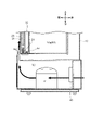
- Vertical partial sectional view of cold storage Longitudinal cross-sectional view showing the cooling area in the cold insulation chamber
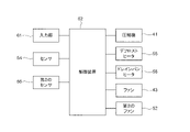
- Cooler block diagram Flowchart of the program executed by the controller
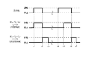
- Flowchart of the program executed by the controller Flowchart of the program executed by the controller Time chart showing operation of drain pan
- the side on which the sliding door 30 is arranged is defined as the front side of the cold storage box 1, and the opposite side is defined as the rear side of the cold storage box 1, as indicated by the arrow in FIG.
- the left side and the right side of the cold storage box 1 when viewed from the front are defined as the left side and the right side of the cold storage box 1, respectively.
- the side away from the surface on which the cold storage 1 is installed is the upper side of the cold storage 1, and the opposite side is the lower side of the cold storage 1.
- the cool box 1 is a chemical cool box that stores drugs at low temperatures.
- the cold storage 1 may be a blood cold storage or a thermostat.
- the cold storage 1 includes a box 10, a frame 20 and a sliding door 30, as shown in FIGS.
- the box 10 has an opening H1 on the front surface that opens when the sliding door 30 moves.
- a heat insulating material is filled between the outer surface and the inner surface of the box 10 .
- a space surrounded by the inner surface of the box 10 is a cold storage chamber R1, which is a space for storing medicine (FIGS. 3 and 4).
- the frame 20 is provided on the box 10 so as to border the opening H1.
- the frame 20 is provided with an outer rail 21 and an inner rail 22 extending in the left-right direction on the bottom surface of the frame 20 .
- the inner rail 22 is arranged behind the outer rail 21 (on the cold insulation chamber R1 side) ( FIG. 3 ).
- a sliding door 30 is attached to the frame body 20 .
- the sliding door 30 has a first sliding door 31 and a second sliding door 32.
- the first sliding door 31 is attached movably along the outer rail 21 .
- the first sliding door 31 is positioned on the right side of the frame 20 in the closed state.
- a second sliding door 32 is mounted movably along the inner rail 22 .
- the second sliding door 32 is positioned on the left side of the frame 20 in the closed state. The movement of the first sliding door 31 and the second sliding door 32 opens and closes the opening H1 and thus the cold storage compartment R1.
- the second sliding door 32 Since the first sliding door 31 is arranged on the outer rail 21 and the second sliding door 32 is arranged on the inner rail 22, the second sliding door 32 is positioned closer to the cooling chamber R1 than the first sliding door 31. . Therefore, the dew condensation generated on the second sliding door 32 is more than that generated on the first sliding door 31 .
- the box 10 has a machine room R2 below the cold insulation room R1 (Figs. 2 and 3).
- the machine room R2 has an air outlet H2.
- the air blowing port H2 is opened in front of the frame body 20 and is formed so that an air current, which will be described later, is blown against the sliding door 30. As shown in FIG.
- a compressor 41 and a condenser 42 which constitute a refrigeration circuit for cooling the inside of the cold storage room R1, and a fan 43 are arranged.
- the compressor 41 is arranged on the left side in the machine room R2. That is, the compressor 41 is arranged at a position closer to the second sliding door 32 closing the cold insulation chamber R1 than to the first sliding door 31 closing the cold insulation chamber R1.
- the condenser 42 is arranged approximately centrally in the machine room R2.
- the fan 43 is for generating airflow. Airflow is indicated by thick arrows in FIGS.
- the fan 43 rotates to take outside air into the machine room R2 and generate an airflow.
- the airflow passes around compressor 41 and condenser 42 .
- compressor 41 and condenser 42 are in operation, airflow passing around compressor 41 and condenser 42 is warmed by the temperature of compressor 41 and the temperature of condenser 42 .
- the airflow blows out from the blower port H2 and blows onto the sliding door 30.
- the heated airflow warms the sliding door 30, thereby suppressing condensation on the sliding door 30.
- the cold storage compartment R1 is partitioned by side walls 51 into a storage area R1a and a cooling area R1b.
- the storage area R1a is an area in which drugs and the like are stored.
- the cooling region R1b is a region where the air inside the cold storage chamber R1 is cooled.
- a second fan 52, an evaporator 53 constituting a refrigerating circuit, a sensor 54, a defrost heater 55, a second sensor 56, a drain pan 57 and a drain pan heater 58 are arranged at the rear upper end of the cold insulation compartment R1. It is A cooling region R1b is formed around the evaporator 53 .
- the second fan 52, the evaporator 53 forming the refrigerating circuit, the sensor 54, the defrost heater 55, the second sensor 56, the drain pan 57 and the drain pan heater 58 are arranged in the cooling region R1b. .
- the second fan 52 rotates to take the air in the storage area R1a into the cooling area R1b.
- the second fan 52 is arranged at the upper end of the cooling region R1b. Therefore, the second fan 52 takes in the air above the storage area R1a.
- the air taken into the cooling region R1b is blown out to the storage region R1a through an opening formed at the bottom of the cooling region R1b. That is, the air taken into the cooling region R1b flows downward from the upper end portion of the cooling region R1b as indicated by the arrows shown in FIG.
- the evaporator 53 cools the air taken into the cooling region R1b.
- the evaporator 53 is arranged below the second fan 52 .
- the evaporator 53 has a pipe 53a through which the refrigerant circulating in the refrigerating circuit flows, and fins 53b attached so as to come into contact with the pipe 53a.
- the sensor 54 detects the temperature inside the cold storage compartment R1.
- the sensor 54 is arranged above the evaporator 53 in the cooling region R1b. That is, the sensor 54 detects the temperature of the air taken into the cooling region R1b before it is cooled by the evaporator 53. That is, the temperature detected by the sensor 54 is equal to the temperature of the air in the storage area R1a.
- the defrost heater 55 is a heater that melts frost adhering to the piping 53a and the fins 53b by operating.
- the defrost heater 55 is, for example, a sheath heater and a cord heater.
- the defrost heater 55 is attached away from the pipe 53a of the evaporator 53 so as to be in contact with the fins 53b.
- An operation in which the defrost heater 55 is operated is particularly called a defrosting operation. A defrosting operation is performed while the compressor 41 is stopped.
- the second sensor 56 is a sensor that is separated from the pipe 53a and arranged to contact the fins 53b and detects the temperature of the fins 53b.
- the drain pan 57 receives water generated by the defrosting operation.
- the drain pan 57 is arranged below the evaporator 53 .
- the defrosting operation melts the frost adhering to the pipes 53a and the fins 53b to produce water. This water drops onto the drain pan 57 and is led out to the machine room R2 through a pipe (not shown).
- the drain pan heater 58 is a heater that heats the drain pan 57 .
- the drain pan heater 58 is, for example, a sheathed heater and a cord heater.
- the amount of heat generated by the drain pan heater 58 is smaller than the amount of heat generated by the defrost heater 55 .
- the drain pan heater 58 is attached so as to come into contact with the back surface of the drain pan 57 . Water received by the drain pan 57 may be cooled by the evaporator 53 and frozen. By operating the drain pan heater 58, even if the water received by the drain pan 57 freezes and ice is generated, the ice can be melted.
- the defrost heater 55 and the drain pan heater 58 are arranged in the cooling region R1b as described above. That is, the defrost heater 55 and the drain pan heater 58 are arranged in the cold insulation chamber R1.
- the cold storage 1 also includes an input unit 61 and a control device 62, as shown in FIG.
- the input unit 61 is for inputting the set temperature of the cold insulation chamber R1.
- the input unit 61 is, for example, a touch panel.
- the control device 62 is a computer that controls the refrigerator 1 in an integrated manner.
- the control device 62 includes a storage device that stores computer programs (hereinafter simply programs) and a processor that executes the computer programs.
- the control device 62 is electrically connected to the input section 61, the sensor 54, the second sensor 56, the compressor 41, the defrost heater 55, the drain pan heater 58, the fan 43 and the second fan 52.
- the control device 62 acquires the set temperature, the temperature detected by the sensor 54 and the temperature detected by the second sensor 56 that are input to the input unit 61 .
- the controller 62 controls the compressor 41, the defrost heater 55, the drain pan heater 58, the fan 43, and the second fan 52 based on the set temperature, the temperature detected by the sensor 54, and the temperature detected by the second sensor 56. .
- the control device 62 executes a program to control the compressor 41, thereby adjusting the temperature in the cold insulation compartment R1 to the set temperature. Specifically, the controller 62 repeats the operation and stoppage of the compressor 41 based on the set temperature and the temperature detected by the sensor 54 (FIG. 9). When the program is running, fan 43 and second fan 52 are controlled to rotate continuously.
- FIG. 6 At the start of the program, the drain pan heater 58 is off. Moreover, when the program is being executed, the operation and stop of the compressor 41 are repeated.
- the control device 62 determines whether or not the set temperature obtained from the input unit 61 is equal to or lower than a predetermined temperature.
- the predetermined temperature is, for example, 3° C., at which dew condensation occurs on the sliding door 30 when the temperature of the cold storage chamber R1 reaches the predetermined temperature.
- the predetermined temperature is set in advance in a program executed by the control device 62 when the cold storage 1 is manufactured. If the set temperature is equal to or lower than the predetermined temperature (S10: YES), the controller 62 executes synchronous control, which will be described later, in S11.
- control device 62 executes asynchronous control described later in S12.
- Synchronous control is control that operates the drain pan heater 58 when the compressor 41 is in operation.
- the controller 62 determines in S20 whether or not the compressor 41 is in operation. If the compressor 41 is stopped (S20: NO), the controller 62 repeatedly executes S20.
- the controller 62 determines in S21 that the temperature detected by the sensor 54 is a temperature obtained by adding a predetermined value to the set temperature (hereinafter referred to as added temperature). ) is determined as follows.
- the predetermined value is a value at which dew condensation occurring on the sliding door 30 is relatively small when the temperature of the cold insulation chamber R1 reaches the additional temperature regardless of the set temperature.
- the predetermined value is a constant value regardless of the set temperature, and is set in advance in a program executed by the control device 62 when the cold storage 1 is manufactured.
- the predetermined value is 5, for example.
- the controller 62 executes the program without operating the drain pan heater 58. Return to S20.
- the controller 62 When the temperature in the cold insulation chamber R1 decreases due to the compressor 41 being in operation and the temperature detected by the sensor 54 becomes equal to or lower than the addition temperature (S21: YES), the controller 62 The drain pan heater 58 is activated.
- control device 62 determines whether or not the compressor 41 has stopped in S23.
- the controller 62 repeatedly executes S23.
- the controller 62 stops the drain pan heater 58 in S24 and restarts the program in S20. back to
- Asynchronous control is control in which the operation of the compressor 41 and the operation of the drain pan heater 58 are not synchronized.
- the controller 62 determines in S30 whether or not the operating state of the compressor 41 has stopped. When the operating state of the compressor 41 continues (S30: NO), the controller 62 repeatedly executes S30.
- the controller 62 operates the drain pan heater 58 in S31, The defrosting operation, specifically, the operation of the defrost heater 55 is started. The defrosting operation continues until the temperature detected by the second sensor 56 reaches the second predetermined temperature.
- the control device 62 determines whether or not the temperature detected by the second sensor 56 is equal to or higher than the third predetermined temperature.
- the third predetermined temperature is a threshold for stopping operation of the drain pan heater 58 .
- the third predetermined temperature is a temperature higher than the second predetermined temperature.
- the second predetermined temperature and the third predetermined temperature are set in advance in a program executed by the control device 62 when the cold storage 1 is manufactured.
- the control device 62 When the temperature detected by the second sensor 56 is lower than the third predetermined temperature (S32: NO), the control device 62 repeatedly executes S32.
- the control device 62 stops the drain pan heater 58 in S33 and returns the program to S30.
- the temperature in the cold storage chamber R1 when the temperature detected by the second sensor 56 reaches the third predetermined temperature is lower than the temperature that may adversely affect the chemicals stored in the cold storage chamber R1.
- the temperature is sufficiently low.
- the drain pan heater 58 heats the air cooled by the evaporator 53 because it is arranged in the cold insulation compartment R1. That is, the drain pan heater 58 operates to suppress cooling by the refrigeration circuit. Therefore, when the drain pan heater 58 is operating, the time required for the temperature in the cold insulation chamber R1 to reach the set temperature is longer than when the drain pan heater 58 is not operating. That is, the operating time of the compressor 41 when the drain pan heater 58 is operating is longer than the operating time of the compressor 41 when the drain pan heater 58 is stopped.
- the temperature of the compressor 41 increases as the operating time of the compressor 41 increases. Along with this, the temperature of the airflow passing around the compressor 41 rises. That is, the temperature of the airflow when the drain pan heater 58 is operating is higher than the temperature of the airflow when the drain pan heater 58 is stopped. Therefore, when the set temperature is set to a predetermined temperature or lower at which dew condensation occurs relatively on the sliding door 30, the temperature of the airflow can be increased, thereby suppressing the occurrence of dew condensation.
- the compressor 41 is arranged closer to the second sliding door 32 closing the cold insulation chamber R1 than to the first sliding door 31 closing the cold insulation chamber R1. Therefore, the temperature of the airflow blown onto the second sliding door 32 can be made higher than the temperature of the airflow blown onto the first sliding door 31 . Further, as described above, the dew condensation generated on the second sliding door 32 is larger than the dew condensation generated on the first sliding door 31 . In other words, dew condensation occurring on the second sliding door 32 can be effectively suppressed by arranging the compressor 41 .
- the detected temperature of the sensor 54 is higher than the addition temperature. If so (S21: NO), the drain pan heater 58 does not operate.
- the temperature detected by the sensor 54 is higher than the added temperature, the difference between the temperature in the cold insulation chamber R1 and the set temperature is relatively large, so that the drain pan heater 58 is controlled so as not to operate in order to give priority to cooling by the refrigeration circuit. be done.
- the detected temperature of the sensor 54 is higher than the added temperature, for example, the user opens the sliding door 30, causing outside air to flow into the cold insulation chamber R1 and the temperature inside the cold insulation chamber R1 to rise. be.
- the temperature detected by the sensor 54 is higher than the added temperature, the amount of dew condensation generated on the sliding door 30 is relatively small as described above. can be sufficiently suppressed.
- the drain pan heater 58 operates (S22, time t5). Then, when the temperature in the cold insulation chamber R1 further drops and reaches the set temperature and the compressor 41 stops (S23: YES, time t6), the drain pan heater 58 stops (S24).
- the drain pan heater 58 When the set temperature is higher than the predetermined temperature (S10: NO) and the compressor 41 starts operating (S30: NO) (time t1), the drain pan heater 58 does not operate. Therefore, the temperature of the airflow blown onto the sliding door 30 is lower than the temperature of the airflow when the drain pan heater 58 is operating. However, when the set temperature is higher than the predetermined temperature, the dew condensation generated on the sliding door 30 is less than that generated on the sliding door 30 when the set temperature is equal to or lower than the predetermined temperature. be.
- the drain pan heater 58 starts operating when the operation of the compressor 41 stops (time t6), and stops when the temperature detected by the second sensor 56 reaches or exceeds the third predetermined temperature ( Time t7) is repeatedly executed.
- the drain pan heater 58 may operate regardless of the added temperature.
- S21 is not executed in the flowchart shown in FIG. That is, the control device 62 operates the drain pan heater 58 when the condition that the set temperature of the cold insulation chamber R1 is equal to or lower than the predetermined temperature and the condition that the compressor 41 is in the operating state are satisfied.
- the compressor 41 may be arranged in the center of the machine room R2 or at a position closer to the first sliding door 31 closing the cold storage chamber R1 than the second sliding door 32 closing the cold storage chamber R1.
- the defrost heater 55 may operate instead of the drain pan heater 58 when the compressor 41 is in operation.
- the present disclosure can be widely used for medical coolers, blood coolers, and coolers such as thermostats.
Landscapes
- Engineering & Computer Science (AREA)
- Physics & Mathematics (AREA)
- Thermal Sciences (AREA)
- Mechanical Engineering (AREA)
- General Engineering & Computer Science (AREA)
- Chemical & Material Sciences (AREA)
- Combustion & Propulsion (AREA)
- Removal Of Water From Condensation And Defrosting (AREA)
- Devices That Are Associated With Refrigeration Equipment (AREA)
- Defrosting Systems (AREA)
Priority Applications (4)
| Application Number | Priority Date | Filing Date | Title |
|---|---|---|---|
| CN202280015897.8A CN116868018A (zh) | 2021-03-17 | 2022-02-04 | 冷库 |
| EP22770930.0A EP4269917A4 (en) | 2021-03-17 | 2022-02-04 | COLD STORAGE UNIT |
| JP2023506851A JP7478307B2 (ja) | 2021-03-17 | 2022-02-04 | 保冷庫 |
| US18/365,733 US12416441B2 (en) | 2021-03-17 | 2023-08-04 | Cold storage |
Applications Claiming Priority (2)
| Application Number | Priority Date | Filing Date | Title |
|---|---|---|---|
| JP2021-043838 | 2021-03-17 | ||
| JP2021043838 | 2021-03-17 |
Related Child Applications (1)
| Application Number | Title | Priority Date | Filing Date |
|---|---|---|---|
| US18/365,733 Continuation US12416441B2 (en) | 2021-03-17 | 2023-08-04 | Cold storage |
Publications (1)
| Publication Number | Publication Date |
|---|---|
| WO2022196170A1 true WO2022196170A1 (ja) | 2022-09-22 |
Family
ID=83322227
Family Applications (1)
| Application Number | Title | Priority Date | Filing Date |
|---|---|---|---|
| PCT/JP2022/004485 Ceased WO2022196170A1 (ja) | 2021-03-17 | 2022-02-04 | 保冷庫 |
Country Status (5)
| Country | Link |
|---|---|
| US (1) | US12416441B2 (https=) |
| EP (1) | EP4269917A4 (https=) |
| JP (1) | JP7478307B2 (https=) |
| CN (1) | CN116868018A (https=) |
| WO (1) | WO2022196170A1 (https=) |
Citations (6)
| Publication number | Priority date | Publication date | Assignee | Title |
|---|---|---|---|---|
| JPH06159904A (ja) * | 1992-11-27 | 1994-06-07 | Sanyo Electric Co Ltd | 低温ショーケース |
| JP2000088438A (ja) | 1998-09-09 | 2000-03-31 | Sanyo Electric Co Ltd | 冷却貯蔵庫 |
| WO2006118217A1 (ja) * | 2005-04-27 | 2006-11-09 | Fukushima Kogyo Co., Ltd. | 冷却庫 |
| JP2017020745A (ja) * | 2015-07-14 | 2017-01-26 | ホシザキ株式会社 | 冷却貯蔵庫 |
| WO2021039446A1 (ja) * | 2019-08-28 | 2021-03-04 | Phc株式会社 | 保冷庫 |
| JP2021043838A (ja) | 2019-09-13 | 2021-03-18 | パイオニア株式会社 | 情報処理装置、制御方法、プログラム及び記憶媒体 |
Family Cites Families (9)
| Publication number | Priority date | Publication date | Assignee | Title |
|---|---|---|---|---|
| JPH0693856B2 (ja) * | 1989-04-19 | 1994-11-24 | 三洋電機株式会社 | ショーケース |
| US4977754A (en) * | 1990-05-01 | 1990-12-18 | Specialty Equipment Companies, Inc. | Next-to-be-purchased cold beverage merchandiser |
| JP3190793B2 (ja) * | 1994-09-08 | 2001-07-23 | ホシザキ電機株式会社 | 冷却貯蔵庫の庫内温度制御装置 |
| JP2000329445A (ja) * | 1999-05-20 | 2000-11-30 | Hoshizaki Electric Co Ltd | 低温貯蔵庫 |
| JP4229555B2 (ja) * | 1999-12-17 | 2009-02-25 | 福島工業株式会社 | 温度調節機能付き保管庫 |
| JP4036597B2 (ja) * | 2000-03-08 | 2008-01-23 | 三洋電機株式会社 | 低温ショーケース |
| JP2005164199A (ja) * | 2003-12-05 | 2005-06-23 | Matsushita Electric Ind Co Ltd | 冷蔵庫 |
| JP5713536B2 (ja) * | 2009-01-05 | 2015-05-07 | 三菱電機株式会社 | ヒートポンプ式給湯器 |
| CN209926609U (zh) * | 2018-12-21 | 2020-01-10 | 青岛经济技术开发区海尔热水器有限公司 | 一种接水盘除冰装置及应用该装置的热泵热水器 |
-
2022
- 2022-02-04 EP EP22770930.0A patent/EP4269917A4/en active Pending
- 2022-02-04 CN CN202280015897.8A patent/CN116868018A/zh active Pending
- 2022-02-04 JP JP2023506851A patent/JP7478307B2/ja active Active
- 2022-02-04 WO PCT/JP2022/004485 patent/WO2022196170A1/ja not_active Ceased
-
2023
- 2023-08-04 US US18/365,733 patent/US12416441B2/en active Active
Patent Citations (6)
| Publication number | Priority date | Publication date | Assignee | Title |
|---|---|---|---|---|
| JPH06159904A (ja) * | 1992-11-27 | 1994-06-07 | Sanyo Electric Co Ltd | 低温ショーケース |
| JP2000088438A (ja) | 1998-09-09 | 2000-03-31 | Sanyo Electric Co Ltd | 冷却貯蔵庫 |
| WO2006118217A1 (ja) * | 2005-04-27 | 2006-11-09 | Fukushima Kogyo Co., Ltd. | 冷却庫 |
| JP2017020745A (ja) * | 2015-07-14 | 2017-01-26 | ホシザキ株式会社 | 冷却貯蔵庫 |
| WO2021039446A1 (ja) * | 2019-08-28 | 2021-03-04 | Phc株式会社 | 保冷庫 |
| JP2021043838A (ja) | 2019-09-13 | 2021-03-18 | パイオニア株式会社 | 情報処理装置、制御方法、プログラム及び記憶媒体 |
Non-Patent Citations (1)
| Title |
|---|
| See also references of EP4269917A4 |
Also Published As
| Publication number | Publication date |
|---|---|
| US12416441B2 (en) | 2025-09-16 |
| EP4269917A1 (en) | 2023-11-01 |
| CN116868018A (zh) | 2023-10-10 |
| EP4269917A4 (en) | 2024-05-29 |
| JP7478307B2 (ja) | 2024-05-02 |
| JPWO2022196170A1 (https=) | 2022-09-22 |
| US20240019192A1 (en) | 2024-01-18 |
Similar Documents
| Publication | Publication Date | Title |
|---|---|---|
| KR101260277B1 (ko) | 냉장고 | |
| CN102374722B (zh) | 冰箱 | |
| JP6131116B2 (ja) | 冷蔵庫 | |
| JP5507511B2 (ja) | 冷蔵庫 | |
| KR101284056B1 (ko) | 냉장고 | |
| JP2013061089A (ja) | 冷蔵庫 | |
| JP6422513B2 (ja) | 冷凍冷蔵庫 | |
| JP2017072336A (ja) | 冷蔵庫 | |
| JP6309710B2 (ja) | 冷凍冷蔵庫 | |
| JP5838238B2 (ja) | 冷蔵庫 | |
| WO2018103652A1 (zh) | 冰箱 | |
| KR101152070B1 (ko) | 냉장고 | |
| JP7536468B2 (ja) | 冷却庫 | |
| WO2022196170A1 (ja) | 保冷庫 | |
| KR100701955B1 (ko) | 냉장고의 해동실유닛 제어방법 | |
| US10161666B2 (en) | Cool air path damper assembly with elastic anti-freezing member | |
| JP5039761B2 (ja) | 冷蔵庫 | |
| WO2022196171A1 (ja) | 保冷庫 | |
| JP6695199B2 (ja) | 冷却貯蔵庫 | |
| CN112262289B (zh) | 冰箱 | |
| CN114484988A (zh) | 冰箱 | |
| JP6282255B2 (ja) | 冷蔵庫 | |
| JP2025079047A (ja) | 冷蔵庫 | |
| WO2023030186A1 (zh) | 冰箱 | |
| JP2019203633A (ja) | 冷却貯蔵庫 |
Legal Events
| Date | Code | Title | Description |
|---|---|---|---|
| 121 | Ep: the epo has been informed by wipo that ep was designated in this application |
Ref document number: 22770930 Country of ref document: EP Kind code of ref document: A1 |
|
| ENP | Entry into the national phase |
Ref document number: 2023506851 Country of ref document: JP Kind code of ref document: A |
|
| ENP | Entry into the national phase |
Ref document number: 2022770930 Country of ref document: EP Effective date: 20230725 |
|
| WWE | Wipo information: entry into national phase |
Ref document number: 202280015897.8 Country of ref document: CN |
|
| NENP | Non-entry into the national phase |
Ref country code: DE |