WO2022196151A1 - 循環用送液蓋、印刷装置およびインク循環方法 - Google Patents
循環用送液蓋、印刷装置およびインク循環方法 Download PDFInfo
- Publication number
- WO2022196151A1 WO2022196151A1 PCT/JP2022/004011 JP2022004011W WO2022196151A1 WO 2022196151 A1 WO2022196151 A1 WO 2022196151A1 JP 2022004011 W JP2022004011 W JP 2022004011W WO 2022196151 A1 WO2022196151 A1 WO 2022196151A1
- Authority
- WO
- WIPO (PCT)
- Prior art keywords
- ink
- tank
- connection port
- lid
- circulation
- Prior art date
- Legal status (The legal status is an assumption and is not a legal conclusion. Google has not performed a legal analysis and makes no representation as to the accuracy of the status listed.)
- Ceased
Links
Images




Classifications
-
- B—PERFORMING OPERATIONS; TRANSPORTING
- B41—PRINTING; LINING MACHINES; TYPEWRITERS; STAMPS
- B41J—TYPEWRITERS; SELECTIVE PRINTING MECHANISMS, i.e. MECHANISMS PRINTING OTHERWISE THAN FROM A FORME; CORRECTION OF TYPOGRAPHICAL ERRORS
- B41J2/00—Typewriters or selective printing mechanisms characterised by the printing or marking process for which they are designed
- B41J2/005—Typewriters or selective printing mechanisms characterised by the printing or marking process for which they are designed characterised by bringing liquid or particles selectively into contact with a printing material
- B41J2/01—Ink jet
- B41J2/17—Ink jet characterised by ink handling
- B41J2/175—Ink supply systems ; Circuit parts therefor
-
- B—PERFORMING OPERATIONS; TRANSPORTING
- B41—PRINTING; LINING MACHINES; TYPEWRITERS; STAMPS
- B41J—TYPEWRITERS; SELECTIVE PRINTING MECHANISMS, i.e. MECHANISMS PRINTING OTHERWISE THAN FROM A FORME; CORRECTION OF TYPOGRAPHICAL ERRORS
- B41J2/00—Typewriters or selective printing mechanisms characterised by the printing or marking process for which they are designed
- B41J2/005—Typewriters or selective printing mechanisms characterised by the printing or marking process for which they are designed characterised by bringing liquid or particles selectively into contact with a printing material
- B41J2/01—Ink jet
- B41J2/17—Ink jet characterised by ink handling
- B41J2/18—Ink recirculation systems
Definitions
- This invention relates to a technique for circulating ink by collecting the ink discharged from one tank into the other tank.
- ink is replenished to the printing device as appropriate.
- Such ink replenishment can be performed by, for example, installing a tank for storing ink in the printing apparatus.
- some printers have built-in tanks in addition to ink replenishment tanks, and ink is circulated between these tanks for various purposes.
- ink is circulated between the main tank and the sub-tank in order to make the print quality uniform before and after the main tank is replenished with ink.
- Ink circulation may also be performed for the purpose of suppressing sedimentation of ink components.
- the ink discharged from the main tank can also be circulated by collecting the ink in the main tank without going through the sub-tank.
- a tank having two openings can be used as a tank mounted for ink replenishment.
- the ink can be circulated by discharging the ink from one opening and recovering the ink to the other opening.
- one of the two openings can be used for ink circulation.
- one opening may be used to insert a stirring rod into the tank to stir the ink in the tank.
- the present invention has been made in view of the above problems, and enables the circulation of ink for recovering the ink discharged from one tank to the other tank using only one opening provided in one of the tanks.
- the purpose is to
- a liquid-feeding lid for circulation is a liquid-feeding lid for circulation attached to an opening of one tank in order to feed ink from one tank storing ink to the other tank, wherein the opening of the one tank a first connection port provided in the lid body to which an insertion tube inserted into one tank to guide ink from one tank to the other tank is connected; a second connection port provided in the lid body to which an introduction pipe for guiding ink toward one of the tanks is connected, and the lid body flowed out from the introduction pipe attached to the second connection port. It has a channel for guiding ink to the outer wall of the insertion tube connected to the first connection port, and the ink guided by the channel and reaching the outer wall flows into one of the tanks via the outer wall.
- a printing apparatus includes a tank that stores ink supplied from one tank that stores ink, an ejection head that ejects ink that is supplied from the other tank, and an ejection head that is attached to an opening of one of the tanks.
- the circulating liquid feed lid includes a lid body covering the opening of one of the tanks, and an inner portion of the lid for guiding the ink from one tank to the other tank.
- a first connection port provided on the lid body to which an insertion tube to be inserted is connected, and a second connection provided on the lid body to which an introduction pipe for guiding ink toward one of the tanks is connected.
- the lid body has a channel for guiding ink flowing out from the introduction tube attached to the second connection port to the outer wall of the insertion tube connected to the first connection port, The ink that is guided by and reaches the outer wall flows into one of the tanks through the outer wall.
- An ink circulation method is an ink circulation method for circulating ink by recovering ink discharged from one tank that stores ink into the other tank, and includes a lid body that covers the opening of the one tank. a step of guiding the ink discharged from one of the tanks by an insertion pipe connected to a first connection port provided in the lid body; a step of guiding the ink toward the outer wall of the insertion tube connected to the first connection port, the flow path provided in the lid body guiding the ink flowing out from the introduction tube attached to the second connection port to the outer wall of the insertion tube connected to the first connection port; and a step in which the ink guided by the flow path and reaches the outer wall flows into one of the tanks via the outer wall, and the ink discharged from the one tank via the insertion tube is introduced into the It reaches the outer wall via pipes and channels and is collected in one of the tanks.
- liquid feed lid for circulation in order to feed ink from one tank to the other tank, the liquid feed lid for circulation is attached to the opening of one of the tanks. It is attached.
- This liquid supply lid for circulation includes a lid body that covers the opening of one of the tanks, and this lid body has first and second connection ports.
- the first connection port is connected to an insertion tube that is inserted into one tank to guide ink from one tank to the other tank. That is, the first connection port functions as a port for supplying ink from one tank to the other tank.
- an introduction pipe that guides the ink toward one of the tanks is connected to the second connection port.
- the second connection port functions as an ink recovery port that recovers the ink discharged from one of the tanks through the first connection port to the other tank.
- the lid body has a channel for guiding ink flowing out from the introduction tube attached to the second connection port to the outer wall of the insertion tube connected to the first connection port, The ink that reaches the outer wall flows into one of the tanks through the outer wall. In this way, ink is collected into one tank by utilizing the outer wall of the insertion tube for supplying ink from one tank to the other tank. Therefore, it is possible to circulate ink by collecting ink discharged from one tank into the other tank using only one opening provided in one of the tanks.
- the ink flows into one of the tanks through the outer wall of the insertion tube.
- the ink flows down along the outer wall of the insertion tube, so the ink stored in one of the tanks flows down at a relatively gentle speed. Therefore, it is also possible to achieve the effect of suppressing bubbling caused by ink flowing down.
- the first connection port has an insertion hole into which the insertion tube is inserted, and the first connection port is configured such that the insertion tube inserted into the insertion hole protrudes from the lid body into one of the tanks.
- a liquid supply lid for circulation may be configured to support the insertion hole.
- the channel has an inlet into which ink flows from the introduction pipe, and an outlet provided below the inlet and communicating with the insertion hole.
- the circulating liquid feeding lid may be configured so that the liquid flows down to one of the tanks through the gap between the outer wall of the insertion tube and the insertion hole. With such a configuration, the flow path communicating with the insertion hole allows the ink to reach the outer wall of the insertion tube inserted into the insertion hole accurately.
- the circulation liquid feeding lid may be configured such that the channel is inclined with respect to the vertical direction from the inflow port to the outflow port. With such a configuration, the speed of ink flowing through the flow path can be suppressed. Therefore, the ink that has flowed down to the outflow port flows along the outer wall of the insertion tube to the ink stored in one of the tanks at a relatively slow speed, and the above-described bubbling of the ink can be effectively suppressed. .
- the lid body may constitute a liquid supply lid for circulation so as to be detachably attached to the opening of one of the tanks.
- a liquid supply lid for circulation so as to be detachably attached to the opening of one of the tanks.
- the liquid supply lid for circulation may be configured so as to include an insertion tube connected to the first connection port.
- the liquid feeding lid for circulation is provided with the insertion tube, there is no need to separately prepare the insertion tube, and the workability of the operator can be improved.
- the insertion tube has a flange
- the first connection port has a step with which the flange engages
- the insertion tube is supported by the first connection port by engaging the flange with the step.
- a liquid feeding lid for circulation may be configured. With such a configuration, the first connection port can support the insertion tube using a simple configuration such as engaging the flange with the step.
- a discharge pipe connected to the first connection port and communicating with the insertion pipe is provided, and the discharge pipe discharges ink flowing out from one tank through the insertion pipe toward the other tank.
- a liquid feeding lid for circulation may be configured. In such a configuration, since the liquid feeding cover for circulation is provided with the discharge pipe, there is no need to separately prepare the discharge pipe, and the workability of the operator can be improved.
- the circulation liquid feeding lid may be configured so as to include an introduction tube attached to the second connection port.
- FIG. 1 is a front view schematically showing an example of a printing system equipped with a printing apparatus according to a first embodiment of the present invention
- FIG. FIG. 4 is a schematic diagram showing the configuration of an ink supply mechanism for white.
- FIG. 2 is a schematic diagram showing the configuration of a color ink supply mechanism;
- FIG. 2 is a perspective view schematically showing the structure of a drum tank;
- FIG. 4 is a partial cross-sectional view schematically showing the overall configuration of the circulation liquid-feeding lid.
- FIG. 4 is a cross-sectional view schematically showing the configuration of the lid body of the circulation liquid feeding lid.
- FIG. 4 is a plan view schematically showing the configuration of the lid body of the circulation liquid feeding lid.
- FIG. 4 is a plan view schematically showing the configuration of the lid body of the circulation liquid feeding lid.
- FIG. 4 is a front view schematically showing the configuration of a discharge pipe provided in the circulation liquid feeding lid for discharging ink from the drum tank.
- FIG. 4 is a front view schematically showing the structure of an insertion tube included in the liquid feeding cover for circulation for discharging ink from the drum tank.
- FIG. 4 is a front view schematically showing the configuration of an introduction pipe provided in a circulation liquid feeding lid for collecting ink in a drum tank.
- FIG. 1 is a front view schematically showing a printing system equipped with an example of the printing apparatus according to the present invention.
- the X direction which is the horizontal direction in which the coating device 2, the printing device 3, and the drying device 4 constituting the printing system 1 are arranged, is shown.
- the horizontal direction Y and the vertical direction Z are shown as appropriate.
- the printing system 1 conveys the long belt-shaped print medium M from the delivery roll 11 to the take-up roll 12 in a roll-to-roll manner, while applying the coating process, the printing process, and the drying process to the print medium M. That is, the coating device 2 applies the coating liquid to the printing medium M. As shown in FIG. Then, the printing device 3 applies various inks to the printing medium M by an inkjet method to print an image. Furthermore, the drying device 4 dries the ink adhering to the print medium M.
- the material of the print medium M is a film such as OPP (oriented polypropylene) or PET (polyethylene terephthalate). However, the material of the print medium M is not limited to film, and may be paper or the like.
- Such a print medium M has flexibility. Further, hereinafter, of the two surfaces of the printing medium M, the recording surface on which an image is printed is referred to as a surface M1, and the surface opposite to the surface M1 is referred to as a back surface M2.
- the coating device 2 has a pan 21 that stores a liquid primer (coating liquid), a gravure roller 22 that is partially immersed in the primer stored in the pan 21, and a transport section 23 that transports the print medium M.
- a coating area is provided in which the gravure roller 22 contacts the print medium M transported by the transport unit 23 from below.
- the print medium M is conveyed along the .
- the gravure roller 22 supplies the primer to the application area by rotating while holding the primer on its peripheral surface.
- the primer supplied by the gravure roller 22 is applied to the surface M1 of the print medium M in the application area.
- the traveling direction of the print medium M is opposite to the rotating direction of the peripheral surface of the gravure roller 22 .
- the primer is applied to the print medium M by a so-called reverse kiss method.
- the conveying unit 23 conveys the printing medium M from the coating device 2 to the printing device 3 while directing the surface M1 of the printing medium M coated with the primer upward.
- the printing device 3 includes a housing 31, a color printing unit 32 arranged in the housing 31, a white printing unit 33 arranged above the color printing unit 32 in the housing 31, and A transport unit 34 transports the print medium M by a plurality of rollers arranged.
- the color printing section 32 has a plurality (4 to 6) of head sections 321 arranged in the traveling direction of the printing medium M above the printing medium M conveyed by the conveying section 34 .
- Each head unit 321 has a plurality of ejection heads, and ejects color inks of different colors from the nozzles of the ejection heads facing from above onto the surface M1 of the print medium M passing below by an inkjet method. Further, a color ink supply mechanism for supplying color ink to the ejection head of the head section 321 for each color is provided.
- color ink means ink other than white, and includes ink such as cyan, magenta, yellow, and black.
- the white printing section 33 has a single head section 331 arranged above the print medium M conveyed by the conveying section 34 .
- the head unit 331 has a plurality of ejection heads, and ejects white ink from the nozzles of the ejection heads facing from above to the surface M1 of the print medium M passing below each by an inkjet method.
- a white ink supply mechanism for supplying white ink to the ejection heads of the head section 331 is provided. That is, while white ink is being supplied to the ejection head of the head section 331 by the ink supply mechanism, a white image is printed on the surface M1 of the print medium M by the white ink ejected from the ejection head.
- the configuration and operation of the ink supply mechanism will be detailed later.
- the drying device 4 dries the ink adhering to the surface M1 of the printing medium M conveyed from the printing device 3.
- the drying device 4 has a housing 41 (drying furnace).
- rollers 42, 43, and 46 are arranged on one side in the X direction, and air turn bars 44 and 45 are arranged on the other side in the X direction.
- a substantially S-shaped transport path is formed when viewed from the Y direction, and the print medium M is transported along the transport path. Ink adhering to the surface M1 of the print medium M during this transport is dried. Then, the print medium M that has undergone the drying process is carried out from the drying device 4 and wound up on the winding roll 12 .
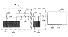
- FIG. 2A is a schematic diagram showing the configuration of the white ink supply mechanism
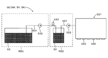
- FIG. 2B is a schematic diagram showing the configuration of the color ink supply mechanism.
- the ink supply mechanism 5W that supplies white ink and the ink supply mechanisms 5C, 5M, 5Y, and 5K that supply cyan, magenta, yellow, and black inks will be described.
- the ink supply mechanism 5W and the ink supply mechanisms 5C, 5M, 5Y and 5K are mostly common. Therefore, the ink supply mechanism 5W will be described first, and then the ink supply mechanism 5C will be described. Also, since the ink supply mechanisms 5C, 5M, 5Y, and 5K have the same configuration, the description of the ink supply mechanisms 5M, 5Y, and 5K is omitted.
- the ink supply mechanism 5W has a buffer tank 52 arranged in the buffer area R52 and a drum tank 53 arranged in the storage area R53, and ink is stored in each of the buffer tank 52 and the drum tank 53.
- the buffer area R52 and the storage area R53 are provided at different positions in the housing of the printing device 3, respectively.
- the inks stored in the buffer tank 52 and the drum tank 53 are indicated by dot hatching.
- the ink supply mechanism 5W has a pipe 521 connecting the buffer tank 52 and the head portion 331, and a pump 522 attached to the pipe 521 between the buffer tank 52 and the head portion 331. Ink is supplied from the buffer tank 52 to the head portion 331 through the pipe 521 by the operation.
- the head unit 331 has a plurality of ejection heads 332, and ejects the ink supplied from the buffer tank 52 by the ejection heads 332 by an inkjet method.
- the ink supply mechanism 5W has a pipe 531 (supply pipe) connecting the drum tank 53 and the buffer tank 52, and a pump 532 attached to the pipe 531 between the drum tank 53 and the buffer tank 52. , the ink is supplied from the drum tank 53 to the buffer tank 52 through the pipe 531 by operating the pump 532 .
- the ink supply mechanism 5W also has a valve 533 attached to the pipe 531 between the pump 532 and the buffer tank 52. Therefore, the ink supply mechanism 5W opens the valve 533 to allow ink to be supplied from the drum tank 53 to the buffer tank 52, and closes the valve 533 to allow ink to flow from the drum tank 53 to the buffer tank 52. Supply can be regulated.
- the ink supply mechanism 5W includes a pipe 534 (recovery pipe) connecting the drum tank 53 and the branch point J between the pump 532 and the valve 533, and a valve 535 attached to tubing 534 therebetween. That is, a pipe 534 to which a valve 535 is attached is provided in parallel with the pump 532 . Therefore, by operating the pump 532 with the valve 533 closed and the valve 535 open, ink can be recovered from the branch point J of the pipe 531 to the drum tank 53 via the pipe 534 (ink recovery operation). . Furthermore, in parallel with this ink recovery operation, ink is discharged from the drum tank 53 to the branch point J through the pipe 531 by the operation of the pump 532 . In other words, an ink circulation operation is performed in which the ink discharged from the drum tank 53 to the pipe 531 is recovered to the drum tank 53 through the pipe 534 .
- a pipe 534 recovery pipe
- the valve 535 is closed, thereby regulating the recovery of the ink to the drum tank 53 via the pipe 534 .
- ink is smoothly supplied from the drum tank 53 to the buffer tank 52 .
- the ink supply mechanism 5W also has a rod-shaped stirring member 537 inserted into the drum tank 53 and a stirring motor 538 that rotates the stirring member 537 .
- the lower end of the agitating member 537 is immersed in the ink stored in the drum tank 53, and when the agitating motor 538 rotates the agitating member 537, the agitating blade provided at the lower end of the agitating member 537 rotates to squirt the ink. Stir (stir action). This stirring operation is executed in parallel with the ink supply operation and the ink recovery operation.
- the ink supply mechanism 5C differs from the ink supply mechanism 5W described above in that it does not have a pipe 534, a valve 535, a stirring member 537, and a stirring motor 538, and other points are common to the ink supply mechanism 5W. That is, the ink supply mechanism 5C supplies ink from the buffer tank 52 to the head section 321, and the head section 321 ejects the ink supplied from the ink supply mechanism 5C by the ejection head 322 by an inkjet method. Further, as the amount of ink stored in the buffer tank 52 decreases, the ink supply mechanism 5C supplies ink from the drum tank 53 to the buffer tank 52 (ink supply operation). The same applies to the ink supply mechanisms 5M, 5Y and 5K.
- FIG. 3 is a perspective view schematically showing the configuration of the drum tank.
- the drum tank 53 has a cylindrical drum body Ta, and stores ink inside the drum body Ta. Further, the drum body Ta has two openings Tb and Tc on its upper surface. Both of these openings Tb and Tc have a circular shape.
- ink supply mechanisms 5C, 5M, 5Y, and 5K ink is discharged from the drum body Ta to the pipe 531 through one of the two openings Tb and Tc (for example, the opening Tb).
- ink is discharged from the drum main body Ta to the pipe 531 and from the pipe 534 to the drum main body Ta through one of the two openings Tb and Tc (for example, the opening Tb).
- Ink recovery is performed, and the stirring member 537 is inserted into the drum main body Ta via the other (for example, the opening Tc).
- the present embodiment is provided with a liquid supply cover for circulation, which will be described below.
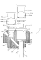
- FIG. 4 is a partial cross-sectional view schematically showing the overall configuration of the circulation liquid-feeding lid, and FIG. 4 shows the circulation liquid-feeding lid connected to the pipes 531 and 534 .
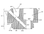
- FIG. 5 is a cross-sectional view schematically showing the configuration of the lid main body of the circulation liquid-feeding lid
- FIG. 6 is a plan view schematically showing the configuration of the lid main body of the circulation liquid-feeding lid.
- FIG. 7 is a front view schematically showing the configuration of a discharge pipe provided in the circulation liquid feed lid for discharging ink from the drum tank.
- FIG. 7 shows the discharge pipe connected to the pipe 531.
- FIG. 8 is a front view schematically showing the configuration of an insertion tube provided in the circulation liquid feeding cover for discharging ink from the drum tank.
- FIG. 9 is a front view schematically showing the configuration of an introduction pipe provided in the liquid supply lid for circulation for recovering the ink in the drum tank, and FIG.
- the lid body 61 included in the circulation liquid feeding lid 6 is attached to the opening Tb of the drum tank 53 to cover the opening Tb.
- the upper end portion of the lid body 61 constitutes a handle portion 611
- the lower end portion of the lid body 61 constitutes a fastening portion 612 .
- a cylindrical surface 611a is provided on at least a part of the side surface of the grip portion 611, and the operator grips the cylindrical surface 611a of the grip portion 611 with fingers to attach the lid body 61 to the drum tank 53, The lid body 61 can be removed from the drum tank 53 .
- the diameter of this cylindrical surface 611a is larger than the diameter of the opening Tb.
- a flange 612a is provided on a part of the side surface of the fastening portion 612, and a screw (bolt) is provided on the side surface of the flange 612a.
- a screw (nut) is provided for the opening Tb of the drum tank 53 . Therefore, the fastening portion 612 can be fastened to the drum tank 53 by screwing the bolt of the flange 612 a into the nut of the drum tank 53 while inserting the fastening portion 612 of the lid body 61 into the opening Tb.
- the handle portion 611 is positioned outside the drum tank 53 to cover the opening Tb of the drum tank 53, and the fastening portion 612 is positioned inside the drum tank 53.
- the lid body 61 has a discharge connection port 62 that vertically penetrates the lid body 61 . That is, the discharge connection port 62 opens to both the upper side and the lower side of the lid body 61 .
- the discharge connection port 62 includes a discharge pipe insertion hole 621 opening upward of the lid body 61, a flange housing hole 622 provided below the discharge pipe insertion hole 621, and a flange housing hole 622 provided below the flange housing hole 622. and an insertion hole 623 .
- Each of the discharge pipe insertion hole 621, the flange housing hole 622 and the insertion hole 623 has a cylindrical shape with a common center line and communicates with each other in the vertical direction.
- the diameter of the discharge pipe insertion hole 621 is slightly larger than the diameter of the flange storage hole 622 , and a step 624 is provided between the discharge pipe insertion hole 621 and the flange storage hole 622 .
- the diameter of the flange housing hole 622 is larger than the diameter of the insertion hole 623 , and a step 625 is provided between the flange housing hole 622 and the insertion hole 623 .
- the lid body 61 has an introduction connection port 63 .
- the introduction connection port 63 has an introduction pipe insertion hole 631 provided in the vertical direction, and the introduction pipe insertion hole 631 opens to the upper side of the lid body 61 .
- the introduction pipe insertion hole 631 is provided at a position higher than the insertion hole 623 .
- the lid body 61 has a communication hole 64 that communicates the introduction pipe insertion hole 631 of the introduction connection port 63 and the insertion hole 623 of the discharge connection port 62 .
- the communication hole 64 is a pipe extending straight from the introduction pipe insertion hole 631 toward the insertion hole 623 .
- the communication hole 64 is inclined with respect to the Z direction (vertical direction), and in this example, the acute angle between the communication hole 64 and the Z direction is 45 degrees.
- the magnitude of the acute angle between the communication hole 64 and the Z direction is not limited to this example, and may be 45 degrees or less or greater than 45 degrees.
- the communication hole 64 has an inlet 641 opening to the introduction pipe insertion hole 631 and an outlet 642 opening to the insertion hole 623 .
- the upper end of the communication hole 64 opens obliquely upward from the lid body 61, and this opening of the lid body 61 is closed with a cap 69 (FIG. 4). However, it is not always necessary to provide an opening at the upper end of the communication hole 64 .
- the insertion pipe 7 provided in the circulation liquid feeding lid 6 includes a pipe 71 extending in the vertical direction, a flange 72 projecting sideways from the pipe 71, and and two annular portions 73 provided.
- the flange 72 and the annular portion 73 protrude sideways from the upper end of the pipe 71 .
- Side wall 711 , flange 72 and annular portion 73 of pipe 71 each have a cylindrical shape with a common centerline, and the diameter of annular portion 73 is greater than the diameter of side wall 711 of pipe 71 and the diameter of flange 72 is larger than the diameter of the annular portion 73 .
- a cylindrical flow path 712 is provided inside the pipe 71 so as to penetrate vertically.
- the pipe 71 of the insertion tube 7 is inserted into the insertion hole 623 of the lid body 61 from above, and the lower end of the pipe 71 protrudes downward from the lid body 61 .
- the diameter of the side wall 711 of the pipe 71 of the insertion tube 7 is slightly smaller than the diameter of the insertion hole 623 of the lid body 61 , and a gap d is provided between the inner wall of the insertion hole 623 and the side wall 711 of the pipe 71 .
- the flange 72 and the annular portion 73 of the insertion tube 7 are located above the insertion hole 623, i.e., in the flange housing hole 622.
- the insertion tube 7 is attached to the lid body. 61 supported. Specifically, an O-ring 75 is fitted to each of the two annular portions 73, and the flange 72 is engaged with the step 625 via the O-ring 75 on the lower side thereof.
- the discharge pipe 81 included in the circulation liquid feeding lid 6 has an insertion portion 811 provided at the lower end. Then, as shown in FIG. 4, the insertion portion 811 of the discharge pipe 81 is fitted into the discharge pipe insertion hole 621 of the discharge connection port 62 of the lid body 61 from above. The lower end of the insertion portion 811 contacts the step 624 of the discharge connection port 62 from above, and the side wall of the insertion portion 811 is supported by the inner wall of the discharge pipe insertion hole 621 .
- the discharge pipe 81 attached to the discharge pipe insertion hole 621 communicates with the insertion pipe 7 attached to the insertion hole 623 . Therefore, the ink that has flowed from the drum tank 53 into the flow path 712 of the insertion tube 7 reaches the discharge tube 81 .
- the upper end of the discharge pipe 81 is detachably attached to the coupler 531a at the lower end of the pipe 531. Therefore, the ink that has reached the discharge pipe 81 flows into the pipe 531 . In this way, ink can be discharged from the drum tank 53 to the pipe 531 through the insertion pipe 7 and the discharge pipe 81 attached to the discharge connection port 62 of the liquid supply lid 6 for circulation.
- the discharge pipe 81 can be removed from the coupler 531a by pressing the button 531b of the pipe 531.
- the introduction tube 85 included in the circulation liquid feeding lid 6 has an insertion portion 851 provided at the lower end.
- the insertion portion 851 of the introduction pipe 85 is fitted from above into the introduction pipe insertion hole 631 of the introduction connection port 63 of the lid body 61, and the side wall of the insertion portion 851 is fitted into the introduction pipe insertion hole. It is supported by the inner wall of 631.
- the introduction pipe 85 attached to the introduction pipe insertion hole 631 communicates with the communication hole 64 .
- the lower end of the introduction pipe 85 faces the inside of the communication hole 64 through the inlet 641 of the communication hole 64 .
- the ink that has flowed from the introduction tube insertion hole 631 into the communication hole 64 via the inlet 641 flows down to the outlet 642 along the communication hole 64, and flows along the side wall 711 of the insertion tube 7 and the inner wall of the insertion hole 623. reaches the gap d between The ink that reaches the gap d in this way further flows down along the side wall 711 of the insertion tube 7 and flows into the drum tank 53 .
- the upper end of the introduction pipe 85 is detachably attached to the coupler 534 a at the lower end of the pipe 534 . Therefore, the ink branched into the pipe 534 at the branch point J flows into the introduction pipe 85 . In this way, ink can be recovered from the pipe 534 to the drum tank 53 via the introduction pipe 85 attached to the introduction connection port 63 of the liquid supply lid 6 for circulation and the communication hole 64 .
- the introduction pipe 85 can be removed from the coupler 534a by pressing the button 534b of the pipe 534. As shown in FIG.
- the circulation liquid sending lid 6 is attached to the opening Tb of the drum tank 53 .
- the circulation liquid supply lid 6 includes a lid body 61 that covers the opening Tb of the drum tank 53.
- the lid body 61 includes a discharge connection port 62 (first connection port) and an introduction connection port 63 (second connection port). port).
- An insertion pipe 7 inserted into the drum tank 53 is connected to the discharge connection port 62 to guide the ink from the drum tank 53 toward the buffer tank 52 .
- the discharge connection port 62 functions as a port for supplying ink from the drum tank 53 to the buffer tank 52 .
- An introduction pipe 85 that guides the ink toward the drum tank 53 is connected to the introduction connection port 63 . That is, the introduction connection port 63 functions as an ink recovery port for recovering the ink discharged from the drum tank 53 through the discharge connection port 62 to the drum tank 53 . Further, the lid body 61 has a communication hole 64 (flow path) that guides the ink flowing out from the introduction pipe 85 attached to the introduction connection port 63 to the side wall 711 (outer wall) of the insertion pipe 7 connected to the discharge connection port 62 . ), and the ink reaching the side wall 711 guided by the communication hole 64 flows into the drum tank 53 via the side wall 711 .
- ink is collected into the drum tank 53 using the side wall 711 of the insertion tube 7 for supplying ink from the drum tank 53 to the buffer tank 52 . Therefore, the ink circulation for recovering the ink discharged from the drum tank 53 to the drum tank 53 can be performed using only one opening Tb provided in the drum tank 53 .
- the ink flows into the drum tank 53 through the side wall 711 of the insertion tube 7 .
- the ink flows down along the side wall 711 of the insertion tube 7, so that the ink stored in the drum tank 53 flows down at a relatively slow speed. Therefore, it is also possible to suppress foaming that accompanies the ink flowing down (that is, foaming that occurs when the flowing ink collides with the ink stored in the drum tank 53).
- the discharge connection port 62 has an insertion hole 623 into which the insertion pipe 7 is inserted, and the discharge connection port 62 projects the insertion pipe 7 inserted into the insertion hole 623 from the lid body 61 into the drum tank 53 . , the insertion tube 7 is supported. With such a configuration, the discharge connection port 62 can support the insertion tube 7 while protruding into the drum tank 53 using a simple configuration such as the insertion hole 623 .
- the communication hole 64 has an inflow port 641 through which ink flows from the introduction pipe 85 and an outflow port 642 provided below the inflow port 641 and communicating with the insertion hole 623 .
- the ink flows down to the outflow port 642 by gravity and flows into the drum tank 53 through the gap d between the side wall 711 of the insertion tube 7 and the insertion hole 623 .
- the communication hole 64 communicating with the insertion hole 623 allows the ink to reach the side wall 711 of the insertion tube 7 inserted into the insertion hole 623 accurately.
- the communication hole 64 is inclined with respect to the Z direction from the inflow port 641 to the outflow port 642 .
- the speed of ink flowing through the communication hole 64 can be suppressed. Therefore, the ink that has flowed down to the outflow port 62 flows down along the side wall 711 of the insertion tube 7 at a relatively gentle speed relative to the ink stored in the drum tank 53, effectively preventing the above-described bubbling of the ink. can be suppressed.
- the lid body 61 is configured to be attachable/detachable to/from the opening Tb of the drum tank 53 . With such a configuration, one circulating liquid feeding lid 6 can be used in common for a plurality of drum tanks 53 .
- the circulation liquid feeding lid 6 is provided with an insertion tube 7 connected to the discharge connection port 62 .
- the circulation liquid feeding lid 6 is provided with the insertion tube 7, there is no need to separately prepare the insertion tube 7, and the workability of the operator can be improved.
- the insertion tube 7 has a flange 72 .
- the discharge connection port 62 has a step 625 with which the flange 72 engages, and the insertion tube 7 is supported by the discharge connection port 62 by engaging the step 625 with the flange 72 .
- the discharge connection port 62 can support the insertion tube 7 using a simple configuration such as having the flange 72 engage the step 625 .
- the liquid supply lid 6 for circulation is provided with a discharge pipe 81 that is connected to the discharge connection port 62 and communicates with the insertion pipe 7. , toward the buffer tank 52 .
- the circulation liquid feeding lid 6 is provided with the discharge pipe 81, there is no need to separately prepare the discharge pipe 81, and the workability of the operator can be improved.
- the circulation liquid feeding lid 6 includes an introduction pipe 85 attached to the introduction connection port 63 .
- the printing device 3 corresponds to an example of the "printing device” of the invention
- the ejection head 332 corresponds to an example of the “ejection head” of the invention
- the buffer tank 52 corresponds to the “ejection head” of the invention.
- the drum tank 53 corresponds to an example of the “one tank” of the present invention
- the circulation liquid feeding lid 6 corresponds to an example of the "circulating liquid feeding lid” of the present invention.
- the lid main body 61 corresponds to an example of the “lid main body” of the present invention
- the discharge connection port 62 corresponds to an example of the "first connection port” of the present invention
- the insertion hole 623 corresponds to the "insertion hole” of the present invention.
- the step 625 corresponds to an example of the "step” of the present invention
- the introduction connection port 63 corresponds to an example of the "second connection port” of the present invention
- the communication hole 64 corresponds to the "
- the inflow port 641 corresponds to an example of the "inflow port” of the present invention
- the outflow port 642 corresponds to an example of the "outflow port” of the present invention
- the insertion tube 7 corresponds to an example of the "outflow port” of the present invention.
- the side wall 711 corresponds to an example of the "outer wall” of the present invention
- the flange 72 corresponds to an example of the "flange” of the present invention
- the discharge pipe 81 corresponds to the "discharge pipe” of the present invention.
- the introduction pipe 85 corresponds to an example of the "introduction pipe” of the present invention
- the gap d corresponds to an example of the "gap” of the present invention
- the opening Tb corresponds to an example of the "opening” of the present invention
- the Z direction corresponds to an example of the "vertical direction” of the present invention.
- the present invention is not limited to the above-described embodiments, and various modifications other than those described above can be made without departing from the spirit of the present invention.
- at least one of the insertion tube 7 , the discharge tube 81 and the introduction tube 85 may be provided separately from the liquid supply lid 6 for circulation.
- discharge pipe 81 when the discharge pipe 81 is provided separately from the circulation liquid feeding lid 6, it is not necessary to configure the discharge pipe 81 and the pipe 531 to be detachable.
- This tip portion may be connected to the discharge connection port 62 of the liquid supply lid 6 for circulation.
- introduction pipe 85 is provided separately from the circulation liquid feeding lid 6, it is not necessary to configure the introduction pipe 85 and the pipe 534 to be detachable.
- This tip portion may be connected to the introduction connection port 63 of the liquid supply lid 6 for circulation.
- the discharge pipe 81 is provided in the circulation liquid feeding lid 6, it is not necessary to detachably connect the lid body 61 and the discharge pipe 81, and they may be integrally formed.
- the introduction tube 85 is provided in the circulation liquid-feeding lid 6, the lid main body 61 and the introduction tube 85 may be integrally formed.
- the lid body 61 and the insertion tube 7 may be integrally formed.
- the ink is circulated without passing through the buffer tank 52 .
- the ink may be circulated between the drum tank 53 and the buffer tank 52 via the buffer tank 52 .
- the present invention can be applied to general techniques for circulating ink by collecting the ink discharged from the tank into the tank.
- Printing device 332 Ejection head 52... Buffer tank (the other tank) 53... Drum tank (one tank) 6... Liquid supply lid for circulation 61... Lid body 62... Discharge connection port (first connection port) 623... Insertion hole 625... Step 63... Introduction connection port (second connection port) 64... Communication hole (flow path) 641... Inlet 642... Outlet 7... Insertion tube 711... Side wall (outer wall) 72 Flange 81 Discharge pipe 85 Introduction pipe d Gap Tb Opening Z Z direction (vertical direction)
Landscapes
- Ink Jet (AREA)
Abstract
ドラムタンク53(一方のタンク)からバッファタンク52(他方のタンク)へインクを送るために、ドラムタンク53の開口Tbに循環用送液蓋6が取り付けられる。この循環用送液蓋6は、ドラムタンク53の開口Tbを覆う蓋本体61を備える。この蓋本体61は、導入接続ポート63に取り付けられた導入管85から流出したインクを、排出接続ポート62に接続された挿入管7の側壁711(外壁)へ案内する連通孔64(流路)を有し、連通孔64の案内によって側壁711へ到達したインクは、側壁711を介してドラムタンク53内に流入する。
Description
この発明は、一方のタンクから排出されたインクを一方のタンクに回収することでインクを循環させる技術に関する。
インクによって印刷を行う印刷装置では、印刷装置へのインクの補充が適宜実行される。このようなインクの補充は、例えばインクを貯留するタンクを印刷装置に装着することで実行できる。また、印刷装置には、インク補充用のタンクとは別にタンクを内蔵したものがあり、種々の目的で、これらのタンクの間でインクの循環が実行される。例えば特許文献1では、メインタンクへのインクの補充の前後において印刷の品質を均一にするために、メインタンクとサブタンクとの間でインクの循環が実行される。また、インクの成分の沈殿を抑制するといった目的のためにインクの循環が実行される場合もある。この場合、メインタンクから排出されたインクを、サブタンクを介さずにメインタンクに回収することでインクを循環させることもできる。
ところで、インク補充のために装着されるタンクとして、2個の開口を有するタンクを用いることができる。かかるタンクを用いれば、一方の開口からインクを排出するとともに、他方の開口へインクを回収することで、インクの循環を実行できる。しかしながら、2個の開口のうちの1個の開口しか、インクの循環のために使用できない場合がある。例えば、タンク内のインクを攪拌する攪拌棒をタンク内に挿入するために1個の開口が使用される場合等が挙げられる。
この発明は上記課題に鑑みなされたものであり、一方のタンクから排出されたインクを一方のタンクに回収するインクの循環を、一方のタンクに設けられた1個の開口のみを用いて実行可能とすることを目的とする。
本発明に係る循環用送液蓋は、インクを貯留する一方のタンクから他方のタンクへインクを送るために一方のタンクの開口に取り付けられる循環用送液蓋であって、一方のタンクの開口を覆う蓋本体と、一方のタンクから他方のタンクへ向けてインクを案内するために一方のタンク内に挿入される挿入管が接続される、蓋本体に設けられた第1の接続ポートと、一方のタンクへ向けてインクを案内する導入管が接続される、蓋本体に設けられた第2の接続ポートとを備え、蓋本体は、第2の接続ポートに取り付けられた導入管から流出したインクを、第1の接続ポートに接続された挿入管の外壁へ案内する流路を有し、流路により案内されて外壁へ到達したインクは、外壁を介して一方のタンクに流入する。
本発明に係る印刷装置は、インクを貯留する一方のタンクから供給されたインクを貯留する他方のタンクと、他方のタンクから供給されたインクを吐出する吐出ヘッドと、一方のタンクの開口に取り付けられた循環用送液蓋とを備え、循環用送液蓋は、一方のタンクの開口を覆う蓋本体と、一方のタンクから他方のタンクへ向けてインクを案内するために一方のタンク内に挿入される挿入管が接続される、蓋本体に設けられた第1の接続ポートと、一方のタンクへ向けてインクを案内する導入管が接続される、蓋本体に設けられた第2の接続ポートとを備え、蓋本体は、第2の接続ポートに取り付けられた導入管から流出したインクを、第1の接続ポートに接続された挿入管の外壁へ案内する流路を有し、流路により案内されて外壁へ到達したインクは、外壁を介して一方のタンクに流入する。
本発明に係るインク循環方法は、インクを貯留する一方のタンクから排出されたインクを一方のタンクに回収することでインクを循環させるインク循環方法であって、一方のタンクの開口を覆う蓋本体に設けられた第1の接続ポートに接続された挿入管が、一方のタンクから排出されるインクを案内する工程と、蓋本体の第2の接続ポートに接続された導入管が、一方のタンクへ向けてインクを案内する工程と、蓋本体に設けられた流路が、第2の接続ポートに取り付けられた導入管から流出したインクを、第1の接続ポートに接続された挿入管の外壁へ案内する工程と、流路により案内されて外壁へ到達したインクが、外壁を介して一方のタンクに流入する工程とを備え、挿入管を介して一方のタンクから排出されたインクが、導入管および流路を介して外壁に到達して、一方のタンクに回収される。
このように構成された本発明(循環用送液蓋、印刷装置、インク循環方法)では、一方のタンクから他方のタンクへインクを送るために、一方のタンクの開口に循環用送液蓋が取り付けられる。この循環用送液蓋は、一方のタンクの開口を覆う蓋本体を備え、この蓋本体は、第1・第2の接続ポートを有する。第1の接続ポートには、一方のタンクから他方のタンクへ向けてインクを案内するために一方のタンク内に挿入される挿入管が接続される。つまり、第1の接続ポートは、一方のタンクから他方のタンクへのインク供給用のポートとして機能する。また、第2の接続ポートには、一方のタンクへ向けてインクを案内する導入管が接続される。つまり、第2の接続ポートは、一方のタンクから第1の接続ポートを介して排出されたインクを一方のタンクへ回収するインク回収用のポートとして機能する。さらに、蓋本体は、第2の接続ポートに取り付けられた導入管から流出したインクを、第1の接続ポートに接続された挿入管の外壁へ案内する流路を有し、流路の案内によって外壁へ到達したインクは、外壁を介して一方のタンク内に流入する。このように、一方のタンクから他方のタンクへインクを供給するための挿入管の外壁を利用して、一方のタンクへのインクの回収が実行される。したがって、一方のタンクから排出されたインクを一方のタンクに回収するインクの循環を、一方のタンクに設けられた1個の開口のみを用いて実行することができる。
しかも、本発明では、挿入管の外壁を介してインクを一方のタンクに流入させている。かかる構成では、インクは挿入管の外壁を伝いながら流下するため、一方のタンクに貯留されているインクに対して比較的緩やかな速度でインクが流下する。したがって、インクの流下に伴う泡立ちを抑制できるといった効果も併せて奏することが可能となっている。
また、第1の接続ポートは、挿入管が挿入される挿入孔を有し、第1の接続ポートは、挿入孔に挿入された挿入管が蓋本体から一方のタンク内に突出するように、挿入孔を支持するように、循環用送液蓋を構成してもよい。かかる構成では、第1の接続ポートは、挿入孔といった簡便な構成を用いて、挿入管をタンク内に突出させつつ支持することができる。
また、流路は、導入管からインクが流入する流入口と、流入口より下側に設けられて挿入孔に連通する流出口とを有し、流入口から流入したインクは、重力によって流出口まで流下して、挿入管の外壁と挿入孔との間の隙間から一方のタンクへ流入するように、循環用送液蓋を構成してもよい。かかる構成では、挿入孔に連通する流路によって、挿入孔に挿入された挿入管の外壁にインクを的確に到達させることができる。
また、流路は、流入口から流出口にかけて鉛直方向に対して傾斜しているように、循環用送液蓋を構成してもよい。かかる構成では、流路を流れるインクの速度を抑えることができる。そのため、流出口まで流下したインクは、挿入管の外壁を伝いながら一方のタンクに貯留されているインクへ比較的緩やかな速度で流下し、上述のインクの泡立ちを効果的に抑制することができる。
また、蓋本体は、一方のタンクの開口に対して着脱可能に構成されているように、循環用送液蓋を構成してもよい。かかる構成では、複数のタンクに対して1個の循環用送液蓋を共通して使用することができる。
また、第1の接続ポートに接続された挿入管を備えるように、循環用送液蓋を構成してもよい。かかる構成では、循環用送液蓋が挿入管を具備するため、挿入管を別途用意する必要が無く、作業者の作業性の向上を図ることができる。
また、挿入管はフランジを有し、第1の接続ポートは、フランジが係合する段差を有し、挿入管は、フランジにより段差に係合することで第1の接続ポートに支持されるように、循環用送液蓋を構成してもよい。かかる構成では、第1の接続ポートは、フランジを段差に係合させるといった簡便な構成を用いて、挿入管を支持することができる。
また、第1の接続ポートに接続されて、挿入管に連通する排出管を備え、排出管は、一方のタンクから挿入管を介して流出するインクを、他方のタンクへ向けて排出するように、循環用送液蓋を構成してもよい。かかる構成では、循環用送液蓋が排出管を具備するため、排出管を別途用意する必要が無く、作業者の作業性の向上を図ることができる。
また、第2の接続ポートに取り付けられた導入管を備えるように、循環用送液蓋を構成してもよい。かかる構成では、導入管を別途用意する必要が無く、作業者の作業性の向上を図ることができる。
以上のように、本発明によれば、一方のタンクから排出されたインクを一方のタンクに回収するインクの循環を、一方のタンクに設けられた1個の開口のみを用いて実行することが可能となる。
図1は本発明に係る印刷装置の一例を装備する印刷システムを模式的に示す正面図である。図1および以下に示す図では、装置各部の配置関係を明確にするために、印刷システム1を構成する塗布装置2、印刷装置3および乾燥装置4を配列する水平方向であるX方向、X方向と直交する水平方向であるY方向および鉛直方向であるZ方向を適宜示す。
この印刷システム1は、繰出ロール11から巻取ロール12へロール・トゥ・ロールで長尺帯状の印刷媒体Mを搬送しつつ、塗布処理、印刷処理および乾燥処理を印刷媒体Mに施す。すなわち、塗布装置2が塗布液を印刷媒体Mに塗布する。そして、当該印刷媒体Mに対して印刷装置3がインクジェット方式で各種インクを付着させて画像を印刷する。さらに、乾燥装置4が印刷媒体Mに付着するインクを乾燥させる。なお、印刷媒体Mの素材は、OPP(oriented polypropylene)あるいはPET(polyethylene terephthalate)等のフィルムである。ただし、印刷媒体Mの素材はフィルムに限られず、紙等でもよい。かかる印刷媒体Mは、可撓性を有する。また、以下では、印刷媒体Mの両面のうち、画像が印刷される記録面を表面M1と、表面M1の反対側の面を裏面M2と適宜称する。
塗布装置2は、液状のプライマー(塗布液)を貯留するパン21と、パン21に貯留されたプライマーに部分的に浸かるグラビアローラ22と、印刷媒体Mを搬送する搬送部23とを有する。塗布装置2では、搬送部23により搬送される印刷媒体Mにグラビアローラ22が下方から接触する塗布領域が設けられており、搬送部23は、印刷媒体Mの表面M1を下方に向けつつ塗布領域に沿って印刷媒体Mを搬送する。一方、グラビアローラ22は、その周面にプライマーを保持しつつ回転することで塗布領域にプライマーを供給する。こうして、グラビアローラ22により供給されたプライマーが塗布領域において印刷媒体Mの表面M1に塗布される。また、塗布領域では、印刷媒体Mの進行方向と、グラビアローラ22の周面の回転方向とが逆である。つまり、いわゆるリバースキス方式でプライマーが印刷媒体Mに塗布される。そして、搬送部23は、プライマーが塗布された印刷媒体Mの表面M1を上方へ向けつつ、塗布装置2から印刷装置3へ印刷媒体Mを搬出する。
印刷装置3は、筐体31と、筐体31内に配置されたカラー印刷部32と、筐体31内においてカラー印刷部32の上方に配置された白印刷部33と、筐体31内に配置された複数のローラによって印刷媒体Mを搬送する搬送部34とを備える。
カラー印刷部32は、搬送部34によって搬送される印刷媒体Mの上方において、印刷媒体Mの進行方向に配列された複数(4~6個)のヘッド部321を有する。各ヘッド部321は複数の吐出ヘッドを有し、それぞれの下方を通過する印刷媒体Mの表面M1に上方から対向する吐出ヘッドのノズルから互いに異なる色のカラーインクをインクジェット方式で吐出する。また、色毎にカラーインクをヘッド部321の吐出ヘッドに供給するカラー用のインク供給機構が設けられている。すなわち、インク供給機構によりヘッド部321の吐出ヘッドにカラーインクを供給しつつ吐出ヘッドから吐出されるカラーインクにより印刷媒体Mの表面M1にカラー画像が印刷される。ここで、カラーインクとは、白色以外のインクを意味し、シアン、マゼンタ、イエローおよびブラック等のインクを含む。
また、白印刷部33は、搬送部34によって搬送される印刷媒体Mの上方に配置された単一のヘッド部331を有する。ヘッド部331は、複数の吐出ヘッドを有し、それぞれの下方を通過する印刷媒体Mの表面M1に上方から対向する吐出ヘッドのノズルから白インクをインクジェット方式で吐出する。また、白色インクをヘッド部331の吐出ヘッドに供給する白色用のインク供給機構が設けられている。すなわち、インク供給機構によりヘッド部331の吐出ヘッドに白色インクを供給しつつ吐出ヘッドから吐出される白色インクにより印刷媒体Mの表面M1に白画像が印刷される。なお、インク供給機構の構成および動作については後で詳述する。
乾燥装置4は印刷装置3から搬送されてくる印刷媒体Mの表面M1に付着するインクを乾燥させるものである。乾燥装置4は筐体41(乾燥炉)を有している。また、筐体41では、X方向の一方側にローラ42、43、46が配置されるとともに、X方向の他方側にエアターンバー44、45が配置されている。これによって、Y方向から見て略S字状の搬送経路が構成され、当該搬送経路に沿って印刷媒体Mが搬送される。この搬送中に印刷媒体Mの表面M1に付着するインクが乾燥される。そして、乾燥処理を受けた印刷媒体Mは乾燥装置4から搬出され、巻取ロール12に巻き取られる。
図2Aは白色用のインク供給機構の構成を示す模式図であり、図2Bはカラー用のインク供給機構の構成を示す模式図である。続いては、ホワイトのインクを供給するインク供給機構5Wおよびシアン、マゼンタ、イエローおよびブラックのインクを供給するインク供給機構5C、5M、5Y、5Kについて説明する。インク供給機構5Wとインク供給機構5C、5M、5Y、5Kとは、大部分において共通する。そこで、インク供給機構5Wについて説明してから、インク供給機構5Cについて説明する。また、インク供給機構5C、5M、5Y、5Kは同一構成の構成を有するため、インク供給機構5M、5Y、5Kの説明は省略する。
インク供給機構5Wは、バッファ領域R52に配置されたバッファタンク52と、ストーレジ領域R53に配置されたドラムタンク53とを有し、バッファタンク52およびドラムタンク53のそれぞれにインクが貯留される。これらバッファ領域R52およびストーレジ領域R53のそれぞれは、印刷装置3の筐体内の互いに異なる位置に設けられている。なお、図2Aおよび図2Bでは、バッファタンク52およびドラムタンク53に貯留されたインクがドットハッチングで示されている。
また、インク供給機構5Wは、バッファタンク52とヘッド部331とを接続する配管521と、バッファタンク52とヘッド部331との間で配管521に取り付けられたポンプ522とを有し、ポンプ522が作動することで配管521を介してバッファタンク52からヘッド部331にインクが供給される。ヘッド部331は複数の吐出ヘッド332を有し、バッファタンク52から供給されたインクを吐出ヘッド332によってインクジェット方式で吐出する。
ヘッド部331へのインクの供給に伴ってバッファタンク52に貯留されるインクの量が減少すると、ドラムタンク53からバッファタンク52にインクが供給される(インク供給動作)。つまり、インク供給機構5Wは、ドラムタンク53とバッファタンク52とを接続する配管531(供給配管)と、ドラムタンク53とバッファタンク52との間で配管531に取り付けられたポンプ532とを有し、ポンプ532が作動することで配管531を介してドラムタンク53からバッファタンク52にインクが供給される。
また、インク供給機構5Wは、ポンプ532とバッファタンク52との間で配管531に取り付けられたバルブ533を有する。したがって、インク供給機構5Wは、バルブ533を開くことで、ドラムタンク53からバッファタンク52へのインクの供給を許可する一方、バルブ533を閉じることで、ドラムタンク53からバッファタンク52へのインクの供給を規制することができる。
さらに、インク供給機構5Wは、配管531のうち、ポンプ532とバルブ533との間の分岐点Jとドラムタンク53とを接続する配管534(回収配管)と、分岐点Jとドラムタンク53との間で配管534に取り付けられたバルブ535とを有する。つまり、バルブ535が取り付けられた配管534がポンプ532に対して並列に設けられている。したがって、バルブ533が閉じるともにバルブ535が開いた状態で、ポンプ532が作動することで配管531の分岐点Jから配管534を介してドラムタンク53にインクを回収することができる(インク回収動作)。さらに、このインク回収動作と並行して、ポンプ532の作動によって、インクは、ドラムタンク53から配管531を介して分岐点Jまで排出される。つまり、ドラムタンク53から配管531に排出されたインクを配管534によってドラムタンク53に回収するインク循環動作が実行される。
ちなみに、上記のインク供給動作の実行中は、バルブ535が閉じることで、配管534を介したドラムタンク53へのインクの回収が規制される。これによって、ドラムタンク53からバッファタンク52へインクがスムーズに供給される。
また、インク供給機構5Wは、ドラムタンク53に挿入された棒状の撹拌部材537と、撹拌部材537を回転させる撹拌モータ538とを有する。撹拌部材537の下端は、ドラムタンク53に貯留されたインクに浸かっており、撹拌モータ538が撹拌部材537を回転させると、撹拌部材537の下端に設けられた撹拌ブレードが回転して、インクを撹拌する(撹拌動作)。この撹拌動作は、インク供給動作およびインク回収動作と並行して実行される。
次に、インク供給機構5Cについて説明する。インク供給機構5Cが上述のインク供給機構5Wと相違する点は、配管534、バルブ535、撹拌部材537および撹拌モータ538を有さない点であり、その他の点においてインク供給機構5Wと共通する。つまり、インク供給機構5Cは、バッファタンク52からヘッド部321にインクを供給し、ヘッド部321は、インク供給機構5Cから供給されたインクを吐出ヘッド322によってインクジェット方式により吐出する。また、バッファタンク52に貯留されたインクの減少に伴って、インク供給機構5Cは、ドラムタンク53からバッファタンク52にインクを供給する(インク供給動作)。インク供給機構5M、5Y、5Kについても同様である。
図3はドラムタンクの構成を模式的に示す斜視図である。図3に示すように、ドラムタンク53は、円筒形状のドラム本体Taを有し、ドラム本体Taの内部にインクを貯留する。また、ドラム本体Taは、その上面に2個の開口Tb、Tcを有する。これら開口Tb、Tcはいずれも円形を有する。インク供給機構5C、5M、5Y、5Kでは、2個の開口Tb、Tcのうちの一方(例えば、開口Tb)を介して、ドラム本体Taから配管531にインクが排出される。一方、インク供給機構5Wでは、2個の開口Tb、Tcのうちの一方(例えば、開口Tb)を介して、ドラム本体Taから配管531へのインクの排出と、配管534からドラム本体Taへのインクの回収とが実行されるとともに、他方(例えば、開口Tc)を介して、撹拌部材537がドラム本体Taの内部に挿入される。つまり、インクの排出とインクの回収の両方を、1個の開口Tbを介して実行することが求められる。本実施形態では、これを実現するために、次に説明する循環用送液蓋が設けられている。
図4は循環用送液蓋の全体構成を模式的に示す部分断面図であり、図4では配管531および配管534に接続された循環用送液蓋が示されている。図5は循環用送液蓋の蓋本体の構成を模式的に示す断面図であり、図6は循環用送液蓋の蓋本体の構成を模式的に示す平面図である。図7はドラムタンクからインクを排出するために循環用送液蓋が備える排出管の構成を模式的に示す正面図であり、図7では配管531に接続された排出管が示されている。図8はドラムタンクからインクを排出するために循環用送液蓋が備える挿入管の構成を模式的に示す正面図である。図9はドラムタンクにインクを回収するために循環用送液蓋が備える導入管の構成を模式的に示す正面図であり、図9では配管534に接続された導入管が示されている。
図5に示すように、循環用送液蓋6が備える蓋本体61は、ドラムタンク53の開口Tbに取り付けられることで開口Tbを覆う。この蓋本体61の上端部は把手部611を構成し、蓋本体61の下端部は締結部612を構成する。把手部611の側面の少なくとも一部には円筒面611aが設けられており、作業者は、把手部611の円筒面611aを指で把持して、蓋本体61のドラムタンク53への取り付けや、蓋本体61のドラムタンク53からの取り外しを行うことができる。なお、この円筒面611aの径は、開口Tbの径よりも大きい。締結部612の側面の一部には、フランジ612aが設けられており、フランジ612aの側面にはネジ(ボルト)が設けられている。一方、ドラムタンク53の開口Tbに対しては、ネジ(ナット)が設けられている。したがって、蓋本体61の締結部612を開口Tbに挿入しつつ、フランジ612aのボルトを、ドラムタンク53のナットにねじ込むことで、締結部612をドラムタンク53に締結することができる。こうして、蓋本体61がドラムタンク53に取り付けられた状態において、把手部611はドラムタンク53の外部に位置してドラムタンク53の開口Tbを覆い、締結部612はドラムタンク53の内部に位置する。
蓋本体61は、蓋本体61を上下に貫通する排出接続ポート62を有する。つまり、排出接続ポート62は、蓋本体61の上側および下側の両方へ開口する。この排出接続ポート62は、蓋本体61の上側へ開口する排出管挿入孔621と、排出管挿入孔621の下側に設けられたフランジ収納孔622と、フランジ収納孔622の下側に設けられた挿入孔623とを有する。これら排出管挿入孔621、フランジ収納孔622および挿入孔623のそれぞれは、共通の中心線を有する円筒形を有し、上下方向に相互に連通する。排出管挿入孔621の径は、フランジ収納孔622の径よりわずかに大きく、排出管挿入孔621とフランジ収納孔622との間には段差624が設けられている。また、フランジ収納孔622の径は、挿入孔623の径より大きく、フランジ収納孔622と挿入孔623との間には段差625が設けられている。
また、蓋本体61は導入接続ポート63を有する。この導入接続ポート63は、上下方向に設けられた導入管挿入孔631を有し、この導入管挿入孔631は、蓋本体61の上側に開口する。この導入管挿入孔631は、挿入孔623より高い位置に設けられている。
さらに、蓋本体61は、導入接続ポート63の導入管挿入孔631と、排出接続ポート62の挿入孔623とを連通する連通孔64を有する。連通孔64は、導入管挿入孔631から挿入孔623へ向けて真っ直ぐに設けられた配管である。この連通孔64は、Z方向(鉛直方向)に対して傾斜しており、ここの例では、連通孔64とZ方向との間の鋭角は45度である。ただし、連通孔64とZ方向との間の鋭角の大きさは、この例に限られず、45度以下でもよく、45度より大きくてもよい。この連通孔64は、導入管挿入孔631に対して開口する流入口641と、挿入孔623に対して開口する流出口642とを有する。なお、連通孔64の上端は、蓋本体61から斜め上方へ開口しており、蓋本体61のこの開口は、キャップ69(図4)によって塞がれている。ただし、連通孔64の上端に開口を設ける必要は必ずしもない。
また、循環用送液蓋6が備える挿入管7は、図8に示すように、上下方向に延設された配管71と、配管71から側方に突出するフランジ72と、フランジ72の上下に設けられた2個の円環部73とを有する。これらフランジ72および円環部73は、配管71の上端から側方に突出している。配管71の側壁711、フランジ72および円環部73のそれぞれは、共通の中心線を有する円筒形を有し、円環部73の径は配管71の側壁711の径より大きく、フランジ72の径は円環部73の径より大きい。また、配管71の内側には、上下方向に貫通する円筒形の流路712が設けられている。
図4に示すように、挿入管7の配管71は、蓋本体61の挿入孔623に上方から挿入されて、配管71の下端は、蓋本体61から下方に突出する。挿入管7の配管71の側壁711の径は、蓋本体61の挿入孔623の径よりわずかに小さく、挿入孔623の内壁と配管71の側壁711との間には隙間dが設けられる。一方、挿入管7のフランジ72および円環部73は、挿入孔623より上側、すなわちフランジ収納孔622に位置しており、フランジ72が段差625に係合した状態で、挿入管7が蓋本体61に支持される。具体的には、2個の円環部73のそれぞれにはOリング75が外嵌しており、フランジ72は、その下側のOリング75を介して段差625に係合する。
また、循環用送液蓋6が備える排出管81は、図7に示すように、下端に設けられた挿入部811を有する。そして、図4に示すように、排出管81の挿入部811が、蓋本体61の排出接続ポート62の排出管挿入孔621に上方から嵌め込まれる。挿入部811の下端は、排出接続ポート62の段差624に上方から当接し、挿入部811の側壁が、排出管挿入孔621の内壁によって支持される。こうして、排出管挿入孔621に取り付けられた排出管81は、挿入孔623に取り付けられた挿入管7と連通する。したがって、ドラムタンク53から挿入管7の流路712に流入したインクは、排出管81に到達する。
排出管81の上端は、配管531の下端のカプラ531aに着脱可能に取り付けられている。したがって、排出管81に到達したインクは、配管531に流入する。このように、循環用送液蓋6の排出接続ポート62に取り付けられた挿入管7および排出管81を介して、ドラムタンク53から配管531にインクを排出できる。なお、この排出管81は、配管531のボタン531bを押すことで、カプラ531aから取り外すことができる。
また、循環用送液蓋6が備える導入管85は、図9に示すように、下端に設けられた挿入部851を有する。そして、図4に示すように、導入管85の挿入部851が、蓋本体61の導入接続ポート63の導入管挿入孔631に上方から嵌め込まれて、挿入部851の側壁が、導入管挿入孔631の内壁によって支持される。こうして、導入管挿入孔631に取り付けられた導入管85は、連通孔64に連通する。この導入管85の下端は、連通孔64の流入口641を介して連通孔64の内部に対向する。したがって、導入管挿入孔631から流入口641を介して連通孔64に流入したインクは、連通孔64に沿って流出口642まで流下して、挿入管7の側壁711と挿入孔623の内壁との間の隙間dに到達する。こうして隙間dに到達したインクは、挿入管7の側壁711に沿ってさらに流下してドラムタンク53に流入する。
導入管85の上端は、配管534の下端のカプラ534aに着脱可能に取り付けられている。したがって、分岐点Jで配管534に分岐したインクは、導入管85に流入する。このように、循環用送液蓋6の導入接続ポート63に取り付けられた導入管85および連通孔64を介して、配管534からドラムタンク53にインクを回収できる。なお、この導入管85は、配管534のボタン534bを押すことで、カプラ534aから取り外すことができる。
以上に説明した実施形態では、ドラムタンク53(一方のタンク)からバッファタンク52(他方のタンク)へインクを送るために、ドラムタンク53の開口Tbに循環用送液蓋6が取り付けられる。この循環用送液蓋6は、ドラムタンク53の開口Tbを覆う蓋本体61を備え、この蓋本体61は、排出接続ポート62(第1の接続ポート)および導入接続ポート63(第2の接続ポート)を有する。排出接続ポート62には、ドラムタンク53からバッファタンク52へ向けてインクを案内するためにドラムタンク53内に挿入される挿入管7が接続される。つまり、排出接続ポート62は、ドラムタンク53からバッファタンク52へのインク供給用のポートとして機能する。また、導入接続ポート63には、ドラムタンク53へ向けてインクを案内する導入管85が接続される。つまり、導入接続ポート63は、ドラムタンク53から排出接続ポート62を介して排出されたインクをドラムタンク53へ回収するインク回収用のポートとして機能する。さらに、蓋本体61は、導入接続ポート63に取り付けられた導入管85から流出したインクを、排出接続ポート62に接続された挿入管7の側壁711(外壁)へ案内する連通孔64(流路)を有し、連通孔64の案内によって側壁711へ到達したインクは、側壁711を介してドラムタンク53内に流入する。このように、ドラムタンク53からバッファタンク52へインクを供給するための挿入管7の側壁711を利用して、ドラムタンク53へのインクの回収が実行される。したがって、ドラムタンク53から排出されたインクをドラムタンク53に回収するインクの循環を、ドラムタンク53に設けられた1個の開口Tbのみを用いて実行することができる。
しかも、この実施形態では、挿入管7の側壁711を介してインクをドラムタンク53に流入させている。かかる構成では、インクは挿入管7の側壁711を伝いながら流下するため、ドラムタンク53に貯留されているインクに対して比較的緩やかな速度でインクが流下する。したがって、インクの流下に伴う泡立ち(すなわち、ドラムタンク53に貯留されたインクに、流下してきたインクが衝突することで生じる泡立ち)を抑制できるといった効果も併せて奏することが可能となっている。
また、排出接続ポート62は、挿入管7が挿入される挿入孔623を有し、排出接続ポート62は、挿入孔623に挿入された挿入管7が蓋本体61からドラムタンク53内に突出するように、挿入管7を支持する。かかる構成では、排出接続ポート62は、挿入孔623といった簡便な構成を用いて、挿入管7をドラムタンク53内に突出させつつ支持することができる。
また、連通孔64は、導入管85からインクが流入する流入口641と、流入口641より下側に設けられて挿入孔623に連通する流出口642とを有し、流入口641からに流入したインクは、重力によって流出口642まで流下して、挿入管7の側壁711と挿入孔623との間の隙間dからドラムタンク53へ流入する。かかる構成では、挿入孔623に連通する連通孔64によって、挿入孔623に挿入された挿入管7の側壁711にインクを的確に到達させることができる。
また、連通孔64は、流入口641から流出口642にかけてZ方向に対して傾斜している。かかる構成では、連通孔64を流れるインクの速度を抑えることができる。そのため、流出口62まで流下したインクは、挿入管7の側壁711を伝いながらドラムタンク53に貯留されているインクに対して比較的緩やかな速度で流下し、上述のインクの泡立ちを効果的に抑制することができる。
また、蓋本体61は、ドラムタンク53の開口Tbに対して着脱可能に構成されている。かかる構成では、複数のドラムタンク53に対して1個の循環用送液蓋6を共通して使用することができる。
また、循環用送液蓋6は、排出接続ポート62に接続された挿入管7を備える。かかる構成では、循環用送液蓋6が挿入管7を具備するため、挿入管7を別途用意する必要が無く、作業者の作業性の向上を図ることができる。
また、挿入管7はフランジ72を有する。これに対して、排出接続ポート62は、フランジ72が係合する段差625を有し、挿入管7は、フランジ72により段差625に係合することで排出接続ポート62に支持される。かかる構成では、排出接続ポート62は、フランジ72を段差625に係合させるといった簡便な構成を用いて、挿入管7を支持することができる。
また、循環用送液蓋6は、排出接続ポート62に接続されて、挿入管7に連通する排出管81を備え、排出管81は、ドラムタンク53から挿入管7を介して流出するインクを、バッファタンク52へ向けて排出する。かかる構成では、循環用送液蓋6が排出管81を具備するため、排出管81を別途用意する必要が無く、作業者の作業性の向上を図ることができる。
また、循環用送液蓋6は、導入接続ポート63に取り付けられた導入管85を備える。かかる構成では、導入管85を別途用意する必要が無く、作業者の作業性の向上を図ることができる。
以上に説明した実施形態では、印刷装置3が本発明の「印刷装置」の一例に相当し、吐出ヘッド332が本発明の「吐出ヘッド」の一例に相当し、バッファタンク52が本発明の「他方のタンク」の一例に相当し、ドラムタンク53が本発明の「一方のタンク」の一例に相当し、循環用送液蓋6が本発明の「循環用送液蓋」の一例に相当し、蓋本体61が本発明の「蓋本体」の一例に相当し、排出接続ポート62が本発明の「第1の接続ポート」の一例に相当し、挿入孔623が本発明の「挿入孔」の一例に相当し、段差625が本発明の「段差」の一例に相当し、導入接続ポート63が本発明の「第2の接続ポート」の一例に相当し、連通孔64が本発明の「流路」の一例に相当し、流入口641が本発明の「流入口」の一例に相当し、流出口642が本発明の「流出口」の一例に相当し、挿入管7が本発明の「挿入管」の一例に相当し、側壁711が本発明の「外壁」の一例に相当し、フランジ72が本発明の「フランジ」の一例に相当し、排出管81が本発明の「排出管」の一例に相当し、導入管85が本発明の「導入管」の一例に相当し、隙間dが本発明の「隙間」の一例に相当し、開口Tbが本発明の「開口」の一例に相当し、Z方向が本発明の「鉛直方向」の一例に相当する。
なお、本発明は上記した実施形態に限定されるものではなく、その趣旨を逸脱しない限りにおいて上述したもの以外に種々の変更を行うことが可能である。例えば、挿入管7、排出管81および導入管85の少なくともいずれか1つを、循環用送液蓋6とは別に設けるように構成してもよい。
また、排出管81を循環用送液蓋6と別に設ける場合には、排出管81と配管531とを着脱可能に構成する必要はなく、配管531の先端部分を排出管81として機能させて、この先端部分を循環用送液蓋6の排出接続ポート62に接続してもよい。
また、導入管85を循環用送液蓋6と別に設ける場合には、導入管85と配管534とを着脱可能に構成する必要はなく、配管534の先端部分を導入管85として機能させて、この先端部分を循環用送液蓋6の導入接続ポート63に接続してもよい。
一方、排出管81を循環用送液蓋6に設ける場合には、蓋本体61と排出管81とを着脱可能に接続する必要はなく、これらを一体的に構成してもよい。同様に、導入管85を循環用送液蓋6に設ける場合には、蓋本体61と導入管85とを一体的に構成してもよく、挿入管7を循環用送液蓋6に設ける場合には、蓋本体61と挿入管7と一体的に構成してもよい。
また、上記の実施形態では、バッファタンク52を介さずにインクを循環させていた。しかしながら、バッファタンク52を介して、換言すれば、ドラムタンク53とバッファタンク52との間でインクを循環させてもよい。
本発明は、タンクから排出されたインクを当該タンクに回収することでインクを循環させる技術の全般に適用可能である。
3…印刷装置
332…吐出ヘッド
52…バッファタンク(他方のタンク)
53…ドラムタンク(一方のタンク)
6…循環用送液蓋
61…蓋本体
62…排出接続ポート(第1の接続ポート)
623…挿入孔
625…段差
63…導入接続ポート(第2の接続ポート)
64…連通孔(流路)
641…流入口
642…流出口
7…挿入管
711…側壁(外壁)
72…フランジ
81…排出管
85…導入管
d…隙間
Tb…開口
Z…Z方向(鉛直方向)
332…吐出ヘッド
52…バッファタンク(他方のタンク)
53…ドラムタンク(一方のタンク)
6…循環用送液蓋
61…蓋本体
62…排出接続ポート(第1の接続ポート)
623…挿入孔
625…段差
63…導入接続ポート(第2の接続ポート)
64…連通孔(流路)
641…流入口
642…流出口
7…挿入管
711…側壁(外壁)
72…フランジ
81…排出管
85…導入管
d…隙間
Tb…開口
Z…Z方向(鉛直方向)
Claims (11)
- インクを貯留する一方のタンクから他方のタンクへインクを送るために前記一方のタンクの開口に取り付けられる循環用送液蓋であって、
前記一方のタンクの前記開口を覆う蓋本体と、
前記一方のタンクから前記他方のタンクへ向けてインクを案内するために前記一方のタンク内に挿入される挿入管が接続される、前記蓋本体に設けられた第1の接続ポートと、
前記一方のタンクへ向けてインクを案内する導入管が接続される、前記蓋本体に設けられた第2の接続ポートと
を備え、
前記蓋本体は、前記第2の接続ポートに取り付けられた前記導入管から流出したインクを、前記第1の接続ポートに接続された前記挿入管の外壁へ案内する流路を有し、
前記流路により案内されて前記外壁へ到達したインクは、前記外壁を介して前記一方のタンクに流入する循環用送液蓋。 - 前記第1の接続ポートは、前記挿入管が挿入される挿入孔を有し、
前記第1の接続ポートは、前記挿入孔に挿入された前記挿入管が前記蓋本体から前記一方のタンク内に突出するように、前記挿入孔を支持する請求項1に記載の循環用送液蓋。 - 前記流路は、前記導入管からインクが流入する流入口と、前記流入口より下側に設けられて前記挿入孔に連通する流出口とを有し、
前記流入口から流入したインクは、重力によって前記流出口まで流下して、前記挿入管の前記外壁と前記挿入孔との間の隙間から前記一方のタンクへ流入する請求項2に記載の循環用送液蓋。 - 前記流路は、前記流入口から前記流出口にかけて鉛直方向に対して傾斜している請求項3に記載の循環用送液蓋。
- 前記蓋本体は、前記一方のタンクの前記開口に対して着脱可能に構成されている請求項1ないし4のいずれか一項に記載の循環用送液蓋。
- 前記第1の接続ポートに接続された前記挿入管を備える請求項1ないし5のいずれか一項に記載の循環用送液蓋。
- 前記挿入管はフランジを有し、
前記第1の接続ポートは、前記フランジが係合する段差を有し、
前記挿入管は、前記フランジにより前記段差に係合することで前記第1の接続ポートに支持される請求項6に記載の循環用送液蓋。 - 前記第1の接続ポートに接続されて、前記挿入管に連通する排出管を備え、
前記排出管は、前記一方のタンクから前記挿入管を介して流出するインクを、前記他方のタンクへ向けて排出する請求項1ないし7のいずれか一項に記載の循環用送液蓋。 - 前記第2の接続ポートに取り付けられた前記導入管を備える請求項1ないし8のいずれか一項に記載の循環用送液蓋。
- インクを貯留する一方のタンクから供給されたインクを貯留する他方のタンクと、
前記他方のタンクから供給されたインクを吐出する吐出ヘッドと、
前記一方のタンクの開口に取り付けられた循環用送液蓋と
を備え、
前記循環用送液蓋は、
前記一方のタンクの前記開口を覆う蓋本体と、
前記一方のタンクから前記他方のタンクへ向けてインクを案内するために前記一方のタンク内に挿入される挿入管が接続される、前記蓋本体に設けられた第1の接続ポートと、
前記一方のタンクへ向けてインクを案内する導入管が接続される、前記蓋本体に設けられた第2の接続ポートと
を備え、
前記蓋本体は、前記第2の接続ポートに取り付けられた前記導入管から流出したインクを、前記第1の接続ポートに接続された前記挿入管の外壁へ案内する流路を有し、
前記流路により案内されて前記外壁へ到達したインクは、前記外壁を介して前記一方のタンクに流入する印刷装置。 - インクを貯留する一方のタンクから排出されたインクを前記一方のタンクに回収することでインクを循環させるインク循環方法であって、
前記一方のタンクの開口を覆う蓋本体に設けられた第1の接続ポートに接続された挿入管が、前記一方のタンクから排出されるインクを案内する工程と、
前記蓋本体の第2の接続ポートに接続された導入管が、前記一方のタンクへ向けてインクを案内する工程と、
前記蓋本体に設けられた流路が、前記第2の接続ポートに取り付けられた前記導入管から流出したインクを、前記第1の接続ポートに接続された前記挿入管の外壁へ案内する工程と、
前記流路により案内されて前記外壁へ到達したインクが、前記外壁を介して前記一方のタンクに流入する工程と
を備え、
前記挿入管を介して前記一方のタンクから排出されたインクが、前記導入管および前記流路を介して前記外壁に到達して、前記一方のタンクに回収されるインク循環方法。
Applications Claiming Priority (2)
| Application Number | Priority Date | Filing Date | Title |
|---|---|---|---|
| JP2021042230A JP2022142172A (ja) | 2021-03-16 | 2021-03-16 | 循環用送液蓋、印刷装置およびインク循環方法 |
| JP2021-042230 | 2021-03-16 |
Publications (1)
| Publication Number | Publication Date |
|---|---|
| WO2022196151A1 true WO2022196151A1 (ja) | 2022-09-22 |
Family
ID=83320357
Family Applications (1)
| Application Number | Title | Priority Date | Filing Date |
|---|---|---|---|
| PCT/JP2022/004011 Ceased WO2022196151A1 (ja) | 2021-03-16 | 2022-02-02 | 循環用送液蓋、印刷装置およびインク循環方法 |
Country Status (2)
| Country | Link |
|---|---|
| JP (1) | JP2022142172A (ja) |
| WO (1) | WO2022196151A1 (ja) |
Citations (4)
| Publication number | Priority date | Publication date | Assignee | Title |
|---|---|---|---|---|
| JP2006264133A (ja) * | 2005-03-24 | 2006-10-05 | Canon Finetech Inc | インクジェット方式画像形成装置 |
| US20170050442A1 (en) * | 2015-08-20 | 2017-02-23 | Xerox Corporation | Multipurpose bottle apparatus and bottle loading mechanism and method |
| JP2018529559A (ja) * | 2015-09-04 | 2018-10-11 | ヒューレット−パッカード デベロップメント カンパニー エル.ピー.Hewlett‐Packard Development Company, L.P. | 蓋マニホルドを有する交換可能なカートリッジ |
| JP2019098658A (ja) * | 2017-12-05 | 2019-06-24 | 株式会社日立産機システム | インクジェット記録装置 |
-
2021
- 2021-03-16 JP JP2021042230A patent/JP2022142172A/ja active Pending
-
2022
- 2022-02-02 WO PCT/JP2022/004011 patent/WO2022196151A1/ja not_active Ceased
Patent Citations (4)
| Publication number | Priority date | Publication date | Assignee | Title |
|---|---|---|---|---|
| JP2006264133A (ja) * | 2005-03-24 | 2006-10-05 | Canon Finetech Inc | インクジェット方式画像形成装置 |
| US20170050442A1 (en) * | 2015-08-20 | 2017-02-23 | Xerox Corporation | Multipurpose bottle apparatus and bottle loading mechanism and method |
| JP2018529559A (ja) * | 2015-09-04 | 2018-10-11 | ヒューレット−パッカード デベロップメント カンパニー エル.ピー.Hewlett‐Packard Development Company, L.P. | 蓋マニホルドを有する交換可能なカートリッジ |
| JP2019098658A (ja) * | 2017-12-05 | 2019-06-24 | 株式会社日立産機システム | インクジェット記録装置 |
Also Published As
| Publication number | Publication date |
|---|---|
| JP2022142172A (ja) | 2022-09-30 |
Similar Documents
| Publication | Publication Date | Title |
|---|---|---|
| CN103722887B (zh) | 打印装置以及打印装置的维护方法 | |
| CN103085492B (zh) | 印刷装置以及白色墨水循环方法 | |
| JP5205851B2 (ja) | インクジェットプリンタ | |
| JP7400893B2 (ja) | タンク | |
| JP2009233876A (ja) | インクジェットプリンタ | |
| KR19990014295A (ko) | 잉크젯 프린터 | |
| JP2008238787A (ja) | 液体供給システム、液体供給装置、および液体供給方法 | |
| JP5720273B2 (ja) | インク収容容器及び画像形成装置 | |
| JP7143686B2 (ja) | システム及び液体ボトル | |
| JP7143689B2 (ja) | システム | |
| JP2002001993A (ja) | インクジェット方式画像形成装置 | |
| US7654657B2 (en) | Liquid ejecting apparatus | |
| GB2483340A (en) | System and method for transporting solid ink pellets | |
| WO2022210915A1 (ja) | 液体吐出ヘッド、吐出ヘッド構造体および記録装置 | |
| JP2022142172A (ja) | 循環用送液蓋、印刷装置およびインク循環方法 | |
| JPH03227653A (ja) | インクジェットカートリッジおよび前記カートリッジを装着可能なインクジェット記録装置 | |
| JP7166860B2 (ja) | インクジェット印刷装置およびメンテナンス方法 | |
| CN103085493B (zh) | 液体排出装置以及液体循环方法 | |
| JP2021154621A (ja) | 液体補給システム | |
| JP2006264133A (ja) | インクジェット方式画像形成装置 | |
| JP7135602B2 (ja) | タンク及び液体消費装置 | |
| JP3597373B2 (ja) | インクジェットプリンタ | |
| JP7268443B2 (ja) | プリンター | |
| JP3597377B2 (ja) | インクジェットプリンタの廃インク排出処理モジュール | |
| JP2023054465A (ja) | インクジェット印刷装置 |
Legal Events
| Date | Code | Title | Description |
|---|---|---|---|
| 121 | Ep: the epo has been informed by wipo that ep was designated in this application |
Ref document number: 22770912 Country of ref document: EP Kind code of ref document: A1 |
|
| NENP | Non-entry into the national phase |
Ref country code: DE |
|
| 122 | Ep: pct application non-entry in european phase |
Ref document number: 22770912 Country of ref document: EP Kind code of ref document: A1 |