WO2022196008A1 - サーボドライバ、サーボシステム、及びセンサ認識処理の方法 - Google Patents
サーボドライバ、サーボシステム、及びセンサ認識処理の方法 Download PDFInfo
- Publication number
- WO2022196008A1 WO2022196008A1 PCT/JP2021/047111 JP2021047111W WO2022196008A1 WO 2022196008 A1 WO2022196008 A1 WO 2022196008A1 JP 2021047111 W JP2021047111 W JP 2021047111W WO 2022196008 A1 WO2022196008 A1 WO 2022196008A1
- Authority
- WO
- WIPO (PCT)
- Prior art keywords
- sensor
- servo driver
- servo
- motor
- another
- Prior art date
- Legal status (The legal status is an assumption and is not a legal conclusion. Google has not performed a legal analysis and makes no representation as to the accuracy of the status listed.)
- Ceased
Links
Images

Classifications
-
- G—PHYSICS
- G05—CONTROLLING; REGULATING
- G05B—CONTROL OR REGULATING SYSTEMS IN GENERAL; FUNCTIONAL ELEMENTS OF SUCH SYSTEMS; MONITORING OR TESTING ARRANGEMENTS FOR SUCH SYSTEMS OR ELEMENTS
- G05B19/00—Program-control systems
- G05B19/02—Program-control systems electric
- G05B19/18—Numerical control [NC], i.e. automatically operating machines, in particular machine tools, e.g. in a manufacturing environment, so as to execute positioning, movement or co-ordinated operations by means of program data in numerical form
- G05B19/414—Structure of the control system, e.g. common controller or multiprocessor systems, interface to servo, programmable interface controller
- G05B19/4141—Structure of the control system, e.g. common controller or multiprocessor systems, interface to servo, programmable interface controller characterised by a controller or microprocessor per axis
-
- G—PHYSICS
- G05—CONTROLLING; REGULATING
- G05B—CONTROL OR REGULATING SYSTEMS IN GENERAL; FUNCTIONAL ELEMENTS OF SUCH SYSTEMS; MONITORING OR TESTING ARRANGEMENTS FOR SUCH SYSTEMS OR ELEMENTS
- G05B19/00—Program-control systems
- G05B19/02—Program-control systems electric
- G05B19/04—Program control other than numerical control, i.e. in sequence controllers or logic controllers
- G05B19/05—Programmable logic controllers, e.g. simulating logic interconnections of signals according to ladder diagrams or function charts
- G05B19/054—Input/output
-
- G—PHYSICS
- G05—CONTROLLING; REGULATING
- G05B—CONTROL OR REGULATING SYSTEMS IN GENERAL; FUNCTIONAL ELEMENTS OF SUCH SYSTEMS; MONITORING OR TESTING ARRANGEMENTS FOR SUCH SYSTEMS OR ELEMENTS
- G05B19/00—Program-control systems
- G05B19/02—Program-control systems electric
- G05B19/18—Numerical control [NC], i.e. automatically operating machines, in particular machine tools, e.g. in a manufacturing environment, so as to execute positioning, movement or co-ordinated operations by means of program data in numerical form
- G05B19/414—Structure of the control system, e.g. common controller or multiprocessor systems, interface to servo, programmable interface controller
- G05B19/4144—Structure of the control system, e.g. common controller or multiprocessor systems, interface to servo, programmable interface controller characterised by using multiplexing for control system
-
- H—ELECTRICITY
- H02—GENERATION; CONVERSION OR DISTRIBUTION OF ELECTRIC POWER
- H02P—CONTROL OR REGULATION OF ELECTRIC MOTORS, ELECTRIC GENERATORS OR DYNAMO-ELECTRIC CONVERTERS; CONTROLLING TRANSFORMERS, REACTORS OR CHOKE COILS
- H02P5/00—Arrangements specially adapted for regulating or controlling the speed or torque of two or more electric motors
- H02P5/46—Arrangements specially adapted for regulating or controlling the speed or torque of two or more electric motors for speed regulation of two or more dynamo-electric motors in relation to one another
-
- G—PHYSICS
- G05—CONTROLLING; REGULATING
- G05B—CONTROL OR REGULATING SYSTEMS IN GENERAL; FUNCTIONAL ELEMENTS OF SUCH SYSTEMS; MONITORING OR TESTING ARRANGEMENTS FOR SUCH SYSTEMS OR ELEMENTS
- G05B2219/00—Program-control systems
- G05B2219/20—Pc systems
- G05B2219/25—Pc structure of the system
- G05B2219/25428—Field device
-
- G—PHYSICS
- G05—CONTROLLING; REGULATING
- G05B—CONTROL OR REGULATING SYSTEMS IN GENERAL; FUNCTIONAL ELEMENTS OF SUCH SYSTEMS; MONITORING OR TESTING ARRANGEMENTS FOR SUCH SYSTEMS OR ELEMENTS
- G05B2219/00—Program-control systems
- G05B2219/30—Nc systems
- G05B2219/41—Servomotor, servo controller till figures
- G05B2219/41425—Feedforward of acceleration
Definitions
- the present invention relates to a servo driver, a servo system, and a method of sensor recognition processing.
- servo control of a servo motor is generally performed by a servo driver according to commands from a controller such as a PLC.
- a detection signal from an external sensor other than the encoder of the servomotor may be used.
- the external sensor can be exemplified by a limit sensor or the like that detects a specific position of an object driven by a motor.
- such external sensors are connected to the servo driver by sensor cables.
- the servo driver may be separated from the servo motor for reasons such as layout. In such a case, a relatively long cable is required for connecting between the servo driver and the servo motor.
- an external sensor for detecting the movement of the driven object must be placed close to the driven object.
- Patent Document 1 discloses a technique of connecting a sensor to an encoder of a servomotor arranged near the sensor with a cable, and transmitting a detection signal of the sensor and a feedback signal generated by the encoder from the encoder to a servo driver. is disclosed. According to this technology, by connecting the sensor to the encoder, the detection signal of the sensor can be passed to the servo driver, and the wiring between the sensor and the servo driver can be prevented from becoming long.
- wiring is made between the sensor and the encoder in order to capture the detection signal of the sensor that detects the parameters used by the servo driver into the servo driver.
- the sensor directly related to the displacement of the driven object by the motor having the encoder is an encoder different from the encoder (that is, the motor of the other drive shaft is encoder)
- a servo driver that needs that detection signal must obtain the necessary information from another servo driver (that is, a servo driver that receives the output of the different encoder).
- the present invention has been made in view of such problems, and aims to provide a technique for realizing sensor recognition processing by a servo driver when a plurality of servo drivers are included in a servo system.
- a servo driver is a servo driver configured to drive a first motor and also communicably connected to another servo driver, wherein the output shaft of the first motor and a signal detected by a first sensor detecting a parameter related to the displacement of the first driven object driven by the servo driver is arranged to be received by the servo driver; A signal detected by another sensor detecting a parameter of is arranged to be received by said another servo driver.
- the servo driver drives only the output shaft of the first motor to displace the first driven object when the first predetermined operation is performed in a state in which the sensor recognition process is not completed.
- a first processing unit for recognizing the first sensor as a first corresponding sensor linked to the servo driver when a detection signal is received from one sensor; Predetermined information about the another sensor for enabling the servo driver to recognize the another sensor as another corresponding sensor linked to the servo driver when an operation is performed, and a second processing unit that, when received from another servo driver, recognizes the another sensor as the another corresponding sensor according to the predetermined information.
- the servo driver above constitutes a servo system together with another servo driver above. Both servo drivers are communicably connected, and exchange of information necessary for servo control performed by each of them is possible.
- the first motor driven and controlled by the servo driver is arranged to drive the first driven object, and a parameter related to the displacement of the first driven object is detected by the first sensor and another sensor.
- a first sensor is then arranged to be received by the servo driver and another sensor is received by the other servo driver. That is, the detection signal of the first sensor is directly received by the servo driver that drives and controls the first motor, but the detection signal of another sensor is not received by the servo driver and is received by another servo driver.
- the first sensor and other sensors include an origin sensor related to the position of the first driven object, a limit sensor, a closed sensor paired with the linear scale, and the like.
- the servo driver in order for the servo driver to utilize the detection signals of the first sensor and another sensor, another servo driver that receives the detection signal of another sensor must appropriately inform the servo driver of the presence of another sensor. In order to be able to communicate, sensor recognition processing by the servo driver is required. Therefore, the servo driver realizes sensor recognition processing by the above-described first processing section and second processing section. In the processing by both processing units, the first predetermined operation of the first motor is executed by the servo driver. In the first predetermined operation, only the first motor is driven, and if there are other drive shafts in the servo system, the other motors are not driven.
- the fact that some detection signal is obtained from the sensor during the period in which the first predetermined operation is performed means that the sensor is related to the first motor, that is, the servo driver that drives and controls the first motor. means that the sensor corresponds to The first predetermined motion is a moving motion in the entire drivable range of the first driven object, from when the first driven object starts moving from one end to when it reaches the other end. or other forms of operation.
- the first processing unit when the first processing unit receives a detection signal from the first sensor while the first predetermined operation is being performed, the first processing unit recognizes the first sensor as a sensor corresponding to the servo driver (corresponding sensor). do. Furthermore, when the second processing unit receives predetermined information about another sensor from another servo driver during the period in which the first predetermined operation is being performed, the second processing unit detects that the other sensor is also a sensor corresponding to the servo driver. (corresponding sensor).
- the predetermined information is a signal that enables the servo driver to recognize another sensor as its corresponding sensor, and is transmitted from a servo driver other than itself (another servo driver). .
- the other servo driver can recognize that the other sensor does not correspond to the other servo driver. I don't know what it corresponds to. Therefore, the predetermined information cannot include information that directly designates the corresponding servo driver. However, since the predetermined information is transmitted in relation to the first predetermined operation, when the servo driver performing at least the first predetermined operation receives the predetermined information, another sensor according to the predetermined information detects the servo. It can be recognized that the sensor corresponds to the driver.
- the above servo driver is arranged to be directly received by the servo driver that drives and controls the first motor via the first predetermined movement of the first motor.
- Each of the first sensors which are not received by the servo driver in question, but are arranged to be received by another servo driver, can be preferably recognized.
- a second servo driver that is communicably connected to the servo driver drives a second driven object via the output shaft of the second motor to detect a parameter related to the displacement of the second driven object.
- Detection signals from two sensors may be arranged to be received by the servo driver.
- the servo driver further performs a second predetermined operation of driving only the output shaft of the second motor to displace the second driven object while the sensor recognition processing is not completed.
- a transmitter for transmitting information about the second sensor to the second servo driver.
- a second sensor unrelated to the servo driver is arranged to be received by the servo driver. That is, the detection signal of the second sensor is not directly received by the second servo driver, but is received by the servo driver. Therefore, when the second predetermined operation for driving only the second motor is performed, the detection signal of the second sensor is input to the servo driver without entering the second servo driver.
- the second predetermined operation is related to the second motor and conforms to the first predetermined operation described above. Therefore, the servo driver transmits information about the second sensor to the second servo driver through the transmission unit, and the second servo driver receives the information according to the information transmitted in relation to the second predetermined operation.
- the second sensor can be recognized as a sensor corresponding to itself.
- the transmitter allows the servo driver to assist in the process of recognizing the corresponding sensor associated with a servo driver other than itself (the second servo driver).
- the above another servo driver may be the second servo driver.
- the first motor detects motion of a motor body including the output shaft and the motor body driven by the servo driver, and generates a feedback signal indicating the detected motion.
- an encoder having a generator.
- the first sensor is connected to the encoder via a sensor cable, and the servo driver transmits the feedback signal generated by the signal generator via a communication cable connected to the encoder. A detection signal of the first sensor transmitted via the sensor cable may be obtained.
- the second sensor may also be connected to the encoder via a sensor cable, and similarly the feedback signal and the detection signal of the second sensor may be sent to the servo driver via the communication cable.
- the first sensor may be supplied with power from the encoder via the sensor cable.
- the encoder may have a display unit indicating that there is an input when a detection signal is input from the first sensor via the sensor cable. With this configuration, the user can visually recognize the input of the detection signal from the first sensor based on the display content of the display unit.
- the first sensor is communicably connected to the servo driver via wireless, or the first sensor is connected via a predetermined device that can communicate with the first sensor via wireless. It may be communicatively connected to the servo driver.
- the servo driver may acquire the detection signal of the first sensor wirelessly, or may acquire the detection signal of the first sensor via the predetermined device. By using wireless, it is possible to reduce the load of the wiring work of the sensor.
- the second sensor may also transmit its detection signal to the servo driver via radio.
- the servo driver described above determines the sensor type of the first sensor recognized by the first processing unit and the sensor type of the another sensor recognized by the second processing unit when each sensor is recognized.
- a determination unit that determines based on position information in the drive range of the first drive target may be further provided. User convenience can be further improved by determining the sensor type in the recognition process of the corresponding sensor.
- the servo driver is configured to drive the first motor.
- the first motor includes a motor body including an output shaft, and an encoder having a signal generation unit that detects the motion of the motor body driven by the servo driver and generates a feedback signal indicating the detected motion.
- a first sensor that detects a parameter related to the displacement of the first driven object driven via the output shaft of the first motor is connected to the encoder via a sensor cable , a signal detected by the first sensor is sent to the encoder, the first sensor is supplied with power from the encoder via the sensor cable, and the servo driver is connected to the encoder via a communication cable. , the detection signal of the first sensor transmitted through the sensor cable together with the feedback signal generated by the signal generator may be acquired.
- the present invention can also be viewed from the aspect of the servo system. That is, the servo system includes a first servo driver configured to drive a first motor, and a second servo driver communicatively connected to the first servo driver and configured to drive a second motor. and a driver, wherein the first servo driver outputs a detection signal from a first sensor that detects a parameter related to displacement of a first driven object driven via the output shaft of the first motor. and the second servo driver is configured to receive a detection signal from another sensor that detects another parameter related to the displacement of the first driven object.
- the second servo driver performs a first predetermined operation of driving only the output shaft of the first motor to displace the first driven object in a state in which the sensor recognition processing is not completed
- the first servo driver recognizes the another sensor as another corresponding sensor linked to the first servo driver. and transmitting to the first servo driver information about the another sensor for enabling the first servo driver to convert the another sensor to the another correspondence according to the information about the another sensor configured to recognize the sensor.
- another sensor arranged to be received by a second servo-driver, but not by a first servo-driver driving and controlling the first motor, through a first predetermined movement of the first motor. can be preferably recognized by the first servo driver.
- the first servo driver outputs a detection signal from the first sensor when the first predetermined operation is performed in a state in which sensor recognition processing is not completed. is received, the first sensor is recognized as a first corresponding sensor associated with the first servo driver.
- the first servo driver preferably recognizes the first sensor arranged to be directly received by the servo driver driving and controlling the first motor via the first predetermined movement of the first motor. can do.
- the present invention can also be understood from the aspect of the method of sensor recognition processing. That is, the sensor recognition processing method includes: a first servo driver configured to drive a first motor; and communicably connected to the first servo driver and configured to drive a second motor a second servo driver; and a method of sensor recognition processing by a servo system.
- the first servo driver is configured to receive a detection signal from a first sensor that detects a parameter related to displacement of a first driven object that is driven via the output shaft of the first motor.
- a servo driver is configured to receive detection signals from another sensor that detects another parameter related to the displacement of the first driven object.
- the first servo driver when the first predetermined operation of driving only the output shaft of the first motor to displace the first driven object is performed in a state in which the sensor recognition processing is not completed, the first 2
- the first servo driver can recognize the another sensor as another corresponding sensor linked to the first servo driver. transmitting from the second servo driver to the first servo driver information about the another sensor for detecting the another sensor, the first servo driver controlling the another sensor according to the information about the another sensor; and recognizing the corresponding sensor of the .
- another sensor arranged to be received by a second servo-driver, but not by a first servo-driver driving and controlling the first motor, through a first predetermined movement of the first motor. can be preferably recognized by the first servo driver.
- the first servo driver when the first servo driver receives a detection signal from the first sensor when the first predetermined operation is performed while the sensor recognition processing is not completed. , the first servo driver recognizing the first sensor as a first corresponding sensor associated with the first servo driver. With such a configuration, the first servo driver preferably recognizes the first sensor arranged to be directly received by the servo driver driving and controlling the first motor via the first predetermined movement of the first motor. can do.
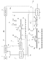
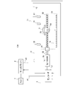
- FIG. 1 is a first diagram showing a schematic configuration of a servo system according to an embodiment of the invention
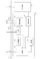
- FIG. 1 is a first diagram showing a schematic configuration of a motor
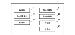
- FIG. 3 is a diagram showing a functional configuration of a servo driver
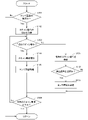
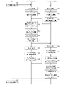
- FIG. 4 is a flowchart showing the flow of processing executed by each driver when executing sensor recognition processing
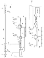
- 5 is a flow chart showing a flow of specific processing performed between a PLC and a servo driver when sensor recognition processing of the flow chart shown in FIG. 4 is performed
- FIG. 2 is a second diagram showing a schematic configuration of the servo system according to the embodiment of the invention
- 3 is a third diagram showing a schematic configuration of the servo system according to the embodiment of the invention
- FIG. FIG. 4 is a fourth diagram showing a schematic configuration of the servo system according to the embodiment of the present invention
- FIG. 1 is a block diagram schematically showing a configuration example of a servo system 100.
- a servo system 100 includes a PLC (Programmable Logic Controller) 1 and servo drivers 2 and 2a.
- Servo drivers 2 and 2a are arranged to drive and control servo motors 3 and 3a, respectively.
- the respective output shafts 32, 32a of the servo motors 3, 3a are connected to screw shafts 52, 52a by couplings 51, 51a.
- Precision stages 53, 53a are arranged on screw shafts 52, 52a, respectively, and are configured to be displaced by driving servo motors (hereinafter referred to as "motors") 3, 3a.
- motors driving servo motors
- Workpieces 8 and 8a are placed on precision stages 53 and 53a, respectively.
- two drive shafts, one driven by the motor 3 and the other driven by the motor 3a, are provided, but three or more drive shafts may be provided.
- a linear scale 54, an origin sensor 61, limit sensors 62 and 63, and a fully closed sensor 64 are arranged on the drive shaft driven by the motor 3, and a linear scale 54a and , an origin sensor 61a, limit sensors 62a and 63a, and a fully closed sensor 64a. These sensors detect parameters related to the displacement of the precision stages 53 and 53a, which are the detection targets.
- the origin sensors 61 and 61a detect the origin positions of the precision stages 53 and 53a, output an ON signal when each stage reaches its respective limit position, and output an OFF signal when it is at any other position.
- the limit sensors 62, 63, 62a, 63a detect the end positions of the movable ranges of the precision stages 53, 53a on the drive axes, and output ON signals when the respective stages reach their respective end positions, When it is in any other position, it outputs an OFF signal.
- the limit sensor 62 or the like is turned on, the precision stage 53 is stopped by stopping the motor 3 .
- a photoelectric sensor, a proximity sensor, a fiber sensor, or the like can be used as the origin sensor and the limit sensor.
- image sensors may be used as origin and limit sensors. In this case, the detection signal by each sensor becomes an image signal.
- the linear scales 54, 54a are installed along the axial direction of the screw shafts 52, 52a.
- the linear scales 54 and 54a are, for example, reflective photoelectric glass scales, and are provided with slits at equal pitches.
- the fully closed sensors 64, 64a are installed on the precision stages 53, 53a and move together with the precision stages 53, 53a.
- the fully closed sensor 64, 64a has a light-emitting portion and a light-receiving portion (both not shown). The light emitted from the light-emitting portion is reflected by the corresponding slits of the linear scales 54, 54a to generate interference fringes on the light-receiving portion.
- the intensity of the output signal from the light receiving section changes according to the movement of the precision stages 53 and 53a. Therefore, by monitoring the intensity change of the output signal from the light receiving section, the amount of movement of the precision stages 53, 53a can be obtained. That is, the fully closed sensors 64, 64a output detection signals for calculating the amount of movement of the precision stages 53, 53a, and the detection signals are used for full closed control in the servo drivers 2, 2a.
- the PLC 1 outputs command signals to the servo drivers 2 and 2a.
- the PLC 1 functions, for example, as a monitoring device for the servo drivers 2 and 2a by executing processing according to a program prepared in advance.
- the servo drivers 2 and 2a receive command signals from the PLC1. Further, the servo drivers 2, 2a receive feedback signals from the motors 3, 3a, respectively, and detect detection output from corresponding origin sensors 61, 61a, limit sensors 62, 63, 62a, 63a or fully closed sensors 64, 64a. receive a signal.
- the servo drivers 2 and 2a each form a servo system that performs feedback control using a position controller, a speed controller, a current controller, etc. Using these signals, the motor 3 is servo-controlled. and drive.
- the motor 3 includes a motor body 30 and an encoder 31, and the motor 3a includes a motor body 30a and an encoder 31a.
- the motors 3, 3a are, for example, AC servomotors. Motors 3 and 3a are supplied with drive currents from servo drivers 2 and 2a through power lines 40 and 40a, respectively.
- Encoders 31 and 31a detect the operation of motor bodies 30 and 30a, respectively.
- the encoders 31, 31a respectively output feedback signals indicating detected motions to the servo drivers 2, 2a via the encoder cables 41, 41a.
- the origin sensor 61, the limit sensors 62, 63 and the fully closed sensor 64 are assigned to the drive shaft associated with the motor 3, the origin sensor 61a, the limit sensors 62a, 63a and the fully closed sensor 64a are associated with the motor 3a is assigned to the drive shaft associated with it.
- the sensor cable from each sensor is not necessarily connected to the encoder of the motor of its assigned drive shaft, but to the encoder of the motor closer to that sensor. be.
- encoder 31 a is arranged closer than encoder 31 .
- cable 71 from origin sensor 61 and cable 73 from limit sensor 63 are connected to encoder 31a.
- Such a configuration is realized by arranging a plurality of encoders.
- the origin sensor 61a and the limit sensor 63a are assigned to the motor 3a, but the encoder 31 is located closer to the origin sensor 61a and the limit sensor 63a than the encoder 31a. Therefore, in this embodiment, the cable 71a from the origin sensor 61a and the cable 73a from the limit sensor 63a are connected to the encoder 31.
- FIG. 1 the origin sensor 61a and the limit sensor 63a are assigned to the motor 3a, but the encoder 31 is located closer to the origin sensor 61a and the limit sensor 63a than the encoder 31a. Therefore, in this embodiment, the cable 71a from the origin sensor 61a and the cable 73a from the limit sensor 63a are connected to the encoder 31.
- the remaining sensors can also be connected via cables to the nearest encoder among the encoders 31 and 31a.
- limit sensor 62 and fully closed sensor 64 are connected to encoder 31 by cables 72 and 74, respectively, and limit sensor 62a and fully closed sensor 64a are connected to cables 72a and 74a, respectively. is connected to the encoder 31a. That is, for these sensors, the closer encoder is coincident with the encoder that detects motion of the motor to which the sensor is assigned.
- FIG. 2 schematically shows the configuration of the encoder 31 as a representative, substantially the encoder 31a also has the same functional configuration.
- Encoder 31 includes signal generator 311 , input unit 312 , A/D (analog-digital) converter 313 , communication unit 314 , power supply unit 315 , and display unit 316 .
- the signal generator 311 detects the motion of the motor body 30 of the motor 3 driven by the servo driver 2 and generates a feedback signal indicating the detected motion.
- the feedback signal is output to communication section 314 .
- the feedback signal includes, for example, information about the rotational position (angle) of the rotating shaft of the motor body 30, information about the rotating speed of the rotating shaft, information about the rotating direction of the rotating shaft, and the like.
- a known incremental type or absolute type configuration can be applied to the configuration of the signal generator 311 .
- a detection signal from each sensor is input to the input unit 312 .
- the cable 72 of the limit sensor 62, the cable 74 of the fully closed sensor 64, the cable 71a of the origin sensor 61a, and the cable 73a of the limit sensor 63a are connected to the input section 312.
- Input unit 312 is, for example, a terminal block or a connector for connecting wiring.
- the input unit 312 functions as an input interface for receiving detection signals from each sensor via each cable.
- the input detection signal is output from the input section 312 to the A/D conversion section 313 .
- A/D conversion section 313 A/D converts the detection signal from input section 312 and outputs the converted digital signal to communication section 314 .
- the communication unit 314 is an interface for communicating with the servo driver 2.
- the communication unit 314 sends the feedback signal and the detection signal from each sensor to the servo driver 2 via the encoder cable 41 .
- the feedback signal and the detection signal from each sensor are sent to the servo driver 2a via the encoder cable 41a.
- serial communication is applied to the transmission of the feedback signal and detection signal from the communication section 314 .
- a known communication standard such as RS-232C (Recommended Standards 232), RS-422, or RS-485 can be adopted.
- the encoder 31 is supplied with electric power from the servo driver 2 via the encoder cable 41 .
- the power supply unit 315 is a functional unit that supplies part of the power obtained from the servo driver 2 via the encoder cable 41 to each sensor connected by the cable. Part of the power is passed from the communication unit 314 to the power supply unit 315 .
- each cable connected to the input unit 312 and each cable connected to the power supply unit 315 are shown separately in FIG. Transmission and reception of detection signals and power supply are performed. As an alternative method, cables connecting each sensor, the input unit 312, and the power supply unit 315 may be wired separately.
- the display unit 316 is an LED that lights up according to the input when the detection signal from each sensor is input to the input unit 312 . That is, the encoder 31 is provided with LEDs corresponding to the number of cables of each sensor connected, and when a detection signal is input, the LED corresponding to the sensor that sent the detection signal lights up. . Note that the display unit 316 may be a display such as a liquid crystal instead of an LED, and in that case, the sensor that receives the input of the detection signal may be displayed on the display.
- the respective encoders 31 and 31a are in a state where the servo drivers 2 and 2a can communicate with each other. It has an operation mode corresponding to its use. In this mode of operation, each encoder 31, 31a sends a detection signal from each sensor to the servo driver, but the detection signal has to reach the specific servo driver that needs it.
- a communication cable 42 connects the servo driver 2 and the servo driver 2a. Each of the servo drivers 2 and 2a transmits the detection signal from each sensor to the servo driver that needs it, or receives it by itself.
- the servo driver 2 receives, from the encoder 31, detection signals from the limit sensor 62, the fully closed sensor 64, the origin sensor 61a, and the limit sensor 63a. Detection signals from the limit sensor 62 and the fully closed sensor 64 are signals to be processed by the servo driver 2, whereas detection signals from the origin sensor 61a and the limit sensor 63a are to be processed by the servo driver 2a. is a signal. Therefore, the servo driver 2 transfers detection signals from the origin sensor 61a and the limit sensor 63a to the servo driver 2a.
- the servo driver 2a receives detection signals from the origin sensor 61, the limit sensor 63, the limit sensor 62a, and the fully closed sensor 64a from the encoder 31a. Detection signals from the limit sensor 62a and the fully closed sensor 64a are signals to be processed by the servo driver 2a, whereas detection signals from the origin sensor 61 and the limit sensor 63 are to be processed by the servo driver 2. is a signal. Therefore, the servo driver 2a transfers detection signals from the origin sensor 61 and the limit sensor 63 to the servo driver 2a.
- FIG. 3 shows a schematic configuration of the functional units of the servo driver 2.
- the servo driver 2 can be regarded as a computer having an arithmetic device, a storage device, etc., and the functional units shown in FIG. Since the servo driver 2a also has similar functional units, a detailed description of the servo driver 2a will be omitted.
- the servo driver 2 has a communication unit 21, a servo control unit 22, a storage unit 23, a first processing unit 24, a second processing unit 25, a determination unit 26, and a transmission unit 27, but has other functional units. I don't mind.
- the communication unit 21 is a function that controls communication with the outside via the communication cable 42.
- the communication unit 21 functions as an interface for communication with the PLC 1 and other servo drivers (such as the servo driver 2a).
- the communication section 21 also functions as an interface for communication with the encoder 31 via the encoder cable 41 .
- the servo control unit 22 is a functional unit for servo-controlling the motor 3 based on commands from the PLC 1. Specifically, the servo control unit 22 performs feedback control using a position controller, a speed controller, a current controller, and the like. , and a functional unit that uses detection signals from the sensors assigned to the servo driver 2 for the feedback control.
- the storage unit 33 is a functional unit that stores information related to the processing performed by the servo driver 2, such as information necessary for servo control of the motor 3 and information necessary for recognition processing of corresponding sensors by the servo driver. be.
- the storage unit 23 stores information (correspondence relation information) indicating the link relation between the servo driver and each sensor, which is determined by recognition processing of the corresponding sensor, which will be described later. Then, based on the stored correspondence information, the servo driver 2 assigns the destination of the detection signal sent from each sensor, and specifies the destination servo driver via the communication unit 21 as necessary. process to send out the detection signal from the sensor.
- the first processing unit 24 When the first processing unit 24 receives a detection signal from a specific sensor when the first predetermined operation of driving the output shaft 32 of the motor 3 and displacing the precision table 53 is performed, the first processing unit 24 activates the specific sensor. It is a functional unit that recognizes a corresponding sensor linked to the driver 2 .
- the particular sensor has not yet been recognized by the servo driver 2, but is arranged so that its detection signal is received by the servo driver 2, and is the sensor that should be finally assigned to the servo driver 2.
- the limit sensor 62 and the fully closed sensor 64 correspond.
- the first predetermined motion is a movement motion in the entire drivable range from when the precision stage 53 starts moving from one end to reaches the other end.
- the second processing unit 25 transmits information about a sensor different from the specific sensor from a servo driver other than the servo driver 2 (the servo driver 2a in this embodiment). It is a functional unit that recognizes a sensor different from the specific sensor as a corresponding sensor linked to the servo driver 2 according to the received information when it is received.
- a sensor different from the specific sensor is arranged so that its detection signal is received by the servo driver 2a although it has not yet been recognized by the servo driver 2, and should be finally assigned to the servo driver 2.
- These sensors are the origin sensor 61 and the limit sensor 63 in this embodiment. Information about the origin sensor 61 and the limit sensor 63 is transmitted from the servo driver 2a to the servo driver 2 by a transmitting section 27 of the servo driver 2a, which will be described later.
- the determination unit 26 determines the sensor type of the sensor recognized by the first processing unit 24 and the sensor recognized by the second processing unit 25 based on the position information of the precision stage 53 when each sensor is recognized. It is a functional part. Since the detection signals of the limit sensor 61 , the origin sensors 62 and 63 sensors, and the fully closed sensor 64 fluctuate according to the displacement of the precision stage 53 , the detection signals have a strong correlation with the position of the precision stage 53 . Using the correlation, the sensor type determination processing is performed by the determining unit 26 .
- the transmission unit 27 performs a second predetermined operation of driving only the output shaft of the motor 3a corresponding to a servo driver (servo driver 2a in this embodiment) different from the servo driver 2 to displace the precision stage 53a. If a detection signal is received from a specific sensor when the servo driver 2a , to the servo driver 2a. The particular sensor is not yet recognized by the servo driver 2a, but is positioned so that its detection signal is received by the servo driver 2, and is the sensor that should be finally assigned to the servo driver 2a. , in the case of this embodiment, the origin sensor 61a and the limit sensor 63a.
- the second predetermined motion is a movement motion in the entire drivable range from when the precision stage 53a starts moving from one end to reaches the other end.
- FIG. 4 is a flow chart schematically showing the flow of processing performed by each of the servo drivers 2 and 2a, and FIG. It is the flowchart which showed the flow of a process roughly.
- the processing shown in FIG. 4 is repeatedly executed at predetermined time intervals.
- S101 it is determined whether or not an instruction to perform sensor recognition processing has arrived from the PLC1. If an affirmative determination is made in S101, the process proceeds to S102, and if a negative determination is made, the process is terminated.
- S102 according to the sensor recognition processing instruction received from the PLC 1, the order of scanning operations in each servo driver is obtained.
- the scanning operation refers to a first predetermined operation and a second predetermined operation that are executed for processing by the first processing unit 24 and the second processing unit 25 described above.
- the scan operation is performed on each drive axis on which sensor recognition processing is performed in order to extract a sensor that outputs a detection signal in response to the drive operation when only the corresponding motor is driven. It is the action of the motor that moves the precision table from one end to the other, ie through the entire range of motion. More specifically, from a state in which the precision table 53 is in contact with a stopper (not shown) provided at one end of the movable range along the screw shaft 52, the stopper provided at the other end is (not shown), the motor 3 is driven at a low and constant speed until the precision table 53 contacts. During this drive, the torque of the motor 3 is controlled so that the impact when the precision table 53 comes into contact with the stopper is reduced as much as possible.
- the order of scan operations of the drive axes by the servo drivers 2 and 2a is first and second, respectively.
- S103 it is determined whether or not the scan operation order in the servo driver 2 has arrived. If an affirmative determination is made in S103, the process proceeds to S104, and if a negative determination is made, the process proceeds to S106.
- S104 the scan operation on the drive shaft by the servo driver 2, that is, the scan operation by the motor 3 is started.
- the scanning operation causes the limit sensor 62, the origin sensor 61, the limit sensor In the order of 63, detection signals are sent from each sensor to the servo drivers 2 and 2a via the connected encoders 31 and 31a.
- the detection signal from the fully closed sensor 64 is transmitted to the servo driver 2 throughout the scanning operation.
- the encoders 31 and 31a are provided with a display section 316, and when the detection signal from each sensor is input to each encoder, the diode of the display section 316 lights up at the input timing of the detection signal. Thereby, the user can visually recognize the input of the detection signal of the sensor.
- the detection signal from each sensor contains identification information for identifying the sensor that generated the signal, and each servo driver that receives the detection signal can grasp which sensor the detection signal is from. can. After the process of S104 is completed, the process proceeds to S105.
- sensor recognition processing is performed by the first processing unit 24 and the second processing unit 25 according to the scanning operation started in S104. Specifically, when the detection signal of the limit sensor 62 and the detection signal of the fully closed sensor 64 reach the servo driver 2 with the scanning operation, these sensors correspond to the servo driver 2 by the first processing unit 24. Recognize that it is a sensor. Further, when the detection signal of the origin sensor 61 and the detection signal of the limit sensor 62 reach the servo driver 2a along with the scanning operation, the transmission unit (functional unit corresponding to the transmission unit 27 in FIG.
- the servo driver 2a transmits information about these sensors to the servo driver 2, which is a servo driver other than itself, and receives the information via the communication unit 21 from the servo driver 2g.
- the information about the sensors includes identification information that identifies each sensor.
- the second processing unit 25 recognizes that these sensors also correspond to the servo driver 2 .
- the determination unit 26 determines the sensor type. Specifically, of the limit sensors 62 and 63, the origin sensor 61, and the fully closed sensor 64, the limit sensors 62 and 63 output detection signals when the precision table 53 is positioned at the outermost position of the movable range. Therefore, the sensor type can be determined as a "limit sensor” based on the position information (position information indicating the outermost position) of the precision table 53 when the detection signal is issued. Further, the type of sensor that outputs a detection signal in the middle of the movable range of the precision table 53 can be determined as the "origin sensor". Further, while the scanning operation is being performed, that is, a sensor that constantly outputs a detection signal regardless of the position of the precision table 53 can be determined as a "fully closed sensor". When the process of S105 is completed, the process proceeds to S109.
- this sensor should be linked to a servo driver different from the servo driver 2, if the determination in S107 is affirmative, the process proceeds to S108, and the transmission unit 27 transmits sensor information about the sensor.
- the destination of the sensor information is the servo driver corresponding to the drive axis that was performing the scanning operation when the detection signal was received.
- the destination servo driver can inquire of the PLC 1 or the target servo driver 2a via the communication cable 42 .
- the process of S108 ends, the process proceeds to S109, and when a negative determination is made in S107, the process proceeds to S109.
- the PLC 1 issues an instruction for sensor recognition processing to all the servo drivers 2 and 2a included in the servo system 100.
- FIG. According to this instruction, the processing shown in FIG. 4 is executed by each servo driver.
- the motor 3 is driven by the servo driver 2 in S21 to start the scanning operation (see the process of S104 in FIG. 4).
- the motor 3a is stopped (see the process of S31).
- the detection signals of the limit sensor 62 and the fully closed sensor 64 are received by the servo driver 2 via the encoder 31 in S22.
- detection signals from the origin sensor 61 and the limit sensor 63 are received by the servo driver 2a via the encoder 31a (see the process of S32).
- the servo driver 2a is in a state of waiting for the scanning operation on the drive axis by the servo driver 2 by the processing of S106 shown in FIG.
- the servo driver 2a that has received these detection signals transmits information about the sensor that generated these detection signals to the servo driver 2 by its own transmission unit (see the processing of S33). 2 receives information about the sensor.
- the origin sensor 61, the limit sensors 62 and 63, and the fully closed sensor 64 are recognized as sensors corresponding to the servo driver 2, and in S25, the sensor type of each sensor is determined (S105 in FIG. 4). processing).
- the sensor recognition result and the sensor type determination result are stored in the storage unit 23 of the servo driver 2 .
- the servo driver 2a for the drive axis on which the next scan operation is to be performed is notified that the scan operation on the drive axis by the servo driver 2 has been completed. Thereby, the servo driver 2a knows that it is the turn to perform the scanning operation on its own drive axis.
- the motor 3 of the servo driver 2 is stopped (see the process of S27), and the servo driver 2 waits for the scanning operation on the drive axis by the servo driver 2a by the process of S106 shown in FIG. is placed in a state where
- detection signals from the origin sensor 61a and the limit sensor 63a are received by the servo driver 2 via the encoder 31 (see the process of S28).
- the servo driver 2 which has received these detection signals, transmits information about the sensor that generated these detection signals to the servo driver 2a by means of its own transmission unit 27 (see the processing of S29). , the servo driver 2a receives information about the sensor.
- the origin sensor 61a, limit sensors 62a and 63a, and fully closed sensor 64a are recognized as sensors corresponding to the servo driver 2a, and in S38, the sensor type of each sensor is determined (S105 in FIG. processing).
- the sensor recognition result and the sensor type determination result are stored in the storage unit of the servo driver 2a.
- the PLC 1 is notified that the scan operation on all the drive axes has been completed by the completion of the scan operation on the drive axes by the servo driver 2a. Thereby, PLC1 is S12 and knows that the sensor recognition process was completed.
- the servo drivers 2 and 2a can recognize the corresponding sensors.
- each sensor does not necessarily have to be connected to the encoder of the motor driven by the corresponding servo driver. is realized. Therefore, it becomes easy to construct the servo system 100 for servo control of each drive axis while reducing the load of the wiring work of the sensor.
- FIG. 6 is a block diagram schematically showing a configuration example of the servo system 100 of this embodiment.
- the encoder 31 a also has the same configuration as the encoder 31 .
- the detection signals from the sensors are input to the encoders 31, 31a of the motors 3, 3a and then delivered to the servo drivers 2, 2a via the encoder cables 41, 41a.
- the detection signal from each is sent to the corresponding servo driver via wireless communication.
- the detection signals from the sensors are assigned to the servo driver. 2, 2a must be properly reached, and for that purpose, the servo drivers 2, 2a are required to properly recognize the corresponding sensor.
- the configuration of the servo system 100 of this embodiment will be described.
- the origin sensor 61 and the origin sensors 62 and 63 have a wireless communication function.
- the fully closed sensor 64 is connected to the encoder 31 via the cable 74, as in the first embodiment. Therefore, only the detection signal from the fully closed sensor 64 is input to the input section 312 of the encoder 31 , and power is supplied to the fully closed sensor 64 from the power supply section 315 .
- the communication unit 21 of the servo driver 2 has a communication function for enabling wireless communication with the origin sensor 61 and the origin sensors 62 and 63 .
- Each sensor having a wireless communication function has an internal battery and does not receive power supply from the outside. Alternatively, each sensor may be configured to receive power supply from the outside (including the encoder 31, for example) through a power supply line (not shown).
- the origin sensor 61a and the origin sensors 62a, 63a have a wireless communication function.
- the fully closed sensor 64a is connected to the encoder 31a via a cable 74a, as in the first embodiment. Therefore, only the detection signal from the fully closed sensor 64a is input to the input section of the encoder 31a, and power is supplied to the fully closed sensor 64a from the power supply section.
- the communication section of the servo driver 2a has a communication function for enabling wireless communication with the origin sensor 61a and the origin sensors 62a and 63a.
- each sensor having a wireless function has not undergone recognition processing by the servo drivers 2 and 2a.
- a detection signal from each sensor having a wireless function can be received by each of the servo drivers 2 and 2a via wireless. It is unclear whether it is assigned or not, and in this state, servo control of the motor by each servo driver cannot be realized. Therefore, by applying the sensor recognition processing disclosed in the first embodiment to the servo system 100 in which the sensor recognition processing by such a servo driver has not been completed, the link between the servo driver and each sensor can be obtained. Attachment can be suitably realized. In the case of this embodiment, even before the completion of the sensor recognition process, the detection signal from the sensor having the wireless function is received by any of the servo drivers. It is not necessary to provide a functional unit corresponding to the transmitting unit 27 shown in .
- FIG. 7 is a block diagram schematically showing a configuration example of the servo system 100, similar to FIG.
- the detection signal from each sensor is once received by the repeater 150 via radio, and further delivered from the repeater 150 to each servo driver 2, 2a. That is, the communication section 21 of each servo driver 2, 2a does not have a wireless function.
- the detection signals from each sensor are assigned.
- the servo drivers 2, 2a are required to properly recognize the corresponding sensors. Therefore, as in the second embodiment, by applying the sensor recognition processing disclosed in the first embodiment, it is possible to suitably realize the linkage between the servo driver and each sensor.
- FIG. 8 is a block diagram schematically showing a configuration example of the servo system 100 of this embodiment.
- the servo system 100 of this embodiment includes only one drive shaft. Therefore, unlike the first embodiment, origin sensor 61 and limit sensor 63 are connected to encoder 31 by cables 71 and 73, respectively. With this configuration, detection signals from the origin sensor 61 and the limit sensor 63 are transmitted to the encoder 31 , and power is supplied from the encoder 31 to the origin sensor 61 and the limit sensor 63 .
- the sensor recognition processing shown in FIG. 4 can be substantially applied to such a system configuration as well.
- the servo system 100 has only one drive axis, there is only one drive axis for the scanning operation, that is, only the scanning operation by the motor 3 is performed.
- the detection signals of the origin sensor 61 and the limit sensors 62 and 63 obtained by the scanning operation are temporarily collected in the servo driver 2, and the sensor recognition processing of S105 is performed.
- the processing of S106-S108 shown in FIG. 4 is not performed. As a result, even in the servo system 100 having a single drive axis, sensor recognition processing can be suitably realized.
- a servo driver (2) configured to drive a first motor (3) and communicatively connected to another servo driver (2a), comprising: A detection signal by a first sensor (62, 64) for detecting a parameter related to displacement of a first driven object (53) driven via an output shaft (32) of the first motor (3) is detected by the servo.
- a detection signal by another sensor (61, 63) arranged to be received by a driver (2) and detecting another parameter related to the displacement of said first driven object (53) is detected by said another arranged to be received by a servo driver (2a),
- the servo driver (2) When the first predetermined operation of displacing the first driven object (53) by driving only the output shaft (32) of the first motor (3) is performed while the sensor recognition processing is not completed.
- a detection signal is received from the first sensor (62, 64), a first processing unit ( 24) and The servo driver (2) associates the other sensors (61, 63) with the servo driver (2) when the first predetermined operation is performed in a state in which sensor recognition processing is not completed.
- the another sensor When predetermined information about the other sensor (61, 63) for enabling recognition as another corresponding sensor is received from the another servo driver (2a), the another sensor according to the predetermined information a second processing unit (25) that recognizes (61, 63) as another corresponding sensor; a servo driver.
- a servo driver (2) configured to drive a first motor (3), comprising:
- the first motor (3) is a motor body (30) including an output shaft (32); an encoder (31) having a signal generator that detects the motion of the motor body (30) driven by the servo driver (2) and generates a feedback signal indicating the detected motion; has Sensor cables (72, 74) to the encoder (31), the signals detected by the first sensors (62, 64) are sent to the encoder (31), and the first sensors (62, 64) are , powered by the encoder (31) through the sensor cables (72, 74),
- the servo driver (2) is transmitted through the sensor cables (72, 74) together with the feedback signal generated by the signal generator through a communication cable (41) connected to the encoder (31). Acquiring the detection signal of the first sensor (62, 64), servo driver.
- a servo system (100) comprising:
- the first servo driver (2) includes a first sensor (62 , 64) configured to receive detection signals from
- the second servo driver (2a) is configured to receive detection signals from another sensor (61, 63) that detects another parameter related to the displacement of the first driven object (53),
- the second servo driver (2a) drives only the output shaft (32) of the first motor (3) to displace the first driven object (32) while sensor recognition processing is not completed.
- the first servo driver (2) When the second servo driver (2a) receives a detection signal from the another sensor (61, 63) when the first predetermined operation is performed, the first servo driver (2) Information about the other sensor (61, 63) for enabling the sensor (61, 63) to be recognized as another corresponding sensor linked to the first servo driver (2) is provided to the first servo driver (2). configured to transmit to a servo driver (2); said first servo driver (2) is configured to recognize said another sensor (61, 63) as said another corresponding sensor according to information about said another sensor (61, 63); servo system.
- a method of sensor recognition processing by a servo system (100) comprising:
- the first servo driver (2) includes a first sensor (62 , 64) configured to receive detection signals from
- the second servo driver (2a) is configured to receive detection signals from another sensor (61, 63) that detects another parameter related to the displacement of the first driven object (53),
- the method includes: When the first predetermined operation of displacing the first driven object (53) by driving only the output shaft (32) of the first motor (3) is performed while the sensor recognition processing is not completed.
- the first servo driver (2) detects the another sensor (61, 63) as the first Information about the other sensors (61, 63) for enabling recognition as another corresponding sensor linked to the first servo driver (2) is transferred from the second servo driver (2a) to the first servo driver (2a). sending to a servo driver (2); a step of the first servo driver (2) recognizing the another sensor (61, 63) as the another corresponding sensor according to information about the another sensor (61, 63);
- a method of sensor recognition processing comprising:
Landscapes
- Engineering & Computer Science (AREA)
- Physics & Mathematics (AREA)
- General Physics & Mathematics (AREA)
- Automation & Control Theory (AREA)
- Human Computer Interaction (AREA)
- Manufacturing & Machinery (AREA)
- Computer Hardware Design (AREA)
- Microelectronics & Electronic Packaging (AREA)
- Power Engineering (AREA)
- Control Of Position Or Direction (AREA)
- Programmable Controllers (AREA)
- Control Of Multiple Motors (AREA)
Abstract
Description
図1は、サーボシステム100の構成例を概略的に示すブロック図である。図1を参照して、サーボシステム100は、PLC(Programmable Logic Controller)1と、サーボドライバ2、2aとを含む。サーボドライバ2、2aはそれぞれサーボモータ3、3aを駆動制御するように配置される。サーボモータ3、3aのそれぞれの出力軸32、32aは、カップリング51、51aによって、ねじ軸52、52aと繋がれている。ねじ軸52、52aのそれぞれには精密ステージ53、53aが配置され、サーボモータ(以下、「モータ」という)3、3aの駆動により精密ステージ53、53aが変位するように構成されている。精密ステージ53、53aには、それぞれ、ワーク8、8aが載せられている。このように図に示すサーボシステム100においては、モータ3による駆動軸と、モータ3aによる駆動軸の2つの駆動軸が設けられているが、駆動軸は3本以上設けられていてもよい。
センサ認識処理では、各センサを、対応するサーボドライバで駆動されるモータのエンコーダに必ずしも接続する必要はなく、近傍に位置するモータのエンコーダに接続した場合でも、好適にサーボドライバと各センサとの紐付け処理が実現される。したがって、センサの配線作業の負荷を軽減させながら、各駆動軸のサーボ制御のためのサーボシステム100の構築が容易となる。
本開示の第2の実施形態について、図6に基づいて説明する。図6は、本実施形態のサーボシステム100の構成例を概略的に示すブロック図である。エンコーダ31aもエンコーダ31と同等の構成を有している。
本開示の第3の実施形態について、図8に基づいて説明する。図8は、本実施形態のサーボシステム100の構成例を概略的に示すブロック図である。本実施形態のサーボシステム100においては、駆動軸は1つしか含まれていない。したがって、第1の実施形態と異なり、原点センサ61と限界センサ63は、それぞれケーブル71、73によってエンコーダ31に接続される。このような構成により、原点センサ61と限界センサ63の検出信号はエンコーダ31に送信され、また、エンコーダ31から原点センサ61と限界センサ63に電力が供給される。
第1モータ(3)を駆動するように構成され、且つ、別のサーボドライバ(2a)とも通信可能に接続されるサーボドライバ(2)であって、
前記第1モータ(3)の出力軸(32)を介して駆動される第1駆動対象(53)の変位に関連するパラメータを検出する第1センサ(62、64)による検出信号が、前記サーボドライバ(2)によって受信されるように配置され、且つ、前記第1駆動対象(53)の変位に関連する別のパラメータを検出する別のセンサ(61、63)による検出信号が、前記別のサーボドライバ(2a)によって受信されるように配置され、
前記サーボドライバ(2)は、
センサ認識処理が完了していない状態で、前記第1モータ(3)の出力軸(32)のみを駆動させて前記第1駆動対象(53)を変位させる第1所定動作が行われたときに前記第1センサ(62、64)から検出信号を受信した場合、該第1センサ(62、64)を、前記サーボドライバ(2)に紐付けられる第1対応センサと認識する第1処理部(24)と、
センサ認識処理が完了していない状態で前記第1所定動作が行われたときに、前記サーボドライバ(2)が、前記別のセンサ(61、63)を該サーボドライバ(2)に紐付けられる別の対応センサと認識することを可能にするための、該別のセンサ(61、63)に関する所定情報を、前記別のサーボドライバ(2a)から受信した場合、該所定情報に従って該別のセンサ(61、63)を該別の対応センサと認識する第2処理部(25)と、
を備える、サーボドライバ。
第1モータ(3)を駆動するように構成されるサーボドライバ(2)であって、
前記第1モータ(3)は、
出力軸(32)を含むモータ本体(30)と、
前記サーボドライバ(2)により駆動される前記モータ本体(30)の動作を検出して、検出された動作を示すフィードバック信号を生成する信号生成部を有するエンコーダ(31)と、
を有し、
前記第1モータ(3)の出力軸(32)を介して駆動される第1駆動対象(53)の変位に関連するパラメータを検出する第1センサ(62、64)が、センサケーブル(72、74)を介して前記エンコーダ(31)に接続されることで、該第1センサ(62、64)による検出信号が該エンコーダ(31)に送られるとともに、該第1センサ(62、64)は、該センサケーブル(72、74)を介して該エンコーダ(31)から電力が供給され、
前記サーボドライバ(2)は、前記エンコーダ(31)と繋がれる通信ケーブル(41)を介して、前記信号生成部で生成された前記フィードバック信号とともに前記センサケーブル(72、74)を介して送信された前記第1センサ(62、64)の検出信号を取得する、
サーボドライバ。
第1モータ(3)を駆動するように構成された第1サーボドライバ(2)と、
前記第1サーボドライバ(2)と通信可能に接続され、第2モータ(3a)を駆動するように構成された第2サーボドライバ(2a)と、
を含むサーボシステム(100)であって、
前記第1サーボドライバ(2)は、前記第1モータ(3)の出力軸(32)を介して駆動される第1駆動対象(53)の変位に関連するパラメータを検出する第1センサ(62、64)による検出信号を受信するように構成され、
前記第2サーボドライバ(2a)は、前記第1駆動対象(53)の変位に関連する別のパラメータを検出する別のセンサ(61、63)による検出信号を受信するように構成され、
前記第2サーボドライバ(2a)は、センサ認識処理が完了していない状態で、前記第1モータ(3)の出力軸(32)のみを駆動させて前記第1駆動対象(32)を変位させる第1所定動作が行われたときに、前記第2サーボドライバ(2a)が前記別のセンサ(61、63)から検出信号を受信した場合、該第1サーボドライバ(2)が、該別のセンサ(61、63)を、該第1サーボドライバ(2)に紐付けられた別の対応センサと認識することを可能にするための該別のセンサ(61、63)に関する情報を該第1サーボドライバ(2)に送信するように構成され、
前記第1サーボドライバ(2)は、前記別のセンサ(61、63)に関する情報に従って、前記別のセンサ(61、63)を前記別の対応センサと認識するように構成される、
サーボシステム。
第1モータ(3)を駆動するように構成された第1サーボドライバ(2)と、
前記第1サーボドライバ(2)と通信可能に接続され、第2モータ(3a)を駆動するように構成された第2サーボドライバ(2a)と、
を含むサーボシステム(100)による、センサ認識処理の方法であって、
前記第1サーボドライバ(2)は、前記第1モータ(3)の出力軸(32)を介して駆動される第1駆動対象(53)の変位に関連するパラメータを検出する第1センサ(62、64)による検出信号を受信するように構成され、
前記第2サーボドライバ(2a)は、前記第1駆動対象(53)の変位に関連する別のパラメータを検出する別のセンサ(61、63)による検出信号を受信するように構成され、
前記方法は、
センサ認識処理が完了していない状態で、前記第1モータ(3)の出力軸(32)のみを駆動させて前記第1駆動対象(53)を変位させる第1所定動作が行われたときに、前記第2サーボドライバ(2a)が前記別のセンサ(61、63)から検出信号を受信した場合、該第1サーボドライバ(2)が、該別のセンサ(61、63)を、該第1サーボドライバ(2)に紐付けられた別の対応センサと認識することを可能にするための該別のセンサ(61、63)に関する情報を、該第2サーボドライバ(2a)から該第1サーボドライバ(2)に送信するステップと、
前記第1サーボドライバ(2)が、前記別のセンサ(61、63)に関する情報に従って、前記別のセンサ(61、63)を前記別の対応センサと認識するステップと、
を含む、センサ認識処理の方法。
2、2a サーボドライバ
3、3a モータ
24 第1処理部
25 第2処理部
26 判定部
27 送信部
30、30a モータ本体
31、31a エンコーダ
32、32a 出力軸
53、53a 精密テーブル
54、54a リニアスケール
61、61a 原点センサ
62、62a、63、63a 限界センサ
64、64a フルクローズドセンサ
100 サーボシステム
150 中継装置
311 信号生成部
312 入力部
314 通信部
315 電源供給部
316 表示部
Claims (15)
- 第1モータを駆動するように構成され、且つ、別のサーボドライバとも通信可能に接続されるサーボドライバであって、
前記第1モータの出力軸を介して駆動される第1駆動対象の変位に関連するパラメータを検出する第1センサによる検出信号が、前記サーボドライバによって受信されるように配置され、且つ、前記第1駆動対象の変位に関連する別のパラメータを検出する別のセンサによる検出信号が、前記別のサーボドライバによって受信されるように配置され、
前記サーボドライバは、
センサ認識処理が完了していない状態で、前記第1モータの出力軸のみを駆動させて前記第1駆動対象を変位させる第1所定動作が行われたときに前記第1センサから検出信号を受信した場合、該第1センサを、前記サーボドライバに紐付けられる第1対応センサと認識する第1処理部と、
センサ認識処理が完了していない状態で前記第1所定動作が行われたときに、前記サーボドライバが、前記別のセンサを該サーボドライバに紐付けられる別の対応センサと認識することを可能にするための、該別のセンサに関する所定情報を、前記別のサーボドライバから受信した場合、該所定情報に従って該別のセンサを該別の対応センサと認識する第2処理部と、
を備える、サーボドライバ。 - 前記サーボドライバと通信可能に接続された第2サーボドライバによって第2モータの出力軸を介して駆動される第2駆動対象の変位に関連するパラメータを検出する第2センサによる検出信号が、前記サーボドライバによって受信されるように配置され、
前記サーボドライバは、更に、
前記センサ認識処理が完了していない状態で、前記第2モータの出力軸のみを駆動させて前記第2駆動対象を変位させる第2所定動作が行われたときに前記第2センサから検出信号を受信した場合、前記第2サーボドライバが、該第2センサを、該第2サーボドライバに紐付けられた第2対応センサと認識することを可能にするための該第2センサに関する情報を、該第2サーボドライバに送信する送信部を備える、
請求項1に記載のサーボドライバ。 - 前記別のサーボドライバは、前記第2サーボドライバである、
請求項2に記載のサーボドライバ。 - 前記第1モータは、
前記出力軸を含むモータ本体と、
前記サーボドライバにより駆動される前記モータ本体の動作を検出して、検出された動作を示すフィードバック信号を生成する信号生成部を有するエンコーダと、
を有し、
前記第1センサは、センサケーブルを介して前記エンコーダに接続され、
前記サーボドライバは、前記エンコーダと繋がれる通信ケーブルを介して、前記信号生成部で生成された前記フィードバック信号とともに前記センサケーブルを介して送信された前記第1センサの検出信号を取得する、
請求項1から請求項3の何れか1項に記載のサーボドライバ。 - 前記第1センサは、前記センサケーブルを介して前記エンコーダから電力が供給される、
請求項4に記載のサーボドライバ。 - 前記エンコーダは、前記第1センサから前記センサケーブルを介して検出信号が入力されたときに、その入力があったことを表す表示部を有する、
請求項4又は請求項5に記載のサーボドライバ。 - 前記第1センサは、無線を介して前記サーボドライバに通信可能に接続され、又は、無線を介して該第1センサと通信可能な所定装置を経由して該サーボドライバに通信可能に接続され、
前記サーボドライバは、無線を介して前記第1センサの検出信号を取得し、又は、前記所定装置を経由して該第1センサの検出信号を取得する、
請求項1に記載のサーボドライバ。 - 前記第1所定動作は、前記第1駆動対象が、一方の端部から移動開始し他方の端部に到達するまでの、該第1駆動対象の駆動可能な全範囲における移動動作である、
請求項1から請求項7の何れか1項に記載のサーボドライバ。 - 前記第1処理部により認識された前記第1センサ、及び前記第2処理部により認識された前記別のセンサのセンサ種類を、各センサが認識されたときの、前記第1駆動対象の駆動範囲における位置情報に基づいて判定する判定部を、更に備える、
請求項1から請求項8の何れか1項に記載のサーボドライバ。 - 第1モータを駆動するように構成されるサーボドライバであって、
前記第1モータは、
出力軸を含むモータ本体と、
前記サーボドライバにより駆動される前記モータ本体の動作を検出して、検出された動作を示すフィードバック信号を生成する信号生成部を有するエンコーダと、
を有し、
前記第1モータの出力軸を介して駆動される第1駆動対象の変位に関連するパラメータを検出する第1センサが、センサケーブルを介して前記エンコーダに接続されることで、該第1センサによる検出信号が該エンコーダに送られるとともに、該第1センサは、該センサケーブルを介して該エンコーダから電力が供給され、
前記サーボドライバは、前記エンコーダと繋がれる通信ケーブルを介して、前記信号生成部で生成された前記フィードバック信号とともに前記センサケーブルを介して送信された前記第1センサの検出信号を取得する、
サーボドライバ。 - 第1モータを駆動するように構成された第1サーボドライバと、
前記第1サーボドライバと通信可能に接続され、第2モータを駆動するように構成された第2サーボドライバと、
を含むサーボシステムであって、
前記第1サーボドライバは、前記第1モータの出力軸を介して駆動される第1駆動対象の変位に関連するパラメータを検出する第1センサによる検出信号を受信するように構成され、
前記第2サーボドライバは、前記第1駆動対象の変位に関連する別のパラメータを検出する別のセンサによる検出信号を受信するように構成され、
前記第2サーボドライバは、センサ認識処理が完了していない状態で、前記第1モータの出力軸のみを駆動させて前記第1駆動対象を変位させる第1所定動作が行われたときに、前記第2サーボドライバが前記別のセンサから検出信号を受信した場合、該第1サーボドライバが、該別のセンサを、該第1サーボドライバに紐付けられた別の対応センサと認識することを可能にするための該別のセンサに関する情報を該第1サーボドライバに送信するように構成され、
前記第1サーボドライバは、前記別のセンサに関する情報に従って、前記別のセンサを前記別の対応センサと認識するように構成される、
サーボシステム。 - 前記第1サーボドライバは、センサ認識処理が完了していない状態で前記第1所定動作が行われたときに、前記第1サーボドライバが前記第1センサから検出信号を受信した場合、該第1センサを、該第1サーボドライバに紐付けられる第1対応センサと認識するように、更に構成される、
請求項11に記載のサーボシステム。 - 前記第1サーボドライバは、更に、前記第2モータの出力軸を介して駆動される第2駆動対象の変位に関連するパラメータを検出する第2センサによる検出信号を受信するように構成され、
前記第1サーボドライバは、センサ認識処理が完了していない状態で、前記第2モータの出力軸のみを駆動させて前記第2駆動対象を変位させる第2所定動作が行われたときに、前記第1サーボドライバが前記第2センサから検出信号を受信した場合、該第2サーボドライバが、該第2センサを、該第2サーボドライバに紐付けられた第2対応センサと認識することを可能にするための該第2センサに関する情報を該第2サーボドライバに送信するように、更に構成される、
請求項11又は請求項12に記載のサーボシステム。 - 前記第1モータは、
前記出力軸を含むモータ本体と、
前記サーボドライバにより駆動される前記モータ本体の動作を検出して、検出された動作を示すフィードバック信号を生成する信号生成部を有するエンコーダと、
を有し、
前記第1センサは、センサケーブルを介して前記エンコーダに接続され、
前記サーボドライバは、前記エンコーダと繋がれる通信ケーブルを介して、前記信号生成部で生成された前記フィードバック信号とともに前記センサケーブルを介して送信された前記第1センサの検出信号を取得する、
請求項11から請求項13の何れか1項に記載のサーボシステム。 - 第1モータを駆動するように構成された第1サーボドライバと、
前記第1サーボドライバと通信可能に接続され、第2モータを駆動するように構成された第2サーボドライバと、
を含むサーボシステムによる、センサ認識処理の方法であって、
前記第1サーボドライバは、前記第1モータの出力軸を介して駆動される第1駆動対象の変位に関連するパラメータを検出する第1センサによる検出信号を受信するように構成され、
前記第2サーボドライバは、前記第1駆動対象の変位に関連する別のパラメータを検出する別のセンサによる検出信号を受信するように構成され、
前記方法は、
センサ認識処理が完了していない状態で、前記第1モータの出力軸のみを駆動させて前記第1駆動対象を変位させる第1所定動作が行われたときに、前記第2サーボドライバが前記別のセンサから検出信号を受信した場合、該第1サーボドライバが、該別のセンサを、該第1サーボドライバに紐付けられた別の対応センサと認識することを可能にするための該別のセンサに関する情報を、該第2サーボドライバから該第1サーボドライバに送信するステップと、
前記第1サーボドライバが、前記別のセンサに関する情報に従って、前記別のセンサを前記別の対応センサと認識するステップと、
を含む、センサ認識処理の方法。
Priority Applications (3)
| Application Number | Priority Date | Filing Date | Title |
|---|---|---|---|
| CN202180093670.0A CN116868135B (zh) | 2021-03-15 | 2021-12-20 | 伺服驱动器、伺服系统和传感器识别处理的方法 |
| DE112021007289.7T DE112021007289T5 (de) | 2021-03-15 | 2021-12-20 | Servotreiber, servosystem und sensorerkennungs-verarbeitungsverfahren |
| US18/548,233 US20240231314A9 (en) | 2021-03-15 | 2021-12-20 | Servo driver, servo system, and sensor recognition processing method |
Applications Claiming Priority (2)
| Application Number | Priority Date | Filing Date | Title |
|---|---|---|---|
| JP2021041194A JP7608894B2 (ja) | 2021-03-15 | 2021-03-15 | サーボドライバ、サーボシステム、及びセンサ認識処理の方法 |
| JP2021-041194 | 2021-03-15 |
Publications (1)
| Publication Number | Publication Date |
|---|---|
| WO2022196008A1 true WO2022196008A1 (ja) | 2022-09-22 |
Family
ID=83320301
Family Applications (1)
| Application Number | Title | Priority Date | Filing Date |
|---|---|---|---|
| PCT/JP2021/047111 Ceased WO2022196008A1 (ja) | 2021-03-15 | 2021-12-20 | サーボドライバ、サーボシステム、及びセンサ認識処理の方法 |
Country Status (5)
| Country | Link |
|---|---|
| US (1) | US20240231314A9 (ja) |
| JP (1) | JP7608894B2 (ja) |
| CN (1) | CN116868135B (ja) |
| DE (1) | DE112021007289T5 (ja) |
| WO (1) | WO2022196008A1 (ja) |
Citations (3)
| Publication number | Priority date | Publication date | Assignee | Title |
|---|---|---|---|---|
| US5511933A (en) * | 1993-01-08 | 1996-04-30 | Trantek, Incorporated | Shuttle transfer with linear Transducer feedback |
| JP2015095221A (ja) * | 2013-11-14 | 2015-05-18 | オムロン株式会社 | エンコーダおよびサーボシステム |
| JP6741924B1 (ja) * | 2019-12-23 | 2020-08-19 | 株式会社安川電機 | 分散モータ制御システム、モータ制御装置、及び分散モータ制御方法 |
Family Cites Families (18)
| Publication number | Priority date | Publication date | Assignee | Title |
|---|---|---|---|---|
| JP3278462B2 (ja) * | 1992-08-26 | 2002-04-30 | 株式会社東芝 | 自動化装置の初期位置設定装置 |
| JP2001265433A (ja) * | 2000-03-17 | 2001-09-28 | Advanced Technology Inst Of Commuter Helicopter Ltd | サーボ制御装置の故障検出方法 |
| JP3674569B2 (ja) * | 2001-10-04 | 2005-07-20 | オムロン株式会社 | センサ管理装置、センサ管理装置の制御プログラム、このプログラムを記録したコンピュータ読み取り可能な記録媒体、センサ管理装置の制御方法 |
| JP2003288103A (ja) * | 2002-03-27 | 2003-10-10 | Sony Corp | 情報処理装置及びその方法 |
| JP2008028756A (ja) * | 2006-07-21 | 2008-02-07 | Hitachi Ltd | 遠隔監視システム |
| KR20090020363A (ko) * | 2007-08-23 | 2009-02-26 | 세크론 주식회사 | 서보 모터 시스템 및 이를 이용하는 원점 복귀 방법 |
| JP5096843B2 (ja) * | 2007-08-30 | 2012-12-12 | 東洋機械金属株式会社 | 射出成形機 |
| JP2010082784A (ja) * | 2008-10-02 | 2010-04-15 | Olympus Corp | パラレルリンクステージの制御方法およびパラレルリンクステージ |
| CN201444183U (zh) * | 2009-05-12 | 2010-04-28 | 潍坊金诺科技有限公司 | 交流伺服电机的编码器接线检测装置 |
| CN103105826A (zh) * | 2011-11-11 | 2013-05-15 | 中国科学院沈阳科学仪器研制中心有限公司 | 一种真空设备运动定位控制系统及控制方法 |
| CN204823435U (zh) * | 2015-07-17 | 2015-12-02 | 四川腾邦摩托车配件有限公司 | 六轴全自动细线绕线机的控制电路 |
| JP6219424B2 (ja) * | 2016-03-02 | 2017-10-25 | 平田機工株式会社 | 制御方法、作業システムおよび製造方法 |
| JP6443365B2 (ja) * | 2016-03-10 | 2018-12-26 | オムロン株式会社 | モータ制御装置、制御方法、情報処理プログラム、および記録媒体 |
| JP6708517B2 (ja) * | 2016-08-09 | 2020-06-10 | 株式会社日立産機システム | サーボシステム |
| CN110495091B (zh) * | 2017-03-30 | 2023-01-20 | 株式会社安川电机 | 马达控制系统、控制方法以及马达控制装置 |
| WO2019155700A1 (ja) * | 2018-02-06 | 2019-08-15 | 三菱電機株式会社 | サーボシステム、センサハブ及び産業用装置の診断方法 |
| DE112019007298T5 (de) * | 2019-05-08 | 2022-01-27 | Yamaha Hatsudoki Kabushiki Kaisha | Linearfördersystem, linearmodul, steuerverfahren für linearmodul |
| CN110488742B (zh) * | 2019-08-28 | 2020-12-22 | 上海恒润文化科技有限公司 | 运动平台伺服的监测方法及系统 |
-
2021
- 2021-03-15 JP JP2021041194A patent/JP7608894B2/ja active Active
- 2021-12-20 DE DE112021007289.7T patent/DE112021007289T5/de active Pending
- 2021-12-20 US US18/548,233 patent/US20240231314A9/en active Pending
- 2021-12-20 WO PCT/JP2021/047111 patent/WO2022196008A1/ja not_active Ceased
- 2021-12-20 CN CN202180093670.0A patent/CN116868135B/zh active Active
Patent Citations (3)
| Publication number | Priority date | Publication date | Assignee | Title |
|---|---|---|---|---|
| US5511933A (en) * | 1993-01-08 | 1996-04-30 | Trantek, Incorporated | Shuttle transfer with linear Transducer feedback |
| JP2015095221A (ja) * | 2013-11-14 | 2015-05-18 | オムロン株式会社 | エンコーダおよびサーボシステム |
| JP6741924B1 (ja) * | 2019-12-23 | 2020-08-19 | 株式会社安川電機 | 分散モータ制御システム、モータ制御装置、及び分散モータ制御方法 |
Also Published As
| Publication number | Publication date |
|---|---|
| JP7608894B2 (ja) | 2025-01-07 |
| US20240134345A1 (en) | 2024-04-25 |
| US20240231314A9 (en) | 2024-07-11 |
| JP2022141061A (ja) | 2022-09-29 |
| DE112021007289T5 (de) | 2024-01-25 |
| CN116868135A (zh) | 2023-10-10 |
| CN116868135B (zh) | 2026-05-12 |
Similar Documents
| Publication | Publication Date | Title |
|---|---|---|
| KR102039077B1 (ko) | 원격조작 로봇시스템 및 그 운전방법 | |
| JP6349687B2 (ja) | エンコーダおよびサーボシステム | |
| US8339091B2 (en) | Communication apparatus for robots | |
| CN110267770B (zh) | 机器人系统及其控制方法 | |
| KR20140062848A (ko) | 이동식 용접로봇의 제어시스템 | |
| JP7608894B2 (ja) | サーボドライバ、サーボシステム、及びセンサ認識処理の方法 | |
| EP2335885A1 (en) | Computer vision device to automatically synchronize the speed and position of manipulator with the moving assembly line in the automotive industry | |
| JP7581989B2 (ja) | 中継器及びサーボシステム | |
| KR102420896B1 (ko) | 용접 로봇 제어시스템 및 그의 로봇 인식방법 | |
| JP2019040264A (ja) | 工作機械とロボットの連携システム | |
| RU203739U1 (ru) | Плата управления сервоприводом | |
| CN110561328B (zh) | 一种卫星姿态调整架车的控制系统 | |
| JP7677065B2 (ja) | モータ装置 | |
| CN109448352A (zh) | 一种基于无线通讯的伺服电机控制装置及方法 | |
| TW202425493A (zh) | 感應智動模組 | |
| CN117311270A (zh) | 一种用于更换机床附件头的控制系统及控制方法 | |
| JP2001297389A (ja) | センサ装置及びセンサ信号出力方法並びにモータ装置 |
Legal Events
| Date | Code | Title | Description |
|---|---|---|---|
| 121 | Ep: the epo has been informed by wipo that ep was designated in this application |
Ref document number: 21931750 Country of ref document: EP Kind code of ref document: A1 |
|
| WWE | Wipo information: entry into national phase |
Ref document number: 202180093670.0 Country of ref document: CN |
|
| WWE | Wipo information: entry into national phase |
Ref document number: 18548233 Country of ref document: US |
|
| WWE | Wipo information: entry into national phase |
Ref document number: 112021007289 Country of ref document: DE |
|
| 122 | Ep: pct application non-entry in european phase |
Ref document number: 21931750 Country of ref document: EP Kind code of ref document: A1 |