WO2022191041A1 - レンズ駆動装置及びカメラモジュール - Google Patents
レンズ駆動装置及びカメラモジュール Download PDFInfo
- Publication number
- WO2022191041A1 WO2022191041A1 PCT/JP2022/009212 JP2022009212W WO2022191041A1 WO 2022191041 A1 WO2022191041 A1 WO 2022191041A1 JP 2022009212 W JP2022009212 W JP 2022009212W WO 2022191041 A1 WO2022191041 A1 WO 2022191041A1
- Authority
- WO
- WIPO (PCT)
- Prior art keywords
- contact
- lens holding
- holding member
- lens
- piezoelectric
- Prior art date
- Legal status (The legal status is an assumption and is not a legal conclusion. Google has not performed a legal analysis and makes no representation as to the accuracy of the status listed.)
- Ceased
Links
Images




















Classifications
-
- G—PHYSICS
- G02—OPTICS
- G02B—OPTICAL ELEMENTS, SYSTEMS OR APPARATUS
- G02B7/00—Mountings, adjusting means, or light-tight connections, for optical elements
- G02B7/02—Mountings, adjusting means, or light-tight connections, for optical elements for lenses
-
- G—PHYSICS
- G02—OPTICS
- G02B—OPTICAL ELEMENTS, SYSTEMS OR APPARATUS
- G02B7/00—Mountings, adjusting means, or light-tight connections, for optical elements
- G02B7/02—Mountings, adjusting means, or light-tight connections, for optical elements for lenses
- G02B7/04—Mountings, adjusting means, or light-tight connections, for optical elements for lenses with mechanism for focusing or varying magnification
-
- G—PHYSICS
- G02—OPTICS
- G02B—OPTICAL ELEMENTS, SYSTEMS OR APPARATUS
- G02B7/00—Mountings, adjusting means, or light-tight connections, for optical elements
- G02B7/02—Mountings, adjusting means, or light-tight connections, for optical elements for lenses
- G02B7/04—Mountings, adjusting means, or light-tight connections, for optical elements for lenses with mechanism for focusing or varying magnification
- G02B7/08—Mountings, adjusting means, or light-tight connections, for optical elements for lenses with mechanism for focusing or varying magnification adapted to co-operate with a remote control mechanism
-
- G—PHYSICS
- G03—PHOTOGRAPHY; CINEMATOGRAPHY; ANALOGOUS TECHNIQUES USING WAVES OTHER THAN OPTICAL WAVES; ELECTROGRAPHY; HOLOGRAPHY
- G03B—APPARATUS OR ARRANGEMENTS FOR TAKING PHOTOGRAPHS OR FOR PROJECTING OR VIEWING THEM; APPARATUS OR ARRANGEMENTS EMPLOYING ANALOGOUS TECHNIQUES USING WAVES OTHER THAN OPTICAL WAVES; ACCESSORIES THEREFOR
- G03B17/00—Details of cameras or camera bodies; Accessories therefor
- G03B17/02—Bodies
-
- H—ELECTRICITY
- H02—GENERATION; CONVERSION OR DISTRIBUTION OF ELECTRIC POWER
- H02N—ELECTRIC MACHINES NOT OTHERWISE PROVIDED FOR
- H02N2/00—Electric machines in general using piezoelectric effect, electrostriction or magnetostriction
- H02N2/02—Electric machines in general using piezoelectric effect, electrostriction or magnetostriction producing linear motion, e.g. actuators; Linear positioners ; Linear motors
- H02N2/04—Constructional details
Definitions
- the present disclosure relates to a lens driving device and a camera module mounted on, for example, a camera-equipped mobile device.
- a lens drive unit capable of moving a lens carrier (lens holding member) in the optical axis direction with respect to a module base (base member) by frictional drive using bending motion of a piezoelectric drive unit including a piezoelectric element device) is known (see Patent Document 1).
- the lens drive unit described above moves the lens carrier in the optical axis direction by bringing the contact portion of the piezoelectric drive portion into contact with the shaft-shaped guide portion fixed to the lens carrier.
- frictional contact between the contact portion and the shaft-shaped guide portion generates abrasion powder, and the frictional powder may adversely affect the lens driving device or the camera module.
- a lens driving device includes a fixed member, a lens holding member capable of holding a lens body, and guides for guiding the lens holding member so as to be movable in the optical axis direction with respect to the fixed member.
- a mechanism a piezoelectric drive unit configured to have a piezoelectric element extending in a direction intersecting the optical axis direction and moving the lens holding member in the optical axis direction, and moving the piezoelectric drive unit toward the lens holding member and a biasing member that biases the lens holding member, wherein the lens holding member is opposed to the piezoelectric driving section so as to be in contact with the piezoelectric element.
- a receiving member extending in a direction intersecting the extending direction of the piezoelectric element is provided, and the piezoelectric driving section has a contact member that contacts the receiving member on a surface of the piezoelectric element on the lens holding member side.
- Both the receiving member and the contact member are made of a magnetic material, and at least one of the receiving member and the contact member is a magnet.
- a camera module includes a fixed member, a lens holding member capable of holding a lens body, and guiding the lens holding member so as to be movable in the optical axis direction with respect to the fixed member. a guide mechanism; a piezoelectric drive section including a piezoelectric element extending in a direction intersecting an optical axis direction; toward the lens holding member, an imaging element facing the lens body, and driving the piezoelectric drive unit to move the lens holding member in the optical axis direction.
- the lens holding member is provided with a receiving member extending in a direction intersecting with the extending direction of the piezoelectric element, facing the piezoelectric driving section so as to be in contact with the lens holding member
- the piezoelectric driving section has a contact member that contacts the receiving member on the surface of the piezoelectric element on the lens holding member side
- the control device sets the operation mode of the lens driving device to a normal mode and a cleaning mode.
- a first contact range which is a range on the surface of the receiving member that the contact member can contact when the normal mode is selected, is configured to be switched between It is smaller than a second contact area, which is the area on the surface of the receiving member that the contact member can contact when the contact member is in contact.
- the above configuration can suppress the adverse effects of abrasion powder generated between the piezoelectric drive section and the lens holding member.
- FIG. 4 is a perspective view of the lens driving device with the cover member removed; FIG. It is an exploded perspective view of a lens drive.
- FIG. 4 is a top view of the lens holding member and the base member with the link mechanism attached;
- FIG. 4 is a left side view of the lens holding member and the base member with the link mechanism attached;
- FIG. 11 is a perspective view of the base member with only the second link member attached;
- 4 is a perspective view of the lens holding member with the link mechanism attached;
- FIG. 4 is a left side view of the lens holding member with the link mechanism attached;
- FIG. 4 is a left side view of the lens holding member with the link mechanism attached;
- FIG. 4 is a left side view of the lens holding member with the link mechanism attached;
- FIG. 4 is a left side view of the lens holding member with the link mechanism attached;
- FIG. 4 is a left side view of the lens holding member with the link mechanism attached;
- FIG. 4 is a left side view of the lens holding member with the
- FIG. 10 is a front view of the link mechanism and the lens holding member when the lens holding member is positioned on the lowest side; It is a front view of a link mechanism and a lens holding member when a lens holding member is located in the uppermost part.
- FIG. 4 is a perspective view of the lens driving device (excluding the cover member) when the lens holding member is positioned at the lowest side;
- FIG. 10 is a perspective view of the lens driving device (excluding the cover member) when the lens holding member is positioned on the uppermost side; It is a perspective view of a base member.
- Fig. 3 is a perspective view of a base member with a ball attached; 4 is a perspective view of a base member to which a lens holding member and balls are attached; FIG. FIG.
- FIG. 4 is a perspective view of a portion of the base member; 4 is a perspective view of a lens holding member attached to a base member; FIG. It is a perspective view of a part of a lens holding member. It is a perspective view of a lens holding member.
- FIG. 4 is a perspective view of a lens holding member with a ball attached; 4 is a perspective view of the lens driving device with the cover member removed; FIG. FIG. 4 is a partial perspective view of the lens driving device with the cover member removed; It is a perspective view of a piezoelectric actuator. 4 is an exploded perspective view of the piezoelectric driving section; FIG. FIG. 4 is a perspective view of a biasing member; It is a front view of a biasing member.
- FIG. 4 is a top view of a biasing member; It is a left view of a biasing member.
- FIG. 3 is a perspective view of a biasing member with a piezoelectric drive attached;
- FIG. 4 is a front view of a biasing member with a piezoelectric drive attached;
- FIG. 4 is a top view of a biasing member with a piezoelectric drive attached;
- Fig. 3 is a left side view of a biasing member with a piezoelectric drive attached;
- FIG. 4 is a front view of a portion of a biasing member to which a piezoelectric drive is attached via adhesive;
- FIG. 10 is a left side view of the biasing member to which the piezoelectric drive is attached via adhesive;
- FIG. 3 is a perspective view of a biasing member with a piezoelectric drive attached
- FIG. 4 is a front view of a biasing member with a piezoelectric drive attached
- FIG. 4 is
- FIG. 4 is a perspective view of a biasing member attached to a base member;
- Fig. 10 is a top view of a portion of the biasing member attached to the base member;
- 2 is a block diagram showing a configuration example of a camera module;
- FIG. It is a front view of a receiving member. It is a left view of a piezoelectric drive part and a receiving member.
- FIG. 11 is a front view of another configuration example of the receiving member; 18B1 is a left side view of the piezoelectric drive and the receiving member of FIG. 18B1;
- FIG. 7 is a flowchart showing an example of the flow of determination processing; It is a left view of a piezoelectric drive part and a receiving member.
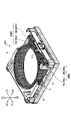
- FIG. 1A and 1B are perspective views of the lens driving device 101.
- FIG. 1A is a perspective view of the entire lens driving device 101
- FIG. 1B is a perspective view of the lens driving device 101 with the cover member 1 removed.
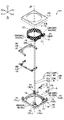
- FIG. 2 is an exploded perspective view of the lens driving device 101.
- X1 in FIG. 1A represents one direction of the X-axis constituting the three-dimensional orthogonal coordinate system, and X2 represents the other direction of the X-axis.
- Y1 represents one direction of the Y-axis forming the three-dimensional orthogonal coordinate system, and Y2 represents the other direction of the Y-axis.
- Z1 represents one direction of the Z-axis forming the three-dimensional orthogonal coordinate system, and Z2 represents the other direction of the Z-axis.
- the X1 side of the lens driving device 101 corresponds to the front side (front side) of the lens driving device 101
- the X2 side of the lens driving device 101 corresponds to the rear side (back side) of the lens driving device 101. do.
- the Y1 side of the lens driving device 101 corresponds to the left side of the lens driving device 101, and the Y2 side of the lens driving device 101 corresponds to the right side of the lens driving device 101.
- FIG. The Z1 side of the lens driving device 101 corresponds to the upper side of the lens driving device 101 , and the Z2 side of the lens driving device 101 corresponds to the lower side of the lens driving device 101 .
- the lens driving device 101 includes a fixed side member FB and a movable side member MB, as shown in FIG.
- the fixed side member FB includes a cover member 1 and a base member 7 .
- the movable side member MB includes a lens holding member 2 and a link mechanism LM.
- the movable-side member MB is configured to be guided in the optical axis direction by the guide mechanism GM.
- the optical axis direction includes the direction of the optical axis JD with respect to the lens body and the direction parallel to the optical axis JD. Further, the movable-side member MB is configured to be moved in the optical axis direction by the piezoelectric drive section PD.
- the cover member 1 is configured to cover the movable side member MB.
- the cover member 1 is produced by subjecting a metal plate to punching, drawing, and the like.
- the cover member 1 may be made of another material such as synthetic resin.
- the cover member 1 includes a rectangular tubular outer peripheral wall portion 1A and a flat plate-shaped and and a rectangular ring-shaped ceiling portion 1B.
- a circular opening 1K is formed in the central portion of the ceiling portion 1B.
- the cover member 1 has a box-like outer shape that defines the housing portion 1S, and is configured so that the movable side member MB can be housed in the housing portion 1S.
- the cover member 1 is joined to the base member 7 with an adhesive, and together with the base member 7 constitutes the housing HS.
- the lens holding member 2 is configured so that the cylindrical portion 2C can hold a lens body (not shown).
- the lens holding member 2 is made by injection molding synthetic resin such as liquid crystal polymer (LCP).
- LCP liquid crystal polymer
- a lens body is, for example, a cylindrical lens barrel with at least one lens.
- the link mechanism LM is an example of a regulation mechanism.
- the regulation mechanism is arranged between the lens holding member 2 and the fixed side member FB, and is a mechanism for suppressing a change in posture when the lens holding member 2 moves in the optical axis direction.
- a change in the posture of the lens holding member 2 includes, for example, an inclination of the optical axis JD with respect to the Z-axis direction.
- the link mechanism LM includes a first link member 3 and a second link member 4, and is arranged between the lens holding member 2 and the base member 7 as the fixed side member FB. It is configured to be able to suppress a change in posture when moving in the optical axis direction.
- the piezoelectric drive unit PD is configured to move the lens holding member 2 along the optical axis direction.
- the piezoelectric drive PD is an example of a friction drive utilizing the drive system disclosed in U.S. Pat. include.
- the piezoelectric element 8 is configured to be able to realize bending vibration according to the applied voltage.
- the piezoelectric element 8 extends in the Y-axis direction perpendicular to the optical axis direction (the direction perpendicular to the optical axis JD), and can realize bending vibration having two nodes.
- the piezoelectric element 8 has a two-layer structure composed of a first layer for realizing a first bending vibration on the XY plane and a second layer for realizing a second bending vibration on the YZ plane.
- the piezoelectric driving part PD applies voltage to the piezoelectric elements forming the first layer and applying voltage to the piezoelectric elements forming the second layer separately at appropriate timings, so that the midpoint of the piezoelectric element 8 is
- the trajectory drawn by can be a circular trajectory centered on the rotation axis 8X.
- the rotation axis 8X is parallel to the Y-axis.
- Piezoelectric drive unit PD can switch the moving direction (rotating direction) of the middle point following the circular orbit between clockwise and counterclockwise when viewed from the Y1 side by applying voltage at appropriate timing. can.
- the lens holding member 2 is moved upward (Z1 direction) when the rotating direction of the midpoint of the piezoelectric element 8 is clockwise, and downward (Z2 direction) when the rotating direction of the midpoint of the piezoelectric element 8 is counterclockwise. direction).
- the midpoint of the piezoelectric element 8 is the point where the amplitude of the first bending vibration is maximum (the point corresponding to the antinode of the first bending vibration) and the point where the amplitude of the second bending vibration is maximum (the second point corresponding to the antinode of bending vibration).
- the piezoelectric element 8 in the present embodiment is configured so as to realize vibration (circular motion) such that its midpoint draws a circle.
- the circle (orbit) drawn by the midpoint of the piezoelectric element 8 may not be a perfect circle (perfect circle), but may have a substantially circular shape.
- the contact member 9 is attached to the piezoelectric element 8 and configured to come into contact with the lens holding member 2 .
- the contact member 9 is bonded to the inner surface of the piezoelectric element 8 with an adhesive so as to cover the entire inner surface (the side facing the optical axis JD) of the piezoelectric element 8 .
- the contact member 9 is made of a magnetic material.
- the material having magnetism is, for example, metal, ceramics, rubber, synthetic resin, or the like.
- the contact member 9 may be a magnet.
- the contact member 9 is configured to perform bending vibration according to the bending vibration of the piezoelectric element 8 .
- the contact member 9 is a friction plate made of stainless steel.
- the contact member 9 extends in the same Y-axis direction as the piezoelectric element 8 extends.
- the contact member 9 is configured such that the central portion in the extending direction contacts the receiving member 11 attached to the lens holding member 2 .
- the contact member 9 is configured to contact the receiving member 11 at a point (an antinode portion of the bending vibration) where the amplitude of the bending vibration is maximum.
- the receiving member 11 is made of a magnetic material.
- the material having magnetism is, for example, metal, ceramics, rubber, synthetic resin, or the like.
- the receiving member 11 is a metal magnet that is dipole-magnetized in the optical axis direction.
- the receiving member 11 is a cylindrical pin extending in the optical axis direction.
- the receiving member 11 may be a member having a shape other than a cylindrical shape, such as a semi-cylindrical shape or an elliptical cylindrical shape, as long as point contact is realized between the contact member 9 and the receiving member 11. .
- the contact member 9 made of metal and the receiving member 11 made of metal are brought into contact with the lens holding member 2 made of synthetic resin and the contact member made of metal which is significantly harder (higher wear resistance) than the lens holding member 2.
- the receiving member 11 is made of stainless steel and configured to have a surface hardness higher than that of the contact member 9 . This is because the higher the surface hardness, the less likely abrasion powder is generated. This is also to prevent the smooth bending vibration of the contact member 9 from being hindered. This is because it is desirable that the contact member 9 have a relatively low surface hardness so that the bending vibration can be smoothly performed. However, if excessive generation of abrasion powder originating from the contact member 9 and the receiving member 11 can be suppressed, the surface hardness of the receiving member 11 is configured to be substantially the same as the surface hardness of the contact member 9. The surface hardness of the contact member 9 may be lower than that of the contact member 9 . Further, the receiving member 11 may be subjected to nitriding treatment (surface hardening treatment) such as salt bath soft nitriding treatment.
- nitriding treatment surface hardening treatment
- the length dimension of the contact member 9 in the Y-axis direction does not have to be the same as that of the piezoelectric element 8 as long as contact between the contact member 9 and the receiving member 11 can be obtained.
- the circuit board 10 is a board including a conductive pattern, and is configured to electrically connect an external control device having a voltage applying function and the piezoelectric element 8 .
- the circuit board 10 is a flexible printed board having flexibility, and is configured to apply a voltage to the piezoelectric element 8 .
- the piezoelectric element 8 is bonded to the inner surface (the side facing the optical axis JD) of the circuit board 10 with an anisotropic conductive adhesive.
- the piezoelectric element 8 may be bonded inside the circuit board 10 with an anisotropic conductive adhesive film.
- the piezoelectric drive part PD is configured to be biased inwardly (in a direction approaching the optical axis JD) by a biasing member 6 fixed to the base member 7 and pressed against the lens holding member 2 .
- the biasing member 6 is formed of a metal plate, and is positioned outside the piezoelectric element 8 (far from the optical axis JD) at portions corresponding to two nodes formed when the piezoelectric element 8 undergoes bending vibration. side) and the circuit board 10 are in contact with each other.
- the bonding between the urging member 6 and the piezoelectric driving part PD is achieved by, for example, an adhesive.
- the guide mechanism GM is configured to be able to guide the lens holding member 2 movably in the optical axis direction with respect to the fixed side member FB.
- the guide mechanism GM includes a movable groove portion 2G formed in the columnar portion 2B of the lens holding member 2, a fixed groove portion 7G formed in the columnar portion 7B of the base member 7, and a movable groove portion 2G. and a ball 5 sandwiched between the fixed side groove portion 7G.
- the columnar portion 2B of the lens holding member 2 includes a left columnar portion 2BL and a right columnar portion 2BR
- the movable groove portion 2G includes a left movable groove portion 2GL and a right columnar portion 2BR formed in the left columnar portion 2BL. It includes a right movable side groove portion 2GR formed in.
- the guide mechanism GM has two guide portions (a right guide portion GMR and a left guide portion GML) arranged to face each other with the receiving member 11 attached to the lens holding member 2 interposed therebetween.
- the right guide portion GMR includes a right movable groove portion 2GR formed in the right columnar portion 2BR of the lens holding member 2, a right fixed groove portion 7GR formed in the right columnar portion 7BR of the base member 7, and a right movable groove portion 2GR. and a right side ball 5R arranged between the right fixed side groove portion 7GR.
- the right ball 5R includes an upper right ball 5RU and a lower right ball 5RD.
- the left guide portion GML includes a left movable groove portion 2GL formed in the left columnar portion 2BL of the lens holding member 2, a left fixed groove portion 7GL formed in the left columnar portion 7BL of the base member 7, and a left movable groove portion 2GL. and the left side ball 5L disposed between the left fixed side groove portion 7GL.
- the left ball 5L includes an upper left ball 5LU and a lower left ball 5LD.
- the base member 7 is manufactured by injection molding using synthetic resin such as liquid crystal polymer.
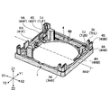
- the base member 7 has a substantially rectangular plate-like outer shape, and a circular opening 7K is formed in the center.
- the subject-side (Z1 side) surface (upper surface) of the base member 7 there are provided two rectangular convex columnar portions 7B projecting upward and one rectangular convex wall portion 7W.
- Two corners on the front side of the base member 7 are formed with holding portions 7C that protrude upward, and two corners on the rear side of the base member 7 are formed with third grip portions that protrude upward.
- a shaft support portion 7H is formed.
- the clamping portion 7C is a portion configured to clamp the biasing member 6, and includes a left clamping portion 7CL and a right clamping portion 7CR.
- the third shaft support portion 7H is a portion configured to support the third shaft portion 3S of the first link member 3, and includes a left third shaft support portion 7HL and a right third shaft support portion 7HR. Further, at the left front corner and the left rear corner of the base member 7, as shown in FIG. 3C, a fourth shaft supporting portion 7J is formed.
- the fourth shaft support portion 7J is a portion configured so that at least the right side (Y2 side) is open so as to support the fourth shaft portion 4S of the second link member 4. Includes 4-axis support 7JB.
- a sensor 12 is attached to the wall portion 7W of the base member 7. Specifically, the sensor 12 mounted on the sensor circuit board 14 is attached to the rear surface (the surface on the X2 side) of the wall portion 7W so as to face the magnet 13 attached to the lens holding member 2. .
- the sensor 12 is connected to an external controller CTR (see FIG. 17) via a sensor circuit board 14 (see FIG. 11B).
- the sensor 12 is configured to detect the position of the movable side member MB.
- the sensor 12 is composed of a Hall element, measures an output voltage that changes according to the magnitude of the magnetic field generated by the magnet 13 received by the sensor 12, and measures the output voltage of the movable side member MB (lens holding member 2 ) is configured to detect the position of
- the sensor 12 is a giant magneto resistive effect (GMR) element, a semiconductor magneto resistive (SMR) element, an anisotropic magneto resistive (AMR) element, or a tunnel magneto resistance (Tunnel Magneto Resistive: TMR) element or other magnetoresistive element may be used to detect the position of the movable side member MB.
- GMR giant magneto resistive effect
- SMR semiconductor magneto resistive
- AMR anisotropic magneto resistive
- TMR tunnel magneto resistance
- the lens driving device 101 has a substantially rectangular parallelepiped outer shape and is mounted on a substrate (not shown) on which an imaging device (not shown) is mounted.
- the substrate, the lens driving device 101, the lens body (not shown) attached to the lens holding member 2, and the imaging device mounted on the substrate so as to face the lens body constitute a camera module.
- the piezoelectric element 8 is connected to an external control device CTR via the circuit board 10 . When a voltage is applied to the piezoelectric element 8, the piezoelectric element 8 performs a first bending vibration and a second bending motion, and generates force to move the lens holding member 2 along the optical axis direction. This force is a friction force associated with contact between the receiving member 11 attached to the lens holding member 2 and the contact member 9 joined to the piezoelectric element 8 .
- the lens driving device 101 utilizes this force to move the lens holding member 2 along the optical axis direction on the Z1 side (object side) of the imaging element, thereby realizing an automatic focus adjustment function. Specifically, the lens driving device 101 moves the lens holding member 2 away from the image pickup device to enable macro photography, and moves the lens holding member 2 toward the image pickup device to enable infinity photography. I have to.
- FIGS. 3A to 3C are views of the base member 7 with the link mechanism LM attached.
- FIG. 3A is a top view of the lens holding member 2 and the base member 7 with the link mechanism LM attached
- FIG. 3B is a top view of the lens holding member 2 and the base member 7 with the link mechanism LM attached.
- FIG. 3C is a left side view of the base member 7, and
- FIG. 3C is a perspective view of the base member 7 with only the second link member 4 attached.
- FIG. 3A to 3C all show the state when the lens holding member 2 movable in the optical axis direction is positioned at the lowest side (Z2 side).
- 4A to 4C, 5A, and 5B are diagrams of the lens holding member 2 with the link mechanism LM attached. Specifically, FIG. 4A is a perspective view of the lens holding member 2 with the link mechanism LM attached, and FIGS. 4B and 4C are left side views of the lens holding member 2 with the link mechanism LM attached. It is a plan view. 5A and 5B are front views of the lens holding member 2 with the link mechanism LM attached. 4A and 4B show the state when the lens holding member 2 is positioned at the lowermost side (Z2 side), and FIG.
- FIG. 4C shows the state when the lens holding member 2 is positioned at the uppermost side (Z1 side). show the situation.
- 5A shows the state when the lens holding member 2 is positioned at the lowest side (Z2 side)
- FIG. 5B shows the state when the lens holding member 2 is positioned at the highest side (Z1 side). .
- the link mechanism LM has a first link member 3 and a second link member 4.
- the first link member 3 and the second link member 4 are made by injection molding synthetic resin such as liquid crystal polymer (LCP).
- the first link member 3 is connected to the lens holding member 2 so as to be rotatable about the first rotation axis RA1, and the second link member 4 is rotatable about the second rotation axis RA2. It is connected to the lens holding member 2 so that it becomes.
- the first link member 3 is connected to the base member 7 so as to be rotatable about a third rotation axis RA3, and the second link member 4 is rotatable about a fourth rotation axis RA4. It is connected to the base member 7 so as to be possible.
- the first rotation axis RA1 and the third rotation axis RA3 are arranged parallel to each other, and the second rotation axis RA2 and the fourth rotation axis RA4 are arranged parallel to each other.
- each of the first rotation axis RA1 and the third rotation axis RA3 and each of the second rotation axis RA2 and the fourth rotation axis RA4 are orthogonal to each other. are placed.
- the first rotation axis RA1 and the second rotation axis RA2 are arranged so as to be orthogonal to each other at the position of the optical axis JD, and the third rotation axis
- the RA3 and the fourth rotation shaft RA4 are arranged so as to be perpendicular to each other at the left rear corner of the base member 7 .
- the first rotation axis RA1 and the second rotation axis RA2 are orthogonal to the optical axis direction.
- the lens holding member 2 includes a pair of first shaft portions 2S (a left first shaft portion 2SL and a right first shaft portion 2SR) and a pair of second shaft portions. 2T (front second shaft portion 2TF and rear second shaft portion 2TB).
- the first link member 3 is formed with a pair of third shaft portions 3S (left third shaft portion 3SL and right third shaft portion 3SR) rotatably supported by the base member 7. and a pair of first arm portions 3A (left first arm portion 3AL and right first arm portion 3AR) connected to the first base portion 3B and facing each other.
- a first shaft support portion 3H (a left first shaft support portion 3HL and a right first shaft support portion 3HR) is formed at the tip of each of the pair of first arm portions 3A.
- the left first shaft support portion 3HL supports the left first shaft portion 2SL formed on the lens holding member 2
- the right first shaft support portion 3HR supports the right side shaft portion formed on the lens holding member 2.
- the left third shaft portion 3SL is supported by a left third shaft support portion 7HL formed at the left rear corner of the base member 7, and the right third shaft portion 3SR is supported by the base member 7.
- the member 7 is supported by a right third pivot portion 7HR formed at a right rear corner portion.
- the second link member 4 is formed with a pair of fourth shaft portions 4S (fourth front shaft portion 4SF and fourth rear shaft portion 4SB) rotatably supported by the base member 7. and a pair of second arms 4A (front second arm 4AF and rear second arm 4AB) connected to the second base 4B and facing each other.
- a second shaft support portion 4H (a front side second shaft support portion 4HF and a rear side second shaft support portion 4HB) is formed at the tip of each of the pair of second arm portions 4A.
- the front second shaft portion 4HF supports the front second shaft portion 2TF (see FIG. 8A) formed on the lens holding member 2
- the rear second shaft portion 4HB supports the rear second shaft portion 4HB formed on the lens holding member 2.
- the front fourth shaft portion 4SF is supported by a front fourth shaft support portion 7JF formed at the left front corner of the base member 7, and the rear fourth shaft portion 4SB is supported by the base member 7. It is supported by a rear fourth pivotal support portion 7JB formed at the left rear corner of the member 7 .
- the lens holding member 2 and the first link member 3 are connected via the first shaft portion 2S and the first shaft support portion 3H, and the lens holding member 2 and the second link member 4 are connected by They are connected via the two shaft portions 2T and the second shaft support portion 4H.
- the first shaft support portion 3H has a U-shaped first concave portion UR1 with an open front side (X1 side).
- the first shaft portion 2S is located inside the first recess portion UR1 and is configured such that a gap D1 can be formed between the inner bottom surface of the first recess portion UR1 and the first shaft portion 2S.
- the second shaft supporting portion 4H has a U-shaped second concave portion UR2 that is open on the right side (Y2 side).
- the second shaft portion 2T is located inside the second recess portion UR2, and is configured such that a gap D2 can be formed between the inner bottom surface of the second recess portion UR2 and the second shaft portion 2T.
- the link mechanism LM is configured such that the sizes of the gaps D1 and D2 change when the lens holding member 2 moves along the optical axis direction. This is to prevent the posture of the lens holding member 2 from changing when the lens holding member 2 moves along the optical axis direction.
- the link mechanism LM is configured such that the size of the gap D1 becomes smaller when the lens holding member 2 moves upward (Z1 direction).
- the link mechanism LM is configured such that the size of the gap D2 becomes smaller when the lens holding member 2 moves upward (Z1 direction).
- FIGS. 6A, 6B, 7A, 7B, 8A, 8B, 9A, 9B, 10A, and 10B are perspective views of the lens driving device 101 with the cover member 1 removed. Specifically, FIG. 6A shows the state when the lens holding member 2 is positioned at the lowermost side (Z2 side), and FIG. 6B shows the state when the lens holding member 2 is positioned at the uppermost side (Z1 side). show the situation. 7A and 7B are perspective views of the entire base member 7. FIG. Specifically, FIG. 7A shows a state in which the ball 5 is not installed in the stationary groove 7G formed in the columnar portion 7B of the base member 7, and FIG.
- FIG. 8A and 8B are perspective views of the base member 7.
- FIG. 8A is an overall perspective view of the base member 7 to which the lens holding member 2 and the ball 5 are attached.
- FIG. 8B is an enlarged view of range R1 surrounded by a dashed line shown in FIG. 8A.
- illustration of members other than the base member 7 is omitted for clarity.
- 9A and 9B are perspective views of the lens holding member 2.
- FIG. 9A is a perspective view of the entire lens holding member 2 attached to the base member 7.
- FIG. 9B is an enlarged view of range R2 surrounded by a dashed line shown in FIG. 9A.
- FIG. 9A is a perspective view of the entire lens holding member 2 attached to the base member 7.
- FIG. 9B is an enlarged view of range R2 surrounded by a dashed line shown in FIG. 9A.
- FIG. 10A shows a state in which the ball 5 is not installed in the movable groove portion 2G formed in the columnar portion 2B of the lens holding member 2, and FIG. is installed.
- the guide mechanism GM has a receiving member in the left-right direction (Y-axis direction). It includes a right guide portion GMR and a left guide portion GML that are arranged to face each other with the 11 therebetween.
- the right guide portion GMR faces the right movable groove portion 2GR (see FIG. 10A) provided in the right columnar portion 2BR of the lens holding member 2 and the right movable groove portion 2GR provided in the base member 7. and a right ball 5R (see FIG. 7B) disposed between the right movable groove 2GR and the right fixed groove 7GR.
- the right fixed groove 7GR is divided into two recesses 7V as shown in FIG. 7A.
- the recess 7V includes an upper right recess 7VRU and a lower right recess 7VRD.
- the right ball 5R includes an upper right ball 5RU accommodated in the upper right recess 7VRU and a lower right ball 5RD accommodated in the lower right recess 7VRD.
- the right movable groove portion 2GR is not divided into two recesses and extends continuously in the optical axis direction (Z-axis direction).
- the upper right ball 5RU and the lower right ball 5RD do not approach each other and are maintained at a predetermined distance even when the lens holding member 2 moves along the optical axis direction. be. This is because the movement of the upper right ball 5RU and the lower right ball 5RD in the optical axis direction is restricted by the upper right recess 7VRU and the lower right recess 7VRD.
- the left guide portion GML includes a left movable groove portion 2GL (see FIG. 10A) provided in the left columnar portion 2BL of the lens holding member 2 and a left movable groove portion 2GL provided in the base member 7 and facing the left movable groove portion 2GL. It has a fixed groove portion 7GL (see FIG. 7A) and a left ball 5L (see FIG. 7B) arranged between the left movable groove portion 2GL and the left fixed groove portion 7GL.
- the left fixed groove 7GL is divided into two recesses 7V as shown in FIG. 8B.
- the recess 7V includes an upper left recess 7VLU and a lower left recess 7VLD.
- the left ball 5L includes an upper left ball 5LU accommodated in the upper left recess 7VLU and a left lower ball 5LD accommodated in the left lower recess 7VLD.
- the left movable side groove portion 2GL is not divided into two concave portions and extends continuously in the optical axis direction (Z-axis direction).
- the upper left ball 5LU and the lower left ball 5LD do not come close to each other even when the lens holding member 2 moves along the optical axis, leaving a predetermined gap as shown in FIG. 10B. maintained as it was. This is because the left upper ball 5LU and the left lower ball 5LD are restricted in movement in the optical axis direction by the upper left concave portion 7VLU and the left lower concave portion 7VLD.
- the lens driving device 101 can smoothly move the lens holding member 2 along the optical axis direction. Further, by providing the link mechanism LM as described above, the lens driving device 101 can prevent the lens holding member 2 from tilting when the lens holding member 2 moves along the optical axis direction. .
- FIGS. 11A, 11B, 12A, 12B, 13A to 13D, 14A to 14D, 15A, 15B, 16A, and 16B details of the piezoelectric drive section PD will be described.
- 11A and 11B are perspective views of the lens driving device 101 with the cover member 1 removed.
- FIG. 11A is a perspective view of the lens driving device 101 with the piezoelectric driving section PD and the biasing member 6 further removed.
- FIG. 11B is an enlarged view of range R3 surrounded by a dashed line shown in FIG. 11A.
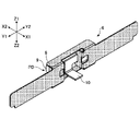
- 12A and 12B are perspective views of the piezoelectric driver PD.
- FIG. 12A is a perspective view of the entire piezoelectric drive section PD
- FIG. 12B is an exploded perspective view of the piezoelectric drive section PD
- 13A-13D are detailed views of the biasing member 6.
- FIG. 13A is a perspective view of the biasing member 6
- FIG. 13B is a front view of the biasing member 6
- FIG. 13C is a top view of the biasing member 6
- FIG. 6 is a left side view of FIG. 14A-14D are detailed views of the biasing member 6 to which the piezoelectric drive PD is attached, and correspond to FIGS. 13A-13D
- FIG. 14A is a perspective view of the biasing member 6 to which the piezoelectric drive part PD is attached, and corresponds to FIG.
- FIG. 14B is a front view of the biasing member 6 to which the piezoelectric drive part PD is attached, and corresponds to FIG. 13B.
- FIG. 14C is a top view of the biasing member 6 to which the piezoelectric drive part PD is attached, and corresponds to FIG. 13C.
- FIG. 14D is a left side view of the biasing member 6 to which the piezoelectric drive part PD is attached, and corresponds to FIG. 13D.
- 15A and 15B are views of the biasing member 6 to which the piezoelectric drive PD is attached via the adhesive AD. Specifically, FIG. 15A is an enlarged view of range R4 surrounded by broken lines shown in FIG. 14B.
- FIG. 15A is an enlarged view of range R4 surrounded by broken lines shown in FIG. 14B.
- FIG. 15B is a left side view of the biasing member 6 to which the piezoelectric driving part PD is attached via the adhesive AD, and corresponds to FIGS. 13D and 14D.
- 16A and 16B are views of the base member 7 with the biasing member 6 attached. Specifically, FIG. 16A is an overall perspective view of the base member 7 to which the biasing member 6 is attached.
- FIG. 16B is an enlarged top view of range R5 surrounded by broken lines shown in FIG. 16A.
- the biasing member 6 is configured by a leaf spring member. Specifically, as shown in FIGS. 13A to 13D, the biasing member 6 includes a fixed portion 6F fixed to the base member 7, a support portion 6S supporting the piezoelectric drive portion PD, and a fixed portion 6F and a supporting portion 6F. and an elastically deformable elastically deformable portion 6E provided between the portion 6S.
- the fixing part 6F includes a left fixing part 6FL and a right fixing part 6FR
- the support part 6S includes a left support part 6SL and a right support part 6SR.
- the left elastic deformation portion 6EL is provided between the left fixing portion 6FL and the left support portion 6SL
- the right elastic deformation portion 6EL is provided between the right fixing portion 6FR and the right support portion 6SR. and part 6ER.
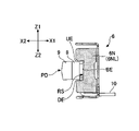
- the support portion 6S has a plate-like base portion 6B connected to the elastic deformation portion 6E, and a bent portion 6N that is bent in an L shape from the base portion 6B and protrudes toward the side (X2 side) where the lens holding member 2 is positioned.
- a concave portion RS (see FIG. 13D) is formed at the tip of the bent portion 6N.
- the recess RS is a recess that is open on the side where the lens holding member 2 is located.
- the base 6B includes a left base 6BL that is part of the left support 6SL and a right base 6BR that is part of the right support 6SR.
- the bent portion 6N includes a left bent portion 6NL that is part of the left support portion 6SL and a right bent portion 6NR that is part of the right support portion 6SR.
- the recesses RS are formed in the same shape and size at the respective ends of the left bent portion 6NL and the right bent portion 6NR.
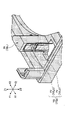
- the piezoelectric drive portion PD is partially positioned within the recess RS and is in contact with the inner edge portion BE of the recess RS. It is fixed at 6N.
- a gap is shown between the bent portion 6N and the piezoelectric drive portion PD (circuit board 10). It is in contact with the part PD (circuit board 10).
- the recess RS has an upper edge UE and a lower edge DE facing each other across the inner edge BE.
- the piezoelectric drive part PD is arranged between the upper edge UE and the lower edge DE.
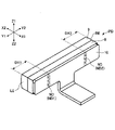
- the position at which the inner edge portion BE of the recess RS contacts the piezoelectric drive part PD corresponds to the node position ND of the piezoelectric drive part PD that realizes bending vibration, as shown in FIG. 12A.
- the node positions ND include a first position ND1 and a second position ND2. In FIG. 12A, the node positions ND are marked with a cross pattern for clarity.
- the position at which the inner edge portion BE of the recess RS contacts the piezoelectric drive portion PD corresponds to a position at a predetermined distance from the end of the piezoelectric drive portion PD.
- the predetermined distance is, for example, approximately a quarter of the total length of the piezoelectric drive part PD. That is, the first position ND1, which is one of the positions where the inner edge portion BE of the recess RS and the piezoelectric driving portion PD contact each other, is located at the distance DX1 from the left end portion LE of the piezoelectric driving portion PD.
- the distance DX1 is approximately one quarter of the total length (length in the Y-axis direction) of the piezoelectric drive section PD.
- the second position ND2 which is another one of the positions where the inner edge portion BE of the recess RS and the piezoelectric driving portion PD contact each other, is located at a distance DX2 from the right end portion RE of the piezoelectric driving portion PD. .
- the distance DX2 is approximately a quarter of the total length of the piezoelectric drive section PD.
- the piezoelectric drive part PD and the bent part 6N are fixed with an adhesive AD, as shown in FIGS. 15A and 15B.
- the adhesive AD is an ultraviolet curable adhesive.
- the adhesive AD may be other types of adhesive such as moisture-curing or heat-curing.
- the adhesive AD adheres between one surface of the bent portion 6N and the piezoelectric drive portion PD and between the other surface of the bent portion 6N and the piezoelectric drive portion PD.
- the adhesive AD is applied to the first position ND1 and the second position ND2 on the surface of the front side (X1 side) of the circuit board 10, as shown in FIG. 12A. That is, the adhesive AD includes the adhesive AD applied to the first position ND1 and the adhesive AD applied to the second position ND2. Further, the biasing member 6 is pressed against the front surface of the circuit board 10 so that the adhesive AD applied to the front surface of the circuit board 10 is crushed by the concave portion RS provided at the tip of the bent portion 6N.
- the adhesive AD applied to the first position ND1 is the adhesive AD1L that adheres between the left side surface of the left bent portion 6NL and the piezoelectric drive portion PD, and the adhesive AD1L that adheres between the left bent portion 6NL and the left bent portion 6NL and the adhesive AD1R that adheres between the right side surface of and the piezoelectric drive part PD.
- the adhesive AD applied to the second position ND2 includes an adhesive AD2L that adheres between the left side surface of the right bent portion 6NR and the piezoelectric drive portion PD, and an adhesive AD2L that adheres between the right side surface of the right bent portion 6NR and the piezoelectric drive portion. It is divided into the adhesive AD2R that adheres between the PD.
- the two elastic deformation portions 6E extend away from the corresponding base portion 6B.
- the left elastic deformation portion 6EL extends leftward (Y1 direction) from the left base portion 6BL
- the right elastic deformation portion 6ER extends rightward (Y2 direction) from the right base portion 6BR.
- the extending direction of the elastic deformation portion 6E is along the Y-axis direction, which is the extending direction of the piezoelectric element 8, as shown in FIG. 14C.
- a fixed portion 6F is provided on the extension line of the elastic deformation portion 6E.
- the fixed portion 6F is sandwiched by a sandwiching portion 7C provided on the base member 7, as shown in FIG. 16B.
- the holding portion 7C includes a columnar protrusion PL extending upward (in the Z1 direction) from the upper surface of the base member 7, and an L-shaped corner wall portion formed at a corner portion of the base member 7 in plan view.
- the fixing portion 6F of the biasing member 6 is fitted between the projection PL and the corner wall portion CN from above, thereby being sandwiched between the projection PL and the corner wall portion CN.
- the clamping of the fixing portion 6F by the clamping portion 7C may be realized by an adhesive or may be reinforced by the adhesive.
- an opening 6H is formed in the base portion 6B of the biasing member 6, as shown in FIGS. 13A and 13B.
- the opening 6H includes a left opening 6HL formed in the left base portion 6BL of the left support portion 6SL and a right opening 6HR formed in the right base portion 6BR of the right support portion 6SR.
- the left opening 6HL is formed so that the connection state between the left bent portion 6NL and the piezoelectric driving portion PD can be visually recognized from the front side (X1 side).
- the connection state is, for example, whether or not the adhesive AD1L is properly arranged.
- the right opening 6HR is formed so that the connection state between the right bent portion 6NR and the piezoelectric driving portion PD can be visually recognized from the front side (X1 side).
- the connection state is, for example, whether or not the adhesive AD2R is properly arranged.
- the biasing member 6 has a connecting portion 6C that connects two base portions 6B. Specifically, as shown in FIGS. 13A and 13B, the biasing member 6 has an upper connecting portion 6CU and a lower connecting portion 6CD that connect the left base portion 6BL and the right base portion 6BR.
- FIG. 17 is a block diagram showing a configuration example of the camera module CM.
- illustration of some members constituting the camera module CM is omitted for clarity.
- the camera module CM mainly includes a substrate (not shown), a lens driving device 101 including a lens holding member 2, a lens body (not shown) attached to the lens holding member 2, and a It includes an imaging device IM mounted on a substrate so as to face each other, and a control device CTR configured to drive a piezoelectric driving section PD to move the lens holding member 2 in the optical axis direction.
- control device CTR is mounted on the board on which the lens driving device 101 and the imaging device IM are mounted.
- control device CTR may be provided inside the housing HS that constitutes the lens driving device 101, and a separate substrate outside the housing HS (on which the lens driving device 101 and the image sensor IM are mounted). It may be mounted on a board different from the board on which it is mounted.
- the control device CTR is composed of a computer including a CPU, a volatile memory device, a non-volatile memory device, and the like. Then, the control device CTR reads a program corresponding to each function from the nonvolatile storage device, loads it into the volatile storage device, and causes the CPU to execute the corresponding process.
- Each function is, for example, an automatic focus adjustment function, a cleaning function, and the like.
- the processes corresponding to the automatic focus adjustment function and the cleaning function are a process of moving the lens holding member 2 upward in a direction away from the image sensor IM, and a process of moving the lens holding member 2 downward in a direction to approach the image sensor IM. and a process of stopping the lens holding member 2 at the current position.
- the control device CTR may be composed of an ASIC, an FPGA, or the like.
- control device CTR is configured to receive a signal output from the sensor 12 and detect the position (height) of the lens holding member 2 in the Z-axis direction (optical axis direction) based on the signal. It is Further, the control device CTR applies a voltage to the piezoelectric element 8 constituting the piezoelectric driving unit PD via the circuit board 10 to vibrate the piezoelectric element 8, thereby moving the lens holding member 2 in the vertical direction (optical axis direction). direction).
- control device CTR is configured to be able to switch the operation mode of the lens driving device 101 between at least the normal mode and the cleaning mode.
- the normal mode is an operation mode that is selected when the camera function is used in the mobile device on which the camera module CM is installed.
- the normal mode is selected over a period from when the use of the camera function is started until when the use of the camera function is finished.
- the normal mode is selected over a period from when an operation to activate the camera function is performed to when an operation to stop the camera function is performed.
- the cleaning mode is an operation mode that is selected when removing abrasion powder present within the first contact area from the first contact area.
- the first contact range is a range on the surface of the receiving member 11 that can be contacted by the contact member 9 when the normal mode is selected. Since the wear powder originates from the contact member 9 made of a magnetic member or the receiving member 11 which is a magnet, that is, it has magnetism, it does not fall from the contact portion between the contact member 9 and the receiving member 11. It is magnetically attracted to the surface of the receiving member 11 .
- the contact member 9 pushes away the abrasion powder adsorbed within the first contact range to the outside of the first contact range within the second contact range.
- the second contact range is a range on the surface of the receiving member 11 that can be contacted by the contact member 9 when the cleaning mode is selected, is wider than the first contact range, and completely includes the first contact range. ing.
- the cleaning mode is preferably selected when predetermined initiation conditions are met.
- the predetermined start condition is, for example, that the power of the camera module CM has been turned on, that an operation has been performed to activate the camera function, that an operation has been performed to stop the camera function, or that the cleaning function has been activated. For example, an operation has been performed.
- the cleaning mode may be selected when the elapsed time since the last cleaning function was performed exceeds a preset period of time and when a predetermined start condition is met. That is, even if the predetermined start condition is satisfied, the cleaning mode is not selected if the elapsed time since the previous cleaning function was executed has not reached the preset period. good too.
- the cleaning function is a function for pushing out the wear particles within the first contact range outside the first contact range.
- the cleaning function includes at least a function of moving the lens holding member 2 to the upper limit of the second contact range and a function of moving the lens holding member 2 to the lower limit of the second contact range.
- the cleaning mode selected when the operation to activate the camera function is performed is switched to the normal mode when the cleaning function is completed.
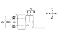
- FIGS. 18A1, 18A2, 18B1, and 18B2 are diagrams showing the positional relationship between the piezoelectric driving part PD and the receiving member 11 when the cleaning function is performed.
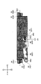
- FIG. 18A1 is a front view of the receiving member 11, and FIG. 18A2 is a left side view of the piezoelectric driving part PD and the receiving member 11.
- FIG. FIG. 18B1 is a front view of a receiving member 11A, which is another configuration example of the receiving member 11, and FIG. 18B2 is a left side view of the piezoelectric driving part PD and the receiving member 11A.
- the receiving member 11A differs from the receiving member 11, which is a magnet that is dipole-magnetized in the Z-axis direction, which is the optical axis direction, in that it is a magnet that is dipole-magnetized in the X-axis direction.
- a cross pattern is given to the N pole portion, and a dot pattern is given to the S pole portion.
- FIG. 19 is a flowchart showing an example of the flow of processing for determining whether or not to execute the cleaning function (hereinafter referred to as "determination processing").
- the control device CTR repeatedly executes this determination process at a predetermined control cycle.
- FIG. 20A to 20E are left side views of the piezoelectric drive part PD and the receiving member 11, and the contact point CP between the piezoelectric drive part PD (contact member 9) and the receiving member 11 when the cleaning function is performed. shows the position of Specifically, FIG. 20A shows the state of the piezoelectric driving part PD and the receiving member 11 when the contact point CP is located at the center CL of the first contact range MS1, and FIG. FIG. 20C shows the state of the piezoelectric driving part PD and the receiving member 11 when the contact point CP is at the upper limit UM1 of the first contact range MS1. Indicates status.
- FIG. 20D shows the state of the piezoelectric driving part PD and the receiving member 11 when the contact point CP is at the lower limit DM2 of the second contact range MS2, and FIG. 20E shows the state of the contact point CP at the upper limit of the second contact range MS2.
- the state of the piezoelectric drive part PD and the receiving member 11 when in UM2 is shown.
- the lower limit DM1 corresponds to the position closest to the image sensor IM within the first contact range MS1
- the upper limit UM1 corresponds to the position farthest from the image sensor IM within the first contact range MS1.
- the lower limit DM2 corresponds to the position closest to the image sensor IM in the second contact range MS2
- the upper limit UM2 corresponds to the position farthest from the image sensor IM in the second contact range MS2.
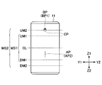
- FIGS. 21A and 21B are front views of the receiving member 11.
- the cleaning function removes wear powder AP (upper wear powder AP1 and lower wear powder AP2) within the first contact range MS1 to the outside of the first contact range MS1. It shows how it can be pushed away.
- FIG. 21A shows the state of the receiving member 11 when the contact point CP is at the center CL of the first contact range MS1
- FIG. 21C shows the state of the receiving member 11 when the contact point CP reaches the lower limit DM2 of the second contact range MS2 after that.
- the wear powder AP adsorbed to the receiving member 11 within the first contact range MS1 is represented by a dot pattern
- Wear powder BP upper side wear powder BP1 and lower side wear powder BP2
- the wear powder AP is wear powder derived from at least one of the contact member 9 and the receiving member 11 .
- the receiving member 11 is composed of a dipole magnet, the upper portion of which is magnetized to the N pole and the lower portion of which is magnetized to the S pole. Therefore, as shown in FIGS. 21A to 21C, the wear powder AP is attracted to the surface of the receiving member 11 by the magnetic force of the receiving member 11, and does not drop from the surface of the receiving member 11.
- FIG. 21A to 21C the wear powder AP is attracted to the surface of the receiving member 11 by the magnetic force of the receiving member 11, and does not drop from the surface of the receiving member 11.
- control device CTR determines whether or not conditions for starting the cleaning function are satisfied (step ST1). In this embodiment, the control device CTR determines that the conditions for starting the cleaning function are satisfied when the operator of the mobile device performs an operation to start the camera function.
- control device CTR terminates this determination process.
- the control device CTR moves the lens holding member 2 upward (step ST2).
- the control device CTR controls that the contact point CP between the piezoelectric drive portion PD (contact member 9) and the receiving member 11 is positioned at the center CL of the first contact range MS1 when the lens drive device 101 is in the initial state.
- the lens holding member 2 is positioned at the initial position so as to be positioned.
- the initial state is the state of the lens driving device 101 when the camera function is not activated.
- the initial position is the position of the lens holding member 2 when the lens driving device 101 is in the initial state.
- the control device CTR is configured to return the lens holding member 2 to the initial position when stopping the camera function.
- FIG. 20A shows the positional relationship between the piezoelectric driving portion PD (contact member 9) and the receiving member 11 when the lens driving device 101 is in the initial state.
- control device CTR is configured to move upward the lens holding member 2 that is in the initial position when the cleaning function is started.
- the control device CTR may be configured to move downward the lens holding member 2 that is in the initial position when the cleaning function is started.
- the control device CTR may determine the moving direction of the lens holding member 2 according to the current position of the lens holding member 2 .
- the control device CTR may move the lens holding member 2 downward when the current position of the lens holding member 2 is below the initial position, and the current position of the lens holding member 2 may be above the initial position. , the lens holding member 2 may be moved upward.
- the control device CTR may be configured to move the lens holding member 2 in a predetermined direction (upward or downward) regardless of the current position of the lens holding member 2 .
- the control device CTR determines whether or not the lens holding member 2 has reached the upper set position (step ST3).
- the control device CTR identifies the current position of the upwardly moving lens holding member 2 based on the output of the sensor 12 .
- the upper set position is the position of the lens holding member 2 when the contact point CP crosses the lower limit DM1 of the first contact range MS1 and reaches the lower limit DM2 of the second contact range MS2.
- a figure G1 represented by a dashed line in FIG. 18A2 shows the position of the receiving member 11 when the lens holding member 2 reaches the upper set position.
- FIG. 20B shows the state when the contact point CP reaches the lower limit DM1 of the first contact range MS1
- FIG. 20D shows the state when the contact point CP reaches the lower limit DM2 of the second contact range MS2. That is, it shows the state when the lens holding member 2 reaches the upper set position.
- control device CTR When determining that the lens holding member 2 has not reached the upper set position (NO in step ST3), the control device CTR repeats the determination of step ST3 until the lens holding member 2 reaches the upper set position.
- control device CTR moves the lens holding member 2 downward (step ST4).
- the controller CTR reverses upward movement of the lens holding member 2 to downward movement.
- the control device CTR determines whether or not the lens holding member 2 has reached the lower set position (step ST5).
- the control device CTR identifies the current position of the downwardly moving lens holding member 2 based on the output of the sensor 12 .
- the contact point CP crosses the lower limit DM1 of the first contact range MS1, crosses the center CL of the first contact range MS1, further crosses the upper limit UM1 of the first contact range MS1, and reaches the second contact range MS2. is the position of the lens holding member 2 when the upper limit UM2 of is reached.
- a figure G2 represented by a dashed line in FIG. 18A2 shows the position of the receiving member 11 when the lens holding member 2 reaches the lower set position.
- 20B shows the state when the contact point CP reaches the lower limit DM1 of the first contact range MS1
- FIG. 20A shows the state when the contact point CP reaches the center CL of the first contact range MS1.
- 20C shows the state when the contact point CP reaches the upper limit UM1 of the first contact range MS1
- FIG. 20E shows the state when the contact point CP reaches the upper limit UM2 of the second contact range MS2, That is, it shows the state when the lens holding member 2 reaches the lower set position.
- control device CTR When determining that the lens holding member 2 has not reached the lower set position (NO in step ST5), the control device CTR repeats the determination of step ST5 until the lens holding member 2 reaches the lower set position.
- control device CTR moves the lens holding member 2 upward (step ST6).
- control device CTR reverses the downward movement of the lens holding member 2 again into an upward movement.
- the control device CTR determines whether or not the lens holding member 2 has reached the central set position (step ST7).
- the control device CTR identifies the current position of the upwardly moving lens holding member 2 based on the output of the sensor 12 .
- the center set position is the position of the lens holding member 2 when the contact point CP crosses the upper limit UM1 of the first contact range MS1 and reaches the center CL of the first contact range MS1. That is, the center set position is the initial position.
- FIG. 20C shows the state when the contact point CP reaches the upper limit UM1 of the first contact range MS1, and FIG.
- the 20A shows the state when the contact point CP reaches the center CL of the first contact range MS1, that is, The state when the lens holding member 2 reaches the center set position is shown.
- the central set position may be the position of the lens holding member 2 when the contact point CP reaches a position other than the center CL of the first contact range MS1.
- control device CTR When determining that the lens holding member 2 has not reached the central setting position (NO in step ST7), the control device CTR repeats the determination in step ST7 until the lens holding member 2 reaches the central setting position.
- the control device CTR stops the movement of the lens holding member 2 (step ST8).
- the control device CTR stops the movement of the lens holding member 2 by stopping the application of the voltage to the piezoelectric element 8 and stopping the movement of the piezoelectric drive part PD.
- control device CTR causes the wear powder adsorbed to the portion of the surface of the receiving member 11 within the first contact range MS1 to move to the first It can be pushed outside the contact area MS1.
- the control device CTR causes the upper side of the first contact range MS1 adsorbed to the surface of the receiving member 11 between the center CL and the upper limit UM1 of the first contact range MS1 as shown in FIG. 21A.
- the wear powder AP1 and the lower wear powder AP2 adsorbed to the surface of the receiving member 11 between the center CL and the lower limit DM1 of the first contact range MS1 can be pushed out of the first contact range MS1.
- the control device CTR moves the contact point CP from the center CL of the first contact range MS1 to the first contact position by moving the lens holding member 2 from the initial position (center set position) to the lower set position. It can be moved beyond the upper limit UM1 of the range MS1 to the upper limit UM2 of the second contact range MS2.
- the control device CTR moves the upper abrasion powder AP1 adsorbed on the surface of the receiving member 11 between the center CL and the upper limit UM1 of the first contact range MS1 to the second contact range MS1. It can be pushed aside above the upper limit UM2 of MS2.
- the upper wear powder BP1 in FIG. 21B is the upper wear powder AP1 pushed aside to the outside (upper side) of the second contact range MS2.
- control device CTR moves the contact point CP from the center CL of the first contact range MS1 to the lower limit DM1 of the first contact range MS1 by moving the lens holding member 2 from the initial position (center set position) to the upper set position. up to the lower limit DM2 of the second contact range MS2.
- the control device CTR moves the lower abrasion powder AP2 adsorbed on the surface of the receiving member 11 between the center CL and the lower limit DM1 of the first contact range MS1 to the second contact range MS1. It can be pushed away below the lower limit DM2 of the range MS2.
- the lower wear powder BP2 in FIG. 21C is the lower wear powder BP2 that has been pushed aside to the outside (lower side) of the second contact range MS2.
- control device CTR moves the lens holding member 2 from the current position or the initial position (central set position) to the upper set position and from the upper set position to the lower set position. , and movement from the lower set position to the initial position (center set position), thereby realizing the cleaning function.
- the controller CTR may repeat the cleaning operation two or more times.
- control device CTR is configured to move the lens holding member 2 from the current position or initial position (central set position) to the upper set position and from the upper set position to the initial position (central set position).
- One lower cleaning operation, movement of the lens holding member 2 from the current position or initial position (central set position) to the lower set position, and movement from the lower set position to the initial position (central set position) and a single upper cleaning operation may be performed at different timings.
- the control device CTR performs the lower cleaning operation once when an operation to activate the camera function is performed, and performs the upper cleaning operation once when an operation to stop the camera function is performed. may be configured to
- control device CTR may be configured to move the lens holding member 2 to the closer one of the upper set position and the lower set position when an operation to stop the camera function is performed.
- the control device CTR sets the lens holding member 2 to the lower position when an operation to start the camera function is performed after that.
- control device CTR may be configured to repeat the upper cleaning operation twice or more, or may be configured to repeat the lower cleaning operation twice or more.
- the lens driving device 101 includes the fixed side member FB, the lens holding member 2 capable of holding the lens body, and the lens holding member 2 on the fixed side, as shown in FIG. It comprises at least a guide mechanism GM for guiding the member FB movably in the optical axis direction, and a piezoelectric element 8 extending in a direction intersecting the optical axis direction.
- a piezoelectric driving portion PD for moving and a biasing member 6 for biasing the piezoelectric driving portion PD toward the lens holding member 2 are provided.
- the lens holding member 2 is configured to be driven by the motion (circular motion in the above-described embodiment) of the piezoelectric element 8 .
- the lens holding member 2 is provided with a receiving member 11 that faces the piezoelectric driving portion PD so as to be in contact therewith and extends in a direction (Z-axis direction) intersecting the extending direction (Y-axis direction) of the piezoelectric element 8 .
- the piezoelectric drive unit PD has a contact member 9 that contacts the receiving member 11 on the surface of the piezoelectric element 8 on the lens holding member 2 side (X2 side surface). Both the contact member 9 and the receiving member 11 are made of a material having magnetism, and at least one of them is configured to be a magnet.
- the lens driving device 101 can prevent abrasion powder from falling from the contact portion between the piezoelectric driving portion PD (contact member 9) and the lens holding member 2 (receiving member 11). This is because the wear powder is attracted by the contact member 9 or the receiving member 11 formed of a magnet. Therefore, the lens driving device 101 can prevent wear powder from adhering to the image sensor IM and degrading the quality of the captured image.
- the receiving member 11 is configured to be a magnet.
- the contact member 9 is a friction plate made of stainless steel, and the receiving member 11 is a metal magnet. This is because the contact member 9 is configured to perform bending vibration (circular motion). That is, the surface of the receiving member 11 does not deform even while the lens holding member 2 is moving up and down, so it is suitable for adsorbing abrasion powder.
- the receiving member 11 can absorb abrasion powder generated at the contact portion between the piezoelectric driving portion PD and the lens holding member 2, and the abrasion powder falls from the contact portion between the piezoelectric driving portion PD and the lens holding member 2. It is possible to further suppress
- the receiving member 11 is magnetized so that the upper portion, which is the portion on one side along the optical axis direction, and the lower portion, which is the portion on the other side, have different magnetic poles.
- the receiving member 11 may have an inner portion located on the optical axis JD side (X2 side) and a piezoelectric driving section PD side (X1 It may be magnetized so as to have a different magnetic pole from the outer portion located on the side).
- This configuration has the effect of increasing the area capable of strongly adsorbing abrasion powder as compared with the configuration shown in FIGS. 18A1 and 18A2. This is because, in the configuration shown in FIGS. 18A1 and 18A2, the magnetic force weakens on the boundary between the N pole portion and the S pole portion.
- the material forming each of the receiving member 11 and the contact member 9 is desirably metal.
- the metal forming the receiving member 11 a metal harder than the metal forming the contact member 9 is desirably employed.
- the receiving member 11 is configured so that its surface hardness is higher than that of the contact member 9 . This is because the higher the surface hardness, the less likely abrasion powder is generated.
- the contact member 9 have a relatively low surface hardness so that the bending vibration (circular motion) can be performed smoothly. That is, this is to prevent smooth bending vibration of the contact member 9 from being hindered by the high surface hardness of the contact member 9 .
- the receiving member 11 may be subjected to nitriding treatment (surface hardening treatment) such as salt bath nitrocarburizing. In this case, the receiving member 11 is made of stainless steel.
- the surface hardness of the receiving member 11 is configured to be substantially the same as the surface hardness of the contact member 9.
- the surface hardness of the contact member 9 may be lower than that of the contact member 9 .
- both the receiving member 11 and the contact member 9 may be made of magnets. This configuration can further suppress wear powder from dropping from the contact portion between the piezoelectric driving portion PD and the lens holding member 2 . This is because the wear powder is adsorbed not only on the surface of the receiving member 11 but also on the surface of the contact member 9 .
- the camera module CM includes a lens driving device 101, an imaging element IM facing the lens body, and a piezoelectric element 8 in motion (in the above embodiment, circular motion).
- a control device CTR for driving the piezoelectric driving part PD so as to move the lens holding member 2 in the optical axis direction.
- the lens holding member 2 is opposed to the piezoelectric driving portion PD so as to be in contact with it, and extends in a direction (Z-axis direction) intersecting the extending direction (Y-axis direction) of the piezoelectric element 8 .
- a receiving member 11 is provided.
- the piezoelectric drive part PD has a contact member 9 that contacts the receiving member 11 on the inner surface (X2 side surface) of the piezoelectric element 8 .
- the inner side of the piezoelectric element 8 is the side on which the lens holding member 2 is positioned.
- the control device CTR is configured to switch the operation mode of the lens driving device 101 between a normal mode and a cleaning mode.
- the first contact range MS1 which is the range on the surface of the receiving member 11 that the contact member 9 can contact when the normal mode is selected, is It is smaller than the second contact range MS2, which is the range on the surface of the receiving member 11 with which the contact member 9 can contact when the contact member 9 is held.
- the camera module CM can push abrasion powder generated within the inner range of the first contact range MS1 to the outside of the first contact range MS1. Therefore, in the camera module CM, for example, the contact between the contact member 9 and the receiving member 11 is prevented by abrasion powder accumulated inside the first contact range MS1, and the lens holding member 2 to which the receiving member 11 is attached is prevented from moving vertically. It is possible to suppress the problem that the movement in (the direction of the optical axis) is hindered. Specifically, the camera module CM can suppress the inconvenience that the movable range is restricted due to the abrasion powder deposited on the first contact range MS1. As a result, the camera module CM can be prevented from shortening its operating life due to wear debris.
- Both the receiving member 11 and the contact member 9 are desirably made of a magnetic material, and at least one of the receiving member 11 and the contact member 9 is made of a magnet.
- the camera module CM can prevent abrasion powder from falling from the contact portion between the piezoelectric drive part PD and the lens holding member 2 . This is because the wear powder is attracted to the magnet.
- the upper limit UM2 of the second contact range MS2 is higher than the upper limit UM1 of the first contact range MS1, which is a position away from the imaging element IM
- the lower limit DM2 of the second contact range MS2 is It is at a position lower than the lower limit DM1 of the first contact range MS1, which is a position closer to the image sensor IM.
- the camera module CM can push out the abrasion powder in the lower part of the first contact range MS1 to the outside (lower side) of the first contact range MS1, and Wear debris in the upper portion can be pushed out to the outside (upper side) of the first contact area MS1. Therefore, in the camera module CM, the contact between the contact member 9 and the receiving member 11 is hindered by the abrasion powder accumulated inside the first contact range MS1, and the lens holding member 2 to which the receiving member 11 is attached moves in the vertical direction. It is possible to more reliably suppress the occurrence of a problem such as being hindered.
- the control device CTR desirably switches the operation mode of the lens driving device 101 to the cleaning mode when a predetermined start condition is satisfied.
- the predetermined condition is, for example, that the power of the camera module CM is turned on.
- This configuration has the effect of maintaining smooth movement of the lens driving device 101 over a long period of time. This is because, for example, every time the power of the camera module CM is turned on, the abrasion powder accumulated inside the first contact range MS1 is pushed out of the first contact range MS1. That is, when the normal mode is selected as the operation mode of the lens driving device 101, the state in which there is almost no abrasion powder inside the first contact range MS1 is maintained.
- the lens holding member 2 has the shaft portions (the first shaft portion 2S and the second shaft portion 2T) and is configured to have no shaft support portion. may be configured to have In this case, the first link member 3 may be configured to have a shaft portion corresponding to the shaft support portion. The same applies to the second link member 4 as well.
- the base member 7 has the shaft support portions (the third shaft support portion 7H and the fourth shaft support portion 7J) and is configured not to have a shaft portion. It may be configured as In this case, the first link member 3 may be configured to have a shaft supporting portion corresponding to the shaft portion. The same applies to the second link member 4 as well.
- the first shaft portion 2S is configured to have the left first shaft portion 2SL and the right first shaft portion 2SR, that is, to have a pair of shaft portions. It may be composed of a combination of a part and a pivot part.
- the first shaft portion 2S may be configured to have a left first shaft portion 2SL and a right first shaft support portion (not shown).
- the first shaft support portion 3H may be configured to have a left first shaft support portion 3HL and a right first shaft portion (not shown).
- the second shaft portion 2T, the second shaft support portion 4H, the third shaft portion 3S, the third shaft support portion 7H, the fourth shaft portion 4S, and the fourth shaft support portion 7J is configured to have the left first shaft portion 2SL and the right first shaft portion 2SR, that is, to have a pair of shaft portions. It may be composed of a combination of a part and a pivot part.
- the first shaft portion 2S may be configured to have a left first shaft portion 2SL and a right first shaft support portion (not shown).
- the link mechanism LM may be omitted.
- the number of a set of balls 5 arranged between the movable groove portion 2G and the fixed groove portion 7G may be three or more, or may be one.
- the guide mechanism is not limited to one using a ball.
- an upper leaf spring and a lower leaf spring may be provided between the lens holding member 2 and the stationary member, and the guide mechanism may be configured by the upper leaf spring and the lower leaf spring.
- Cover member 1A Peripheral wall part 1B... Ceiling part 1K... Opening 1S... Receiving part 2... Lens holding member 2B... Columnar part 2BL... Left columnar part 2BR...right columnar part 2C...cylindrical part 2G...movable side groove part 2GL...left movable side groove part 2GR...right movable side groove part 2S...first shaft part 2SL...left side First shaft portion 2SR... Right side first shaft portion 2T... Second shaft portion 2TB... Rear side second shaft portion 2TF... Front side second shaft portion 3...
- First link member 3A (First arm 3AL ⁇ Left first arm 3AR ⁇ Right first arm 3B ⁇ First base 3H ⁇ First pivot 3HL ⁇ Left first pivot 3HR ⁇ Right first shaft support 3S ⁇ Third shaft 3SL ⁇ Left third shaft 3SR ⁇ Right third shaft 4 ⁇ Second link member 4A ⁇ Second arm 4AB ... rear second arm 4AF ... front second arm 4B ... second base 4H ... second shaft support 4HB ... rear second shaft 4HF ... front second Shaft support part 4S...4th shaft part 4SB...Rear side 4th shaft part 4SF...Front side 4th shaft part 5...Ball 5L...Left side ball 5LD...Left lower side ball 5LU... ⁇ Upper left ball 5R...
Landscapes
- Physics & Mathematics (AREA)
- General Physics & Mathematics (AREA)
- Optics & Photonics (AREA)
- Lens Barrels (AREA)
- Studio Devices (AREA)
Priority Applications (3)
| Application Number | Priority Date | Filing Date | Title |
|---|---|---|---|
| CN202280016350.XA CN116981975A (zh) | 2021-03-12 | 2022-03-03 | 透镜驱动装置以及相机模块 |
| JP2023505490A JPWO2022191041A1 (https=) | 2021-03-12 | 2022-03-03 | |
| JP2024090276A JP7831737B2 (ja) | 2021-03-12 | 2024-06-03 | レンズ駆動装置及びカメラモジュール |
Applications Claiming Priority (2)
| Application Number | Priority Date | Filing Date | Title |
|---|---|---|---|
| JP2021040548 | 2021-03-12 | ||
| JP2021-040548 | 2021-03-12 |
Publications (1)
| Publication Number | Publication Date |
|---|---|
| WO2022191041A1 true WO2022191041A1 (ja) | 2022-09-15 |
Family
ID=83227919
Family Applications (1)
| Application Number | Title | Priority Date | Filing Date |
|---|---|---|---|
| PCT/JP2022/009212 Ceased WO2022191041A1 (ja) | 2021-03-12 | 2022-03-03 | レンズ駆動装置及びカメラモジュール |
Country Status (3)
| Country | Link |
|---|---|
| JP (2) | JPWO2022191041A1 (https=) |
| CN (1) | CN116981975A (https=) |
| WO (1) | WO2022191041A1 (https=) |
Cited By (3)
| Publication number | Priority date | Publication date | Assignee | Title |
|---|---|---|---|---|
| WO2024154762A1 (ja) * | 2023-01-20 | 2024-07-25 | アルプスアルパイン株式会社 | 光学素子駆動装置及びカメラモジュール |
| JPWO2024154761A1 (https=) * | 2023-01-20 | 2024-07-25 | ||
| WO2025205108A1 (ja) * | 2024-03-27 | 2025-10-02 | アルプスアルパイン株式会社 | 圧電駆動装置 |
Citations (7)
| Publication number | Priority date | Publication date | Assignee | Title |
|---|---|---|---|---|
| JPS6055866A (ja) * | 1983-09-02 | 1985-04-01 | Sony Corp | 弾性波モ−タ |
| JPS61295880A (ja) * | 1985-06-21 | 1986-12-26 | Canon Inc | 振動波モ−タ− |
| JPH0222094U (https=) * | 1988-07-26 | 1990-02-14 | ||
| JP2008072785A (ja) * | 2006-09-12 | 2008-03-27 | Canon Inc | 振動型リニア駆動装置及びカメラレンズ |
| JP2010097216A (ja) * | 2008-10-15 | 2010-04-30 | Samsung Techwin Co Ltd | レンズ駆動ユニット及びこれを備えるカメラモジュール |
| JP2017049308A (ja) * | 2015-08-31 | 2017-03-09 | キヤノン株式会社 | 振動型モータ、レンズ鏡筒及び撮像装置 |
| JP2020052397A (ja) * | 2018-09-19 | 2020-04-02 | キヤノン株式会社 | 清掃装置、検出装置、撮像装置、それらの制御方法、システム、プログラムならびに記憶媒体 |
Family Cites Families (4)
| Publication number | Priority date | Publication date | Assignee | Title |
|---|---|---|---|---|
| JPS62193568A (ja) * | 1986-02-17 | 1987-08-25 | Matsushita Electric Ind Co Ltd | 超音波モ−タ |
| JP2009044932A (ja) | 2007-08-10 | 2009-02-26 | Olympus Corp | 超音波モータの駆動方法及び超音波モータ |
| JP5499320B2 (ja) * | 2009-12-25 | 2014-05-21 | Tdk株式会社 | レンズ駆動装置 |
| JP2016025806A (ja) | 2014-07-24 | 2016-02-08 | キヤノン株式会社 | 超音波モータ |
-
2022
- 2022-03-03 WO PCT/JP2022/009212 patent/WO2022191041A1/ja not_active Ceased
- 2022-03-03 JP JP2023505490A patent/JPWO2022191041A1/ja active Pending
- 2022-03-03 CN CN202280016350.XA patent/CN116981975A/zh active Pending
-
2024
- 2024-06-03 JP JP2024090276A patent/JP7831737B2/ja active Active
Patent Citations (7)
| Publication number | Priority date | Publication date | Assignee | Title |
|---|---|---|---|---|
| JPS6055866A (ja) * | 1983-09-02 | 1985-04-01 | Sony Corp | 弾性波モ−タ |
| JPS61295880A (ja) * | 1985-06-21 | 1986-12-26 | Canon Inc | 振動波モ−タ− |
| JPH0222094U (https=) * | 1988-07-26 | 1990-02-14 | ||
| JP2008072785A (ja) * | 2006-09-12 | 2008-03-27 | Canon Inc | 振動型リニア駆動装置及びカメラレンズ |
| JP2010097216A (ja) * | 2008-10-15 | 2010-04-30 | Samsung Techwin Co Ltd | レンズ駆動ユニット及びこれを備えるカメラモジュール |
| JP2017049308A (ja) * | 2015-08-31 | 2017-03-09 | キヤノン株式会社 | 振動型モータ、レンズ鏡筒及び撮像装置 |
| JP2020052397A (ja) * | 2018-09-19 | 2020-04-02 | キヤノン株式会社 | 清掃装置、検出装置、撮像装置、それらの制御方法、システム、プログラムならびに記憶媒体 |
Cited By (7)
| Publication number | Priority date | Publication date | Assignee | Title |
|---|---|---|---|---|
| WO2024154762A1 (ja) * | 2023-01-20 | 2024-07-25 | アルプスアルパイン株式会社 | 光学素子駆動装置及びカメラモジュール |
| JPWO2024154761A1 (https=) * | 2023-01-20 | 2024-07-25 | ||
| JPWO2024154762A1 (https=) * | 2023-01-20 | 2024-07-25 | ||
| WO2024154761A1 (ja) * | 2023-01-20 | 2024-07-25 | アルプスアルパイン株式会社 | 光学素子駆動装置及びカメラモジュール |
| JP7834202B2 (ja) | 2023-01-20 | 2026-03-23 | アルプスアルパイン株式会社 | 光学素子駆動装置及びカメラモジュール |
| JP7849513B2 (ja) | 2023-01-20 | 2026-04-21 | アルプスアルパイン株式会社 | 光学素子駆動装置及びカメラモジュール |
| WO2025205108A1 (ja) * | 2024-03-27 | 2025-10-02 | アルプスアルパイン株式会社 | 圧電駆動装置 |
Also Published As
| Publication number | Publication date |
|---|---|
| JP7831737B2 (ja) | 2026-03-17 |
| JPWO2022191041A1 (https=) | 2022-09-15 |
| JP2024103709A (ja) | 2024-08-01 |
| CN116981975A (zh) | 2023-10-31 |
Similar Documents
| Publication | Publication Date | Title |
|---|---|---|
| JP7831737B2 (ja) | レンズ駆動装置及びカメラモジュール | |
| US20240361561A1 (en) | Optical system | |
| CN115494605B (zh) | 透镜驱动装置、摄像机模块及摄像机搭载装置 | |
| TWI393993B (zh) | 平台設備及使用平台設備的相機震動校正設備 | |
| US8908086B2 (en) | Driving apparatus for shake correction and imaging apparatus using the same | |
| JP5175492B2 (ja) | 撮像装置 | |
| US7973822B2 (en) | Drive device and image stabilizer | |
| EP2259127B1 (en) | Optical Image Stabilizer for Camera Module Assembly | |
| US6718131B2 (en) | Vibration preventing device and blur correcting device | |
| US7440687B2 (en) | Stage apparatus and camera shake correcting apparatus using the stage apparatus | |
| JP7434613B2 (ja) | レンズ駆動装置及びカメラモジュール | |
| CN106842479B (zh) | 相机模块 | |
| CN101364027A (zh) | 摄像单元以及电子设备 | |
| US11561360B2 (en) | Optical system | |
| CN114460708A (zh) | 用于摄像模组的驱动装置和摄像模组 | |
| CN114545706A (zh) | 透镜驱动装置、照相机模块、以及照相机搭载装置 | |
| CN107526232B (zh) | 镜头驱动装置 | |
| JP5254052B2 (ja) | 像振れ補正装置、撮像レンズユニット、及びカメラユニット | |
| CN214474177U (zh) | 光学元件驱动机构 | |
| US20230266603A1 (en) | Optical system | |
| JP7406014B2 (ja) | レンズ駆動装置及びカメラモジュール | |
| CN111142214B (zh) | 具有光学防抖功能的自动对焦用透镜驱动装置 | |
| CN109143722B (zh) | 摄像装置 | |
| JP2008090008A (ja) | レンズ駆動装置 | |
| JP4810216B2 (ja) | ステージ装置のロック機構 |
Legal Events
| Date | Code | Title | Description |
|---|---|---|---|
| 121 | Ep: the epo has been informed by wipo that ep was designated in this application |
Ref document number: 22766999 Country of ref document: EP Kind code of ref document: A1 |
|
| ENP | Entry into the national phase |
Ref document number: 2023505490 Country of ref document: JP Kind code of ref document: A |
|
| WWE | Wipo information: entry into national phase |
Ref document number: 202280016350.X Country of ref document: CN |
|
| NENP | Non-entry into the national phase |
Ref country code: DE |
|
| 122 | Ep: pct application non-entry in european phase |
Ref document number: 22766999 Country of ref document: EP Kind code of ref document: A1 |