WO2022190843A1 - プロテクタ - Google Patents
プロテクタ Download PDFInfo
- Publication number
- WO2022190843A1 WO2022190843A1 PCT/JP2022/007036 JP2022007036W WO2022190843A1 WO 2022190843 A1 WO2022190843 A1 WO 2022190843A1 JP 2022007036 W JP2022007036 W JP 2022007036W WO 2022190843 A1 WO2022190843 A1 WO 2022190843A1
- Authority
- WO
- WIPO (PCT)
- Prior art keywords
- protector
- hollow
- article
- protector body
- wire
- Prior art date
- Legal status (The legal status is an assumption and is not a legal conclusion. Google has not performed a legal analysis and makes no representation as to the accuracy of the status listed.)
- Ceased
Links
Images




Classifications
-
- B—PERFORMING OPERATIONS; TRANSPORTING
- B60—VEHICLES IN GENERAL
- B60R—VEHICLES, VEHICLE FITTINGS, OR VEHICLE PARTS, NOT OTHERWISE PROVIDED FOR
- B60R16/00—Electric or fluid circuits specially adapted for vehicles and not otherwise provided for; Arrangement of elements of electric or fluid circuits specially adapted for vehicles and not otherwise provided for
- B60R16/02—Electric or fluid circuits specially adapted for vehicles and not otherwise provided for; Arrangement of elements of electric or fluid circuits specially adapted for vehicles and not otherwise provided for electric constitutive elements
- B60R16/0207—Wire harnesses
- B60R16/0215—Protecting, fastening and routing means therefor
-
- B—PERFORMING OPERATIONS; TRANSPORTING
- B60—VEHICLES IN GENERAL
- B60R—VEHICLES, VEHICLE FITTINGS, OR VEHICLE PARTS, NOT OTHERWISE PROVIDED FOR
- B60R16/00—Electric or fluid circuits specially adapted for vehicles and not otherwise provided for; Arrangement of elements of electric or fluid circuits specially adapted for vehicles and not otherwise provided for
- B60R16/02—Electric or fluid circuits specially adapted for vehicles and not otherwise provided for; Arrangement of elements of electric or fluid circuits specially adapted for vehicles and not otherwise provided for electric constitutive elements
-
- H—ELECTRICITY
- H02—GENERATION; CONVERSION OR DISTRIBUTION OF ELECTRIC POWER
- H02G—INSTALLATION OF ELECTRIC CABLES OR LINES, OR OF COMBINED OPTICAL AND ELECTRIC CABLES OR LINES
- H02G3/00—Installations of electric cables or lines or protective tubing therefor in or on buildings, equivalent structures or vehicles
- H02G3/02—Details
- H02G3/04—Protective tubing or conduits, e.g. cable ladders or cable troughs
-
- H—ELECTRICITY
- H02—GENERATION; CONVERSION OR DISTRIBUTION OF ELECTRIC POWER
- H02G—INSTALLATION OF ELECTRIC CABLES OR LINES, OR OF COMBINED OPTICAL AND ELECTRIC CABLES OR LINES
- H02G3/00—Installations of electric cables or lines or protective tubing therefor in or on buildings, equivalent structures or vehicles
- H02G3/02—Details
- H02G3/04—Protective tubing or conduits, e.g. cable ladders or cable troughs
- H02G3/0406—Details thereof
- H02G3/0418—Covers or lids; Their fastenings
-
- H—ELECTRICITY
- H02—GENERATION; CONVERSION OR DISTRIBUTION OF ELECTRIC POWER
- H02G—INSTALLATION OF ELECTRIC CABLES OR LINES, OR OF COMBINED OPTICAL AND ELECTRIC CABLES OR LINES
- H02G3/00—Installations of electric cables or lines or protective tubing therefor in or on buildings, equivalent structures or vehicles
- H02G3/02—Details
- H02G3/04—Protective tubing or conduits, e.g. cable ladders or cable troughs
- H02G3/0462—Tubings, i.e. having a closed section
- H02G3/0487—Tubings, i.e. having a closed section with a non-circular cross-section
-
- H—ELECTRICITY
- H02—GENERATION; CONVERSION OR DISTRIBUTION OF ELECTRIC POWER
- H02G—INSTALLATION OF ELECTRIC CABLES OR LINES, OR OF COMBINED OPTICAL AND ELECTRIC CABLES OR LINES
- H02G3/00—Installations of electric cables or lines or protective tubing therefor in or on buildings, equivalent structures or vehicles
- H02G3/30—Installations of cables or lines on walls, floors or ceilings
- H02G3/32—Installations of cables or lines on walls, floors or ceilings using mounting clamps
Definitions
- the present invention relates to protectors that protect electric wires.
- An object of the present disclosure is to provide a protector capable of protecting wires of a wire harness.
- a protector according to one aspect of the present disclosure is a hollow protector body through which electric wires of a wire harness are passed, and at least a portion of the protector body is disposed in a space between a first article and a second article that face each other.
- a fixing part configured to fix the protector body to the first article; and suppressing inclination of the protector body with the fixing part as a base point.
- a suppression unit configured as follows.
- the electric wire can be protected.
- FIG. 1 is a perspective view of a protector attached to a vehicle.
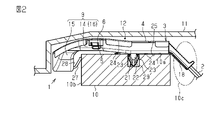
- FIG. 2 is a side view of the protector attached to the vehicle.
- FIG. 3 is an exploded perspective view of the protector.
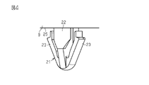
- FIG. 4 is a perspective view of a fixing portion of the protector.
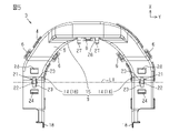
- FIG. 5 is a bottom view of the protector.
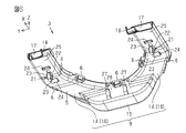
- FIG. 6 is a perspective view of the protector viewed from the bottom side.
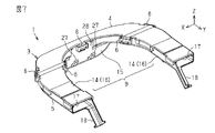
- FIG. 7 is a perspective view of the protector viewed from the top side.
- FIG. 8 is a schematic diagram when a load is applied to the protector.
- FIG. 9(a) is a schematic diagram before the suppressor acts
- FIG. 9(b) is a schematic diagram when the suppressor acts.
- the protector of the present disclosure is a hollow protector body through which electric wires of a wire harness are passed, and at least part of the protector body is arranged in the space between the first article and the second article facing each other.
- a fixing portion configured to fix the protector main body to the first article; and a tilting of the protector main body with the fixing portion as a base point configured to suppress inclination of the protector main body. and a restraining portion.
- the protector when the protector receives a load from above, the protector may tilt with the fixing portion as a base point. Become. For example, there is a possibility that the protector is tilted and a tensile tension acts on the wires at the opening through which the wires of the wire harness are led out from the protector. Therefore, it is possible to protect the wires of the wire harness.
- the protector main body is formed in a shape that crosses the columnar first article. According to this configuration, it is possible to effectively utilize the space around the first article and secure the route for the electric wires of the wire harness.
- a plurality of suppressing portions are provided. According to this configuration, even if the protector tilts with the fixed portion as a base point due to a load applied to the protector from above, the load is dispersed by the plurality of suppressing portions, and the protector is less likely to tilt. It becomes possible.
- the protector main body includes a first wire insertion portion facing the upper surface of the columnar first article, and a second wire insertion portion facing the side surface of the first article.
- the fixing portion is arranged on the bottom surface of the first wire insertion portion.
- the suppressing portion is arranged on the inner surface of the second wire insertion portion.
- the first wire insertion part has a pair of arms arranged in the space.
- the second wire insertion portion is formed in a shape that connects the pair of arm portions.
- the fixing portion is arranged on the arm portion. According to this configuration, even if an obstacle exists at the midpoint of the pair of arm portions, the protector can detour the electric wire and return it to the original wiring route when the detour is not performed.
- the suppressing portion has a distal end and a proximal end, and is configured such that the proximal end of the suppressing portion bends with the distal end of the suppressing portion as a fulcrum. Inclination of the protector main body is suppressed by a reaction force of the bending of the proximal end of the suppressing portion with the distal end serving as a fulcrum.
- the shape of the suppressing portion can be made into a shape in which no member exists at the tip of the suppressing portion. Therefore, it is possible to prevent the leading end of the suppressing portion from interfering with the surrounding wall surface or the like when the suppressing portion is bent.
- the suppressing portion is a spring portion that generates a bending reaction force according to the inclination of the protector body and uses the bending reaction force to suppress the inclination of the protector body. According to this configuration, it is possible to suppress the inclination of the protector body with a simple spring structure.
- the wire harness 1 electrically connects electrical components provided in the vehicle. Examples of electrical equipment include various ECUs, motors, and engines.
- a wire harness 1 includes an electric wire 2 and a protector 3 that covers and protects a part of the electric wire 2. - ⁇ The wire 2 may be a single wire or a bundle of wires.
- the protector 3 is constructed by assembling two housings 4 and 5.
- the two housings 4 , 5 may be an upper housing 4 and a lower housing 5 .
- the two housings 4 , 5 may be assembled and fixed via a plurality of snap fits 6 .
- the internal space of the protector 3 is defined when the two housings 4 and 5 are assembled.
- the electric wire 2 is accommodated in this internal space.
- the protector 3 has a protector main body 9 through which the electric wire 2 is passed. At least part of the protector body 9 is arranged, for example, in the space 12 between the first article 10 and the second article 11 facing each other.
- the first article 10 may be, for example, a cross member extending in the lateral direction of the vehicle body.
- the second article 11 may be, for example, an interior floor (carpet, etc.). Space 12 may be a narrow gap between the cross member and the interior floor.
- the protector body 9 is formed in a shape that traverses the columnar first article 10 .
- the protector body 9 includes a first wire insertion portion 14 arranged on the upper surface 10a of the columnar first article 10 and a second wire insertion portion 15 arranged opposite to the side surface 10b of the first article 10.
- the first wire insertion portion 14 is a pair of arm portions 16 arranged in the space 12 .
- the second wire insertion portion 15 is formed in a shape that connects the pair of arm portions 16 .
- the protector main body 9 is formed in a shape in which a pair of arm portions 16 are connected at their bases, that is, in a so-called U-letter shape.
- An opening 17 for drawing the electric wire 2 into the interior of the protector body 9 is formed at the tip of each arm 16 .
- a guide portion 18 that guides the direction of the wire 2 exposed from the opening 17 is formed in the opening 17 .
- the guide portion 18 may be, for example, a guide piece extending obliquely from the corner of the opening 17 .
- the protector 3 includes a fixing portion 21 configured to fix the protector body 9 to the first article 10 (cross member).
- the fixing portion 21 is arranged on the bottom surface 25 of the first wire insertion portion 14 (for example, the arm portion 16).
- the fixing portion 21 is arranged on each arm portion 16 , and when there are two arm portions 16 , two fixing portions 21 are provided on the protector main body 9 .
- the fixed part 21 has a main body 22 and a projecting piece 23 that engages with the first article 10 (cross member).
- the main body 22 is arranged on the bottom surface 25 of the protector main body 9 (arm portion 16) and is formed, for example, in a rectangular cross section.
- a plurality of projecting pieces 23 are provided.
- the projecting piece 23 has a base connected to the main body 22 and a tip opening toward the bottom surface of the protector main body 9 .
- the pair of fixing parts 21 are arranged on a common transverse line L1 that traverses each arm part 16 and intersects both arm parts 16.
- a pair of push-in pieces 24 are formed on the bottom surface 25 of the protector body 9 (each arm portion 16) so as to sandwich each fixing portion 21 and are spaced apart from each fixing portion 21.
- the pushing piece 24 has, for example, a leaf spring structure. When the protector 3 is attached to the first article 10 , the pushing piece 24 cooperates with the fixing portion 21 to fix the protector 3 to the first article 10 .
- the fixing portion 21 is arranged on the bottom surface 25 of the first wire insertion portion 14 .
- the protector 3 includes a suppressing portion 27 that suppresses inclination of the protector body 9 with the fixed portion 21 as a base point.
- the suppressor 27 may be a plurality of, for example, two suppressors 27 .
- the plurality of suppressing portions 27 are arranged in a row in the width direction of the protector main body 9 (the Y-axis direction in FIG. 6 and the like) at a distance from each other.
- the suppressing portion 27 is arranged on the inner side surface 28 of the second wire insertion portion 15 .
- the suppressing portion 27 may be a spring portion (spring structure) that generates a bending reaction force according to the inclination of the protector body 9 and uses the bending reaction force to suppress the inclination of the protector body 9 .
- the action of the protector 3 of this embodiment will be described.
- the routing route may be restricted due to the presence of an obstacle 10c (see FIG. 2) inside the vehicle.
- a route that bypasses the obstacle 10c must be taken.
- the detour route has to occupy the space 12 between the first article 10 and the second article 11, it is necessary to protect the wire harness 1 from the impact or the like from the second article 11.
- the protector 3 is attached to the first article 10 in the space 12 between the article 10 and the second article 11, and the wire harness 1 is passed through the protector 3.
- the protector 3 is fixed to the first article 10 by attaching the fixing portion 21 formed on the bottom surface of the protector body 9 to the concave portion 29 formed on the upper surface 10a of the first article 10 .
- the recessed portion 29 of the first article 10 may be, for example, an elongated hole in accordance with the shape of the main body 22 of the fixing portion 21 . If the shape combination of the fixing part 21 and the recess 29 is a rectangular cross section and an elongated hole, the fixing part 21 does not rotate in the recess 29 and it is advantageous for firmly fixing the fixing part 21 to the recess 29 .
- the protector 3 when a load is applied to the upper surface of the second article 11, the load is transmitted to the protector 3, and the protector 3 may tilt in the direction of arrow A in the same figure with the fixing portion 21 as a base point.
- the protector 3 tilts with the fixing portion 21 as the base point when the floor is stepped on. If the protector 3 is tilted, the electric wire 2 will be pulled at the opening 17 of the protector 3 and an excessive load will be applied to the wire harness 1 near the opening 17 .
- the bottom surface of the protector body 9 contacts the first article 10, and this contact causes the generation of hammering noise.
- the protector 3 is provided with the suppressing portion 27. Therefore, even if a load that causes the protector 3 to tilt is applied from above the protector 3, the suppressing portion 27 does not move. generates a reaction force according to the inclination of the protector 3.
- the reaction force is advantageous for returning the protector 3 to its original posture (also called initial position). Therefore, even if a load is applied to the protector 3 from above, the protector 3 can be easily held in the initial position, so that the above-described problem can be made less likely to occur.
- the suppressing portion 27 may be a cantilever leaf spring.
- the tip 27a of the restraining portion 27 having a spring structure may be in contact with the side surface 10b of the first article 10 at all times.
- the proximal end 27 b of the suppressing portion 27 may elastically bend with the distal end 27 a of the suppressing portion 27 as a fulcrum to generate a reaction force.
- the tip 27a of the suppressing portion 27 may be tapered and does not need to be bulky. can be done without
- the suppressing portion 27 having a spring structure is advantageous in that it is difficult to prevent load absorption due to elastic deformation of the suppressing portion 27, and it is also advantageous in that a large bending space for the suppressing portion 27 can be secured.
- the suppressing part 27 is a member that is provided in a member (protector 3) that moves to tilt when a load is applied, and suppresses tilting.
- a member protecting 3
- the protector 3 may integrally have the suppressing portion 27 by, for example, integral molding, and may be, for example, a synthetic resin protector.
- the protector 3 includes the protector main body 9 , the fixing portion 21 and the suppressing portion 27 .
- the protector main body 9 is hollow and has an internal space that allows the wires 2 of the wire harness 1 to pass therethrough. At least part of the protector body 9 is arranged in the space 12 between the first article 10 and the second article 11 facing each other.
- the fixing part 21 fixes the protector body 9 to the first article 10 .
- the suppressing portion 27 suppresses inclination of the protector body 9 with the fixing portion 21 as a base point.
- the protector 3 when a load is applied to the protector 3 from above, the protector 3 may tilt with the fixed portion 21 as a base point. It is possible to make it difficult to occur. By the way, if the protector 3 is tilted, the wire 2 may be pulled at the opening 17 of the protector 3 through which the wire 2 is passed, and a load may be applied. situation is unlikely. Therefore, the electric wire 2 can be protected.
- the protector main body 9 is formed in a shape that crosses the columnar first article 10 . According to this configuration, the space around the first article 10 can be effectively used to secure the route for the electric wire 2 .
- a plurality of suppression units 27 are provided. According to this configuration, even if the protector 3 tilts with the fixed portion 21 as the base point due to a load applied to the protector 3 from above, the load is dispersed by the plurality of suppressing portions 27, and the protector 3 does not tilt. can be made difficult.
- the protector body 9 includes a first wire insertion portion 14 facing the upper surface 10a of the columnar first article 10 and a second wire insertion portion 15 facing the side surface 10b of the first article 10.
- the fixing portion 21 is arranged on the bottom surface 25 of the first wire insertion portion 14 .
- the suppressing portion 27 is arranged on the inner side surface 28 of the second wire insertion portion 15 . According to this configuration, even if the protector 3 tilts with the fixing portion 21 as the base point due to the load applied to the protector 3 from above, the suppressing portion 27 that abuts the side surface 10b of the first article 10 firmly prevents the protector 3 from tilting. The position of the protector 3 can be held.
- the first wire insertion portion 14 has a pair of arm portions 16 arranged in the space 12 .
- the second wire insertion portion 15 is formed in a shape that connects the pair of arm portions 16 .
- the fixing portion 21 is arranged on the arm portion 16 . According to this configuration, even if there is an obstacle 10c (see FIG. 2) at the midpoint of the pair of arm portions 16, the protector 3 detours the wire 2, and the wire 2 is detoured on the original routing route when the detour is not performed. can be returned to
- the suppressing portion 27 suppresses inclination of the protector main body 9 by bending the proximal end 27b with the distal end 27a as a fulcrum.
- the shape of the suppressing portion 27 can be a shape in which no member exists at the tip 27 a of the suppressing portion 27 . Therefore, it is possible to prevent the leading end 27a of the suppressing portion 27 from interfering with the surrounding wall surface (for example, the inner surface of the protector 3) when the suppressing portion 27 is bent.
- the suppressing portion 27 is a spring portion that applies a tilt suppressing load to the protector body 9 by a bending reaction force. According to this configuration, the configuration of the suppressing portion 27 can be a simple configuration with a spring structure.
- the first article 10 includes an upper surface 10a, which is an example of a first support surface that supports the protector 1, and an example of a second support surface, which supports the protector 1 and is different from the first support surface. and a corner formed between the top surface 10a and the side surface 10b.
- the first article 10 is an example of a support that supports the protector 1 .
- Arm 16 of protector 3 may be referred to as a hollow arm.
- the second wire insertion portion 15 of the protector 3 may be referred to as an intermediate U-shaped bent portion that hangs down from both arm portions 16 .
- each pushing piece 24 is provided in the protector body 9 so as to form a first buffer space between the bottom surface 25 of the protector body 9 and the top surface 10a of the first article 10, or , provided on the protector body 9 so as to float the bottom surface 25 of the protector body 9 with respect to the top surface 10a of the first article 10, or configured to elastically contact the top surface 10a of the first article 10. Also referred to as an elastically deformable first damper projection.
- each restraining portion 27 is provided in the protector body 9 so as to form a second buffer space between the inner side surface 28 of the protector body 9 and the side surface 10b of the first article 10.
- the inner side surface 28 of the protector body 9 is provided on the protector body 9 so as to float against the side surface 10b of the first article 10, or the side surface 10b of the second article 10 is elastically contacted.
- the fixing part 21 may have a structure in which, for example, a protrusion provided on the first article 10 is inserted into a recess provided on the protector 3 and fixed.
- the fixing part 21 is not limited to an insertion type clip, and may have any shape that can fix the protector 3 to the first article 10 .
- the suppressing portion 27 is not limited to be arranged on the inner side surface 28 of the protector 3, and may be arranged on the bottom surface 25 of the protector main body 9, for example.
- the suppressing portion 27 may be arranged on both the bottom surface 25 and the inner side surface 28 of the protector 3 .
- the arrangement location of the suppressing portion 27 can be freely set as appropriate.
- the suppressing part 27 is not limited to being provided in plurality, and may be, for example, one.
- the suppressing portion 27 is not limited to a spring portion (leaf spring), and may have any shape as long as it can apply a tilting reaction force to the protector 3 .
- the shape of the first wire insertion part 14 and the second wire insertion part 15 is not limited to a flat cross-sectional shape, and may be changed to other shapes such as a circular cross-section or a rectangular cross-section.
- the shape of the protector main body 9 is not limited to the letter U shape. For example, it may be changed to another shape such as an English letter L shape. - The shape of the protector main body 9 is good also as a shape which has only one arm part 16, for example.
- the first article 10 is not limited to a cross member, and may be another member such as a vehicle body frame.
- the second article 11 is not limited to the interior floor of the vehicle, and may be any member that bears the load of the vehicle user, for example.
- the space 12 in which the protector 3 is arranged is not limited to the gap between the first article 10 and the second article 11, and may be any gap that occurs between two members of the vehicle.
- the housing structure of the protector 3 is not limited to the structure in which the two housings 4 and 5 are assembled. For example, it may be composed of three or more housing members, or only one housing member.
- the electric wire 2 is not limited to one electric wire, and may be an electric wire group in which a plurality of electric wires are bundled. Alternatively, the electric wire 2 may be an electric wire whose periphery is covered with a covering material. - Although the present disclosure has been described with reference to examples, it is understood that the present disclosure is not limited to such examples or structures. The present disclosure also includes various modifications and modifications within the equivalent range. In addition, various combinations and configurations, as well as other combinations and configurations, including single elements, more, or less, are within the scope and spirit of this disclosure.
- the present disclosure includes the following embodiments.
- Appendix 1 A hollow first arm through which an electric wire is passed, a hollow second arm arranged to face the first arm and through which the electric wire is passed, the first arm and and a hollow connecting portion formed in a shape for connecting the second arm portions and through which the electric wire is passed.
- the first arm portion and the second arm portion correspond to the first wire insertion portion
- the connecting portion corresponds to the second wire insertion portion.
- the wiring route of the wire harness is subject to space restrictions of the vehicle. For example, a part of the vehicle body or an object mounted on the vehicle may become an obstacle 10c (see FIG. 2) on the routing route of the wire harness. Changing the position of the obstacle 10c requires a major redesign of the vehicle.
- the protector can be positioned such that the protector's first arm, second arm and connecting portion surround or circumvent the obstacle 10c. Therefore, the need for vehicle design changes can be reduced. Alternatively, flexibility in changing the wiring route of the wire harness is improved so that the wiring route of the wire harness can bypass the obstacle 10c.
- Appendix 2 The protector according to Appendix 1, which includes a fixing portion fixed to the article. According to Supplementary Note 2, the protector can be fixed to the article by the fixing portion, so that the protector can be held at a predetermined mounting position.
- the protector In Appendices 1 to 3, the protector extends in a plane intersecting a plane in which the first arm and the second arm extend. According to Supplementary Note 4, the protector can be arranged along the upper surface 10a and the side surface 10b of the article. Therefore, even if the storage space is limited, the protector can be arranged.
- the protector in which the first arm and the second arm are formed to have a rectangular cross section (longitudinal cross section) so that they can be arranged in the gap. With this configuration, the protector can be made thin. Therefore, even if the storage space is limited, the protector can be arranged.
- An embodiment of the present disclosure is a protector (1) used with a support (10) and a wire (2) of a wire harness (1) to protect a length of said wire. and said protector (1) is directed to: a hollow protector body (9) configured to be fixed to the support (10) in an initial position and covering the length of the wire (2) of the wire harness (1); a plurality of elastically deformable first damper projections (24) provided at a plurality of first predetermined positions of the hollow protector body (9); a plurality of elastically deformable second damper projections (27) provided at a plurality of second predetermined positions of the hollow protector body (9),
- the plurality of first damper projections (24) and the plurality of second damper projections (27) when the hollow protector body (9) is tilted from the initial posture with respect to the support (10). may be configured to generate an elastic restoring force that restores the hollow protector body (9) to the initial posture.
- the hollow protector body (9) has two ends (17) having two wire outlets (17) from which the wires (2) are drawn out, and the two ends (17 ) and an intermediate U-bend (15) between said two hollow arms (16) depending from said two hollow arms (16). said intermediate U-bend portion (15);
- the plurality of first damper projections (24) may be integrally formed with the two hollow arms (16) of the hollow protector body (9)
- the plurality of second damper projections (27) may be integrally formed with the intermediate U-shaped bent portion (15) of the hollow protector body (9).
- Each of the plurality of first damper projections (24) is a first leaf spring cantilevered by the two hollow arms (16) of the hollow protector body (9).
- Each of said plurality of second damper projections (27) may be a first leaf spring cantilevered on said intermediate U-shaped bent portion (15) of said hollow protector body (9).
- the support (10) includes a first support surface (10a), a second support surface (10b) different from the first support surface (10a), and the first support surface (10a). and a corner between the second support surface (10b), Said plurality of first damper projections (24) elastically contact said first support surface (10a) of said support (10), said hollow protector body (9) and said first support surface (10a) 10a) may be configured to form a first buffer space between The plurality of second damper projections (27) are in elastic contact with the second support surface (10b) of the support (10), the hollow protector body (9) and the second support surface (10b) 10b) to form a second buffer space.
Landscapes
- Engineering & Computer Science (AREA)
- Architecture (AREA)
- Civil Engineering (AREA)
- Structural Engineering (AREA)
- Mechanical Engineering (AREA)
- Details Of Indoor Wiring (AREA)
Abstract
Description
[1]本開示のプロテクタは、ワイヤハーネスの電線が通される中空のプロテクタ本体であって、当該プロテクタ本体の少なくとも一部は、対向する第1物品及び第2物品の間の空間に配置されるように構成される前記プロテクタ本体と、前記プロテクタ本体を前記第1物品に固定するように構成される固定部と、前記固定部を基点とした前記プロテクタ本体の傾きを抑制するように構成される抑制部とを備えている。
本開示のプロテクタの具体例を、以下に図面を参照しつつ説明する。なお、本発明はこれらの例示に限定されるものではなく、特許請求の範囲によって示され、特許請求の範囲と均等の意味および範囲内でのすべての変更が含まれることが意図される。各図面では、説明の便宜上、構成の一部を誇張又は簡略化して示す場合がある。また、各部分の寸法比率についても、実際とは異なる場合がある。
図2に示す通り、ワイヤハーネス1は、例えば、第1物品10に沿って配策される場合、車内の障害物10c(図2参照)の存在によって配策経路が制限されることがある。この場合、障害物10cを迂回する経路をとらなければならない。このとき、迂回経路が第1物品10及び第2物品11の間の空間12をとらざるを得ない場合、第2物品11からの衝撃等からワイヤハーネス1を保護する必要があるため、第1物品10及び第2物品11の空間12において第1物品10にプロテクタ3を取り付け、このプロテクタ3にワイヤハーネス1を通すことで対処する。
(1)プロテクタ3は、プロテクタ本体9、固定部21、及び、抑制部27を備えている。プロテクタ本体9は、中空であり、ワイヤハーネス1の電線2の挿通を許容する内部空間を有する。プロテクタ本体9の少なくとも一部は、対向する第1物品10及び第2物品11の間の空間12に配置される。固定部21は、プロテクタ本体9を第1物品10に固定する。抑制部27は、固定部21を基点としたプロテクタ本体9の傾きを抑制する。
・固定部21は、例えば、第1物品10に設けられた突起を、プロテクタ3に設けられた凹部に挿し込んで固定する構造でもよい。
・抑制部27は、プロテクタ3の内側面28に配置されることに限らず、例えば、プロテクタ本体9の底面25に配置されてもよい。
・抑制部27の配置場所は、適宜自由に設定できる。
・抑制部27は、複数設けられることに限らず、例えば1つとしてもよい。
・第1電線挿通部14及び第2電線挿通部15の形状は、断面扁平形状に限らず、例えば、断面円状や断面四角形状などの他の形状に変更してもよい。
・プロテクタ本体9の形状は、例えば、腕部16を1つのみ有する形状としてもよい。
・第2物品11は、車内床面に限定されず、例えば、車両利用者の荷重がかかる部材であればよい。
・プロテクタ3のハウジング構造は、2つのハウジング4、5を組み付ける構造に限定されない。例えば、3つ以上のハウジング部材から構成されてもよいし、ハウジング部材を1つのみとしてもよい。
・本開示は、実施例に準拠して記述されたが、本開示は当該実施例や構造に限定されるものではないと理解される。本開示は、様々な変形例や均等範囲内の変形をも包含する。加えて、様々な組み合わせや形態、さらには、それらに一要素のみ、それ以上、あるいはそれ以下、を含む他の組み合わせや形態をも、本開示の範疇や思想範囲に入るものである。
(付記1)電線が通される中空の第1腕部と、前記第1腕部と対向するように配置され、前記電線が通される中空の第2腕部と、前記第1腕部及び前記第2腕部を連結する形状に形成され、前記電線が通される中空の連結部とを備えるプロテクタ。
ワイヤハーネスの配策経路は車両のスペース制約を受ける。例えば、車体の一部または車両搭載物がワイヤハーネスの配策経路上の障害物10c(図2参照)になることがある。障害物10cの位置変更は、車両の大掛かりな設計変更を必要とする。本開示によれば、プロテクタの第1腕部、第2腕部及び連結部が障害物10cを囲むようにまたは迂回するようにプロテクタを配置することができる。したがって、車両の設計変更の必要性を低減できる。または、ワイヤハーネスの配索経路が障害物10cを迂回できるように、ワイヤハーネスの配索経路の変更の柔軟性が向上する。
前記支持体(10)に初期姿勢で固定されるように構成され、前記ワイヤハーネス(1)の前記電線(2)の前記ある長さ部分を覆う中空のプロテクタ本体(9)と、
前記中空のプロテクタ本体(9)の第1の複数の所定位置に設けられた弾性変形可能な複数の第1のダンパ突起(24)と、
前記中空のプロテクタ本体(9)の第2の複数の所定位置に設けられた弾性変形可能な複数の第2のダンパ突起(27)とを備えることができ、
前記中空のプロテクタ本体(9)が前記支持体(10)に対して前記初期姿勢から傾斜したときに、前記複数の第1のダンパ突起(24)及び前記複数の第2のダンパ突起(27)は前記中空のプロテクタ本体(9)を前記初期姿勢に復帰させる弾性復元力を生成するように構成されてよい。
前記複数の第1のダンパ突起(24)は、前記中空のプロテクタ本体(9)の前記2つの中空腕部(16)に一体形成されてよく、
前記複数の第2のダンパ突起(27)は、前記中空のプロテクタ本体(9)の前記中間U字曲げ部分(15)に一体形成されてよい。
前記複数の第2のダンパ突起(27)の各々は、前記中空のプロテクタ本体(9)の前記中間U字曲げ部分(15)に片持ち支持された第1の板バネであってよい。
前記複数の第1のダンパ突起(24)は、前記支持体(10)の前記第1支持面(10a)に弾性的に接触し、前記中空のプロテクタ本体(9)と前記第1支持面(10a)との間に第1のバッファ空間を形成するように構成されてよく、
前記複数の第2のダンパ突起(27)は、前記支持体(10)の前記第2支持面(10b)に弾性的に接触し、前記中空のプロテクタ本体(9)と前記第2支持面(10b)との間に第2のバッファ空間を形成するように構成されてよい。
2 電線
3 プロテクタ
4 ハウジング
5 ハウジング
6 スナップフィット部
9 プロテクタ本体
10 第1物品
11 第2物品
12 空間
10a 第1物品の上面
10b 第1物品の側面
14 第1電線挿通部
15 第2電線挿通部
16 腕部
17 開口部
18 ガイド部
21 固定部
22 本体
23 突片
24 押込片(第1のダンパ突起)
25 底面
27 抑制部(ばね部、第2のダンパ突起)
28 内側面
29 凹部
L1 横断線
Claims (11)
- ワイヤハーネスの電線が通される中空のプロテクタ本体であって、当該プロテクタ本体の少なくとも一部は、対向する第1物品及び第2物品の間の空間に配置されるように構成される前記プロテクタ本体と、
前記プロテクタ本体を前記第1物品に固定するように構成される固定部と、
前記固定部を基点とした前記プロテクタ本体の傾きを抑制するように構成される抑制部と
を備えるプロテクタ。 - 前記プロテクタ本体は、柱状の前記第1物品を横断する形状に形成されている
請求項1に記載のプロテクタ。 - 前記抑制部は、複数設けられている
請求項1又は請求項2に記載のプロテクタ。 - 前記プロテクタ本体は、柱状の前記第1物品の上面に対向配置される第1電線挿通部と、前記第1物品の側面に対向配置される第2電線挿通部とを備え、
前記固定部は、前記第1電線挿通部の底面に配置され、
前記抑制部は、前記第2電線挿通部の内側面に配置されている
請求項1から請求項3のいずれか一項に記載のプロテクタ。 - 前記第1電線挿通部は、前記空間に配置される一対の腕部を備え、
前記第2電線挿通部は、一対の前記腕部を連結する形状に形成され、
前記固定部は、各腕部に配置されている
請求項4に記載のプロテクタ。 - 前記抑制部は、先端と基端とを有し、前記抑制部の前記先端を支点として前記抑制部の前記基端が撓むように構成されており、前記抑制部は、前記抑制部の前記先端を支点とする前記抑制部の前記基端の撓みの反力によって前記プロテクタ本体の傾きを抑制する
請求項1から請求項5のいずれか一項に記載のプロテクタ。 - 前記抑制部は、前記プロテクタ本体の傾きに応じて曲げ反力を生成し、前記曲げ反力を利用して前記プロテクタ本体の傾きを抑制するばね部である
請求項1から請求項6のいずれか一項に記載のプロテクタ。 - 支持体、及び、ワイヤハーネスの電線とともに用いられ、前記電線のある長さ部分を保護するプロテクタであって、
前記支持体に初期姿勢で固定されるように構成され、前記ワイヤハーネスの前記電線の前記ある長さ部分を覆う中空のプロテクタ本体と、
前記中空のプロテクタ本体の第1の複数の所定位置に設けられた弾性変形可能な複数の第1のダンパ突起と、
前記中空のプロテクタ本体の第2の複数の所定位置に設けられた弾性変形可能な複数の第2のダンパ突起とを備え、
前記中空のプロテクタ本体が前記支持体に対して前記初期姿勢から傾斜したときに、前記複数の第1のダンパ突起及び前記複数の第2のダンパ突起は前記中空のプロテクタ本体を前記初期姿勢に復帰させる弾性復元力を生成するように構成される、プロテクタ。 - 前記中空のプロテクタ本体は、前記電線がそこから引き出される2つの電線引き出し口を有する2つの端部と、前記2つの端部からそれぞれ延びる2つの中空腕部と、前記2つの中空腕部の間の中間U字曲げ部分であって、前記2つの中空腕部から垂れ下がった前記中間U字曲げ部分とを含み、
前記複数の第1のダンパ突起は、前記中空のプロテクタ本体の前記2つの中空腕部に一体形成されており、
前記複数の第2のダンパ突起は、前記中空のプロテクタ本体の前記中間U字曲げ部分に一体形成されている、
請求項8に記載のプロテクタ。 - 前記複数の第1のダンパ突起の各々は、前記中空のプロテクタ本体の前記2つの中空腕部に片持ち支持された第1の板バネであり、
前記複数の第2のダンパ突起の各々は、前記中空のプロテクタ本体の前記中間U字曲げ部分に片持ち支持された第1の板バネである
請求項9に記載のプロテクタ。 - 前記支持体は、第1支持面と、前記第1支持面とは異なる第2支持面と、前記第1支持面と前記第2支持面との間の角部とを有し、
前記複数の第1のダンパ突起は、前記支持体の前記第1支持面に弾性的に接触し、前記中空のプロテクタ本体と前記第1支持面との間に第1のバッファ空間を形成するように構成され、
前記複数の第2のダンパ突起は、前記支持体の前記第2支持面に弾性的に接触し、前記中空のプロテクタ本体と前記第2支持面との間に第2のバッファ空間を形成するように構成される、
請求項8から10のいずれか一項に記載のプロテクタ。
Priority Applications (2)
| Application Number | Priority Date | Filing Date | Title |
|---|---|---|---|
| CN202280013306.3A CN116806401A (zh) | 2021-03-11 | 2022-02-21 | 保护器 |
| US18/280,639 US20240140333A1 (en) | 2021-03-11 | 2022-02-21 | Protector |
Applications Claiming Priority (2)
| Application Number | Priority Date | Filing Date | Title |
|---|---|---|---|
| JP2021039080A JP7615782B2 (ja) | 2021-03-11 | 2021-03-11 | プロテクタ |
| JP2021-039080 | 2021-03-11 |
Publications (1)
| Publication Number | Publication Date |
|---|---|
| WO2022190843A1 true WO2022190843A1 (ja) | 2022-09-15 |
Family
ID=83227762
Family Applications (1)
| Application Number | Title | Priority Date | Filing Date |
|---|---|---|---|
| PCT/JP2022/007036 Ceased WO2022190843A1 (ja) | 2021-03-11 | 2022-02-21 | プロテクタ |
Country Status (4)
| Country | Link |
|---|---|
| US (1) | US20240140333A1 (ja) |
| JP (1) | JP7615782B2 (ja) |
| CN (1) | CN116806401A (ja) |
| WO (1) | WO2022190843A1 (ja) |
Families Citing this family (1)
| Publication number | Priority date | Publication date | Assignee | Title |
|---|---|---|---|---|
| US12459450B2 (en) * | 2022-12-01 | 2025-11-04 | Nissan North America, Inc. | Wiring protector assembly |
Citations (3)
| Publication number | Priority date | Publication date | Assignee | Title |
|---|---|---|---|---|
| JPS63103078U (ja) * | 1986-12-24 | 1988-07-04 | ||
| JP2013169803A (ja) * | 2012-02-17 | 2013-09-02 | Sumitomo Wiring Syst Ltd | 電装部品のガタツキ防止構造 |
| JP2019205222A (ja) * | 2018-05-21 | 2019-11-28 | 矢崎総業株式会社 | プロテクタ及びプロテクタの取付構造 |
Family Cites Families (4)
| Publication number | Priority date | Publication date | Assignee | Title |
|---|---|---|---|---|
| JP2964445B2 (ja) * | 1994-11-08 | 1999-10-18 | 矢崎総業株式会社 | ハーネスプロテクタ |
| US6567602B2 (en) * | 2001-07-11 | 2003-05-20 | Siemens Information And Communication Networks, Inc. | Fiber-optic cable trough, low-profile PCB mount |
| EP1363375B1 (en) * | 2002-05-14 | 2010-11-17 | Yazaki Corporation | Wire harness protector |
| US7887012B2 (en) * | 2009-03-31 | 2011-02-15 | Denso International America, Inc. | Insert for tube retaining bracket |
-
2021
- 2021-03-11 JP JP2021039080A patent/JP7615782B2/ja active Active
-
2022
- 2022-02-21 WO PCT/JP2022/007036 patent/WO2022190843A1/ja not_active Ceased
- 2022-02-21 CN CN202280013306.3A patent/CN116806401A/zh active Pending
- 2022-02-21 US US18/280,639 patent/US20240140333A1/en active Pending
Patent Citations (3)
| Publication number | Priority date | Publication date | Assignee | Title |
|---|---|---|---|---|
| JPS63103078U (ja) * | 1986-12-24 | 1988-07-04 | ||
| JP2013169803A (ja) * | 2012-02-17 | 2013-09-02 | Sumitomo Wiring Syst Ltd | 電装部品のガタツキ防止構造 |
| JP2019205222A (ja) * | 2018-05-21 | 2019-11-28 | 矢崎総業株式会社 | プロテクタ及びプロテクタの取付構造 |
Also Published As
| Publication number | Publication date |
|---|---|
| JP7615782B2 (ja) | 2025-01-17 |
| CN116806401A (zh) | 2023-09-26 |
| US20240140333A1 (en) | 2024-05-02 |
| JP2022138924A (ja) | 2022-09-26 |
Similar Documents
| Publication | Publication Date | Title |
|---|---|---|
| JP6564813B2 (ja) | 電線の保護ケース | |
| CN112582949B (zh) | 夹持件及线束 | |
| WO2022190843A1 (ja) | プロテクタ | |
| KR200496491Y1 (ko) | 차량용 내비게이션 장착을 위한 결합 구조 | |
| JP6323368B2 (ja) | 電線配索構造 | |
| CN115117802B (zh) | 保护器以及车辆的布线结构 | |
| JP7605031B2 (ja) | ワイヤハーネス及びワイヤハーネスシステム | |
| JPH0965542A (ja) | プロテクタ | |
| US20240116467A1 (en) | Electrical connection box | |
| JP2008293859A (ja) | プロテクタ付きコネクタ | |
| JP5030660B2 (ja) | プロテクタ付きコネクタ | |
| JP6584379B2 (ja) | 車載用給電装置 | |
| JP7639048B2 (ja) | 電線の保護構造 | |
| JP2025038388A (ja) | 固定構造、及び、ワイヤハーネス | |
| JP7803741B2 (ja) | 外装部材、及び、ワイヤハーネス | |
| JP4653967B2 (ja) | ワイヤハーネスの保持構造及び該保持構造を備えた電気接続箱 | |
| JP6831757B2 (ja) | プロテクタ | |
| KR20240042930A (ko) | 커넥터 고정클립 | |
| JP2021093859A (ja) | ワイヤハーネス用のプロテクタ、及び、ワイヤハーネス | |
| JP2023007791A (ja) | 筐体 | |
| JP2024120460A (ja) | 装着部材、装着部材付きコルゲートチューブ及びコルゲート付きワイヤーハーネス | |
| JP2023093515A (ja) | プロテクタ及びワイヤハーネス | |
| JP2025058557A (ja) | コネクタユニット | |
| JP2024147295A (ja) | 端子台およびワイヤハーネス | |
| JP2023007145A (ja) | プロテクタ |
Legal Events
| Date | Code | Title | Description |
|---|---|---|---|
| 121 | Ep: the epo has been informed by wipo that ep was designated in this application |
Ref document number: 22766806 Country of ref document: EP Kind code of ref document: A1 |
|
| WWE | Wipo information: entry into national phase |
Ref document number: 202280013306.3 Country of ref document: CN |
|
| WWE | Wipo information: entry into national phase |
Ref document number: 18280639 Country of ref document: US |
|
| NENP | Non-entry into the national phase |
Ref country code: DE |
|
| 122 | Ep: pct application non-entry in european phase |
Ref document number: 22766806 Country of ref document: EP Kind code of ref document: A1 |