WO2022190474A1 - シート、シートクッション、シートシステム、および車両システム - Google Patents
シート、シートクッション、シートシステム、および車両システム Download PDFInfo
- Publication number
- WO2022190474A1 WO2022190474A1 PCT/JP2021/043322 JP2021043322W WO2022190474A1 WO 2022190474 A1 WO2022190474 A1 WO 2022190474A1 JP 2021043322 W JP2021043322 W JP 2021043322W WO 2022190474 A1 WO2022190474 A1 WO 2022190474A1
- Authority
- WO
- WIPO (PCT)
- Prior art keywords
- seat
- cushion
- backrest
- sheet
- obstacle
- Prior art date
- Legal status (The legal status is an assumption and is not a legal conclusion. Google has not performed a legal analysis and makes no representation as to the accuracy of the status listed.)
- Ceased
Links
Images




















Classifications
-
- B—PERFORMING OPERATIONS; TRANSPORTING
- B60—VEHICLES IN GENERAL
- B60N—SEATS SPECIALLY ADAPTED FOR VEHICLES; VEHICLE PASSENGER ACCOMMODATION NOT OTHERWISE PROVIDED FOR
- B60N2/00—Seats specially adapted for vehicles; Arrangement or mounting of seats in vehicles
- B60N2/002—Seats provided with an occupancy detection means mounted therein or thereon
- B60N2/0021—Seats provided with an occupancy detection means mounted therein or thereon characterised by the type of sensor or measurement
- B60N2/003—Seats provided with an occupancy detection means mounted therein or thereon characterised by the type of sensor or measurement characterised by the sensor mounting location in or on the seat
- B60N2/0034—Seats provided with an occupancy detection means mounted therein or thereon characterised by the type of sensor or measurement characterised by the sensor mounting location in or on the seat in, under or on the seat cover
-
- A—HUMAN NECESSITIES
- A47—FURNITURE; DOMESTIC ARTICLES OR APPLIANCES; COFFEE MILLS; SPICE MILLS; SUCTION CLEANERS IN GENERAL
- A47C—CHAIRS; SOFAS; BEDS
- A47C7/00—Parts, details, or accessories of chairs or stools
- A47C7/54—Supports for the arms
-
- A—HUMAN NECESSITIES
- A47—FURNITURE; DOMESTIC ARTICLES OR APPLIANCES; COFFEE MILLS; SPICE MILLS; SUCTION CLEANERS IN GENERAL
- A47C—CHAIRS; SOFAS; BEDS
- A47C7/00—Parts, details, or accessories of chairs or stools
- A47C7/62—Accessories for chairs
- A47C7/72—Adaptations for incorporating lamps, radio sets, bars, telephones, ventilation, heating or cooling arrangements or the like
- A47C7/74—Adaptations for incorporating lamps, radio sets, bars, telephones, ventilation, heating or cooling arrangements or the like for ventilation, heating or cooling
-
- B—PERFORMING OPERATIONS; TRANSPORTING
- B60—VEHICLES IN GENERAL
- B60K—ARRANGEMENT OR MOUNTING OF PROPULSION UNITS OR OF TRANSMISSIONS IN VEHICLES; ARRANGEMENT OR MOUNTING OF PLURAL DIVERSE PRIME-MOVERS IN VEHICLES; AUXILIARY DRIVES FOR VEHICLES; INSTRUMENTATION OR DASHBOARDS FOR VEHICLES; ARRANGEMENTS IN CONNECTION WITH COOLING, AIR INTAKE, GAS EXHAUST OR FUEL SUPPLY OF PROPULSION UNITS IN VEHICLES
- B60K26/00—Arrangement or mounting of propulsion-unit control devices in vehicles
- B60K26/02—Arrangement or mounting of propulsion-unit control devices in vehicles of initiating means or elements
-
- B—PERFORMING OPERATIONS; TRANSPORTING
- B60—VEHICLES IN GENERAL
- B60N—SEATS SPECIALLY ADAPTED FOR VEHICLES; VEHICLE PASSENGER ACCOMMODATION NOT OTHERWISE PROVIDED FOR
- B60N2/00—Seats specially adapted for vehicles; Arrangement or mounting of seats in vehicles
- B60N2/02—Seats specially adapted for vehicles; Arrangement or mounting of seats in vehicles the seat or part thereof being movable, e.g. adjustable
- B60N2/04—Seats specially adapted for vehicles; Arrangement or mounting of seats in vehicles the seat or part thereof being movable, e.g. adjustable the whole seat being movable
- B60N2/12—Seats specially adapted for vehicles; Arrangement or mounting of seats in vehicles the seat or part thereof being movable, e.g. adjustable the whole seat being movable slidable and tiltable
-
- B—PERFORMING OPERATIONS; TRANSPORTING
- B60—VEHICLES IN GENERAL
- B60N—SEATS SPECIALLY ADAPTED FOR VEHICLES; VEHICLE PASSENGER ACCOMMODATION NOT OTHERWISE PROVIDED FOR
- B60N2/00—Seats specially adapted for vehicles; Arrangement or mounting of seats in vehicles
- B60N2/02—Seats specially adapted for vehicles; Arrangement or mounting of seats in vehicles the seat or part thereof being movable, e.g. adjustable
- B60N2/04—Seats specially adapted for vehicles; Arrangement or mounting of seats in vehicles the seat or part thereof being movable, e.g. adjustable the whole seat being movable
- B60N2/14—Seats specially adapted for vehicles; Arrangement or mounting of seats in vehicles the seat or part thereof being movable, e.g. adjustable the whole seat being movable rotatable, e.g. to permit easy access
-
- B—PERFORMING OPERATIONS; TRANSPORTING
- B60—VEHICLES IN GENERAL
- B60N—SEATS SPECIALLY ADAPTED FOR VEHICLES; VEHICLE PASSENGER ACCOMMODATION NOT OTHERWISE PROVIDED FOR
- B60N2/00—Seats specially adapted for vehicles; Arrangement or mounting of seats in vehicles
- B60N2/56—Heating or ventilating devices
-
- B—PERFORMING OPERATIONS; TRANSPORTING
- B60—VEHICLES IN GENERAL
- B60N—SEATS SPECIALLY ADAPTED FOR VEHICLES; VEHICLE PASSENGER ACCOMMODATION NOT OTHERWISE PROVIDED FOR
- B60N2/00—Seats specially adapted for vehicles; Arrangement or mounting of seats in vehicles
- B60N2/75—Arm-rests
- B60N2/787—Arm-rests detachable
-
- B—PERFORMING OPERATIONS; TRANSPORTING
- B60—VEHICLES IN GENERAL
- B60N—SEATS SPECIALLY ADAPTED FOR VEHICLES; VEHICLE PASSENGER ACCOMMODATION NOT OTHERWISE PROVIDED FOR
- B60N2/00—Seats specially adapted for vehicles; Arrangement or mounting of seats in vehicles
- B60N2/80—Head-rests
- B60N2/882—Head-rests detachable
-
- B—PERFORMING OPERATIONS; TRANSPORTING
- B60—VEHICLES IN GENERAL
- B60N—SEATS SPECIALLY ADAPTED FOR VEHICLES; VEHICLE PASSENGER ACCOMMODATION NOT OTHERWISE PROVIDED FOR
- B60N2/00—Seats specially adapted for vehicles; Arrangement or mounting of seats in vehicles
- B60N2/90—Details or parts not otherwise provided for
-
- B—PERFORMING OPERATIONS; TRANSPORTING
- B60—VEHICLES IN GENERAL
- B60W—CONJOINT CONTROL OF VEHICLE SUB-UNITS OF DIFFERENT TYPE OR DIFFERENT FUNCTION; CONTROL SYSTEMS SPECIALLY ADAPTED FOR HYBRID VEHICLES; ROAD VEHICLE DRIVE CONTROL SYSTEMS FOR PURPOSES NOT RELATED TO THE CONTROL OF A PARTICULAR SUB-UNIT
- B60W60/00—Drive control systems specially adapted for autonomous road vehicles
-
- G—PHYSICS
- G05—CONTROLLING; REGULATING
- G05G—CONTROL DEVICES OR SYSTEMS INSOFAR AS CHARACTERISED BY MECHANICAL FEATURES ONLY
- G05G1/00—Controlling members, e.g. knobs or handles; Assemblies or arrangements thereof; Indicating position of controlling members
- G05G1/30—Controlling members actuated by foot
- G05G1/40—Controlling members actuated by foot adjustable
-
- B—PERFORMING OPERATIONS; TRANSPORTING
- B60—VEHICLES IN GENERAL
- B60N—SEATS SPECIALLY ADAPTED FOR VEHICLES; VEHICLE PASSENGER ACCOMMODATION NOT OTHERWISE PROVIDED FOR
- B60N2/00—Seats specially adapted for vehicles; Arrangement or mounting of seats in vehicles
- B60N2/02—Seats specially adapted for vehicles; Arrangement or mounting of seats in vehicles the seat or part thereof being movable, e.g. adjustable
- B60N2/04—Seats specially adapted for vehicles; Arrangement or mounting of seats in vehicles the seat or part thereof being movable, e.g. adjustable the whole seat being movable
- B60N2/06—Seats specially adapted for vehicles; Arrangement or mounting of seats in vehicles the seat or part thereof being movable, e.g. adjustable the whole seat being movable slidable
-
- B—PERFORMING OPERATIONS; TRANSPORTING
- B60—VEHICLES IN GENERAL
- B60N—SEATS SPECIALLY ADAPTED FOR VEHICLES; VEHICLE PASSENGER ACCOMMODATION NOT OTHERWISE PROVIDED FOR
- B60N2/00—Seats specially adapted for vehicles; Arrangement or mounting of seats in vehicles
- B60N2/02—Seats specially adapted for vehicles; Arrangement or mounting of seats in vehicles the seat or part thereof being movable, e.g. adjustable
- B60N2/22—Seats specially adapted for vehicles; Arrangement or mounting of seats in vehicles the seat or part thereof being movable, e.g. adjustable the back-rest being adjustable
-
- B—PERFORMING OPERATIONS; TRANSPORTING
- B60—VEHICLES IN GENERAL
- B60N—SEATS SPECIALLY ADAPTED FOR VEHICLES; VEHICLE PASSENGER ACCOMMODATION NOT OTHERWISE PROVIDED FOR
- B60N2/00—Seats specially adapted for vehicles; Arrangement or mounting of seats in vehicles
- B60N2/24—Seats specially adapted for vehicles; Arrangement or mounting of seats in vehicles for particular purposes or particular vehicles
- B60N2/30—Non-dismountable or dismountable seats storable in a non-use position, e.g. foldable spare seats
-
- B—PERFORMING OPERATIONS; TRANSPORTING
- B60—VEHICLES IN GENERAL
- B60N—SEATS SPECIALLY ADAPTED FOR VEHICLES; VEHICLE PASSENGER ACCOMMODATION NOT OTHERWISE PROVIDED FOR
- B60N2/00—Seats specially adapted for vehicles; Arrangement or mounting of seats in vehicles
- B60N2/70—Upholstery springs ; Upholstery
- B60N2/7094—Upholstery springs
-
- B—PERFORMING OPERATIONS; TRANSPORTING
- B60—VEHICLES IN GENERAL
- B60N—SEATS SPECIALLY ADAPTED FOR VEHICLES; VEHICLE PASSENGER ACCOMMODATION NOT OTHERWISE PROVIDED FOR
- B60N2/00—Seats specially adapted for vehicles; Arrangement or mounting of seats in vehicles
- B60N2/75—Arm-rests
-
- B—PERFORMING OPERATIONS; TRANSPORTING
- B60—VEHICLES IN GENERAL
- B60N—SEATS SPECIALLY ADAPTED FOR VEHICLES; VEHICLE PASSENGER ACCOMMODATION NOT OTHERWISE PROVIDED FOR
- B60N2/00—Seats specially adapted for vehicles; Arrangement or mounting of seats in vehicles
- B60N2/80—Head-rests
- B60N2/806—Head-rests movable or adjustable
- B60N2/838—Tiltable
- B60N2/856—Tiltable movable to an inoperative or stowed position
Definitions
- the present disclosure relates to seats, seat cushions, seat systems, and vehicle systems.
- the applicant is considering using a pressure sensor provided on the seat to detect the movement of a person sitting on the seat and applying it to various things. Even in such a seat, it can be expected that the movement of the seated person will generate electricity.
- the power generation device is provided under the cushion pad as in the prior art, there is a problem that the vibration is not efficiently transmitted to the power generation device and power cannot be generated efficiently. It is desired to provide a seat and seat cushion that can efficiently generate electricity from the movement of the occupant.
- a new seat includes a seat frame, a pad body covering the seat frame, and a power generation device that generates power by vibration.
- the power generation device is placed on the seated person side of the pad body.
- the power generation device that generates power by vibration is arranged on the seated person side of the pad body, so when the seated person moves, the vibration is efficiently transmitted to the power generation device. Therefore, it is possible to efficiently generate power by the movement of the seated person.
- the seat described above can further include a skin member covering the pad body.
- the power generation device can be positioned between the pad body and the skin member.
- the pad body has a recess on the surface facing the seated person, and that the power generation device be positioned in the recess.
- the sheet further includes a cover pad that covers the power generation device.
- the seat can further comprise a pressure sensor arranged on the occupant's side of the pad body.
- the power generation device may be connected to power the pressure sensor.
- the pressure sensor may be arranged on the occupant's side of the power generation device, overlapping the power generation device.
- a seat cushion that is used by being arranged on the seating surface of the seat.
- the seat cushion includes a pad body and a power generation device arranged on the side of the seated person of the pad body and generating power by vibration.
- the power generation device that generates power by vibration is arranged on the seated person side of the pad body, so when the seated person moves, the vibration is efficiently transmitted to the power generation device. Therefore, it is possible to efficiently generate power by the movement of the seated person.
- the seat cushion can further include a skin member covering the pad body.
- the power generation device can be positioned between the pad body and the skin member.
- the pad body has a recess on the surface facing the seated person, and that the power generation device be positioned in the recess.
- the seat cushion further include a cover pad that covers the power generation device.
- the seat cushion can further include a pressure sensor arranged on the side of the seated person of the pad body.
- the power generation device may be connected to power the pressure sensor.
- the pressure sensor may overlap the power generation device and be arranged on the side of the seated person of the power generation device.
- the seat and seat cushion described above it is possible to efficiently generate power by the movement of the seated person. In addition, it is possible to improve the sitting comfort of the seat and the seat cushion provided with the power generation device capable of efficiently generating power. In addition, by arranging the pressure sensor so as to overlap the power generation device on the side of the seated person, it is easy to connect the pressure sensor and the power generation device, and the sensitivity of the pressure sensor is not impaired.
- the target to which the power generation device supplies power is not limited to the pressure sensor.
- the power generating device can be connected to various electrical devices provided inside and outside the seat, such as other types of sensors, blowers, motors, heaters, lighting, etc., to supply power.
- power can also be supplied by the power generation device described above.
- a seat that includes a seat body having a seat portion, a backrest, and a headrest, and a cartridge detachable from the seat body.
- the headrest includes a blower port for blowing out air, an air intake port for sucking in air, a cartridge mounting portion to which the cartridge is detachably mounted, and the cartridge mounting portion inside the headrest from the air intake port.
- a fan for forming an airflow therethrough toward the air outlet.
- the cartridge is attached to the cartridge attachment portion so that an air current passing through the cartridge attachment portion can pass through the cartridge attachment portion. are placed.
- the cartridge mounting portion is arranged in the portion of the headrest located behind the head of the seated person, so that the cartridge can be easily replaced.
- At least one of the seat, backrest and headrest is provided with a power generation device and connected to the fan to supply power to the fan.
- the cartridge may be configured to be mountable from behind or above the cartridge mounting portion.
- the headrest may have a plurality of the cartridge mounting portions.
- the cartridge mounting portion has an opening for mounting the cartridge
- the headrest includes a cover movable between an open position in which the opening is opened and a closed position in which the opening is closed. It can be configured to have.
- the opening of the cartridge mounting portion can be closed by the cover when the device is used without mounting the cartridge.
- the headrest may have a biasing member that biases the cover toward the closed position.
- the opening of the cartridge mounting portion can be automatically closed by the cover when the cartridge is removed. As a result, it is possible to prevent forgetting to close the cover.
- the cartridge mounting portion may have a claw portion for holding the cartridge with the cartridge mounted thereon.
- the cartridge has a ventilation part that communicates the inside and the outside of the cartridge, and has a ventilation part that can pass an air flow passing through the cartridge mounting part in a state of being mounted in the cartridge mounting part. can be configured.
- the cartridge mounting portion may have a shutter for opening and closing the ventilation portion.
- the airflow passing through the cartridge mounting portion can be switched between a state in which the airflow passes through the ventilation portion of the cartridge and a state in which it does not pass through the ventilation portion, so that the functions of the cartridge can be used. You can switch on or off. Further, in a configuration having a plurality of cartridge mounting portions, the cartridge to be used can be switched by switching the open/closed state of the shutter for each cartridge mounting portion.
- the headrest may have a first duct that communicates between the intake port and the cartridge mounting portion, and a second duct that communicates between the cartridge mounting portion and the blower port.
- the cartridge may have at least one of an aroma source, a temperature adjuster, an ion generator and an air purifier.
- an obstacle detection sensor for detecting an obstacle in the trajectory of the seat until the seat is switched from the normal state to the storage state; and the state of the seat is changed from the normal state to the stored state.
- a sheet system is disclosed that is capable of executing sheet storage processing for changing to the storage state, and that includes a control unit that determines whether or not to execute the sheet storage processing.
- control unit determines to execute the sheet storage process based on the information from the recognition unit, before starting the sheet storage process, based on the information from the obstacle detection sensor It is determined whether or not there is an obstacle in the trajectory, and if it is determined that there is no obstacle, the sheet storage process is started, and if it is determined that there is an obstacle, the sheet storage process is started. not start.
- the sheet storage process before starting the sheet storage process, it is determined whether or not there is an obstacle in the trajectory based on the information from the obstacle detection sensor, and if it is determined that there is an obstacle, Since the sheet storage process is not started, it is possible to prevent obstacles from restricting the movement of the sheet that is operated by the execution of the sheet storage process. Further, by providing a power generation device on the seat and connecting it to the obstacle detection sensor, power can be supplied to the obstacle detection sensor.
- the obstacle detection sensor may detect the presence or absence of an object on the seating surface of the seat.
- the obstacle detection sensor can also be used as a seat belt reminder sensor that detects whether or not an occupant is sitting on the seat, for example, so that costs can be reduced.
- the seat may include a seat and a backrest rotatable with respect to the seat, and the backrest may be folded so as to face the seat in the stored state.
- the backrest in the stowed state, the backrest is folded so as to face the seat portion, so that the stowage space in the passenger compartment can be made larger than in the normal state.
- the seat may be arranged in front of a luggage compartment located in the rear portion of the vehicle, and in the stowed state, the seat may be arranged in front of the normal state.
- the controller determines that there is an obstacle and decides not to start the seat storage process, the controller notifies the occupant of non-execution information indicating that the seat storage process will not be performed. good too.
- an occupant outside the vehicle can know that the seat is not in the stowed state based on the notification of the non-execution information before opening the vehicle door. Before opening it, you can drop the items you have on the ground. Therefore, it is possible to eliminate the need for the occupant to carry out unreasonable actions such as holding luggage with one hand and opening the vehicle door with the other hand, expecting that the seat is in the stowed state.
- control unit may notify the non-execution information by a portable terminal that the passenger can carry.
- the non-execution information is notified by the mobile terminal carried by the passenger, it is easier for the crew to confirm the non-execution information compared to the case where the non-execution information is notified by the internal speaker of the vehicle, for example.
- the controller determines that there is no obstacle and decides to start the seat storage process, the controller notifies the occupant of execution information indicating that the seat storage process will be executed. good too.
- an occupant outside the vehicle can know that the seat is in the stowed state based on the notification of the execution information before opening the door of the vehicle. You can safely open the vehicle door while holding it.
- control unit may notify the execution information by a portable terminal that the passenger can carry.
- a seat mounted in a vehicle capable of switching between automatic operation and non-automatic operation comprising a seat portion and a backrest rotatable with respect to the seat portion, in which an occupant sits.
- a seat that can switch between a possible normal state and a relaxed state in which the backrest is tilted backward from the normal state, and an obstacle in the trajectory of the seat from the normal state to the relaxed state is detected.
- a seat system capable of executing a reclining process for changing the state of the seat from the normal state to the relaxed state, and a control unit that determines whether or not to execute the reclining process. do.
- the controller determines to execute the reclining process by switching from the non-automatic driving to the automatic driving or at the request of an occupant, before starting the reclining process, the obstacle Based on the information from the detection sensor, it is determined whether or not there is an obstacle in the trajectory. When it is determined that there is no obstacle, the reclining process is started. does not start the reclining process.
- the process before starting the reclining process, it is determined whether or not there is an obstacle in the trajectory based on the information from the obstacle detection sensor. Since the process is not started, it is possible to suppress the movement of the seat that is operated by the execution of the reclining process from being restricted by the obstacle. Further, by providing a power generation device on the seat and connecting it to the obstacle detection sensor, power can be supplied to the obstacle detection sensor.
- the seat system may further include a rear seat arranged behind the seat, and the obstacle detection sensor may detect the presence or absence of an object on the seating surface of the rear seat.
- the obstacle detection sensor can be used, for example, as a seat belt reminder sensor that detects whether or not an occupant is seated in the rear seat, so costs can be reduced.
- the seat may be arranged behind the normal state.
- the space in front of the seat can be made larger than in the normal state, so the occupant can be more relaxed.
- the controller may notify the occupant of non-execution information indicating that the reclining process will not be executed. .
- the occupant can know that the reclining process will not be executed.
- control unit may notify the non-execution information by a portable terminal that the passenger can carry.
- the non-execution information is notified by the mobile terminal carried by the passenger, compared with the case where the non-execution information is notified by the internal speaker of the vehicle, for example, the music played by the internal speaker of the vehicle is temporarily stopped. control is not required.
- control part may inform the occupant of execution information indicating that the reclining process will be executed.
- the occupant can know that the reclining process will be executed.
- control unit may notify the execution information by a portable terminal that the passenger can carry.
- the execution information is notified by the portable terminal carried by the passenger, for example, compared with the case where the execution information is notified by the internal speaker of the vehicle, the control such as temporarily stopping the music played by the internal speaker of the vehicle is performed. no need to do
- a pedal for operating a vehicle the pedal being movable between an operating position operable by a passenger and a retracted position farther from the passenger than the operating position; an obstacle detection sensor that detects an obstacle in the trajectory of the pedal until it switches from the position to the retracted position; and a pedal retraction process that changes the position of the pedal from the operation position to the retracted position.
- a control unit that determines whether or not to execute the pedal retraction process. When it is decided to execute the pedal retraction process, the control unit determines whether there is an obstacle within the trajectory based on information from the obstacle detection sensor before starting the pedal retraction process. If it is determined that there is no obstacle, the pedal retraction process is started, and if it is determined that there is an obstacle, the pedal retraction process is not started.
- the pedal storage process before starting the pedal storage process, it is determined whether or not there is an obstacle in the trajectory based on the information from the obstacle detection sensor, and if it is determined that there is an obstacle, Since the pedal retraction process is not started, it is possible to prevent obstacles from restricting the movement of the pedals operated by executing the pedal retraction process. Further, by providing a power generation device on a seat mounted in a vehicle and connecting it to an obstacle detection sensor, power can be supplied to the obstacle detection sensor.
- the vehicle is a vehicle capable of switching between automatic driving and non-automatic driving, and the control unit executes the pedal retraction process on condition that the non-automatic driving is switched to the automatic driving. may decide.
- the vehicle system further includes a seat arranged behind the pedals, and the control unit determines to execute the pedal retraction process on condition that an application program using the seat as a controller is activated. You may
- control unit may prohibit execution of the application program when determining that there is the obstacle and not starting the pedal retraction process.
- the execution of the application program is prohibited when the pedal retraction process is not started. Therefore, the application program is executed while the pedals are in the operating position, and the pedals do not interfere with the movement of the occupant. can be suppressed.
- the controller determines that there is an obstacle and decides not to start the pedal retraction process, the controller notifies the occupant of non-execution information indicating that the pedal retraction process will not be executed. good too.
- the occupant can know that the pedal retraction process will not be executed.
- control unit may notify the non-execution information by a portable terminal that the passenger can carry.
- the non-execution information is notified by the mobile terminal carried by the passenger, compared with the case where the non-execution information is notified by the internal speaker of the vehicle, for example, the music played by the internal speaker of the vehicle is temporarily stopped. control is not required.
- the controller determines that there is no obstacle and decides to start the pedal retraction process, the controller notifies the occupant of execution information indicating that the pedal retraction process will be executed. good too.
- the occupant can know that the pedal retraction process will be executed.
- control unit may notify the execution information by a portable terminal that the passenger can carry.
- the execution information is notified by the portable terminal carried by the passenger, for example, compared with the case where the execution information is notified by the internal speaker of the vehicle, the control such as temporarily stopping the music played by the internal speaker of the vehicle is performed. no need to do
- a seat that is rotatable about an axis along the vertical direction and is rotatable between a first orientation and a second orientation that is different from the first orientation a sheet; an obstacle detection sensor that detects an obstacle in a trajectory of the sheet until the sheet is switched from the first orientation to the second orientation;
- a seat system capable of executing a sheet orientation change process to change the orientation of the sheet to , and comprising a control unit that determines whether or not to execute the sheet orientation change process.
- the control section determines whether an obstacle exists within the trajectory based on information from the obstacle detection sensor before starting the sheet orientation change process. If it is determined that there is no obstacle, the sheet orientation changing process is started, and if it is determined that there is an obstacle, the sheet orientation changing process is not started.
- the sheet orientation changing process before starting the sheet orientation changing process, it is determined whether or not there is an obstacle in the trajectory based on the information from the obstacle detection sensor, and if it is determined that there is an obstacle, Since the sheet orientation changing process is not started, it is possible to prevent the movement of the sheet moving due to the execution of the sheet orientation changing process from being restricted by an obstacle. Further, by providing a power generation device on the seat and connecting it to the obstacle detection sensor, power can be supplied to the obstacle detection sensor.
- control unit can determine whether or not a state in which the passengers can easily communicate with each other should be established. It may decide to take action.
- the seat may be mounted in a vehicle capable of automatically driving, and the control unit may determine to execute the seat orientation change process based on a request from a passenger during automatic driving.
- the controller determines that there is an obstacle and decides not to start the seat orientation change process, the controller notifies the occupant of non-execution information indicating that the seat orientation change process will not be executed. You may
- the occupant can know that the seat orientation change process will not be executed.
- control unit may notify the non-execution information by a portable terminal that the passenger can carry.
- the non-execution information is notified by the mobile terminal carried by the passenger, compared with the case where the non-execution information is notified by the internal speaker of the vehicle, for example, the music played by the internal speaker of the vehicle is temporarily stopped. control is not required.
- the controller determines that there is no obstacle and decides to start the seat orientation change process, the controller notifies the occupant of execution information indicating that the seat orientation change process is to be executed. You may
- the occupant can know that the seat orientation change process will be executed.
- control unit may notify the execution information by a portable terminal that the passenger can carry.
- the execution information is notified by the portable terminal carried by the passenger, for example, compared with the case where the execution information is notified by the internal speaker of the vehicle, the control such as temporarily stopping the music played by the internal speaker of the vehicle is performed. no need to do
- a base portion having a seat cushion, a backrest cushion, a lower support portion that supports the seat cushion from below, and a rear support portion that supports the backrest cushion from behind, and a blower. , and an operating portion for a seated person to operate the blower.
- the seat cushion is removable from the lower support and the back cushion is removable from the rear support.
- At least one of the seat cushion and the backrest cushion has a cushion air passage through which the airflow generated by the blower passes, and has a ventilation opening that opens toward the seated person, and the operation is performed as described above.
- a portion is provided on the left or right side of the base portion, or on the side located on at least one of the left and right of the seat cushion and protruding above the seat cushion.
- the ventilation opening may be provided at a position spaced at a predetermined distance or more to the left or right from the left-right center of the seat cushion or the backrest cushion.
- the ventilation openings can be provided at positions left and right away from the left and right centers of the seat cushion and the backrest cushion, so it is possible to prevent the ventilation openings from being blocked by the seated person.
- the air can be well blown out or drawn in from the seat cushion and the backrest cushion, so that the comfort of the seated person can be enhanced.
- the base portion has the side portion, and the side portion is a side ventilation passage through which an air flow formed by the blower passes, the side ventilation passage opening toward the seated person. It can be configured to have a path.
- air can be blown out or sucked in from the sides. This can further enhance the comfort of the seated person.
- the blower may be arranged inside the base portion.
- the base portion has a first base portion ventilation path that communicates the blower and the cushion ventilation path, and one of the first base portion ventilation path and the cushion ventilation path is provided at an end.
- a tubular portion is provided, and the cushion air passage and the first base air passage are connected by the tubular portion entering the other of the first base air passage and the cushion air passage. can do.
- the base portion has a first base portion ventilation passage that communicates the blower and the cushion ventilation passage, and the first base portion ventilation passage opens toward the cushion ventilation passage.
- the cushion air passage has a second opening that opens toward the first base air passage, and the cushion air passage and the first base air passage are connected to the first opening. It can be set as the structure which communicates by the said 2nd opening facing each other.
- the base portion is a second base portion ventilation passage that communicates the outside of the base portion with the blower, and the second base portion ventilation passage opens rearward at a lower portion of the base portion.
- the opening of the second base air passage opening to the outside can be arranged at an inconspicuous position on the seat.
- the seat may include an electric wire for supplying electric power to the blower, the base portion may have the side portion, and the electric wire may be drawn rearward from the side portion. .
- the seat may be provided with an electric wire for supplying power to the blower, and the electric wire may be drawn rearward from the left-right central portion of the base portion.
- the blower is provided so as to blow air toward the seated person from the ventilation opening, and the seat has a position in which air is blown out toward the seated person and a direction in which air is blown out toward the seated person.
- the operation section may be configured to be able to operate the change mechanism.
- the seated person can change the position and the direction of air blowing according to the preference of the seated person by operating the operation unit, so that the comfortable feeling of the seated person can be further enhanced. can be done.
- the operation portion may be an operation switch for operating the change mechanism, and may be configured to have an operation switch composed of four switches arranged in a cross shape.
- the base portion may have the side portion, the side portion may be an armrest, and the operation portion may be provided on the upper surface of the armrest.
- a seat body having a seat on which a person sits and a backrest, a side portion positioned at least one of the left and right of the seat and projecting above the seat, and a seat-shaped A seat
- the heater includes at least one of a seat heater that heats a surface of the seat that faces the occupant and a backrest heater that heats a surface of the backrest that faces the occupant, and the side portions of the heater that face the occupant. and a side heater for heating the surface to be coated.
- the surface of the seat facing the occupant can be warmed by the seat heater
- the surface of the backrest facing the occupant can be warmed by the backrest heater
- the side part can be warmed by the side heater.
- power can be supplied to the heater.
- the side portion may be an armrest
- the side portion heater may include an armrest heater for heating the upper surface of the armrest
- the upper surface of the armrest can be warmed by the armrest heater. This can enhance the comfort of the seated person.
- the side heaters may include inner surface heaters for heating left and right inner surfaces of the side portions.
- the inner surface heater can heat the left and right inner surfaces of the side portions, so that the seated person can be warmed from the sides. This can enhance the comfort of the seated person.
- the side portion may be detachable from the seat body.
- the seat portion has a seat cushion and a lower support portion that supports the seat cushion from below, and the seat cushion is detachable from the lower support portion.
- the backrest may have a backrest cushion and a rear support portion that supports the backrest cushion from behind, and the backrest cushion may be detachable from the rear support portion. can.
- the seat may further include a headrest, and the heater may include a headrest heater that heats a surface of the headrest facing the occupant.
- the headrest heater can heat the surface of the headrest facing the seated person. This can enhance the comfort of the seated person.
- the seat includes an electric wire for supplying electric power to the heater, the seat has a seat cushion, and a lower support portion that supports the seat cushion from below, and the electric wire is connected to the heater.
- the seat cushion may be pulled out rearward from the seat body at a position below the lower end of the seat cushion.
- At least one of the seat heater and the backrest heater has a heater wire and a sheet-like base material for supporting the heater wire, and the base material has a plurality of cuts. can do.
- the heater when a person sits on the seat or leans against the backrest, the heater is appropriately deformed, so that the seated person does not feel uncomfortable.
- the cuts may extend in the front-rear direction or the up-down direction, and the plurality of cuts may be arranged side by side.
- a seat that includes a seat body having a seat portion and a backrest on which a person sits, a headrest, and a sheet-like heater.
- the heater faces at least one of a seat heater that heats a surface of the seat that faces the occupant and a backrest heater that heats a surface of the backrest that faces the occupant, and the headrest faces the occupant.
- a headrest heater for heating the surface.
- the surface of the seat facing the occupant can be warmed by the seat heater
- the surface of the backrest facing the occupant can be warmed by the backrest heater
- the headrest can be seated by the headrest heater.
- the surface facing the person can be warmed. This can enhance the comfort of the seated person.
- a power generation device in at least one of the seat portion, backrest and headrest of the seat and connecting it to the heater, power can be supplied to the heater.
- the seat portion has a seat cushion and a lower support portion that supports the seat cushion from below, and the seat cushion is detachable from the lower support portion.
- the backrest may have a backrest cushion and a rear support portion that supports the backrest cushion from behind, and the backrest cushion may be detachable from the rear support portion. can.
- the seat includes an electric wire for supplying electric power to the heater, the seat has a seat cushion, and a lower support portion that supports the seat cushion from below, and the electric wire is connected to the heater.
- the seat cushion may be pulled out rearward from the seat body at a position below the lower end of the seat cushion.
- At least one of the seat heater and the backrest heater has a heater wire and a sheet-like base material for supporting the heater wire, and the base material has a plurality of cuts. can do.
- the heater when a person sits on the seat or leans against the backrest, the heater is appropriately deformed, so that the seated person does not feel uncomfortable.
- the cuts may extend in the front-rear direction or the up-down direction, and the plurality of cuts may be arranged side by side.
- the seat further includes a side portion positioned on at least one of the left side and the right side of the seat portion and protruding above the seat portion, and the heater heats a surface of the side portion facing the occupant. It can be configured to include side heaters that
- the side heater can heat the side facing the seated person. This can enhance the comfort of the seated person.
- the side portion may be an armrest
- the side portion heater may include an armrest heater for heating the upper surface of the armrest
- the upper surface of the armrest can be warmed by the armrest heater. This can enhance the comfort of the seated person.
- the side heaters may include inner surface heaters for heating left and right inner surfaces of the side portions.
- the inner surface heater can heat the left and right inner surfaces of the side portions, so that the seated person can be warmed from the sides. This can enhance the comfort of the seated person.
- the side portion may be detachable from the seat body.
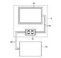
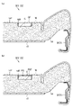
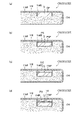
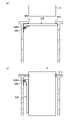
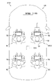
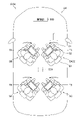
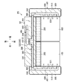
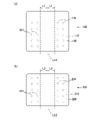
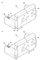
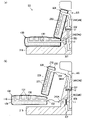
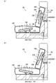
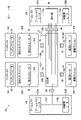
- FIG. 4 is a diagram showing connections between a power generation device and a pressure sensor; (a) A cross-sectional view of a portion of the sheet where the power generation device is arranged, and (b) a cross-sectional view of the portion of the sheet where the power generation device and the pressure sensor are arranged.
- FIG. 4A is a cross-sectional view of a portion of the sheet where the power generating device is arranged, and (b) is a cross-sectional view of the portion of the sheet where the power generating device and the pressure sensor are arranged, when a cover pad is provided.
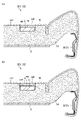
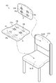
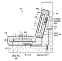
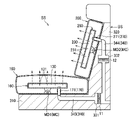
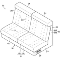
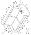
- FIG. 5 is a perspective view showing a seat cushion according to a second embodiment; (a) a cross-sectional view of the sheet where the power generation device is arranged, (b) a cross-sectional view of the seat where the power generation device and the pressure sensor are arranged, and (c) the power generation device when the cover pad is provided.
- FIG. 10A is a cross-sectional view of the seat where the power generation device and the pressure sensor are placed when (d) a cover pad is provided;
- FIG. FIG. 11 is a perspective view of a seat according to a third embodiment; It is a perspective view which shows the structure of a headrest. It is a sectional view showing composition of a headrest.
- FIG. 10A is a cross-sectional view of the seat where the power generation device and the pressure sensor are placed when (d) a cover pad is provided.
- FIG. 11 is a perspective view of a seat according to a third embodiment; It is a perspective view which shows the structure of a headrest. It is
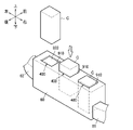
- FIG. 11 is a perspective view showing a cartridge mounting portion of a third embodiment
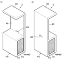
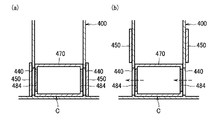
- 3A and 3B are cross-sectional views of the cartridge mounting portion, showing a state in which the cartridge is mounted, FIG. ) and (d) showing the XX section of (a).
- 4A and 4B are perspective views of a cartridge
- FIG. 4A to 4D are sectional views showing specific examples of the configuration of the cartridge
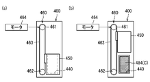
- FIG. FIG. 4 is a diagram for explaining the shutter, and FIG. 4A shows a state in which the shutter is in a fully closed position, and FIG. 4B shows a state in which the shutter is in a fully open position. It is the figure (a), (b) which shows an example of a shutter drive mechanism.
- 4 is a control block diagram of the seat; FIG. FIG.
- FIG. 11 is a perspective view showing a cartridge mounting portion of a fourth embodiment; It is sectional drawing of the cartridge mounting part of 4th Embodiment.
- 13A to 13C are diagrams showing modifications of the shutter;
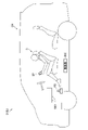
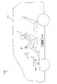
- FIG. FIG. 11 is a diagram showing a seat system according to a fifth embodiment;
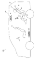
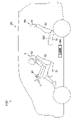
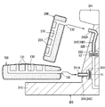
- FIG. FIG. 10 is a diagram showing a state in which the seat is switched from the normal state to the stored state;
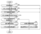
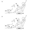
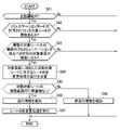
- 4 is a flow chart showing the operation of a control unit; 4A to 4C show specific examples of the operation of the control unit;
- FIG. FIG. 11 is a diagram showing a seat system according to a sixth embodiment;
- FIG. 10 is a diagram showing a state in which the seat is switched from the normal state to the relaxed state; 4 is a flow chart showing the operation of a control unit; It is a figure (a) and (b) which show the example of operation
- FIG. 12 is a diagram showing a seat system according to an eighth embodiment; FIG. FIG.
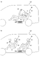
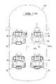
- FIG. 10 is a diagram illustrating a state in which the sheet is switched from the first orientation to the second orientation; 4 is a flow chart showing the operation of a control unit; FIG. 10 is a diagram showing a specific example of the operation of the control unit, in which the front passenger seat and the two seats in the second row are target seats, and the two seats in the second row are rotation target seats.
- FIG. 10 is a diagram illustrating a state in which sheet orientation change processing has been performed;
- FIG. 10 is a diagram showing a state in which sheet orientation change processing has not been executed due to the presence of an obstacle;
- FIG. 21 is a perspective view showing a sofa as an example of a seat according to a ninth embodiment; It is an exploded perspective view of a sofa.
- FIG. 10 is a diagram illustrating a state in which the sheet is switched from the first orientation to the second orientation
- 4 is a flow chart showing the operation of a control unit
- FIG. 10 is a diagram showing a specific example of the operation of the control unit,
- FIG. 4 is a cross-sectional view showing a cushion airway and a configuration related to the cushion airway;
- FIG. 4 is a cross-sectional view showing a side air passage and a configuration related to the side air passage; It is the front view (a) of a seat part cushion, and the front view (b) of a backrest cushion.
- FIG. 22 is a cross-sectional view for explaining the connection between the cushion airway and the first base airway in the ninth embodiment;
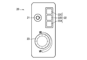
- FIG. 21 is a diagram showing an operation unit according to a ninth embodiment; It is the perspective view (a) which shows the structure with which the electric wire was pulled out from the armrest, and the perspective view (b) which shows the structure with which the electric wire was pulled out from the left-right central part of the base part.
- FIG. 10A and 10B are sectional views for explaining the connection between the cushion airway and the first base airway in the tenth embodiment;
- FIG. FIG. 21 is a cross-sectional view showing a sofa of an eleventh embodiment; It is a figure which shows the operation part of 11th Embodiment. It is sectional drawing (a), (b) which shows operation
- FIG. 21 is a sectional view showing a sofa of a twelfth embodiment; It is sectional drawing (a), (b) which shows operation
- FIG. 11 is a perspective view showing a sofa of a first modified example; FIG.
- FIG. 11 is a perspective view showing a sofa of a second modified example
- FIG. 21 is a perspective view showing a sofa as an example of a seat according to a thirteenth embodiment; It is an exploded perspective view of a sofa. It is sectional drawing of a sofa. It is the front view (a) of a seat part heater, and the front view (b) of a backrest heater.
- Fig. 2 is a front view of the sofa showing a cross-section of the armrest; It is a figure which shows an operation part. It is a figure for demonstrating the connection of a heater and an operation part. It is the perspective view which looked at the sofa from the back.
- FIG. 32 is a perspective view showing a sofa according to a modified example of the thirteenth embodiment;
- the seat S of the present embodiment is connected to, for example, a smartphone SP, and is used as a seat experience device for operating an application of the smartphone SP by a seated person moving on the seat S.
- the seat S may be installed in the vehicle, or may be installed in a facility other than the vehicle.
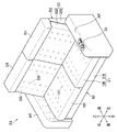
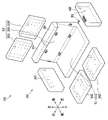
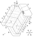
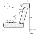
- the seat S includes a seat portion S1, a backrest S2, and a headrest S3. Specifically, the seat S includes a seat frame F as shown in FIG. 2, a pad body 14 covering the seat frame F as shown in FIGS. 18.
- the seat frame F has a seat portion frame F1 that forms the frame of the seat portion S1 and a backrest frame F2 that forms the frame of the backrest S2.
- the frame of the headrest S3 is detachably attached to the backrest frame F2 at the upper end of the backrest frame F2.
- the frame of the headrest S3 is also covered with a pad and an upholstery member.
- the seat frame F1 and the backrest frame F2 include left and right side frames SF that are spaced apart from each other in the left and right direction, and support members 15 that are arranged between the left and right side frames SF and receive the load from the seated person. have The support member 15 supports the central portion of the pad main body 14 in the left-right direction, as shown in FIGS.
- the seat portion S1 includes a front surface S11 facing forward, a central surface S12 positioned at the center in the left-right direction of the upper surface on which a seated person sits, and an overhanging surface S13 overhanging above the surface S12.
- the backrest S2 has a central surface S22 located in the center in the left-right direction, which is a surface that supports the seated person from behind, and overhanging surfaces S23 located on both left and right sides of the central surface S22 and projecting forward from the central surface S22. and
- front and rear, left and right, and up and down are based on the seated person sitting on the seat S.
- the seat S is provided with a plurality of pressure sensors PS (PS1 to PS6) on the seat portion S1 and the backrest S2.
- the pressure sensor PS is arranged on the seated person side of the pad main body 14, specifically, between the pad main body 14 and the skin member 18 (see FIG. 4(b)).
- the pressure sensor PS is, for example, an element whose resistance value changes due to external pressure.
- the pressure sensor PS is arranged so as to be able to detect the state of the seat surface facing the user sitting on the seat S, and detects the pressure exerted by the user sitting on the seat S on the seat surface.
- Each pair of pressure sensors PS1 to PS6 is provided symmetrically with respect to the center of the left and right sides of the seat S.
- the seat portion S1 is provided with pressure sensors PS1 to PS3.
- the pressure sensor PS1 is provided at the front part in front of the center of the seat part S1 in the front-rear direction, and is arranged so as to be able to measure the pressure from the thighs of the seated person.
- the pressure sensor PS2 and the pressure sensor PS3 are for measuring the pressure from the user's buttocks. Since both the pressure sensor PS2 and the pressure sensor PS3 are for measuring the pressure from the user's buttocks, only one of them may be provided. Pressure sensor PS2 and pressure sensor PS3 are positioned behind the center of the seat surface of seat portion S1 in the front-rear direction.
- the pressure sensor PS2 and the pressure sensor PS3 are arranged at a large rearward distance from the pressure sensor PS1. Specifically, the pressure sensor PS3 is provided at a position corresponding to the bottom of the user's sit bones. In this position, the user's load is greatest. The pressure sensor PS2 is arranged slightly before the pressure sensor PS3.
- Pressure sensors PS4 to PS6 are provided on the backrest S2.
- the pressure sensor PS4 is provided at a position corresponding to the back of the user's waist.
- Pressure sensor PS5 is positioned slightly above pressure sensor PS4. Both the pressure sensor PS4 and the pressure sensor PS5 are for measuring the pressure from the waist of the user, and only one of them may be provided.
- the pressure sensor PS6 is arranged at a large distance above the pressure sensors PS4 and PS5.
- a pressure sensor PS6 is positioned corresponding to the user's shoulder and is capable of measuring the pressure from the user's shoulder.
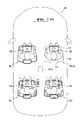
- the seat is provided with a plurality of power generation devices G (31-34, 41-46) on the seat portion S1 and the backrest S2.
- Each power generation device G is arranged on the seated person side of the pad body 14, specifically, between the pad body 14 and the skin member 18 (see FIGS. 4A and 4B).
- the power generation device G is a device that generates power by vibration.
- a pair of power generation devices 31 are arranged on the front surface S11 of the seat portion S1 so as to be spaced apart from each other in the left and right direction.
- a pair of power generation devices 32 are arranged on the front end portion of the center surface S12 of the seat portion S1 so as to be spaced apart from each other in the left and right direction.
- a pair of power generation devices 33 are arranged at a position overlapping the pressure sensor PS2 on the center surface S12 of the seat portion S1, and are spaced apart from each other to the left and right.
- the power generation devices 34 are arranged on the left and right projecting surfaces S13 of the seat portion S1. Each power generation device 34 is positioned substantially in the center in the front-rear direction.
- the power generation devices 41, 42, 43, 44 are arranged in this order from bottom to top in the left and right center portions of the center surface S22 of the backrest S2.
- the power generation device 41 is positioned below the center of the backrest S2 in the vertical direction, corresponding to the waist height of the seated person.
- the power generation device 42 is positioned substantially in the center of the backrest S2, corresponding to the center of the seated person's back.
- the power generation devices 43 and 44 are positioned above the center of the backrest S2 in the vertical direction, corresponding to the shoulder height of the seated person.
- a pair of power generation devices 45 are arranged on the center surface S22 of the backrest S2 so as to be spaced apart from each other in the left and right direction.
- the power generation device 45 is provided corresponding to the height of the center of the seated person's back.
- the power generation devices 46 are arranged on the left and right projecting surfaces S23 of the backrest S2. Each power generation device 46 is positioned substantially in the center in the vertical direction.
- the power generation device G includes a power generation element PE, a control unit 30, and a wiring W1 connecting the power generation element PE and the control unit 30.
- the control unit 30 is connected to the pressure sensor PS by wiring W2 so as to supply the power generated by the power generation device G to the pressure sensor PS, and detects the pressure applied to the pressure sensor PS.
- the power generation element PE is composed of a piezoelectric element or the like.
- the power generation element PE is formed in a size and shape that can efficiently generate power at the frequency of vibration caused by the motion of the seated person.
- the control unit 30 includes a capacitor that stores electricity generated by the power generation element PE, a circuit that detects the resistance of the pressure sensor PS, and a communication device that wirelessly transmits the detected pressure to an external device such as a smartphone SP. there is The power generation element PE also supplies the generated power to the communication device.
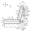
- the pad main body 14 has a recess 14R on the surface 14F facing the seated person.
- the power generation device G is positioned inside the recess 14R.
- the surface GF of the power generation device G on the side of the seated person is flush with the surface 14F of the pad body 14 on the side of the seated person.
- the pressure sensor PS and the power generation device G are arranged to overlap like the pressure sensor PS2 and the power generation device 33 shown in FIG. It overlaps and is arrange
- the seated person side surface PSF of the pressure sensor PS is flush with the seated person side surface 14F of the pad body 14 .
- the smartphone SP receives the measured pressure value from the control unit 30 of the power generation device G.
- An application is installed on the smartphone SP, and a game or the like using this pressure value is provided.
- the content of the application is not particularly limited, for example, when a seated person sits on the seat S and raises and lowers his legs, it is possible to provide a game in which a character runs according to the number of up-and-down movements and competes.
- the power generation device G that generates power by vibration is arranged on the seated person side of the pad body 14, the power generation device G vibrates when the seated person moves. Communicate efficiently. Therefore, it is possible to efficiently generate power by the movement of the seated person.
- the power generation device G is positioned in the recess 14R of the pad main body 14, the seated person hardly feels the power generation device G as a foreign object, and the sitting comfort can be improved.
- the pressure sensor PS overlaps the power generation device G, it is easy to connect the pressure sensor PS and the power generation device G. Further, since the power generation device G is arranged on the side of the seated person, the sensitivity of the pressure sensor PS is not impaired.
- the seat S may further include a cover pad 16, as shown in FIGS. 5(a) and 5(b), in order to further improve sitting comfort.
- the cover pad 16 is arranged to overlap the power generation device G on the side of the seated person.
- the recess 14R is formed with a depth that is the sum of the thickness of the power generation device G and the thickness of the cover pad 16, and the surface 16F of the cover pad 16 on the seated person side is flush with the surface 14F of the pad body 14 on the seated person side.
- the cover pad 16 is arranged to overlap the pressure sensor PS on the seated person side.
- the concave portion 14R is formed with a depth that is the sum of the thickness of the power generation device G, the thickness of the pressure sensor PS, and the thickness of the cover pad 16. It is flush with the surface 14F on the user side.
- the cover pad 16 is arranged on the seated person side of the power generation device G, so that the seated person is less likely to feel the power generation device G as a foreign object, and is comfortable to sit on. can be further improved.
- the seat cushion CS is placed on the seating surface of the seat S10 and used.
- the seat S10 has a seat portion S110 and a backrest S120.
- the seat cushion CS has a seat portion cushion CS1 arranged on the seating surface of the seat portion S110 and a backrest cushion CS2 arranged on the seating surface of the backrest S120.
- the seat cushion CS1 and the backrest cushion CS2 are constructed independently.
- a plurality of pressure sensors PS and a plurality of power generating devices G are arranged on the seat cushion CS1 and the backrest cushion CS2, as in the first embodiment. Some of the power generation devices G are arranged so as to overlap the pressure sensor PS, and other power generation devices G are arranged without overlapping the pressure sensor PS.
- the seat cushion CS (CS1, CS2) includes a pad body 114 and a skin member 118 covering the pad body 114.
- the power generation device G is arranged on the seated person side of the pad main body 114 , specifically between the pad main body 114 and the skin member 118 .
- the pad main body 114 has a recessed portion 114R on a surface 114F facing the seated person.
- the power generation device G is positioned inside the recess 114R.
- the surface GF of the power generation device G on the side of the seated person is flush with the surface 114F of the pad body 114 on the side of the seated person.
- the pressure sensor PS overlaps the power generation device G and is arranged on the seated person side of the power generation device G, as shown in FIG. 7(b).
- the seated person side surface PSF of the pressure sensor PS is flush with the seated person side surface 114F of the pad main body 114 .
- the power generation device G that generates power by vibration is arranged on the seated person side of the pad body 114, the power generation device G vibrates when the seated person moves. is transmitted efficiently. Therefore, it is possible to efficiently generate power by the movement of the seated person.
- the power generation device G is positioned in the recess 114R of the pad main body 114, the seated person hardly feels the power generation device G as a foreign object, and the sitting comfort can be improved.
- the pressure sensor PS overlaps the power generation device G, it is easy to connect the pressure sensor PS and the power generation device G. Further, since the power generation device G is arranged on the side of the seated person, the sensitivity of the pressure sensor PS is not impaired.
- the power generation device G supplies power to the communication device, it is possible to transmit the detected pressure from the seat cushion CS provided with the pressure sensor PS to the smartphone SP without the need for a power supply.
- the experience system can be used in places where there is no power supply.
- the seat S may further include a cover pad 116, as shown in FIGS. 7(c) and 7(d), in order to further improve sitting comfort.
- the cover pad 116 is arranged to overlap the power generation device G on the side of the seated person.
- the recess 114R is formed with a depth that is the sum of the thickness of the power generation device G and the thickness of the cover pad 116, and the surface 116F of the cover pad 116 on the side of the seated person is flush with the surface 114F of the pad main body 114 on the side of the seated person.
- the cover pad 116 is arranged to overlap the pressure sensor PS on the seated person side.
- the concave portion 114R is formed with a depth that is the sum of the thickness of the power generation device G, the thickness of the pressure sensor PS, and the thickness of the cover pad 116. It is flush with the surface 114F on the user side.
- the cover pad 116 is arranged on the seated person's side of the power generation device G, thereby making it difficult for the seated person to feel the power generation device G as a foreign object, thereby improving the sitting comfort. can be further improved.
- the seat according to the first embodiment and the seat cushion according to the second embodiment have been described above, the above-described embodiments can be modified as appropriate.
- the power generation device G was positioned in the recesses 14R, 114R of the pad bodies 14, 114, but the recesses 14R, 114R were formed in the pad bodies 14, 114.
- the power generation device G may be arranged on the surfaces 14F, 114F of the pad bodies 14, 114 facing the seated person.
- both the seat portion S1 and the backrest S2 are provided with the power generation device G, but the power generation device G may be provided only in the seat portion S1 or only in the backrest S2. good too.
- the headrest S3 is not provided with the power generation device G, the headrest S3 may be provided with the power generation device G.
- the power generation device G may be provided on at least one of the seat portion S1, the backrest S2, and the headrest S3.
- both the seat cushion CS1 and the backrest cushion CS2 are provided with the power generation device G, but the power generation device may be provided only in the seat cushion CS1 and the backrest cushion. It may be provided only in CS2.
- the seat S and the seat cushion CS described above are provided with the skin members 18 and 118, they may not be provided with the skin members.
- the seat cushion CS1 and the backrest cushion CS2 are independently configured in the above-described seat cushion CS, the seat cushion CS1 and the backrest cushion CS2 may be connected.
- another member may be sandwiched between the power generation device G and the pressure sensor PS.
- the power generation device G supplies power to the pressure sensor PS, but it may also supply power to something other than the pressure sensor.
- Power generation devices may, for example, power heaters, lights, blowers, motors, and the like.
- a third embodiment and a fourth embodiment relating to a seat having a seat portion, a backrest and a headrest and provided with a detachable cartridge will be described.
- a conventionally known seat includes a seat body having a seat portion, a backrest, and a headrest, and an air freshener detachable from the headrest of the seat body (Japanese Patent Application Laid-Open No. 2020-195429).
- Japanese Patent Application Laid-Open No. 2020-195429 Japanese Patent Application Laid-Open No. 2020-195429.
- an air freshener provided as a removable cartridge to the headrest, scented air can be blown out from the air outlet of the headrest.
- the seat of this embodiment can switch the cartridge to be used, keep the opening of the cartridge mounting part closed, prevent forgetting to close the cover, prevent the mounted cartridge from coming off, It is possible to switch whether to use the functions of the cartridge.
- front and rear, left and right, and up and down refer to front and back, left and right, and up and down as seen from a person sitting on the seat (seated person).
- the seat according to the third embodiment is configured as a vehicle seat mounted in a vehicle, specifically, as a vehicle seat SV mounted in an automobile.
- the vehicle seat SV includes a seat body S0 on which a person sits, and a cartridge C detachable from the seat body S0.
- the seat body S0 has a seat portion S1, a backrest S2 and a headrest S30.
- the seat portion S1, the backrest S2, and the headrest S30 each include a frame (seat frame) forming a skeleton, a pad main body covering the frame, and a skin member covering the pad main body. can do.
- the cartridge C is detachable from the headrest S30 of the seat body S0.
- the headrest S30 has an air outlet A1 and an air inlet A2.
- the blower port A1 is an opening for blowing air out from inside the headrest S30
- the intake port A2 is an opening for sucking air into the headrest S30.
- the air outlet A1 and the air inlet A2 are arranged on the left and right sides of the seated person's head so as to sandwich the seated person's head when viewed from the front side.
- the blower port A1 is arranged on one of the left and right sides of the head of the seated person
- the intake port A2 is arranged on the other left and right side of the head of the seated person.
- the blower port A1 is arranged on the left side of the head of the seated person
- the intake port A2 is arranged on the right side of the head of the seated person.
- the blower port A1 is arranged on the side where the other vehicle seat is located in the left-right direction, and the air intake port A2 is arranged. is arranged on the side opposite to the side on which the other vehicle seat is located in the left-right direction.
- the blower port A1 is arranged on the left side and the intake port A2 is arranged on the right side.
- the blower port A1 is arranged on the right side and the intake port A2 is arranged on the left side.
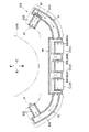
- the headrest S30 includes therein a cartridge housing portion 60, a first duct 61, a second duct 62, a fan 40, a control unit 65, a first cable 71, a second cable 72.
- the cartridge accommodating portion 60 is a portion that accommodates the cartridge C attached to the headrest S30.
- the cartridge housing portion 60 has a cartridge mounting portion 400 to which the cartridge C is detachably mounted.
- the cartridge mounting portion 400 is provided in an exposed state on the rear surface of the headrest S30. Details of the cartridge mounting portion 400 will be described later.
- the first duct 61 is a duct that communicates the intake port A2 and the cartridge mounting portion 400 .
- the air sucked from the intake port A2 passes through the first duct 61 and flows into the cartridge accommodating section 60 and further into the cartridge mounting section 400 .
- the first duct 61 is connected to the cartridge housing portion 60 .
- the first duct 61 includes a first pipe portion 61A having one end connected to the cartridge housing portion 60, and a second pipe portion 61B extending from the other end of the first pipe portion 61A toward the air inlet A2 of the headrest S30. including.
- the second duct 62 is a duct that communicates between the cartridge mounting portion 400 and the blower port A1.
- the air inside the cartridge mounting portion 400 passes through the inside of the cartridge containing portion 60 and the inside of the second duct 62 and is blown out from the blowing port A1.
- the second duct 62 is connected to the cartridge housing portion 60 .
- the second duct 62 includes a third pipe portion 62A, one end of which is connected to the cartridge housing portion 60, and a fourth pipe portion 62B that extends from the other end of the third pipe portion 62A toward the blower port A1 of the headrest S30. including.
- the fan 40 is a fan that forms an airflow inside the headrest S30 from the intake port A2, through the cartridge mounting portion 400, and toward the blow port A1. In other words, the fan 40 forms an airflow from the blower port A1 toward the intake port A2 on the front side of the headrest S30. In this embodiment, only one fan 40 is provided in the headrest S30.
- the fan 40 is arranged inside the first duct 61 . Specifically, the fan 40 is arranged at the left and right outer ends of the first pipe portion 61A, near the connecting portion between the first pipe portion 61A and the second pipe portion 61B. The fan 40 is arranged to face the intake port A2.
- the control unit 65 is a unit for controlling the fan 40, the cartridge C, and the like. As shown in FIG. 9, in this embodiment, the control unit 65 is arranged below the cartridge housing section 60 .
- a first cable 71 is a cable that connects the fan 40 and the control unit 65 .
- the first cable 71 has one end connected to the fan 40 and the other end connected to the control unit 65 .
- the first cable 71 is arranged along the first tube portion 61A of the first duct 61 and the cartridge housing portion 60 .
- the second cable 72 is a cable that connects the control unit 65 and a device provided outside the headrest S30.
- the second cable 72 is, for example, a cable for supplying power to the control unit 65 or the like, and includes a cable that connects the control unit 65 and a battery (not shown) mounted on the vehicle body.
- the second cable 72 is drawn outside the headrest S30 through the inside of one headrest pillar S31.
- the headrest S30 has a plurality of cartridge mounting portions 400. As shown in FIG. Specifically, the headrest S30 has three cartridge mounting portions 400 . One cartridge C is detachably attached to one cartridge attachment portion 400 .
- the three cartridge mounting portions 400 are arranged side by side.
- the three cartridge mounting portions 400 include a first cartridge mounting portion 400A, a second cartridge mounting portion 400B, and a third cartridge mounting portion 400C.
- the first cartridge mounting portion 400A is the rightmost cartridge mounting portion 400
- the third cartridge mounting portion 400C is the leftmost cartridge mounting portion 400.
- the second cartridge mounting portion 400B is the cartridge mounting portion 400 positioned between the first cartridge mounting portion 400A and the third cartridge mounting portion 400C.
- the cartridge mounting portion 400 (400A, 400B, 400C) is arranged in a portion of the headrest S30 located behind the head of the seated person. Specifically, the cartridge mounting portion 400 is arranged in a portion of the headrest S30 that supports the head of the seated person from behind. Specifically, the cartridge mounting portion 400 is arranged in the central portion of the headrest S30 in the left-right direction. The cartridge mounting portion 400 is arranged at the rear portion of the central portion in the left-right direction of the headrest S30.
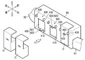
- each cartridge mounting portion 400 has a mounting opening 410, a cover 420, and a pair of left and right claw portions 430.
- the mounting opening 410 is an opening for mounting the cartridge C to the cartridge mounting portion 400 .
- the mounting opening 410 opens toward the rear. Thereby, the cartridge C can be mounted from behind in the mounting opening 410 of the cartridge mounting portion 400 .
- the cover 420 is a cover for opening and closing the mounting opening 410 .
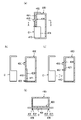
- the cover 420 is movable between an open position shown in FIG. 12(c) in which the mounting opening 410 is open and a closed position shown in FIG. 12(b) in which the mounting opening 410 is closed.
- cover 420 is vertically slidable between an open position and a closed position.
- the cover 420 has a cover body 421 that opens and closes the mounting opening 410, and a knob 422 that is gripped when the cover 420 is slid up and down.
- the knob 422 extends rearward from the left-right central portion of the lower end portion of the rear surface of the cover body 421 (see also FIG. 11).
- FIG. 12(d) is a diagram showing the XX section of FIG. 12(a).
- the claw portion 430 is a portion that holds the cartridge C while the cartridge C is mounted in the cartridge mounting portion 400 .
- the left and right claw portions 430 are provided with a predetermined space left and right.
- the left and right claw portions 430 are provided above the mounting opening 410 .
- the left and right claw portions 430 each have an arm portion 431 extending rearward and an engaging portion 432 projecting left and right inward from the rear end portion of the arm portion 431 .
- the left and right claw portions 430 are configured such that the arm portions 431 are elastically bent outward to the left and right when the cartridge C is attached or detached.
- the cover 420 When the cartridge C is attached to the cartridge attachment portion 400, the cover 420 is slid to the open position shown in FIG. 12(c) by grasping the knob 422 from the closed position shown in FIG. 12(b). . Then, while the cover 420 is held at the open position, the cartridge C is mounted in the mounting opening 410 from behind. Then, as shown in FIGS. 12A and 12D, the cartridge C can be mounted in the cartridge mounting portion 400 by mounting the cartridge C to the position where it is held by the claw portion 430. FIG.
- the cartridge C has a cartridge main body 470, a first extending portion 481, and a second extending portion 482.
- the cartridge body 470 is substantially box-shaped.
- the cartridge main body 470 has ventilation portions 484 on the left and right side surfaces 471 and 472, respectively.
- the ventilation part 484 is a part that communicates the inside and the outside of the cartridge C, more specifically, the inside and the outside of the cartridge main body 470, and has ventilation.
- the ventilation section 484 has a structure in which the openings 473 formed in the left and right side surfaces 471 and 472 of the cartridge body 470 are covered with a mesh 485 having ventilation.
- vent 484 may be formed by opening 473 without being covered with mesh 485 .
- the number of openings on each side surface 471, 472 is not limited to one, and may be plural.
- the right and left walls of the cartridge main body 470 may be formed in a mesh pattern or lattice pattern to form a plurality of openings (through holes) that communicate the inside and the outside of the cartridge main body 470 .
- multiple openings may be covered with a mesh.
- the ventilation part 484 may be formed not only on the side surfaces 471 and 472 of the cartridge main body 470, but also on the upper surface or the like.
- the airflow passing through the cartridge mounting part 400 can pass therethrough while the cartridge C is mounted in the cartridge mounting part 400 (see FIG. 10).
- the first extending portion 481 is a portion extending upward from the rear end portion of the upper surface of the cartridge body 470 .
- the first extending portion 481 is formed with a hole 483 into which the knob 422 of the cover 420 is inserted when the cartridge C is attached to the cartridge attachment portion 400 (see FIG. 11). Further, when the cartridge C is attached to the cartridge attachment portion 400, the claw portion 430 of the cartridge attachment portion 400 holds the first extending portion 481 (see FIG. 12D).
- the second extending portion 482 is a portion extending forward from the upper end portion of the front surface of the first extending portion 481 . As shown in FIG. 12(a), the second extending portion 482 sandwiches the rear wall of the cartridge mounting portion 400 with the cartridge main body 470 when the cartridge C is mounted in the cartridge mounting portion 400. .
- cartridge C has a fragrance source 810 within cartridge body 470, as shown in FIG. 14(a).
- the fragrance source 810 is a device for adding fragrance to the air passing through the cartridge C.
- FIG. 14(a) fragrance source 810 includes scented beads 811 and case 812 that houses beads 811 .
- Case 812 has air permeability.
- the specific configuration of the fragrance source 810 is not limited to this.
- the beads 811 instead of the beads 811, a structure having a sheet of scented paper or the like may be used.
- the cartridge C has a temperature controller 820 inside the cartridge body 470, as shown in FIG. 14(b).
- the temperature adjuster 820 is a device that changes the temperature of the air passing through the cartridge C by cooling or heating the air passing through the cartridge C.
- FIG. As an example, temperature regulator 820 includes Peltier element 821 .
- the Peltier element 821 has the function of cooling or heating the air passing through the cartridge C. As shown in FIG.
- the specific configuration of the temperature adjuster 820 is not limited to this.
- the temperature adjuster 820 may have a structure that includes an element that only has the function of cooling the air passing through the cartridge C, or an element that only has the function of heating the air passing through the cartridge C. It may be a structure.
- the temperature adjuster 820 may have a structure including a heater instead of the Peltier element 821 .
- the cartridge C has an ion generator 830 in the cartridge body 470, as shown in FIG. 14(c).
- the ion generator 830 is a device for adding ions to the air passing through the cartridge C.
- FIG. As an example, ion generator 830 includes a needle-shaped discharge electrode 831 .
- the discharge electrode 831 generates ions in the air by applying voltage.
- the cartridge C has an air purifier 840 inside the cartridge body 470, as shown in FIG. 14(d).
- the air purifier 840 is a device for purifying the air passing through the cartridge C.
- air purifier 840 includes ultraviolet lamp 841 .
- the ultraviolet lamp 841 has a function of sterilizing the air passing through the cartridge C with ultraviolet rays.
- an air purifier 840 has a discharge electrode 831 as shown in FIG. may be Further, the air purifier 840 may have a structure having a filter, activated carbon, or the like for removing dust, odorous components, bacteria, etc. in the air passing through the cartridge C. FIG. Also, the air purifier 840 may have a structure in which two or more of the above ultraviolet lamps 841, discharge electrodes 831, filters, activated carbon, etc. are combined.
- each cartridge mounting portion 400 further has ventilation openings 440 formed in left and right side walls, and a pair of left and right shutters 450 for opening and closing the ventilation openings 440 .
- the ventilation opening 440 is an opening for exposing the ventilation section 484 of the cartridge C mounted in the cartridge mounting section 400 .
- the shutter 450 opens and closes the ventilation section 484 of the cartridge C mounted in the cartridge mounting section 400 by opening and closing the ventilation opening 440 .
- the shutter 450 is movable between a fully closed position, shown in FIG. 15(a), in which the vent opening 440 is fully closed, and a fully open position, shown in FIG. 15(b), in which the vent opening 440 is fully opened.
- the shutter 450 is vertically slidable between a fully closed position and a fully open position.
- the headrest S30 has a shutter driving mechanism 460 for driving the shutter 450.
- the shutter driving mechanism 460 is provided corresponding to each cartridge mounting portion 400 (400A, 400B, 400C (see FIG. 10)).
- the shutter drive mechanism 460 includes, for example, a drive pulley 461, a driven pulley 462, an endless belt 463 stretched between the drive pulley 461 and the driven pulley 462, and a forward and reverse rotatable belt that drives the drive pulley 461. and a reduction gear (not shown) that reduces the driving force of the motor 464 and transmits it to the driving pulley 461 .
- Shutter 450 is attached to belt 463 .
- the control unit 65 controls the fan 40, the cartridges C (C1, C2, C3) mounted in the cartridge mounting section 400, and the motors 464 (464A, 464B, 464C) of the shutter driving mechanism 460. It has the function of controlling In this embodiment, the control unit 65 controls the temperature regulator 820 (see FIG. 14(b)), the ion generator 830 (see FIG. 14(c)), the air purifier, and the cartridge C attached to the cartridge attachment portion 400. It is also possible to control the ON/OFF and output of the device 840 (see FIG. 14(d)).
- the first motor 464A shown in FIG. 17 is the motor 464 of the shutter driving mechanism 460 corresponding to the first cartridge mounting portion 400A
- the second motor 464B is the shutter driving motor corresponding to the second cartridge mounting portion 400B
- the third motor 464C is the motor 464 of the shutter driving mechanism 460 corresponding to the third cartridge mounting portion 400C.
- the first cartridge C1 is the cartridge C mounted in the first cartridge mounting portion 400A
- the second cartridge C2 is the cartridge C mounted in the second cartridge mounting portion 400B
- the third cartridge C3 is: This is the cartridge C mounted in the third cartridge mounting portion 400C.
- the operation unit 91 is a device for the seated person to turn on/off the fan 40, adjust the air volume, turn on/off the devices provided in the cartridge C, adjust the output, open/close the shutter 450, open the shutter 450, and the like.
- the operation unit 91 includes switches, buttons, a touch panel, and the like for operating these.
- the operation unit 91 can be arranged, for example, on the left and right side surfaces of the headrest S30, the instrument panel of the vehicle, the door of the vehicle, and the like.
- the communication unit 92 is a device that enables short-range wireless communication such as Bluetooth (registered trademark) and Wi-Fi (registered trademark).
- short-range wireless communication such as Bluetooth (registered trademark) and Wi-Fi (registered trademark).
- the communication unit 92 can be arranged inside the headrest S30.
- the communication section 92 can be arranged below the cartridge housing section 60 together with the control unit 65 (see FIG. 9).
- the communication unit 92 may be provided outside the headrest S ⁇ b>30 , for example, in the vehicle body, and connected to the control unit 65 by the second cable 72 .
- the control unit 65 not only controls the fan 40, the cartridge C, and the shutter 450 based on the operation of the seated person, but also controls the fan 40 and the cartridge C based on information input from devices arranged inside and outside the headrest S30. , the shutter 450 may be automatically controlled.
- control unit 65 determines, based on the road information input from the car navigation system installed in the vehicle, that the road ahead has many curves where motion sickness is likely to occur, the control unit 65 can prevent motion sickness.
- the fan 40, the cartridge C, and the shutter 450 are controlled so as to make it difficult to occur.
- the control unit 65 controls the shutter 450 of the cartridge mounting section 400 to which the cartridge C is mounted. to drive the fan 40.
- the mint-scented air can be blown out from the blower port A1 of the headrest S30, and motion sickness is less likely to occur.
- the control unit 65 opens the shutter 450 of the cartridge mounting section 400 to which the cartridge C is mounted, and drives the fan 40. At the same time, the air passing through the cartridge C is cooled by driving the temperature adjuster 820 . As a result, cold air can be blown out from the blower port A1 of the headrest S30, and motion sickness can be prevented.
- the cartridge mounting portion 400 is arranged in the portion of the headrest S30 located behind the head of the seated person, so that the cartridge C can be easily replaced. .
- the cartridge C can be attached to the cartridge attachment portion 400 from behind, the attachment and detachment of the cartridge C can be facilitated.
- the cartridge C can be removed without once removing the other adjacent cartridge C. Since it can be attached and detached individually, the attachment and detachment work of the cartridge C can be easily performed.
- the mounting opening 410 can be closed by the cover 420 when the cartridge C is not mounted. As a result, for example, it is possible to prevent dust from entering the cartridge mounting portion 400 through the mounting opening 410 .
- the cartridge mounting portion 400 has the claw portion 430 , it is possible to prevent the mounted cartridge C from coming off the cartridge mounting portion 400 .
- the airflow passing through the cartridge mounting portion 400 can be switched between a state in which the airflow passes through the ventilation portion 484 of the cartridge C and a state in which it does not pass through the ventilation portion 484. You can switch whether to use the function or not. Further, in a configuration having a plurality of cartridge mounting portions 400 as in this embodiment, the cartridge C to be used can be switched by switching the open/closed state of the shutter 450 for each cartridge mounting portion 400 .
- the cartridge C has the fragrance source 810, when the cartridge C is attached to the cartridge attachment portion 400, the scented air can be blown out from the air outlet A1 of the headrest S30.
- the cartridge C having the fragrance source 810 is detachable, it is possible to change the type of fragrance according to the situation or preference.
- the cartridge C has the temperature adjuster 820, by attaching the cartridge C to the cartridge attachment portion 400, temperature-adjusted air such as warm air or cold air can be blown out from the air outlet A1 of the headrest S30. can be done.
- the cartridge C since the cartridge C has the ion generator 830, by mounting the cartridge C on the cartridge mounting portion 400, air to which ions are added can be blown out from the air outlet A1 of the headrest S30.
- the cartridge C since the cartridge C has the air purifier 840, by mounting the cartridge C on the cartridge mounting portion 400, purified air can be blown out from the air outlet A1 of the headrest S30.
- FIG. 18 a fourth embodiment will be described mainly with reference to FIGS. 18 and 19.
- FIG. 18 differences from the third embodiment described above will be described in detail, and descriptions of the same points as in the third embodiment will be omitted by, for example, assigning the same reference numerals to the same components. .
- the cartridge housing section 60 has three cartridge mounting sections 400 arranged side by side.
- Each cartridge mounting portion 400 has a mounting opening 910 and a cover 920 .
- the mounting opening 910 is an opening for mounting the cartridge C to the cartridge mounting portion 400 .
- the mounting opening 910 opens upward. Accordingly, in this embodiment, the cartridge C can be mounted from above in the mounting opening 910 of the cartridge mounting portion 400 .
- the cartridge mounting portion 400 is provided with its upper surface exposed to the outside of the headrest S30.
- the cover 920 is a cover for opening and closing the mounting opening 910.
- the cover 920 is movable between an open position shown in FIG. 19(b) in which the mounting opening 910 is opened and a closed position shown in FIG. 19(a) in which the mounting opening 910 is closed.
- cover 920 is rotatable between an open position and a closed position.
- the cover 920 can move between the closed position shown in FIG. 19A and the open position shown in FIG. It is rotatable up and down.
- the headrest S30 has a torsion spring 930 as an example of a biasing member.
- the torsion spring 930 is a spring that biases the cover 920 to the closed position shown in FIG. 19(a).
- the torsion spring 930 is arranged such that the coil portion is wound around the rotation shaft 920A, one end is in contact with the cover 920, and the other end is in contact with the wall of the cartridge mounting portion 400.
- the cartridge C When mounting the cartridge C to the cartridge mounting portion 400, the cartridge C is mounted from top to bottom in the mounting opening 910 as shown in FIG. 19(a). At this time, the cover 920 is pushed by the cartridge C to rotate from the closed position to the open position, and as shown in FIG. located in the open position.
- the cover 920 When the cartridge C in the state shown in FIG. 19B is lifted and removed from the cartridge mounting portion 400, the cover 920 is rotated from the open position toward the closed position by the biasing force of the torsion spring 930. . Then, as shown in FIG. 19A, when the cartridge C is removed from the cartridge mounting portion 400, the cover 920 is positioned at the closed position.
- the cartridge C can be mounted on the cartridge mounting portion 400 from above, the attachment and detachment of the cartridge C can be facilitated.
- the cartridges C can be individually attached and detached without removing the other adjacent cartridges C once. Therefore, the attachment/detachment operation of the cartridge C can be easily performed.
- the torsion spring 930 biases the cover 920 for opening and closing the mounting opening 910 of the cartridge mounting portion 400 to the closed position, the mounting opening 910 can be automatically closed by the cover 920 when the cartridge C is removed. can. As a result, forgetting to close the cover 920 can be prevented. As a result, it is possible to more reliably prevent dust and the like from entering the cartridge mounting portion 400 through the mounting opening 910 .
- cartridge C may have a deodorizer.
- the deodorizer is a device for removing odors from the air passing through the cartridge C, and includes a deodorizing filter and the like.
- the control unit 65 measures the odor of the air in the vehicle with the odor sensors provided in the headrest S30 and the vehicle body, and detects when the measured value of the odor sensor exceeds a predetermined value.
- the fan 40 may be driven for a predetermined period of time to pass the air taken in from the intake port A2 through the cartridge C and then blow it out from the air blow port A1, thereby deodorizing the interior of the vehicle. .
- a deodorizer for deodorizing the inside of the vehicle may be arranged, for example, in the first duct 61 instead of the cartridge C. According to this, since it is not necessary to mount the cartridge C having the deodorant to the cartridge mounting portion 400, the cartridge mounting portion 400 can be reserved for the cartridge C having other functions. For the same reason, the temperature adjuster 820, the ion generator 830, the air purifier 840, etc. of the third and fourth embodiments may be arranged inside the first duct 61 or inside the second duct 62.
- one cartridge has one function, but the present invention is not limited to this, and one cartridge may have multiple functions.
- the cartridge may have two or more devices having different functions among the fragrance source, temperature adjuster, ion generator, air purifier, deodorizer, and the like.
- the cartridge may be configured to have both an ion generator and an air purifier.
- the shutter 450 that slides up and down was exemplified as a shutter for opening and closing the ventilation section of the cartridge, but it is not limited to this.
- the shutter 950 has a plurality of blades 951 like a so-called louver. C) may be configured to open and close.
- a configuration without a shutter may be used.
- the headrest S30 is configured to have three cartridge mounting portions 400, but is not limited to this.
- the headrest may have two cartridge mounting portions, or may have four or more cartridge mounting portions.
- the headrest may be configured to have only one cartridge mounting portion 400 .
- the torsion spring 930 was exemplified as the biasing member that biases the cover 920 to the closed position, but the present invention is not limited to this.
- the biasing member may be a compression coil spring, a tension coil spring, a leaf spring, or the like.
- a configuration without the biasing member may be used.
- the cover may be detachable from the cartridge mounting section, and may be a cover that closes the opening when mounted on the cartridge mounting section and opens the opening when removed from the cartridge mounting section.
- the cover may be formed by a part of the skin of the headrest that covers the frame and the cushioning material of the headrest.
- the configuration may be such that the cover is not provided.
- the cartridge C can be mounted on the cartridge mounting portion 400 from behind, and in the fourth embodiment, the cartridge C can be mounted on the cartridge mounting portion 400 from above.
- the cartridge may be configured to be mountable from the left or right of the cartridge mounting portion.
- the cartridge mounting/removing direction may be parallel to the front-rear direction (horizontal direction), or may be slightly tilted up, down, left, or right with respect to the front-rear direction (horizontal direction).
- the cartridge mounting/removing direction may be parallel to the up-down direction (vertical direction), or may be slightly slanted forward, backward, left, or right with respect to the up-down direction (vertical direction).
- the cartridge mounting and demounting direction may be parallel to the left-right direction (horizontal direction), or may be slightly tilted in the front-rear and up-down directions with respect to the left-right direction (horizontal direction). good too.
- the specific configuration of the claw portion that holds the cartridge is not limited to the configuration of the above embodiment.
- the claw portion 430 is provided in a state of being exposed to the outside of the cartridge mounting portion 400, but this is not a limitation, and the claw portion may be provided inside the cartridge mounting portion. good.
- the configuration may be such that the claw portion is not provided.
- the fan 40 is arranged inside the first duct 61, but it is not limited to this.
- the fan may be placed inside the second duct 62 or inside the cartridge housing portion 60 .
- the headrest S30 has only one fan 40, but the present invention is not limited to this, and the headrest may have a plurality of fans.
- the headrest may comprise two fans, one fan being arranged in the first duct and the other fan being arranged in the second duct.
- a plurality of fans may be arranged in the first duct, and a plurality of fans may be arranged in the second duct.
- the cartridge mounting portion 400, the first duct 61 and the second duct 62 are provided separately, but the present invention is not limited to this.
- the configuration may be such that the cartridge mounting portion, the first duct and the second duct are integrated.
- the cartridge mounting portion 400 is provided in a state of being exposed to the outside, but it is not limited to this.
- the cartridge mounting portion may be normally covered with a part of the skin of the headrest or the like, and may be provided so as to be exposed when the cartridge is mounted.
- the power generation device described in the first embodiment may be provided in at least one of the seat portion S1, the backrest S2 and the headrest S30. In that case, electric power can be supplied to the control unit 65, the fan 40, the motor 464, etc. via the electric wires such as the first cable 71, the second cable 72, and the like.
- the seat portion S1, the backrest S2 and the headrest S30 are provided separately, but the present invention is not limited to this.
- a seat in which a backrest and a headrest are integrated may be used.
- the seat may be a seat in which the seat portion and the backrest are integrated.
- the seat may be a seat in which the seat portion, backrest and headrest are all integrated.
- the vehicle seat SV mounted in an automobile was exemplified as the seat, but the seat may be a vehicle seat mounted in a vehicle other than an automobile, such as a railway vehicle, a ship, an aircraft, or the like. . Also, the seat is not limited to a vehicle seat, and may be a seat used in an amusement facility, a relaxation facility, or at home, for example.
- the seat system SYS1 includes a seat S, an obstacle detection sensor SE1, and a controller 30A.
- the seat S is mounted on a vehicle CR equipped with a recognition unit 35 that recognizes the size of luggage of the occupant.
- the recognition unit 35 is a sensor for detecting luggage carried by a passenger outside the vehicle CR, and is composed of a camera or the like.
- the recognition unit 35 analyzes an image obtained by photographing at least a predetermined area behind the vehicle CR, thereby determining whether the image is a luggage image showing a passenger carrying luggage.
- the recognition unit 35 specifies the maximum length of the luggage from the luggage image, and notifies the luggage information indicating the maximum length of the luggage and the recognition of the luggage carried by the occupant.
- the indicated recognition information is output to the control unit 30A.
- the detection by the recognition unit 35 may be performed all the time, or may be performed when an occupant approaches the vehicle CR. Whether or not the occupant has approached the vehicle CR can be determined, for example, by determining whether or not the occupant has approached the vehicle CR based on the radio waves of the key remote control of the vehicle CR held by the occupant.
- the seat S is arranged in front of the luggage compartment 36 located at the rear of the vehicle CR.
- the seat S is arranged behind the front row seats FS such as the driver's seat and the passenger's seat.
- the vehicle CR is a five-door type vehicle, and includes a total of four doors (not shown) located on the left and right sides of the vehicle CR, and a back door 37 located behind the luggage compartment 36 .
- the seat S includes a seat portion S1, a backrest S2, and a headrest S3.
- the seat portion S1, the backrest S2, and the headrest S3 each include a frame (seat frame) that forms a skeleton, a pad (pad main body) that covers the frame, and a skin (skin member) that covers the pad. have.
- the backrest S2 is rotatably supported by the seat S1.
- the seat S is movable in the front-rear direction by a slide rail (not shown).
- the seat S includes a first drive source such as a motor (not shown) for rotating the backrest S2.
- the seat S or the vehicle CR includes a second drive source such as a motor (not shown) that moves the seat S in the longitudinal direction.
- the first drive source and the second drive source are controlled by the controller 30A.
- the seat S can be switched between the normal state shown in FIG. 21 and the stored state shown in FIG.
- the normal state is a state in which an occupant can sit, that is, a state in which the backrest S2 stands up with respect to the seat portion S1, and the seat S is positioned at a position other than the most forward position.
- the stowed state is a state in which the stowage space in the passenger compartment is made larger than in the normal state.
- the stowed state refers to a state in which the backrest S2 is folded so as to face the seat portion S1 and the seat S is arranged at the most forward position.
- the obstacle detection sensor SE1 is a sensor that detects obstacles within the trajectory of the sheet S until it switches from the normal state to the storage state.
- the obstacle detection sensor SE1 is arranged between the skin of the seat portion S1 and the pad, and detects the presence or absence of an object on the seat surface of the seat portion S1.
- the obstacle detection sensor SE1 can detect an obstacle within the locus of rotation of the backrest S2 from the normal state to the stowed state.
- the obstacle detection sensor SE1 is, for example, a pressure sensor. In this embodiment, the obstacle detection sensor SE1 is also used as a seat belt reminder sensor that detects whether or not the passenger is sitting on the seat.
- the control unit 30A has a CPU, ROM, RAM, rewritable non-volatile memory, etc. (not shown), and executes processing based on pre-stored programs.
- 30 A of control parts can communicate with smart phone SP as an example of the portable terminal which a crew member can carry.
- the control unit 30A may be provided in the vehicle CR or may be provided in the seat S.
- the setting which enables communication between the control unit 30A and the smartphone SP is assumed to be performed in advance for the control unit 30A and the smartphone SP by the passenger.
- the control unit 30A can execute sheet storage processing for changing the state of the sheet S from the normal state to the stored state.
- the control section 30A has a function of determining whether or not to execute the sheet storage process based on the information from the recognition section 35 .
- the control unit 30A receives the recognition information and the parcel information from the recognition unit 35, it determines whether or not the maximum length of the parcel is greater than a predetermined value.
- the control unit 30A determines to execute the sheet storage process when determining that the maximum length of the package is greater than a predetermined value, and does not execute the sheet storage process when determining that it is equal to or less than the predetermined value.
- the predetermined value may be the luggage compartment length or the luggage compartment width when the seat S is in the normal state and the seat S is at the rearmost position. It may be the length of the diagonal line of the luggage compartment space.
- the controller 30A checks whether there is an obstacle within the trajectory of the sheet S based on information from the obstacle detection sensor SE1 before starting the sheet storage process. It has a function to determine whether or not If the control unit 30A determines that there is no obstacle, it starts the sheet storage process, and if it determines that there is an obstacle, it does not start the sheet storage process.
- the control unit 30A determines that there is an obstacle and decides not to start the seat storage process, the control unit 30A has a function of notifying the occupant of non-execution information indicating that the seat storage process will not be performed by the smartphone SP. have.
- the non-execution information may be, for example, audio information such as "The sheet was not stored.” emitted from the speaker of the smartphone SP, sound information such as a warning sound, Image information such as a message displayed on the screen of the SP or a warning display such as a red screen color may be used.
- the control unit 30A determines that there is no obstacle and determines to start the seat storage process, the control unit 30A has a function of notifying the occupant of the execution information indicating that the seat storage process will be performed by the smartphone SP. have.
- the execution information may be, for example, audio information such as "Sheets have been stored.”
- Image information such as a message displayed on the screen or a success indication such as a blue screen color may be used.
- the control unit 30A may operate the seat S in response to a request from the occupant.
- the request from the passenger may be output to the control unit 30A by the passenger operating an operation unit provided in the vehicle, or may be output to the control unit 30A by the passenger operating the smartphone SP.
- the operation of the smartphone SP may be an operation based on the passenger's voice.
- the occupant may manually return the retracted state to the normal state by operating a lever for operating the reclining mechanism, a lever for unlocking the slide movement, or the like.
- control unit 30A determines whether or not the sheet S is in the stored state (S51). If it is determined in step S51 that it is in the retracted state (Yes), the control section 30A terminates this process.
- step S51 If it is determined in step S51 that the baggage is not in the stowed state (No), the control section 30A determines whether or not the recognition section 35 has recognized the luggage of the passenger (S52). Specifically, the control unit 30A determines whether or not the recognition information and package information have been acquired from the recognition unit 35 in step S52.
- step S52 If it is determined in step S52 that the package has not been recognized (No), the control unit 30A terminates this process. If it is determined in step S52 that the baggage has been recognized (Yes), the control section 30A determines whether or not the maximum length of the baggage is greater than a predetermined value (S53).
- step S53 When it is determined in step S53 that the maximum length of the package is not greater than the predetermined value (No), the control section 30A determines not to execute the sheet storage process, and terminates this process. If it is determined in step S53 that the maximum length of the package is greater than the predetermined value (Yes), the control section 30A determines to execute sheet storage processing (S54).
- step S54 the control unit 30A determines whether or not there is an obstacle within the movement trajectory of the sheet S based on information from the obstacle detection sensor SE1 (S55). When it is determined that there is no obstacle in step S55 (Yes), the control unit 30A transmits execution information to the smart phone SP (S56). After step S56, the control unit 30A executes sheet storage processing (S57), and ends this processing. When it is determined that there is an obstacle in step S55 (No), the control unit 30A transmits non-execution information to the smartphone SP (S58), and terminates this process without executing the sheet storage process.
- the recognition unit 35 recognizes the luggage carried by the occupant, specifies the size of the luggage, The recognition information and package information are transmitted to the control section 30A.
- the control unit 30A determines that the maximum length of the baggage is smaller than a predetermined value based on the baggage information. the sheet storing process is not executed.
- the control unit 30A determines that the maximum length of the baggage is larger than a predetermined value based on the baggage information. is also large, and decides to execute the sheet storage process. Next, before starting the sheet storage process, the control unit 30A determines whether or not there is an obstacle on the rotation trajectory of the backrest S2 based on the information from the obstacle detection sensor SE1.
- the control unit 30A executes sheet storage processing to switch the sheet S to the stored state. Specifically, the controller 30A moves the seat S forward after folding the backrest S2 forward. Also, at this time, the control unit 30A transmits the execution information to the passenger's smartphone SP, and the smartphone SP notifies the passenger of the execution information by sound, image, vibration, or the like.
- the execution information transmitted from the control unit 30A to the smartphone SP may be, for example, information such as a flag indicating that the sheet storage process is to be executed.
- the smartphone SP receives the information sent from the control unit 30A, the smartphone SP notifies the passenger of execution information such as voice information such as "The seat has been stowed.”
- the control unit 30A determines to execute the sheet storage process. Do not execute sheet storage processing. Also, at this time, the control unit 30A transmits the non-execution information to the smartphone SP of the passenger, and the smartphone SP notifies the passenger of the non-execution information by sound, image, vibration, or the like.
- the non-execution information transmitted from the control unit 30A to the smartphone SP may be, for example, information such as a flag indicating that the sheet storage process is not to be executed.
- the smartphone SP when receiving the information sent from the control unit 30A, the smartphone SP notifies the occupant of non-execution information such as voice information such as "The seat was not stowed.”
- the following effects can be obtained in this embodiment.
- it is determined whether or not there is an obstacle within the movement locus of the sheet S based on information from the obstacle detection sensor SE1. Since the storage process is not started, it is possible to prevent the movement of the sheet S that is moved by the execution of the sheet storage process from being restricted by an obstacle. Therefore, it is possible to suppress the load on the driving source such as the motor for moving the sheet S.
- the obstacle detection sensor SE1 is also used as a seat belt reminder sensor, cost can be reduced.
- the backrest S2 In the stowed state, the backrest S2 is folded so as to face the seat portion S1, so that the stowage space in the passenger compartment can be made larger than in the normal state.
- the seat S which is arranged in front of the luggage compartment 36 located in the rear part of the vehicle CR, is arranged in front of the normal state in the stowed state, so the cargo room space can be made larger than in the normal state.
- the occupant If there is an obstacle on the locus of movement of the seat S, the occupant is notified of the non-execution information, so that the occupant outside the vehicle CR can move the seat S to the stowed state based on the notification of the non-execution information.
- the occupant Before opening the back door 37 of the vehicle CR, it is possible to know that it is not. Therefore, the occupant can unload the baggage they are carrying before opening the back door 37 of the vehicle CR.
- the occupant When there is no obstacle on the locus of movement of the seat S, the occupant is notified of the execution information. Before the back door 37 of the vehicle CR is opened, it is possible to know that the vehicle CR is there. Therefore, the passenger can open the back door 37 of the vehicle CR with peace of mind while carrying the luggage.
- the passenger can receive the non-execution information or the execution information. Easy to check.
- the stored state is the state in which the backrest is folded and the seat is arranged at the most forward position.
- the seat with the backrest folded is formed on the floor. It may be in a recess.
- the seat with the backrest folded is configured to be movable forward and downward, and in the process of switching from the normal state to the stowed state, the seat moves forward and downward after the backrest is folded. may be accommodated in the recess.
- the seat is not limited to the rear seat, and may be the front seat such as the driver's seat or the passenger's seat.
- the stored state may be a state in which the backrest is folded and the position in the front-rear direction is the same as in the normal state.
- the second row seat may be switched from the normal state to the stowed state by raising the hips or sliding forward.
- hip-up refers to a state in which the seat is rotated around pivot shafts positioned forwardly and downwardly of the seat so that the rear portion of the seat portion is positioned higher than in the normal state.
- the detection target of the recognition unit may be predetermined areas on the left and right outside of the vehicle. Also, in this case, the passenger can put the luggage in the vehicle by opening the side door. In addition, when the second row seats are hip-up or forward-slidable, the occupant can place luggage in the rear luggage compartment after opening the side door.
- the sheet storage process can also be performed for multiple sheets.
- the backrest of the front passenger seat is folded to be stored, the backrest of the rear seat is folded, and the rear seat is moved forward. It may be put in the storage state by moving to .
- larger items such as surfboards can be loaded into the vehicle.
- only the front or rear seats can be stowed, or both the front and rear seats can be stowed. Both can be stored.
- the control unit puts only the rear seats into the stowed state when the occupant with luggage is positioned behind the vehicle and the size of the luggage is larger than the first threshold.
- the control unit stores only the front seat. do.
- the control unit puts both the front seat and the rear seat into the stowed state regardless of the position of the occupant.
- the obstacle detection sensor may be a camera, radio wave sensor, capacitance sensor, or the like. If a camera or radio wave sensor is used, it is possible to detect obstacles within the sliding movement range of the seat. Also, the obstacle detection sensor may be configured by combining a plurality of sensors such as cameras. According to this, the obstacle can be detected more accurately.
- the power generation device described in the first embodiment may be provided in at least one of the seat portion S1 of the seat S, the backrest S2, and the headrest S3.
- the power generation device can be configured to supply power to the obstacle detection sensor SE1.
- the recognition unit may be provided inside the vehicle as in the above embodiment, or may be provided outside the vehicle. If an error occurs in the recognition unit, for example, the package cannot be recognized, the control unit may prohibit execution of the sheet storage process.
- the controller may prohibit the reclining process.
- the non-execution information/execution information may be notified by the vehicle's internal speaker, room lamp, or light installed outside the vehicle.
- control unit may stop the movement of the sheet and return it to its original state.
- a mode in which the seat storage process is executed and a mode in which the seat storage process is not executed may be switchable by the passenger.
- the control unit may be capable of executing an application program that uses the seat as a controller. In this case, the control unit may prohibit execution of the application program when the sheet is in the stored state.
- the mobile terminal may be a terminal other than the smartphone SP, such as a tablet terminal.
- the seat system SYS2 includes a seat S, a rear seat RS, an obstacle detection sensor SE2, and a controller 30B.
- the seat S and the rear seat RS are mounted on a vehicle CR that can switch between automatic driving and non-automatic driving.
- the seat configuration of the vehicle CR is a two-row specification, and the seat S is a first-row seat such as a driver's seat or a front passenger's seat.
- the rear seat RS is a seat in the second row and is arranged behind the seat S. As shown in FIG.
- the seat S and the rear seat RS each include a seat portion S1, a backrest S2, and a headrest S3.
- the seat portion S1, the backrest S2, and the headrest S3 each include a frame (seat frame) that forms a skeleton, a pad (pad main body) that covers the frame, and a skin (skin member) that covers the pad. have.
- the backrest S2 is rotatably supported by the seat S1.
- the seat S is movable in the front-rear direction by a slide rail (not shown).
- the seat S includes a first drive source such as a motor (not shown) for rotating the backrest S2.
- the seat S or the vehicle CR includes a second drive source such as a motor (not shown) that moves the seat S in the longitudinal direction.
- the first drive source and the second drive source are controlled by the controller 30B.
- the seat S can be switched between the normal state shown in FIG. 25 and the relaxed state shown in FIG.
- the normal state is a state in which an occupant can sit, that is, a state in which the backrest S2 stands up with respect to the seat portion S1, and the seat S is positioned at a position other than the rearmost position.
- the relaxed state refers to a state in which the backrest S2 is tilted more rearward than in the normal state and the seat S is arranged in the rear, more specifically, in the rearmost position than in the normal state. In the relaxed state, the backrest S2 of the seat S is positioned on the seat portion S1 of the rear seat RS.
- the obstacle detection sensor SE2 is a sensor that detects obstacles in the trajectory of the seat S until it switches from the normal state to the relaxed state.
- the obstacle detection sensor SE2 is arranged between the skin of the seat portion S1 of the rear seat RS and the pad, and detects the presence or absence of an object on the seat surface of the seat portion S1.
- the obstacle detection sensor SE2 is, for example, a pressure sensor. In this embodiment, the obstacle detection sensor SE2 is also used as a seat belt reminder sensor that detects whether or not the passenger is sitting on the seat.
- the control unit 30B has a CPU, ROM, RAM, rewritable non-volatile memory, etc. (not shown), and executes processing based on pre-stored programs.
- the control unit 30B can communicate with a smart phone SP as an example of a portable terminal that can be possessed by the passenger.
- the control unit 30B may be provided in the vehicle CR or may be provided in the seat S.
- the setting which enables communication between the control unit 30B and the smartphone SP is performed in advance by the crew member on the control unit 30B and the smartphone SP.
- the control unit 30B can execute reclining processing to change the state of the seat S from the normal state to the relaxed state. Specifically, the control unit 30B has a function of determining whether or not to execute the reclining process. Specifically, the control unit 30B determines to execute the reclining process by switching from non-automatic driving to automatic driving or by request from the passenger.
- the control unit 30B receives information indicating that non-automatic driving has switched to automatic driving from an ECU (Electronic Control Unit) (not shown) of the vehicle CR. It is decided to perform the reclining process when the second condition of having been met is satisfied.
- the passenger's request may be output to the control unit 30B by the passenger operating an operation unit provided in the vehicle, or may be output to the control unit 30B by the passenger operating the smartphone SP. good too.
- the operation of the smartphone SP may be an operation based on the passenger's voice.
- the control unit 30B determines whether there is an obstacle within the trajectory of the seat S based on information from the obstacle detection sensor SE2 before starting the reclining process. has a function to determine The control unit 30B starts the reclining process when determining that there is no obstacle, and does not start the reclining process when determining that there is an obstacle.
- control unit 30B determines that there is an obstacle and decides not to start the reclining process, it has a function of notifying the occupant of non-execution information indicating that the reclining process will not be executed by the smartphone SP.
- the non-execution information may be, for example, audio information such as "The seat could not be changed to the relax mode" emitted from the speaker of the smartphone SP, or sound information such as a warning sound. , image information such as a message displayed on the screen of the smartphone SP or a warning display such as a red screen color.
- control unit 30B determines that there is no obstacle and decides to start the reclining process, it has a function of notifying the occupant of execution information indicating that the reclining process will be executed by the smartphone SP.
- the execution information may be, for example, audio information such as "seat has been changed to relax mode" emitted from the speaker of the smartphone SP, sound information such as a warning sound, Image information such as a message displayed on the screen of the SP or a success indication such as blue color of the screen may be used.
- the control unit 30B may operate the seat S in response to a request from the passenger.
- the request from the passenger may be output to the control unit 30B by the passenger operating an operation unit provided in the vehicle, or may be output to the control unit 30B by the passenger operating the smartphone SP. good.
- the occupant may manually return from the relaxed state to the normal state by operating a lever for operating the reclining mechanism, a lever for unlocking the slide movement, or the like.
- control unit 30B determines whether or not the automatic operation is being performed based on information from an ECU (not shown) (S61). If it is determined in step S61 that the automatic operation is not being performed (No), the control section 30B terminates this process.
- step S61 If it is determined that the automatic driving is being performed in step S61 (Yes), the control unit 30B determines whether or not there is a request (information) from the occupant to switch the state of the seat S to the relaxed state ( S62). If it is determined in step S62 that there is no request (No), the control section 30B terminates this process. If it is determined in step S62 that there is a request (Yes), the control section 30B determines whether the seat S is in a relaxed state (S63).
- step S63 If it is determined in step S63 that the user is in a relaxed state (Yes), the control unit 30B determines not to execute the reclining process, and terminates this process. If it is determined in step S63 that the user is not in the relaxed state (No), the control section 30B determines to perform the reclining process (S64).
- step S64 the control unit 30B determines whether or not there is an obstacle within the movement trajectory of the sheet S based on information from the obstacle detection sensor SE2 (S65). When it is determined that there is no obstacle in step S65 (Yes), the control unit 30B transmits execution information to the smart phone SP (S66). After step S66, the control unit 30B executes the reclining process (S67) and terminates this process. When it is determined that there is an obstacle in step S65 (No), the control unit 30B transmits non-execution information to the smartphone SP (S68), and terminates this process without executing the reclining process.
- control section 30B when the control unit 30B determines to perform the reclining process, the control unit 30B rotates the backrest S2 based on the information from the obstacle detection sensor SE2 before starting the reclining process. Determine whether or not there is an obstacle on the trajectory.
- the control unit 30B executes reclining processing to switch the seat S to the relaxed state, as shown in FIG. 28(a). . Specifically, the controller 30B moves the seat S rearward after tilting the backrest S2 backward. Also, at this time, the control unit 30B transmits the execution information to the passenger's smart phone SP, and the smart phone SP notifies the passenger of the execution information by sound, image, vibration, or the like.
- the execution information transmitted from the control unit 30B to the smartphone SP may be, for example, information such as a flag indicating that the reclining process is to be executed.
- the smartphone SP receives the information sent from the control unit 30B, the smartphone SP notifies the passenger of execution information such as voice information such as "The seat has been changed to the relax mode.”
- the control unit 30B executes the reclining process.
- the reclining process is not performed even though the user has decided to reclining.
- the control unit 30B transmits the non-execution information to the smartphone SP of the passenger, and the smartphone SP notifies the passenger of the non-execution information by sound, image, vibration, or the like.
- the non-execution information transmitted from the control unit 30B to the smartphone SP may be, for example, information such as a flag indicating that the reclining process is not to be executed.
- the smartphone SP when receiving the information sent from the control unit 30B, the smartphone SP notifies the occupant of non-execution information such as voice information such as "The seat could not be changed to the relax mode.”
- the following effects can be obtained in this embodiment.
- the obstacle detection sensor SE2 is also used as a seat belt reminder sensor, the cost can be reduced.
- the space in front of the seat S can be made larger than in the normal state, so that the occupant can be more relaxed.
- the non-execution information is notified to the occupant when there is an obstacle on the movement locus of the seat S, the occupant can know that the reclining process will not be executed.
- the occupant When there is no obstacle on the locus of movement of the seat S, the occupant is notified of the execution information, so that the occupant can know that the reclining process will be executed.
- the music played by the internal speaker of the vehicle CR can be played once. There is no need to perform control such as stopping.
- the relaxed state is defined as a state in which the backrest is tilted backward and the seat is arranged in the rearmost position.
- the position in the front-rear direction may be the same as in the normal state.
- the seat is not limited to the front seat, but may be the rear seat. If the vehicle has three rows of seats, it may be a seat in the third row.
- an obstacle detection sensor may detect an object in the luggage compartment.
- the obstacle detection sensor may be a camera, radio wave sensor, capacitance sensor, or the like. If a camera or radio wave sensor is used, it is possible to detect obstacles within the sliding movement range of the seat. Also, the obstacle detection sensor may be configured by combining a plurality of sensors such as cameras. According to this, the obstacle can be detected more accurately.
- the power generation device described in the first embodiment may be provided in at least one of the seat portion S1 of the seat S, the backrest S2, and the headrest S3.
- the power generation device can be configured to supply power to the obstacle detection sensor SE2.
- the non-execution information/execution information may be notified by the vehicle's internal speaker or room lamp.
- control unit may stop the movement of the seat and return it to its original state.
- the mobile terminal may be a terminal other than the smartphone SP, such as a tablet terminal.
- the controller may prohibit the reclining process.
- the control unit can determine to execute the reclining process when requested by the occupant, regardless of whether the vehicle is automatically driven or non-automatically driven, including when the vehicle is stopped.
- the ECU of the vehicle determines whether or not there is a divider on the road during automatic driving, and if it determines that there is a divider, outputs a request to the control unit to switch the seat state to the relaxed state.
- the control unit may be an ECU of the vehicle. In this case, the control unit may determine to perform the reclining process when the condition that the non-automatic operation is switched to the automatic operation and the condition that the separation strip exists are satisfied.
- the seat may be switchable between the first state and the second state.
- the obstacle detection sensor may detect an obstacle in the trajectory of the sheet from the first state to the second state.
- the control unit may be capable of executing attitude change processing for changing the state of the seat from the first state to the second state.
- the control unit determines whether or not there is an obstacle within the trajectory of the sheet based on information from the obstacle detection sensor before starting the attitude change process. If it is determined that there is no obstacle, the attitude change process is started, and if it is determined that there is an obstacle, the attitude change process is not started.
- the vehicle system SYS3 includes a pedal PD, a seat S, an obstacle detection sensor SE3, and a controller 30C.
- the pedal PD and seat S are mounted on a vehicle CR that can switch between automatic driving and non-automatic driving.
- the pedal PD is a pedal for operating the vehicle.
- the pedal PD may be at least one of an accelerator pedal and a brake pedal, but in this embodiment, it is both an accelerator pedal and a brake pedal.
- the pedal PD is movable between an operating position (position shown in FIG. 29) that can be operated by the leg of the passenger, and a storage position (position shown in FIG. 30) that is farther from the passenger than the operating position.
- the vehicle CR includes a pedal drive source such as a motor (not shown) for moving the pedal PD in the longitudinal direction.
- the pedal drive source is controlled by the controller 30C.
- the seat S is the driver's seat and is located behind the pedal PD.
- the seat S includes a seat portion S1, a backrest S2, and a headrest S3.
- the seat portion S1, the backrest S2, and the headrest S3 each include a frame (seat frame) that forms a skeleton, a pad (pad main body) that covers the frame, and a skin (skin member) that covers the pad. have.
- the backrest S2 is rotatably supported by the seat portion S1.
- the seat S has pressure sensors PS1 to PS6 for detecting the motion of the passenger sitting on the seat S.
- the pressure sensors PS1-PS3 are provided between the skin of the seat portion S1 and the pad, and the pressure sensors PS4-PS6 are provided between the skin of the backrest S2 and the pad.
- Each pair of pressure sensors PS1 to PS6 is provided symmetrically with respect to the center of the seat S in the left and right direction.
- the pressure sensors PS2 and PS3 are arranged at positions corresponding to the buttocks of the occupant on the seat portion S1. Specifically, the pressure sensor PS3 is arranged at a position corresponding to the lowest portion of the occupant's ischium where the load from the occupant is the greatest, and the pressure sensor PS2 is arranged at a position slightly in front of the pressure sensor PS3.
- the pressure sensors PS2 and PS3 acquire measured values of pressure from the buttocks of the occupant (hereinafter also referred to as "pressure values").
- the pressure sensor PS1 is arranged at a position far forward from the pressure sensors PS2 and PS3, specifically at a position corresponding to the thighs of the occupant. Pressure sensor PS1 obtains a measurement of pressure from the occupant's thigh.
- the pressure sensors PS4, PS5 are arranged under the backrest S2. Specifically, the pressure sensor PS4 is arranged at a position corresponding to the back of the passenger's waist, and the pressure sensor PS5 is arranged at a position slightly above the pressure sensor PS4. Pressure sensors PS4 and PS5 take measurements of pressure from the waist of the occupant.
- the pressure sensor PS6 is arranged at a position far upward from the pressure sensors PS4 and PS5, specifically at a position corresponding to the upper back of the occupant. Pressure sensor PS6 obtains a pressure measurement from a location corresponding to the upper back of the occupant.
- the pressure sensors PS1 to PS6 are elements whose electric resistance changes, for example, depending on the pressure from the outside, and the higher the pressure value, the higher or lower the voltage of the detection signal.
- the pressure sensors PS1 to PS6 output pressure values to the control section 30C.
- the obstacle detection sensor SE3 is a sensor that detects obstacles within the trajectory of the pedal PD from the operation position to the storage position.
- a camera, a radio wave sensor, or the like may be used as the obstacle detection sensor SE3.
- the control unit 30C has a CPU, ROM, RAM, rewritable non-volatile memory, etc. (not shown), and executes processing based on pre-stored programs.
- 30 C of control parts can communicate with smart phone SP as an example of the portable terminal which a crew member can carry.
- the control unit 30C may be provided in the vehicle CR or may be provided in the seat S.
- the setting which enables communication between the control unit 30C and the smartphone SP is performed in advance by the crew member on the control unit 30C and the smartphone SP.
- the smartphone SP acquires the pressure values acquired by the pressure sensors PS1 to PS6 (see FIG. 31) via the control unit 30C.
- An application program (hereinafter referred to as "application") using the seat S as a controller is installed in the smartphone SP, and the installed application can be executed.
- An application is, for example, a game application that provides a game.
- Game applications include, for example, a 100-meter run game.
- the 100m run game is a game in which the passenger sitting on the seat S runs the character displayed on the screen of the smartphone SP by alternately moving both legs up and down.
- the smartphone SP proceeds with the game by determining whether the occupant's legs are raised or lowered based on the pressure values from the left and right pressure sensors PS1.
- the smartphone SP outputs an application activation signal indicating that the application has been activated to the control unit 30C.
- the control unit 30C can execute a pedal retraction process for changing the position of the pedal PD from the operation position to the retracted position. Specifically, the control unit 30C has a function of determining whether or not to execute the pedal retraction process. Specifically, the control unit 30C determines to execute the pedal storage process on the condition that the non-automatic operation is switched to the automatic operation.
- control unit 30C receives information indicating that non-automatic driving has switched to automatic driving from an ECU (Electronic Control Unit) (not shown) of the vehicle CR as a first condition, and an application from the smartphone SP. It is decided to execute the pedal retraction process when the second condition of receiving the activation signal is satisfied.
- ECU Electronic Control Unit
- control unit 30C determines that there is an obstacle within the movement trajectory of the pedal PD based on information from the obstacle detection sensor SE3 before starting the pedal retraction process. It has a function to determine whether or not If the control unit 30C determines that there is no obstacle, it starts the pedal retraction process, and if it determines that there is an obstacle, it does not start the pedal retraction process.
- the smartphone SP When the control unit 30C determines that there is an obstacle and decides not to start the pedal retraction process, the smartphone SP notifies the occupant of non-execution information indicating that the pedal retraction process will not be executed. have.
- the non-execution information may be, for example, audio information such as "The pedal could not be retracted" emitted from the speaker of the smartphone SP, sound information such as a warning sound, or the like. It may be image information such as a message displayed on the screen or a warning display such as making the screen color red.
- the control unit 30C has a function of prohibiting the execution of the application when it determines that there is an obstacle and decides not to start the pedal retraction process. Specifically, when the control unit 30C determines not to start the pedal retraction process, the control unit 30C outputs to the smartphone SP a prohibition signal for prohibiting the smartphone SP from executing the application.
- the controller 30C determines that there is no obstacle and decides to start the pedal retraction process, it has a function of notifying the occupant of execution information indicating that the pedal retraction process will be executed by the smartphone SP. have.
- the execution information may be, for example, voice information such as "Pedals are retracted" emitted from the speaker of the smartphone SP, sound information such as a warning sound, or the screen of the smartphone SP. It may be image information such as a message displayed on the screen or a success indication such as making the screen blue.
- the controller 30C may operate the pedal PD in response to a request from the passenger.
- the request from the passenger may be output to the control unit 30C by the passenger operating an operation unit provided in the vehicle, or may be output to the control unit 30C by the passenger operating the smartphone SP. good.
- the operation of the smartphone SP may be an operation based on the passenger's voice.
- the control unit 30C may move the pedal PD from the retracted position to the operating position on condition that the automatic operation is switched to the non-automatic operation.
- control unit 30C determines whether or not the automatic operation is being performed based on information from the ECU (not shown) (S71). If it is determined in step S71 that the automatic operation is not being performed (No), the control unit 30C terminates this process.
- step S71 determines whether the pedal PD is in the operating position (S72). If it is determined in step S72 that it is not the operation position (No), the control unit 30C terminates this process. When it is determined to be the operation position in step S72 (Yes), the control unit 30C determines whether or not an application activation signal has been received from the smartphone SP (S73).
- step S73 If it is determined in step S73 that the application activation signal has not been received (No), the control unit 30C determines not to execute the pedal retraction process, and terminates this process. When it is determined that the application activation signal has been received in step S73 (Yes), the control unit 30C determines to execute the pedal retraction process (S74).
- step S74 the control unit 30C determines whether or not there is an obstacle within the movement trajectory of the pedal PD based on information from the obstacle detection sensor SE3 (S75). When it is determined that there is no obstacle in step S75 (Yes), the control unit 30C transmits execution information to the smart phone SP (S76). After step S76, the controller 30C executes a pedal retraction process (S77), and terminates this process. When it is determined that there is an obstacle in step S75 (No), the control unit 30C transmits non-execution information to the smartphone SP (S78), and transmits a prohibition signal for prohibiting execution of the application to the smartphone SP. (S79). After step S79, the control unit 30C terminates this process without executing the pedal retraction process.
- control section 30C determines to execute the pedal retraction process.
- the control unit 30C determines whether there is an obstacle on the movement locus of the pedal PD based on the information from the obstacle detection sensor SE3 before starting the pedal retraction process. determine whether
- the controller 30C executes the pedal retraction process to move the pedal PD from the operation position as shown in FIG. 32(a). Move it to the stowed position. Also, at this time, the control unit 30C transmits the execution information to the passenger's smartphone SP, and the smartphone SP notifies the passenger of the execution information by sound, image, vibration, or the like.
- the execution information transmitted from the control unit 30C to the smartphone SP may be, for example, information such as a flag indicating that the pedal retraction process is to be executed.
- the smartphone SP receives the information sent from the control unit 30C, it notifies the passenger of execution information such as voice information such as "Pedals are retracted.”
- the controller 30C decides to execute the pedal retraction process. Do not execute storage processing. Also, at this time, the control unit 30C transmits non-execution information and a prohibition signal to the passenger's smart phone SP.
- the smartphone SP notifies the passenger of the non-execution information by sound, image, vibration, etc., and prohibits the execution of the application.
- the non-execution information transmitted from the control unit 30C to the smartphone SP may be, for example, information such as a flag indicating not to execute the pedal retraction process.
- the smartphone SP receives the information sent from the control unit 30C, the smartphone SP notifies the passenger of non-execution information such as voice information such as "The pedal could not be retracted.”
- prohibiting the execution of the app includes terminating the app as well as temporarily stopping the app.
- the smartphone SP may forcibly terminate the running application, or display a screen that prompts the occupant to select whether to continue or cancel the execution of the application. may be displayed.
- the following effects can be obtained in this embodiment.
- it is determined whether or not there is an obstacle within the movement locus of the seat S based on information from the obstacle detection sensor SE3. Since the storing process is not started, it is possible to prevent the movement of the pedal PD, which is operated by executing the pedal storing process, from being restricted by an obstacle. Therefore, it is possible to suppress a load from being applied to a driving source such as a motor for operating the pedal PD.
- the space in front of the seat S becomes larger when the passenger uses the application, so that the seat S can be used as a controller.
- the passenger can easily operate the seat S.
- the application Since the execution of the application is prohibited when the pedal retraction process is not started due to the presence of an obstacle, the application is executed while the pedal PD is in the operating position, and the pedal PD does not hinder the movement of the passenger. can be suppressed.
- the music played by the internal speaker of the vehicle CR can be played once. There is no need to perform control such as stopping.
- the seventh embodiment can be used in various forms as exemplified below.
- the pedal is configured to move in the front-rear direction, but for example, the pedal may be moved in the vertical direction between the operating position and the retracted position, which is a position below the operating position.
- the floor may be provided with a recess for storing the pedal, and the pedal may be stored in the recess.
- the seat is not limited to the driver's seat, as long as it is placed behind the pedals.
- the seat may be a passenger seat and the pedal may be a brake pedal located in front of the passenger seat.
- the obstacle detection sensor may be a pressure sensor, capacitance sensor, or the like.
- a pressure sensor or a capacitance sensor When using a pressure sensor or a capacitance sensor, a plurality of sensors may be provided in the movement range of the pedal.
- the obstacle detection sensor may be configured by combining a plurality of sensors such as a pressure sensor and a camera. According to this, the obstacle can be detected more accurately.
- the power generation device described in the first embodiment may be provided in at least one of the seat portion S1 of the seat S, the backrest S2, and the headrest S3.
- the power generation device can be configured to, for example, be connected to the obstacle detection sensor such that the power generation device supplies power to the obstacle detection sensor.
- the non-execution information/execution information may be notified by the vehicle's internal speaker or room lamp.
- control unit may stop the movement of the pedal and return it to its original state.
- the mobile terminal may be a terminal other than the smartphone SP, such as a tablet terminal.
- the controller may prohibit the execution of the pedal retraction process.
- the control unit can determine to execute the pedal retraction process when the application is activated, including when the vehicle is stopped, regardless of whether the vehicle is driven automatically or non-automatically. Further, the control unit may decide to execute the pedal retraction process when requested by the passenger.
- the retraction of the pedals and the adjustment of the seat position may be performed automatically. Specifically, for example, when moving the pedal from the operating position to the retracted position, the seat may be moved to a position behind the current position.
- a sensor may be provided to detect an obstacle within the movement locus of the seat so that the pedal retraction process is not started even when there is an obstacle within the movement locus of the seat.
- the seat may be moved to a position behind the current position. That is, when the seat is movable between the first position and the second position behind the first position, and the controller determines that there is an obstacle and decides not to start the pedal retraction process.
- the seat may be moved from the first position to the second position. According to this, when the pedals cannot be accommodated, the seat is moved rearward to widen the space in front of the seat, so that the occupant can easily operate the seat as a controller.
- the pedal may be a pedal that can be operated by the passenger's hand.
- the seat system SYS4 includes a seat S, an obstacle detection sensor SE4, and a controller 30D.
- the seat S is mounted on a vehicle CR that can switch between automatic driving and non-automatic driving.
- the vehicle CR has a two-row seat configuration, and two seats S are arranged in the first row and two seats S in the second row with a space left and right.
- the driver's seat is also referred to as the first seat SA, the passenger's seat as the second seat SB, the seat behind the driver's seat as the third seat SC, and the seat behind the passenger's seat as the fourth seat SD.
- the seat S includes a seat portion S1, a backrest S2, and a headrest S3.
- the seat portion S1, the backrest S2, and the headrest S3 each include a frame (seat frame) that forms a skeleton, a pad (pad main body) that covers the frame, and a skin (skin member) that covers the pad. have.
- the seat S is rotatable around an axis along the vertical direction.
- the seat S is rotatable between a first orientation shown in FIG. 34 and a second orientation shown in FIG. 35 by a driving source such as a motor (not shown).
- the first direction is the direction in which the seat surface of the backrest S2 faces forward.
- the second orientation is an orientation in which the seat surface of the backrest S2 faces more inward in the left-right direction of the vehicle CR than in the first orientation.
- the obstacle detection sensor SE4 is a sensor that detects obstacles in the trajectory of the sheet S from the first orientation to the second orientation.
- the obstacle detection sensor SE4 is located in the ceiling of the vehicle CR, in the space (each of the seats SA to The range of the trajectory of SD) is assumed to be a camera capable of photographing.
- the control unit 30D has a CPU, ROM, RAM, rewritable non-volatile memory, etc. (not shown), and executes processing based on pre-stored programs.
- the control unit 30D can communicate with a tablet terminal TB as an example of a mobile terminal that can be carried by the passenger.
- the control unit 30D may be provided in the vehicle CR or may be provided in the seat S. It is assumed that the occupant has previously set the control unit 30D and the tablet terminal TB to enable communication between the control unit 30D and the tablet terminal TB. Further, the control unit 30D associates each tablet terminal TB with each sheet S and stores them. It is assumed that the occupant has previously set these associations to the control unit 30D.
- the control unit 30D can execute sheet orientation change processing for changing the orientation of the sheet S from the first orientation to the second orientation for each of the sheets SA to SD. Specifically, the control unit 30D has a function of determining whether or not to execute the sheet orientation changing process for each of the sheets SA to SD. Specifically, the control unit 30D determines to execute the sheet orientation change process when the first condition and the second condition are satisfied.
- the first condition is that the crew should be able to communicate with each other easily.
- the control unit 30D can determine whether or not to make it easier for the passengers to communicate with each other. Determine that the conditions are satisfied.
- whether or not to make it easier for passengers to communicate with each other is determined by, for example, when approximately the same content is displayed on a plurality of tablet terminals TB, the tablet terminals displaying approximately the same content are displayed. There is a method of determining that the occupants possessing TBs should be in a state where they can easily communicate with each other.
- the mode in which the seat S is rotated based on the content displayed on the tablet terminal TB possessed by each passenger is also referred to as communication mode. Execution of the communication mode is permitted or prohibited by mode selection performed in advance by the passenger with respect to the control unit 30D or the tablet terminal TB.
- the second condition is that there is a request from the passenger during automatic driving.
- the second condition includes the condition that the vehicle is in automatic operation and the condition that execution of the communication mode is permitted. It should be noted that the determination of whether the vehicle is in automatic operation can be made based on information obtained from an ECU (Electronic Control Unit) (not shown) of the vehicle CR, indicating that non-automatic operation has switched to automatic operation.
- ECU Electronic Control Unit
- control unit 30D determines whether an obstacle exists within the trajectory of the sheet S based on information from the obstacle detection sensor SE4 before starting the sheet orientation change process. It has a function to determine whether or not there is If the controller 30D determines that there is no obstacle, it starts the sheet orientation changing process, and if it determines that there is an obstacle, it does not start the sheet orientation changing process.
- the tablet terminal TB When the control unit 30D determines that there is an obstacle and decides not to start the seat orientation change process, the tablet terminal TB notifies the passenger of non-execution information indicating that the seat orientation change process will not be executed. It has the function to The non-execution information may be, for example, audio information such as "The seat could not be changed to communication mode" emitted from the speaker of the tablet terminal TB, or sound information such as a warning sound. However, it may be image information such as a message displayed on the screen of the tablet terminal TB or a warning display such as a red screen color.
- the tablet terminal TB When the controller 30D determines that there is no obstacle and decides to start the seat orientation change process, the tablet terminal TB notifies the occupant of execution information indicating that the seat orientation change process is to be executed. It has the function to The execution information may be, for example, audio information such as "The seat has been changed to communication mode" emitted from the speaker of the tablet terminal TB, or sound information such as a warning sound. It may be image information such as a message displayed on the screen of the tablet terminal TB or a success indication such as blue color of the screen.
- the control section 30D may move the seat S according to a request from the occupant.
- the request from the passenger may be output to the control unit 30D by the passenger operating an operation unit provided in the vehicle, or may be output to the control unit 30D by the passenger operating the tablet terminal TB. good too.
- the operation of the tablet terminal TB may be performed by the passenger's voice.
- the occupant may manually return the orientation of the seat S from the second orientation to the first orientation by operating a lever or the like that operates a mechanism for rotating the seat S.
- control unit 30D determines whether or not the automatic operation is being performed based on information from the ECU (not shown) (S81). If it is determined in step S81 that the automatic operation is not being performed (No), the control unit 30D terminates this process.
- step S81 determines whether there are a plurality of seats S for which execution of the communication mode is permitted (hereinafter also referred to as "target seats”). (S82). If it is determined in step S82 that there are not a plurality of target sheets (No), the control section 30D terminates this process. If it is determined in step S82 that there are a plurality of target seats (Yes), the control unit 30D selects a passenger (hereinafter also referred to as "target passenger”) who should communicate among the passengers on the plurality of target seats. (S83).
- target passenger a passenger who should communicate among the passengers on the plurality of target seats.
- step S83 When it is determined in step S83 that there are not a plurality of target passengers (No), the control unit 30D terminates this process. If it is determined in step S83 that there are a plurality of target occupants (Yes), the control unit 30D controls each of the seats S corresponding to the plurality of target occupants (hereinafter also referred to as "rotation target seats"). It is determined to execute sheet orientation change processing (S84).
- step S84 the control unit 30D determines whether or not there is an obstacle within the movement trajectories of the plurality of rotation target sheets based on information from the obstacle detection sensor SE4 (S85). When it is determined that there is no obstacle in step S85 (Yes), the control unit 30D transmits execution information to the tablet terminal TB of the target passenger (S86). After step S86, the control unit 30D executes sheet orientation change processing (S87), and ends this processing. When it is determined that there is an obstacle in step S85 (No), the control unit 30D transmits non-execution information to the tablet terminal TB of the target passenger (S88), and executes this process without executing the seat orientation change process. End the process.
- control section 30D As shown in FIG. 37, during automatic driving, when the seats S for which the communication mode is permitted are the second seat SB, the third seat SC, and the fourth seat SD, the control unit 30D Sheet SB, third sheet SC and fourth sheet SD are specified as target sheets. In the drawing, the contour of the target sheet is indicated by a thick line.
- control unit 30D acquires, from each tablet terminal TB, the information of the image currently displayed by the tablet terminal TB possessed by the occupant on the target seat (SB to SD), for example, and are substantially the same content, it is determined whether or not the occupants on the target seat should communicate with each other.
- the control unit 30D controls the third sheet
- the occupant on the SC and the fourth seat SD are specified as a plurality of seats to be rotated.
- the rotation target sheet is hatched with dots. Then, the control unit 30D determines to execute the sheet orientation changing process for a plurality of rotation target sheets.
- the control unit 30D determines to execute the sheet orientation change process
- the control unit 30D moves the rotation target sheet (SC, SD) based on the information from the obstacle detection sensor SE4 before starting the sheet orientation change process. Determine whether or not there is an obstacle on the trajectory.
- the control unit 30D transmits the execution information to each target passenger's tablet terminal TB, and the tablet terminal TB notifies each target passenger of the execution information by sound, image, vibration, or the like.
- the execution information transmitted from the control unit 30D to the tablet terminal TB may be, for example, information such as a flag indicating that the sheet orientation change process is to be executed.
- the tablet terminal TB when receiving the information sent from the control unit 30D, the tablet terminal TB notifies each target passenger of execution information such as voice information such as "The seat has been changed to the communication mode.”
- the display on the tablet terminal TB corresponding to the first sheet SA is substantially the same content as the display on each tablet terminal TB corresponding to the third sheet SC and the fourth sheet SD. Therefore, it is not determined whether the occupant on the first seat SA is the target occupant.
- the control unit 30D determines to execute the sheet orientation changing process. Despite this, sheet orientation change processing is not executed. Also, at this time, the control unit 30D transmits non-execution information to each target passenger's tablet terminal TB, and the tablet terminal TB notifies each target passenger of the non-execution information by sound, image, vibration, or the like.
- the non-execution information transmitted from the control unit 30D to the tablet terminal TB may be, for example, information such as a flag indicating that the sheet orientation change process is not to be executed.
- the tablet terminal TB when receiving the information sent from the control unit 30D, the tablet terminal TB notifies each target passenger of non-execution information such as voice information such as "The seat could not be changed to the communication mode.”
- the following effects can be obtained in this embodiment.
- Execution of the seat orientation change process is determined based on a request from the passenger (selection of communication mode) during automatic driving, so the orientation of the seat S is changed during non-automatic driving or when there is no request from the passenger. can be suppressed.
- the target occupant can know that the seat orientation change process will not be executed.
- the non-execution information or the execution information is notified by the tablet terminal TB carried by the target passenger, for example, compared to the case where the non-execution information or the execution information is notified by the internal speaker of the vehicle CR, the music played by the internal speaker of the vehicle CR There is no need to perform control such as temporarily stopping the
- the eighth embodiment described here can be used in various forms as exemplified below.
- the first direction is the forward direction
- the second direction is the direction inward in the lateral direction of the vehicle CR relative to the first direction.
- the second direction may be directed toward the inside in the left-right direction of the vehicle CR rather than forward.
- the control unit sets the seat in the first orientation when it determines that the passengers are not in a state in which communication should be performed, and sets the seat in the second orientation when it determines that the passengers should communicate with each other. good too.
- the occupants when the occupants are not in a state to communicate with each other, specifically, for example, when the contents displayed on the tablets held by the occupants are different, the occupants are directed outward in the left and right direction, and each occupant privacy can be ensured.
- the seats are not limited to all seats, and for example, only the seats in the first row or only the seats in the second row may be covered. Also, if the vehicle has a 3-row specification, it may be a seat in the 3rd row. Also, the number of sheets may be one instead of plural. In this case, one control unit that executes the sheet orientation changing process may be provided for each of the plurality of sheets.
- the obstacle detection sensor may be a pressure sensor, radio wave sensor, capacitance sensor, or the like.
- a pressure sensor or a capacitance sensor When a pressure sensor or a capacitance sensor is used, a plurality of sensors may be provided within the movement range of the sheet.
- the obstacle detection sensor may be configured by combining a plurality of sensors such as a pressure sensor and a camera. According to this, the obstacle can be detected more accurately.
- the power generation device described in the first embodiment may be provided in at least one of the seat portion S1, the backrest S2, and the headrest S3 of the seat S (SA to SD).
- the power generation device can be configured to, for example, be connected to the obstacle detection sensor such that the power generation device supplies power to the obstacle detection sensor.
- the non-execution information/execution information may be notified by the vehicle's internal speaker or room lamp.
- control unit may stop the movement of the sheet and return it to its original state.
- the mobile terminal may be a terminal other than the tablet terminal TB, such as a smartphone.
- the control unit may prohibit the execution of the seat orientation change process.
- the control unit can determine to execute the seat orientation change process when requested by the passenger, regardless of whether the vehicle is driven automatically or non-automatically, including when the vehicle is stopped.
- the seat is not limited to a seat provided in a vehicle, and may be a seat installed in a room, for example.
- a ninth embodiment, a tenth embodiment, an eleventh embodiment, and a twelfth embodiment relating to a seat having a seat portion on which a person sits and a backrest will be described.
- the seat can enhance the comfort of the person sitting on the seat (seated person).
- the seat is easy to perform necessary operations.
- the seat according to the ninth embodiment is configured as a two-seater sofa SS for home use.
- the sofa SS includes a seat body S0, an armrest AR as an example of a side portion, and a headrest SH.
- the seat body S0 has a seat portion S1 on which a person sits and a backrest S2.
- the seat portion S1 includes two seat cushions 100 and a lower support portion 310 as an example of a seat frame that supports the seat cushions 100 from below.
- the two seat cushions 100 are arranged side by side.
- the seat cushion 100 is placed on the lower support portion 310 for use, and is detachable from the lower support portion 310 .
- the backrest S2 includes two backrest cushions 200 and a rear support portion 320 as an example of a seat frame that supports the backrest cushions 200 from behind.
- the two backrest cushions 200 are arranged side by side.
- the backrest cushion 200 is placed in front of the rear support portion 320 for use, and is detachable from the rear support portion 320 .
- the armrests AR are located on the left and right sides of the seat S1, respectively, and protrude above the seat S1. Specifically, the left armrest AR is positioned to the left of the left seat cushion 100 and the right armrest AR is positioned to the right of the right seat cushion 100 . Each armrest AR protrudes above the upper surface of the seat cushion 100 placed on the lower support 310 (see FIG. 40).
- the armrest AR is detachable from the seat portion S1 and the backrest S2 (seat body S0). Specifically, the armrest AR is detachable from the lower support portion 310 and the rear support portion 320 . After being attached to the seat body S0, the armrest AR is fixed to at least one of the lower support portion 310 and the rear support portion 320 with screws (not shown).
- the headrest SH is a part that supports the part above the neck of the seated person.
- the headrest SH supports at least one of the neck and head of the seated person.
- Two headrests SH are provided side by side in correspondence with the left backrest cushion 200 and the right backrest cushion 200, respectively.
- Each of the two headrests SH includes a frame (seat frame) forming a skeleton, a pad main body covering the frame, and a skin member covering the pad main body.
- the headrest SH is detachable from the backrest S2. Specifically, the headrest SH is detachable from the rear support portion 320 .
- the left and right armrests AR, the left and right headrests SH, the lower support portion 310 and the rear support portion 320 constitute a base portion BS.
- the base portion BS has left and right armrests AR, a headrest SH, a lower support portion 310 and a rear support portion 320 .
- the sofa SS is configured with two seat cushions 100, two backrest cushions 200, and a base portion BS.
- the sofa SS further includes a blower 10 and an operation section 20 (see FIG. 40).
- the sofa SS has a substantially bilaterally symmetrical structure, so the structure of the left portion of the sofa SS, including the left seat cushion 100 and the backrest cushion 200, will be mainly described below. .
- the blower 10 is a device that blows out air by rotating an impeller, and is arranged inside the base portion BS. Specifically, the blower 10 is arranged inside the rear support portion 320 . In this embodiment, the blower 10 includes a first blower 11, a second blower 12, and a third blower 13 (see FIG. 43).
- the first blower 11 is arranged inside the rear support portion 320 and behind the seat cushion 100 .
- the second blower 12 is located inside the rear support 320 and behind the back cushion 200 .
- the second blower 12 is arranged above the first blower 11 .
- the third blower 13 shown in FIG. 43 is arranged inside the rear support portion 320 and in the vicinity of the left-right center portion of the rear support portion 320 .
- the seat cushion 100 includes a first cushion material 110 as an example of a pad body and a first skin 120 as an example of a skin member covering the first cushion material 110 .
- the first cushion material 110 has a seat cushion air passage 130 as a cushion air passage.
- the seat cushion air passage 130 is an air passage through which the air flow formed by the blower 10, specifically the first blower 11, passes.
- the seat cushion ventilation path 130 has a plurality of seat ventilation openings 131 as ventilation openings and a seat connection opening 132 .
- the seat ventilation opening 131 is open on the upper surface of the first cushion material 110 toward the seated person above.
- the seat portion connection opening 132 opens toward the rear rear support portion 320 on the rear surface of the first cushion member 110 .
- the seat ventilation openings 131 and the seat connection openings 132 communicate with each other.
- the seat vent opening 131 is provided at a position avoiding the left and right central portions of the seat cushion 100 .
- the seat ventilation opening 131 is provided at a position spaced from the left-right center LC1 of the seat cushion 100 to the left or right by a predetermined length L1 or more.
- the predetermined length L1 can be, for example, approximately one third of the length from the left-right center LC1 of the seat cushion 100 to the left or right end.
- the first skin 120 is breathable by forming a plurality of fine through-holes at positions corresponding to the seat ventilation openings 131, or is made of a breathable material.
- the backrest cushion 200 includes a second cushion material 210 as an example of a pad body and a second skin 220 as an example of a skin member covering the second cushion material 210 .
- the second cushion material 210 has a back cushion air passage 230 as a cushion air passage.
- the backrest cushion air passage 230 is an air passage through which the airflow generated by the blower 10, specifically the second blower 12, passes.
- the backrest cushion ventilation path 230 has a plurality of backrest ventilation openings 231 as ventilation openings and a backrest connection opening 232 .
- the backrest ventilation opening 231 is open on the front surface of the second cushion material 210 toward the seated person in front.
- the backrest connection opening 232 opens toward the rear support portion 320 on the rear surface of the second cushion material 210 .
- the plurality of backrest ventilation openings 231 and the backrest connection openings 232 communicate with each other.
- the backrest ventilation opening 231 is provided at a position avoiding the left and right central portions of the backrest cushion 200. As shown in FIG. Specifically, the backrest ventilation opening 231 is provided at a position spaced left or right from the left-right center LC2 of the backrest cushion 200 by a predetermined length L2 or more.
- the predetermined length L2 can be, for example, about one-third of the length from the left-right center LC2 of the backrest cushion 200 to the left or right end.
- the second skin 220 is breathable by forming a plurality of fine through-holes at positions corresponding to the backrest ventilation openings 231, or is made of a breathable material.
- each armrest AR includes a padding material 510 and a third skin 520 covering the padding material 510 .
- the padding 510 has side vents 530 .
- the side air passage 530 is an air passage through which the air flow formed by the blower 10, specifically the third blower 13, passes.
- the side vent passage 530 has a plurality of side vent openings 531 and side connection openings 532 .
- the side ventilation openings 531 and the side connection openings 532 are opened toward the left and right inner sides on the left and right inner surfaces of the pad material 510 .
- the side ventilation openings 531 open toward the seated occupant.
- the side connection opening 532 opens toward the rear support portion 320 behind the side ventilation opening 531 .
- the plurality of side ventilation openings 531 and the side connection openings 532 communicate with each other.
- the third skin 520 is breathable by forming a plurality of fine through-holes at positions corresponding to the side ventilation openings 531, or is made of a breathable material.
- the base part BS has a blower accommodation chamber 330, a first base part ventilation path 340, a second base part ventilation path 350, and a third base part ventilation path 360. ing.
- the blower housing chamber 330 is a portion in which the blower 10 is arranged, and is provided inside the rear support portion 320 .
- the blower accommodation chamber 330 includes a first blower accommodation chamber 331 in which the first blower 11 is arranged, a second blower accommodation chamber 332 in which the second blower 12 is arranged, and a third blower accommodation chamber in which the third blower 13 is arranged. chamber 333;
- the first base air passage 340 is an air passage that allows the blower 10 and the cushion air passages 130, 230 to communicate with each other.
- the first base air passage 340 is composed of a first duct 341 and a second duct 342 .
- the first duct 341 allows communication between the first blower 11 and the seat cushion air passage 130 . Specifically, the first duct 341 communicates between the first blower housing chamber 331 in which the first blower 11 is arranged and the seat cushion air passage 130 . As shown in FIG. 45, the first duct 341 has a first tubular portion 341A as a tubular portion projecting from the front surface of the rear support portion 320 at the front end.
- the first duct 341 of the seat cushion ventilation path 130 and the first base ventilation path 340 is arranged so that the first tubular part 341A is positioned in the seat of the seat cushion ventilation path 130 when the seat cushion 100 is attached to the base part BS. It is connected by entering into the connection opening 132 .
- the second duct 342 allows communication between the second blower 12 and the backrest cushion air passage 230 .
- the second duct 342 communicates the second blower housing chamber 332 in which the second blower 12 is arranged with the backrest cushion air passage 230 .
- the second duct 342 has a second tubular portion 342A as a tubular portion that bends forward and protrudes from the front surface of the rear support portion 320 at its upper end.
- the second duct 342 of the back cushion air passage 230 and the first base air passage 340 is connected to the back connection opening 232 of the back cushion air passage 230 when the back cushion 200 is attached to the base BS. It is connected by entering.
- the second base portion ventilation path 350 is a ventilation path that communicates the outside of the base portion BS with the blower 10 .
- the second base air passage 350 communicates the outside of the base BS with the blower accommodation chamber 330 .
- the second base air passage 350 has a base opening 351 that opens rearward under the base BS.
- the base portion opening 351 may be exposed on the surface of the base portion BS (sofa SS), or may be covered with a breathable cover or filter.
- the second base air passage 350 includes a first communication passage 352 that communicates between the base opening 351 and the first blower accommodation chamber 331, and a second communication passage that communicates the first blower accommodation chamber 331 and the second blower accommodation chamber 332. It has a communication path 353 . Further, as shown in FIG. 43 , the second base air passage 350 has a third communication passage 354 that communicates the second communication passage 353 and the third blower housing chamber 333 .
- the third base air passage 360 is an air passage that connects the third blower housing chamber 333 in which the third blower 13 is arranged and the side air passage 530 .
- the third base air passage 360 consists of ducts, and includes a left communication passage 361 that communicates the third blower housing chamber 333 and the left side air passage 530, and a third blower housing chamber 333 and the right side air passage. 530 and a right communication passage 362 that communicates with 530 .
- the left communication passage 361 and the right communication passage 362 each have a third cylindrical portion 363 protruding from the left and right side surfaces of the rear support portion 320 at the left and right outer ends.
- the side ventilation path 530 and the third base ventilation path 360 are connected by inserting the third tubular portion 363 into the side connection opening 532 of the armrest AR when the armrest AR is attached to the seat body S0.
- the blower 10 is provided to blow air toward the seated person from the ventilation openings 131, 231, 431.
- the first blower 11 and the second blower 12 are provided so as to send air from the second base air passage 350 toward the first base air passage 340 by rotation of the impeller.
- the third blower 13 is provided so as to send air from the second base section ventilation path 350 toward the third base section ventilation path 360 by rotation of the impeller.
- the operating section 20 is a section for the seated person to operate the blower 10 .
- the operation portion 20 is provided on the armrest AR of the base portion BS. Specifically, the operation unit 20 is provided near the front end of the upper surface of the left armrest AR.
- the operation unit 20 has a power switch 21, a selector switch 22, and an adjustment dial 23, for example.
- the blower 10 can be driven by turning on the power switch 21 .
- the changeover switch 22 is a switch for switching between driving and stopping the blower 10 in a state where the power switch 21 is turned on.
- the first changeover switch 22A when the first changeover switch 22A is turned on, the first blower 11 is driven to blow air from the seat cushion 100 toward the seated person.
- the first changeover switch 22A When the first changeover switch 22A is turned off, the first blower 11 stops and the air is no longer blown out from the seat cushion 100.
- the second blower 12 is driven to blow air from the backrest cushion 200 toward the seated person.
- the second changeover switch 22B is turned off, the second blower 12 is stopped and air is no longer blown from the front surface of the backrest cushion 200.
- the third selector switch 22C of the sofa SS is turned on, the third blower 13 is driven to blow air from the armrest AR toward the seated person.
- the third changeover switch 22C is turned off, the third blower 13 is stopped and air is no longer blown out from the armrest AR.
- the adjustment dial 23 is a dial for adjusting the flow rate of blown air by changing the rotational speed of the impeller of the blower 10, for example.
- the flow rate of blown air can be increased by turning the adjustment dial 23 clockwise, and the flow rate of blown air can be decreased by turning the adjustment dial 23 counterclockwise.
- the sofa SS further comprises electric wires 70 for supplying power to the blowers 11-13.
- the electric wire 70 is connected to the first blower 11 , the second blower 12 and the third blower 13 via the operation portion 20 .
- the electric wire 70 may be pulled out rearward from the rear surface of the armrest AR, and as shown in FIG. may be pulled out rearward from the rear surface of the .
- a connector 80 is used to connect the electric wire 70 at the point where the left armrest AR and the seat body S0 are separated.
- air can be blown out from the seat cushion 100 and the backrest cushion 200, so that the comfort of the seated person can be enhanced. Further, since the operating portion 20 is provided on the armrest AR, it is possible to make the operation easier than when the operating portion is provided on the backrest S2, for example.
- the ventilation openings 131, 231 are provided at positions left or right with a predetermined space or more from the left and right centers LC1, LC2 of the seat cushion 100 and the backrest cushion 200, the ventilation openings 131, 231 can be It can be provided at a position left and right away from the left and right centers LC1 and LC2 of the cushion 100 and the backrest cushion 200. - ⁇ As a result, it is possible to prevent the ventilation openings 131 and 231 from being blocked by the seated person. As a result, the air can be well blown out from the seat cushion 100 and the backrest cushion 200, so that the comfort of the seated person can be enhanced.
- the base opening 351 of the second base ventilation path 350 which opens to the outside, is arranged at an inconspicuous position on the sofa SS. be able to.
- the operation part 20 is provided on the upper surface of the armrest AR, it is possible to make the operation easier.
- the first base air passage 340 has cylindrical portions 341A and 342A at its ends, and the cylindrical portions 341A and 342A are connected to the cushion air passage 130. , 230 to connect the cushion air passages 130, 230 and the first base air passage 340, but the present invention is not limited to this.
- the cushion air passage contrary to the configuration of the ninth embodiment, has a tubular portion at the end, and the tubular portion of the cushion air passage enters the opening of the first base portion air passage, thereby A configuration in which the ventilation path and the first base portion ventilation path are connected may be employed.
- connection between the cushion air passage and the first base air passage is not limited to the configuration in which one cylindrical portion enters the other opening. It may be a configuration performed by entering the cylindrical portion of the.
- the seat cushion ventilation path 130 has a plurality of seat ventilation openings 131 and a seat connection opening 132 as a second opening.
- the seat connection opening 132 opens toward a first connection opening 343A of the first base air passage 340, which will be described later, on the rear surface of the first cushion member 110. As shown in FIG. 48, the seat cushion ventilation path 130 has a plurality of seat ventilation openings 131 and a seat connection opening 132 as a second opening.
- the seat connection opening 132 opens toward a first connection opening 343A of the first base air passage 340, which will be described later, on the rear surface of the first cushion member 110.
- the backrest cushion ventilation path 230 has a plurality of backrest ventilation openings 231 and a backrest connection opening 232 as a second opening.
- the backrest connection opening 232 opens toward a second connection opening 344A of the first base air passage 340, which will be described later, on the rear surface of the second cushion material 210. As shown in FIG.
- the first base air passage 340 includes a seat communication passage 343 that communicates a first blower housing chamber 331 in which the first blower 11 is arranged and the seat cushion air passage 130, and a second blower 12 in which the second blower 12 is arranged. It has a backrest communication passage 344 that connects the two-blower accommodation chamber 332 and the backrest cushion ventilation passage 230 .
- the seat portion communication passage 343 has a first connection opening 343A as a first opening at the end opposite to the end connected to the first blower accommodation chamber 331 .
- the first connection opening 343 ⁇ /b>A opens toward the seat connection opening 132 of the seat cushion air passage 130 .
- the seat cushion air passage 130 and the first base air passage 340 are communicated and connected by facing the seat connection opening 132 and the first connection opening 343A when the seat cushion 100 is attached to the base portion BS. .
- the backrest communication passage 344 has a second connection opening 344A as a first opening at the end opposite to the end connected to the second blower accommodation chamber 332 .
- the second connection opening 344A opens toward the backrest connection opening 232 of the backrest cushion air passage 230 .
- the backrest cushion air passage 230 and the first base air passage 340 are communicated and connected by facing the backrest connection opening 232 and the second connection opening 344A when the backrest cushion 200 is attached to the base portion BS.
- the sofa SS of the eleventh embodiment further includes a changing mechanism MC.
- the change mechanism MC can change the position of blowing air toward the seated person.
- the seat cushion 100 has a seat duct 140 and a first connecting pipe 150 that form a seat cushion air passage 130 .
- the seat duct 140 has a plurality of seat ventilation openings 131 that open toward the seated person, and is provided so as to slide forward, backward, leftward, and rightward by a changing mechanism MC.
- the first connection pipe 150 is a member that connects the seat duct 140 and the seat communication passage 343 of the first base ventilation passage 340, and has an extendable portion 151 that can be extended back and forth.
- the back cushion 200 has a back duct 240 and a second connecting tube 250 that form a back cushion air passage 230 .
- the backrest duct 240 has a plurality of backrest ventilation openings 231 that open toward the seated person, and is provided so as to slide vertically and horizontally by the changing mechanism MC.
- the second connecting pipe 250 is a member that connects the backrest duct 240 and the backrest communication passage 344 of the first base ventilation passage 340, and has an extendable portion 251 that can extend and retract vertically.
- the change mechanism MC includes a first slide mechanism MS1 that slides the seat duct 140 back and forth, a second slide mechanism MS2 that slides the seat duct 140 left and right, and a third slide mechanism MS2 that slides the backrest duct 240 up and down. It includes a slide mechanism MS3 and a fourth slide mechanism MS4 for sliding the backrest duct 240 left and right.
- the sofa SS has an operation unit 20 as shown in FIG.
- the operation unit 20 is provided on the upper surface of the armrest AR, as in the ninth embodiment.
- the operation unit 20 of the eleventh embodiment can operate the change mechanism MC.
- the operation unit 20 has an operation switch 24 in addition to a power switch 21 , a changeover switch 22 and an adjustment dial 23 .
- the operation switch 24 is a switch for operating the change mechanism MC, and consists of four switches 24A to 24D arranged in a cross shape on the front, back, left and right, and a substantially cross-shaped switch cover 24E.
- the switch cover 24E is provided so that the portion sandwiching the center swings up and down with the center as a fulcrum.
- the sofa SS pushes the switch 24A on the front side through the switch cover 24E, as shown in FIG.
- the duct 140 can be slid forward.
- the position at which air is blown out from the seat cushion 100 can be changed forward.
- the switch 24B on the rear side through the switch cover 24E as shown in FIG. 51(b)
- the seat section duct 140 can be slid rearward by the first slide mechanism MS1.
- the position at which air is blown out from the seat cushion 100 can be changed to the rear.
- the seat duct 140 can be slid to the left by the second slide mechanism MS2. As a result, the position at which air is blown out from the seat cushion 100 can be changed to the left. Also, by pressing the right switch 24D through the switch cover 24E, the seat duct 140 can be slid to the right by the second slide mechanism MS2. As a result, the position at which air is blown out from the seat cushion 100 can be changed to the right.
- the sofa SS pushes the switch 24A through the switch cover 24E, so that the backrest duct 240 is moved by the third slide mechanism MS3 as shown in FIG. 51(a). You can slide it down. As a result, the position at which air is blown out from the backrest cushion 200 can be changed downward.
- the backrest duct 240 can be slid upward by the third slide mechanism MS3 as shown in FIG. 51(b). As a result, the position at which air is blown out from the backrest cushion 200 can be changed upward.
- the backrest duct 240 can be slid to the left by the fourth slide mechanism MS4. Thereby, the position where the air is blown out from the backrest cushion 200 can be changed to the left. Further, by pressing the switch 24D through the switch cover 24E, the backrest duct 240 can be slid to the right by the fourth slide mechanism MS4. As a result, the position at which air is blown out from the backrest cushion 200 can be changed to the right.
- the change mechanism MC can change the position at which the air is blown out, so that the comfort of the seated person can be further enhanced.
- the seated person can change the air blowing position according to the preference of the seated person, so that the comfort of the seated person can be further enhanced.
- the changing mechanism MC is configured to be able to change the position of blowing air from the seat cushion 100 to the front, back, left, and right, but is not limited to this.
- the changing mechanism may be configured to change only the position from which air is blown from the seat cushion back and forth, or may be configured to be capable of changing only to the left and right the position from which air is blown from the seat cushion. .
- the changing mechanism MC is configured to be able to change the position of blowing air from the backrest cushion 200 vertically and horizontally, but is not limited to this.
- the changing mechanism may be configured so that the position of blowing air from the backrest cushion can be changed only up and down, or the position of blowing air from the backrest cushion can be changed only left and right.
- the change mechanism may be configured to change only the position at which air is blown from the seat cushion, or may be configured to change only the position at which air is blown from the backrest cushion.
- FIG. The twelfth embodiment differs from the eleventh embodiment in the change mechanism MC. Specifically, the changing mechanism MC of the twelfth embodiment can change the direction of blowing air toward the seated person instead of changing the position at which air is blown toward the seated person.
- the seat cushion 100 has a seat duct 160 and a first connecting pipe 170 that form a seat cushion air passage 130 .
- the seat duct 160 has a plurality of seat ventilation openings 131, and is provided so that the front and rear ends thereof can be vertically swung by the changing mechanism MC.
- the first connection pipe 170 is a member that connects the seat portion duct 160 and the seat portion communication passage 343, and has an extendable portion 171 that is vertically extendable.
- the back cushion 200 has a back duct 260 and a second connecting tube 270 that form a back cushion air passage 230 .
- the backrest duct 260 has a plurality of backrest ventilation openings 231, and is provided so that its upper and lower ends are swung back and forth by the changing mechanism MC.
- the second connection pipe 270 is a member that connects the backrest duct 260 and the backrest communication passage 344, and has an extendable portion 271 that can be extended back and forth.
- the change mechanism MC includes a seat rocking mechanism MD1 that rocks the seat duct 160 and a backrest rocking mechanism MD2 that rocks the backrest duct 260.
- the sofa SS can swing the seat duct 160 from upward to obliquely forward by means of the seat swing mechanism MD1. As a result, the direction in which air is blown out from the seat cushion 100 can be changed from upward to obliquely forward. Further, the sofa SS can swing the backrest duct 260 from obliquely upward to forward by the backrest swinging mechanism MD2. Thereby, the direction in which air is blown out from the backrest cushion 200 can be changed from obliquely upward to forward.
- the sofa SS can swing the seat duct 160 from upward to obliquely backward by the seat swing mechanism MD1.
- the sofa SS can further swing the backrest duct 260 upward by the backrest swinging mechanism MD2.
- the direction in which the air is blown out from the backrest cushion 200 can be further changed to obliquely upward.
- the direction in which the air is blown can be changed by the changing mechanism MC, so that the comfort of the seated person can be further enhanced.
- the change mechanism MC of the twelfth embodiment is desirably operable by the operation unit, as in the eleventh embodiment. According to this, the seated person can operate the operation unit to change the blowing direction of the air according to the preference of the seated person, so that the comfort of the seated person can be further enhanced.
- the change mechanism MC of the eleventh embodiment is configured to change only the position of blowing air
- the change mechanism MC of the twelfth embodiment is configured to change only the direction of blowing air. It is not limited to this.
- the change mechanism may be configured to change both the position of blowing air and the direction of blowing air.
- the ventilation openings 131 and 231 are provided only in the left and right sides of the left and right center portions of the seat cushion 100 and the backrest cushion 200, but the present invention is not limited to this.
- the ventilation openings may be provided not only in the left and right sides of the left and right central portion, but also in the left and right central portion.
- the electric wire 70 for supplying electric power to the blower 10 is pulled out rearward from the rear surface of the base portion BS including the armrest AR, but it is not limited to this.
- the electric wire may be pulled out to the left from the left side of the base or may be pulled out to the right from the right side of the base.
- the power generation device described in the first embodiment is used as the seat portion S1 of the seat (sofa SS), the backrest S2, and the headrest SH. At least one may be provided.
- the power generation device can be configured to supply power to the blowers 10 by connecting the power generation device to the blowers 10 (11, 12, 13), for example. In that case, the electric wire 70 pulled out to supply power to the blower 10 becomes unnecessary.
- the second base air passage 350 opens rearward at the lower portion of the base BS, but is not limited to this.
- the second base air passage may open rearward at the top of the base.
- the second base air passage may open leftward on the left side of the base, or may open rightward on the right side of the base.
- the second base air passage is directed downward on the lower surface of the lower support. It may be open.
- the blower 10 is arranged inside the rear support portion 320 of the base portion BS, but it is not limited to this.
- the blower 10 may be placed inside the lower support 310 .
- the blower 10 may be arranged inside the armrest AR (side portion).
- the first blower 11 is arranged inside the lower support portion 310
- the second blower 12 is arranged inside the rear support portion 320
- the third blower 13 is arranged inside each armrest AR. configuration may be used.
- the number of blowers is arbitrary.
- the sofa may be configured with a common blower to blow air from the seat and back cushions.
- the sofa may also be configured with a common blower to blow air from the seat cushions, back cushions and armrests.
- a plurality of blowers may be provided for blowing air from the seat cushion. The same applies to blowers for blowing air from the back cushions and armrests.
- the armrest AR (side portion) is configured to have the side air passage 530, but the present invention is not limited to this.
- the sofa SS does not include the side ventilation path 530, the third base ventilation path 360, the third blower 13, etc. of the above-described embodiment, and does not blow air from the armrest AR (side). good.
- the armrest AR (side portion) is detachable from the seat body S0, but is not limited to this, and may be, for example, non-detachable.
- both the seat cushion 100 and the backrest cushion 200 have the cushion air passages 130, 230, but the present invention is not limited to this.
- only one of the seat cushion and the backrest cushion may have a cushion ventilation path.
- the armrest AR (side portion) is located only on one of the left and right sides of one seat cushion 100, but this is not the only option.
- armrests (sides) may be located on both the left and right sides of one seat cushion 100 .
- the operation unit 20 is provided on the left armrest AR, but the present invention is not limited to this.
- the operation unit 20 may be provided on the right armrest AR.
- the operation unit 20 may be provided on both the left and right armrests AR.
- the operation unit 20 is provided on the upper surface of the armrest AR, but the configuration is not limited to this.
- the operation section may be configured to be provided on the left and right outer side or the left and right inner side of the armrest.
- the armrests AR side portions are positioned on both the left and right sides of the seat portion S1, but this is not the only option.
- the armrests (sides) may be located on only one of the left and right sides of the seat.
- the side part is the armrest AR, but it is not limited to this.
- the side portion may be a stand, a table, or the like, which is wider in the lateral direction than the armrest.
- the base portion BS has the armrest AR (side portion), but the present invention is not limited to this.
- the sofa SS may have a configuration in which the base portion BS does not have side portions.
- the operation part 20 is provided on the armrest AR (side part) of the base part BS, but it is not limited to this.
- the operation portion 20 may be provided on the left side surface of the base portion BS.
- the operation portion 20 is provided on the left side surface 311 of the lower support portion 310 .
- the operation section 20 may be provided on the right side surface of the base section BS (lower support section 310).
- the blower 10 is provided to blow air from the ventilation openings 131, 231, 431, but the present invention is not limited to this.
- a blower may be provided to draw air through the vent openings.
- the first blower 11 and the second blower 12 are arranged to blow air from the first base air passage 340 to the second base air passage 350 by the rotation of the impeller.
- the third blower 13 is provided so as to send air from the third base air passage 360 toward the second base air passage 350 by rotation of the impeller. .
- air can be sucked from the seat cushion 100 and the backrest cushion 200.
- the ventilation openings 131 and 231 are provided only in the left and right side portions of the left and right central portions of the seat cushion 100 and the backrest cushion 200, air can be well sucked from the seat cushion 100 and the backrest cushion 200. It can be carried out. Air can also be sucked from the armrest AR. And thereby, a comfortable feeling of a seated person can be improved.
- the blower may be provided so as to be able to switch between blowing air and sucking air, for example, by switching the rotation direction of the impeller.
- the sofa may have a configuration in which air is blown out from one of the seat portion and the backrest and air is sucked in from the other, for example.
- the sofa SS may have a configuration that allows air to be blown out or sucked in from the headrest SH.
- the sofa SS may further include a heater 50 as shown in FIG.
- the heater 50 is a sheet heater, a so-called planar heater.
- the heater 50 includes a seat heater 51A, a backrest heater 52A, a headrest heater 54A, and a leg heater 55. As shown in FIG.
- the seat heater 51A is a heater that heats the surface of the seat S1 facing the seated person, specifically, the upper surface of the seat S1.
- the seat heater 51A is mainly arranged at a position facing the seated person's buttocks and thighs, and heats the seated person's buttocks and thighs from below.
- the seat heater 51A is provided on each of the left and right seat cushions 100 .
- the seat heater 51A is arranged between the upper surface of the first cushion material 110 and the first skin 120. As shown in FIG. Also, the seat heater 51A is arranged in the center of the seat cushion 100 in the left-right direction.
- the seat heater 51A is arranged between a plurality of seat vent openings 131 provided in the left portion of the seat cushion 100 and a plurality of seat vent openings 131 provided in the right portion of the seat cushion 100. ing.
- the backrest heater 52A is a heater that heats the surface of the backrest S2 facing the seated person, specifically, the front surface of the backrest S2.
- the backrest heater 52A is mainly arranged at a position facing the waist and back of the seated person, and heats the waist and back of the seated person from behind.
- the backrest heaters 52A are provided on the left and right backrest cushions 200, respectively.
- the backrest heater 52A is arranged between the front surface of the second cushion material 210 and the second skin 220. As shown in FIG.
- the backrest heater 52A is arranged between a plurality of backrest ventilation openings 231 provided in the left portion of the backrest cushion 200 and a plurality of backrest ventilation openings 231 provided in the right portion of the backrest cushion 200. ⁇
- the headrest heater 54A is a heater that heats the surface of the headrest SH facing the seated person, specifically the front surface of the headrest SH.
- the headrest heater 54A is arranged at a position facing at least one of the head and neck of the seated person, and heats at least one of the head and neck of the seated person from behind.
- the headrest heater 54A is provided in each of the left and right headrests SH.
- the headrest heater 54A is arranged between the pad material of the headrest SH and the skin of the headrest SH.
- the headrest heater 54A includes a plurality of backrest ventilation openings 231 provided in the left portion of the backrest cushion 200 and a plurality of backrest ventilation openings provided in the right portion of the backrest cushion 200 in the left-right direction. 231.
- the leg heater 55 is a heater that heats the surface of the sofa SS that faces the legs of the seated person.
- the leg heaters 55 mainly heat the legs of the seated person below the knees.
- the leg heater 55 is provided to heat the front surface of the seat S1.
- the leg heater 55 is provided to heat the front surface of the seat cushion 100 .
- the operation unit 20 can be configured to be able to operate not only the blower 10 but also the heater 50.
- the headrest heater 54A may be provided so as to heat substantially the entire front surface of the headrest SH.
- the leg heater may be provided so as to heat not only the front surface of the seat portion S1 but also the surface of the lower support portion 310 facing the seated person, specifically, the front surface of the lower support portion 310. . Further, the leg heater may be provided so as to heat the surface of the ottoman that can be stored in the sofa SS, facing the seated person.
- the headrest SH is detachable with respect to the backrest S2 (seat body S0), but it is not limited to this, and may be, for example, nondetachable.
- the sofa SS is configured to include the headrest SH, but is not limited to this, and may be configured to not include the headrest, for example.
- the sofa SS for two people was exemplified as a seat, but it is not limited to this.
- the seat may be a one-seat sofa or a three-seat sofa.
- the seat is not limited to a sofa, and may be an armchair, for example.
- the seat is not limited to a seat for home use, and may be a seat used in an amusement facility or a relaxation facility, for example.
- the seat may be, for example, a vehicle seat or a vehicle seat mounted in an automobile, a railroad vehicle, a ship, an aircraft, or the like.
- the configuration having a blower capable of blowing out or sucking air as described above and the configuration in which the operation section is provided on the side surface of the base portion or the side portion of the base portion are applicable to at least the seat cushion and the backrest cushion. It can also be applied to a seat whose one side cannot be attached to and detached from the base portion.
- a seat having a seat portion and a backrest (see, for example, Japanese Unexamined Patent Application Publication No. 2020-192843) In the above, it is desirable to be able to enhance the comfort of the person sitting on the seat (seated person).
- a seat that can enhance the comfort of the occupant, and furthermore, can prevent the occupant from feeling uncomfortable.
- the seat according to the thirteenth embodiment is configured as a two-seat sofa SS for home use.
- the sofa SS includes a seat body S0, an armrest AR as an example of a side portion, and a headrest SH.
- the seat body S0 has a seat portion S1 on which a person sits and a backrest S2.
- the seat portion S1 includes two seat cushions 100 and a lower support portion 310 as an example of a seat frame that supports the seat cushions 100 from below.
- the two seat cushions 100 are arranged side by side.
- the seat cushion 100 is placed on the lower support portion 310 for use, and is detachable from the lower support portion 310 .
- the backrest S2 includes two backrest cushions 200 and a rear support portion 320 as an example of a seat frame that supports the backrest cushions 200 from behind.
- the two backrest cushions 200 are arranged side by side.
- the backrest cushion 200 is placed in front of the rear support portion 320 for use, and is detachable from the rear support portion 320 .
- the armrests AR are located on the left and right sides of the seat S1, respectively, and protrude above the seat S1. Specifically, the left armrest AR is positioned to the left of the left seat cushion 100 and the right armrest AR is positioned to the right of the right seat cushion 100 . Each armrest AR protrudes above the upper surface of the seat cushion 100 placed on the lower support 310 (see FIG. 56).
- the armrest AR is detachable from the seat portion S1 and the backrest S2 (seat body S0). Specifically, the armrest AR is detachable from the lower support portion 310 and the rear support portion 320 . After being attached to the seat body S0, the armrest AR is fixed to at least one of the lower support portion 310 and the rear support portion 320 with screws (not shown).
- the headrest SH is a part that supports the part above the neck of the seated person.
- the headrest SH supports at least one of the neck and head of the seated person.
- Two headrests SH are provided side by side in correspondence with the left backrest cushion 200 and the right backrest cushion 200, respectively.
- Each of the two headrests SH includes a frame (seat frame) forming a skeleton, a pad main body covering the frame, and a skin member covering the pad main body.
- the headrest SH is detachable from the backrest S2. Specifically, the headrest SH is detachable from the rear support portion 320 .
- the left and right armrests AR, the left and right headrests SH, the lower support portion 310 and the rear support portion 320 constitute a base portion BS.
- the base portion BS has left and right armrests AR, a headrest SH, a lower support portion 310 and a rear support portion 320 .
- the sofa SS is configured with two seat cushions 100, two backrest cushions 200, and a base portion BS.
- the sofa SS further includes a heater 50 and an operating section 90 .
- the heater 50 is a sheet heater, a so-called planar heater.
- the heaters 50 include a seat heater 51 , a backrest heater 52 , a side heater 53 and a headrest heater 54 .
- the seat heater 51 is a heater that heats the surface of the seat S1 facing the seated person, specifically, the upper surface of the seat S1.
- the seat heater 51 is mainly arranged at a position facing the buttocks and thighs of the seated person, and heats the buttocks and thighs of the seated person from below.
- the seat heater 51 is provided on each of the left and right seat cushions 100 .
- the seat cushion 100 includes a first cushion material 110 as an example of a pad body and a first skin 120 as an example of a skin member covering the first cushion material 110 .
- the seat heater 51 is arranged between the upper surface of the first cushion material 110 and the first skin 120 .
- the seat heater 51 includes a heater wire 511 that generates heat when energized, and a sheet-like base material 512 that supports the heater wire 511 .
- the base material 512 is made of nonwoven fabric or the like and has a plurality of cuts 513 .
- the cuts 513 extend forward and backward, respectively. Specifically, the cuts 513 each extend rearward from the front end of the substrate 512 .
- a plurality of cuts 513 are arranged side by side.
- the heater wire 511 is arranged along the contour of the substrate 512 including the cut 513 and fixed to the upper surface of the substrate 512 with an adhesive or the like.
- the backrest heater 52 is a heater that heats the surface of the backrest S2 facing the seated person, specifically, the front surface of the backrest S2.
- the backrest heater 52 is mainly arranged at a position facing the waist and back of the seated person, and heats the waist and back of the seated person from behind.
- the backrest heater 52 is provided on each of the left and right backrest cushions 200 (see FIG. 56).
- the backrest cushion 200 includes a second cushion material 210 as an example of a pad body, and a second skin 220 as an example of a skin member covering the second cushion material 210 .
- the backrest heater 52 is arranged between the front surface of the second cushion material 210 and the second skin 220 .
- the backrest heater 52 includes a heater wire 521 that generates heat when energized, and a sheet-like base material 522 that supports the heater wire 521.
- the base material 522 is made of nonwoven fabric or the like, and has a plurality of cuts 523 .
- the cuts 523 respectively extend vertically. Specifically, the cuts 523 each extend downward from the upper end of the base material 522 .
- a plurality of cuts 523 are arranged side by side.
- the heater wire 521 is arranged along the contour of the substrate 522 including the cut 523 and is fixed to the front surface of the substrate 522 with an adhesive or the like.
- the side heater 53 is a heater that heats the surface of the armrest AR facing the seated person.
- the side heaters 53 include an armrest heater 53A that heats the upper surface of the armrest AR, and an inner surface heater 53B that heats the left and right inner surfaces of the armrest AR.
- the armrest heater 53A and the inner surface heater 53B are provided on each of the left and right armrests AR.
- the armrest AR includes a first pad material 510 and a third skin 520 covering the first pad material 510 .
- Armrest heater 53A is arranged between the upper surface of first pad material 510 and third skin 520 .
- the inner surface heaters 53B are arranged between the left and right inner surfaces of the first pad material 510 and the third skin 520 .
- the inner surface heater 53B is arranged between the portion of the left and right inner surfaces of the first pad material 510 located above the upper portion of the seat cushion 100 and the third skin 520. ing.
- the inner surface heater 53B is arranged at a position facing the waist of the seated person.
- the inner surface heater 53B is arranged at a position facing the ilium of the seated person.
- the headrest heater 54 is a heater that heats the surface of the headrest SH facing the seated person, specifically, the front surface of the headrest SH.
- the headrest heater 54 is arranged at a position facing at least one of the head and neck of the seated person, and heats at least one of the head and neck of the seated person from behind.
- the headrest heater 54 is provided on each of the left and right headrests SH (see FIG. 56).
- the headrest SH includes a second padding material 610 and a fourth skin 620 covering the second padding material 610 .
- the headrest heater 54 is arranged between the front surface of the second pad material 610 and the fourth skin 620 .
- the operation part 90 is a part for the seated person to operate the heater 50 .
- the operation portion 90 is provided on the armrest AR of the base portion BS. Specifically, the operation unit 90 is provided near the front end of the upper surface of the left armrest AR.
- the right armrest heater 53A is provided so as to heat substantially the entire upper surface of the right armrest AR. It is provided only at a position behind the portion 90 .
- the operation unit 90 has, for example, a power switch 95, a plurality of selector switches 96, and an adjustment dial 97.
- the heater 50 can heat the surface facing the seated person by turning on the power switch 95 .
- the selector switch 96 is a switch for switching whether to perform heating by the heater 50 when the power switch 95 is turned on.
- Ten selector switches 96 are provided corresponding to the left and right seat heaters 51, the left and right backrest heaters 52, the left and right armrest heaters 53A, the left and right inner surface heaters 53B, and the left and right headrest heaters 54, respectively.
- the switch 96 corresponding to the left seat heater 51 when the switch 96 corresponding to the left seat heater 51 is turned on, the upper surface of the left seat cushion 100 can be heated by the left seat heater 51, and when the switch 96 is turned off, the left seat cushion 100 can be heated. The heating by the seat heater 51 can be stopped.
- the switch 96 corresponding to the right seat heater 51 is turned ON, the upper surface of the right seat cushion 100 can be heated by the right seat heater 51, and when the switch 96 is turned OFF, the right The heating by the seat heater 51 can be stopped.
- the heaters 52, 53A, 53B and 54 The same applies to the heaters 52, 53A, 53B and 54 as well.
- the adjustment dial 97 is a dial for adjusting the output of the heater 50.
- the output of the heater 50 can be increased by turning the adjustment dial 97 clockwise, and the output of the heater 50 can be decreased by turning the adjustment dial 97 counterclockwise.
- the output of the heater 50 is desirably adjustable for each of the heaters 51, 52, 53A, 53B, and 54 and for each left and right.
- the sofa SS further includes electric wires 70 for supplying power to the heater 50.
- the electric wire 70 is connected to the heater 50 via the operation portion 90 .
- the support portion 300 is a portion including the lower support portion 310 and the rear support portion 320 and supports the seat cushion 100 and the backrest cushion 200 of the seat body S0.
- Wires 70 include wires 700-710.
- An electric wire 701 connects the left seat heater 51 and the operation unit 90
- an electric wire 702 connects the right seat heater 51 and the operation unit 90 . Since the seat cushion 100 is detachable from the support portion 300 (lower support portion 310), the connection of the electric wire 701 at the point where the left seat cushion 100 and the support portion 300 are divided can be made by the connector 81 (as appropriate). See also FIG. 57). A connector 82 is used to connect the electric wire 702 at the point where the right seat cushion 100 and the support portion 300 are divided. Further, since the armrest AR is detachable from the support portion 300 (seat body S0), the electric wires 701 and 702 are connected by a connector 86 at the point where the support portion 300 and the left armrest AR are separated. there is
- An electric wire 703 connects the left backrest heater 52 and the operation unit 90
- an electric wire 704 connects the right backrest heater 52 and the operation unit 90 . Since the backrest cushion 200 is detachable from the support portion 300 (rear support portion 320), the electric wire 703 is connected by the connector 83 at the point where the left backrest cushion 200 and the support portion 300 are divided. .
- a connector 84 is used to connect the electric wire 704 at the point where the right backrest cushion 200 and the support portion 300 are divided.
- a connector 86 connects electric wires 703 and 704 at a location where the support portion 300 and the left armrest AR are separated.
- An electric wire 705 connects the left armrest heater 53A and the operation unit 90, and an electric wire 706 connects the left inner surface heater 53B and the operation unit 90.
- An electric wire 707 connects the right armrest heater 53A and the operation unit 90, and an electric wire 708 connects the right inner surface heater 53B and the operation unit 90.
- a connector 85 connects the electric wires 707 and 708 at the point where the right armrest AR and the support portion 300 are separated.
- a connector 86 connects electric wires 707 and 708 at a location where the support portion 300 and the left armrest AR are separated.
- An electric wire 709 connects the left headrest heater 54 and the operation unit 90
- an electric wire 710 connects the right headrest heater 54 and the operation unit 90 . Since the headrest SH is detachable from the support portion 300 (rear support portion 320), the connection of the electric wire 709 at the point where the left headrest SH and the support portion 300 are divided is performed by a connector (not shown). Moreover, the connection of the electric wire 710 at the part where the right headrest SH and the support portion 300 are divided is performed by a connector (not shown). A connector 86 connects electric wires 709 and 710 at a location where the support portion 300 and the left armrest AR are separated.
- the electric wire 700 connects the power plug, whose reference numeral is omitted, and the operation unit 90 .
- the electric wire 700 is pulled out from the support portion 300 .
- a connector 86 is used to connect the electric wire 700 at the point where the left armrest AR and the support portion 300 are divided.
- the electric wire 700 is drawn rearward from the rear surface of the left-right center portion of the support portion 300 (seat body S0).
- the electric wire 700 is connected to the rear surface of the seat main body S0 at a position below the position of the lower end of the seat cushion 100 attached to the lower support portion 310 (see one-dot chain line). pulled backwards from the
- the seat heater 51 can heat the upper surface of the seat S1 facing the occupant, and the backrest heater 52 can heat the front surface of the backrest S2 facing the occupant.
- the side heater 53 can heat the surface of the armrest AR facing the seated person.
- the armrest heater 53A can heat the upper surface of the armrest AR.
- the inner surface heaters 53B can heat the left and right inner surfaces of the armrest AR, the seated person can be warmed from the sides.
- the headrest heater 54 can heat the front surface of the headrest SH facing the seated person.
- the surface facing the seated person can be warmed by the heater 50, so that the comfort of the seated person can be enhanced.
- the substrates 512 and 522 of the seat heater 51 and the backrest heater 52 have a plurality of cuts 513 and 523, when a person sits on the seat S1 or leans against the backrest S2, the seat heater 51 is Since the seat back heater 52 is appropriately deformed, it is possible to prevent the seated person from feeling uncomfortable.
- the heater 50 may be configured to include a leg heater 55.
- the leg heater 55 is a heater that heats the surface of the sofa SS that faces the legs of the seated person.
- the leg heaters 55 mainly heat the legs of the seated person below the knees.
- the leg heater 55 is provided to heat the front surface of the seat S1.
- the leg heater 55 is provided to heat the front surface of the seat cushion 100 .
- the leg heater may be provided so as to heat not only the front surface of the seat S1 but also the surface of the lower support portion 310 facing the seated person, specifically, the front surface of the lower support portion 310.
- the leg heater may be provided so as to heat the surface of the ottoman that can be stored in the sofa SS, facing the seated person.
- the heater 50 may be configured to include an outer surface heater 56 .
- the outer surface heater 56 is a heater that heats the left and right outer surfaces of the sofa SS.
- the outer surface heater 56 is provided so as to heat the left and right outer surfaces of the armrest AR.
- the armrest AR (side portion) is detachable from the seat body S0, but is not limited to this, and may be, for example, non-detachable.
- the electric wire 70 (700) for supplying power to the heater 50 is pulled out rearward from the rear surface of the seat body S0, but the present invention is not limited to this.
- the electric wire may be pulled out from the armrest AR.
- the electric wires may be pulled out rearward from the rear surface of the armrest AR, or may be pulled out left and right outward from the left and right outer surfaces of the armrest AR.
- the sofa SS does not have an armrest (side portion) on at least one of the left and right sides of the seat portion S1
- the wires are attached to the left or right side of the seat body S0, for example, the left or right side of the lower support portion 310. It may be pulled out to the left or right from the side of the
- the power generation device described in the first embodiment may be provided in at least one of the seat portion S1, the backrest S2, and the headrest SH of the seat (sofa SS).
- a power generation device for example, may be connected to the heater 50 such that the power generation device supplies power to the heater 50 . In that case, the electric wire 70 pulled out to supply power to the heater 50 becomes unnecessary.
- the armrest AR (side portion) is located only on one of the left and right sides of one seat cushion 100, but this is not the only option.
- armrests (sides) may be located on both the left and right sides of one seat cushion 100 .
- the armrests AR side portions are positioned on both the left and right sides of the seat portion S1, but this is not the only option.
- the armrests (sides) may be located on only one of the left and right sides of the seat.
- the side part is the armrest AR, but it is not limited to this.
- the side portion may be a stand, a table, or the like, which is wider in the lateral direction than the armrest.
- the side heater 53 includes the armrest heater 53A and the inner surface heater 53B, but the configuration is not limited to this.
- the side heaters may be configured to include only the armrest heaters.
- the side heater may be configured to include only the inner surface heater.
- the operation unit 90 is provided on the left armrest AR, but the present invention is not limited to this.
- the operation unit 90 may be provided on the right armrest AR.
- the operation unit 90 may be provided on both the left and right armrests AR.
- the operating portion 90 is provided on the upper surface of the armrest AR, but the present invention is not limited to this.
- the operation part may be provided on the left and right outer side or the left and right inner side of the armrest AR.
- the operation portion is provided on the left or right side surface of the seat body S0, for example, the left or right side surface of the lower support portion 310. It may be provided on the right side or the like.
- the headrest heater 54 is provided to heat the front surface of the headrest SH, but the present invention is not limited to this.
- the headrest heater may include a heater that heats the front surface of the headrest and a heater that heats the upper surface of the headrest.
- the headrest heater may be provided so as to heat only the upper surface of the headrest.
- the headrest SH is detachable with respect to the backrest S2 (seat body S0), but it is not limited to this, and may be, for example, nondetachable.
- the heater 50 includes the headrest heater 54, but the present invention is not limited to this, and may be configured without the headrest heater, for example.
- the sofa SS is configured to include the headrest SH, but is not limited to this, and may be configured to not include the headrest, for example.
- the heater 50 includes the side heater 53, but the present invention is not limited to this, and may be configured without the side heater, for example.
- the sofa SS is configured to include side portions such as armrests AR, but the present invention is not limited to this, and may be configured not to include side portions.
- the configuration of the cuts 513 and 523 of the seat heater 51 and the backrest heater 52 is an example, and is not limited to the configuration of the embodiment.
- the number of notches is arbitrary.
- the direction in which the individual cuts extend and the direction in which the plurality of cuts are arranged may be different from those in the above-described embodiment, as long as the purpose of not giving the seated person a sense of discomfort can be achieved.
- both the seat heater 51 and the backrest heater 52 have heater wires 511, 521 and base materials 512, 522 provided with a plurality of cuts 513, 523. It is not limited to this.
- only one of the seat heater and the backrest heater may have a heater wire and a substrate provided with a plurality of cuts.
- the seat heater and the backrest heater may be planar heaters having a structure different from that of the above-described embodiment, instead of the structure having the heater wire and the base material.
- the heater 50 includes both the seat heater 51 and the backrest heater 52, but the present invention is not limited to this.
- the heater may be configured to include only one of a seat heater and a backrest heater.
- the seat cushion 100 is detachable from the lower support portion 310, but is not limited to this, and may be, for example, non-detachable.
- the backrest cushion 200 is detachable from the rear support portion 320, but is not limited to this, and may be, for example, non-removable.
- the sofa SS for two people was exemplified as a seat, but it is not limited to this.
- the seat may be a one-seat sofa or a three-seat sofa.
- the seat is not limited to a sofa, and may be an armchair, for example.
- the seat is not limited to a seat for home use, and may be a seat used in an amusement facility or a relaxation facility, for example.
- the seat may be, for example, a vehicle seat or a vehicle seat mounted in an automobile, a railroad vehicle, a ship, an aircraft, or the like.
Landscapes
- Engineering & Computer Science (AREA)
- Transportation (AREA)
- Mechanical Engineering (AREA)
- Aviation & Aerospace Engineering (AREA)
- Automation & Control Theory (AREA)
- Physics & Mathematics (AREA)
- General Physics & Mathematics (AREA)
- Chemical & Material Sciences (AREA)
- Combustion & Propulsion (AREA)
- Human Computer Interaction (AREA)
- Seats For Vehicles (AREA)
Abstract
着座者の動きにより効率的に発電する発電デバイスを備えるシートを提供する。シート(S)は、シートフレーム(F)と、シートフレーム(F)に被さったパッド本体(10)と、パッド本体(10)の着座者側に配置された振動によって発電する発電デバイス(G)と、を備える。一例として、シート(S)は、パッド本体(10)を覆う表皮部材(18)を備え、発電デバイス(G)は、パッド本体(10)と表皮部材(18)の間に位置する。望ましくは、パッド本体(10)は、着座者側の面に凹部(11)を有し、発電デバイス(G)は、凹部(11)の中に位置する。
Description
本開示は、シート、シートクッション、シートシステム、および車両システムに関する。
従来、振動により発電する発電デバイスをクッションパッドの下に設けたシートが知られている(特開2018-197035号公報)。このシートは、車両に搭載され、車両走行時の振動により発電デバイスで発電し、センサ等に給電している。
ところで、出願人はシートに設けた圧力センサを用いて、シートに座った着座者の動きを検出して、様々なものに応用することを検討している。このようなシートにおいても、着座者の動きによって、発電することが期待できる。しかしながら、従来技術のように、クッションパッドの下に発電デバイスを設けた場合には、発電デバイスに効率的に振動が伝わらず、効率的に発電することができないという問題がある。着座者の動きにより効率的に発電することができるシートおよびシートクッションを提供することが望まれている。
本開示の提案する一態様として、シートフレームと、シートフレームに被さったパッド本体と、振動によって発電する発電デバイスとを備える新しいシートを開示する。発電デバイスは、パッド本体の、着座者側に配置される。
このような構成によれば、振動によって発電する発電デバイスが、パッド本体の着座者側に配置されているので、着座者が動いた場合に、発電デバイスに振動が効率良く伝わる。このため、着座者の動きにより効率的に発電することができる。
前記したシートは、パッド本体を覆う表皮部材をさらに備えることができる。この場合、発電デバイスは、パッド本体と表皮部材の間に位置することができる。
パッド本体は、着座者側の面に凹部を有し、発電デバイスは、凹部の中に位置することが望ましい。
このような構成によれば、着座者が発電デバイスを異物として感じにくく、座り心地を向上させることができる。
シートは、発電デバイスを覆う、カバーパッドをさらに備えることが望ましい。
このような構成によれば、着座者が発電デバイスを異物として感じにくく、座り心地を向上させることができる。
シートは、パッド本体の、着座者側に配置された圧力センサをさらに備えることができる。この場合に、発電デバイスは、圧力センサに電力を供給するように接続されていてもよい。
シートが圧力センサを備える場合、圧力センサは、発電デバイスに重なって、発電デバイスの着座者側に配置されていてもよい。
このような構成によれば、圧力センサと発電デバイスを接続しやすいとともに、圧力センサの感度を損なうことがない。
別の態様として、シートの着座面に配置されて使用されるシートクッションを開示する。シートクッションは、パッド本体と、パッド本体の着座者側に配置された、振動によって発電する発電デバイスと、を備える。
このような構成によれば、振動によって発電する発電デバイスが、パッド本体の着座者側に配置されているので、着座者が動いた場合に、発電デバイスに振動が効率良く伝わる。このため、着座者の動きにより効率的に発電することができる。
シートクッションは、パッド本体を覆う表皮部材をさらに備えることができる。この場合、発電デバイスは、パッド本体と表皮部材の間に位置することができる。
パッド本体は、着座者側の面に凹部を有し、発電デバイスは、凹部の中に位置することが望ましい。
このような構成によれば、着座者が発電デバイスを異物として感じにくく、座り心地を向上させることができる。
シートクッションは、発電デバイスを覆う、カバーパッドをさらに備えることが望ましい。
このような構成によれば、着座者が発電デバイスを異物として感じにくく、座り心地を向上させることができる。
シートクッションは、パッド本体の、着座者側に配置された圧力センサをさらに備えることができる。この場合に、発電デバイスは、圧力センサに電力を供給するように接続されていてもよい。
シートクッションが圧力センサを備える場合、圧力センサは、発電デバイスに重なって、発電デバイスの着座者側に配置されていてもよい。
このような構成によれば、圧力センサと発電デバイスを接続しやすいとともに、圧力センサの感度を損なうことがない。
前記したシートおよびシートクッションによれば、着座者の動きにより効率的に発電することができる。また、効率良く発電できる発電デバイスを備えるシートおよびシートクッションの座り心地を向上させることができる。また、圧力センサを発電デバイスの着座者側に重ねて配置することで、圧力センサと発電デバイスを接続しやすいとともに、圧力センサの感度を損なうことがない。
発電デバイスが電力を供給する対象は、圧力センサに限られない。例えば、他の種類のセンサや、ブロワ、モータ、ヒータ、照明等、シート内外に設けられる様々な電気機器に発電デバイスを接続し、電力供給することができる。以下に列挙する諸態様においても、上述の発電デバイスによって電力を供給することができる。
一例として、座部、背もたれおよびヘッドレストを有するシート本体と、前記シート本体に着脱可能なカートリッジと、を備えるシートを開示する。前記ヘッドレストは、空気を吹き出すための送風口と、空気を吸い込むための吸気口と、前記カートリッジが着脱可能に装着されるカートリッジ装着部と、前記ヘッドレストの内部に前記吸気口から前記カートリッジ装着部を通過して前記送風口に向かう気流を形成するファンと、を有する。前記カートリッジは、前記カートリッジ装着部に装着された状態で前記カートリッジ装着部を通過する気流が通過可能であり、前記カートリッジ装着部は、前記ヘッドレストの、着座者の頭部の後ろに位置する部分に配置されている。
このような構成によれば、カートリッジ装着部が、ヘッドレストの、着座者の頭部の後ろに位置する部分に配置されていることで、カートリッジを容易に交換することができる。また、座部、背もたれおよびヘッドレストの少なくとも一つに発電デバイスを設け、ファンに接続することで、ファンに電力を供給することができる。
前記したシートにおいて、前記カートリッジは、前記カートリッジ装着部に対して後ろまたは上から装着可能である構成とすることができる。
これによれば、カートリッジの着脱作業を行いやすくすることができる。
前記したシートにおいて、前記ヘッドレストは、前記カートリッジ装着部を複数有する構成とすることができる。
これによれば、ヘッドレストに機能や種類などが異なる複数のカートリッジを装着することができる。これにより、カートリッジ装着部の数の範囲内で、使用するカートリッジを、取り替えることなく、状況や好みなどに応じて切り替えることが可能となる。
前記したシートにおいて、前記カートリッジ装着部は、前記カートリッジを装着するための開口を有し、前記ヘッドレストは、前記開口を開く開位置と、前記開口を閉じる閉位置との間で移動可能なカバーを有する構成とすることができる。
これによれば、カートリッジを装着しないで使用する場合にはカバーによってカートリッジ装着部の開口を閉じておくことができる。
前記したシートにおいて、前記ヘッドレストは、前記カバーを前記閉位置に付勢する付勢部材を有する構成とすることができる。
これによれば、カートリッジを取り外したときにカートリッジ装着部の開口をカバーによって自動的に閉じることができる。これにより、カバーの閉め忘れを防止することができる。
前記したシートにおいて、前記カートリッジ装着部は、前記カートリッジが装着された状態で前記カートリッジを保持する爪部を有する構成とすることができる。
これによれば、装着されたカートリッジがカートリッジ装着部から外れてしまうのを抑制することができる。
前記したシートにおいて、前記カートリッジは、当該カートリッジの内部と外部を連通する通気部であって、前記カートリッジ装着部に装着された状態で前記カートリッジ装着部を通過する気流が通過可能な通気部を有する構成とすることができる。
前記したシートにおいて、前記カートリッジ装着部は、前記通気部を開閉するシャッタを有する構成とすることができる。
これによれば、シャッタを開閉することで、カートリッジ装着部を通過する気流が、カートリッジの通気部を通過する状態と、通気部を通過しない状態とに切り替えることができるので、カートリッジの機能を使用するか否かを切り替えることができる。また、カートリッジ装着部を複数有する構成では、カートリッジ装着部ごとにシャッタの開閉状態を切り替えることで、使用するカートリッジを切り替えることができる。
前記したシートにおいて、前記ヘッドレストは、前記吸気口と前記カートリッジ装着部を連通する第1ダクトと、前記カートリッジ装着部と前記送風口とを連通する第2ダクトと、を有する構成とすることができる。
前記したシートにおいて、前記カートリッジは、芳香源、温度調整器、イオン発生器および空気清浄器の少なくとも1つを有する構成とすることができる。
他の例として、乗員の荷物の大きさを認識する認識部を備えた車両に搭載されるシートであって、乗員が着座可能な通常状態と、前記通常状態よりも車室内の収納空間を大きくする収納状態と、に切替可能なシートと、前記通常状態から前記収納状態に切り替わるまでの前記シートの軌跡内にある障害物を検出する障害物検出センサと、前記シートの状態を前記通常状態から前記収納状態に変更するシート収納処理を実行可能であり、前記シート収納処理の実行の可否を決定する制御部と、を備えるシートシステムを開示する。
前記制御部は、前記認識部からの情報に基づいて前記シート収納処理を実行することを決定した場合には、前記シート収納処理を開始する前に、前記障害物検出センサからの情報に基づいて前記軌跡内に障害物があるか否かを判定し、障害物がないと判定した場合には、前記シート収納処理を開始し、障害物があると判定した場合には、前記シート収納処理を開始しない。
前記制御部は、前記認識部からの情報に基づいて前記シート収納処理を実行することを決定した場合には、前記シート収納処理を開始する前に、前記障害物検出センサからの情報に基づいて前記軌跡内に障害物があるか否かを判定し、障害物がないと判定した場合には、前記シート収納処理を開始し、障害物があると判定した場合には、前記シート収納処理を開始しない。
この構成によれば、シート収納処理を開始する前に、障害物検出センサからの情報に基づいて軌跡内に障害物があるか否かを判定し、障害物があると判定した場合には、シート収納処理を開始しないので、シート収納処理の実行によって動作するシートの動きが障害物で規制されるのを抑制することができる。また、シートに発電デバイスを設け、障害物検出センサに接続することで、障害物検出センサに電力を供給することができる。
また、前記障害物検出センサは、前記シートの座面上の物の有無を検出してもよい。
この構成によれば、障害物検出センサとして、例えばシートに乗員が座っているか否かを検出する、シートベルトリマインダのセンサと兼用することができるので、コストの低下を図ることができる。
また、前記シートは、座部と、前記座部に対して回動可能な背もたれとを備え、前記収納状態において、前記背もたれは、前記座部と対面するように折り畳まれていてもよい。
この構成によれば、収納状態において、背もたれが座部と対面するように折り畳まれるので、通常状態よりも車室内の収納空間を大きくすることができる。
また、前記シートは、前記車両の後部に位置する荷室の前に配置され、前記収納状態において、前記シートは、前記通常状態よりも前に配置されてもよい。
この構成によれば、通常状態よりも荷室スペースを大きくすることができる。
また、前記制御部は、前記障害物があると判定して前記シート収納処理を開始しないことを決定した場合には、前記シート収納処理が実行されないことを示す非実行情報を乗員に報知してもよい。
この構成によれば、例えば車両の外にいる乗員が、非実行情報の報知に基づいて、シートが収納状態になっていないことを車両のドアを開ける前に知ることができるので、車両のドアを開ける前に、持っている荷物を地面に降ろすことができる。そのため、シートが収納状態になっていることを期待して、乗員が、一方の手で荷物を持ち、他方の手で車両のドアを開けるといった無理な動作を行う無駄をなくすことができる。
また、前記制御部は、乗員が所持可能な携帯端末によって前記非実行情報を報知してもよい。
この構成によれば、乗員が携帯する携帯端末によって非実行情報を報知するので、例えば車両の内部スピーカによって非実行情報を報知する場合と比べ、非実行情報を乗員が確認しやすい。
また、前記制御部は、前記障害物がないと判定して前記シート収納処理を開始することを決定した場合には、前記シート収納処理が実行されることを示す実行情報を乗員に報知してもよい。
この構成によれば、例えば車両の外にいる乗員が、実行情報の報知に基づいて、シートが収納状態になっていることを車両のドアを開ける前に知ることができるので、乗員が荷物を持ったまま安心して車両のドアを開けることができる。
また、前記制御部は、乗員が所持可能な携帯端末によって前記実行情報を報知してもよい。
この構成によれば、乗員が携帯する携帯端末によって実行情報を報知するので、例えば車両の内部スピーカによって実行情報を報知する場合と比べ、実行情報を乗員が確認しやすい。
また、他の例として、自動運転と非自動運転とを切替可能な車両に搭載されるシートであって、座部と、前記座部に対して回動可能な背もたれとを備え、乗員が着座可能な通常状態と、前記通常状態よりも背もたれが後ろに倒れたリラックス状態と、に切替可能なシートと、前記通常状態から前記リラックス状態に切り替わるまでの前記シートの軌跡内にある障害物を検出する障害物検出センサと、前記シートの状態を前記通常状態から前記リラックス状態に変更するリクライニング処理を実行可能であり、前記リクライニング処理の実行の可否を決定する制御部と、を備えるシートシステムを開示する。
前記制御部は、前記非自動運転から前記自動運転への切替によって、または、乗員の要求によって前記リクライニング処理を実行することを決定した場合には、前記リクライニング処理を開始する前に、前記障害物検出センサからの情報に基づいて前記軌跡内に障害物があるか否かを判定し、障害物がないと判定した場合には、前記リクライニング処理を開始し、障害物があると判定した場合には、前記リクライニング処理を開始しない。
前記制御部は、前記非自動運転から前記自動運転への切替によって、または、乗員の要求によって前記リクライニング処理を実行することを決定した場合には、前記リクライニング処理を開始する前に、前記障害物検出センサからの情報に基づいて前記軌跡内に障害物があるか否かを判定し、障害物がないと判定した場合には、前記リクライニング処理を開始し、障害物があると判定した場合には、前記リクライニング処理を開始しない。
この構成によれば、リクライニング処理を開始する前に、障害物検出センサからの情報に基づいて軌跡内に障害物があるか否かを判定し、障害物があると判定した場合には、リクライニング処理を開始しないので、リクライニング処理の実行によって動作するシートの動きが障害物で規制されるのを抑制することができる。また、シートに発電デバイスを設け、障害物検出センサに接続することで、障害物検出センサに電力を供給することができる。
また、前記シートシステムは、前記シートの後ろに配置される後部シートをさらに備え、前記障害物検出センサは、前記後部シートの座面上の物の有無を検出してもよい。
この構成によれば、障害物検出センサとして、例えば後部シートに乗員が座っているか否かを検出する、シートベルトリマインダのセンサと兼用することができるので、コストの低下を図ることができる。
また、前記リラックス状態において、前記シートは、前記通常状態よりも後ろに配置されていてもよい。
この構成によれば、通常状態よりもシートの前の空間を大きくすることができるので、乗員をよりリラックスさせることができる。
また、前記制御部は、前記障害物があると判定して前記リクライニング処理を開始しないことを決定した場合には、前記リクライニング処理が実行されないことを示す非実行情報を乗員に報知してもよい。
この構成によれば、リクライニング処理が実行されないことを乗員が知ることができる。
また、前記制御部は、乗員が所持可能な携帯端末によって前記非実行情報を報知してもよい。
この構成によれば、乗員が携帯する携帯端末によって非実行情報を報知するので、例えば車両の内部スピーカによって非実行情報を報知する場合と比べ、車両の内部スピーカで流している音楽を一旦止めるなどの制御を行う必要がない。
また、前記制御部は、前記障害物がないと判定して前記リクライニング処理を開始することを決定した場合には、前記リクライニング処理が実行されることを示す実行情報を乗員に報知してもよい。
この構成によれば、リクライニング処理が実行されることを乗員が知ることができる。
また、前記制御部は、乗員が所持可能な携帯端末によって前記実行情報を報知してもよい。
この構成によれば、乗員が携帯する携帯端末によって実行情報を報知するので、例えば車両の内部スピーカによって実行情報を報知する場合と比べ、車両の内部スピーカで流している音楽を一旦止めるなどの制御を行う必要がない。
また、他の例として、車両を操作するためのペダルであって、乗員によって操作可能な操作位置と、前記操作位置よりも乗員から離れた収納位置との間で移動可能なペダルと、前記操作位置から前記収納位置に切り替わるまでの前記ペダルの軌跡内にある障害物を検出する障害物検出センサと、前記ペダルの位置を前記操作位置から前記収納位置に変更するペダル収納処理を実行可能であり、前記ペダル収納処理の実行の可否を決定する制御部と、を備える車両システムを開示する。
前記制御部は、前記ペダル収納処理を実行することを決定した場合には、前記ペダル収納処理を開始する前に、前記障害物検出センサからの情報に基づいて前記軌跡内に障害物があるか否かを判定し、障害物がないと判定した場合には、前記ペダル収納処理を開始し、障害物があると判定した場合には、前記ペダル収納処理を開始しない。
前記制御部は、前記ペダル収納処理を実行することを決定した場合には、前記ペダル収納処理を開始する前に、前記障害物検出センサからの情報に基づいて前記軌跡内に障害物があるか否かを判定し、障害物がないと判定した場合には、前記ペダル収納処理を開始し、障害物があると判定した場合には、前記ペダル収納処理を開始しない。
この構成によれば、ペダル収納処理を開始する前に、障害物検出センサからの情報に基づいて軌跡内に障害物があるか否かを判定し、障害物があると判定した場合には、ペダル収納処理を開始しないので、ペダル収納処理の実行によって動作するペダルの動きが障害物で規制されるのを抑制することができる。また、車両に搭載されたシートに発電デバイスを設け、障害物検出センサに接続することで、障害物検出センサに電力を供給することができる。
また、前記車両は、自動運転と非自動運転とを切替可能な車両であり、前記制御部は、前記非自動運転から前記自動運転への切替を条件として、前記ペダル収納処理を実行することを決定してもよい。
この構成によれば、非自動運転から自動運転への切替を条件としてペダル収納処理を実行することが決定されるので、非自動運転中においてペダル収納処理が実行されることを抑制することができる。
また、前記車両システムは、前記ペダルの後ろに配置されるシートをさらに備え、前記制御部は、前記シートをコントローラとして利用するアプリケーションプログラムの起動を条件として、前記ペダル収納処理を実行することを決定してもよい。
この構成によれば、乗員がアプリケーションプログラムを利用する際に、シートの前の空間が大きくなるので、コントローラとしてのシートを乗員が操作しやすくなる。
また、前記制御部は、前記障害物があると判定して前記ペダル収納処理を開始しないことを決定した場合には、前記アプリケーションプログラムの実行を禁止してもよい。
この構成によれば、ペダル収納処理が開始されない場合にはアプリケーションプログラムの実行が禁止されるので、ペダルが操作位置に位置したままアプリケーションプログラムが実行されて、ペダルが乗員の動きの邪魔になるのを抑制することができる。
また、前記制御部は、前記障害物があると判定して前記ペダル収納処理を開始しないことを決定した場合には、前記ペダル収納処理が実行されないことを示す非実行情報を乗員に報知してもよい。
この構成によれば、ペダル収納処理が実行されないことを乗員が知ることができる。
また、前記制御部は、乗員が所持可能な携帯端末によって前記非実行情報を報知してもよい。
この構成によれば、乗員が携帯する携帯端末によって非実行情報を報知するので、例えば車両の内部スピーカによって非実行情報を報知する場合と比べ、車両の内部スピーカで流している音楽を一旦止めるなどの制御を行う必要がない。
また、前記制御部は、前記障害物がないと判定して前記ペダル収納処理を開始することを決定した場合には、前記ペダル収納処理が実行されることを示す実行情報を乗員に報知してもよい。
この構成によれば、ペダル収納処理が実行されることを乗員が知ることができる。
また、前記制御部は、乗員が所持可能な携帯端末によって前記実行情報を報知してもよい。
この構成によれば、乗員が携帯する携帯端末によって実行情報を報知するので、例えば車両の内部スピーカによって実行情報を報知する場合と比べ、車両の内部スピーカで流している音楽を一旦止めるなどの制御を行う必要がない。
また、他の例として、鉛直方向に沿った軸を中心に回動可能なシートであって、第1の向きと、前記第1の向きとは異なる第2の向きとの間で回動するシートと、前記第1の向きから前記第2の向きに切り替わるまでの前記シートの軌跡内にある障害物を検出する障害物検出センサと、前記シートの向きを前記第1の向きから前記第2の向きに変更するシート向き変更処理を実行可能であり、前記シート向き変更処理の実行の可否を決定する制御部と、を備えるシートシステムを開示する。
前記制御部は、前記シート向き変更処理を実行することを決定した場合には、前記シート向き変更処理を開始する前に、前記障害物検出センサからの情報に基づいて前記軌跡内に障害物があるか否かを判定し、障害物がないと判定した場合には、前記シート向き変更処理を開始し、障害物があると判定した場合には、前記シート向き変更処理を開始しない。
前記制御部は、前記シート向き変更処理を実行することを決定した場合には、前記シート向き変更処理を開始する前に、前記障害物検出センサからの情報に基づいて前記軌跡内に障害物があるか否かを判定し、障害物がないと判定した場合には、前記シート向き変更処理を開始し、障害物があると判定した場合には、前記シート向き変更処理を開始しない。
この構成によれば、シート向き変更処理を開始する前に、障害物検出センサからの情報に基づいて軌跡内に障害物があるか否かを判定し、障害物があると判定した場合には、シート向き変更処理を開始しないので、シート向き変更処理の実行によって動作するシートの動きが障害物で規制されるのを抑制することができる。また、シートに発電デバイスを設け、障害物検出センサに接続することで、障害物検出センサに電力を供給することができる。
また、前記制御部は、乗員同士がコミュニケーションを取りやすい状態にするべきか否かを判定可能であり、乗員同士がコミュニケーションを取りやすい状態にするべきだと判定した場合には、前記シート向き変更処理を実行することを決定してもよい。
また、前記シートは、自動運転で走行可能な車両に搭載され、前記制御部は、自動運転中における乗員からの要求に基づいて前記シート向き変更処理を実行することを決定してもよい。
この構成によれば、非自動運転中、または、乗員から要求がない場合に、シートの向きが変更されるのを抑制することができる。
また、前記制御部は、前記障害物があると判定して前記シート向き変更処理を開始しないことを決定した場合には、前記シート向き変更処理が実行されないことを示す非実行情報を乗員に報知してもよい。
この構成によれば、シート向き変更処理が実行されないことを乗員が知ることができる。
また、前記制御部は、乗員が所持可能な携帯端末によって前記非実行情報を報知してもよい。
この構成によれば、乗員が携帯する携帯端末によって非実行情報を報知するので、例えば車両の内部スピーカによって非実行情報を報知する場合と比べ、車両の内部スピーカで流している音楽を一旦止めるなどの制御を行う必要がない。
また、前記制御部は、前記障害物がないと判定して前記シート向き変更処理を開始することを決定した場合には、前記シート向き変更処理が実行されることを示す実行情報を乗員に報知してもよい。
この構成によれば、シート向き変更処理が実行されることを乗員が知ることができる。
また、前記制御部は、乗員が所持可能な携帯端末によって前記実行情報を報知してもよい。
この構成によれば、乗員が携帯する携帯端末によって実行情報を報知するので、例えば車両の内部スピーカによって実行情報を報知する場合と比べ、車両の内部スピーカで流している音楽を一旦止めるなどの制御を行う必要がない。
また、他の例として、座部クッションと、背もたれクッションと、前記座部クッションを下から支持する下部支持部、および、前記背もたれクッションを後ろから支持する後部支持部を有するベース部と、ブロアと、着座者が前記ブロアを操作するための操作部と、を備えるシートを開示する。前記座部クッションは、前記下部支持部に対して着脱可能であり、前記背もたれクッションは、前記後部支持部に対して着脱可能である。前記座部クッションおよび前記背もたれクッションの少なくとも一方は、前記ブロアにより形成される気流が通過するクッション通気路であって、着座者に向けて開口する通気開口を有するクッション通気路を有し、前記操作部は、前記ベース部の、左もしくは右の側面、または、前記座部クッションの左および右の少なくとも一方に位置し、前記座部クッションよりも上に突出する側部、に設けられている。
このような構成によれば、座部クッションや背もたれクッションから空気を吹き出す、または、吸い込むことができるので、着座者の快適感を高めることができる。また、操作部がベース部の側面または側部に設けられていることで、操作を行いやすくすることができる。また、シートに発電デバイスを設け、障害物検出センサに接続することで、障害物検出センサに電力を供給することができる。
前記したシートにおいて、前記通気開口は、前記座部クッションまたは前記背もたれクッションの左右中央から左または右に所定以上の間隔をあけた位置に設けられている構成とすることができる。
これによれば、通気開口を座部クッションや背もたれクッションの左右中央から左右に離れた位置に設けることができるので、着座者によって通気開口が塞がれるのを抑制することができる。これにより、座部クッションや背もたれクッションからの空気の吹き出し、または、吸い込みを良好に行うことができるので、着座者の快適感を高めることができる。
前記したシートにおいて、前記ベース部は、前記側部を有し、前記側部は、前記ブロアにより形成される気流が通過する側部通気路であって、着座者に向けて開口する側部通気路を有する構成とすることができる。
これによれば、側部からも空気を吹き出す、または、吸い込むことができる。これにより、着座者の快適感をより高めることができる。
前記したシートにおいて、前記ブロアは、前記ベース部の内部に配置されている構成とすることができる。
前記したシートにおいて、前記ベース部は、前記ブロアと前記クッション通気路とを連通させる第1ベース部通気路を有し、前記第1ベース部通気路および前記クッション通気路の一方は、端部に筒状部を有し、前記クッション通気路と前記第1ベース部通気路は、前記筒状部が、前記第1ベース部通気路および前記クッション通気路の他方に入り込むことで接続される構成とすることができる。
前記したシートにおいて、前記ベース部は、前記ブロアと前記クッション通気路とを連通させる第1ベース部通気路を有し、前記第1ベース部通気路は、前記クッション通気路に向けて開口する第1開口を有し、前記クッション通気路は、前記第1ベース部通気路に向けて開口する第2開口を有し、前記クッション通気路と前記第1ベース部通気路は、前記第1開口と前記第2開口が向かい合うことで連通する構成とすることができる。
前記したシートにおいて、前記ベース部は、前記ベース部の外部と前記ブロアとを連通させる第2ベース部通気路であって、前記ベース部の下部で後方に向けて開口する第2ベース部通気路を有する構成とすることができる。
これによれば、第2ベース部通気路の、外部に開く開口をシートの目立たない位置に配置することができる。
前記したシートは、前記ブロアに電力を供給するための電線を備え、前記ベース部は、前記側部を有し、前記電線は、前記側部から後方に引き出されている構成とすることができる。
前記したシートは、前記ブロアに電力を供給するための電線を備え、前記電線は、前記ベース部の左右中央部から後方に引き出されている構成とすることができる。
前記したシートにおいて、前記ブロアは、前記通気開口から着座者に向けて空気を吹き出すように設けられ、シートは、着座者に向けて空気を吹き出す位置、および、着座者に向けて空気を吹き出す向きの少なくとも一方を変更可能な変更機構をさらに備える構成とすることができる。
これによれば、空気を吹き出す位置や空気を吹き出す向きを変更できることで、着座者の快適感をより高めることができる。
前記したシートにおいて、前記操作部は、前記変更機構を操作可能である構成とすることができる。
これによれば、着座者が操作部を操作することにより、着座者の好みに応じて空気を吹き出す位置や空気を吹き出す向きを変更することができるので、着座者の快適感をより一層高めることができる。
前記したシートにおいて、前記操作部は、前記変更機構を操作するための操作スイッチであって、十字状に配置された4つのスイッチからなる操作スイッチを有する構成とすることができる。
前記したシートにおいて、前記ベース部は、前記側部を有し、前記側部は、アームレストであり、前記操作部は、前記アームレストの上面に設けられている構成とすることができる。
これによれば、操作をより行いやすくすることができる。
また、他の例として、人が座る座部と背もたれを有するシート本体と、前記座部の左および右の少なくとも一方に位置し、前記座部よりも上に突出する側部と、シート状のヒータとを備えるシートを開示する。ヒータは、前記座部の着座者と対向する面を加熱する座部ヒータ、および、前記背もたれの着座者と対向する面を加熱する背もたれヒータ、の少なくとも一方と、前記側部の着座者と対向する面を加熱する側部ヒータと、を含む。
このような構成によれば、座部ヒータにより座部の着座者と対向する面を暖めることができ、背もたれヒータにより背もたれの着座者と対向する面を暖めることができ、側部ヒータにより側部の着座者と対向する面を暖めることができる。これにより、着座者の快適感を高めることができる。また、シートに発電デバイスを設け、ヒータに接続することで、ヒータに電力を供給することができる。
前記したシートにおいて、前記側部は、アームレストであり、前記側部ヒータは、前記アームレストの上面を加熱するアームレストヒータを含む構成とすることができる。
これによれば、アームレストヒータによりアームレストの上面を暖めることができる。これにより、着座者の快適感を高めることができる。
前記したシートにおいて、前記側部ヒータは、前記側部の左右内側の面を加熱する内側面ヒータを含む構成とすることができる。
これによれば、内側面ヒータにより側部の左右内側の面を暖めることができるので、着座者を横から暖めることができる。これにより、着座者の快適感を高めることができる。
前記したシートにおいて、前記側部は、前記シート本体に対して着脱可能である構成とすることができる。
前記したシートにおいて、前記座部は、座部クッションと、前記座部クッションを下から支持する下部支持部とを有し、前記座部クッションは、前記下部支持部に対して着脱可能である構成とすることができる。
前記したシートにおいて、前記背もたれは、背もたれクッションと、前記背もたれクッションを後ろから支持する後部支持部とを有し、前記背もたれクッションは、前記後部支持部に対して着脱可能である構成とすることができる。
前記したシートは、ヘッドレストをさらに備え、前記ヒータは、前記ヘッドレストの着座者と対向する面を加熱するヘッドレストヒータを含む構成とすることができる。
これによれば、ヘッドレストヒータによりヘッドレストの着座者と対向する面を暖めることができる。これにより、着座者の快適感を高めることができる。
前記したシートは、前記ヒータに電力を供給するための電線を備え、前記座部は、座部クッションと、前記座部クッションを下から支持する下部支持部とを有し、前記電線は、前記座部クッションの下端よりも下の位置で、前記シート本体から後方に引き出されている構成とすることができる。
前記したシートにおいて、前記座部ヒータおよび前記背もたれヒータの少なくとも一方は、ヒータ線と、前記ヒータ線を支持するシート状の基材とを有し、前記基材は、複数の切り込みを有する構成とすることができる。
これによれば、人が座部に座ったり、背もたれにもたれたりした際に、ヒータが適度に変形するので、着座者に違和感を与えないようにすることができる。
前記したシートにおいて、前記切り込みは、それぞれ、前後または上下に延び、前記複数の切り込みは、左右に並んでいる構成とすることができる。
また、他の例として、人が座る座部と背もたれを有するシート本体と、ヘッドレストと、シート状のヒータとを備えるシートを開示する。ヒータは、前記座部の着座者と対向する面を加熱する座部ヒータ、および、前記背もたれの着座者と対向する面を加熱する背もたれヒータ、の少なくとも一方と、前記ヘッドレストの着座者と対向する面を加熱するヘッドレストヒータと、を含む。
このような構成によれば、座部ヒータにより座部の着座者と対向する面を暖めることができ、背もたれヒータにより背もたれの着座者と対向する面を暖めることができ、ヘッドレストヒータによりヘッドレストの着座者と対向する面を暖めることができる。これにより、着座者の快適感を高めることができる。また、シートの座部、背もたれおよびヘッドレストの少なくとも一つに発電デバイスを設け、ヒータに接続することで、ヒータに電力を供給することができる。
前記したシートにおいて、前記座部は、座部クッションと、前記座部クッションを下から支持する下部支持部とを有し、前記座部クッションは、前記下部支持部に対して着脱可能である構成とすることができる。
前記したシートにおいて、前記背もたれは、背もたれクッションと、前記背もたれクッションを後ろから支持する後部支持部とを有し、前記背もたれクッションは、前記後部支持部に対して着脱可能である構成とすることができる。
前記したシートは、前記ヒータに電力を供給するための電線を備え、前記座部は、座部クッションと、前記座部クッションを下から支持する下部支持部とを有し、前記電線は、前記座部クッションの下端よりも下の位置で、前記シート本体から後方に引き出されている構成とすることができる。
前記したシートにおいて、前記座部ヒータおよび前記背もたれヒータの少なくとも一方は、ヒータ線と、前記ヒータ線を支持するシート状の基材とを有し、前記基材は、複数の切り込みを有する構成とすることができる。
これによれば、人が座部に座ったり、背もたれにもたれたりした際に、ヒータが適度に変形するので、着座者に違和感を与えないようにすることができる。
前記したシートにおいて、前記切り込みは、それぞれ、前後または上下に延び、前記複数の切り込みは、左右に並んでいる構成とすることができる。
前記したシートは、前記座部の左および右の少なくとも一方に位置し、前記座部よりも上に突出する側部をさらに備え、前記ヒータは、前記側部の着座者と対向する面を加熱する側部ヒータを含む構成とすることができる。
これによれば、側部ヒータにより側部の着座者と対向する面を暖めることができる。これにより、着座者の快適感を高めることができる。
前記したシートにおいて、前記側部は、アームレストであり、前記側部ヒータは、前記アームレストの上面を加熱するアームレストヒータを含む構成とすることができる。
これによれば、アームレストヒータによりアームレストの上面を暖めることができる。これにより、着座者の快適感を高めることができる。
前記したシートにおいて、前記側部ヒータは、前記側部の左右内側の面を加熱する内側面ヒータを含む構成とすることができる。
これによれば、内側面ヒータにより側部の左右内側の面を暖めることができるので、着座者を横から暖めることができる。これにより、着座者の快適感を高めることができる。
前記したシートにおいて、前記側部は、前記シート本体に対して着脱可能である構成とすることができる。
上述の諸態様、他の利点およびさらなる特徴は、以下に添付の図面を参照しつつ詳細を開示する例示的、非限定的実施形態の説明によって明らかになるだろう。
[規則91に基づく訂正 03.12.2021]
第1実施形態に係るシートを示す斜視図である。
シートフレームの斜視図である。
発電デバイスと圧力センサの接続を示す図である。
(a)発電デバイスが配置された部分のシートの断面図と、(b)発電デバイスと圧力センサが配置された部分のシートの断面図である。
カバーパッドを設けた場合の、(a)発電デバイスが配置された部分のシートの断面図と、(b)発電デバイスと圧力センサが配置された部分のシートの断面図である。
第2実施形態に係るシートクッションを示す斜視図である。
(a)発電デバイスが配置された部分のシートの断面図と、(b)発電デバイスと圧力センサが配置された部分のシートの断面図と、(c)カバーパッドを設けた場合の発電デバイスが配置された部分のシートの断面図と、(d)カバーパッドを設けた場合の発電デバイスと圧力センサが配置された部分のシートの断面図である。
第3実施形態に係るシートの斜視図である。
ヘッドレストの構成を示す斜視図である。
ヘッドレストの構成を示す断面図である。
第3実施形態のカートリッジ装着部を示す斜視図である。
カートリッジ装着部の断面図であり、カートリッジが装着された状態を示す図(a)と、カバーが閉位置にある状態を示す図(b)と、カバーが開位置にある状態を示す図(c)と、(a)のX-X断面を示す図(d)である。
カートリッジの斜視図(a),(b)である。
カートリッジの構成の具体例を示す断面図(a)~(d)である。
シャッタを説明するための図であり、シャッタが全閉位置にある状態を示す図(a)と、シャッタが全開位置にある状態を示す図(b)である。
シャッタ駆動機構の一例を示す図(a),(b)である。
シートの制御ブロック図である。
第4実施形態のカートリッジ装着部を示す斜視図である。
第4実施形態のカートリッジ装着部の断面図であり、カバーが閉位置にある状態を示す図(a)と、カバーが開位置にある状態を示す図(b)である。
シャッタの変形例を示す図(a)~(c)である。
第5実施形態に係るシートシステムを示す図である。
シートが通常状態から収納状態に切り替わった状態を示す図である。
制御部の動作を示すフローチャートである。
制御部の動作の具体例を示す図(a)~(c)である。
第6実施形態に係るシートシステムを示す図である。
シートが通常状態からリラックス状態に切り替わった状態を示す図である。
制御部の動作を示すフローチャートである。
制御部の動作の具体例を示す図(a),(b)である。
第7実施形態に係る車両システムを示す図である。
ペダルが操作位置から収納位置に移動した状態を示す図である。
シートの構成を説明する図である。
制御部の動作を示すフローチャートである。
制御部の動作の具体例を示す図(a),(b)である。
第8実施形態に係るシートシステムを示す図である。
シートが第1の向きから第2の向きに切り替わった状態を示す図である。
制御部の動作を示すフローチャートである。
制御部の動作の具体例を示す図であり、助手席と2列目の2つのシートが対象シートとなり、2列目の2つのシートが回動対象シートとなる例を示す図である。
シート向き変更処理が実行された状態を示す図である。
障害物の存在によりシート向き変更処理が実行されなかった状態を示す図である。
第9実施形態に係るシートの一例としてのソファを示す斜視図である。
ソファの分解斜視図である。
クッション通気路とクッション通気路に関連する構成を示す断面図である。
側部通気路と側部通気路に関連する構成を示す断面図である。
座部クッションの正面図(a)と、背もたれクッションの正面図(b)である。
第9実施形態におけるクッション通気路と第1ベース部通気路の接続を説明するための断面図である。
第9実施形態の操作部を示す図である。
電線がアームレストから引き出された構成を示す斜視図(a)と、電線がベース部の左右中央部から引き出された構成を示す斜視図(b)である。
第10実施形態におけるクッション通気路と第1ベース部通気路の接続を説明するための断面図(a),(b)である。
第11実施形態のソファを示す断面図である。
第11実施形態の操作部を示す図である。
第11実施形態の変更機構の動作を示す断面図(a),(b)である。
第12実施形態のソファを示す断面図である。
第12実施形態の変更機構の動作を示す断面図(a),(b)である。
第1変形例のソファを示す斜視図である。
第2変形例のソファを示す斜視図である。
第13実施形態に係るシートの一例としてのソファを示す斜視図である。
ソファの分解斜視図である。
ソファの断面図である。
座部ヒータの正面図(a)と、背もたれヒータの正面図(b)である。
アームレストの断面を示す、ソファを前から見た図である。
操作部を示す図である。
ヒータと操作部の接続を説明するための図である。
ソファを後から見た斜視図である。
第13実施形態の変形例に係るソファを示す斜視図である。
[第1実施形態]
次に、第1実施形態に係るシートついて、適宜図面を参照しながら詳細に説明する。
図1に示すように、本実施形態のシートSは、例えば、スマートフォンSPなどと接続されて、シートSの上で着座者が動くことにより、スマートフォンSPのアプリを操作するシート体験装置として使用される。シートSは、車両に設置されていてもよいし、車両以外の施設等に設置されていてもよい。
次に、第1実施形態に係るシートついて、適宜図面を参照しながら詳細に説明する。
図1に示すように、本実施形態のシートSは、例えば、スマートフォンSPなどと接続されて、シートSの上で着座者が動くことにより、スマートフォンSPのアプリを操作するシート体験装置として使用される。シートSは、車両に設置されていてもよいし、車両以外の施設等に設置されていてもよい。
シートSは、座部S1と、背もたれS2と、ヘッドレストS3とを備えてなる。詳しくは、シートSは、図2に示すようなシートフレームFと、図4(a),(b)に示すような、シートフレームFに被さったパッド本体14と、パッド本体14を覆う表皮部材18とを備えて構成されている。
図2に示すように、シートフレームFは、座部S1のフレームとなる座部フレームF1と、背もたれS2のフレームとなる背もたれフレームF2とを有する。また、図示は省略するが、背もたれフレームF2の上端部には、ヘッドレストS3のフレームが、背もたれフレームF2に対して着脱可能に設けられる。ヘッドレストS3のフレームにも、パッドと表皮部材が被せられている。
座部フレームF1および背もたれフレームF2は、それぞれ、左右に離間して配置された左右のサイドフレームSFと、左右のサイドフレームSFの間に配置された、着座者からの荷重を受ける支持部材15とを有する。支持部材15は、図4(a),(b)に示すように、パッド本体14の左右方向の中央部を支持する。
図1に示すように、座部S1は、前方を向く前面S11と、着座者が載る上面のうち、左右方向中央部に位置する中央面S12と、中央面S12の左右両側に位置し、中央面S12よりも上に張り出した張出面S13とを有する。また、背もたれS2は、着座者を後から支える面である、左右方向中央部に位置する中央面S22と、中央面S22の左右両側に位置し、中央面S22よりも前に張り出した張出面S23とを有する。なお、本明細書において、前後、左右、上下は、シートSに座る着座者を基準とする。
シートSは、座部S1と背もたれS2に、複数の圧力センサPS(PS1~PS6)が設けられている。圧力センサPSは、パッド本体14の着座者側、具体的には、パッド本体14と表皮部材18の間に配置されている(図4(b)参照)。圧力センサPSは、例えば、外部からの圧力により抵抗値が変化する素子である。圧力センサPSは、シートSに着座するユーザに対向する座面の状態を検知可能に配置され、シートSに座っているユーザから座面にかかる圧力を検出する。
各圧力センサPS1~PS6は、シートSの左右の中心に対して左右対称に1対ずつ設けられている。座部S1には、圧力センサPS1~PS3が設けられている。
圧力センサPS1は、座部S1の前後方向の中央よりも前の前部に設けられ、着座者の大腿からの圧力を測定可能に配置されている。
圧力センサPS2および圧力センサPS3は、ユーザの臀部からの圧力を測定するためのものである。なお、圧力センサPS2および圧力センサPS3は、いずれも、ユーザの臀部からの圧力を測定するためのものであるため、いずれか一方のみが設けられていてもよい。圧力センサPS2および圧力センサPS3は、前後方向において座部S1の座面の中央よりも後に位置している。
圧力センサPS2および圧力センサPS3は、圧力センサPS1から後方に大きく離れて配置されている。詳しくは、圧力センサPS3は、ユーザの坐骨の最下部に対応する位置に設けられている。この位置では、ユーザの荷重が最も大きくかかる。圧力センサPS2は、圧力センサPS3の少し前に配置されている。
背もたれS2には、圧力センサPS4~PS6が設けられている。圧力センサPS4は、ユーザの腰の後ろに対応する位置に設けられている。圧力センサPS5は、圧力センサPS4の少し上に配置されている。圧力センサPS4および圧力センサPS5は、いずれも、ユーザの腰からの圧力を測定するためのものであり、いずれか一方のみが設けられていてもよい。圧力センサPS6は、圧力センサPS4および圧力センサPS5から上方に大きく離れて配置されている。圧力センサPS6は、ユーザの肩に対応して位置し、ユーザの肩からの圧力を測定可能である。
また、シートは、座部S1と背もたれS2に、複数の発電デバイスG(31~34,41~46)が設けられている。各発電デバイスGは、パッド本体14の着座者側、具体的には、パッド本体14と表皮部材18の間に配置されている(図4(a),(b)参照)。発電デバイスGは、振動によって発電する装置である。
発電デバイス31は、座部S1の前面S11に、左右に離間して一対配置されている。
発電デバイス32は、座部S1の中央面S12の前端部に、左右に離間して一対配置されている。
発電デバイス33は、座部S1の中央面S12の、圧力センサPS2と重なる位置に、左右に離間して一対配置されている。
発電デバイス34は、座部S1の左右の張出面S13に配置されている。各発電デバイス34は、前後方向の略中央部に位置している。
発電デバイス32は、座部S1の中央面S12の前端部に、左右に離間して一対配置されている。
発電デバイス33は、座部S1の中央面S12の、圧力センサPS2と重なる位置に、左右に離間して一対配置されている。
発電デバイス34は、座部S1の左右の張出面S13に配置されている。各発電デバイス34は、前後方向の略中央部に位置している。
発電デバイス41,42,43,44は、背もたれS2の中央面S22の左右中央部に、下から上に向かってこの順に配置されている。発電デバイス41は、着座者の腰の高さに対応して、背もたれS2の上下方向の中央よりも下に位置している。発電デバイス42は、着座者の背中の中央に対応して、背もたれS2の略中央に位置している。発電デバイス43,44は、着座者の肩の高さに対応して、背もたれS2の上下方向の中央よりも上に位置している。
発電デバイス45は、背もたれS2の中央面S22に、左右に離間して一対配置されている。発電デバイス45は、着座者の背中の中央の高さに対応して設けられている。
発電デバイス46は、背もたれS2の左右の張出面S23に配置されている。各発電デバイス46は、上下方向の略中央に位置している。
発電デバイス45は、背もたれS2の中央面S22に、左右に離間して一対配置されている。発電デバイス45は、着座者の背中の中央の高さに対応して設けられている。
発電デバイス46は、背もたれS2の左右の張出面S23に配置されている。各発電デバイス46は、上下方向の略中央に位置している。
図3に示すように、発電デバイスGは、発電素子PEと、制御部30と、発電素子PEと制御部30を接続する配線W1とを有してなる。制御部30は、発電デバイスGで発電した電力を圧力センサPSに供給するように、圧力センサPSと配線W2により接続されて、圧力センサPSにかかる圧力を検出する。発電素子PEは、圧電素子などからなる。発電素子PEは、着座者の運動による振動の周波数で効率良く発電できる大きさおよび形状に形成されている。制御部30は、発電素子PEで発電した電気を蓄電するキャパシタと、圧力センサPSの抵抗を検出する回路と、検出した圧力をスマートフォンSPなどの外部機器に無線で送信する通信機とを備えている。発電素子PEは、発電した電力を通信機にも供給する。
図4(a)に示すように、パッド本体14は、着座者側の面14Fに凹部14Rを有している。発電デバイスGは、凹部14Rの中に位置している。発電デバイスGの着座者側の面GFは、パッド本体14の着座者側の面14Fと面一となっている。
図1に示した圧力センサPS2と発電デバイス33のように、圧力センサPSと発電デバイスGが重なって配置される場合、図4(b)に示すように、圧力センサPSは、発電デバイスGに重なって、発電デバイスGの着座者側に配置される。この場合、圧力センサPSの着座者側の面PSFは、パッド本体14の着座者側の面14Fと面一となっている。
スマートフォンSPは、発電デバイスGの制御部30から、測定された圧力値を受信する。スマートフォンSPは、アプリケーションがインストールされ、この圧力値を利用したゲーム等を提供する。アプリケーションの内容は特に限定されないが、例えば、着座者がシートSに座って脚を上下させると、その上下動の回数に応じてキャラクターを走らせて競争するゲーム等を提供することができる。
以上のように構成されたシートSによれば、振動によって発電する発電デバイスGが、パッド本体14の着座者側に配置されているので、着座者が動いた場合に、発電デバイスGに振動が効率良く伝わる。このため、着座者の動きにより効率的に発電することができる。
そして、発電デバイスGは、パッド本体14の凹部14Rの中に位置するので、着座者が発電デバイスGを異物として感じにくく、座り心地を向上させることができる。
また、圧力センサPSが、発電デバイスGに重なっていることで、圧力センサPSと発電デバイスGを接続しやすい。そして、発電デバイスGの着座者側に配置されていることで、圧力センサPSの感度を損なうことがない。
シートSは、座り心地をさらに向上させるため、図5(a),(b)に示すように、カバーパッド16をさらに備えていてもよい。
図5(a)に示すように、発電デバイスGに圧力センサPSが重ならない場合、カバーパッド16は、発電デバイスGの着座者側に重なって配置される。凹部14Rは、発電デバイスGの厚みとカバーパッド16の厚みを合わせた深さで形成され、カバーパッド16の着座者側の面16Fは、パッド本体14の着座者側の面14Fと面一となっている。
図5(b)に示すように、発電デバイスGの上に圧力センサPSが重なる場合、カバーパッド16は、圧力センサPSの着座者側に重なって配置される。凹部14Rは、発電デバイスGの厚みと、圧力センサPSの厚みと、カバーパッド16の厚みとを合わせた深さで形成され、カバーパッド16の着座者側の面16Fは、パッド本体14の着座者側の面14Fと面一となっている。
このような図5(a),(b)の構成によれば、カバーパッド16が発電デバイスGの着座者側に配置されることで、着座者が発電デバイスGを異物として感じにくく、座り心地をさらに向上させることができる。
[第2実施形態]
次に、シートクッションの実施形態について説明する。本実施形態において、第1実施形態と実質的に同じ部分は、適宜説明を省略する。
図6に示すように、シートクッションCSは、シートS10の着座面に配置されて使用される。シートS10は、座部S110と背もたれS120を有する。シートクッションCSは、座部S110の着座面に配置される座部クッションCS1と、背もたれS120の着座面に配置される背もたれクッションCS2とを有する。座部クッションCS1と背もたれクッションCS2とは、独立に構成されている。
次に、シートクッションの実施形態について説明する。本実施形態において、第1実施形態と実質的に同じ部分は、適宜説明を省略する。
図6に示すように、シートクッションCSは、シートS10の着座面に配置されて使用される。シートS10は、座部S110と背もたれS120を有する。シートクッションCSは、座部S110の着座面に配置される座部クッションCS1と、背もたれS120の着座面に配置される背もたれクッションCS2とを有する。座部クッションCS1と背もたれクッションCS2とは、独立に構成されている。
座部クッションCS1と背もたれクッションCS2は、第1実施形態と同様に、複数の圧力センサPSと、複数の発電デバイスGとが配置されている。一部の発電デバイスGは、圧力センサPSと重なって配置され、他の発電デバイスGは、圧力センサPSと重ならずに配置されている。
図7(a)に示すように、シートクッションCS(CS1,CS2)は、パッド本体114と、パッド本体114を覆う表皮部材118を備える。発電デバイスGは、パッド本体114の着座者側、具体的には、パッド本体114と表皮部材118の間に配置されている。
パッド本体114は、着座者側の面114Fに凹部114Rを有している。発電デバイスGは、凹部114Rの中に位置している。発電デバイスGの着座者側の面GFは、パッド本体114の着座者側の面114Fと面一となっている。
圧力センサPSと発電デバイスGが重なって配置される場合、図7(b)に示すように、圧力センサPSは、発電デバイスGに重なって、発電デバイスGの着座者側に配置される。この場合、圧力センサPSの着座者側の面PSFは、パッド本体114の着座者側の面114Fと面一となっている。
以上のように構成されたシートクッションCSによれば、振動によって発電する発電デバイスGが、パッド本体114の着座者側に配置されているので、着座者が動いた場合に、発電デバイスGに振動が効率良く伝わる。このため、着座者の動きにより効率的に発電することができる。
そして、発電デバイスGは、パッド本体114の凹部114Rの中に位置するので、着座者が発電デバイスGを異物として感じにくく、座り心地を向上させることができる。
また、圧力センサPSが、発電デバイスGに重なっていることで、圧力センサPSと発電デバイスGを接続しやすい。そして、発電デバイスGの着座者側に配置されていることで、圧力センサPSの感度を損なうことがない。
また、発電デバイスGが通信機に電力を供給することで、電源を必要とせずに圧力センサPSを設けたシートクッションCSからスマートフォンSPに検出した圧力を送信できるので、シートクッションCSを利用したシート体験システムを電源がない場所で使用することができる。
シートSは、座り心地をさらに向上させるため、図7(c),(d)に示すように、カバーパッド116をさらに備えていてもよい。
図7(c)に示すように、発電デバイスGに圧力センサPSが重ならない場合、カバーパッド116は、発電デバイスGの着座者側に重なって配置される。凹部114Rは、発電デバイスGの厚みとカバーパッド116の厚みを合わせた深さで形成され、カバーパッド116の着座者側の面116Fは、パッド本体114の着座者側の面114Fと面一となっている。
図7(d)に示すように、発電デバイスGの上に圧力センサPSが重なる場合、カバーパッド116は、圧力センサPSの着座者側に重なって配置される。凹部114Rは、発電デバイスGの厚みと、圧力センサPSの厚みと、カバーパッド116の厚みとを合わせた深さで形成され、カバーパッド116の着座者側の面116Fは、パッド本体114の着座者側の面114Fと面一となっている。
このような図7(c),(d)の構成によれば、カバーパッド116が発電デバイスGの着座者側に配置されることで、着座者が発電デバイスGを異物として感じにくく、座り心地をさらに向上させることができる。
以上に第1実施形態に係るシートおよび第2実施形態に係るシートクッションについて説明したが、前記した実施形態は、適宜変形して実施することができる。
例えば、前記第1実施形態および第2実施形態においては、発電デバイスGは、パッド本体14,114の凹部14R,114Rの中に位置していたが、パッド本体14,114に凹部14R,114Rを設けずに、パッド本体14,114の着座者側の面14F,114Fに発電デバイスGを配置してもよい。
例えば、前記第1実施形態および第2実施形態においては、発電デバイスGは、パッド本体14,114の凹部14R,114Rの中に位置していたが、パッド本体14,114に凹部14R,114Rを設けずに、パッド本体14,114の着座者側の面14F,114Fに発電デバイスGを配置してもよい。
前記したシートSにおいて、座部S1と背もたれS2の両方に、発電デバイスGを設けていたが、発電デバイスGは、座部S1だけに設けられていてもよく、背もたれS2だけに設けられていてもよい。ヘッドレストS3には、発電デバイスGを設けていなかったが、ヘッドレストS3に発電デバイスGを設けてもよい。発電デバイスGは、座部S1、背もたれS2およびヘッドレストS3の少なくとも一つに設けられていればよい。
同様に、前記したシートクッションCSにおいて、座部クッションCS1と背もたれクッションCS2の両方に、発電デバイスGを設けていたが、発電デバイスは、座部クッションCS1だけに設けられていてもよく、背もたれクッションCS2だけに設けられていてもよい。
前記したシートSおよびシートクッションCSでは、表皮部材18,118を備えていたが、表皮部材を備えなくてもよい。
前記したシートクッションCSは、座部クッションCS1と背もたれクッションCS2とが独立に構成されていたが、座部クッションCS1と背もたれクッションCS2はつながっていてもよい。
発電デバイスGと圧力センサPSを重ねて配置する場合、発電デバイスGと圧力センサPSの間に他の部材を挟んでもよい。
前記実施形態においては、発電デバイスGは、圧力センサPSに電力を供給するものとしたが、圧力センサ以外の物に電力を供給してもよい。発電デバイスは、例えば、ヒータ、照明、ブロワ、モータなどに電力を供給してもよい。
また、前記した第1実施形態、第2実施形態実施形態および変形例で説明した各要素は、適宜組み合わせて実施することが可能である。
座部、背もたれおよびヘッドレストを有し、着脱可能なカートリッジを備えたシートに係る第3実施形態および第4実施形態について説明する。
従来、座部、背もたれおよびヘッドレストを有するシート本体と、シート本体のヘッドレストに対して着脱可能な芳香器とを備えるシートが知られている(特開2020-195429号公報)。この技術では、取り外し可能なカートリッジとして提供される芳香器をヘッドレストに装着することで、ヘッドレストの送風口から香りが付加された空気を吹き出すことができる。
従来技術の芳香器のような、シート本体に着脱可能なカートリッジは、容易に交換できることが望まれる。そこで、カートリッジを容易に交換することができる、すなわち、カートリッジの着脱作業が行いやすいシートを提案する。また、本実施形態のシートは、使用するカートリッジを切り替えること、カートリッジ装着部の開口を閉じておくこと、カバーの閉め忘れを防止すること、装着されたカートリッジが外れてしまうのを抑制すること、カートリッジの機能を使用するか否かを切り替えることが可能である。
[第3実施形態]
次に、主に図8~17を参照しつつ、第3実施形態の具体的な態様について説明する。以下の説明において、前後、左右、上下は、シートに座った者(着座者)から見た、前後、左右、上下を基準とする。
図8に示すように、第3実施形態に係るシートは、乗物に搭載される乗物用シート、具体的には、自動車に搭載される車両用シートSVとして構成されている。
次に、主に図8~17を参照しつつ、第3実施形態の具体的な態様について説明する。以下の説明において、前後、左右、上下は、シートに座った者(着座者)から見た、前後、左右、上下を基準とする。
図8に示すように、第3実施形態に係るシートは、乗物に搭載される乗物用シート、具体的には、自動車に搭載される車両用シートSVとして構成されている。
車両用シートSVは、人が座るシート本体S0と、シート本体S0に着脱可能なカートリッジCとを備える。シート本体S0は、座部S1、背もたれS2およびヘッドレストS30を有する。座部S1、背もたれS2およびヘッドレストS30は、第1実施形態と同様、それぞれ、骨格を構成するフレーム(シートフレーム)と、フレームに被さったパッド本体と、パッド本体を覆う表皮部材とを備えるものとすることができる。カートリッジCは、シート本体S0のうち、ヘッドレストS30に着脱可能である。
ヘッドレストS30は、送風口A1と、吸気口A2とを有する。送風口A1は、ヘッドレストS30内から空気を吹き出すための開口であり、吸気口A2は、ヘッドレストS30内に空気を吸い込むための開口である。
送風口A1と吸気口A2は、前側から見て、着座者の頭部を挟むように、着座者の頭部の左右に配置されている。詳しくは、送風口A1は、着座者の頭部の左右一方側に配置され、吸気口A2は、着座者の頭部の左右他方側に配置されている。具体的には、送風口A1は、着座者の頭部の左側に配置され、吸気口A2は、着座者の頭部の右側に配置されている。
なお、車両用シートSVの左または右に、図示しない別の車両用シートが配置されている場合、送風口A1は、左右方向において別の車両用シートが位置する側に配置され、吸気口A2は、左右方向において別の車両用シートが位置する側とは反対側に配置されていることが望ましい。具体的には、車両用シートSVの左に別の車両用シートが配置されている場合、送風口A1は、左側に配置され、吸気口A2は、右側に配置されていることが望ましい。また、車両用シートSVの右に別の車両用シートが配置されている場合、送風口A1は、右側に配置され、吸気口A2は、左側に配置されていることが望ましい。
図9に示すように、ヘッドレストS30は、内部に、カートリッジ収容部60と、第1ダクト61と、第2ダクト62と、ファン40と、制御ユニット65と、第1ケーブル71と、第2ケーブル72とを有する。
図10に示すように、カートリッジ収容部60は、ヘッドレストS30に装着されたカートリッジCが収容される部分である。カートリッジ収容部60は、カートリッジCが着脱可能に装着されるカートリッジ装着部400を有している。カートリッジ装着部400は、ヘッドレストS30の後側の面に露出した状態で設けられている。カートリッジ装着部400の詳細については後述する。
第1ダクト61は、吸気口A2とカートリッジ装着部400を連通するダクトである。吸気口A2から吸い込まれた空気(破線で示す矢印参照)は、第1ダクト61内を通過してカートリッジ収容部60内、さらにはカートリッジ装着部400内に流れ込む。第1ダクト61は、カートリッジ収容部60に接続されている。第1ダクト61は、一端部がカートリッジ収容部60に接続される第1管部61Aと、第1管部61Aの他端部からヘッドレストS30の吸気口A2に向けて延びる第2管部61Bとを含む。
第2ダクト62は、カートリッジ装着部400と送風口A1とを連通するダクトである。カートリッジ装着部400内の空気は、カートリッジ収容部60内および第2ダクト62内を通過して送風口A1から吹き出される。第2ダクト62は、カートリッジ収容部60に接続されている。第2ダクト62は、一端部がカートリッジ収容部60に接続される第3管部62Aと、第3管部62Aの他端部からヘッドレストS30の送風口A1に向けて延びる第4管部62Bとを含む。
ファン40は、ヘッドレストS30の内部に吸気口A2からカートリッジ装着部400を通過して送風口A1に向かう気流を形成するファンである。別の言い方をすると、ファン40は、ヘッドレストS30の前側で送風口A1から吸気口A2に向かう気流を形成する。本実施形態では、ファン40は、ヘッドレストS30内に1つだけ設けられている。ファン40は、第1ダクト61の内部に配置されている。詳しくは、ファン40は、第1管部61Aの左右外側の端部であって、第1管部61Aと第2管部61Bの接続部分付近に配置されている。ファン40は、吸気口A2と向かい合うように配置されている。
制御ユニット65は、ファン40やカートリッジCなどを制御するためのユニットである。図9に示すように、本実施形態において、制御ユニット65は、カートリッジ収容部60の下に配置されている。
第1ケーブル71は、ファン40と制御ユニット65を接続するケーブルである。第1ケーブル71は、一端部がファン40に接続され、他端部が制御ユニット65に接続されている。第1ケーブル71は、第1ダクト61の第1管部61Aとカートリッジ収容部60に沿って配置されている。
第2ケーブル72は、制御ユニット65と、ヘッドレストS30の外部に設けられた装置を接続するケーブルである。第2ケーブル72は、例えば、制御ユニット65などに電力を供給するためのケーブルであって、制御ユニット65と、車両本体に搭載された図示しないバッテリを接続するケーブルを含む。第2ケーブル72は、一方のヘッドレストピラーS31の内側を通ってヘッドレストS30の外部に引き出されている。
図10に示すように、ヘッドレストS30は、カートリッジ装着部400を複数有する。具体的には、ヘッドレストS30は、3つのカートリッジ装着部400を有する。1つのカートリッジ装着部400には、1つのカートリッジCが着脱可能に装着される。
3つのカートリッジ装着部400は、左右に並んだ状態で配置されている。3つのカートリッジ装着部400は、第1カートリッジ装着部400Aと、第2カートリッジ装着部400Bと、第3カートリッジ装着部400Cとを含む。本実施形態において、第1カートリッジ装着部400Aは、最も右に位置するカートリッジ装着部400であり、第3カートリッジ装着部400Cは、最も左に位置するカートリッジ装着部400である。第2カートリッジ装着部400Bは、第1カートリッジ装着部400Aと第3カートリッジ装着部400Cの間に位置するカートリッジ装着部400である。
カートリッジ装着部400(400A,400B,400C)は、ヘッドレストS30の、着座者の頭部の後ろに位置する部分に配置されている。詳しくは、カートリッジ装着部400は、ヘッドレストS30の、着座者の頭部を後ろから支持する部分に配置されている。具体的には、カートリッジ装着部400は、ヘッドレストS30の左右方向における中央部に配置されている。カートリッジ装着部400は、ヘッドレストS30の左右方向における中央部の後部に配置されている。
図11に示すように、各カートリッジ装着部400は、装着開口410と、カバー420と、左右一対の爪部430とを有する。
装着開口410は、カートリッジ装着部400にカートリッジCを装着するための開口である。装着開口410は、後ろに向けて開口している。これにより、カートリッジCは、カートリッジ装着部400の装着開口410に対して後ろから装着可能である。
装着開口410は、カートリッジ装着部400にカートリッジCを装着するための開口である。装着開口410は、後ろに向けて開口している。これにより、カートリッジCは、カートリッジ装着部400の装着開口410に対して後ろから装着可能である。
カバー420は、装着開口410を開閉するためのカバーである。カバー420は、装着開口410を開く図12(c)に示す開位置と、装着開口410を閉じる図12(b)に示す閉位置との間で移動可能である。具体的には、カバー420は、開位置と閉位置との間を上下にスライド移動可能である。カバー420は、装着開口410を開閉するカバー本体421と、カバー420を上下にスライド移動させる際に摘まれるツマミ422とを有している。ツマミ422は、カバー本体421の後側の面の下端部のうち、左右中央部から後ろに向けて延びている(図11も参照)。
図12(d)は、図12(a)のX-X断面を示す図である。図12(d)に示すように、爪部430は、カートリッジ装着部400にカートリッジCが装着された状態でカートリッジCを保持する部分である。左右の爪部430は、左右に所定の間隔をあけた状態で設けられている。左右の爪部430は、装着開口410よりも上に設けられている。左右の爪部430は、それぞれ、後ろに向けて延びるアーム部431と、アーム部431の後端部から左右内側に向けて突出する係合部432とを有している。左右の爪部430は、カートリッジCを装着したり、取り外したりする際に、アーム部431が左右外側に弾性的に撓むようになっている。
カートリッジCをカートリッジ装着部400に装着する際には、図12(b)に示すカバー420が閉位置にある状態からツマミ422を摘んでカバー420を図12(c)に示す開位置にスライドさせる。そして、カバー420を開位置に保持した状態でカートリッジCを後ろから装着開口410に装着していく。そして、図12(a),(d)に示すように、カートリッジCを爪部430によって保持される位置まで装着することで、カートリッジCをカートリッジ装着部400に装着することができる。
図13(a),(b)に示すように、カートリッジCは、カートリッジ本体470と、第1延出部481と、第2延出部482とを有している。
カートリッジ本体470は、略箱状である。カートリッジ本体470は、左右の側面471,472に、それぞれ、通気部484を有する。通気部484は、カートリッジCの内部と外部、詳しくは、カートリッジ本体470の内部と外部を連通する部分であり、通気性を有している。一例として、通気部484は、カートリッジ本体470の左右の側面471,472に形成された開口部473を、通気性を有するメッシュ485で覆った構造を有する。
なお、通気部484の具体的な構成はこれに限定されない。例えば、通気部484は、メッシュ485で覆わず、開口部473によって形成されていてもよい。また、各側面471,472の開口部の数は1つに限定されず、複数であってもよい。例えば、カートリッジ本体470の左右の壁を網目状や格子状に形成するなどして、カートリッジ本体470の内部と外部を連通する開口部(貫通穴)を複数形成してもよい。また、複数の開口部をメッシュで覆ってもよい。また、通気部484を、カートリッジ本体470の側面471,472だけでなく、例えば、上側の面などに形成してもよい。
カートリッジCは、通気部484を有することで、カートリッジ装着部400に装着された状態でカートリッジ装着部400を通過する気流が通過可能である(図10参照)。
第1延出部481は、カートリッジ本体470の上側の面の後端部から上側に向けて延びる部分である。第1延出部481には、カートリッジCがカートリッジ装着部400に装着されたときに、カバー420のツマミ422が入り込む孔483が形成されている(図11参照)。また、カートリッジCがカートリッジ装着部400に装着されたとき、カートリッジ装着部400の爪部430は、第1延出部481を保持する(図12(d)参照)。
第2延出部482は、第1延出部481の前側の面の上端部から前側に向けて延びる部分である。図12(a)に示すように、第2延出部482は、カートリッジCがカートリッジ装着部400に装着されたときに、カートリッジ本体470との間でカートリッジ装着部400の後側の壁を挟む。
次に、カートリッジCの構成(機能)の具体例についていくつか説明する。
第1の例として、図14(a)に示すように、カートリッジCは、カートリッジ本体470内に芳香源810を有する。芳香源810は、カートリッジC内を通過する空気に香りを付加するための装置である。一例として、芳香源810は、香りを付けたビーズ811と、ビーズ811を収容するケース812とを含む。ケース812は、通気性を有している。なお、芳香源810の具体的な構成はこれに限定されない。例えば、ビーズ811の代わりに、香りをしみ込ませた紙などのシートを有する構造であってもよい。
第1の例として、図14(a)に示すように、カートリッジCは、カートリッジ本体470内に芳香源810を有する。芳香源810は、カートリッジC内を通過する空気に香りを付加するための装置である。一例として、芳香源810は、香りを付けたビーズ811と、ビーズ811を収容するケース812とを含む。ケース812は、通気性を有している。なお、芳香源810の具体的な構成はこれに限定されない。例えば、ビーズ811の代わりに、香りをしみ込ませた紙などのシートを有する構造であってもよい。
第2の例として、図14(b)に示すように、カートリッジCは、カートリッジ本体470内に温度調整器820を有する。温度調整器820は、カートリッジC内を通過する空気を冷却したり、加熱したりすることで、カートリッジC内を通過する空気の温度を変える装置である。一例として、温度調整器820は、ペルチェ素子821を含む。ペルチェ素子821は、カートリッジC内を通過する空気を冷却したり、加熱したりする機能を有する。
なお、温度調整器820の具体的な構成はこれに限定されない。例えば、温度調整器820は、カートリッジC内を通過する空気を冷却する機能だけを有する素子を備える構造であってもよいし、カートリッジC内を通過する空気を加熱する機能だけを有する素子を備える構造であってもよい。具体的には、例えば、温度調整器820は、ペルチェ素子821の代わりに、ヒータを備える構造であってもよい。
第3の例として、図14(c)に示すように、カートリッジCは、カートリッジ本体470内にイオン発生器830を有する。イオン発生器830は、カートリッジC内を通過する空気にイオンを付加するための装置である。一例として、イオン発生器830は、針状の放電電極831を含む。放電電極831は、電圧をかけることで空気中にイオンを発生させる。
第4の例として、図14(d)に示すように、カートリッジCは、カートリッジ本体470内に空気清浄器840を有する。空気清浄器840は、カートリッジC内を通過する空気を浄化するための装置である。一例として、空気清浄器840は、紫外線ランプ841を含む。紫外線ランプ841は、紫外線によってカートリッジC内を通過する空気を除菌する機能を有する。
なお、空気清浄器840の具体的な構成はこれに限定されない。例えば、空気清浄器840は、図14(c)に示したような放電電極831を有し、放電電極831に電圧をかけることで発生するイオンによって空気中の臭い成分や菌などを分解する構造であってもよい。また、空気清浄器840は、カートリッジC内を通過する空気中の塵埃や臭い成分、菌などを除去するフィルタや活性炭などを有する構造であってもよい。また、空気清浄器840は、上述の紫外線ランプ841、放電電極831、フィルタ、活性炭などを2つ以上組み合わせた構造であってもよい。
図15(a)に示すように、各カートリッジ装着部400は、左右の側壁にそれぞれ形成された通気開口440と、通気開口440を開閉するための左右一対のシャッタ450とをさらに有する。
通気開口440は、カートリッジ装着部400に装着されたカートリッジCの通気部484を露出させるための開口である。
通気開口440は、カートリッジ装着部400に装着されたカートリッジCの通気部484を露出させるための開口である。
シャッタ450は、通気開口440を開閉することで、カートリッジ装着部400に装着されたカートリッジCの通気部484を開閉する。シャッタ450は、通気開口440を全閉する図15(a)に示す全閉位置と、通気開口440を全開する図15(b)に示す全開位置との間で移動可能である。具体的には、シャッタ450は、全閉位置と全開位置との間を上下にスライド移動可能である。
ヘッドレストS30は、シャッタ450を駆動させるためのシャッタ駆動機構460を有している。図16(a)に示すように、シャッタ駆動機構460は、各カートリッジ装着部400(400A,400B,400C(図10参照))のそれぞれに対応して設けられている。
シャッタ駆動機構460は、一例として、駆動プーリ461と、従動プーリ462と、駆動プーリ461と従動プーリ462の間に架け渡された無端状のベルト463と、駆動プーリ461を駆動させる正逆回転可能なモータ464と、モータ464の駆動力を減速して駆動プーリ461に伝達する図示しない減速機とを備える。シャッタ450は、ベルト463に取り付けられている。
図16(a)に示すように、シャッタ450が全閉位置にある状態で、モータ464を駆動させてモータ464の図示しない出力軸を第1方向に回転させると、駆動プーリ461およびベルト463が図の反時計回りに回転する。これにより、シャッタ450が全閉位置から上にスライドして通気開口440を開く。なお、このとき、モータ464の駆動量を制御することで、シャッタ450を全閉位置と全開位置との間の任意の位置で停止させることができる。すなわち、シャッタ450の開度を調整することができる。
また、図16(b)に示す全開位置を含むシャッタ450が開いている状態で、モータ464を駆動させてモータ464の出力軸を第1方向とは逆の第2方向に回転させると、駆動プーリ461およびベルト463が図の時計回りに回転する。これにより、シャッタ450が開いた位置から下にスライドして通気開口440を閉じる。このときも、モータ464の駆動量を制御することで、シャッタ450を全開位置と全閉位置との間の任意の位置で停止させることができる。
図17に示すように、制御ユニット65は、ファン40、カートリッジ装着部400に装着されたカートリッジC(C1,C2,C3)、および、シャッタ駆動機構460のモータ464(464A,464B,464C)を制御する機能を有している。本実施形態において、制御ユニット65は、カートリッジ装着部400に装着されたカートリッジCについて、温度調整器820(図14(b)参照)、イオン発生器830(図14(c)参照)、空気清浄器840(図14(d)参照)のONとOFF、出力なども制御可能である。
ここで、図17に示す、第1モータ464Aは、第1カートリッジ装着部400Aに対応するシャッタ駆動機構460のモータ464であり、第2モータ464Bは、第2カートリッジ装着部400Bに対応するシャッタ駆動機構460のモータ464であり、第3モータ464Cは、第3カートリッジ装着部400Cに対応するシャッタ駆動機構460のモータ464である。また、第1カートリッジC1は、第1カートリッジ装着部400Aに装着されたカートリッジCであり、第2カートリッジC2は、第2カートリッジ装着部400Bに装着されたカートリッジCであり、第3カートリッジC3は、第3カートリッジ装着部400Cに装着されたカートリッジCである。
制御ユニット65には、操作部91と通信部92が接続されている。
操作部91は、ファン40のON、OFFや風量、カートリッジCが備える機器のON、OFFや出力の調整、シャッタ450の開閉、シャッタ450の開度などを着座者が操作するための機器である。操作部91は、これらを操作するためのスイッチやボタン、タッチパネルなどを備える。操作部91は、例えば、ヘッドレストS30の左右の側面や、車両のインストルメントパネル、車両のドアなどに配置することができる。
操作部91は、ファン40のON、OFFや風量、カートリッジCが備える機器のON、OFFや出力の調整、シャッタ450の開閉、シャッタ450の開度などを着座者が操作するための機器である。操作部91は、これらを操作するためのスイッチやボタン、タッチパネルなどを備える。操作部91は、例えば、ヘッドレストS30の左右の側面や、車両のインストルメントパネル、車両のドアなどに配置することができる。
通信部92は、ブルートゥース(登録商標)、Wi-Fi(登録商標)などの近距離無線通信を可能にする機器である。通信部92を備えることにより、本実施形態では、操作部91による操作だけではなく、スマートフォンSPなどにインストールされたアプリケーションソフトを介して、スマートフォンSPなどによりファン40やカートリッジC、シャッタ450の操作をすることができるようになっている。
通信部92は、ヘッドレストS30の内部に配置することができる。例えば、通信部92は、制御ユニット65(図9参照)とともに、カートリッジ収容部60の下に配置することができる。また、通信部92は、ヘッドレストS30の外部の、例えば、車両本体に設けられ、制御ユニット65と第2ケーブル72によって接続されていてもよい。
制御ユニット65は、着座者の操作に基づいてファン40やカートリッジC、シャッタ450を制御するだけでなく、ヘッドレストS30の内外に配置された機器から入力された情報などに基づいてファン40やカートリッジC、シャッタ450を自動的に制御する構成であってもよい。
例えば、制御ユニット65は、車両に搭載されたカーナビゲーションシステムから入力された道路情報に基づいて、この先の道路が、乗物酔いが発生しやすいカーブが多い道であると判定した場合、乗物酔いを発生しにくくするように、ファン40やカートリッジC、シャッタ450を制御する。
一例として、乗物酔いに効果があるとされるミントの香りの芳香源810を有するカートリッジCが装着されている場合、制御ユニット65は、当該カートリッジCが装着されているカートリッジ装着部400のシャッタ450を開き、ファン40を駆動させる。これにより、ヘッドレストS30の送風口A1からミントの香りが付加された空気を吹き出すことができ、乗物酔いを発生しにくくすることができる。
また、他の例として、温度調整器820を有するカートリッジCが装着されている場合、制御ユニット65は、当該カートリッジCが装着されているカートリッジ装着部400のシャッタ450を開き、ファン40を駆動させるとともに、温度調整器820を駆動させてカートリッジC内を通過する空気を冷却する。これにより、ヘッドレストS30の送風口A1から冷たい空気を吹き出すことができ、乗物酔いを発生しにくくすることができる。
以上説明した第3実施形態によれば、カートリッジ装着部400が、ヘッドレストS30の、着座者の頭部の後ろに位置する部分に配置されていることで、カートリッジCを容易に交換することができる。
また、カートリッジCがカートリッジ装着部400に対して後ろから装着可能であることで、カートリッジCの着脱作業を行いやすくすることができる。特に、本実施形態のように、カートリッジ装着部400を複数有する場合には、複数のカートリッジ装着部400を左右に並べて配置することで、隣接する他のカートリッジCを一旦取り外すことなく、カートリッジCを個別に着脱できるので、カートリッジCの着脱作業が行いやすい。
また、カートリッジ装着部400を複数有することで、ヘッドレストS30に機能や種類などが異なる複数のカートリッジCを装着することができる。これにより、カートリッジ装着部400の数の範囲内で、使用するカートリッジCを、取り替えることなく、状況や好みなどに応じて切り替えることが可能となる。
また、カートリッジ装着部400の装着開口410を開閉するカバー420を有することで、カートリッジCを装着しないで使用する場合にはカバー420によって装着開口410を閉じておくことができる。これにより、例えば、装着開口410からカートリッジ装着部400内に塵埃などが入り込むのを抑制することができる。
また、カートリッジ装着部400が爪部430を有することで、装着されたカートリッジCがカートリッジ装着部400から外れてしまうのを抑制することができる。
また、シャッタ450を開閉することで、カートリッジ装着部400を通過する気流が、カートリッジCの通気部484を通過する状態と、通気部484を通過しない状態とに切り替えることができるので、カートリッジCの機能を使用するか否かを切り替えることができる。また、本実施形態のように、カートリッジ装着部400を複数有する構成では、カートリッジ装着部400ごとにシャッタ450の開閉状態を切り替えることで、使用するカートリッジCを切り替えることができる。
また、カートリッジCが芳香源810を有することで、当該カートリッジCをカートリッジ装着部400に装着することで、ヘッドレストS30の送風口A1から香りが付加された空気を吹き出すことができる。また、芳香源810を有するカートリッジCが着脱可能であることで、香りの種類を状況や好みなどに応じて変えることができる。
また、カートリッジCが温度調整器820を有することで、当該カートリッジCをカートリッジ装着部400に装着することで、ヘッドレストS30の送風口A1から温風や冷風などの温度が調整された空気を吹き出すことができる。
また、カートリッジCがイオン発生器830を有することで、当該カートリッジCをカートリッジ装着部400に装着することで、ヘッドレストS30の送風口A1からイオンが付加された空気を吹き出すことができる。
また、カートリッジCが空気清浄器840を有することで、当該カートリッジCをカートリッジ装着部400に装着することで、ヘッドレストS30の送風口A1から浄化された空気を吹き出すことができる。
[第4実施形態]
次に、主に図18および図19を参照しつつ、第4実施形態について説明する。なお、以下では、先に説明した第3実施形態と異なる点について詳しく説明し、第3実施形態と同じ点については、例えば、同様の構成要素に同一の符号を付すなどして説明を省略する。
次に、主に図18および図19を参照しつつ、第4実施形態について説明する。なお、以下では、先に説明した第3実施形態と異なる点について詳しく説明し、第3実施形態と同じ点については、例えば、同様の構成要素に同一の符号を付すなどして説明を省略する。
図18に示すように、本実施形態において、カートリッジ収容部60は、左右に並んだ状態で配置された3つのカートリッジ装着部400を有する。各カートリッジ装着部400は、装着開口910と、カバー920とを有している。
装着開口910は、カートリッジ装着部400にカートリッジCを装着するための開口である。装着開口910は、上に向けて開口している。これにより、本実施形態では、カートリッジCは、カートリッジ装着部400の装着開口910に対して上から装着可能である。なお、本実施形態では、カートリッジ装着部400は、上側の面が、ヘッドレストS30の外部に露出した状態で設けられている。
図19に示すように、カバー920は、装着開口910を開閉するためのカバーである。カバー920は、装着開口910を開く図19(b)に示す開位置と、装着開口910を閉じる図19(a)に示す閉位置との間で移動可能である。具体的には、カバー920は、開位置と閉位置との間を回動可能である。一例として、カバー920は、後端部の左右に延びる回動軸920Aを中心として、前端部が、図19(a)に示す閉位置と、図19(b)に示す開位置との間を上下に回動可能である。
本実施形態において、ヘッドレストS30は、付勢部材の一例としてのトーションバネ930を有する。トーションバネ930は、カバー920を図19(a)に示す閉位置に付勢するバネである。詳しくは、トーションバネ930は、コイル部が回動軸920Aに巻き付くように配置され、一端部がカバー920に接触し、他端部がカートリッジ装着部400の壁に接触した状態で配置されている。
カートリッジCをカートリッジ装着部400に装着する際には、図19(a)に示すように、カートリッジCを上から下へ装着開口910に装着していく。このとき、カバー920は、カートリッジCに押されて閉位置から開位置に向けて回動していき、図19(b)に示すように、カートリッジCがカートリッジ装着部400に装着されると、開位置に位置する。
図19(b)に示す状態のカートリッジCを上に持ち上げてカートリッジ装着部400から取り外していくと、カバー920は、トーションバネ930の付勢力によって開位置から閉位置に向けて回動していく。そして、図19(a)に示すように、カートリッジCがカートリッジ装着部400から取り外されると、カバー920は、閉位置に位置する。
以上説明した第4実施形態によっても、第3実施形態と同様の作用効果を得ることができる。
補足すると、カートリッジCがカートリッジ装着部400に対して上から装着可能であることで、カートリッジCの着脱作業を行いやすくすることができる。特に、カートリッジ装着部400を複数有する場合には、複数のカートリッジ装着部400を左右に並べて配置することで、隣接する他のカートリッジCを一旦取り外すことなく、カートリッジCを個別に着脱することができるので、カートリッジCの着脱作業が行いやすい。
また、カートリッジ装着部400の装着開口910を開閉するカバー920を閉位置に付勢するトーションバネ930を有することで、カートリッジCを取り外したときに装着開口910をカバー920によって自動的に閉じることができる。これにより、カバー920の閉め忘れを防止することができる。これにより、装着開口910からカートリッジ装着部400内に塵埃などが入り込むのをより確実に抑制することができる。
以上、説明した第3実施形態および第4実施形態は、以下に例示するように適宜変形して実施することができる。
例えば、第3実施形態および第4実施形態で説明したカートリッジの具体的な機能は一例であり、カートリッジは、第3実施形態および第4実施形態で説明した機能以外の機能を有するものであってもよい。例えば、カートリッジCは、消臭器を有するものであってもよい。消臭器は、カートリッジC内を通過する空気の臭いを除去するための装置であり、消臭フィルタなどを含む。
消臭器を有するカートリッジCが装着された場合、制御ユニット65は、ヘッドレストS30や車両本体に設けられた臭いセンサにより車両内の空気の臭いを測定し、臭いセンサの測定値が所定値以上の場合、ファン40を所定時間駆動させ、吸気口A2から取り込んだ空気をカートリッジC内を通過させた後、送風口A1から吹き出すことで、車両内の消臭を行うように構成されていてもよい。
なお、このような車両内の消臭を行うための消臭器は、カートリッジCではなく、例えば、第1ダクト61内に配置してもよい。これによれば、消臭器を有するカートリッジCをカートリッジ装着部400に装着する必要がないので、カートリッジ装着部400を、他の機能を有するカートリッジCのために空けておくことができる。同様の理由で、第3実施形態および第4実施形態の温度調整器820、イオン発生器830、空気清浄器840などを第1ダクト61内または第2ダクト62内に配置してもよい。
また、第3実施形態および第4実施形態では、1つのカートリッジが1つの機能を有する構成であったが、これに限定されず、1つのカートリッジが複数の機能を有する構成であってもよい。具体的には、カートリッジは、芳香源、温度調整器、イオン発生器、空気清浄器、消臭器などのうち、異なる機能を有する装置を2つ以上有する構成であってもよい。例えば、カートリッジは、イオン発生器と空気清浄器の両方を有する構成などであってもよい。
また、第3実施形態および第4実施形態では、カートリッジの通気部を開閉するシャッタとして、上下にスライド移動するシャッタ450を例示したが、これに限定されない。例えば、図20(a)~(c)に示すように、シャッタ950は、いわゆるルーバーのように、複数の羽板951を有し、羽板951の向きを変えることで、通気開口440(カートリッジCの通気部)を開閉する構成であってもよい。また、シャッタを備えない構成であってもよい。
また、第3実施形態および第4実施形態では、ヘッドレストS30は、3つのカートリッジ装着部400を有する構成であったが、これに限定されない。例えば、ヘッドレストは、2つのカートリッジ装着部を有する構成であってもよいし、4つ以上のカートリッジ装着部を有する構成であってもよい。また、ヘッドレストは、カートリッジ装着部400を1つだけ有する構成であってもよい。
また、第4実施形態では、カバー920を閉位置に付勢する付勢部材として、トーションバネ930を例示したが、これに限定されない。例えば、付勢部材は、圧縮コイルバネや引張コイルバネ、板バネなどであってもよい。また、第3実施形態のように、付勢部材を備えない構成であってもよい。
また、第3実施形態では、スライドするカバー420を例示し、第4実施形態では、回動するカバー920を例示したが、これに限定されない。例えば、カバーは、カートリッジ装着部に対して着脱可能であり、カートリッジ装着部に取り付けたときに開口を閉じ、カートリッジ装着部から取り外したときに開口を開くようなカバーであってもよい。また、カバーは、ヘッドレストのフレームやクッション材を覆う、ヘッドレストの表皮の一部によって形成されていてもよい。また、カバーを備えない構成であってもよい。
また、第3実施形態では、カートリッジCがカートリッジ装着部400に対して後ろから装着可能な構成であり、第4実施形態では、カートリッジCがカートリッジ装着部400に対して上から装着可能な構成であったが、これに限定されない。例えば、カートリッジは、カートリッジ装着部に対して左または右から装着可能な構成であってもよい。
なお、カートリッジが後ろから装着可能な構成において、カートリッジ着脱方向は、前後方向(水平方向)に平行であってもよいし、前後方向(水平方向)に対して上下左右に多少傾いていてもよい。また、カートリッジが上から装着可能な構成において、カートリッジ着脱方向は、上下方向(鉛直方向)に平行であってもよいし、上下方向(鉛直方向)に対して前後左右に多少傾いていてもよい。また、カートリッジが左または右から装着可能な構成において、カートリッジ着脱方向は、左右方向(水平方向)に平行であってもよいし、左右方向(水平方向)に対して前後上下に多少傾いていてもよい。
また、カートリッジを保持する爪部の具体的な構成は、前記実施形態の構成に限定されない。例えば、第3実施形態では、爪部430がカートリッジ装着部400の外部に露出した状態で設けられていたが、これに限定されず、爪部は、カートリッジ装着部の内部に設けられていてもよい。また、第4実施形態のように、爪部を備えない構成であってもよい。
また、前記実施形態では、ファン40が第1ダクト61内に配置されていたが、これに限定されない。例えば、ファンは、第2ダクト62内に配置されていてもよいし、カートリッジ収容部60内に配置されていてもよい。また、前記実施形態では、ヘッドレストS30がファン40を1つだけ備えていたが、これに限定されず、ヘッドレストは、ファンを複数備えていてもよい。また、例えば、ヘッドレストは、2つのファンを備え、一方のファンが第1ダクト内に配置され、他方のファンが第2ダクト内に配置されていてもよい。また、例えば、第1ダクト内に複数のファンを配置してもよいし、第2ダクト内に複数のファンを配置してもよい。
また、前記実施形態では、カートリッジ装着部400、第1ダクト61および第2ダクト62が別々に設けられていたが、これに限定されない。例えば、カートリッジ装着部、第1ダクトおよび第2ダクトが一体化したような構成であってもよい。
また、前記実施形態では、カートリッジ装着部400が外部に露出した状態で設けられていたが、これに限定されない。例えば、カートリッジ装着部は、通常はヘッドレストの表皮の一部などによって覆われていて、カートリッジを装着する際に露出させるように設けられていてもよい。
なお、前記した第3実施形態および第4実施形態において、第1実施形態において説明した発電デバイスを、座部S1、背もたれS2およびヘッドレストS30の少なくとも一つに設けてもよい。その場合、第1ケーブル71、第2ケーブル72などの電線を介して、制御ユニット65、ファン40、モータ464などに電力を供給することができる。
また、前記実施形態では、座部S1、背もたれS2およびヘッドレストS30が別々に設けられていたが、これに限定されない。例えば、背もたれとヘッドレストが一体化したシートであってもよい。また、座部と背もたれが一体化したシートであってもよい。また、座部、背もたれおよびヘッドレストのすべてが一体化したシートであってもよい。
また、前記実施形態では、シートとして、自動車に搭載される車両用シートSVを例示したが、自動車以外の乗物、例えば、鉄道車両や船舶、航空機などに搭載される乗物用シートであってもよい。また、シートは、乗物用シートに限定されず、例えば、アミューズメント施設やリラクゼーション施設、家庭などで使用されるシートであってもよい。
また、前記した第3実施形態、第4実施形態および変形例で説明した各要素は、任意に組み合わせて実施してもよい。
[第5実施形態]
シートの状態を変更させる制御部を備えたシートシステムに係る第5実施形態について説明する。
シートの状態を変更させる制御部を備えたシートシステムに係る第5実施形態について説明する。
従来、車両に乗り込もうとする乗員の荷物の大きさを認識し、大きな荷物である場合にシートの背もたれを折り畳んで荷室スペースを広げるシート収納処理を実行可能なシートシステムが知られている(特開2020-157943号公報参照)。
この技術では、シート収納処理が実行された際に、折り畳む対象となるシート上に障害物があると、背もたれの回動が障害物で規制されてしまい、背もたれを回動させるモータ等に余計な負荷がかかるおそれがある。
そこで、シート収納処理の実行によって動作するシートの動きが障害物で規制されるのを抑制することができるシートシステムを提案する。
以下、図21~24を主に参照しつつ第5実施形態の具体的な態様について説明する。 図21に示すように、シートシステムSYS1は、シートSと、障害物検出センサSE1と、制御部30Aとを備えている。
シートSは、乗員の荷物の大きさを認識する認識部35を備えた車両CRに搭載されている。認識部35は、車両CRの外にいる乗員が所持している荷物を検出するセンサであり、カメラなどからなる。認識部35は、車両CRの少なくとも後方の所定領域を撮影して得られた画像を画像解析することにより、荷物を持っている乗員を示す荷物画像であるかを判別する。画像が荷物画像であると判別した場合、認識部35は、荷物画像から荷物の最大長さを特定し、荷物の最大長さを示す荷物情報とともに、乗員が持っている荷物を認識したことを示す認識情報を制御部30Aに出力する。
なお、認識部35の検出は、常時行っていてもよいし、車両CRに乗員が近づいたときに行ってもよい。車両CRに乗員が近づいたか否かの判定は、例えば、乗員が所持する車両CRのキーリモコンの電波に基づいて車両CRに近づいたか否かを判定すればよい。
シートSは、車両CRの後部に位置する荷室36の前に配置されている。シートSは、運転席や助手席などの前列シートFSの後ろに配置されている。車両CRは、5ドアタイプの車両であり、車両CRの左右に位置する合計4つの図示せぬドアと、荷室36の後ろに位置するバックドア37とを備えている。
シートSは、座部S1と、背もたれS2と、ヘッドレストS3とを備えている。座部S1、背もたれS2およびヘッドレストS3は、第1実施形態と同様、それぞれ、骨格を構成するフレーム(シートフレーム)と、フレームを覆うパッド(パッド本体)と、パッドを覆う表皮(表皮部材)とを有している。
背もたれS2は、座部S1に回動可能に支持されている。シートSは、図示せぬスライドレールにより、前後方向に移動可能となっている。シートSは、背もたれS2を回動させる図示せぬモータ等の第1駆動源を備えている。シートSまたは車両CRは、シートSを前後方向に移動させる図示せぬモータ等の第2駆動源を備えている。第1駆動源および第2駆動源は、制御部30Aによって制御される。
シートSは、図21に示す通常状態と、図22に示す収納状態とに切替可能となっている。通常状態は、乗員が着座可能な状態、つまり、座部S1に対して背もたれS2が起立した状態であり、シートSが最も前方の位置以外の位置に位置している状態をいう。収納状態は、通常状態よりも車室内の収納空間を大きくする状態である。本実施形態では、収納状態は、背もたれS2が座部S1と対面するように折り畳まれ、かつ、シートSが最も前方の位置に配置された状態をいう。
障害物検出センサSE1は、通常状態から収納状態に切り替わるまでのシートSの軌跡内にある障害物を検出するセンサである。本実施形態では、障害物検出センサSE1は、座部S1の表皮とパッドの間に配置され、座部S1の座面上の物の有無を検出する。つまり、障害物検出センサSE1は、通常状態から収納状態に切り替わるまでの背もたれS2の回動軌跡内にある障害物を検出可能となっている。
障害物検出センサSE1は、例えば、圧力センサである。本実施形態では、障害物検出センサSE1は、シートに乗員が座っているか否かを検出するシートベルトリマインダ用のセンサとしても利用されている。
制御部30Aは、図示しないCPU、ROM、RAM、書換可能な不揮発性メモリ等を有し、予め記憶されたプログラムに基づいて処理を実行する。制御部30Aは、乗員が所持可能な携帯端末の一例としてのスマートフォンSPと通信可能となっている。
制御部30Aは、車両CRに設けられていてもよいし、シートSに設けられていてもよい。なお、制御部30AとスマートフォンSPとを通信可能にする設定は、乗員によって制御部30AおよびスマートフォンSPに対して予め行われているものとする。
制御部30Aは、シートSの状態を通常状態から収納状態に変更するシート収納処理を実行可能となっている。具体的に、制御部30Aは、認識部35からの情報に基づいて、シート収納処理の実行の可否を決定する機能を有する。詳しくは、制御部30Aは、認識部35から認識情報と荷物情報を受信すると、荷物の最大長さが所定値よりも大きいか否かを判定する。制御部30Aは、荷物の最大長さが、所定値よりも大きいと判定した場合にシート収納処理を実行することを決定し、所定値以下であると判定した場合にはシート収納処理を実行しない。ここで、所定値は、シートSの状態が通常状態であり、シートSの位置が最も後方の位置であるときの荷室長であってもよいし、荷室幅であってもよいし、立方体状の荷室空間の対角線の長さであってもよい。
制御部30Aは、シート収納処理を実行することを決定した場合には、シート収納処理を開始する前に、障害物検出センサSE1からの情報に基づいてシートSの軌跡内に障害物があるか否かを判定する機能を有する。制御部30Aは、障害物がないと判定した場合には、シート収納処理を開始し、障害物があると判定した場合には、シート収納処理を開始しない。
制御部30Aは、障害物があると判定してシート収納処理を開始しないことを決定した場合には、シート収納処理が実行されないことを示す非実行情報を、スマートフォンSPによって乗員に報知する機能を有する。非実行情報としては、例えば、スマートフォンSPのスピーカから発せられる「シート収納を行いませんでした。」といった音声の情報であってもよいし、警告音などの音情報であってもよいし、スマートフォンSPの画面に表示されるメッセージや画面の色を赤くするなどの警告表示などの画像情報であってもよい。
制御部30Aは、障害物がないと判定してシート収納処理を開始することを決定した場合には、シート収納処理が実行されることを示す実行情報を、スマートフォンSPによって乗員に報知する機能を有する。実行情報としては、例えば、スマートフォンSPのスピーカから発せられる「シート収納を行いました。」といった音声の情報であってもよいし、警告音などの音情報であってもよいし、スマートフォンSPの画面に表示されるメッセージや画面の色を青くするなどの成功表示などの画像情報であってもよい。
なお、収納状態から通常状態へ戻す場合には、例えば、制御部30Aが、乗員からの要求によって、シートSを動作させればよい。乗員からの要求は、例えば、車内に設けられた操作部を乗員が操作することで制御部30Aに出力されてもよいし、乗員がスマートフォンSPを操作することで制御部30Aに出力されてもよい。なお、スマートフォンSPの操作は、乗員の声による操作であってもよい。また、乗員が、リクライニング機構を動作させるレバーやスライド移動のロックを解除するレバーなどを操作することで、手動で収納状態から通常状態へ戻してもよい。
次に、制御部30Aの動作について詳細に説明する。
図23に示すように、制御部30Aは、シートSの状態が収納状態であるか否かを判定する(S51)。ステップS51において収納状態であると判定した場合には(Yes)、制御部30Aは、本処理を終了する。
図23に示すように、制御部30Aは、シートSの状態が収納状態であるか否かを判定する(S51)。ステップS51において収納状態であると判定した場合には(Yes)、制御部30Aは、本処理を終了する。
ステップS51において収納状態でないと判定した場合には(No)、制御部30Aは、認識部35が乗員の荷物を認識したか否かを判定する(S52)。詳しくは、制御部30Aは、ステップS52において、認識部35から認識情報および荷物情報を取得したか否かを判定する。
ステップS52において荷物を認識していないと判定した場合には(No)、制御部30Aは、本処理を終了する。ステップS52において荷物を認識したと判定した場合には(Yes)、制御部30Aは、荷物の最大長さが所定値より大きいか否かを判定する(S53)。
ステップS53において荷物の最大長さが所定値より大きくないと判定した場合には(No)、制御部30Aは、シート収納処理を実行しないことを決定して、本処理を終了する。ステップS53において荷物の最大長さが所定値より大きいと判定した場合には(Yes)、制御部30Aは、シート収納処理を実行することを決定する(S54)。
ステップS54の後、制御部30Aは、障害物検出センサSE1からの情報に基づいて、シートSの移動軌跡内に障害物がないか否かを判定する(S55)。ステップS55において障害物がないと判定した場合には(Yes)、制御部30Aは、実行情報をスマートフォンSPに送信する(S56)。ステップS56の後、制御部30Aは、シート収納処理を実行して(S57)、本処理を終了する。ステップS55において障害物があると判定した場合には(No)、制御部30Aは、非実行情報をスマートフォンSPに送信し(S58)、シート収納処理を実行することなく、本処理を終了する。
次に、制御部30Aの動作の具体例について説明する。
図24(a)~(c)に示すように、乗員が荷物を持って車両CRに近づくと、認識部35は、乗員の持っている荷物を認識して、荷物の大きさを特定し、認識情報と荷物情報を制御部30Aに送信する。図24(a)に示すように、乗員の荷物が鞄などの小さい荷物である場合には、制御部30Aは、荷物情報に基づいて、荷物の最大長さが所定値よりも小さいと判定して、シート収納処理を実行しない。
図24(a)~(c)に示すように、乗員が荷物を持って車両CRに近づくと、認識部35は、乗員の持っている荷物を認識して、荷物の大きさを特定し、認識情報と荷物情報を制御部30Aに送信する。図24(a)に示すように、乗員の荷物が鞄などの小さい荷物である場合には、制御部30Aは、荷物情報に基づいて、荷物の最大長さが所定値よりも小さいと判定して、シート収納処理を実行しない。
図24(b),(c)に示すように、乗員の荷物がスキー板などの大きな荷物である場合には、制御部30Aは、荷物情報に基づいて、荷物の最大長さが所定値よりも大きいと判定して、シート収納処理を実行することを決定する。次いで、制御部30Aは、シート収納処理を開始する前に、障害物検出センサSE1からの情報に基づいて、背もたれS2の回動軌跡上に障害物がないか否かを判定する。
図24(b)に示すように、背もたれS2の回動軌跡上に障害物がない場合には、制御部30Aは、シート収納処理を実行して、シートSを収納状態に切り替える。具体的には、制御部30Aは、背もたれS2を前に折り畳んだ後、シートSを前方に移動させる。また、この際、制御部30Aは、実行情報を乗員のスマートフォンSPに送信し、スマートフォンSPは、実行情報を音声、画像、振動等により乗員に報知する。
ここで、制御部30AからスマートフォンSPに送信する実行情報は、例えば、シート収納処理を実行することを示すフラグなどの情報であればよい。この場合、スマートフォンSPは、制御部30Aから送られてくる情報を受けると、「シート収納を行いました。」といった音声の情報などの実行情報を乗員に報知する。
図24(c)に示すように、背もたれS2の回動軌跡上に人などの障害物がある場合には、制御部30Aは、シート収納処理を実行することを決定したのにも関わらず、シート収納処理を実行しない。また、この際、制御部30Aは、非実行情報を乗員のスマートフォンSPに送信し、スマートフォンSPは、非実行情報を音声、画像、振動等により乗員に報知する。
ここで、制御部30AからスマートフォンSPに送信する非実行情報は、例えば、シート収納処理を実行しないことを示すフラグなどの情報であればよい。この場合、スマートフォンSPは、制御部30Aから送られてくる情報を受けると、「シート収納を行いませんでした。」といった音声の情報などの非実行情報を乗員に報知する。
以上によれば、本実施形態において以下のような効果を得ることができる。
シート収納処理を開始する前に、障害物検出センサSE1からの情報に基づいてシートSの移動軌跡内に障害物があるか否かを判定し、障害物があると判定した場合には、シート収納処理を開始しないので、シート収納処理の実行によって動作するシートSの動きが障害物で規制されるのを抑制することができる。そのため、シートSを動作させるためのモータ等の駆動源に負荷がかかるのを抑制することができる。
シート収納処理を開始する前に、障害物検出センサSE1からの情報に基づいてシートSの移動軌跡内に障害物があるか否かを判定し、障害物があると判定した場合には、シート収納処理を開始しないので、シート収納処理の実行によって動作するシートSの動きが障害物で規制されるのを抑制することができる。そのため、シートSを動作させるためのモータ等の駆動源に負荷がかかるのを抑制することができる。
障害物検出センサSE1を、シートベルトリマインダのセンサと兼用するので、コストの低下を図ることができる。
収納状態において、背もたれS2が座部S1と対面するように折り畳まれるので、通常状態よりも車室内の収納空間を大きくすることができる。
車両CRの後部に位置する荷室36の前に配置されるシートSが、収納状態において、通常状態よりも前に配置されるので、通常状態よりも荷室スペースを大きくすることができる。
シートSの移動軌跡上に障害物がある場合には、非実行情報が乗員に報知されるので、車両CRの外にいる乗員が、非実行情報の報知に基づいて、シートSが収納状態になっていないことを車両CRのバックドア37を開ける前に知ることができる。そのため、乗員は、車両CRのバックドア37を開ける前に、持っている荷物を地面に降ろすことができる。
シートSの移動軌跡上に障害物がない場合には、実行情報が乗員に報知されるので、車両CRの外にいる乗員が、実行情報の報知に基づいて、シートSが収納状態になっていることを車両CRのバックドア37を開ける前に知ることができる。そのため、乗員は、荷物を持ったまま安心して車両CRのバックドア37を開けることができる。
乗員が携帯するスマートフォンSPによって非実行情報または実行情報を報知するので、例えば車両の内部スピーカやルームランプ等によって非実行情報または実行情報を報知する場合と比べ、非実行情報または実行情報を乗員が確認しやすい。
なお、ここに説明した第5実施形態は、以下に例示するように様々な形態で利用できる。
前記実施形態では、収納状態を、背もたれが折り畳まれ、かつ、シートが最も前方の位置に配置された状態としたが、収納状態において、背もたれが折り畳まれた状態のシートが、床に形成された凹部に入っていてもよい。詳しくは、背もたれが折り畳まれた状態のシートが、前方および下方に移動可能に構成されており、通常状態から収納状態に切り替えられる過程において、背もたれが折り畳まれた後、シートが前方および下方に移動して凹部に収納されてもよい。
前記実施形態では、収納状態を、背もたれが折り畳まれ、かつ、シートが最も前方の位置に配置された状態としたが、収納状態において、背もたれが折り畳まれた状態のシートが、床に形成された凹部に入っていてもよい。詳しくは、背もたれが折り畳まれた状態のシートが、前方および下方に移動可能に構成されており、通常状態から収納状態に切り替えられる過程において、背もたれが折り畳まれた後、シートが前方および下方に移動して凹部に収納されてもよい。
また、シートは、後席に限らず、運転席や助手席などの前席であってもよい。この場合、背もたれが折り畳まれ、かつ、通常状態と前後方向の位置が同じ状態を、収納状態としてもよい。
また、車両のシートが3列仕様の場合には、2列目のシートがヒップアップまたは前方にスライドすることで、通常状態から収納状態に切り替えられてもよい。ここで、ヒップアップとは、座部の後部が通常状態よりも上に位置するように、シートの前方および下方に位置する回動軸を中心にシートが回動した状態をいう。
1列目、2列目のシートの場合には、認識部の検出対象を、車両の左右外側の所定領域としてもよい。また、この場合、乗員は、サイドドアを開けることで、荷物を車内に置くことができる。また、2列目のシートがヒップアップまたは前方にスライドする場合には、乗員は、サイドドアを開けた後、後ろの荷室に荷物を置くこともできる。
シート収納処理は、複数のシートに対して行うこともできる。例えば、前記実施形態のような車両のシートが2列仕様である場合には、前席である助手席の背もたれを折り畳んで収納状態とし、後席の背もたれを折り畳んで、かつ、後席を前に移動させることで収納状態としてもよい。この場合には、サーフボードなどのさらに大きな荷物を車内に積み込むことができる。また、複数のシートに対してシート収納処理を行う場合には、荷物の大きさや車外にいる乗員の位置などに応じて、前席または後席のみを収納状態にしたり、前席と後席をともに収納状態にしたりすることができる。
具体的には、制御部は、荷物を持った乗員が車両の後ろに位置し、かつ、荷物の大きさが第1閾値より大きい場合には、後席のみを収納状態にする。また、制御部は、荷物を持った乗員が車両の前席に対応したサイドドアの横に位置し、かつ、荷物の大きさが第1閾値より大きい場合には、前席のみを収納状態にする。また、制御部は、荷物の大きさが第1閾値より大きな第2閾値よりも大きい場合には、乗員の位置に関わらず、前席および後席をともに収納状態にする。
障害物検出センサは、カメラ、電波センサ、静電容量センサなどであってもよい。カメラや電波センサを用いる場合には、シートのスライド移動の範囲にある障害物を検出することができる。また、障害物検出センサは、カメラなどのセンサを複数組み合わせることで構成してもよい。これによれば、より正確に障害物を検出することができる。
なお、第5実施形態において、第1実施形態において説明した発電デバイスを、シートSの座部S1、背もたれS2、ヘッドレストS3の少なくとも一つに設けてもよい。発電デバイスを、例えば、障害物検出センサSE1に接続することで、発電デバイスによって、障害物検出センサSE1に電力を供給するように構成することができる。
認識部は、前記実施形態のように車両の内部に設けられていてもよいし、車両の外側に設けられていてもよい。認識部において、例えば荷物の認識ができないなどのエラーが生じた場合には、制御部は、シート収納処理を実行することを禁止してもよい。
シートを動作させる駆動源、制御部、障害物検出センサに異常が生じた場合には、制御部は、リクライニング処理を実行することを禁止してもよい。
非実行情報・実行情報の報知は、車両の内部スピーカやルームランプ、車両の外側に設置されたライトなどで行ってもよい。
シート収納処理の実行によるシートの移動中にシートが障害物に引っ掛かった場合には、制御部は、シートの移動を中止して、元の状態に復帰させてもよい。
シート収納処理を実行するモードと、シート収納処理を実行しないモードが、乗員によって切替可能となっていてもよい。
制御部は、シートをコントローラとして利用するアプリケーションプログラムを実行可能であってもよい。この場合、制御部は、シートが収納状態である場合には、アプリケーションプログラムの実行を禁止してもよい。
携帯端末は、タブレット端末などのスマートフォンSP以外の端末であってもよい。
前記した第5実施形態および変形例で説明した各要素を、任意に組み合わせて実施してもよい。
[第6実施形態]
シートの状態を変更させる制御部を備えたシートシステムに係る第6実施形態について説明する。
シートの状態を変更させる制御部を備えたシートシステムに係る第6実施形態について説明する。
従来、非自動運転から自動運転に切り替わった後に、自動で、または、乗員からの要求によって、背もたれを後ろに傾動させるリクライニング処理を実行するシートシステムが知られている(特開2020-138721号公報参照)。
この技術では、リクライニング処理が実行された際に、動作対象となる背もたれの回動軌跡上に障害物があると、背もたれの回動が障害物で規制されてしまい、背もたれを回動させるモータ等に余計な負荷がかかるおそれがある。
そこで、リクライニング処理の実行によって動作するシートの動きが障害物で規制されるのを抑制することができるシートシステムを提案する。
以下、図25~28を主に参照しつつ第6実施形態の具体的な態様について説明する。 図25に示すように、シートシステムSYS2は、シートSと、後部シートRSと、障害物検出センサSE2と、制御部30Bとを備えている。
シートSおよび後部シートRSは、自動運転と非自動運転とを切替可能な車両CRに搭載されている。車両CRのシート構成は2列仕様であり、シートSは、運転席や助手席などの1列目のシートである。後部シートRSは、2列目のシートであり、シートSの後ろに配置されている。
シートSおよび後部シートRSは、それぞれ、座部S1と、背もたれS2と、ヘッドレストS3とを備えている。座部S1、背もたれS2およびヘッドレストS3は、第1実施形態と同様、それぞれ、骨格を構成するフレーム(シートフレーム)と、フレームを覆うパッド(パッド本体)と、パッドを覆う表皮(表皮部材)とを有している。
背もたれS2は、座部S1に回動可能に支持されている。シートSは、図示せぬスライドレールにより、前後方向に移動可能となっている。シートSは、背もたれS2を回動させる図示せぬモータ等の第1駆動源を備えている。シートSまたは車両CRは、シートSを前後方向に移動させる図示せぬモータ等の第2駆動源を備えている。第1駆動源および第2駆動源は、制御部30Bによって制御される。
シートSは、図25に示す通常状態と、図26に示すリラックス状態とに切替可能となっている。通常状態は、乗員が着座可能な状態、つまり、座部S1に対して背もたれS2が起立した状態であり、シートSが最も後方の位置以外の位置に位置している状態をいう。リラックス状態は、通常状態よりも背もたれS2が後ろに倒れ、かつ、シートSが、通常状態よりも後ろ、詳しくは最も後方の位置に配置された状態をいう。そして、リラックス状態においては、シートSの背もたれS2が、後部シートRSの座部S1の上に位置している。
障害物検出センサSE2は、通常状態からリラックス状態に切り替わるまでのシートSの軌跡内にある障害物を検出するセンサである。本実施形態では、障害物検出センサSE2は、後部シートRSの座部S1の表皮とパッドの間に配置され、座部S1の座面上の物の有無を検出する。
障害物検出センサSE2は、例えば、圧力センサである。本実施形態では、障害物検出センサSE2は、シートに乗員が座っているか否かを検出するシートベルトリマインダ用のセンサとしても利用されている。
制御部30Bは、図示しないCPU、ROM、RAM、書換可能な不揮発性メモリ等を有し、予め記憶されたプログラムに基づいて処理を実行する。制御部30Bは、乗員が所持可能な携帯端末の一例としてのスマートフォンSPと通信可能となっている。
制御部30Bは、車両CRに設けられていてもよいし、シートSに設けられていてもよい。なお、制御部30BとスマートフォンSPとを通信可能にする設定は、乗員によって制御部30BおよびスマートフォンSPに対して予め行われているものとする。
制御部30Bは、シートSの状態を通常状態からリラックス状態に変更するリクライニング処理を実行可能となっている。具体的に、制御部30Bは、リクライニング処理の実行の可否を決定する機能を有する。詳しくは、制御部30Bは、非自動運転から自動運転への切替によって、または、乗員の要求によって、リクライニング処理を実行することを決定する。
本実施形態では、制御部30Bは、車両CRの図示せぬECU(Electronic Control Unit)から、非自動運転から自動運転に切り替わったことを示す情報を受けたという第1条件と、乗員の要求があったという第2条件が満たされた場合に、リクライニング処理を実行することを決定することとする。なお、乗員の要求は、例えば、車内に設けられた操作部を乗員が操作することで制御部30Bに出力されてもよいし、乗員がスマートフォンSPを操作することで制御部30Bに出力されてもよい。なお、スマートフォンSPの操作は、乗員の声による操作であってもよい。
制御部30Bは、リクライニング処理を実行することを決定した場合には、リクライニング処理を開始する前に、障害物検出センサSE2からの情報に基づいてシートSの軌跡内に障害物があるか否かを判定する機能を有する。制御部30Bは、障害物がないと判定した場合には、リクライニング処理を開始し、障害物があると判定した場合には、リクライニング処理を開始しない。
制御部30Bは、障害物があると判定してリクライニング処理を開始しないことを決定した場合には、リクライニング処理が実行されないことを示す非実行情報を、スマートフォンSPによって乗員に報知する機能を有する。非実行情報としては、例えば、スマートフォンSPのスピーカから発せられる「シートをリラックスモードに変更できませんでした。」といった音声の情報であってもよいし、警告音などの音情報であってもよいし、スマートフォンSPの画面に表示されるメッセージや画面の色を赤くするなどの警告表示などの画像情報であってもよい。
制御部30Bは、障害物がないと判定してリクライニング処理を開始することを決定した場合には、リクライニング処理が実行されることを示す実行情報を、スマートフォンSPによって乗員に報知する機能を有する。実行情報としては、例えば、スマートフォンSPのスピーカから発せられる「シートをリラックスモードに変更しました。」といった音声の情報であってもよいし、警告音などの音情報であってもよいし、スマートフォンSPの画面に表示されるメッセージや画面の色を青くするなどの成功表示などの画像情報であってもよい。
なお、リラックス状態から通常状態へ戻す場合には、例えば、制御部30Bが、乗員からの要求によって、シートSを動作させればよい。乗員からの要求は、例えば、車内に設けられた操作部を乗員が操作することで制御部30Bに出力されてもよいし、乗員がスマートフォンSPを操作することで制御部30Bに出力されてもよい。また、乗員が、リクライニング機構を動作させるレバーやスライド移動のロックを解除するレバーなどを操作することで、手動でリラックス状態から通常状態へ戻してもよい。
次に、図27を参照しつつ、制御部30Bの動作について詳細に説明する。
制御部30Bは、図示せぬECUからの情報に基づいて、自動運転中であるか否かを判定する(S61)。ステップS61において自動運転中でないと判定した場合には(No)、制御部30Bは、本処理を終了する。
制御部30Bは、図示せぬECUからの情報に基づいて、自動運転中であるか否かを判定する(S61)。ステップS61において自動運転中でないと判定した場合には(No)、制御部30Bは、本処理を終了する。
ステップS61において自動運転中であると判定した場合には(Yes)、制御部30Bは、乗員から、シートSの状態をリラックス状態に切り替えるための要求(情報)があるか否かを判定する(S62)。ステップS62において要求がないと判定した場合には(No)、制御部30Bは、本処理を終了する。ステップS62において要求があると判定した場合には(Yes)、制御部30Bは、シートSの状態がリラックス状態であるか否かを判定する(S63)。
ステップS63においてリラックス状態であると判定した場合には(Yes)、制御部30Bは、リクライニング処理を実行しないことを決定して、本処理を終了する。ステップS63においてリラックス状態でないと判定した場合には(No)、制御部30Bは、リクライニング処理を実行することを決定する(S64)。
ステップS64の後、制御部30Bは、障害物検出センサSE2からの情報に基づいて、シートSの移動軌跡内に障害物がないか否かを判定する(S65)。ステップS65において障害物がないと判定した場合には(Yes)、制御部30Bは、実行情報をスマートフォンSPに送信する(S66)。ステップS66の後、制御部30Bは、リクライニング処理を実行して(S67)、本処理を終了する。ステップS65において障害物があると判定した場合には(No)、制御部30Bは、非実行情報をスマートフォンSPに送信し(S68)、リクライニング処理を実行することなく、本処理を終了する。
次に、制御部30Bの動作の具体例について説明する。
図25に示すように、制御部30Bは、リクライニング処理を実行することを決定した場合には、リクライニング処理を開始する前に、障害物検出センサSE2からの情報に基づいて、背もたれS2の回動軌跡上に障害物がないか否かを判定する。
図25に示すように、制御部30Bは、リクライニング処理を実行することを決定した場合には、リクライニング処理を開始する前に、障害物検出センサSE2からの情報に基づいて、背もたれS2の回動軌跡上に障害物がないか否かを判定する。
図25に示すようにシートSの移動軌跡上に障害物がない場合には、図28(a)に示すように、制御部30Bは、リクライニング処理を実行して、シートSをリラックス状態に切り替える。具体的には、制御部30Bは、背もたれS2を後ろに倒した後、シートSを後方に移動させる。また、この際、制御部30Bは、実行情報を乗員のスマートフォンSPに送信し、スマートフォンSPは、実行情報を音声、画像、振動等により乗員に報知する。
ここで、制御部30BからスマートフォンSPに送信する実行情報は、例えば、リクライニング処理を実行することを示すフラグなどの情報であればよい。この場合、スマートフォンSPは、制御部30Bから送られてくる情報を受けると、「シートをリラックスモードに変更しました。」といった音声の情報などの実行情報を乗員に報知する。
図28(b)に示すように、シートSの移動軌跡上、詳しくは後部シートRSの座部S1の座面に人などの障害物がある場合には、制御部30Bは、リクライニング処理を実行することを決定したのにも関わらず、リクライニング処理を実行しない。また、この際、制御部30Bは、非実行情報を乗員のスマートフォンSPに送信し、スマートフォンSPは、非実行情報を音声、画像、振動等により乗員に報知する。
ここで、制御部30BからスマートフォンSPに送信する非実行情報は、例えば、リクライニング処理を実行しないことを示すフラグなどの情報であればよい。この場合、スマートフォンSPは、制御部30Bから送られてくる情報を受けると、「シートをリラックスモードに変更できませんでした。」といった音声の情報などの非実行情報を乗員に報知する。
以上によれば、本実施形態において以下のような効果を得ることができる。
リクライニング処理を開始する前に、障害物検出センサSE2からの情報に基づいてシートSの移動軌跡内に障害物があるか否かを判定し、障害物があると判定した場合には、リクライニング処理を開始しないので、リクライニング処理の実行によって動作するシートSの動きが障害物で規制されるのを抑制することができる。そのため、シートSを動作させるためのモータ等の駆動源に負荷がかかるのを抑制することができる。
リクライニング処理を開始する前に、障害物検出センサSE2からの情報に基づいてシートSの移動軌跡内に障害物があるか否かを判定し、障害物があると判定した場合には、リクライニング処理を開始しないので、リクライニング処理の実行によって動作するシートSの動きが障害物で規制されるのを抑制することができる。そのため、シートSを動作させるためのモータ等の駆動源に負荷がかかるのを抑制することができる。
障害物検出センサSE2を、シートベルトリマインダのセンサと兼用するので、コストの低下を図ることができる。
リラックス状態においてシートSが通常状態よりも後ろに配置されることで、通常状態よりもシートSの前の空間を大きくすることができるので、乗員をよりリラックスさせることができる。
シートSの移動軌跡上に障害物がある場合に非実行情報が乗員に報知されるので、リクライニング処理が実行されないことを乗員が知ることができる。
シートSの移動軌跡上に障害物がない場合には、実行情報が乗員に報知されるので、リクライニング処理が実行されることを乗員が知ることができる。
乗員が携帯するスマートフォンSPによって非実行情報または実行情報を報知するので、例えば車両CRの内部スピーカによって非実行情報または実行情報を報知する場合と比べ、車両CRの内部スピーカで流している音楽を一旦止めるなどの制御を行う必要がない。
なお、ここに説明した第6実施形態は、以下に例示するように様々な形態で利用できる。
前記実施形態では、リラックス状態を、背もたれが後ろに倒され、かつ、シートが最も後方の位置に配置された状態としたが、例えば、リラックス状態は、通常状態よりも背もたれが倒され、かつ、通常状態と前後方向の位置が同じ状態であってもよい。
前記実施形態では、リラックス状態を、背もたれが後ろに倒され、かつ、シートが最も後方の位置に配置された状態としたが、例えば、リラックス状態は、通常状態よりも背もたれが倒され、かつ、通常状態と前後方向の位置が同じ状態であってもよい。
また、シートは、前席に限らず、後席であってもよい。車両のシートが3列仕様の場合には、3列目のシートであってもよい。3列目のシートなどの、車両の後部の荷室の前にあるシートを、リクライニング処理の対象とする場合には、障害物検出センサで荷室内にあるものを検出してもよい。
障害物検出センサは、カメラ、電波センサ、静電容量センサなどであってもよい。カメラや電波センサを用いる場合には、シートのスライド移動の範囲にある障害物を検出することができる。また、障害物検出センサは、カメラなどのセンサを複数組み合わせることで構成してもよい。これによれば、より正確に障害物を検出することができる。
なお、第6実施形態において、第1実施形態において説明した発電デバイスを、シートSの座部S1、背もたれS2、ヘッドレストS3の少なくとも一つに設けてもよい。発電デバイスを、例えば、障害物検出センサSE2に接続することで、発電デバイスによって、障害物検出センサSE2に電力を供給するように構成することができる。
非実行情報・実行情報の報知は、車両の内部スピーカやルームランプなどで行ってもよい。
リクライニング処理の実行によるシートの移動中にシートが障害物に引っ掛かった場合には、制御部は、シートの移動を中止して、元の状態に復帰させてもよい。
携帯端末は、タブレット端末などのスマートフォンSP以外の端末であってもよい。
シートを動作させる駆動源、制御部、障害物検出センサに異常が生じた場合には、制御部は、リクライニング処理を実行することを禁止してもよい。
前記実施形態では、第1条件と第2条件が満たされた場合に、リクライニング処理を実行することを決定したが、例えば、制御部は、車両のECUから、非自動運転から自動運転に切り替わったことを示す情報を受けた場合に、乗員の要求がなくても、リクライニング処理を実行することを決定することができる。また、制御部は、自動運転か非自動運転かに限らず、停車中も含め、乗員の要求があった場合に、リクライニング処理を実行することを決定することができる。
車両のECUは、自動運転中において道路上に分離帯があるか否かを判定し、分離帯があると判定した場合に、シートの状態をリラックス状態に切り替えるため要求を制御部に出力するように構成されていてもよい。なお、制御部は、車両のECUであってもよい。この場合、制御部は、非自動運転から自動運転に切り替えられたという条件と、分離帯があるという条件が満たされた場合に、リクライニング処理を実行することを決定してもよい。
シートは、第1状態と、第2状態とに切替可能であってもよい。障害物検出センサは、第1状態から第2状態に切り替わるまでのシートの軌跡内にある障害物を検出してもよい。制御部は、シートの状態を第1状態から第2状態に変更する姿勢変更処理を実行可能であってもよい。制御部は、姿勢変更処理を実行することを決定した場合には、姿勢変更処理を開始する前に、障害物検出センサからの情報に基づいてシートの軌跡内に障害物があるか否かを判定し、障害物がないと判定した場合には、姿勢変更処理を開始し、障害物があると判定した場合には、姿勢変更処理を開始しないように構成されていてもよい。
前記した第6実施形態および変形例で説明した各要素を、任意に組み合わせて実施してもよい。
[第7実施形態]
ペダルの位置を変更させる制御部を備えた車両システムに係る第7実施形態について説明する。
ペダルの位置を変更させる制御部を備えた車両システムに係る第7実施形態について説明する。
従来、非自動運転から自動運転への切替に応じて、ペダルを、乗員の脚によって操作可能な操作位置から、操作位置よりも乗員から離れた収納位置に移動させるペダル収納処理を実行可能な車両システムが知られている(特開2020-131923号公報参照)。
この技術では、ペダル収納処理が実行された際に、ペダルの移動軌跡上に障害物があると、ペダルの移動が障害物で規制されてしまい、ペダルを移動させるためのモータ等に余計な負荷がかかるおそれがある。
そこで、ペダル収納処理の実行によって動作するペダルの動きが障害物で規制されるのを抑制することができる車両システムを提案する。
以下、図29~33を参照しつつ第7実施形態の具体的な態様について説明する。 図29に示すように、車両システムSYS3は、ペダルPDと、シートSと、障害物検出センサSE3と、制御部30Cとを備えている。
ペダルPDおよびシートSは、自動運転と非自動運転とを切替可能な車両CRに搭載されている。ペダルPDは、車両を操作するためのペダルである。ペダルPDは、アクセルペダルおよびブレーキペダルのうち少なくとも一方であればよいが、本実施形態では、アクセルペダルおよびブレーキペダルの両方とする。
ペダルPDは、乗員の脚によって操作可能な操作位置(図29の位置)と、操作位置よりも乗員から離れた収納位置(図30の位置)との間で移動可能となっている。車両CRは、ペダルPDを前後方向に移動させるための図示せぬモータ等のペダル駆動源を備えている。ペダル駆動源は、制御部30Cによって制御される。
シートSは、運転席であり、ペダルPDの後ろに配置されている。シートSは、座部S1と、背もたれS2と、ヘッドレストS3とを備えている。座部S1、背もたれS2およびヘッドレストS3は、第1実施形態と同様、それぞれ、骨格を構成するフレーム(シートフレーム)と、フレームを覆うパッド(パッド本体)と、パッドを覆う表皮(表皮部材)とを有している。背もたれS2は、座部S1に回動可能に支持されている。
図31に示すように、シートSは、シートSに座っている乗員の動作を検出するための圧力センサPS1~PS6を有している。圧力センサPS1~PS3は、座部S1の表皮とパッドの間に設けられ、圧力センサPS4~PS6は、背もたれS2の表皮とパッドの間に設けられている。各圧力センサPS1~PS6は、シートSの左右の中心に対して左右対称に一対ずつ設けられている。
圧力センサPS2,PS3は、座部S1における乗員の臀部に対応する位置に配置されている。詳しくは、圧力センサPS3は、乗員からの荷重が最も大きくかかる乗員の坐骨の最下部に対応する位置に配置され、圧力センサPS2は、圧力センサPS3の少し前の位置に配置されている。圧力センサPS2,PS3は、乗員の臀部からの圧力の測定値(以下、「圧力値」ともいう。)を取得する。
圧力センサPS1は、圧力センサPS2,PS3から前方に大きく離れた位置、具体的には、乗員の大腿に対応する位置に配置されている。圧力センサPS1は、乗員の大腿からの圧力の測定値を取得する。
圧力センサPS1は、圧力センサPS2,PS3から前方に大きく離れた位置、具体的には、乗員の大腿に対応する位置に配置されている。圧力センサPS1は、乗員の大腿からの圧力の測定値を取得する。
圧力センサPS4,PS5は、背もたれS2の下部に配置されている。詳しくは、圧力センサPS4は、乗員の腰の後ろに対応する位置に配置され、圧力センサPS5は、圧力センサPS4の少し上の位置に配置されている。圧力センサPS4,PS5は、乗員の腰からの圧力の測定値を取得する。
圧力センサPS6は、圧力センサPS4,PS5から上方に大きく離れた位置、具体的には、乗員の背中の上部に対応する位置に配置されている。圧力センサPS6は、乗員の背中の上部に対応する位置からの圧力の測定値を取得する。
圧力センサPS6は、圧力センサPS4,PS5から上方に大きく離れた位置、具体的には、乗員の背中の上部に対応する位置に配置されている。圧力センサPS6は、乗員の背中の上部に対応する位置からの圧力の測定値を取得する。
圧力センサPS1~PS6は、外部からの圧力によって、例えば、電気抵抗が変化する素子であり、圧力値が大きい程、検出信号の電圧が高くなる、または、低くなる。圧力センサPS1~PS6は、圧力値を制御部30Cに出力する。
図29に示すように、障害物検出センサSE3は、操作位置から収納位置に切り替わるまでのペダルPDの軌跡内にある障害物を検出するセンサである。障害物検出センサSE3としては、カメラや電波センサなどを利用すればよい。
制御部30Cは、図示しないCPU、ROM、RAM、書換可能な不揮発性メモリ等を有し、予め記憶されたプログラムに基づいて処理を実行する。制御部30Cは、乗員が所持可能な携帯端末の一例としてのスマートフォンSPと通信可能となっている。
制御部30Cは、車両CRに設けられていてもよいし、シートSに設けられていてもよい。なお、制御部30CとスマートフォンSPとを通信可能にする設定は、乗員によって制御部30CおよびスマートフォンSPに対して予め行われているものとする。
スマートフォンSPは、圧力センサPS1~PS6(図31参照)で取得された圧力値を制御部30Cを介して取得する。スマートフォンSPには、シートSをコントローラとして利用するアプリケーションプログラム(以下、「アプリ」という。)がインストールされており、インストールされたアプリを実行可能である。アプリは、例えば、ゲームを提供するゲームアプリである。ゲームアプリとしては、例えば、100m走ゲームが挙げられる。
100m走ゲームは、シートSに座った乗員が、両脚を交互に上下動させることで、スマートフォンSPの画面上に表示されたキャラクターを走らせるゲームとする。スマートフォンSPは、例えば、左右の圧力センサPS1からの圧力値に基づいて、乗員の脚の上げ下げを判定して、ゲームを進行する。スマートフォンSPは、乗員がアプリを起動した場合には、アプリが起動されたことを示すアプリ起動信号を制御部30Cに出力する。
制御部30Cは、ペダルPDの位置を操作位置から収納位置に変更するペダル収納処理を実行可能となっている。具体的に、制御部30Cは、ペダル収納処理の実行の可否を決定する機能を有する。詳しくは、制御部30Cは、非自動運転から自動運転への切替を条件として、ペダル収納処理を実行することを決定する。
本実施形態では、制御部30Cは、車両CRの図示せぬECU(Electronic Control Unit)から、非自動運転から自動運転に切り替わったことを示す情報を受けたという第1条件と、スマートフォンSPからアプリ起動信号を受けたという第2条件が満たされた場合に、ペダル収納処理を実行することを決定することとする。
制御部30Cは、ペダル収納処理を実行することを決定した場合には、ペダル収納処理を開始する前に、障害物検出センサSE3からの情報に基づいてペダルPDの移動軌跡内に障害物があるか否かを判定する機能を有する。制御部30Cは、障害物がないと判定した場合には、ペダル収納処理を開始し、障害物があると判定した場合には、ペダル収納処理を開始しない。
制御部30Cは、障害物があると判定してペダル収納処理を開始しないことを決定した場合には、ペダル収納処理が実行されないことを示す非実行情報を、スマートフォンSPによって乗員に報知する機能を有する。非実行情報としては、例えば、スマートフォンSPのスピーカから発せられる「ペダルを収納できませんでした。」といった音声の情報であってもよいし、警告音などの音情報であってもよいし、スマートフォンSPの画面に表示されるメッセージや画面の色を赤くするなどの警告表示などの画像情報であってもよい。
制御部30Cは、障害物があると判定してペダル収納処理を開始しないことを決定した場合には、アプリの実行を禁止する機能を有する。具体的に、制御部30Cは、ペダル収納処理を開始しないことを決定した場合には、スマートフォンSPにアプリの実行を禁止させるための禁止信号を、スマートフォンSPに出力する。
制御部30Cは、障害物がないと判定してペダル収納処理を開始することを決定した場合には、ペダル収納処理が実行されることを示す実行情報を、スマートフォンSPによって乗員に報知する機能を有する。実行情報としては、例えば、スマートフォンSPのスピーカから発せられる「ペダルを収納しました。」といった音声の情報であってもよいし、警告音などの音情報であってもよいし、スマートフォンSPの画面に表示されるメッセージや画面の色を青くするなどの成功表示などの画像情報であってもよい。
なお、ペダルPDを収納位置から操作位置へ戻す場合には、例えば、制御部30Cが、乗員からの要求によって、ペダルPDを動作させればよい。乗員からの要求は、例えば、車内に設けられた操作部を乗員が操作することで制御部30Cに出力されてもよいし、乗員がスマートフォンSPを操作することで制御部30Cに出力されてもよい。なお、スマートフォンSPの操作は、乗員の声による操作であってもよい。また、制御部30Cは、例えば、自動運転から非自動運転への切替を条件として、ペダルPDを収納位置から操作位置に移動させてもよい。
次に、制御部30Cの動作について詳細に説明する。
図31に示すように、制御部30Cは、図示せぬECUからの情報に基づいて、自動運転中であるか否かを判定する(S71)。ステップS71において自動運転中でないと判定した場合には(No)、制御部30Cは、本処理を終了する。
図31に示すように、制御部30Cは、図示せぬECUからの情報に基づいて、自動運転中であるか否かを判定する(S71)。ステップS71において自動運転中でないと判定した場合には(No)、制御部30Cは、本処理を終了する。
ステップS71において自動運転中であると判定した場合には(Yes)、制御部30Cは、ペダルPDが操作位置であるか否かを判定する(S72)。ステップS72において操作位置でないと判定した場合には(No)、制御部30Cは、本処理を終了する。ステップS72において操作位置であると判定した場合には(Yes)、制御部30Cは、スマートフォンSPからアプリ起動信号を受信したか否かを判定する(S73)。
ステップS73においてアプリ起動信号を受信していないと判定した場合には(No)、制御部30Cは、ペダル収納処理を実行しないことを決定して、本処理を終了する。ステップS73においてアプリ起動信号を受信したと判定した場合には(Yes)、制御部30Cは、ペダル収納処理を実行することを決定する(S74)。
ステップS74の後、制御部30Cは、障害物検出センサSE3からの情報に基づいて、ペダルPDの移動軌跡内に障害物がないか否かを判定する(S75)。ステップS75において障害物がないと判定した場合には(Yes)、制御部30Cは、実行情報をスマートフォンSPに送信する(S76)。ステップS76の後、制御部30Cは、ペダル収納処理を実行して(S77)、本処理を終了する。ステップS75において障害物があると判定した場合には(No)、制御部30Cは、非実行情報をスマートフォンSPに送信し(S78)、アプリの実行を禁止するための禁止信号をスマートフォンSPに送信する(S79)。ステップS79の後、制御部30Cは、ペダル収納処理を実行することなく、本処理を終了する。
次に、制御部30Cの動作の具体例について説明する。
図29に示すように、自動運転中において、シートS上の乗員がスマートフォンSPを操作してアプリを起動させると、制御部30Cは、ペダル収納処理を実行することを決定する。制御部30Cは、ペダル収納処理を実行することを決定すると、ペダル収納処理を開始する前に、障害物検出センサSE3からの情報に基づいて、ペダルPDの移動軌跡上に障害物がないか否かを判定する。
図29に示すように、自動運転中において、シートS上の乗員がスマートフォンSPを操作してアプリを起動させると、制御部30Cは、ペダル収納処理を実行することを決定する。制御部30Cは、ペダル収納処理を実行することを決定すると、ペダル収納処理を開始する前に、障害物検出センサSE3からの情報に基づいて、ペダルPDの移動軌跡上に障害物がないか否かを判定する。
図29に示すようにペダルPDの移動軌跡上に障害物がない場合には、図32(a)に示すように、制御部30Cは、ペダル収納処理を実行して、ペダルPDを操作位置から収納位置に移動させる。また、この際、制御部30Cは、実行情報を乗員のスマートフォンSPに送信し、スマートフォンSPは、実行情報を音声、画像、振動等により乗員に報知する。
ここで、制御部30CからスマートフォンSPに送信する実行情報は、例えば、ペダル収納処理を実行することを示すフラグなどの情報であればよい。この場合、スマートフォンSPは、制御部30Cから送られてくる情報を受けると、「ペダルを収納しました。」といった音声の情報などの実行情報を乗員に報知する。
図32(b)に示すように、ペダルPDの移動軌跡上に鞄などの障害物がある場合には、制御部30Cは、ペダル収納処理を実行することを決定したのにも関わらず、ペダル収納処理を実行しない。また、この際、制御部30Cは、非実行情報と禁止信号を乗員のスマートフォンSPに送信する。スマートフォンSPは、非実行情報を音声、画像、振動等により乗員に報知するとともに、アプリの実行を禁止する。
ここで、制御部30CからスマートフォンSPに送信する非実行情報は、例えば、ペダル収納処理を実行しないことを示すフラグなどの情報であればよい。この場合、スマートフォンSPは、制御部30Cから送られてくる情報を受けると、「ペダルを収納できませんでした。」といった音声の情報などの非実行情報を乗員に報知する。
また、アプリの実行の禁止とは、アプリの終了を含む他、アプリを一旦中止させることを含む。具体的に、スマートフォンSPは、禁止信号を受けた場合には、起動しているアプリを強制的に終了させてもよいし、乗員にアプリの実行を継続するか、中止するかを選択させる画面を表示させてもよい。
以上によれば、本実施形態において以下のような効果を得ることができる。
ペダル収納処理を開始する前に、障害物検出センサSE3からの情報に基づいてシートSの移動軌跡内に障害物があるか否かを判定し、障害物があると判定した場合には、ペダル収納処理を開始しないので、ペダル収納処理の実行によって動作するペダルPDの動きが障害物で規制されるのを抑制することができる。そのため、ペダルPDを動作させるためのモータ等の駆動源に負荷がかかるのを抑制することができる。
ペダル収納処理を開始する前に、障害物検出センサSE3からの情報に基づいてシートSの移動軌跡内に障害物があるか否かを判定し、障害物があると判定した場合には、ペダル収納処理を開始しないので、ペダル収納処理の実行によって動作するペダルPDの動きが障害物で規制されるのを抑制することができる。そのため、ペダルPDを動作させるためのモータ等の駆動源に負荷がかかるのを抑制することができる。
非自動運転から自動運転への切替を条件としてペダル収納処理を実行することが決定されるので、非自動運転中においてペダル収納処理が実行されることを抑制することができる。
シートSをコントローラとして利用するアプリの起動を条件としてペダル収納処理を実行することが決定されることで、乗員がアプリを利用する際に、シートSの前の空間が大きくなるので、コントローラとしてのシートSを乗員が操作しやすくなる。
障害物の存在によりペダル収納処理が開始されない場合にはアプリの実行が禁止されるので、ペダルPDが操作位置に位置したままアプリが実行されて、ペダルPDが乗員の動きの邪魔になるのを抑制することができる。
ペダルPDの移動軌跡上に障害物がある場合に非実行情報が乗員に報知されるので、ペダル収納処理が実行されないことを乗員が知ることができる。
ペダルPDの移動軌跡上に障害物がない場合には、実行情報が乗員に報知されるので、ペダル収納処理が実行されることを乗員が知ることができる。
乗員が携帯するスマートフォンSPによって非実行情報または実行情報を報知するので、例えば車両CRの内部スピーカによって非実行情報または実行情報を報知する場合と比べ、車両CRの内部スピーカで流している音楽を一旦止めるなどの制御を行う必要がない。
なお、前記第7実施形態は、以下に例示するように様々な形態で利用できる。
前記実施形態では、ペダルを前後方向に移動させる構成としたが、例えば、ペダルを、操作位置と、操作位置よりも下の位置である収納位置とに、上下方向に移動させてもよい。この場合、フロアにペダルを収納させるための凹部を設け、凹部内にペダルを収納させてもよい。
前記実施形態では、ペダルを前後方向に移動させる構成としたが、例えば、ペダルを、操作位置と、操作位置よりも下の位置である収納位置とに、上下方向に移動させてもよい。この場合、フロアにペダルを収納させるための凹部を設け、凹部内にペダルを収納させてもよい。
また、シートは、運転席に限らず、ペダルの後ろに配置されるシートであればよい。例えば、自動車教習所の車両の場合には、シートは、助手席であってもよく、ペダルは、助手席の前に配置されたブレーキペダルであってもよい。
障害物検出センサは、圧力センサ、静電容量センサなどであってもよい。圧力センサや静電容量センサを用いる場合には、ペダルの移動範囲に複数センサを設けてもよい。また、障害物検出センサは、圧力センサとカメラなど、複数のセンサを組み合わせることで構成してもよい。これによれば、より正確に障害物を検出することができる。
なお、第7実施形態において、第1実施形態において説明した発電デバイスを、シートSの座部S1、背もたれS2、ヘッドレストS3の少なくとも一つに設けてもよい。発電デバイスを、例えば、障害物検出センサに接続することで、発電デバイスによって、障害物検出センサに電力を供給するように構成することができる。
非実行情報・実行情報の報知は、車両の内部スピーカやルームランプなどで行ってもよい。
ペダル収納処理の実行によるペダルの移動中にペダルが障害物に引っ掛かった場合には、制御部は、ペダルの移動を中止して、元の状態に復帰させてもよい。
携帯端末は、タブレット端末などのスマートフォンSP以外の端末であってもよい。
シートを動作させる駆動源、制御部、障害物検出センサに異常が生じた場合には、制御部は、ペダル収納処理を実行することを禁止してもよい。
前記実施形態では、第1条件と第2条件が満たされた場合に、ペダル収納処理を実行することを決定したが、例えば、制御部は、車両のECUから、非自動運転から自動運転に切り替わったことを示す情報を受けた場合に、アプリの起動の有無に関わらず、ペダル収納処理を実行することを決定することができる。また、制御部は、自動運転か非自動運転かに限らず、停車中も含め、アプリが起動された場合に、ペダル収納処理を実行することを決定することができる。また、制御部は、乗員の要求があった場合に、ペダル収納処理の実行を決定してもよい。
ペダルの収納とシート位置(例えば、前後方向の位置)の調整が自動で行われてもよい。具体的には、例えばペダルを操作位置から収納位置に移動させる場合に、シートを現状の位置よりも後方の位置に移動させてもよい。この場合、シートの移動軌跡内の障害物を検出するセンサを設け、シートの移動軌跡内に障害物がある場合にも、ペダル収納処理を開始しないように構成してもよい。
また、障害物の存在によりペダル収納処理を開始しない場合に、シートを、現状の位置よりも後方の位置に移動させてもよい。つまり、シートは、第1位置と、第1位置よりも後ろの第2位置とに移動可能であり、制御部は、障害物があると判定してペダル収納処理を開始しないことを決定した場合には、シートを第1位置から第2位置に移動させてもよい。これによれば、ペダルが収納できない場合には、シートが後方に移動して、シートの前のスペースが広くなるので、コントローラとしてのシートを乗員が操作しやすくなる。
ペダルは、乗員の手で操作可能なペダルであってもよい。
前記した第7実施形態および変形例で説明した各要素を、任意に組み合わせて実施してもよい。
[第8実施形態]
シートの状態を変更させる制御部を備えたシートシステムに係る第8実施形態について説明する。
シートの状態を変更させる制御部を備えたシートシステムに係る第8実施形態について説明する。
従来、自動運転中において、乗員同士がコミュニケーションを取りやすい状態にするべきか否かを判定し、するべきと判定した場合に、乗員同士が向き合うようにシートを回動させるシート向き変更処理を実行可能な車両システムが知られている(特開2020-111292号公報参照)。
この技術では、シート向き変更処理が実行された際に、動作対象となるシートの回動軌跡上に障害物があると、シートの回動が障害物で規制されてしまい、シートを回動させるモータ等に余計な負荷がかかるおそれがある。
そこで、シート向き変更処理の実行によって動作するシートの動きが障害物で規制されるのを抑制することができる車両システムを提案する。
以下、図34~39を参照しつつ第8実施形態の具体的な態様について説明する。 図34に示すように、シートシステムSYS4は、シートSと、障害物検出センサSE4と、制御部30Dとを備えている。
シートSは、自動運転と非自動運転とを切替可能な車両CRに搭載されている。車両CRのシート構成は2列仕様であり、シートSは、1列目に2つ、2列目に2つ、それぞれ、左右に間隔を空けて並ぶように設けられている。以下の説明では、運転席を第1シートSA、助手席を第2シートSB、運転席の後ろの席を第3シートSC、助手席の後ろの席を第4シートSDとも称する。
シートSは、座部S1と、背もたれS2と、ヘッドレストS3とを備えている。座部S1、背もたれS2およびヘッドレストS3は、第1実施形態と同様、それぞれ、骨格を構成するフレーム(シートフレーム)と、フレームを覆うパッド(パッド本体)と、パッドを覆う表皮(表皮部材)とを有している。
シートSは、鉛直方向に沿った軸を中心に回動可能となっている。シートSは、図示せぬモータ等の駆動源によって、図34に示す第1の向きと、図35に示す第2の向きとの間で回動可能となっている。第1の向きは、背もたれS2の座面が前を向く向きである。第2の向きは、背もたれS2の座面が第1の向きよりも車両CRの左右方向内側を向く向きである。
障害物検出センサSE4は、第1の向きから第2の向きに切り替わるまでのシートSの軌跡内にある障害物を検出するセンサである。本実施形態では、障害物検出センサSE4は、車両CRの天井であって、第1シートSA、第2シートSB、第3シートSCおよび第4シートSDの左右方向内側の空間(各シートSA~SDの軌跡の範囲)を撮影可能なカメラとする。
制御部30Dは、図示しないCPU、ROM、RAM、書換可能な不揮発性メモリ等を有し、予め記憶されたプログラムに基づいて処理を実行する。制御部30Dは、乗員が所持可能な携帯端末の一例としてのタブレット端末TBと通信可能となっている。
制御部30Dは、車両CRに設けられていてもよいし、シートSに設けられていてもよい。なお、制御部30Dとタブレット端末TBとを通信可能にする設定は、乗員によって制御部30Dおよびタブレット端末TBに対して予め行われているものとする。また、制御部30Dは、各タブレット端末TBと各シートSを対応付けて記憶している。これらの対応付けの設定も、乗員によって制御部30Dに対して予め行われているものとする。
制御部30Dは、各シートSA~SDに対して、シートSの向きを第1の向きから第2の向きに変更するシート向き変更処理を実行可能となっている。具体的に、制御部30Dは、各シートSA~SDに対して、シート向き変更処理の実行の可否を決定する機能を有する。詳しくは、制御部30Dは、第1条件と第2条件が満たされた場合に、シート向き変更処理を実行することを決定する。
第1条件は、乗員同士がコミュニケーションを取りやすい状態にするべき、という条件である。具体的には、制御部30Dは、乗員同士がコミュニケーションを取りやすい状態にするべきか否かを判定可能であり、乗員同士がコミュニケーションを取りやすい状態にするべきだと判定した場合に、第1条件が満たされたと判定する。ここで、乗員同士がコミュニケーションを取りやすい状態にするべきかの判定は、例えば、複数のタブレット端末TBに略同一のコンテンツが表示されている場合に、略同一のコンテンツを表示しているタブレット端末TBを所持している乗員同士がコミュニケーションを取りやすい状態にすべきだと判定する方法が挙げられる。
以下、各乗員が所持するタブレット端末TBで表示されたコンテンツに基づいてシートSを回動させるモードを、コミュニケーションモードとも称する。コミュニケーションモードの実行は、制御部30Dまたはタブレット端末TBに対して予め行われる乗員によるモード選択によって、許可または禁止される。
第2の条件は、自動運転中において乗員からの要求があるという条件である。本実施形態では、第2の条件は、自動運転中であるという条件と、コミュニケーションモードの実行が許可されているという条件を有する。なお、自動運転中であるかの判定は、車両CRの図示せぬECU(Electronic Control Unit)から取得する、非自動運転から自動運転に切り替わったことを示す情報に基づいて判定することができる。
制御部30Dは、シート向き変更処理を実行することを決定した場合には、シート向き変更処理を開始する前に、障害物検出センサSE4からの情報に基づいてシートSの軌跡内に障害物があるか否かを判定する機能を有する。制御部30Dは、障害物がないと判定した場合には、シート向き変更処理を開始し、障害物があると判定した場合には、シート向き変更処理を開始しない。
制御部30Dは、障害物があると判定してシート向き変更処理を開始しないことを決定した場合には、シート向き変更処理が実行されないことを示す非実行情報を、タブレット端末TBによって乗員に報知する機能を有する。非実行情報としては、例えば、タブレット端末TBのスピーカから発せられる「シートをコミュニケーションモードに変更できませんでした。」といった音声の情報であってもよいし、警告音などの音情報であってもよいし、タブレット端末TBの画面に表示されるメッセージや画面の色を赤くするなどの警告表示などの画像情報であってもよい。
制御部30Dは、障害物がないと判定してシート向き変更処理を開始することを決定した場合には、シート向き変更処理が実行されることを示す実行情報を、タブレット端末TBによって乗員に報知する機能を有する。実行情報としては、例えば、タブレット端末TBのスピーカから発せられる「シートをコミュニケーションモードに変更しました。」といった音声の情報であってもよいし、警告音などの音情報であってもよいし、タブレット端末TBの画面に表示されるメッセージや画面の色を青くするなどの成功表示などの画像情報であってもよい。
なお、シートSの向きを第2の向きから第1の向きへ戻す場合には、例えば、制御部30Dが、乗員からの要求によって、シートSを動作させればよい。乗員からの要求は、例えば、車内に設けられた操作部を乗員が操作することで制御部30Dに出力されてもよいし、乗員がタブレット端末TBを操作することで制御部30Dに出力されてもよい。なお、タブレット端末TBの操作は、乗員の声による操作であってもよい。また、乗員が、シートSを回動させる機構を動作させるレバーなどを操作することで、手動でシートSの向きを第2の向きから第1の向きへ戻してもよい。
次に、制御部30Dの動作について詳細に説明する。
図36に示すように、制御部30Dは、図示せぬECUからの情報に基づいて、自動運転中であるか否かを判定する(S81)。ステップS81において自動運転中でないと判定した場合には(No)、制御部30Dは、本処理を終了する。
図36に示すように、制御部30Dは、図示せぬECUからの情報に基づいて、自動運転中であるか否かを判定する(S81)。ステップS81において自動運転中でないと判定した場合には(No)、制御部30Dは、本処理を終了する。
ステップS81において自動運転中であると判定した場合には(Yes)、制御部30Dは、コミュニケーションモードの実行が許可されているシートS(以下、「対象シート」ともいう。)が複数あるか否かを判定する(S82)。ステップS82において対象シートが複数ないと判定した場合には(No)、制御部30Dは、本処理を終了する。ステップS82において対象シートが複数あると判定した場合には(Yes)、制御部30Dは、複数の対象シート上の乗員のうちコミュニケーションを取るべき状態の乗員(以下、「対象乗員」ともいう。)が複数いるか否かを判定する(S83)。
ステップS83において対象乗員が複数いないと判定した場合には(No)、制御部30Dは、本処理を終了する。ステップS83において対象乗員が複数いると判定した場合には(Yes)、制御部30Dは、複数の対象乗員に対応したシートS(以下、「回動対象シート」ともいう。)のそれぞれに対してシート向き変更処理を実行することを決定する(S84)。
ステップS84の後、制御部30Dは、障害物検出センサSE4からの情報に基づいて、複数の回動対象シートの移動軌跡内に障害物がないか否かを判定する(S85)。ステップS85において障害物がないと判定した場合には(Yes)、制御部30Dは、実行情報を対象乗員のタブレット端末TBに送信する(S86)。ステップS86の後、制御部30Dは、シート向き変更処理を実行して(S87)、本処理を終了する。ステップS85において障害物があると判定した場合には(No)、制御部30Dは、非実行情報を対象乗員のタブレット端末TBに送信し(S88)、シート向き変更処理を実行することなく、本処理を終了する。
次に、制御部30Dの動作の具体例について説明する。
図37に示すように、自動運転中において、コミュニケーションモードが許可されているシートSが、第2シートSB、第3シートSCおよび第4シートSDである場合には、制御部30Dは、第2シートSB、第3シートSCおよび第4シートSDを対象シートとして特定する。なお、図において、対象シートの輪郭を太線で示す。
図37に示すように、自動運転中において、コミュニケーションモードが許可されているシートSが、第2シートSB、第3シートSCおよび第4シートSDである場合には、制御部30Dは、第2シートSB、第3シートSCおよび第4シートSDを対象シートとして特定する。なお、図において、対象シートの輪郭を太線で示す。
次に、制御部30Dは、例えば対象シート(SB~SD)上の乗員が所持しているタブレット端末TBが現在表示している画像の情報を、各タブレット端末TBから取得し、各タブレット端末TBの表示が略同一のコンテンツであるか否かを判定することで、対象シート上の乗員同士がコミュニケーションを取るべき状態であるか否かを判定する。
図示のように、第3シートSCに対応したタブレット端末TBの表示と、第4シートSDに対応したタブレット端末TBの表示とが、略同一のコンテンツである場合、制御部30Dは、第3シートSC上の乗員と第4シートSDを、複数の回動対象シートとして特定する。なお、図において、回動対象シートにはドットのハッチングを施す。そして、制御部30Dは、複数の回動対象シートに対してシート向き変更処理を実行することを決定する。
制御部30Dは、シート向き変更処理を実行することを決定すると、シート向き変更処理を開始する前に、障害物検出センサSE4からの情報に基づいて、回動対象シート(SC,SD)の移動軌跡上に障害物がないか否かを判定する。図37の例では、回動対象シート(SC,SD)の移動軌跡上に障害物がないので、図38に示すように、制御部30Dは、シート向き変更処理を実行して、各回動対象シート(SC,SD)の向きを第2の向きに切り替える。また、この際、制御部30Dは、実行情報を各対象乗員のタブレット端末TBに送信し、タブレット端末TBは、実行情報を音声、画像、振動等により各対象乗員に報知する。
ここで、制御部30Dからタブレット端末TBに送信する実行情報は、例えば、シート向き変更処理を実行することを示すフラグなどの情報であればよい。この場合、タブレット端末TBは、制御部30Dから送られてくる情報を受けると、「シートをコミュニケーションモードに変更しました。」といった音声の情報などの実行情報を各対象乗員に報知する。
なお、この例では、第2シートSBの移動軌跡上に鞄などの障害物があるが、第2シートSBは回動対象シートではないので、第2シートSBの移動軌跡上の障害物の有無は判定されない。また、第1シートSAに対応したタブレット端末TBの表示は、第3シートSCおよび第4シートSDに対応した各タブレット端末TBの表示と略同一のコンテンツであるが、第1シートSAは対象シートではないので、第1シートSA上の乗員が対象乗員であるかも判定されない。
図39に示すように、回動対象シートである第4シートSDの移動軌跡上に鞄などの障害物がある場合には、制御部30Dは、シート向き変更処理を実行することを決定したのにも関わらず、シート向き変更処理を実行しない。また、この際、制御部30Dは、非実行情報を各対象乗員のタブレット端末TBに送信し、タブレット端末TBは、非実行情報を音声、画像、振動等により各対象乗員に報知する。
ここで、制御部30Dからタブレット端末TBに送信する非実行情報は、例えば、シート向き変更処理を実行しないことを示すフラグなどの情報であればよい。この場合、タブレット端末TBは、制御部30Dから送られてくる情報を受けると、「シートをコミュニケーションモードに変更できませんでした。」といった音声の情報などの非実行情報を各対象乗員に報知する。
以上によれば、本実施形態において以下のような効果を得ることができる。
シート向き変更処理を開始する前に、障害物検出センサSE4からの情報に基づいて回動対象シートの移動軌跡内に障害物があるか否かを判定し、障害物があると判定した場合には、シート向き変更処理を開始しないので、シート向き変更処理の実行によって動作する回動対象シートの動きが障害物で規制されるのを抑制することができる。そのため、回動対象シートを動作させるためのモータ等の駆動源に負荷がかかるのを抑制することができる。
シート向き変更処理を開始する前に、障害物検出センサSE4からの情報に基づいて回動対象シートの移動軌跡内に障害物があるか否かを判定し、障害物があると判定した場合には、シート向き変更処理を開始しないので、シート向き変更処理の実行によって動作する回動対象シートの動きが障害物で規制されるのを抑制することができる。そのため、回動対象シートを動作させるためのモータ等の駆動源に負荷がかかるのを抑制することができる。
自動運転中における乗員からの要求(コミュニケーションモードの選択)に基づいてシート向き変更処理の実行が決定されるので、非自動運転中、または、乗員から要求がない場合に、シートSの向きが変更されるのを抑制することができる。
回動対象シートの移動軌跡上に障害物がある場合に非実行情報が対象乗員に報知されるので、シート向き変更処理が実行されないことを対象乗員が知ることができる。
回動対象シートの移動軌跡上に障害物がない場合には、実行情報が対象乗員に報知されるので、シート向き変更処理が実行されることを対象乗員が知ることができる。
対象乗員が携帯するタブレット端末TBによって非実行情報または実行情報を報知するので、例えば車両CRの内部スピーカによって非実行情報または実行情報を報知する場合と比べ、車両CRの内部スピーカで流している音楽を一旦止めるなどの制御を行う必要がない。
なお、ここに説明した第8実施形態は、以下に例示するように様々な形態で利用できる。
前記実施形態では、第1の向きを前方、第2の向きを第1の向きよりも車両CRの左右方向内側の向きとしたが、例えば、第1の向きを、前方よりも車両CRの左右方向外側を向いた向きとし、第2の向きを、前方よりも車両CRの左右方向内側を向いた向きとしてもよい。この場合、制御部は、乗員同士がコミュニケーションを取るべき状態でないと判定したときに、シートを第1の向きとし、コミュニケーションを取るべき状態であると判定したときに、シートを第2の向きとしてもよい。これによれば、乗員同士がコミュニケーションを取るべき状態でない場合、具体的には例えば乗員が所持するタブレットの表示が異なるコンテンツである場合には、乗員同士を左右方向外側に向けて、各乗員のプライベートを確保することができる。
前記実施形態では、第1の向きを前方、第2の向きを第1の向きよりも車両CRの左右方向内側の向きとしたが、例えば、第1の向きを、前方よりも車両CRの左右方向外側を向いた向きとし、第2の向きを、前方よりも車両CRの左右方向内側を向いた向きとしてもよい。この場合、制御部は、乗員同士がコミュニケーションを取るべき状態でないと判定したときに、シートを第1の向きとし、コミュニケーションを取るべき状態であると判定したときに、シートを第2の向きとしてもよい。これによれば、乗員同士がコミュニケーションを取るべき状態でない場合、具体的には例えば乗員が所持するタブレットの表示が異なるコンテンツである場合には、乗員同士を左右方向外側に向けて、各乗員のプライベートを確保することができる。
また、シートは、全席に限らず、例えば、1列目のシートのみを対象としてもよいし、2列目のシートのみを対象としてもよい。また、車両のシートが3列仕様の場合には、3列目のシートであってもよい。また、シートは、複数でなく、1つのみであってもよい。この場合、シート向き変更処理を実行する制御部を、複数のシートに対して1つずつ設けてもよい。
障害物検出センサは、圧力センサ、電波センサ、静電容量センサなどであってもよい。圧力センサや静電容量センサを用いる場合には、シートの移動範囲に複数センサを設けてもよい。また、障害物検出センサは、圧力センサとカメラなど、複数のセンサを組み合わせることで構成してもよい。これによれば、より正確に障害物を検出することができる。
なお、第8実施形態において、第1実施形態において説明した発電デバイスを、シートS(SA~SD)の座部S1、背もたれS2、ヘッドレストS3の少なくとも1つに設けてもよい。発電デバイスを、例えば、障害物検出センサに接続することで、発電デバイスによって、障害物検出センサに電力を供給するように構成することができる。
非実行情報・実行情報の報知は、車両の内部スピーカやルームランプなどで行ってもよい。
シート向き変更処理の実行によるシートの移動中にシートが障害物に引っ掛かった場合には、制御部は、シートの移動を中止して、元の状態に復帰させてもよい。
携帯端末は、スマートフォンなどのタブレット端末TB以外の端末であってもよい。
シートを動作させる駆動源、制御部、障害物検出センサに異常が生じた場合には、制御部は、シート向き変更処理を実行することを禁止してもよい。
前記実施形態では、第1条件と第2条件が満たされた場合に、シート向き変更処理を実行することを決定したが、例えば、制御部は、車両のECUから、非自動運転から自動運転に切り替わったことを示す情報を受けたことのみを条件として、シート向き変更処理を実行することを決定することができる。また、制御部は、自動運転か非自動運転かに限らず、停車中も含め、乗員の要求があった場合に、シート向き変更処理を実行することを決定することができる。
シートは、車両に設けられるシートに限らず、例えば部屋などに設置されるシートであってもよい。
前記した第8実施形態および変形例で説明した各要素を、任意に組み合わせて実施してもよい。
人が座る座部と背もたれを有するシートに係る第9実施形態、第10実施形態、第11実施形態、および第12実施形態について説明する。
座部と背もたれを有するシートとして、家庭用のソファやアームチェア、乗物用のシートなどが知られている(例えば、特開2020-192843号公報参照)。
ところで、シートは、シートに座った者(着座者)の快適感を高めることができるものであることが望ましい。また、シートは、必要な操作を行いやすいことが望ましい。
そこで、着座者の快適感を高めること、そして、操作を行いやすくすることができるシートを提案する。
[第9実施形態]
次に、図40~47を主に参照しつつ第9実施形態の具体的な態様について説明する。 図40に示すように、第9実施形態に係るシートは、家庭用の2人掛けのソファSSとして構成されている。ソファSSは、シート本体S0と、側部の一例としてのアームレストARと、ヘッドレストSHとを備える。シート本体S0は、人が座る座部S1と、背もたれS2とを有する。
次に、図40~47を主に参照しつつ第9実施形態の具体的な態様について説明する。 図40に示すように、第9実施形態に係るシートは、家庭用の2人掛けのソファSSとして構成されている。ソファSSは、シート本体S0と、側部の一例としてのアームレストARと、ヘッドレストSHとを備える。シート本体S0は、人が座る座部S1と、背もたれS2とを有する。
図41に示すように、座部S1は、2つの座部クッション100と、座部クッション100を下から支持するシートフレームの一例としての下部支持部310とを有して構成されている。2つの座部クッション100は、左右に並んだ状態で配置されている。座部クッション100は、下部支持部310の上に置かれて使用されるものであり、下部支持部310に対して着脱可能である。
背もたれS2は、2つの背もたれクッション200と、背もたれクッション200を後ろから支持するシートフレームの一例としての後部支持部320とを有して構成されている。2つの背もたれクッション200は、左右に並んだ状態で配置されている。背もたれクッション200は、後部支持部320の前に置かれて使用されるものであり、後部支持部320に対して着脱可能である。
アームレストARは、座部S1の左および右にそれぞれ位置し、座部S1よりも上に突出している。詳しくは、左のアームレストARは、左の座部クッション100の左に位置し、右のアームレストARは、右の座部クッション100の右に位置している。そして、各アームレストARは、下部支持部310の上に置かれた状態(図40参照)の座部クッション100の上面よりも上に突出している。
アームレストARは、座部S1および背もたれS2(シート本体S0)に対して着脱可能である。詳しくは、アームレストARは、下部支持部310および後部支持部320に対して着脱可能である。アームレストARは、シート本体S0に取り付けられた後は、図示しないネジにより下部支持部310および後部支持部320の少なくとも一方に固定される。
ヘッドレストSHは、着座者の頸部から上の部分を支持する部分である。ヘッドレストSHは、着座者の頸部および頭部の少なくとも一方を支持する。ヘッドレストSHは、左の背もたれクッション200と、右の背もたれクッション200のそれぞれに対応して、2つが左右に並んだ状態で設けられている。2つのヘッドレストSHは、それぞれ、骨格を構成するフレーム(シートフレーム)と、フレームに被さったパッド本体と、パッド本体を覆う表皮部材とを備える。ヘッドレストSHは、背もたれS2に対して着脱可能である。詳しくは、ヘッドレストSHは、後部支持部320に対して着脱可能である。
本実施形態において、左右のアームレストAR、左右のヘッドレストSH、下部支持部310および後部支持部320は、ベース部BSを構成する。言い換えると、ベース部BSは、左右のアームレストAR、ヘッドレストSH、下部支持部310および後部支持部320を有する。さらに言えば、ソファSSは、2つの座部クッション100と、2つの背もたれクッション200と、ベース部BSとを備えて構成されている。
図42に示すように、ソファSSは、ブロア10と、操作部20(図40参照)とをさらに備えている。ここで、本実施形態では、ソファSSは、略左右対称の構造を有するので、以下では、主に、左の座部クッション100および背もたれクッション200を含む、ソファSSの左側部分の構造について説明する。
ブロア10は、羽根車の回転によって空気を送り出す装置であり、ベース部BSの内部に配置されている。詳しくは、ブロア10は、後部支持部320の内部に配置されている。本実施形態では、ブロア10は、第1ブロア11と、第2ブロア12と、第3ブロア13(図43参照)とを含む。
第1ブロア11は、後部支持部320の内部であって、座部クッション100の後ろに配置されている。第2ブロア12は、後部支持部320の内部であって、背もたれクッション200の後ろに配置されている。第2ブロア12は、第1ブロア11よりも上に配置されている。図43に示す第3ブロア13は、後部支持部320の内部であって、後部支持部320の左右中央部付近に配置されている。
図42に戻り、座部クッション100は、パッド本体の一例としての第1クッション材110と、第1クッション材110を覆う表皮部材の一例としての第1表皮120とを備える。第1クッション材110は、クッション通気路としての座部クッション通気路130を有している。座部クッション通気路130は、ブロア10、詳しくは、第1ブロア11により形成される気流が通過する通気路である。
座部クッション通気路130は、通気開口としての複数の座部通気開口131と、座部接続開口132とを有する。座部通気開口131は、第1クッション材110の上面で上方の着座者に向けて開口している。座部接続開口132は、第1クッション材110の後面で後方の後部支持部320に向けて開口している。複数の座部通気開口131と座部接続開口132は互いに連通している。
図44(a)に示すように、座部通気開口131は、座部クッション100の左右中央部を避けた位置に設けられている。詳しくは、座部通気開口131は、座部クッション100の左右中央LC1から左または右に所定長さL1以上の間隔をあけた位置に設けられている。所定長さL1は、例えば、座部クッション100の左右中央LC1から左または右の端までの長さの、3分の1程度の長さとすることができる。
第1表皮120は、座部通気開口131に対応する位置に複数の微細な貫通孔が形成されることで通気性を有するか、通気性を有する素材から形成されている。
図42に示すように、背もたれクッション200は、パッド本体の一例としての第2クッション材210と、第2クッション材210を覆う表皮部材の一例としての第2表皮220とを備える。第2クッション材210は、クッション通気路としての背もたれクッション通気路230を有している。背もたれクッション通気路230は、ブロア10、詳しくは、第2ブロア12により形成される気流が通過する通気路である。
背もたれクッション通気路230は、通気開口としての複数の背もたれ通気開口231と、背もたれ接続開口232とを有する。背もたれ通気開口231は、第2クッション材210の前面で前方の着座者に向けて開口している。背もたれ接続開口232は、第2クッション材210の後面で後方の後部支持部320に向けて開口している。複数の背もたれ通気開口231と背もたれ接続開口232は互いに連通している。
図44(b)に示すように、背もたれ通気開口231は、背もたれクッション200の左右中央部を避けた位置に設けられている。詳しくは、背もたれ通気開口231は、背もたれクッション200の左右中央LC2から左または右に所定長さL2以上の間隔をあけた位置に設けられている。所定長さL2は、例えば、背もたれクッション200の左右中央LC2から左または右の端までの長さの、3分の1程度の長さとすることができる。
第2表皮220は、背もたれ通気開口231に対応する位置に複数の微細な貫通孔が形成されることで通気性を有するか、通気性を有する素材から形成されている。
図43に示すように、アームレストARは、それぞれ、パッド材510と、パッド材510を覆う第3表皮520とを備える。パッド材510は、側部通気路530を有する。側部通気路530は、ブロア10、詳しくは、第3ブロア13により形成される気流が通過する通気路である。
側部通気路530は、複数の側部通気開口531と、側部接続開口532とを有する。側部通気開口531および側部接続開口532は、パッド材510の左右内側の面で左右内側に向けて開口している。側部通気開口531は、着座者に向けて開口している。側部接続開口532は、側部通気開口531よりも後ろで後部支持部320に向けて開口している。複数の側部通気開口531と側部接続開口532は互いに連通している。
第3表皮520は、側部通気開口531に対応する位置に複数の微細な貫通孔が形成されることで通気性を有するか、通気性を有する素材から形成されている。
図42および図43に示すように、ベース部BSは、ブロア収容室330と、第1ベース部通気路340と、第2ベース部通気路350と、第3ベース部通気路360とを有している。
ブロア収容室330は、ブロア10が配置される部分であり、後部支持部320の内部に設けられている。ブロア収容室330は、第1ブロア11が配置される第1ブロア収容室331と、第2ブロア12が配置される第2ブロア収容室332と、第3ブロア13が配置される第3ブロア収容室333とを含む。
図42に示すように、第1ベース部通気路340は、ブロア10とクッション通気路130,230とを連通させる通気路である。詳しくは、第1ベース部通気路340は、第1ダクト341と、第2ダクト342とからなる。
第1ダクト341は、第1ブロア11と座部クッション通気路130とを連通させる。詳しくは、第1ダクト341は、第1ブロア11が配置される第1ブロア収容室331と座部クッション通気路130とを連通させる。図45に示すように、第1ダクト341は、前端部に後部支持部320の前面から突出する筒状部としての第1筒状部341Aを有している。座部クッション通気路130と第1ベース部通気路340の第1ダクト341は、座部クッション100をベース部BSに取り付ける際に、第1筒状部341Aが、座部クッション通気路130の座部接続開口132に入り込むことで接続される。
第2ダクト342は、第2ブロア12と背もたれクッション通気路230とを連通させる。詳しくは、第2ダクト342は、第2ブロア12が配置される第2ブロア収容室332と背もたれクッション通気路230とを連通させる。第2ダクト342は、上端部に、前方に向けて屈曲して後部支持部320の前面から突出する筒状部としての第2筒状部342Aを有している。背もたれクッション通気路230と第1ベース部通気路340の第2ダクト342は、背もたれクッション200をベース部BSに取り付ける際に、第2筒状部342Aが、背もたれクッション通気路230の背もたれ接続開口232に入り込むことで接続される。
図42に戻り、第2ベース部通気路350は、ベース部BSの外部とブロア10とを連通させる通気路である。詳しくは、第2ベース部通気路350は、ベース部BSの外部とブロア収容室330とを連通させる。第2ベース部通気路350は、ベース部BSの下部で後方に向けて開口するベース部開口351を有する。なお、ベース部開口351は、ベース部BS(ソファSS)の表面で露出していてもよいし、通気性を有するカバーやフィルタなどによって覆われていてもよい。
第2ベース部通気路350は、ベース部開口351と第1ブロア収容室331とを連通させる第1連通路352と、第1ブロア収容室331と第2ブロア収容室332とを連通させる第2連通路353を有する。さらに、図43に示すように、第2ベース部通気路350は、第2連通路353と第3ブロア収容室333とを連通させる第3連通路354を有する。
第3ベース部通気路360は、第3ブロア13が配置される第3ブロア収容室333と側部通気路530とを連通させる通気路である。第3ベース部通気路360は、ダクトからなり、第3ブロア収容室333と左の側部通気路530とを連通させる左連通路361と、第3ブロア収容室333と右の側部通気路530とを連通させる右連通路362とを有している。
左連通路361および右連通路362は、それぞれ、左右外側の端部に後部支持部320の左右の側面から突出する第3筒状部363を有している。側部通気路530と第3ベース部通気路360は、アームレストARをシート本体S0に取り付ける際に、第3筒状部363が、アームレストARの側部接続開口532に入り込むことで接続される。
図42および図43に示すように、ブロア10は、通気開口131,231,431から着座者に向けて空気を吹き出すように設けられている。詳しくは、第1ブロア11および第2ブロア12は、羽根車の回転によって空気を第2ベース部通気路350から第1ベース部通気路340に向けて送り出すように設けられている。また、第3ブロア13は、羽根車の回転によって空気を第2ベース部通気路350から第3ベース部通気路360に向けて送り出すように設けられている。
図40に示すように、操作部20は、着座者がブロア10を操作するための部分である。操作部20は、ベース部BSのうちの、アームレストARに設けられている。詳しくは、操作部20は、左のアームレストARの上面の前端部付近に設けられている。
図46に示すように、操作部20は、一例として、電源スイッチ21と、切替スイッチ22と、調整ダイヤル23とを有する。
ブロア10は、電源スイッチ21をONにすることで駆動可能となる。
ブロア10は、電源スイッチ21をONにすることで駆動可能となる。
切替スイッチ22は、電源スイッチ21をONにした状態において、ブロア10の駆動と停止を切り替えるためのスイッチであり、第1切替スイッチ22Aと、第2切替スイッチ22Bと、第3切替スイッチ22Cとを含む。ソファSSは、第1切替スイッチ22AをONにすると、第1ブロア11が駆動し、座部クッション100から着座者に向けて空気を吹き出す。第1切替スイッチ22AをOFFにすると、第1ブロア11が停止し、座部クッション100から空気を吹き出さなくなる。
また、ソファSSは、第2切替スイッチ22BをONにすると、第2ブロア12が駆動し、背もたれクッション200から着座者に向けて空気を吹き出す。第2切替スイッチ22BをOFFにすると、第2ブロア12が停止し、背もたれクッション200の前面から空気を吹き出さなくなる。また、ソファSSは、第3切替スイッチ22CをONにすると、第3ブロア13が駆動し、アームレストARから着座者に向けて空気を吹き出す。第3切替スイッチ22CをOFFにすると、第3ブロア13が停止し、アームレストARから空気を吹き出さなくなる。
調整ダイヤル23は、例えば、ブロア10の羽根車の回転速度などを変更することで、吹き出す空気の流量を調整するためのダイヤルである。ソファSSでは、調整ダイヤル23を図示時計回りに回すことで吹き出す空気の流量を大きくすることができ、調整ダイヤル23を図示反時計回りに回すことで吹き出す空気の流量を小さくすることができる。
図47(a),(b)に示すように。ソファSSは、ブロア11~13に電力を供給するための電線70をさらに備えている。電線70は、操作部20を介して第1ブロア11、第2ブロア12および第3ブロア13に接続されている。電線70は、例えば、図47(a)に示すように、アームレストARの後面から後方に引き出されている構成であってもし、図47(b)に示すように、ベース部BSの左右中央部の後面から後方に引き出されている構成であってもよい。
なお、本実施形態では、アームレストARは、シート本体S0に対して着脱可能であるため、左のアームレストARとシート本体S0が分割される箇所における電線70の接続は、コネクタ80によって行っている。
以上説明した第9実施形態によれば、座部クッション100や背もたれクッション200から空気を吹き出すことができるので、着座者の快適感を高めることができる。また、操作部20がアームレストARに設けられているので、例えば、操作部が背もたれS2に設けられる場合と比較して、操作を行いやすくすることができる。
また、通気開口131,231が座部クッション100や背もたれクッション200の左右中央LC1,LC2から左または右に所定以上の間隔をあけた位置に設けられているので、通気開口131,231を座部クッション100や背もたれクッション200の左右中央LC1,LC2から左右に離れた位置に設けることができる。これにより、着座者によって通気開口131,231が塞がれるのを抑制することができる。これにより、座部クッション100や背もたれクッション200からの空気の吹き出しを良好に行うことができるので、着座者の快適感を高めることができる。
また、アームレストARからも空気を吹き出すことができるので、着座者の快適感をより高めることができる。
また、第2ベース部通気路350がベース部BSの下部で後方に向けて開口するので、第2ベース部通気路350の、外部に開くベース部開口351をソファSSの目立たない位置に配置することができる。
また、操作部20がアームレストARの上面に設けられているので、操作をより行いやすくすることができる。
なお、第9実施形態では、図45に示したように、第1ベース部通気路340が、端部に筒状部341A,342Aを有し、筒状部341A,342Aが、クッション通気路130,230の接続開口132,232に入り込むことでクッション通気路130,230と第1ベース部通気路340が接続される構成を例示したが、これに限定されない。例えば、第9実施形態の構成とは逆に、クッション通気路が、端部に筒状部を有し、クッション通気路の筒状部が、第1ベース部通気路の開口に入り込むことでクッション通気路と第1ベース部通気路が接続される構成であってもよい。
また、クッション通気路と第1ベース部通気路の接続は、一方の筒状の部分が、他方の開口に入り込むことで行われる構成に限定されず、例えば、一方の筒状の部分が、他方の筒状の部分に入り込むことで行われる構成であってもよい。
[第10実施形態]
次に、図48を参照しつつ第10実施形態について説明する。なお、以下では、先に説明した第9実施形態と異なる点について詳しく説明し、第9実施形態と同じ点については、例えば、同様の構成要素に同一の符号を付すなどして説明を省略する。
第10実施形態は、クッション通気路130,230と第1ベース部通気路340の接続構造が第9実施形態と異なる。
次に、図48を参照しつつ第10実施形態について説明する。なお、以下では、先に説明した第9実施形態と異なる点について詳しく説明し、第9実施形態と同じ点については、例えば、同様の構成要素に同一の符号を付すなどして説明を省略する。
第10実施形態は、クッション通気路130,230と第1ベース部通気路340の接続構造が第9実施形態と異なる。
図48に示すように、座部クッション通気路130は、複数の座部通気開口131と、第2開口としての座部接続開口132とを有している。座部接続開口132は、第1クッション材110の後面で第1ベース部通気路340の後述する第1接続開口343Aに向けて開口している。
背もたれクッション通気路230は、複数の背もたれ通気開口231と、第2開口としての背もたれ接続開口232とを有している。背もたれ接続開口232は、第2クッション材210の後面で第1ベース部通気路340の後述する第2接続開口344Aに向けて開口している。
第1ベース部通気路340は、第1ブロア11が配置される第1ブロア収容室331と座部クッション通気路130とを連通させる座部連通路343と、第2ブロア12が配置される第2ブロア収容室332と背もたれクッション通気路230とを連通させる背もたれ連通路344とを有している。
座部連通路343は、第1ブロア収容室331に接続される端とは反対の端に、第1開口としての第1接続開口343Aを有している。第1接続開口343Aは、座部クッション通気路130の座部接続開口132に向けて開口している。座部クッション通気路130と第1ベース部通気路340は、座部クッション100をベース部BSに取り付けたときに座部接続開口132と第1接続開口343Aが向かい合うことで連通し、接続される。
背もたれ連通路344は、第2ブロア収容室332に接続される端とは反対の端に、第1開口としての第2接続開口344Aを有している。第2接続開口344Aは、背もたれクッション通気路230の背もたれ接続開口232に向けて開口している。背もたれクッション通気路230と第1ベース部通気路340は、背もたれクッション200をベース部BSに取り付けたときに背もたれ接続開口232と第2接続開口344Aが向かい合うことで連通し、接続される。
[第11実施形態]
次に、図49~51を主に参照しつつ第11実施形態について説明する。
図49に示すように、第11実施形態のソファSSは、変更機構MCをさらに備える。変更機構MCは、着座者に向けて空気を吹き出す位置を変更可能である。
次に、図49~51を主に参照しつつ第11実施形態について説明する。
図49に示すように、第11実施形態のソファSSは、変更機構MCをさらに備える。変更機構MCは、着座者に向けて空気を吹き出す位置を変更可能である。
座部クッション100は、座部クッション通気路130を形成する、座部ダクト140および第1接続管150を有している。座部ダクト140は、着座者に向けて開口する複数の座部通気開口131を有し、変更機構MCによって前後左右にスライド移動するように設けられている。第1接続管150は、座部ダクト140と、第1ベース部通気路340の座部連通路343を接続する部材であり、前後に伸縮可能な伸縮部151を有している。
背もたれクッション200は、背もたれクッション通気路230を形成する、背もたれダクト240および第2接続管250を有している。背もたれダクト240は、着座者に向けて開口する複数の背もたれ通気開口231を有し、変更機構MCによって上下左右にスライド移動するように設けられている。第2接続管250は、背もたれダクト240と、第1ベース部通気路340の背もたれ連通路344を接続する部材であり、上下に伸縮可能な伸縮部251を有している。
変更機構MCは、座部ダクト140を前後にスライド移動させる第1スライド機構MS1と、座部ダクト140を左右にスライド移動させる第2スライド機構MS2と、背もたれダクト240を上下にスライド移動させる第3スライド機構MS3と、背もたれダクト240を左右にスライド移動させる第4スライド機構MS4とを含む。
ソファSSは、図50に示すような操作部20を備える。操作部20は、第9実施形態と同様に、アームレストARの上面に設けられている。第11実施形態の操作部20は、変更機構MCを操作可能である。操作部20は、電源スイッチ21、切替スイッチ22および調整ダイヤル23のほか、操作スイッチ24を有する。
操作スイッチ24は、変更機構MCを操作するためのスイッチであり、前後左右に十字状に配置された4つのスイッチ24A~24Dと、略十字状のスイッチカバー24Eとからなる。スイッチカバー24Eは、中心を支点として、中心を挟む部分が上下に揺動するように設けられている。
ソファSSは、例えば、第1切替スイッチ22AをONにした後に、スイッチカバー24Eを介して前側のスイッチ24Aを押すことで、図51(a)に示すように、第1スライド機構MS1によって座部ダクト140を前にスライド移動させることができる。これにより、座部クッション100から空気を吹き出す位置を前に変更することができる。また、スイッチカバー24Eを介して後側のスイッチ24Bを押すことで、図51(b)に示すように、第1スライド機構MS1によって座部ダクト140を後ろにスライド移動させることができる。これにより、座部クッション100から空気を吹き出す位置を後ろに変更することができる。
また、スイッチカバー24Eを介して左側のスイッチ24Cを押すことで、第2スライド機構MS2によって座部ダクト140を左にスライド移動させることができる。これにより、座部クッション100から空気を吹き出す位置を左に変更することができる。また、スイッチカバー24Eを介して右側のスイッチ24Dを押すことで、第2スライド機構MS2によって座部ダクト140を右にスライド移動させることができる。これにより、座部クッション100から空気を吹き出す位置を右に変更することができる。
また、ソファSSは、第2切替スイッチ22BをONにした後に、スイッチカバー24Eを介してスイッチ24Aを押すことで、図51(a)に示すように、第3スライド機構MS3によって背もたれダクト240を下にスライド移動させることができる。これにより、背もたれクッション200から空気を吹き出す位置を下に変更することができる。また、スイッチカバー24Eを介してスイッチ24Bを押すことで、図51(b)に示すように、第3スライド機構MS3によって背もたれダクト240を上にスライド移動させることができる。これにより、背もたれクッション200から空気を吹き出す位置を上に変更することができる。
また、スイッチカバー24Eを介してスイッチ24Cを押すことで、第4スライド機構MS4によって背もたれダクト240を左にスライド移動させることができる。これにより、背もたれクッション200から空気を吹き出す位置を左に変更することができる。また、スイッチカバー24Eを介してスイッチ24Dを押すことで、第4スライド機構MS4によって背もたれダクト240を右にスライド移動させることができる。これにより、背もたれクッション200から空気を吹き出す位置を右に変更することができる。
以上説明した第11実施形態によれば、変更機構MCによって空気を吹き出す位置を変更できることで、着座者の快適感をより高めることができる。
また、着座者が操作部20を操作することにより、着座者の好みに応じて空気を吹き出す位置を変更することができるので、着座者の快適感をより一層高めることができる。
なお、第11実施形態では、変更機構MCは、座部クッション100から空気を吹き出す位置を前後左右に変更可能な構成であったが、これ限定されない。例えば、変更機構は、座部クッションから空気を吹き出す位置を前後にのみ変更可能な構成であってもよいし、座部クッションから空気を吹き出す位置を左右にのみ変更可能な構成であってもよい。
同様に、第11実施形態では、変更機構MCは、背もたれクッション200から空気を吹き出す位置を上下左右に変更可能な構成であったが、これ限定されない。例えば、変更機構は、背もたれクッションから空気を吹き出す位置を上下にのみ変更可能な構成であってもよいし、背もたれクッションから空気を吹き出す位置を左右にのみ変更可能な構成であってもよい。
また、変更機構は、座部クッションから空気を吹き出す位置のみを変更可能な構成であってもよいし、背もたれクッションから空気を吹き出す位置のみを変更可能な構成であってもよい。
[第12実施形態]
次に、図52および53を主に参照しつつ第12実施形態について説明する。
第12実施形態は、変更機構MCが第11実施形態と異なる。詳しくは、第12実施形態の変更機構MCは、着座者に向けて空気を吹き出す位置を変更するのではなく、着座者に向けて空気を吹き出す向きを変更可能である。
次に、図52および53を主に参照しつつ第12実施形態について説明する。
第12実施形態は、変更機構MCが第11実施形態と異なる。詳しくは、第12実施形態の変更機構MCは、着座者に向けて空気を吹き出す位置を変更するのではなく、着座者に向けて空気を吹き出す向きを変更可能である。
図52に示すように、座部クッション100は、座部クッション通気路130を形成する、座部ダクト160および第1接続管170を有している。座部ダクト160は、複数の座部通気開口131を有し、変更機構MCによって前後の端部が上下に揺動するように設けられている。第1接続管170は、座部ダクト160と座部連通路343を接続する部材であり、上下に伸縮可能な伸縮部171を有している。
背もたれクッション200は、背もたれクッション通気路230を形成する、背もたれダクト260および第2接続管270を有している。背もたれダクト260は、複数の背もたれ通気開口231を有し、変更機構MCによって上下の端部が前後に揺動するように設けられている。第2接続管270は、背もたれダクト260と背もたれ連通路344を接続する部材であり、前後に伸縮可能な伸縮部271を有している。
変更機構MCは、座部ダクト160を揺動させる座部揺動機構MD1と、背もたれダクト260を揺動させる背もたれ揺動機構MD2とを含む。
図53(a)に示すように、ソファSSは、座部揺動機構MD1によって座部ダクト160を上向きから斜め前を向くように揺動させることができる。これにより、座部クッション100から空気を吹き出す向きを上向きから斜め前向きに変更することができる。また、ソファSSは、背もたれ揺動機構MD2によって背もたれダクト260を斜め上向きから前を向くように揺動させることができる。これにより、背もたれクッション200から空気を吹き出す向きを斜め上向きから前向きに変更することができる。
また、図53(b)に示すように、ソファSSは、座部揺動機構MD1によって座部ダクト160を上向きから斜め後ろを向くように揺動させることができる。これにより、座部クッション100から空気を吹き出す向きを上向きから斜め後ろ向きに変更することができる。また、ソファSSは、背もたれ揺動機構MD2によって背もたれダクト260をさらに斜め上を向くように揺動させることができる。これにより、背もたれクッション200から空気を吹き出す向きをさらに斜め上向きに変更することができる。
以上説明した第12実施形態によれば、変更機構MCによって空気を吹き出す向きを変更できることで、着座者の快適感をより高めることができる。
また、第12実施形態の変更機構MCは、第11実施形態と同様に、操作部によって操作可能であることが望ましい。これによれば、着座者が操作部を操作することにより、着座者の好みに応じて空気を吹き出す向きを変更することができるので、着座者の快適感をより一層高めることができる。
なお、第11実施形態の変更機構MCは、空気を吹き出す位置のみを変更可能な構成であり、第12実施形態の変更機構MCは、空気を吹き出す向きのみを変更可能な構成であったが、これに限定されない。例えば、変更機構は、空気を吹き出す位置、および、空気を吹き出す向きの両方を変更可能な構成であってもよい。
以上、説明した第9実施形態、第10実施形態、第11実施形態および第12実施形態は、以下に例示するように適宜変形して実施することができる。
前記実施形態では、通気開口131,231が座部クッション100や背もたれクッション200の左右中央部の左右両側の部分だけに設けられていたが、これに限定されない。例えば、通気開口は、左右中央部の左右両側の部分だけではなく、左右中央部にも設けられていてもよい。
また、前記実施形態では、ブロア10に電力を供給するための電線70がアームレストARを含むベース部BSの後面から後方に引き出されていたが、これに限定されない。例えば、電線は、ベース部の左の側面から左に引き出されていてもよいし、ベース部の右の側面から右に引き出されていてもよい。
なお、第9実施形態、第10実施形態、第11実施形態および第12実施形態において、第1実施形態において説明した発電デバイスを、シート(ソファSS)の座部S1、背もたれS2、ヘッドレストSHの少なくとも一つに設けてもよい。発電デバイスを、例えば、ブロア10(11,12,13)に接続することで、発電デバイスによって、ブロア10に電力を供給するように構成することができる。その場合、ブロア10に電力を供給するために引き出される電線70が不要となる。
また、前記実施形態では、第2ベース部通気路350がベース部BSの下部で後方に向けて開口していたが、これに限定されない。例えば、第2ベース部通気路は、ベース部の上部で後方に向けて開口していてもよい。また、第2ベース部通気路は、ベース部の左の側面において左に向けて開口していてもよいし、ベース部の右の側面において右に向けて開口していてもよい。また、例えば、ソファが脚部などを有し、下部支持部とソファの設置面との間に隙間ができる場合には、第2ベース部通気路は、下部支持部の下面において下に向けて開口していてもよい。
また、前記実施形態では、ブロア10がベース部BSのうちの後部支持部320の内部に配置されていたが、これに限定されない。例えば、ブロア10は、下部支持部310の内部に配置されていてもよい。また、ブロア10は、アームレストAR(側部)の内部に配置されていてもよい。また、例えば、第1ブロア11が下部支持部310の内部に配置され、第2ブロア12が後部支持部320の内部に配置され、第3ブロア13が各アームレストARの内部に1つずつ配置される構成であってもよい。
また、ブロアの数は任意である。例えば、ソファは、共通のブロアによって座部クッションと背もたれクッションから空気を吹き出す構成であってもよい。また、ソファは、共通のブロアによって座部クッション、背もたれクッションおよびアームレストから空気を吹き出す構成であってもよい。また、例えば、座部クッションから空気を吹き出すためのブロアは、複数であってもよい。背もたれクッションやアームレストから空気を吹き出すためのブロアについても同様である。
また、前記実施形態では、アームレストAR(側部)が側部通気路530を有する構成であったが、これに限定されない。例えば、ソファSSは、前記実施形態の側部通気路530、第3ベース部通気路360、第3ブロア13などを備えず、アームレストAR(側部)から空気を吹き出さない構成であってもよい。
また、前記実施形態では、アームレストAR(側部)がシート本体S0に対して着脱可能な構成であったが、これに限定されず、例えば、着脱できない構成であってもよい。
また、前記実施形態では、座部クッション100および背もたれクッション200の両方がクッション通気路130,230を有する構成であったが、これに限定されない。例えば、座部クッションおよび背もたれクッションのうち、一方のみがクッション通気路を有する構成であってもよい。
また、前記実施形態では、アームレストAR(側部)が一の座部クッション100の左および右の一方のみに位置していたが、これに限定されない。例えば、アームレスト(な側部)は、一の座部クッション100の左および右の両方に位置していてもよい。
また、前記実施形態では、操作部20が左のアームレストARに設けられていたが、これに限定されない。例えば、操作部20は、右のアームレストARに設けられていてもよい。また、操作部20は、左右のアームレストARの両方に設けられていてもよい。操作部20を左右のアームレストARの両方に設けることで、着座者が2人掛けのソファSSの左右どちらに座った場合でもブロア10を操作することができる。
また、前記実施形態では、操作部20がアームレストARの上面に設けられている構成であったが、これに限定されない。例えば、操作部は、アームレストの左右外側または左右内側の側面に設けられている構成であってもよい。
また、前記実施形態では、アームレストAR(側部)が座部S1の左および右の両方に位置していたが、これに限定されない。例えば、アームレスト(側部)は、座部の左および右の一方のみに位置していてもよい。
また、前記実施形態では、側部は、アームレストARであったが、これに限定されない。例えば、側部は、アームレストよりも左右の幅が長い、台やテーブルなどであってもよい。
また、前記実施形態では、ベース部BSがアームレストAR(側部)を有していたが、これに限定されない。例えば、図54に示すように、ソファSSは、ベース部BSが側部を備えない構成であってもよい。
また、前記実施形態では、操作部20がベース部BSのアームレストAR(側部)に設けられている構成であったが、これに限定されない。例えば、図54に示すように、ソファSSが側部を備えない場合、操作部20は、ベース部BSの左の側面に設けられている構成であってもよい。詳しくは、操作部20は、下部支持部310の左の側面311に設けられている。なお、図示は省略するが、操作部20は、ベース部BS(下部支持部310)の右の側面に設けられている構成であってもよい。
また、前記実施形態では、ブロア10が通気開口131,231,431から空気を吹き出すように設けられていたが、これに限定されない。例えば、ブロアは、通気開口から空気を吸い込むように設けられていてもよい。このような構成は、例えば、第9実施形態のソファSSについて、第1ブロア11および第2ブロア12を、羽根車の回転によって空気を第1ベース部通気路340から第2ベース部通気路350に向けて送り出すように設け、第3ブロア13を、羽根車の回転によって空気を第3ベース部通気路360から第2ベース部通気路350に向けて送り出すように設けることで実現することができる。
このような構成によれば、座部クッション100や背もたれクッション200から空気を吸い込むことができる。また、通気開口131,231が座部クッション100や背もたれクッション200の左右中央部の左右両側の部分だけに設けられていることで、座部クッション100や背もたれクッション200からの空気の吸い込みを良好に行うことができる。また、アームレストARからも空気を吸い込むことができる。そして、これにより、着座者の快適感を高めることができる。
また、ブロアは、例えば、羽根車の回転方向を切り替えることで、送風と吸引を切替可能に設けられていてもよい。また、ソファは、例えば、座部および背もたれのうち、一方から空気を吹き出し、他方から空気を吸い込む構成であってもよい。
また、ソファSSは、ヘッドレストSHから空気を吹き出したり、空気を吸い込んだりすることができる構成であってもよい。
また、図55に示すように、ソファSSは、ヒータ50をさらに備えていてもよい。
ヒータ50は、シート状のヒータ、いわゆる面状ヒータである。図55に示す変形例では、ヒータ50は、座部ヒータ51Aと、背もたれヒータ52Aと、ヘッドレストヒータ54Aと、脚部ヒータ55とを含む。
ヒータ50は、シート状のヒータ、いわゆる面状ヒータである。図55に示す変形例では、ヒータ50は、座部ヒータ51Aと、背もたれヒータ52Aと、ヘッドレストヒータ54Aと、脚部ヒータ55とを含む。
座部ヒータ51Aは、座部S1の着座者と対向する面、具体的には、座部S1の上面を加熱するヒータである。座部ヒータ51Aは、主に、着座者の臀部および大腿部と対向する位置に配置され、着座者の臀部および大腿部を下から加熱する。座部ヒータ51Aは、左右の座部クッション100のそれぞれに設けられている。座部ヒータ51Aは、第1クッション材110の上面と第1表皮120との間に配置されている。また、座部ヒータ51Aは、座部クッション100の左右中央部に配置されている。座部ヒータ51Aは、座部クッション100の左側部分に設けられた複数の座部通気開口131と、座部クッション100の右側部分に設けられた複数の座部通気開口131との間に配置されている。
背もたれヒータ52Aは、背もたれS2の着座者と対向する面、具体的には、背もたれS2の前面を加熱するヒータである。背もたれヒータ52Aは、主に、着座者の腰部および背中と対向する位置に配置され、着座者の腰部および背中を後ろから加熱する。背もたれヒータ52Aは、左右の背もたれクッション200のそれぞれに設けられている。背もたれヒータ52Aは、第2クッション材210の前面と第2表皮220との間に配置されている。背もたれヒータ52Aは、背もたれクッション200の左側部分に設けられた複数の背もたれ通気開口231と、背もたれクッション200の右側部分に設けられた複数の背もたれ通気開口231との間に配置されている。
ヘッドレストヒータ54Aは、ヘッドレストSHの着座者と対向する面、具体的には、ヘッドレストSHの前面を加熱するヒータである。ヘッドレストヒータ54Aは、着座者の頭部および頸部の少なくとも一方と対向する位置に配置され、着座者の頭部および頸部の少なくとも一方を後ろから加熱する。ヘッドレストヒータ54Aは、左右のヘッドレストSHのそれぞれに設けられている。ヘッドレストヒータ54Aは、ヘッドレストSHのパッド材と、ヘッドレストSHの表皮との間に配置されている。図55に示す変形例では、ヘッドレストヒータ54Aは、左右方向において、背もたれクッション200の左側部分に設けられた複数の背もたれ通気開口231と、背もたれクッション200の右側部分に設けられた複数の背もたれ通気開口231との間の位置に配置されている。
脚部ヒータ55は、ソファSSのうち、着座者の脚部と対向する面を加熱するヒータである。脚部ヒータ55は、主に、着座者の脚部のうち、膝から下の部分を加熱する。図55に示す変形例では、脚部ヒータ55は、座部S1の前面を加熱するように設けられている。詳しくは、脚部ヒータ55は、座部クッション100の前面を加熱するように設けられている。
ソファSSがヒータ50を備える場合、操作部20は、ブロア10だけでなく、ヒータ50も操作可能である構成とすることができる。また、ヘッドレストヒータ54Aは、ヘッドレストSHの前面の略全体を加熱するように設けられていてもよい。また、脚部ヒータは、座部S1の前面だけでなく、下部支持部310の着座者と対向する面、具体的には、下部支持部310の前面を加熱するように設けられていてもよい。また、脚部ヒータは、ソファSSが備える収納可能なオットマンの着座者と対向する面を加熱するように設けられていてもよい。
また、前記実施形態では、ヘッドレストSHが背もたれS2(シート本体S0)に対して着脱可能な構成であったが、これに限定されず、例えば、着脱できない構成であってもよい。また、前記実施形態では、ソファSSがヘッドレストSHを備える構成であったが、これに限定されず、例えば、ヘッドレストを備えない構成であってもよい。
また、前記実施形態では、シートとして、2人掛けのソファSSを例示したが、これに限定されない。例えば、シートは、1人掛けのソファであってもよいし、3人掛けのソファであってもよい。また、シートは、ソファに限定されず、例えば、アームチェアであってもよい。また、シートは、家庭用のシートに限定されず、例えば、アミューズメント施設やリラクゼーション施設などで使用されるシートであってもよい。また、シートは、例えば、自動車や鉄道車両、船舶、航空機などに搭載される車両用シート、乗物用シートであってもよい。
なお、前記したような、ブロアを備え、空気を吹き出す、または、吸い込むことができる構成や、操作部をベース部の側面またはベース部の側部に設ける構成は、座部クッションおよび背もたれクッションの少なくとも一方がベース部に対して着脱できないシートに対しても適用可能である。
また、前記した第9実施形態、第10実施形態、第11実施形態、第12実施形態および変形例で説明した各要素は、任意に組み合わせて実施してもよい。
[第13実施形態]
人が座る座部と背もたれを有するシートに係る第13実施形態について主に図56~64を参照しつつ具体的な態様を説明する。
人が座る座部と背もたれを有するシートに係る第13実施形態について主に図56~64を参照しつつ具体的な態様を説明する。
座部と背もたれを有するシート(例えば、特開2020-192843号公報参照)
においては、シートに座った者(着座者)の快適感を高めることができるものであることが望ましい。
においては、シートに座った者(着座者)の快適感を高めることができるものであることが望ましい。
そこで、着座者の快適感を高めることができる、さらには、着座者に違和感を与えないようにすることができるシートを提案する。
図56に示すように、第13実施形態に係るシートは、家庭用の2人掛けのソファSSとして構成されている。ソファSSは、シート本体S0と、側部の一例としてのアームレストARと、ヘッドレストSHとを備える。シート本体S0は、人が座る座部S1と、背もたれS2とを有する。
図57に示すように、座部S1は、2つの座部クッション100と、座部クッション100を下から支持するシートフレームの一例としての下部支持部310とを有して構成されている。2つの座部クッション100は、左右に並んだ状態で配置されている。座部クッション100は、下部支持部310の上に置かれて使用されるものであり、下部支持部310に対して着脱可能である。
背もたれS2は、2つの背もたれクッション200と、背もたれクッション200を後ろから支持するシートフレームの一例としての後部支持部320とを有して構成されている。2つの背もたれクッション200は、左右に並んだ状態で配置されている。背もたれクッション200は、後部支持部320の前に置かれて使用されるものであり、後部支持部320に対して着脱可能である。
アームレストARは、座部S1の左および右にそれぞれ位置し、座部S1よりも上に突出している。詳しくは、左のアームレストARは、左の座部クッション100の左に位置し、右のアームレストARは、右の座部クッション100の右に位置している。そして、各アームレストARは、下部支持部310の上に置かれた状態(図56参照)の座部クッション100の上面よりも上に突出している。
アームレストARは、座部S1および背もたれS2(シート本体S0)に対して着脱可能である。詳しくは、アームレストARは、下部支持部310および後部支持部320に対して着脱可能である。アームレストARは、シート本体S0に取り付けられた後は、図示しないネジにより下部支持部310および後部支持部320の少なくとも一方に固定される。
ヘッドレストSHは、着座者の頸部から上の部分を支持する部分である。ヘッドレストSHは、着座者の頸部および頭部の少なくとも一方を支持する。ヘッドレストSHは、左の背もたれクッション200と、右の背もたれクッション200のそれぞれに対応して、2つが左右に並んだ状態で設けられている。2つのヘッドレストSHは、それぞれ、骨格を構成するフレーム(シートフレーム)と、フレームに被さったパッド本体と、パッド本体を覆う表皮部材とを備える。ヘッドレストSHは、背もたれS2に対して着脱可能である。詳しくは、ヘッドレストSHは、後部支持部320に対して着脱可能である。
本実施形態において、左右のアームレストAR、左右のヘッドレストSH、下部支持部310および後部支持部320は、ベース部BSを構成する。言い換えると、ベース部BSは、左右のアームレストAR、ヘッドレストSH、下部支持部310および後部支持部320を有する。さらに言えば、ソファSSは、2つの座部クッション100と、2つの背もたれクッション200と、ベース部BSとを備えて構成されている。
図56に戻り、ソファSSは、ヒータ50と、操作部90とをさらに備えている。
ヒータ50は、シート状のヒータ、いわゆる面状ヒータである。本実施形態では、ヒータ50は、座部ヒータ51と、背もたれヒータ52と、側部ヒータ53と、ヘッドレストヒータ54とを含む。
ヒータ50は、シート状のヒータ、いわゆる面状ヒータである。本実施形態では、ヒータ50は、座部ヒータ51と、背もたれヒータ52と、側部ヒータ53と、ヘッドレストヒータ54とを含む。
座部ヒータ51は、座部S1の着座者と対向する面、具体的には、座部S1の上面を加熱するヒータである。座部ヒータ51は、主に、着座者の臀部および大腿部と対向する位置に配置され、着座者の臀部および大腿部を下から加熱する。座部ヒータ51は、左右の座部クッション100のそれぞれに設けられている。図58に示すように、座部クッション100は、パッド本体の一例としての第1クッション材110と、第1クッション材110を覆う表皮部材の一例としての第1表皮120とを備える。座部ヒータ51は、第1クッション材110の上面と第1表皮120との間に配置されている。
図59(a)に示すように、座部ヒータ51は、通電することで発熱するヒータ線511と、ヒータ線511を支持するシート状の基材512とを有して構成されている。基材512は、不織布などからなり、複数の切り込み513を有する。切り込み513は、それぞれ、前後に延びている。詳しくは、切り込み513は、それぞれ、基材512の前端から後ろに向けて延びている。複数の切り込み513は、左右に並んでいる。ヒータ線511は、切り込み513を含む基材512の輪郭に沿うように配置され、基材512の上面に接着剤などによって固定されている。
図58に戻り、背もたれヒータ52は、背もたれS2の着座者と対向する面、具体的には、背もたれS2の前面を加熱するヒータである。背もたれヒータ52は、主に、着座者の腰部および背中と対向する位置に配置され、着座者の腰部および背中を後ろから加熱する。背もたれヒータ52は、左右の背もたれクッション200のそれぞれに設けられている(図56参照)。背もたれクッション200は、パッド本体の一例としての第2クッション材210と、第2クッション材210を覆う表皮部材の一例としての第2表皮220とを備える。背もたれヒータ52は、第2クッション材210の前面と第2表皮220との間に配置されている。
図59(b)に示すように、背もたれヒータ52は、通電することで発熱するヒータ線521と、ヒータ線521を支持するシート状の基材522とを有して構成されている。基材522は、不織布などからなり、複数の切り込み523を有する。切り込み523は、それぞれ、上下に延びている。詳しくは、切り込み523は、それぞれ、基材522の上端から下に向けて延びている。複数の切り込み523は、左右に並んでいる。ヒータ線521は、切り込み523を含む基材522の輪郭に沿うように配置され、基材522の前面に接着剤などによって固定されている。
図60に示すように、側部ヒータ53は、アームレストARの着座者と対向する面を加熱するヒータである。詳しくは、側部ヒータ53は、アームレストARの上面を加熱するアームレストヒータ53Aと、アームレストARの左右内側の面を加熱する内側面ヒータ53Bとを含む。
アームレストヒータ53Aおよび内側面ヒータ53Bは、左右のアームレストARのそれぞれに設けられている。アームレストARは、第1パッド材510と、第1パッド材510を覆う第3表皮520とを備える。アームレストヒータ53Aは、第1パッド材510の上面と第3表皮520との間に配置されている。内側面ヒータ53Bは、第1パッド材510の左右内側の面と第3表皮520との間に配置されている。詳しくは、内側面ヒータ53Bは、第1パッド材510の左右内側の面のうちの座部クッション100の上部付近からそれよりも上に位置する部分と、第3表皮520との間に配置されている。内側面ヒータ53Bは、着座者の腰部と対向する位置に配置されている。内側面ヒータ53Bは、着座者の腸骨と対向する位置に配置されている。
図58に示すように、ヘッドレストヒータ54は、ヘッドレストSHの着座者と対向する面、具体的には、ヘッドレストSHの前面を加熱するヒータである。ヘッドレストヒータ54は、着座者の頭部および頸部の少なくとも一方と対向する位置に配置され、着座者の頭部および頸部の少なくとも一方を後ろから加熱する。ヘッドレストヒータ54は、左右のヘッドレストSHのそれぞれに設けられている(図56参照)。ヘッドレストSHは、第2パッド材610と、第2パッド材610を覆う第4表皮620とを備える。ヘッドレストヒータ54は、第2パッド材610の前面と第4表皮620との間に配置されている。
図56に示すように、操作部90は、着座者がヒータ50を操作するための部分である。操作部90は、ベース部BSのうちの、アームレストARに設けられている。詳しくは、操作部90は、左のアームレストARの上面の前端部付近に設けられている。なお、本実施形態では、右のアームレストヒータ53Aは、右のアームレストARの上面の略全体を加熱できるように設けられているが、左のアームレストヒータ53Aは、操作部90を避けるように、操作部90よりも後ろの位置だけに設けられている。
図61に示すように、操作部90は、一例として、電源スイッチ95と、複数の切替スイッチ96と、調整ダイヤル97とを有する。
ヒータ50は、電源スイッチ95をONにすることで着座者と対向する面を加熱可能となる。
ヒータ50は、電源スイッチ95をONにすることで着座者と対向する面を加熱可能となる。
切替スイッチ96は、電源スイッチ95をONにした状態において、ヒータ50による加熱を行うか否かを切り替えるためのスイッチである。切替スイッチ96は、左右の座部ヒータ51、左右の背もたれヒータ52、左右のアームレストヒータ53A、左右の内側面ヒータ53B、および、左右のヘッドレストヒータ54に対応して10個設けられている。
例えば、左の座部ヒータ51に対応する切替スイッチ96をONにすると、左の座部ヒータ51によって左の座部クッション100の上面を暖めることができ、当該切替スイッチ96をOFFにすると、左の座部ヒータ51による加熱を停止させることができる。また、右の座部ヒータ51に対応する切替スイッチ96をONにすると、右の座部ヒータ51によって右の座部クッション100の上面を暖めることができ、当該切替スイッチ96をOFFにすると、右の座部ヒータ51による加熱を停止させることができる。ヒータ52,53A,53B,54についても同様である。
調整ダイヤル97は、ヒータ50の出力を調整するためのダイヤルである。ソファSSでは、調整ダイヤル97を図示時計回りに回すことでヒータ50の出力を大きくすることができ、調整ダイヤル97を図示反時計回りに回すことでヒータ50の出力を小さくすることができる。なお、ヒータ50の出力は、各ヒータ51,52,53A,53B,54ごとに、そして、左右ごとに調整可能であることが望ましい。
図62に示すように、ソファSSは、ヒータ50に電力を供給するための電線70をさらに備えている。電線70は、操作部90を介してヒータ50に接続されている。ここで、支持部300は、下部支持部310と後部支持部320を含む部分であって、シート本体S0のうちの座部クッション100および背もたれクッション200を支持する部分である。電線70は、電線700~710を含む。
電線701は、左の座部ヒータ51と操作部90を接続し、電線702は、右の座部ヒータ51と操作部90を接続している。座部クッション100は、支持部300(下部支持部310)に対して着脱可能であるため、左の座部クッション100と支持部300が分割される箇所における電線701の接続は、コネクタ81(適宜図57も参照)によって行っている。また、右の座部クッション100と支持部300が分割される箇所における電線702の接続は、コネクタ82によって行っている。また、アームレストARは、支持部300(シート本体S0)に対して着脱可能であるため、支持部300と左のアームレストARが分割される箇所における電線701,702の接続は、コネクタ86によって行っている。
電線703は、左の背もたれヒータ52と操作部90を接続し、電線704は、右の背もたれヒータ52と操作部90を接続している。背もたれクッション200は、支持部300(後部支持部320)に対して着脱可能であるため、左の背もたれクッション200と支持部300が分割される箇所における電線703の接続は、コネクタ83によって行っている。また、右の背もたれクッション200と支持部300が分割される箇所における電線704の接続は、コネクタ84によって行っている。また、支持部300と左のアームレストARが分割される箇所における電線703,704の接続は、コネクタ86によって行っている。
電線705は、左のアームレストヒータ53Aと操作部90を接続し、電線706は、左の内側面ヒータ53Bと操作部90を接続している。
電線707は、右のアームレストヒータ53Aと操作部90を接続し、電線708は、右の内側面ヒータ53Bと操作部90を接続している。右のアームレストARと支持部300が分割される箇所における電線707,708の接続は、コネクタ85によって行っている。また、支持部300と左のアームレストARが分割される箇所における電線707,708の接続は、コネクタ86によって行っている。
電線709は、左のヘッドレストヒータ54と操作部90を接続し、電線710は、右のヘッドレストヒータ54と操作部90を接続している。ヘッドレストSHは、支持部300(後部支持部320)に対して着脱可能であるため、左のヘッドレストSHと支持部300が分割される箇所における電線709の接続は、図示しないコネクタによって行っている。また、右のヘッドレストSHと支持部300が分割される箇所における電線710の接続は、図示しないコネクタによって行っている。また、支持部300と左のアームレストARが分割される箇所における電線709,710の接続は、コネクタ86によって行っている。
電線700は、符号を省略して示す電源プラグと操作部90を接続している。電線700は、支持部300から引き出されている。左のアームレストARと支持部300が分割される箇所における電線700の接続は、コネクタ86によって行っている。図63に示すように、電線700は、支持部300(シート本体S0)の左右中央部の後面から後方に引き出されている。さらに説明すると、図58に示すように、電線700は、下部支持部310に取り付けられた状態の座部クッション100の下端の位置(一点鎖線参照)よりも下の位置で、シート本体S0の後面から後方に引き出されている。
以上説明した本実施形態によれば、座部ヒータ51により座部S1の着座者と対向する上面を暖めることができ、背もたれヒータ52により背もたれS2の着座者と対向する前面を暖めることができる。
また、側部ヒータ53によりアームレストARの着座者と対向する面を暖めることができる。詳しくは、アームレストヒータ53AによりアームレストARの上面を暖めることができる。また、内側面ヒータ53BによりアームレストARの左右内側の面を暖めることができるので、着座者を横から暖めることができる。
また、ヘッドレストヒータ54によりヘッドレストSHの着座者と対向する前面を暖めることができる。
このように、ヒータ50により着座者と対向する面を暖めることができることで、着座者の快適感を高めることができる。
また、座部ヒータ51や背もたれヒータ52の基材512,522が複数の切り込み513,523を有することで、人が座部S1に座ったり、背もたれS2にもたれたりした際に、座部ヒータ51や背もたれヒータ52が適度に変形するので、着座者に違和感を与えないようにすることができる。
以上、説明した第13実施形態は、以下に例示するように適宜変形して実施することができる。
例えば、図64に示すように、ヒータ50は、脚部ヒータ55を含む構成であってもよい。脚部ヒータ55は、ソファSSのうち、着座者の脚部と対向する面を加熱するヒータである。脚部ヒータ55は、主に、着座者の脚部のうち、膝から下の部分を加熱する。図64に示す変形例では、脚部ヒータ55は、座部S1の前面を加熱するように設けられている。詳しくは、脚部ヒータ55は、座部クッション100の前面を加熱するように設けられている。なお、脚部ヒータは、座部S1の前面だけでなく、下部支持部310の着座者と対向する面、具体的には、下部支持部310の前面を加熱するように設けられていてもよい。また、脚部ヒータは、ソファSSが備える収納可能なオットマンの着座者と対向する面を加熱するように設けられていてもよい。
また、図64に示すように、ヒータ50は、外側面ヒータ56を含む構成であってもよい。外側面ヒータ56は、ソファSSの左右外側の面を加熱するヒータである。図64に示す変形例では、外側面ヒータ56は、アームレストARの左右外側の面を加熱するように設けられている。このような外側面ヒータ56を備えることで、例えば、ソファSSの左右にいる人やペットなどを暖めたり、ソファSSによって部屋の室温を上昇させたりすることができる。
また、前記実施形態では、アームレストAR(側部)がシート本体S0に対して着脱可能な構成であったが、これに限定されず、例えば、着脱できない構成であってもよい。
また、前記実施形態では、ヒータ50に電力を供給するための電線70(700)がシート本体S0の後面から後方に引き出されていたが、これに限定されない。例えば、電線は、アームレストARから引き出されていてもよい。具体的には、電線は、アームレストARの後面から後方に引き出されていてもよいし、アームレストARの左右外側の面から左右外側に引き出されていてもよい。また、ソファSSが座部S1の左および右の少なくとも一方にアームレスト(側部)を備えない場合は、電線は、シート本体S0の左または右の側面、例えば、下部支持部310の左または右の側面などから左または右に引き出されていてもよい。
なお、第13獅子携帯において、第1実施形態において説明した発電デバイスを、シート(ソファSS)の座部S1、背もたれS2、ヘッドレストSHの少なくとも一つに設けてもよい。発電デバイスを、例えば、ヒータ50に接続することで、発電デバイスによって、ヒータ50に電力を供給するように構成することができる。その場合、ヒータ50に電力を供給するために引き出される電線70が不要となる。
また、前記実施形態では、アームレストAR(側部)が一の座部クッション100の左および右の一方のみに位置していたが、これに限定されない。例えば、アームレスト(な側部)は、一の座部クッション100の左および右の両方に位置していてもよい。
また、前記実施形態では、アームレストAR(側部)が座部S1の左および右の両方に位置していたが、これに限定されない。例えば、アームレスト(側部)は、座部の左および右の一方のみに位置していてもよい。
また、前記実施形態では、側部は、アームレストARであったが、これに限定されない。例えば、側部は、アームレストよりも左右の幅が長い、台やテーブルなどであってもよい。
また、前記実施形態では、側部ヒータ53がアームレストヒータ53Aと内側面ヒータ53Bを含む構成であったが、これに限定されない。例えば、側部ヒータは、アームレストヒータのみを含む構成であってもよい。また、側部ヒータは、内側面ヒータのみを含む構成であってもよい。
また、前記実施形態では、操作部90が左のアームレストARに設けられていたが、これに限定されない。例えば、操作部90は、右のアームレストARに設けられていてもよい。また、操作部90は、左右のアームレストARの両方に設けられていてもよい。操作部90を左右のアームレストARの両方に設けることで、着座者が2人掛けのソファSSの左右どちらに座った場合でもヒータ50を操作することができる。
また、前記実施形態では、操作部90がアームレストARの上面に設けられていたが、これに限定されない。例えば、操作部は、アームレストARの左右外側または左右内側の側面に設けられていてもよい。また、ソファSSが座部S1の左および右の少なくとも一方にアームレスト(側部)を備えない場合は、操作部は、シート本体S0の左または右の側面、例えば、下部支持部310の左または右の側面などに設けられていてもよい。
また、前記実施形態では、図56に示したように、ヘッドレストヒータ54が、ヘッドレストSHの前面を加熱するように設けられていたが、これに限定されない。例えば、ヘッドレストヒータは、ヘッドレストの前面を加熱するヒータと、ヘッドレストの上面を加熱するヒータとを含む構成であってもよい。また、ヘッドレストヒータは、ヘッドレストの上面のみを加熱するように設けられていてもよい。
また、前記実施形態では、ヘッドレストSHが背もたれS2(シート本体S0)に対して着脱可能な構成であったが、これに限定されず、例えば、着脱できない構成であってもよい。
また、前記実施形態では、ヒータ50がヘッドレストヒータ54を含む構成であったが、これに限定されず、例えば、ヘッドレストヒータを備えない構成であってもよい。また、前記実施形態では、ソファSSがヘッドレストSHを備える構成であったが、これに限定されず、例えば、ヘッドレストを備えない構成であってもよい。
また、前記実施形態では、ヒータ50が側部ヒータ53を含む構成であったが、これに限定されず、例えば、側部ヒータを備えない構成であってもよい。また、前記実施形態では、ソファSSがアームレストARなどの側部を備える構成であったが、これに限定されず、側部を備えない構成であってもよい。
また、座部ヒータ51や背もたれヒータ52の切り込み513,523の構成は一例であり、前記実施形態の構成に限定されない。例えば、切り込みの数は任意である。また、着座者に違和感を与えないという目的を達成できるのであれば、個々の切り込みが延びる方向や、複数の切り込みが並ぶ方向は、前記実施形態と異なる方向であってもよい。
また、前記実施形態では、座部ヒータ51および背もたれヒータ52の両方が、ヒータ線511,521と、複数の切り込み513,523が設けられた基材512,522とを有する構成であったが、これに限定されない。例えば、座部ヒータおよび背もたれヒータの一方のみが、ヒータ線と、複数の切り込みが設けられた基材とを有する構成であってもよい。また、座部ヒータおよび背もたれヒータは、ヒータ線と基材とを有する構造ではなく、前記実施形態と異なる構造の面状ヒータであってもよい。
また、前記実施形態では、ヒータ50が座部ヒータ51および背もたれヒータ52の両方を含む構成であったが、これに限定されない。例えば、ヒータは、座部ヒータおよび背もたれヒータの一方のみを含む構成であってもよい。
また、前記実施形態では、座部クッション100が下部支持部310に対して着脱可能な構成であったが、これに限定されず、例えば、着脱できない構成であってもよい。
また、前記実施形態では、背もたれクッション200が後部支持部320に対して着脱可能な構成であったが、これに限定されず、例えば、着脱できない構成であってもよい。
また、前記実施形態では、シートとして、2人掛けのソファSSを例示したが、これに限定されない。例えば、シートは、1人掛けのソファであってもよいし、3人掛けのソファであってもよい。また、シートは、ソファに限定されず、例えば、アームチェアであってもよい。また、シートは、家庭用のシートに限定されず、例えば、アミューズメント施設やリラクゼーション施設などで使用されるシートであってもよい。また、シートは、例えば、自動車や鉄道車両、船舶、航空機などに搭載される車両用シート、乗物用シートであってもよい。
また、本明細書に記載した各実施形態および各変形例で説明した各要素は、適宜組み合わせて実施することが可能である。
Claims (85)
- シートフレームと、
シートフレームに被さったパッド本体と、
前記パッド本体の、着座者側に配置された、振動によって発電する発電デバイスと、を備えることを特徴とするシート。 - 前記パッド本体を覆う表皮部材をさらに備え、
前記発電デバイスは、前記パッド本体と前記表皮部材の間に位置することを特徴とする請求項1に記載のシート。 - 前記パッド本体は、着座者側の面に凹部を有し、
前記発電デバイスは、前記凹部の中に位置することを特徴とする請求項1または請求項2に記載のシート。 - 前記発電デバイスを覆う、カバーパッドをさらに備えることを特徴とする請求項1から請求項3のいずれか1項に記載のシート。
- 前記パッド本体の、着座者側に配置された圧力センサをさらに備え、
前記発電デバイスは、前記圧力センサに電力を供給するように接続されていることを特徴とする請求項1から請求項4のいずれか1項に記載のシート。 - 前記圧力センサは、前記発電デバイスに重なって、前記発電デバイスの着座者側に配置されていることを特徴とする請求項5に記載のシート。
- シートの着座面に配置されて使用されるシートクッションであって、
パッド本体と、
前記パッド本体の着座者側に配置された、振動によって発電する発電デバイスと、を備えることを特徴とするシートクッション。 - 前記パッド本体を覆う表皮部材をさらに備え、
前記発電デバイスは、前記パッド本体と前記表皮部材の間に位置することを特徴とする請求項7に記載のシートクッション。 - 前記パッド本体は、着座者側の面に凹部を有し、
前記発電デバイスは、前記凹部の中に位置することを特徴とする請求項7または請求項8に記載のシートクッション。 - 前記発電デバイスを覆う、カバーパッドをさらに備えることを特徴とする請求項7から請求項9のいずれか1項に記載のシートクッション。
- 前記パッド本体の、着座者側に配置された圧力センサをさらに備え、
前記発電デバイスは、前記圧力センサに電力を供給するように接続されていることを特徴とする請求項7から請求項10のいずれか1項に記載のシートクッション。 - 前記圧力センサは、前記発電デバイスに重なって、前記発電デバイスの着座者側に配置されていることを特徴とする請求項11に記載のシートクッション。
- それぞれ前記シートフレームおよび前記パッド本体とからなる、座部、背もたれおよびヘッドレストを有するシート本体と、前記シート本体に着脱可能なカートリッジと、を備える請求項1に記載のシートであって、
前記ヘッドレストは、空気を吹き出すための送風口と、空気を吸い込むための吸気口と、前記カートリッジが着脱可能に装着されるカートリッジ装着部と、前記ヘッドレストの内部に前記吸気口から前記カートリッジ装着部を通過して前記送風口に向かう気流を形成するファンと、を有し、
前記発電デバイスは、前記座部、前記背もたれおよび前記ヘッドレストの少なくとも一つに設けられ、前記ファンに電力を供給するように接続され、
前記カートリッジは、前記カートリッジ装着部に装着された状態で前記カートリッジ装着部を通過する気流が通過可能であり、
前記カートリッジ装着部は、前記ヘッドレストの、着座者の頭部の後ろに位置する部分に配置されていることを特徴とするシート。 - 前記カートリッジは、前記カートリッジ装着部に対して後ろまたは上から装着可能であることを特徴とする請求項13に記載のシート。
- 前記ヘッドレストは、前記カートリッジ装着部を複数有することを特徴とする請求項13または請求項14に記載のシート。
- 前記カートリッジ装着部は、前記カートリッジを装着するための開口を有し、
前記ヘッドレストは、前記開口を開く開位置と、前記開口を閉じる閉位置との間で移動可能なカバーを有することを特徴とする請求項13から請求項15のいずれか1項に記載のシート。 - 前記ヘッドレストは、前記カバーを前記閉位置に付勢する付勢部材を有することを特徴とする請求項16に記載のシート。
- 前記カートリッジ装着部は、前記カートリッジが装着された状態で前記カートリッジを保持する爪部を有することを特徴とする請求項13から請求項17のいずれか1項に記載のシート。
- 前記カートリッジは、当該カートリッジの内部と外部を連通する通気部であって、前記カートリッジ装着部に装着された状態で前記カートリッジ装着部を通過する気流が通過可能な通気部を有することを特徴とする請求項13から請求項18のいずれか1項に記載のシート。
- 前記カートリッジ装着部は、前記通気部を開閉するシャッタを有することを特徴とする請求項19に記載のシート。
- 前記ヘッドレストは、前記吸気口と前記カートリッジ装着部を連通する第1ダクトと、前記カートリッジ装着部と前記送風口とを連通する第2ダクトと、を有することを特徴とする請求項13から請求項20のいずれか1項に記載のシート。
- 前記カートリッジは、芳香源、温度調整器、イオン発生器および空気清浄器の少なくとも1つを有することを特徴とする請求項13から請求項21のいずれか1項に記載のシート。
- 請求項1に記載のシートであって、乗員が着座可能な通常状態と、前記通常状態よりも車室内の収納空間を大きくする収納状態と、に切替可能なシートと、
前記通常状態から前記収納状態に切り替わるまでの前記シートの軌跡内にある障害物を検出する障害物検出センサと、
前記シートの状態を前記通常状態から前記収納状態に変更するシート収納処理を実行可能であり、前記シート収納処理の実行の可否を決定する制御部と、を備えたシートシステムであって、
前記シートは、乗員の荷物の大きさを認識する認識部を備えた車両に搭載され、
前記発電デバイスは、前記障害物検出センサに電力を供給するように接続され、
前記制御部は、
前記認識部からの情報に基づいて前記シート収納処理を実行することを決定した場合には、前記シート収納処理を開始する前に、前記障害物検出センサからの情報に基づいて前記軌跡内に障害物があるか否かを判定し、
障害物がないと判定した場合には、前記シート収納処理を開始し、
障害物があると判定した場合には、前記シート収納処理を開始しないことを特徴とするシートシステム。 - 前記障害物検出センサは、前記シートの座面上の物の有無を検出することを特徴とする請求項23に記載のシートシステム。
- 前記シートは、座部と、前記座部に対して回動可能な背もたれとを備え、
前記収納状態において、前記背もたれは、前記座部と対面するように折り畳まれていることを特徴とする請求項23または請求項24に記載のシートシステム。 - 前記シートは、前記車両の後部に位置する荷室の前に配置され、
前記収納状態において、前記シートは、前記通常状態よりも前に配置されることを特徴とする請求項23から請求項25のいずれか1項に記載のシートシステム。 - 前記制御部は、前記障害物があると判定して前記シート収納処理を開始しないことを決定した場合には、前記シート収納処理が実行されないことを示す非実行情報を乗員に報知することを特徴とする請求項23から請求項26のいずれか1項に記載のシートシステム。
- 前記制御部は、乗員が所持可能な携帯端末によって前記非実行情報を報知することを請求項27に記載のシートシステム。
- 前記制御部は、前記障害物がないと判定して前記シート収納処理を開始することを決定した場合には、前記シート収納処理が実行されることを示す実行情報を乗員に報知することを特徴とする請求項23から請求項28のいずれか1項に記載のシートシステム。
- 前記制御部は、乗員が所持可能な携帯端末によって前記実行情報を報知することを請求項29に記載のシートシステム。
- 請求項1に記載のシートであって、座部と、前記座部に対して回動可能な背もたれとを備え、乗員が着座可能な通常状態と、前記通常状態よりも背もたれが後ろに倒れたリラックス状態と、に切替可能なシートと、
前記通常状態から前記リラックス状態に切り替わるまでの前記シートの軌跡内にある障害物を検出する障害物検出センサと、
前記シートの状態を前記通常状態から前記リラックス状態に変更するリクライニング処理を実行可能であり、前記リクライニング処理の実行の可否を決定する制御部と、を備えたシートシステムであって、
前記シートは、自動運転と非自動運転とを切替可能な車両に搭載され、
前記発電デバイスは、前記障害物検出センサに電力を供給するように接続され、
前記制御部は、
前記非自動運転から前記自動運転への切替によって、または、乗員の要求によって前記リクライニング処理を実行することを決定した場合には、前記リクライニング処理を開始する前に、前記障害物検出センサからの情報に基づいて前記軌跡内に障害物があるか否かを判定し、
障害物がないと判定した場合には、前記リクライニング処理を開始し、
障害物があると判定した場合には、前記リクライニング処理を開始しないことを特徴とするシートシステム。 - 前記シートの後ろに配置される後部シートをさらに備え、
前記障害物検出センサは、前記後部シートの座面上の物の有無を検出することを特徴とする請求項31に記載のシートシステム。 - 前記リラックス状態において、前記シートは、前記通常状態よりも後ろに配置されることを特徴とする請求項31または請求項32に記載のシートシステム。
- 前記制御部は、前記障害物があると判定して前記リクライニング処理を開始しないことを決定した場合には、前記リクライニング処理が実行されないことを示す非実行情報を乗員に報知することを特徴とする請求項31から請求項33のいずれか1項に記載のシートシステム。
- 前記制御部は、乗員が所持可能な携帯端末によって前記非実行情報を報知することを請求項34に記載のシートシステム。
- 前記制御部は、前記障害物がないと判定して前記リクライニング処理を開始することを決定した場合には、前記リクライニング処理が実行されることを示す実行情報を乗員に報知することを特徴とする請求項31から請求項35のいずれか1項に記載のシートシステム。
- 前記制御部は、乗員が所持可能な携帯端末によって前記実行情報を報知することを請求項36に記載のシートシステム。
- 請求項1に記載のシートであって、車両に搭載されたシートと、
車両を操作するために車両に搭載されたペダルであって、前記シートに着座した乗員によって操作可能な操作位置と、前記操作位置よりも乗員から離れた収納位置との間で移動可能なペダルと、
前記操作位置から前記収納位置に切り替わるまでの前記ペダルの軌跡内にある障害物を検出する障害物検出センサと、
前記ペダルの位置を前記操作位置から前記収納位置に変更するペダル収納処理を実行可能であり、前記ペダル収納処理の実行の可否を決定する制御部と、を備えた車両システムであって、
前記発電デバイスは、前記障害物検出センサに電力を供給するように接続され、
前記制御部は、
前記ペダル収納処理を実行することを決定した場合には、前記ペダル収納処理を開始する前に、前記障害物検出センサからの情報に基づいて前記軌跡内に障害物があるか否かを判定し、
障害物がないと判定した場合には、前記ペダル収納処理を開始し、
障害物があると判定した場合には、前記ペダル収納処理を開始しないことを特徴とする車両システム。 - 前記車両は、自動運転と非自動運転とを切替可能な車両であり、
前記制御部は、
前記非自動運転から前記自動運転への切替を条件として、前記ペダル収納処理を実行することを決定することを特徴とする請求項38に記載の車両システム。 - 前記ペダルの後ろに配置されるシートをさらに備え、
前記制御部は、
前記シートをコントローラとして利用するアプリケーションプログラムの起動を条件として、前記ペダル収納処理を実行することを決定することを特徴とする請求項38または請求項39に記載の車両システム。 - 前記制御部は、
前記障害物があると判定して前記ペダル収納処理を開始しないことを決定した場合には、前記アプリケーションプログラムの実行を禁止することを特徴とする請求項40に記載の車両システム。 - 前記制御部は、前記障害物があると判定して前記ペダル収納処理を開始しないことを決定した場合には、前記ペダル収納処理が実行されないことを示す非実行情報を乗員に報知することを特徴とする請求項38から請求項41のいずれか1項に記載の車両システム。
- 前記制御部は、乗員が所持可能な携帯端末によって前記非実行情報を報知することを請求項42に記載の車両システム。
- 前記制御部は、前記障害物がないと判定して前記ペダル収納処理を開始することを決定した場合には、前記ペダル収納処理が実行されることを示す実行情報を乗員に報知することを特徴とする請求項38から請求項43のいずれか1項に記載の車両システム。
- 前記制御部は、乗員が所持可能な携帯端末によって前記実行情報を報知することを請求項44に記載の車両システム。
- 請求項1に記載のシートであって、鉛直方向に沿った軸を中心に、第1の向きと、前記第1の向きとは異なる第2の向きとの間で回動可能なシートと、
前記第1の向きから前記第2の向きに切り替わるまでの前記シートの軌跡内にある障害物を検出する障害物検出センサと、
前記シートの向きを前記第1の向きから前記第2の向きに変更するシート向き変更処理を実行可能であり、前記シート向き変更処理の実行の可否を決定する制御部と、を備えたシートシステムであって、
前記発電デバイスは、前記障害物検出センサに電力を供給するように接続され、
前記制御部は、
前記シート向き変更処理を実行することを決定した場合には、前記シート向き変更処理を開始する前に、前記障害物検出センサからの情報に基づいて前記軌跡内に障害物があるか否かを判定し、
障害物がないと判定した場合には、前記シート向き変更処理を開始し、
障害物があると判定した場合には、前記シート向き変更処理を開始しないことを特徴とするシートシステム。 - 前記制御部は、
乗員同士がコミュニケーションを取りやすい状態にするべきか否かを判定可能であり、
乗員同士がコミュニケーションを取りやすい状態にするべきだと判定した場合には、前記シート向き変更処理を実行することを決定することを特徴とする請求項46に記載のシートシステム。 - 前記シートは、自動運転で走行可能な車両に搭載され、
前記制御部は、
自動運転中における乗員からの要求に基づいて前記シート向き変更処理を実行することを決定することを特徴とする請求項46または請求項47に記載のシートシステム。 - 前記制御部は、前記障害物があると判定して前記シート向き変更処理を開始しないことを決定した場合には、前記シート向き変更処理が実行されないことを示す非実行情報を乗員に報知することを特徴とする請求項46から請求項48のいずれか1項に記載のシートシステム。
- 前記制御部は、乗員が所持可能な携帯端末によって前記非実行情報を報知することを請求項49に記載のシートシステム。
- 前記制御部は、前記障害物がないと判定して前記シート向き変更処理を開始することを決定した場合には、前記シート向き変更処理が実行されることを示す実行情報を乗員に報知することを特徴とする請求項46から請求項50のいずれか1項に記載のシートシステム。
- 前記制御部は、乗員が所持可能な携帯端末によって前記実行情報を報知することを請求項51に記載のシートシステム。
- ブロアと、
着座者が前記ブロアを操作するための操作部と、をさらに備えた請求項1に記載のシートであって、
前記パッド本体は、座部クッションと、背もたれクッションとを有し、
前記シートフレームは、前記座部クッションを下から支持する下部支持部および前記背もたれクッションを後ろから支持する後部支持部を有するベース部を有し、
前記発電デバイスは、前記ブロアに電力を供給するように接続され、
前記座部クッションは、前記下部支持部に対して着脱可能であり、
前記背もたれクッションは、前記後部支持部に対して着脱可能であり、
前記座部クッションおよび前記背もたれクッションの少なくとも一方は、前記ブロアにより形成される気流が通過するクッション通気路であって、着座者に向けて開口する通気開口を有するクッション通気路を有し、
前記操作部は、前記ベース部の、
左もしくは右の側面、
または、
前記座部クッションの左および右の少なくとも一方に位置し、前記座部クッションよりも上に突出する側部、
に設けられていることを特徴とするシート。 - 前記通気開口は、前記座部クッションまたは前記背もたれクッションの左右中央から左または右に所定以上の間隔をあけた位置に設けられていることを特徴とする請求項53に記載のシート。
- 前記ベース部は、前記側部を有し、
前記側部は、前記ブロアにより形成される気流が通過する側部通気路であって、着座者に向けて開口する側部通気路を有することを特徴とする請求項53または請求項54に記載のシート。 - 前記ブロアは、前記ベース部の内部に配置されていることを特徴とする請求項53から請求項55のいずれか1項に記載のシート。
- 前記ベース部は、前記ブロアと前記クッション通気路とを連通させる第1ベース部通気路を有し、
前記第1ベース部通気路および前記クッション通気路の一方は、端部に筒状部を有し、
前記クッション通気路と前記第1ベース部通気路は、前記筒状部が、前記第1ベース部通気路および前記クッション通気路の他方に入り込むことで接続されることを特徴とする請求項53から請求項56のいずれか1項に記載のシート。 - 前記ベース部は、前記ブロアと前記クッション通気路とを連通させる第1ベース部通気路を有し、
前記第1ベース部通気路は、前記クッション通気路に向けて開口する第1開口を有し、
前記クッション通気路は、前記第1ベース部通気路に向けて開口する第2開口を有し、
前記クッション通気路と前記第1ベース部通気路は、前記第1開口と前記第2開口が向かい合うことで連通することを特徴とする請求項53から請求項56のいずれか1項に記載のシート。 - 前記ベース部は、前記ベース部の外部と前記ブロアとを連通させる第2ベース部通気路であって、前記ベース部の下部で後方に向けて開口する第2ベース部通気路を有することを特徴とする請求項56から請求項58のいずれか1項に記載のシート。
- 前記ブロアに電力を供給するための電線を備え、
前記ベース部は、前記側部を有し、
前記電線は、前記側部から後方に引き出されていることを特徴とする請求項56から請求項59のいずれか1項に記載のシート。 - 前記ブロアに電力を供給するための電線を備え、
前記電線は、前記ベース部の左右中央部から後方に引き出されていることを特徴とする請求項56から請求項59のいずれか1項に記載のシート。 - 前記ブロアは、前記通気開口から着座者に向けて空気を吹き出すように設けられ、
シートは、着座者に向けて空気を吹き出す位置、および、着座者に向けて空気を吹き出す向きの少なくとも一方を変更可能な変更機構をさらに備えることを特徴とする請求項53から請求項61のいずれか1項に記載のシート。 - 前記操作部は、前記変更機構を操作可能であることを特徴とする請求項62に記載のシート。
- 前記操作部は、前記変更機構を操作するための操作スイッチであって、十字状に配置された4つのスイッチからなる操作スイッチを有することを特徴とする請求項63に記載のシート。
- 前記ベース部は、前記側部を有し、
前記側部は、アームレストであり、
前記操作部は、前記アームレストの上面に設けられていることを特徴とする請求項53から請求項64のいずれか1項に記載のシート。 - シート状のヒータをさらに備えた請求項1に記載のシートであって、
前記シートフレームと、前記パッド本体とが、
人が座る座部と背もたれとを有するシート本体と、
前記座部の左および右の少なくとも一方に位置し、前記座部よりも上に突出する側部と、
を構成し、
前記発電デバイスは、前記ヒータに電力を供給するように接続され、
前記ヒータは、
前記座部の着座者と対向する面を加熱する座部ヒータ、および、前記背もたれの着座者と対向する面を加熱する背もたれヒータ、の少なくとも一方と、
前記側部の着座者と対向する面を加熱する側部ヒータと、
を含むことを特徴とするシート。 - 前記側部は、アームレストであり、
前記側部ヒータは、前記アームレストの上面を加熱するアームレストヒータを含むことを特徴とする請求項66に記載のシート。 - 前記側部ヒータは、前記側部の左右内側の面を加熱する内側面ヒータを含むことを特徴とする請求項66または請求項67に記載のシート。
- 前記側部は、前記シート本体に対して着脱可能であることを特徴とする請求項66から請求項68のいずれか1項に記載のシート。
- 前記座部は、座部クッションと、前記座部クッションを下から支持する下部支持部とを有し、
前記座部クッションは、前記下部支持部に対して着脱可能であることを特徴とする請求項66から請求項69のいずれか1項に記載のシート。 - 前記背もたれは、背もたれクッションと、前記背もたれクッションを後ろから支持する後部支持部とを有し、
前記背もたれクッションは、前記後部支持部に対して着脱可能であることを特徴とする請求項66から請求項70のいずれか1項に記載のシート。 - ヘッドレストをさらに備え、
前記ヒータは、前記ヘッドレストの着座者と対向する面を加熱するヘッドレストヒータを含むことを特徴とする請求項66から請求項71のいずれか1項に記載のシート。 - 前記ヒータに電力を供給するための電線を備え、
前記座部は、座部クッションと、前記座部クッションを下から支持する下部支持部とを有し、
前記電線は、前記座部クッションの下端よりも下の位置で、前記シート本体から後方に引き出されていることを特徴とする請求項66から請求項72のいずれか1項に記載のシート。 - 前記座部ヒータおよび前記背もたれヒータの少なくとも一方は、ヒータ線と、前記ヒータ線を支持するシート状の基材とを有し、
前記基材は、複数の切り込みを有することを特徴とする請求項66から請求項73のいずれか1項に記載のシート。 - 前記切り込みは、それぞれ、前後または上下に延び、
前記複数の切り込みは、左右に並んでいることを特徴とする請求項74に記載のシート。 - シート状のヒータをさらに備えた請求項1のシートであって、
前記シートフレームと、前記パッド本体とが、
人が座る座部と背もたれを有するシート本体と、
ヘッドレストと、
を構成し、
前記発電デバイスは、前記座部、前記背もたれおよび前記ヘッドレストの少なくとも一つに設けられ、前記ヒータに電力を供給するように接続され、
前記座部の着座者と対向する面を加熱する座部ヒータ、および、前記背もたれの着座者と対向する面を加熱する背もたれヒータ、の少なくとも一方と、
前記ヘッドレストの着座者と対向する面を加熱するヘッドレストヒータと、
を含むヒータと、を備えることを特徴とするシート。 - 前記座部は、前記パッド本体の一部としての座部クッションと、前記シートフレームの一部として前記座部クッションを下から支持する下部支持部とを有し、
前記座部クッションは、前記下部支持部に対して着脱可能であることを特徴とする請求項76に記載のシート。 - 前記背もたれは、背もたれクッションと、前記背もたれクッションを後ろから支持する後部支持部とを有し、
前記背もたれクッションは、前記後部支持部に対して着脱可能であることを特徴とする請求項76または請求項77に記載のシート。 - 前記ヒータに電力を供給するための電線を備え、
前記座部は、座部クッションと、前記座部クッションを下から支持する下部支持部とを有し、
前記電線は、前記座部クッションの下端よりも下の位置で、前記シート本体から後方に引き出されていることを特徴とする請求項76から請求項78のいずれか1項に記載のシート。 - 前記座部ヒータおよび前記背もたれヒータの少なくとも一方は、ヒータ線と、前記ヒータ線を支持するシート状の基材とを有し、
前記基材は、複数の切り込みを有することを特徴とする請求項76から請求項79のいずれか1項に記載のシート。 - 前記切り込みは、それぞれ、前後または上下に延び、
前記複数の切り込みは、左右に並んでいることを特徴とする請求項80に記載のシート。 - 前記座部の左および右の少なくとも一方に位置し、前記座部よりも上に突出する側部をさらに備え、
前記ヒータは、前記側部の着座者と対向する面を加熱する側部ヒータを含むことを特徴とする請求項76から請求項81のいずれか1項に記載のシート。 - 前記側部は、アームレストであり、
前記側部ヒータは、前記アームレストの上面を加熱するアームレストヒータを含むことを特徴とする請求項82に記載のシート。 - 前記側部ヒータは、前記側部の左右内側の面を加熱する内側面ヒータを含むことを特徴とする請求項82または請求項83に記載のシート。
- 前記側部は、前記シート本体に対して着脱可能であることを特徴とする請求項82から請求項84のいずれか1項に記載のシート。
Priority Applications (2)
| Application Number | Priority Date | Filing Date | Title |
|---|---|---|---|
| US18/463,532 US20230415614A1 (en) | 2021-03-11 | 2023-09-08 | Seat, seat cushion, seat system and car system |
| US19/309,079 US20250388131A1 (en) | 2021-03-11 | 2025-08-25 | Seat, seat cushion, seat system and car system |
Applications Claiming Priority (18)
| Application Number | Priority Date | Filing Date | Title |
|---|---|---|---|
| JP2021039503A JP7741359B2 (ja) | 2021-03-11 | 2021-03-11 | シート |
| JP2021-039503 | 2021-03-11 | ||
| JP2021-049132 | 2021-03-23 | ||
| JP2021-048915 | 2021-03-23 | ||
| JP2021049134A JP7663804B2 (ja) | 2021-03-23 | 2021-03-23 | シートシステム |
| JP2021-049131 | 2021-03-23 | ||
| JP2021049132A JP7741360B2 (ja) | 2021-03-23 | 2021-03-23 | シートシステム |
| JP2021-049134 | 2021-03-23 | ||
| JP2021049133A JP2022147751A (ja) | 2021-03-23 | 2021-03-23 | 車両システム |
| JP2021048915A JP2022147603A (ja) | 2021-03-23 | 2021-03-23 | シートおよびシートクッション |
| JP2021-049133 | 2021-03-23 | ||
| JP2021049131A JP7701596B2 (ja) | 2021-03-23 | 2021-03-23 | シートシステム |
| JP2021-060475 | 2021-03-31 | ||
| JP2021060475A JP2022156669A (ja) | 2021-03-31 | 2021-03-31 | シート |
| JP2021060461A JP7851078B2 (ja) | 2021-03-31 | 2021-03-31 | シート |
| JP2021-060451 | 2021-03-31 | ||
| JP2021060451A JP7851077B2 (ja) | 2021-03-31 | 2021-03-31 | シート |
| JP2021-060461 | 2021-03-31 |
Related Child Applications (1)
| Application Number | Title | Priority Date | Filing Date |
|---|---|---|---|
| US18/463,532 Continuation US20230415614A1 (en) | 2021-03-11 | 2023-09-08 | Seat, seat cushion, seat system and car system |
Publications (1)
| Publication Number | Publication Date |
|---|---|
| WO2022190474A1 true WO2022190474A1 (ja) | 2022-09-15 |
Family
ID=83226259
Family Applications (1)
| Application Number | Title | Priority Date | Filing Date |
|---|---|---|---|
| PCT/JP2021/043322 Ceased WO2022190474A1 (ja) | 2021-03-11 | 2021-11-26 | シート、シートクッション、シートシステム、および車両システム |
Country Status (2)
| Country | Link |
|---|---|
| US (2) | US20230415614A1 (ja) |
| WO (1) | WO2022190474A1 (ja) |
Cited By (3)
| Publication number | Priority date | Publication date | Assignee | Title |
|---|---|---|---|---|
| US20230191871A1 (en) * | 2021-12-17 | 2023-06-22 | Rivian Ip Holdings, Llc | Vehicle seat for storing thermal energy for occupant comfort |
| FR3140847A1 (fr) * | 2022-10-18 | 2024-04-19 | Psa Automobiles Sa | Procédé et dispositif de gestion d’un déplacement des pédales d’un véhicule automobile |
| US12485725B2 (en) | 2021-12-17 | 2025-12-02 | Rivian Ip Holdings, Llc | Adaptive vehicle HVAC system dependent on operator location relative to vehicle |
Families Citing this family (6)
| Publication number | Priority date | Publication date | Assignee | Title |
|---|---|---|---|---|
| JP7643281B2 (ja) * | 2021-09-29 | 2025-03-11 | トヨタ紡織株式会社 | 座席シート |
| KR20230111946A (ko) * | 2022-01-19 | 2023-07-26 | 현대자동차주식회사 | 시트의 무선 위치 감지시스템 및 그 제어방법 |
| WO2023140059A1 (ja) * | 2022-01-20 | 2023-07-27 | テイ・エス テック株式会社 | 乗物用シートシステム |
| US20230364281A1 (en) * | 2022-05-16 | 2023-11-16 | Oxti Pte Ltd | Chair sterilization device |
| WO2024013805A1 (ja) * | 2022-07-11 | 2024-01-18 | 日産自動車株式会社 | 車両用シートフレーム |
| JP7677357B2 (ja) * | 2023-01-20 | 2025-05-15 | トヨタ自動車株式会社 | シート制御装置、シート制御用コンピュータプログラム及びシート制御方法 |
Citations (16)
| Publication number | Priority date | Publication date | Assignee | Title |
|---|---|---|---|---|
| JP2004267512A (ja) * | 2003-03-10 | 2004-09-30 | Seiko Epson Corp | 香気装置 |
| JP2006167104A (ja) * | 2004-12-15 | 2006-06-29 | Gifu Mizoguchi Kogyo:Kk | レストルーム用ソファー、及びその表装材の交換方法 |
| JP2009107467A (ja) * | 2007-10-30 | 2009-05-21 | Toyota Auto Body Co Ltd | 車両用シート |
| JP2009107377A (ja) * | 2007-10-26 | 2009-05-21 | Denso Corp | 車両用シートアレンジシステム |
| JP2009248882A (ja) * | 2008-04-09 | 2009-10-29 | Toyota Motor Corp | ペダル操作監視装置、ペダル操作監視方法、及びペダル操作監視プログラム |
| JP2015074375A (ja) * | 2013-10-10 | 2015-04-20 | テイ・エス テック株式会社 | 車両用シート |
| JP2017210189A (ja) * | 2016-05-27 | 2017-11-30 | トヨタ紡織株式会社 | 乗物用内装トリム |
| JP2018176847A (ja) * | 2017-04-05 | 2018-11-15 | トヨタ紡織株式会社 | 乗物用シート |
| JP2018197035A (ja) * | 2017-05-23 | 2018-12-13 | トヨタ紡織株式会社 | 乗物用シート |
| JP2020011557A (ja) * | 2018-07-17 | 2020-01-23 | テイ・エス テック株式会社 | 乗物用シート |
| JP2020111292A (ja) * | 2019-01-16 | 2020-07-27 | トヨタ自動車株式会社 | 車室内制御装置 |
| JP2020131923A (ja) * | 2019-02-20 | 2020-08-31 | 本田技研工業株式会社 | 乗員姿勢調整装置およびペダル装置 |
| JP2020138721A (ja) * | 2019-02-27 | 2020-09-03 | トヨタ自動車株式会社 | 車両用シートの制御装置 |
| WO2020179782A1 (ja) * | 2019-03-04 | 2020-09-10 | テイ・エス テック株式会社 | 通知システム及び通知システムを備える車両 |
| JP2020157943A (ja) * | 2019-03-27 | 2020-10-01 | 本田技研工業株式会社 | 車両制御装置、車両制御方法、およびプログラム |
| JP2020195429A (ja) * | 2019-05-30 | 2020-12-10 | テイ・エス テック株式会社 | シート |
-
2021
- 2021-11-26 WO PCT/JP2021/043322 patent/WO2022190474A1/ja not_active Ceased
-
2023
- 2023-09-08 US US18/463,532 patent/US20230415614A1/en not_active Abandoned
-
2025
- 2025-08-25 US US19/309,079 patent/US20250388131A1/en active Pending
Patent Citations (16)
| Publication number | Priority date | Publication date | Assignee | Title |
|---|---|---|---|---|
| JP2004267512A (ja) * | 2003-03-10 | 2004-09-30 | Seiko Epson Corp | 香気装置 |
| JP2006167104A (ja) * | 2004-12-15 | 2006-06-29 | Gifu Mizoguchi Kogyo:Kk | レストルーム用ソファー、及びその表装材の交換方法 |
| JP2009107377A (ja) * | 2007-10-26 | 2009-05-21 | Denso Corp | 車両用シートアレンジシステム |
| JP2009107467A (ja) * | 2007-10-30 | 2009-05-21 | Toyota Auto Body Co Ltd | 車両用シート |
| JP2009248882A (ja) * | 2008-04-09 | 2009-10-29 | Toyota Motor Corp | ペダル操作監視装置、ペダル操作監視方法、及びペダル操作監視プログラム |
| JP2015074375A (ja) * | 2013-10-10 | 2015-04-20 | テイ・エス テック株式会社 | 車両用シート |
| JP2017210189A (ja) * | 2016-05-27 | 2017-11-30 | トヨタ紡織株式会社 | 乗物用内装トリム |
| JP2018176847A (ja) * | 2017-04-05 | 2018-11-15 | トヨタ紡織株式会社 | 乗物用シート |
| JP2018197035A (ja) * | 2017-05-23 | 2018-12-13 | トヨタ紡織株式会社 | 乗物用シート |
| JP2020011557A (ja) * | 2018-07-17 | 2020-01-23 | テイ・エス テック株式会社 | 乗物用シート |
| JP2020111292A (ja) * | 2019-01-16 | 2020-07-27 | トヨタ自動車株式会社 | 車室内制御装置 |
| JP2020131923A (ja) * | 2019-02-20 | 2020-08-31 | 本田技研工業株式会社 | 乗員姿勢調整装置およびペダル装置 |
| JP2020138721A (ja) * | 2019-02-27 | 2020-09-03 | トヨタ自動車株式会社 | 車両用シートの制御装置 |
| WO2020179782A1 (ja) * | 2019-03-04 | 2020-09-10 | テイ・エス テック株式会社 | 通知システム及び通知システムを備える車両 |
| JP2020157943A (ja) * | 2019-03-27 | 2020-10-01 | 本田技研工業株式会社 | 車両制御装置、車両制御方法、およびプログラム |
| JP2020195429A (ja) * | 2019-05-30 | 2020-12-10 | テイ・エス テック株式会社 | シート |
Cited By (4)
| Publication number | Priority date | Publication date | Assignee | Title |
|---|---|---|---|---|
| US20230191871A1 (en) * | 2021-12-17 | 2023-06-22 | Rivian Ip Holdings, Llc | Vehicle seat for storing thermal energy for occupant comfort |
| US12304274B2 (en) * | 2021-12-17 | 2025-05-20 | Rivian Ip Holdings, Llc | Vehicle seat for storing thermal energy for occupant comfort |
| US12485725B2 (en) | 2021-12-17 | 2025-12-02 | Rivian Ip Holdings, Llc | Adaptive vehicle HVAC system dependent on operator location relative to vehicle |
| FR3140847A1 (fr) * | 2022-10-18 | 2024-04-19 | Psa Automobiles Sa | Procédé et dispositif de gestion d’un déplacement des pédales d’un véhicule automobile |
Also Published As
| Publication number | Publication date |
|---|---|
| US20230415614A1 (en) | 2023-12-28 |
| US20250388131A1 (en) | 2025-12-25 |
Similar Documents
| Publication | Publication Date | Title |
|---|---|---|
| US20250388131A1 (en) | Seat, seat cushion, seat system and car system | |
| JP7783502B2 (ja) | ヘッドレスト及び乗物用シート | |
| JP4469390B2 (ja) | 車両用シート | |
| JP7614483B2 (ja) | シート | |
| US20230302871A1 (en) | Vehicle seat air-conditioning device | |
| WO2018235472A1 (ja) | シート空調装置 | |
| JP2005287532A (ja) | 車両用シート | |
| WO2022255470A1 (ja) | 表示システム及び車両 | |
| CN116507247A (zh) | 座椅空调装置 | |
| JP2023099652A (ja) | シートシステム | |
| WO2023054403A1 (ja) | 乗り物用シート | |
| JP2022073922A (ja) | 車両用シート空調装置 | |
| JP2009078805A (ja) | シート調節機能付き多種部品集積モジュール | |
| JP6708049B2 (ja) | 乗物用シート | |
| JP2007209397A (ja) | 空調シート | |
| JP2006102061A (ja) | 座席専用空調装置及び座席装置 | |
| JP7656178B2 (ja) | 車内システム | |
| US20250332974A1 (en) | Vehicle seat | |
| JP2016222107A (ja) | 乗物用シート | |
| JP2006061309A (ja) | 座席装置 | |
| KR100778593B1 (ko) | 자동차용 냉난방 통풍시트의 열전소자 장착구조 | |
| JP7524724B2 (ja) | パーティション装置 | |
| JP7716020B2 (ja) | シートシステム | |
| JP2006188092A (ja) | 車両用空調装置 | |
| JP7716008B2 (ja) | シートおよびシートシステム |
Legal Events
| Date | Code | Title | Description |
|---|---|---|---|
| 121 | Ep: the epo has been informed by wipo that ep was designated in this application |
Ref document number: 21930320 Country of ref document: EP Kind code of ref document: A1 |
|
| NENP | Non-entry into the national phase |
Ref country code: DE |
|
| 122 | Ep: pct application non-entry in european phase |
Ref document number: 21930320 Country of ref document: EP Kind code of ref document: A1 |