WO2022186058A1 - 界磁子 - Google Patents
界磁子 Download PDFInfo
- Publication number
- WO2022186058A1 WO2022186058A1 PCT/JP2022/007723 JP2022007723W WO2022186058A1 WO 2022186058 A1 WO2022186058 A1 WO 2022186058A1 JP 2022007723 W JP2022007723 W JP 2022007723W WO 2022186058 A1 WO2022186058 A1 WO 2022186058A1
- Authority
- WO
- WIPO (PCT)
- Prior art keywords
- magnet
- axis
- magnets
- field element
- linear expansion
- Prior art date
- Legal status (The legal status is an assumption and is not a legal conclusion. Google has not performed a legal analysis and makes no representation as to the accuracy of the status listed.)
- Ceased
Links
Images




Classifications
-
- H—ELECTRICITY
- H02—GENERATION; CONVERSION OR DISTRIBUTION OF ELECTRIC POWER
- H02K—DYNAMO-ELECTRIC MACHINES
- H02K1/00—Details of the magnetic circuit
- H02K1/06—Details of the magnetic circuit characterised by the shape, form or construction
- H02K1/22—Rotating parts of the magnetic circuit
- H02K1/27—Rotor cores with permanent magnets
- H02K1/2786—Outer rotors
- H02K1/2787—Outer rotors the magnetisation axis of the magnets being perpendicular to the rotor axis
- H02K1/2789—Outer rotors the magnetisation axis of the magnets being perpendicular to the rotor axis the rotor consisting of two or more circumferentially positioned magnets
- H02K1/2791—Surface mounted magnets; Inset magnets
-
- H—ELECTRICITY
- H02—GENERATION; CONVERSION OR DISTRIBUTION OF ELECTRIC POWER
- H02K—DYNAMO-ELECTRIC MACHINES
- H02K1/00—Details of the magnetic circuit
- H02K1/06—Details of the magnetic circuit characterised by the shape, form or construction
- H02K1/22—Rotating parts of the magnetic circuit
- H02K1/27—Rotor cores with permanent magnets
- H02K1/2706—Inner rotors
- H02K1/272—Inner rotors the magnetisation axis of the magnets being perpendicular to the rotor axis
- H02K1/274—Inner rotors the magnetisation axis of the magnets being perpendicular to the rotor axis the rotor consisting of two or more circumferentially positioned magnets
- H02K1/2753—Inner rotors the magnetisation axis of the magnets being perpendicular to the rotor axis the rotor consisting of two or more circumferentially positioned magnets the rotor consisting of magnets or groups of magnets arranged with alternating polarity
- H02K1/278—Surface mounted magnets; Inset magnets
-
- H—ELECTRICITY
- H02—GENERATION; CONVERSION OR DISTRIBUTION OF ELECTRIC POWER
- H02K—DYNAMO-ELECTRIC MACHINES
- H02K1/00—Details of the magnetic circuit
- H02K1/06—Details of the magnetic circuit characterised by the shape, form or construction
- H02K1/22—Rotating parts of the magnetic circuit
- H02K1/27—Rotor cores with permanent magnets
- H02K1/2706—Inner rotors
- H02K1/272—Inner rotors the magnetisation axis of the magnets being perpendicular to the rotor axis
- H02K1/274—Inner rotors the magnetisation axis of the magnets being perpendicular to the rotor axis the rotor consisting of two or more circumferentially positioned magnets
- H02K1/2753—Inner rotors the magnetisation axis of the magnets being perpendicular to the rotor axis the rotor consisting of two or more circumferentially positioned magnets the rotor consisting of magnets or groups of magnets arranged with alternating polarity
- H02K1/276—Magnets embedded in the magnetic core, e.g. interior permanent magnets [IPM]
- H02K1/2766—Magnets embedded in the magnetic core, e.g. interior permanent magnets [IPM] having a flux concentration effect
-
- H—ELECTRICITY
- H02—GENERATION; CONVERSION OR DISTRIBUTION OF ELECTRIC POWER
- H02K—DYNAMO-ELECTRIC MACHINES
- H02K21/00—Synchronous motors having permanent magnets; Synchronous generators having permanent magnets
- H02K21/12—Synchronous motors having permanent magnets; Synchronous generators having permanent magnets with stationary armatures and rotating magnets
- H02K21/14—Synchronous motors having permanent magnets; Synchronous generators having permanent magnets with stationary armatures and rotating magnets with magnets rotating within the armatures
- H02K21/145—Synchronous motors having permanent magnets; Synchronous generators having permanent magnets with stationary armatures and rotating magnets with magnets rotating within the armatures having an annular armature coil
-
- H—ELECTRICITY
- H02—GENERATION; CONVERSION OR DISTRIBUTION OF ELECTRIC POWER
- H02K—DYNAMO-ELECTRIC MACHINES
- H02K2213/00—Specific aspects, not otherwise provided for and not covered by codes H02K2201/00 - H02K2211/00
- H02K2213/03—Machines characterised by numerical values, ranges, mathematical expressions or similar information
Definitions
- the present disclosure relates to a field element that constitutes a rotating electric machine.
- a field element one that constitutes a rotating electric machine that includes an armature having armature windings and is arranged to face the armature in the radial direction is known.
- a rotor in which a field element is used as a surface magnet type rotor.
- the dimensions of the magnet can change in the circumferential direction due to changes in the temperature of the magnet possessed by the field element. As a result, there is concern that thermal stress may be applied to the magnet.
- the present disclosure has been made in view of the above circumstances, and its main purpose is to provide a field element capable of reducing the thermal stress applied to the magnet.
- Means 1 constitutes a rotating electric machine comprising an armature having armature windings, and in a field element disposed facing the armature in the radial direction, a plurality of magnetic poles whose polarities are alternated in the circumferential direction are provided.
- the magnet is arranged so that the direction of the easy magnetization axis on the d-axis side, which is the magnetic pole center, is closer to the d-axis side than the direction of the easy magnetization axis on the q-axis side, which is the magnetic pole boundary
- the magnet is oriented, and in the magnet, the coefficient of linear expansion differs between the direction of the axis of easy magnetization and the direction perpendicular to the axis of easy magnetization.
- the magnet has a different coefficient of linear expansion between the direction of the axis of easy magnetization and the direction perpendicular to the axis of easy magnetization.
- the direction of the magnetization easy axis on the d-axis side is closer to the direction of the d-axis than the direction of the magnetization easy axis on the q-axis side.
- the coefficient of linear expansion on the side of the axis differs from that on the side of the q-axis. For this reason, the d-axis side of the magnet and the q-axis side of the magnet undergo different changes in dimension in the circumferential direction due to changes in the temperature of the magnet. Therefore, it is possible to suppress the change in the dimension of the magnet as a whole in the circumferential direction. As a result, thermal stress applied to the magnet can be reduced.
- the magnet has a positive coefficient of linear expansion in the direction of the axis of easy magnetization and a negative coefficient of linear expansion in the direction perpendicular to the axis of easy magnetization.
- the higher the temperature of the magnet the smaller the dimension in the circumferential direction on the d-axis side and the greater the dimension in the circumferential direction on the q-axis side.
- the lower the temperature of the magnet the larger the dimension in the circumferential direction on the d-axis side and the smaller the dimension in the circumferential direction on the q-axis side. Therefore, it is possible to suitably suppress the change in the dimension of the magnet as a whole in the circumferential direction.
- Means 3 is, in Means 2, a surface magnet type field element comprising a magnet holding portion having a peripheral surface to which the magnet is attached, wherein the magnet is composed of a plurality of divided magnets divided in the circumferential direction. The split surfaces of the divided magnets adjacent in the circumferential direction are in contact with each other.
- Means 4 is, in Means 2, a surface magnet type field element comprising a magnet holding portion having a peripheral surface to which the magnet is attached, wherein the magnet is composed of a plurality of divided magnets divided in the circumferential direction.
- a protruding portion protruding from the magnet holding portion toward the armature in the radial direction and having a positive coefficient of linear expansion is provided, and circumferential ends of the divided magnets are in contact with the protruding portion.
- the field element is provided with a projecting portion, for example, for positioning the split magnet with respect to the magnet holding portion.
- a dimensional change in the magnet occurs due to a change in the temperature of the magnet, thermal stress in the direction of pressing between the divided magnet and the protrusion in the circumferential direction, or thermal stress in the direction in which the divided magnet and the protrusion separate from each other tends to grow.
- the use of a magnet having a positive coefficient of linear expansion in the direction of the axis of easy magnetization and a negative coefficient of linear expansion in the direction perpendicular to the axis of easy magnetization is advantageous.
- Means 5 is any one of Means 2 to 4, wherein in the magnet, the absolute value of the coefficient of linear expansion in the direction of the axis of easy magnetization is greater than the absolute value of the coefficient of linear expansion in the direction perpendicular to the axis of easy magnetization.
- Fd is the amount of dimensional change in the circumferential direction per unit temperature change in the d-axis portion of the magnet
- Fq is the amount of dimensional change in the circumferential direction per unit temperature change in the q-axis portion of the magnet
- the direction of the easy axis of magnetization on the d-axis side is closer to the direction of the d-axis side than the direction of the easy axis of magnetization on the q-axis side, and
- the magnets are oriented so as to satisfy
- the absolute value of the coefficient of linear expansion in the direction of the axis of easy magnetization is larger than the absolute value of the coefficient of linear expansion in the direction perpendicular to the axis of easy magnetization.
- the magnet is oriented so that the magnetic flux of the magnet is concentrated on the d-axis, that is, the direction of the easy axis of magnetization on the d-axis side is closer to the direction of the d-axis side than the direction of the easy axis of magnetization on the q-axis side. Due to the orientation, the ratio represented by
- means 6 in means 2, in the embedded magnet type field element provided with a field element core in which the magnet is housed in a magnet housing hole formed in the field element core, the magnet housing hole and the The magnet extends in a long shape from the d-axis side toward the q-axis side.
- Gd is the amount of dimensional change in the longitudinal direction per unit temperature change in the d-axis portion of the magnet, and the amount of dimensional change in the longitudinal direction per unit temperature change in the q-axis portion of the magnet is Gq, the direction of the easy axis of magnetization on the d-axis side is closer to the direction of the d-axis side than the direction of the easy axis of magnetization on the q-axis side, and
- the magnets are oriented so as to satisfy
- an orientation that concentrates the magnetic flux of the magnet on the d-axis is realized to increase the torque of the rotating electric machine, and at the same time, the dimensional change in the circumferential direction of the magnet due to the temperature change is appropriately controlled. can be suppressed to
- the magnet in any one of means 1 to 6, is composed of a laminate of a plurality of magnets divided in the axial direction.
- a sintered neodymium magnet can be used as in means 8.
- FIG. 1 is a vertical cross-sectional view of a rotating electric machine according to the first embodiment
- FIG. 2 is a cross-sectional view of the rotor
- FIG. 3 is a diagram showing the configuration of the magnet
- FIG. 4 is a view of the magnet unit developed in the circumferential direction
- FIG. 5 is a diagram showing the specified length
- FIG. 6 is a view of the magnet unit according to the second embodiment developed in the circumferential direction
- FIG. 7 is a view of the magnet unit according to the third embodiment developed in the circumferential direction
- FIG. 1 is a vertical cross-sectional view of a rotating electric machine according to the first embodiment
- FIG. 2 is a cross-sectional view of the rotor
- FIG. 3 is a diagram showing the configuration of the magnet
- FIG. 4 is a view of the magnet unit developed in the circumferential direction
- FIG. 5 is a diagram showing the specified length
- FIG. 6 is a view of the magnet unit according to the second embodiment developed in the circumferential
- FIG. 8 is a cross-sectional view of a rotor according to a fourth embodiment
- FIG. 9 is a diagram showing the specified length
- FIG. 10 is a cross-sectional view of a rotor according to another embodiment
- FIG. 11 is a diagram illustrating axially stacked magnets according to another embodiment
- FIG. 12 is a diagram showing the configuration of a magnet according to another embodiment
- FIG. 13 is a diagram showing the configuration of magnets according to another embodiment.
- the rotary electric machine in this embodiment is used as a vehicle power source, for example.
- the rotating electric machine can be widely used for industrial use, vehicle use, aircraft use, home appliance use, OA equipment use, game machine use, and the like.
- parts that are the same or equivalent to each other are denoted by the same reference numerals in the drawings, and the description of the same reference numerals is used.
- the rotary electric machine 10 is a synchronous multiphase AC motor and has an outer rotor structure (outward rotation structure). An outline of the rotating electric machine 10 is shown in FIGS. 1 to 3. FIG. In the following description, in the rotating electric machine 10, the direction in which the rotating shaft 11 extends is defined as the axial direction, the direction radially extending from the center of the rotating shaft 11 is defined as the radial direction, and the direction extending circumferentially about the rotating shaft 11 is defined as the circumferential direction. direction.
- the rotary electric machine 10 is roughly divided into a rotary electric machine main body having a rotor 20 and a stator unit 30, and a housing 40 provided so as to surround the rotary electric machine main body. All of these members are arranged coaxially with respect to a rotating shaft 11 that is integrally provided with the rotor 20, and the rotary electric machine 10 is configured by being axially assembled in a predetermined order.
- the rotating shaft 11 is supported by a pair of bearings (not shown) respectively provided in the stator unit 30 and the housing 40, and is rotatable in this state.
- the rotation of the rotating shaft 11 rotates an axle of a vehicle, for example.
- the rotary electric machine 10 can be mounted on a vehicle by fixing the housing 40 to a vehicle body frame or the like.
- the stator unit 30 is provided so as to surround the rotating shaft 11 , and the rotor 20 is arranged radially outside the stator unit 30 .
- the stator unit 30 has a stator 50 and a stator holder 60 mounted radially inward thereof.
- the rotor 20 and the stator 50 are arranged to face each other in the radial direction with an air gap interposed therebetween. Rotate.
- the rotor 20 corresponds to the "field magnet” and the stator 50 corresponds to the "armature”.
- the stator unit 30 generally includes a stator 50 and a radially inner stator holder 60 .
- the stator 50 has a stator winding 51 as an “armature winding” and a stator core 52 .
- the stator holder 60 is made of, for example, a soft magnetic material such as cast iron, or a non-magnetic material such as aluminum or carbon fiber reinforced plastic (CFRP), and has a cylindrical shape.
- CFRP carbon fiber reinforced plastic
- the stator 50 has, in the axial direction, a portion corresponding to a coil side radially facing the rotor 20 and a portion corresponding to a coil end located axially outside the coil side.
- the stator core 52 is provided in a range corresponding to the coil side in the axial direction.
- the stator winding 51 has a plurality of phase windings, and is formed in a cylindrical shape by arranging the phase windings of each phase in a predetermined order in the circumferential direction.
- the stator winding 51 is configured to have three phase windings by using U-phase, V-phase and W-phase windings.
- the stator winding 51 of each phase has a conductor portion 53 extending in the axial direction and arranged in a range including the coil side, and a transition portion connecting the conductor portions 53 of the same phase adjacent to each other in the circumferential direction.
- FIG. 1 shows the arrangement order of the U-phase, V-phase, and W-phase conductor portions 53U, 53V, and 53W on the coil side.
- the stator core 52 is configured as a core sheet laminate in which core sheets made of magnetic steel sheets, which are magnetic materials, are laminated in the axial direction, and has a cylindrical shape with a predetermined thickness in the radial direction.
- a stator winding 51 is assembled on the radially outer side of the stator core 52 on the rotor 20 side.
- the outer peripheral surface of the stator core 52 has a curved surface without irregularities.
- the stator core 52 functions as a back yoke.
- the stator core 52 is configured by laminating a plurality of core sheets, which are punched into, for example, an annular plate shape, in the axial direction.
- the stator core 52 may have a helical core structure made up of strip-shaped core sheets.
- the stator 50 has a slotless structure that does not have teeth for forming slots. can be anything.
- an inter-conductor member is provided between the conductor portions 53 in the circumferential direction, and as the inter-conductor member, the width dimension of the inter-conductor member in one magnetic pole in the circumferential direction is Wt, and the width of the inter-conductor member is The magnetic material used satisfies the relationship Wt ⁇ Bs ⁇ Wm ⁇ Br, where Bs is the saturation magnetic flux density, Wm is the circumferential width of the magnet 31 in one magnetic pole, and Br is the residual magnetic flux density of the magnet 31. .
- stator 50 In the stator 50, inter-conductor members are provided between the conductor portions 53 in the circumferential direction, and a non-magnetic material is used as the inter-conductor members.
- the stator 50 has a configuration in which no inter-conductor member is provided between the conductor portions 53 in the circumferential direction.
- FIG. 2 is a longitudinal sectional view of the rotor 20.
- the rotor 20 has a substantially cylindrical rotor carrier 21 and an annular magnet unit 22 fixed to the rotor carrier 21 .
- the rotor carrier 21 has a cylindrical portion 23 and an end plate portion 24 provided at one end in the axial direction of the cylindrical portion 23, which are integrated together.
- the rotor carrier 21 functions as a “magnet holder”, and the magnet unit 22 is annularly fixed inside the cylindrical portion 23 in the radial direction.
- the rotating shaft 11 is fixed to the end plate portion 24 .
- the cylindrical portion 23 is made of a non-magnetic material, specifically aluminum, for example.
- the magnet unit 22 has an annular shape concentric with the rotation center of the rotor 20 and has a plurality of magnets 31 fixed to the inner peripheral surface of the cylindrical portion 23 . That is, the rotary electric machine 10 is a surface magnet type synchronous machine (SPMSM).
- the magnet 31 is provided so as to be surrounded by the cylindrical portion 23 from the outside in the radial direction, and is provided so as to face the coil side of the stator 50 arranged radially inward.
- FIG. 3 is a partial cross-sectional view showing the cross-sectional structure of the magnet unit 22.
- FIG. 3 the direction of the axis of easy magnetization of the magnet 31 is indicated by an arrow.
- the magnets 31 are arranged side by side along the circumferential direction of the rotor 20 so that their polarities alternate. Thereby, a plurality of magnetic poles are formed in the magnet unit 22 in the circumferential direction.
- the magnet 31 is a polar anisotropic permanent magnet having an intrinsic coercive force of 400 [kA/m] or more and a residual magnetic flux density Br of 1.0 [T] or more.
- a radially inner peripheral surface of the magnet 31 is a magnetic flux acting surface 32 where magnetic flux is exchanged.
- the magnet unit 22 is configured to generate magnetic flux intensively in a region near the d-axis, which is the magnetic pole center, on the magnetic flux acting surface 32 of the magnet 31 .
- the direction of the axis of easy magnetization differs between the d-axis side (portion near the d-axis) and the q-axis side (portion near the q-axis). is parallel to the d-axis, and on the q-axis side, the easy axis of magnetization is perpendicular to the q-axis.
- an arcuate magnet magnetic path is formed along the direction of the axis of easy magnetization.
- the magnet 31 is oriented so that the direction of the magnetization easy axis on the d-axis side is closer to the direction of the d-axis side than the direction of the magnetization easy axis on the q-axis side.
- the magnet 31 is a divided magnet that constitutes one magnetic pole and has a split surface along the q-axis.
- the magnets 31 adjacent in the circumferential direction are arranged in contact with each other. Since the magnets 31 on both sides of the q-axis are attracted to each other, the magnets 31 can maintain contact with each other. Therefore, it has a structure that contributes to an improvement in permeance.
- An adhesive layer made of an adhesive or the like is interposed between the radially outer peripheral surface of the magnet 31 and the radially inner peripheral surface of the cylindrical portion 23 . The magnet 31 is thereby fixed to the cylindrical portion 23 .
- the dimension of the magnet 31 may change in the circumferential direction.
- the temperature of the magnets 31 rises, there is concern about an increase in thermal stress in the direction in which the magnets 31 adjacent to each other in the circumferential direction press against each other. In this case, for example, the magnet 31 may be damaged.
- the temperature of the magnets 31 decreases, there is concern about the occurrence of thermal stress in the direction in which the magnets 31 adjacent to each other in the circumferential direction move apart. In this case, for example, a gap is formed between the adjacent magnets 31, the magnetic resistance of the magnetic circuit increases, and there is concern that the torque of the rotary electric machine 10 will decrease.
- the inventor of the present application focused on the linear expansion coefficient of the magnet 31 in order to solve the above-described problem, and found that the thermal stress applied to the magnet 31 can be reduced.
- the coefficient of linear expansion indicates the rate at which the dimensions of an object change in response to changes in the temperature of the object. If the coefficient of linear expansion of an object is positive, the object expands as the temperature rises. On the other hand, when the coefficient of linear expansion of an object is negative, the object shrinks as the temperature rises.
- Some permanent magnets have different coefficients of linear expansion between the direction of the axis of easy magnetization and the direction perpendicular to the axis of easy magnetization.
- the magnet 31 a permanent magnet having a different coefficient of linear expansion is used in the direction of the axis of easy magnetization and in the direction perpendicular to the axis of easy magnetization.
- the magnet 31 is a sintered neodymium magnet having a positive coefficient of linear expansion ⁇ p in the direction of the axis of easy magnetization and a negative coefficient of linear expansion ⁇ v in the direction perpendicular to the axis of easy magnetization. Therefore, in the magnet 31, the higher the temperature, the larger the dimension in the direction of the axis of easy magnetization, and the smaller the dimension in the direction perpendicular to the axis of easy magnetization. On the other hand, in the magnet 31, the lower the temperature, the smaller the dimension in the direction of the axis of easy magnetization, and the larger the dimension in the direction perpendicular to the axis of easy magnetization.
- the absolute value of the coefficient of linear expansion ⁇ p in the direction of the axis of easy magnetization is made larger than the absolute value of the coefficient of linear expansion ⁇ v in the direction orthogonal to the axis of easy magnetization.
- the coefficient of linear expansion ⁇ p in the direction of the axis of easy magnetization is, for example, 5.5 to 7.5 ppm/° C.
- the coefficient of linear expansion ⁇ v in the direction perpendicular to the axis of easy magnetization is, for example, ⁇ 3.0 to ⁇ 0.5 ppm/ °C.
- the absolute value of the coefficient of linear expansion ⁇ p in the direction of the axis of easy magnetization is, for example, 2 to 15 times, 5 to 15 times, 8 to 15 times, or 10 to 10 times the absolute value of the coefficient of linear expansion ⁇ v in the direction perpendicular to the axis of easy magnetization. A value of 15 times, 8 to 13 times or 10 to 13 times.
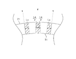
- FIG. 4 shows the magnet unit 22 developed linearly in the circumferential direction.
- the axis of easy magnetization of the magnet 31 approaches the direction perpendicular to the circumferential direction, so the coefficient of linear expansion of the magnet 31 in the circumferential direction is ⁇ v ( ⁇ 0).
- the axis of easy magnetization of the magnet 31 approaches the circumferential direction, so the coefficient of linear expansion of the magnet 31 in the circumferential direction is ⁇ p (>0).
- the amount of dimensional reduction in the circumferential direction when the temperature rises by a unit temperature is defined as Fd.
- Fq is the dimensional increase in the circumferential direction when the temperature rises by the above unit temperature.
- the direction of the easy axis of magnetization on the d-axis side is closer to the direction of the d-axis side than the direction of the easy axis of magnetization on the q-axis side, and
- the magnet 31 is oriented so as to satisfy As a result, it is possible to appropriately suppress the circumferential dimensional change of the magnet 31 due to the temperature change while increasing the torque of the rotary electric machine 10 by realizing an orientation that concentrates the magnet magnetic flux on the d-axis.
- is, for example, desirably 0.9 or more and less than 1, and more desirably 0.95 or more and less than 1.
- the q-axis portion of the magnet 31 is, for example, a portion from the q-axis section of the magnet 31 to a specific position toward the d-axis in the circumferential direction. is a portion up to a specified length La in .
- the specified length La is, for example, 1/8 to 1/4 of the circumferential length of the magnet 31 at the center position in the radial direction.
- Fq is, for example, the amount of change in the circumferential length at the radial center position of the q-axis portion of the magnet 31, or the average value of the amount of change in the circumferential length at each of a plurality of radial positions on the q-axis portion. .
- the d-axis portion of the magnet 31 is, for example, a portion of the magnet 31 that straddles the d-axis, and extends from the d-axis toward one split surface in the circumferential direction to La / 2, and a portion from the d-axis to La/2 toward the other split surface in the circumferential direction.
- Fd is, for example, the amount of change in the circumferential length at the center position in the radial direction of the d-axis portion of the magnet 31, or the average value of the amount of change in the circumferential length at each of a plurality of positions in the d-axis portion.
- the rotor 20 has a q-axis side protrusion 33 that protrudes radially inward from a portion of the rotor carrier 21 that straddles the q-axis.
- the q-axis side projecting portion 33 abuts on a split surface provided on the q-axis side of the magnet 31, and is used, for example, for positioning the magnet 31 in the circumferential direction.
- FIG. 6 shows an example in which the dimension of the q-axis side projecting portion 33 and the dimension of the magnet 31 are the same in the radial direction.
- FIG. 6 shows the magnet unit 22 developed linearly in the circumferential direction.
- the magnet 31 the same one as in the first embodiment can be used.
- the q-axis side protrusion 33 is made of a soft magnetic material such as cast iron, and the linear expansion coefficient ⁇ of the q-axis side protrusion 33 is a positive value in any direction. Therefore, in the q-axis side protrusion 33, the higher the temperature, the larger the circumferential dimension of the q-axis side protrusion 33, and the lower the temperature, the smaller the circumferential dimension of the q-axis side protrusion 33.
- the magnets 31 adjacent in the circumferential direction are arranged with the q-axis side projecting portion 33 interposed therebetween.
- the magnet 31 and the q-axis side protrusion 33 change in dimension in the circumferential direction due to a change in the temperature of the magnet 31 and the q-axis side protrusion 33, The thermal stress tends to increase in either the pressing direction or the direction in which the magnet 31 and the q-axis protrusion 33 move away from each other.
- the q-axis side protrusion 33 may be integrated with the rotor carrier 21 or may be a separate member from the rotor carrier 21 .
- the magnet 31 has a split surface on the d-axis side.
- FIG. 7 shows the magnet unit 22 developed linearly in the circumferential direction.
- the rotor 20 has a d-axis protruding portion 34 that protrudes radially inward from a portion of the rotor carrier 21 that straddles the d-axis.
- the d-axis protruding portion 34 abuts on a split surface provided on the d-axis side of the magnet 31 and is used for positioning the magnet 31 in the circumferential direction.
- FIG. 7 shows an example in which the dimension of the d-axis side projecting portion 34 and the dimension of the magnet 31 are the same in the radial direction.
- the linear expansion coefficient ⁇ of the d-axis side protrusion 34 is a positive value in any direction. Therefore, in the d-axis side projection 34, the higher the temperature, the larger the circumferential dimension of the d-axis side projection 34, and the lower the temperature, the smaller the circumferential dimension of the d-axis side projection 34.
- the d-axis protruding portion 34 is made of, for example, a soft magnetic material such as cast iron or a non-magnetic material such as synthetic resin. As the magnet 31, the same one as in the first embodiment can be used.
- the magnets 31 that are adjacent in the circumferential direction are arranged with the d-axis side projecting portion 34 interposed therebetween.
- the dimension of the d-axis side magnet 31 decreases and the dimension of the d-axis side protrusion 34 increases in the circumferential direction.
- the dimension of the d-axis side magnet 31 increases and the dimension of the d-axis side protrusion 34 decreases in the circumferential direction.
- the fourth embodiment will be described below with reference to the drawings, focusing on differences from the first embodiment.
- the rotary electric machine of the present embodiment is an IPM motor with an inner rotor structure (inner rotation structure).
- FIG. 8 shows a partial cross-sectional view of the rotor 120 that constitutes the rotating electric machine.
- the rotor 120 has a rotor core 121 (corresponding to a "field core") fixed to a rotating shaft (not shown).
- a plurality of magnet housing holes 122 arranged in the circumferential direction are formed in the rotor core 121 , and a magnet 123 (permanent magnet) is embedded in each magnet housing hole 122 .
- the rotor core 121 is formed with a pair of arcuate (arched) magnet housing holes 122 .
- the pair of magnet housing holes 122 are formed in a substantially V shape so that the distance between them increases toward the outer peripheral side, and the pair of magnet housing holes 122 are symmetrical with respect to the d-axis. It's becoming
- the magnet housing hole 122 is formed by being surrounded by arc-shaped curved surfaces 122a and 122b equidistantly spaced from each other and flat connecting surfaces 122c and 122d connecting both ends of the curved surfaces 122a and 122b.
- the connecting surface 122c closer to the q-axis is provided parallel to the q-axis.
- the connecting surface 122d near the d-axis is provided so as to be perpendicular to the d-axis.
- a magnet 123 having the same shape as the hole is inserted into the magnet housing hole 122 .
- one magnetic pole is formed by a pair of magnets 123 housed in a pair of magnet housing holes 122 .
- Magnet 123 has longitudinally opposed sides 123a and 123b, and the easy axis of magnet 123 is indicated by an arrow.
- magnet 123 has an axis of easy magnetization that extends from a direction perpendicular to the q-axis toward the d-axis from the end 123b near the q-axis to the end 123a near the d-axis.
- the direction close to the parallel direction is provided so as to be switched to a convex non-linear shape toward the anti-stator side.
- the magnet magnetic path in the magnet 123 is determined in a direction transverse to the magnet 123 and has an arcuate shape that is convex toward the central axis of the rotor core 121 .
- the axis of easy magnetization of the magnet 123 is in a direction close to the direction perpendicular to the q-axis at the end 123b of the magnet 123 close to the q-axis,
- the end portion 123a close to the d-axis has a direction close to parallel to the d-axis.
- the magnet 123 is a sintered neodymium magnet as in the first embodiment. Further, as in the first embodiment, in the magnet 123, the absolute value of the coefficient of linear expansion in the direction of the axis of easy magnetization is made larger than the absolute value of the coefficient of linear expansion in the direction perpendicular to the axis of easy magnetization.
- Gd the amount of dimensional reduction in the longitudinal direction when the temperature rises by a unit temperature.
- Gq is the dimensional increase in the longitudinal direction when the temperature rises by a unit temperature.
- the direction of the easy axis of magnetization on the d-axis side is closer to the direction of the d-axis side than the direction of the easy axis of magnetization on the q-axis side, and
- the magnets 123 are oriented so as to satisfy As a result, it is possible to achieve an orientation that concentrates the magnetic flux of the magnet on the d-axis, thereby increasing the torque of the rotating electric machine, while suitably suppressing the dimensional change in the longitudinal direction of the magnet 123 due to the temperature change.
- is, for example, desirably 0.9 or more and less than 1, and more desirably 0.95 or more and less than 1.
- the q-axis portion of the magnet 123 is, for example, a portion of the magnet 123 from the q-axis side end 123b to a specific position toward the d-axis side end 123a in the longitudinal direction, It is a portion from the end 123b on the q-axis side to a prescribed length Ga in the longitudinal direction.
- the specified length Ga is, for example, a value of 1/8 to 1/4 of the longitudinal length of the magnet 123 at the center position in the radial direction.
- Gq is, for example, the amount of change in the circumferential length at the radial center position of the q-axis portion of the magnet 123, or the average value of the amount of change in the circumferential length at each of a plurality of radial positions on the q-axis portion. .
- the d-axis portion of the magnet 123 is, for example, a portion of the magnet 123 from the d-axis side end 123a to a specific position toward the q-axis side end 123b in the longitudinal direction, This is the portion from the end 123a on the d-axis side to the specified length Ga in the longitudinal direction.
- Gd is, for example, the amount of change in the circumferential length at the radial center position of the d-axis portion of the magnet 123, or the average value of the amount of change in the circumferential length at each of a plurality of radial positions on the d-axis portion. .
- the cross sections (cross sections perpendicular to the axial direction) of the magnet housing holes 144 formed in the rotor core 121 and the magnets 143 housed therein are rectangular rather than arcuate. It has become.
- the magnet housing hole 144 is formed by being surrounded by flat surfaces 144a and 144b equidistantly spaced from each other and connecting surfaces 144c and 144b connecting the pole positions of the flat surfaces 144a and 144b to each other.
- the magnet housing holes 144 are rectangular with long sides extending from the d-axis side to the q-axis side.
- a pair of left and right magnet housing holes 144 and magnets 143 are arranged in a V shape with the d-axis interposed therebetween.
- the axis of easy magnetization at a position near the end on the d-axis side is made different from the axis of easy magnetization at a position near the end on the q-axis side. That is, in the magnet 143, the magnetization direction is made different between the portion closer to the d-axis and the portion closer to the q-axis. In this case, in the magnet 143, the axis of easy magnetization at the position closer to the end on the d-axis side is closer to parallel to the d-axis than the axis of easy magnetization at the position closer to the end on the q-axis side.
- the magnet 31 may be composed of a plurality of magnets 31a divided in the axial direction. That is, the magnet 31 may be configured by a laminate of a plurality of magnets 31a.
- the magnet 31a has a pair of parallel flat surfaces facing each other in the axial direction.
- the laminated body of the plurality of magnets 31a is integrated by fixing with an adhesive agent or the like in a state where the flat surfaces adjacent to each other in the axial direction are in contact with each other. In this case, the thermal stress between split magnets adjacent to each other in the axial direction tends to increase in the circumferential direction.
- the magnet 31 used has a positive coefficient of linear expansion ⁇ p in the direction of the axis of easy magnetization and a negative coefficient of linear expansion ⁇ v in the direction perpendicular to the axis of easy magnetization.
- the magnet 31 has a positive linear expansion coefficient ⁇ p in the direction of the axis of easy magnetization and a coefficient of linear expansion ⁇ v in the direction perpendicular to the axis of easy magnetization, and the absolute value of the coefficient of linear expansion ⁇ v in the direction perpendicular to the axis of easy magnetization is and the absolute value of the linear expansion coefficient ⁇ p in the direction of the axis of easy magnetization may be different.
- Such magnets include, for example, samarium-cobalt magnets or ferrite magnets. Even in this case, it is possible to suppress the change in the dimension of the magnet 31 in the circumferential direction.
- the dimensions of the q-axis side protrusion 33 and the dimensions of the d-axis side protrusion 34 are set to be the same as the dimensions of the magnet 31 in the radial direction, the present invention is not limited to this.
- the dimension of the q-axis side protrusion 33 and the dimension of the d-axis side protrusion 34 may be smaller than the dimension of the magnet 31 in the radial direction.
- the magnet may be, for example, a magnet 35 having a cleft along the d-axis as shown in FIG. 12, or a cleft along the d-axis in addition to the q-axis as shown in FIG.
- a holding magnet 36 may be used.
- the magnet 36 shown in FIG. 13 constitutes one magnetic pole with two magnets 36a and 36b arranged in the circumferential direction.
- the magnet 35 has a cleft surface along the d-axis as shown in FIG. It is a portion, and is a portion from the split surface of the d-axis to the specified length La in the circumferential direction.
- Fd is, for example, the amount of change in circumferential length at the radial center position in the d-axis portion of the magnet 35, or the average value of the amount of change in circumferential length at each of a plurality of radial positions in the q-axis portion. .
- the q-axis portion of the magnet 35 is, for example, a portion of the magnet 35 that straddles the q-axis, and in the circumferential direction from the q-axis It consists of a portion up to La/2 toward one split plane and a portion up to La/2 toward the other split plane in the circumferential direction from the q-axis.
- Fq is, for example, the amount of change in the circumferential length at the radial center position of the q-axis portion of the magnet 35, or the average value of the amount of change in the circumferential length at each of a plurality of radial positions on the q-axis portion. .
- the q-axis portion of the magnet 36a is, for example, a portion of the magnet 36a extending from the q-axis section to the d-axis in the circumferential direction. This is the portion from the split surface to La/2 in the circumferential direction.
- Fq is, for example, the amount of change in circumferential length at the radial center position of the q-axis portion of the magnet 36a, or the average value of the amount of change in circumferential length at each of a plurality of radial positions on the q-axis portion. .
- the d-axis portion of the magnet 36a is, for example, a portion of the magnet 36a extending from the d-axis cleft to the q-axis in the circumferential direction. This is the portion from the split surface to La/2 in the circumferential direction.
- Fd is, for example, the amount of change in circumferential length at the radial center position of the d-axis portion of the magnet 36a, or the average value of the amount of change in circumferential length at each of a plurality of radial positions on the d-axis portion. .
- the division positions of the magnet in the circumferential direction are not limited to the positions shown in FIGS.
- the number of divisions in the magnet in the circumferential direction can be increased within the range in which the magnet can be manufactured.
- the magnets are not limited to those divided in the circumferential direction, and ring-shaped magnets may be used.
- the rotating electrical machine is not limited to a slotless structure, and may be equipped with teeth.
- the field element is not limited to the rotating electric machine in which the rotor is the rotor, and the rotating electric machine in which the armature is the rotor may be used.
- the disclosure in this specification is not limited to the illustrated embodiments.
- the disclosure encompasses the illustrated embodiments and variations thereon by those skilled in the art.
- the disclosure is not limited to the combinations of parts and/or elements shown in the embodiments.
- the disclosure can be implemented in various combinations.
- the disclosure can have additional parts that can be added to the embodiments.
- the disclosure encompasses omitting parts and/or elements of the embodiments.
- the disclosure encompasses permutations or combinations of parts and/or elements between one embodiment and another.
- the disclosed technical scope is not limited to the description of the embodiments.
- the disclosed technical scope is indicated by the description of the claims, and should be understood to include all modifications within the meaning and range of equivalents to the description of the claims.
Landscapes
- Engineering & Computer Science (AREA)
- Power Engineering (AREA)
- Permanent Field Magnets Of Synchronous Machinery (AREA)
Priority Applications (4)
| Application Number | Priority Date | Filing Date | Title |
|---|---|---|---|
| JP2023503773A JP7424539B2 (ja) | 2021-03-01 | 2022-02-24 | 界磁子 |
| DE112022001319.2T DE112022001319T5 (de) | 2021-03-01 | 2022-02-24 | Feldmagnet |
| CN202280017503.2A CN116941160A (zh) | 2021-03-01 | 2022-02-24 | 励磁子 |
| US18/458,623 US12456891B2 (en) | 2021-03-01 | 2023-08-30 | Field magneton |
Applications Claiming Priority (2)
| Application Number | Priority Date | Filing Date | Title |
|---|---|---|---|
| JP2021-032025 | 2021-03-01 | ||
| JP2021032025 | 2021-03-01 |
Related Child Applications (1)
| Application Number | Title | Priority Date | Filing Date |
|---|---|---|---|
| US18/458,623 Continuation US12456891B2 (en) | 2021-03-01 | 2023-08-30 | Field magneton |
Publications (1)
| Publication Number | Publication Date |
|---|---|
| WO2022186058A1 true WO2022186058A1 (ja) | 2022-09-09 |
Family
ID=83155074
Family Applications (1)
| Application Number | Title | Priority Date | Filing Date |
|---|---|---|---|
| PCT/JP2022/007723 Ceased WO2022186058A1 (ja) | 2021-03-01 | 2022-02-24 | 界磁子 |
Country Status (5)
| Country | Link |
|---|---|
| US (1) | US12456891B2 (https=) |
| JP (1) | JP7424539B2 (https=) |
| CN (1) | CN116941160A (https=) |
| DE (1) | DE112022001319T5 (https=) |
| WO (1) | WO2022186058A1 (https=) |
Families Citing this family (2)
| Publication number | Priority date | Publication date | Assignee | Title |
|---|---|---|---|---|
| WO2025242293A1 (de) * | 2024-05-21 | 2025-11-27 | Pierburg Gmbh | Rotoranordnung für einen axialflussmotor und axialflussmotor mit einer rotoranordnung |
| WO2026078806A1 (ja) * | 2024-10-09 | 2026-04-16 | 三菱電機株式会社 | 直動回転アクチュエータに用いられる永久磁石 |
Citations (5)
| Publication number | Priority date | Publication date | Assignee | Title |
|---|---|---|---|---|
| JP2007068270A (ja) * | 2005-08-29 | 2007-03-15 | Aisin Seiki Co Ltd | モータ用部品 |
| JP2007150194A (ja) * | 2005-11-30 | 2007-06-14 | Aisin Seiki Co Ltd | 永久磁石の固定構造及び固定方法 |
| JP2013106499A (ja) * | 2011-11-16 | 2013-05-30 | Aisin Seiki Co Ltd | 回転電機および回転電機のロータ |
| JP2019122225A (ja) * | 2017-12-28 | 2019-07-22 | 株式会社デンソー | 回転電機 |
| JP2019122232A (ja) * | 2017-12-28 | 2019-07-22 | 株式会社デンソー | 回転電機 |
Family Cites Families (7)
| Publication number | Priority date | Publication date | Assignee | Title |
|---|---|---|---|---|
| JP5731338B2 (ja) | 2011-09-20 | 2015-06-10 | 株式会社日本自動車部品総合研究所 | 回転電機 |
| US11843334B2 (en) | 2017-07-13 | 2023-12-12 | Denso Corporation | Rotating electrical machine |
| CN113991958A (zh) | 2017-07-21 | 2022-01-28 | 株式会社电装 | 旋转电机 |
| JP2019024293A (ja) | 2017-07-21 | 2019-02-14 | 株式会社デンソー | 回転電機 |
| JP7006541B2 (ja) | 2017-12-28 | 2022-01-24 | 株式会社デンソー | 回転電機 |
| DE112018006699T5 (de) | 2017-12-28 | 2020-09-10 | Denso Corporation | Rotierende elektrische Maschine |
| CN111512519B (zh) * | 2017-12-28 | 2022-10-11 | 株式会社电装 | 旋转电机 |
-
2022
- 2022-02-24 CN CN202280017503.2A patent/CN116941160A/zh active Pending
- 2022-02-24 JP JP2023503773A patent/JP7424539B2/ja active Active
- 2022-02-24 DE DE112022001319.2T patent/DE112022001319T5/de active Pending
- 2022-02-24 WO PCT/JP2022/007723 patent/WO2022186058A1/ja not_active Ceased
-
2023
- 2023-08-30 US US18/458,623 patent/US12456891B2/en active Active
Patent Citations (5)
| Publication number | Priority date | Publication date | Assignee | Title |
|---|---|---|---|---|
| JP2007068270A (ja) * | 2005-08-29 | 2007-03-15 | Aisin Seiki Co Ltd | モータ用部品 |
| JP2007150194A (ja) * | 2005-11-30 | 2007-06-14 | Aisin Seiki Co Ltd | 永久磁石の固定構造及び固定方法 |
| JP2013106499A (ja) * | 2011-11-16 | 2013-05-30 | Aisin Seiki Co Ltd | 回転電機および回転電機のロータ |
| JP2019122225A (ja) * | 2017-12-28 | 2019-07-22 | 株式会社デンソー | 回転電機 |
| JP2019122232A (ja) * | 2017-12-28 | 2019-07-22 | 株式会社デンソー | 回転電機 |
Also Published As
| Publication number | Publication date |
|---|---|
| DE112022001319T5 (de) | 2023-12-21 |
| US12456891B2 (en) | 2025-10-28 |
| JPWO2022186058A1 (https=) | 2022-09-09 |
| CN116941160A (zh) | 2023-10-24 |
| US20230412022A1 (en) | 2023-12-21 |
| JP7424539B2 (ja) | 2024-01-30 |
Similar Documents
| Publication | Publication Date | Title |
|---|---|---|
| JP5268711B2 (ja) | 電動機及び圧縮機及び空気調和機及び電気掃除機 | |
| WO2021235267A1 (ja) | 回転子及び電動機 | |
| JP6055725B2 (ja) | 回転子および回転子を用いたアキシャル型回転電機 | |
| CN103907267B (zh) | 永久磁铁嵌入型电动机的转子、电动机、压缩机和空调机 | |
| US9774223B2 (en) | Permanent magnet synchronous machine | |
| JPWO2015156044A1 (ja) | 永久磁石埋込型回転電機 | |
| CN103326486A (zh) | 转子以及旋转电机 | |
| WO2013114542A1 (ja) | 永久磁石埋込型電動機の回転子、及びこの回転子を備えた電動機、及びこの電動機を備えた圧縮機、及びこの圧縮機を備えた空気調和機 | |
| US12456891B2 (en) | Field magneton | |
| JPWO2017212575A1 (ja) | 永久磁石モータ | |
| US11601024B2 (en) | Rotating electrical machine | |
| CN203896058U (zh) | 永磁式旋转电机及电梯驱动提升机 | |
| JPH0479741A (ja) | 永久磁石回転子 | |
| JP2009118594A (ja) | アキシャルギャップ型モータ | |
| WO2023276514A1 (ja) | 回転子及びその製造方法、並びに電動機 | |
| JP2014195351A (ja) | 永久磁石式回転電機 | |
| JP7259798B2 (ja) | アキシャルギャップモータ | |
| JP6440349B2 (ja) | 回転電機 | |
| JP2005051929A (ja) | 電動機 | |
| WO2016203530A1 (ja) | 永久磁石埋込型電動機及び圧縮機 | |
| JP5793948B2 (ja) | 同期電動機 | |
| JP5750995B2 (ja) | 同期電動機 | |
| JPS6035948A (ja) | 扁平形ブラシレスモ−タ | |
| JP5740250B2 (ja) | 永久磁石式回転電機 | |
| JP2018042381A (ja) | 回転電機ロータ |
Legal Events
| Date | Code | Title | Description |
|---|---|---|---|
| 121 | Ep: the epo has been informed by wipo that ep was designated in this application |
Ref document number: 22763114 Country of ref document: EP Kind code of ref document: A1 |
|
| ENP | Entry into the national phase |
Ref document number: 2023503773 Country of ref document: JP Kind code of ref document: A |
|
| WWE | Wipo information: entry into national phase |
Ref document number: 202280017503.2 Country of ref document: CN |
|
| WWE | Wipo information: entry into national phase |
Ref document number: 112022001319 Country of ref document: DE |
|
| 122 | Ep: pct application non-entry in european phase |
Ref document number: 22763114 Country of ref document: EP Kind code of ref document: A1 |