WO2022185768A1 - 表示装置 - Google Patents
表示装置 Download PDFInfo
- Publication number
- WO2022185768A1 WO2022185768A1 PCT/JP2022/002134 JP2022002134W WO2022185768A1 WO 2022185768 A1 WO2022185768 A1 WO 2022185768A1 JP 2022002134 W JP2022002134 W JP 2022002134W WO 2022185768 A1 WO2022185768 A1 WO 2022185768A1
- Authority
- WO
- WIPO (PCT)
- Prior art keywords
- hood
- display
- case
- connecting portion
- end portion
- Prior art date
- Legal status (The legal status is an assumption and is not a legal conclusion. Google has not performed a legal analysis and makes no representation as to the accuracy of the status listed.)
- Ceased
Links
Images


Classifications
-
- B—PERFORMING OPERATIONS; TRANSPORTING
- B60—VEHICLES IN GENERAL
- B60K—ARRANGEMENT OR MOUNTING OF PROPULSION UNITS OR OF TRANSMISSIONS IN VEHICLES; ARRANGEMENT OR MOUNTING OF PLURAL DIVERSE PRIME-MOVERS IN VEHICLES; AUXILIARY DRIVES FOR VEHICLES; INSTRUMENTATION OR DASHBOARDS FOR VEHICLES; ARRANGEMENTS IN CONNECTION WITH COOLING, AIR INTAKE, GAS EXHAUST OR FUEL SUPPLY OF PROPULSION UNITS IN VEHICLES
- B60K37/00—Dashboards
- B60K37/10—Arrangements for attaching the dashboard to the vehicle
-
- B—PERFORMING OPERATIONS; TRANSPORTING
- B60—VEHICLES IN GENERAL
- B60K—ARRANGEMENT OR MOUNTING OF PROPULSION UNITS OR OF TRANSMISSIONS IN VEHICLES; ARRANGEMENT OR MOUNTING OF PLURAL DIVERSE PRIME-MOVERS IN VEHICLES; AUXILIARY DRIVES FOR VEHICLES; INSTRUMENTATION OR DASHBOARDS FOR VEHICLES; ARRANGEMENTS IN CONNECTION WITH COOLING, AIR INTAKE, GAS EXHAUST OR FUEL SUPPLY OF PROPULSION UNITS IN VEHICLES
- B60K35/00—Instruments specially adapted for vehicles; Arrangement of instruments in or on vehicles
- B60K35/20—Output arrangements, i.e. from vehicle to user, associated with vehicle functions or specially adapted therefor
- B60K35/21—Output arrangements, i.e. from vehicle to user, associated with vehicle functions or specially adapted therefor using visual output, e.g. blinking lights or matrix displays
- B60K35/22—Display screens
-
- B—PERFORMING OPERATIONS; TRANSPORTING
- B60—VEHICLES IN GENERAL
- B60K—ARRANGEMENT OR MOUNTING OF PROPULSION UNITS OR OF TRANSMISSIONS IN VEHICLES; ARRANGEMENT OR MOUNTING OF PLURAL DIVERSE PRIME-MOVERS IN VEHICLES; AUXILIARY DRIVES FOR VEHICLES; INSTRUMENTATION OR DASHBOARDS FOR VEHICLES; ARRANGEMENTS IN CONNECTION WITH COOLING, AIR INTAKE, GAS EXHAUST OR FUEL SUPPLY OF PROPULSION UNITS IN VEHICLES
- B60K35/00—Instruments specially adapted for vehicles; Arrangement of instruments in or on vehicles
- B60K35/50—Instruments characterised by their means of attachment to or integration in the vehicle
-
- B—PERFORMING OPERATIONS; TRANSPORTING
- B60—VEHICLES IN GENERAL
- B60R—VEHICLES, VEHICLE FITTINGS, OR VEHICLE PARTS, NOT OTHERWISE PROVIDED FOR
- B60R11/00—Arrangements for holding or mounting articles, not otherwise provided for
- B60R11/02—Arrangements for holding or mounting articles, not otherwise provided for for radio sets, television sets, telephones, or the like; Arrangement of controls thereof
-
- G—PHYSICS
- G09—EDUCATION; CRYPTOGRAPHY; DISPLAY; ADVERTISING; SEALS
- G09F—DISPLAYING; ADVERTISING; SIGNS; LABELS OR NAME-PLATES; SEALS
- G09F9/00—Indicating arrangements for variable information in which the information is built-up on a support by selection or combination of individual elements
-
- B—PERFORMING OPERATIONS; TRANSPORTING
- B60—VEHICLES IN GENERAL
- B60K—ARRANGEMENT OR MOUNTING OF PROPULSION UNITS OR OF TRANSMISSIONS IN VEHICLES; ARRANGEMENT OR MOUNTING OF PLURAL DIVERSE PRIME-MOVERS IN VEHICLES; AUXILIARY DRIVES FOR VEHICLES; INSTRUMENTATION OR DASHBOARDS FOR VEHICLES; ARRANGEMENTS IN CONNECTION WITH COOLING, AIR INTAKE, GAS EXHAUST OR FUEL SUPPLY OF PROPULSION UNITS IN VEHICLES
- B60K35/00—Instruments specially adapted for vehicles; Arrangement of instruments in or on vehicles
- B60K35/10—Input arrangements, i.e. from user to vehicle, associated with vehicle functions or specially adapted therefor
-
- B—PERFORMING OPERATIONS; TRANSPORTING
- B60—VEHICLES IN GENERAL
- B60K—ARRANGEMENT OR MOUNTING OF PROPULSION UNITS OR OF TRANSMISSIONS IN VEHICLES; ARRANGEMENT OR MOUNTING OF PLURAL DIVERSE PRIME-MOVERS IN VEHICLES; AUXILIARY DRIVES FOR VEHICLES; INSTRUMENTATION OR DASHBOARDS FOR VEHICLES; ARRANGEMENTS IN CONNECTION WITH COOLING, AIR INTAKE, GAS EXHAUST OR FUEL SUPPLY OF PROPULSION UNITS IN VEHICLES
- B60K37/00—Dashboards
- B60K37/20—Dashboard panels
Definitions
- the disclosure in this specification relates to a display device.
- Patent Document 1 discloses a display device that displays an image.
- This display device has a display and a back cover.
- the display has a display surface for displaying images.
- the back cover is provided on the back side of the display.
- This display device is mounted on a vehicle and installed in a state embedded in an instrument panel.
- the back cover is cantilevered by the instrument panel or the like.
- the back cover deforms so that the front end portion of the back cover moves in the vertical direction due to an external force, its own weight, or the like. If stress is concentrated on the display due to such deformation of the back cover, there is concern that the display may become abnormal.
- One object of the present disclosure is to provide a display device capable of suppressing the occurrence of an abnormality in the image display section.
- a display device that has a display surface for displaying an image and is attached to an object to be attached so that the display surface faces the vertical direction, an image display unit having a display surface and a display back surface opposite to the display surface; a display case that covers the back surface of the display and is connected to the mounting target; with The display case is The back of the case facing away from the display surface, a base end of the case extending in the longitudinal direction of the back surface of the case and connected to an object to be attached; a case front end portion provided on the side opposite to the case base end portion in the lateral direction of the case back surface and extending in the longitudinal direction; a case short edge portion extending in the lateral direction and bridging the case base end portion and the case tip portion; a base end connection portion that connects the case base end portion to an attachment target; a short edge connection portion that connects the short edge portion of the case to the mounting target; and
- the short edge connecting portion is a display device provided at a position spaced apart from the
- the short edge connecting portion is provided at a position spaced apart from the case base end portion toward the case tip portion side.
- FIG. 2 is a diagram showing the virtual image display device mounted on a vehicle according to the first embodiment;
- FIG. 2 is a longitudinal sectional view of the image display device;
- FIG. 4 is a diagram showing the configuration of a display unit; The figure which shows the structure around a virtual image display apparatus in a vehicle interior.
- 1 is a perspective view showing the configuration of an image display device;
- FIG. 3 is a cross-sectional view of the image display device, taken along the line VI-VI of FIG. 2;
- FIG. 4 is a longitudinal sectional view of the visor hood; The top view which looked at the image display apparatus from the hood back side.
- FIG. 4 is a diagram for explaining vibration of a display; The top view which looked at the comparative example from the hood back side.
- the figure for demonstrating the stress when an external force is applied to a comparative example The figure for demonstrating the stress when an external force is applied to a comparative example.
- the figure for demonstrating the vibration of a comparative example The top view which looked at the comparative example from the hood back side.
- FIG. 10 is a plan view of the image display device in Modification 1 as seen from the rear side of the hood.
- FIG. 11 is a plan view of the image display device according to Modification 2 as viewed from the rear side of the hood.
- FIG. 11 is a plan view of the image display device according to Modification 3 as viewed from the rear side of the hood;
- FIG. 12 is a plan view of the image display device in Modification 4 as seen from the rear side of the hood.
- FIG. 11 is a plan view of the image display device according to Modification 2 as viewed from the rear side of the hood.
- FIG. 12 is a plan view of the image display device according to Modification 3 as viewed from the rear side of the hood.
- FIG. 4 is a diagram for explaining vibration of a display;
- FIG. 21 is a plan view of the image display device in Modification 9 as seen from the rear side of the hood.
- FIG. 21 is a plan view of the image display device according to Modification 10 as viewed from the rear side of the hood.
- FIG. 21 is a plan view of the image display device in Modification 11 as seen from the rear side of the hood.
- FIG. 2 is a diagram showing the arrangement of display units in an image display device;
- FIG. 2 is a diagram showing the arrangement of displays in an image display device;
- FIG. 2 is a block diagram showing the electrical configuration of the image display device;
- FIG. 4 is a diagram for explaining an image displayed on a display surface;
- FIG. 4 is a diagram for explaining a virtual image displayed by a reflective surface;
- FIG. 5 is a diagram for explaining an image displayed on a display surface in a comparative example; The figure for demonstrating the virtual image displayed by the reflective surface in a comparative example.
- FIG. 44 is a cross-sectional view along the XLV-XLV line. Cross-sectional view around the display overlapping portion.
- FIG. 21 is a cross-sectional view of the periphery of the display overlapping portion in Modification 13 of the tenth embodiment;
- An image display device 10 shown in FIG. 1 is mounted on a vehicle 100 .
- the image display device 10 is provided on an instrument panel 102 in a state of being exposed to the cabin 101 of the vehicle 100 .
- the instrument panel 102 is an instrument panel and is provided in front of a seat such as a driver's seat.
- the instrument panel 102 is an interior panel that forms the interior of the passenger compartment 101 .
- the interior panel forms a finished surface that is finished in the passenger compartment 101 .
- a steering wheel 105 is provided between the driver's seat and the instrument panel 102 .
- a front windshield 106 is located above the instrument panel 102 .
- the front of the seat is the front of vehicle 100 . Windshields of the vehicle 100 include the front windshield 106 as well as side windshields.
- the image display device 10 displays various information as an image V.
- the image display device 10 corresponds to a display device.
- Various information includes, for example, vehicle information and travel information.
- the vehicle information is information that indicates the amount of power stored in the vehicle-mounted battery
- the travel information is information that indicates the travel speed, travel mode, travel distance, and the like of the vehicle 100 .
- the various information includes navigation information, entertainment information, air conditioning information, camera information, and the like.
- the navigation information is information indicating the current value of the vehicle 100, information guiding a route from the current location to the destination, and the like.
- Camera information is information captured by an imaging device such as a camera.
- the camera information includes information obtained by imaging the surroundings of the vehicle 100 such as the rear of the vehicle 100 .
- the image display device 10 has a display surface 22 on which an image V can be displayed.
- the display surface 22 displays the image V by outputting image light.
- the image display device 10 has a hood rear surface 52 in addition to the display surface 22 .
- the image display device 10 is formed in a plate shape as a whole.
- the hood back surface 52 faces the side opposite to the display surface 22 in the device thickness direction.
- the device thickness direction is the thickness direction of the image display device 10, and is the direction extending vertically in the present embodiment.
- the device thickness direction is a direction orthogonal to the display surface 22 .
- the image display device 10 is included in the virtual image display device 11 together with the reflecting mirror 15 .
- the virtual image display device 11 is mounted on the vehicle 100 and displays the image V as a virtual image Vi.
- the reflecting mirror 15 is a reflecting member that reflects image light, and is sometimes called a reflecting mirror.
- the reflecting mirror 15 has a reflecting surface 16, and the reflecting surface 16 reflects the image light to display the virtual image Vi.
- Reflecting surface 16 is included in one of a pair of plate surfaces of reflecting mirror 15 .
- the reflecting mirror 15 is a member that performs reflection of the image light incident on the reflecting surface 16, out of transmission and reflection.
- the reflecting mirror 15 corresponds to a virtual image display section that displays a virtual image with image light.
- the reflecting mirror 15 is provided on the instrument panel 102 with the reflecting surface 16 exposed to the vehicle interior 101 .
- Reflecting mirror 15 is fixed to instrument panel 102 while being embedded in instrument panel 102 .
- the reflecting surface 16 faces obliquely upward so as to face the seat side. The reflective surface 16 is easily visible for the passenger sitting on the seat.
- the image display device 10 is provided so that the image light from the display surface 22 is reflected by the reflecting surface 16 toward the seat.
- the image display device 10 is provided above the reflecting mirror 15 with the display surface 22 facing downward and the hood rear surface 52 facing upward.
- the display surface 22 and the reflection surface 16 face each other. An occupant sitting on the seat looks as if the virtual image Vi displayed by the image light is behind the reflecting surface 16 .
- the occupant as a viewer does not directly see the display surface 22, but indirectly sees the display surface 22 by visually recognizing the reflection surface 16.
- the reflective surface 16 is the visible surface Sv visually recognized by the passenger. The occupant can visually recognize the virtual image Vi by visually recognizing the reflecting surface 16, which is the viewing surface Sv.
- the instrument panel 102 has a front portion 102a, a back portion 102b and side portions 102c.
- the front portion 102a and the back portion 102b are arranged in the longitudinal direction of the vehicle.
- the vehicle front-rear direction is the front-rear direction for the vehicle 100 .
- the front portion 102 a forms the front end of the instrument panel 102 .
- the inner part 102b forms the inner end of the instrument panel 102.
- the back portion 102b is positioned higher than the front portion 102a.
- Reflecting mirror 15 is arranged between front portion 102a and back portion 102b. The reflecting mirror 15 is bridged between the front portion 102a and the back portion 102b so that the reflecting surface 16 faces obliquely upward.
- the side portions 102 c form each of a pair of side end portions of the instrument panel 102 and are included in the instrument panel 102 .
- the pair of side portions 102c are arranged in the vehicle width direction.
- the vehicle width direction is the width direction of the vehicle 100 and is a direction perpendicular to the vehicle front-rear direction.
- the side portion 102c extends in the longitudinal direction of the vehicle, and straddles the image display device 10 and the reflecting mirror 15 to bridge the front portion 102a and the back portion 102b.
- the image display device 10 protrudes forward from the back portion 102b.
- the image display device 10 is fixed to the back portion 102b.
- the rear end of the image display device 10 is a base end fixed to the rear portion 102b.
- the front end portion of the image display device 10 is a tip portion arranged above the front portion 102a.
- the display surface 22 is inclined with respect to the reflective surface 16 .
- the separation distance between the display surface 22 and the reflection surface 16 increases toward a position closer to the front end of the image display device 10 .
- the display surface 22 extends in the horizontal direction or in a direction slightly inclined with respect to the horizontal direction.
- the image display device 10 is provided between the reflective surface 16 and the front windshield 106 and covers the reflective surface 16 from above.
- the hood back surface 52 faces the front windshield 106 .
- sunlight passes through the front windshield 106 and enters the vehicle compartment 101 , the sunlight easily strikes the hood back surface 52 but hardly strikes the reflecting surface 16 . Since sunlight does not hit the reflecting surface 16, which is the viewing surface Sv, the occupant can easily visually recognize the virtual image Vi on the viewing surface Sv.
- the image display device 10 has a display 20, a heat insulating section 30, a heat radiating section 40, a visor hood 50, and a hood cover 60.
- the display 20, the heat insulation section 30, and the heat radiation section 40 are included in a display unit 70, which will be described later.
- the display 20 has a display surface 22 and a display back surface 24 .
- the display 20 is formed in a plate shape and has a pair of plate surfaces. In the display 20 , one plate surface is the display front surface 21 and the other plate surface is the display rear surface 24 .
- the display front surface 21 has a display surface 22 and a frame surface 23 (see FIG. 3).
- the display surface 22 has a horizontally long rectangular shape.
- the frame surface 23 has a rectangular frame shape and extends along the outer periphery of the display surface 22 .
- the display 20 can emit image light from the display surface 22 . No image light is emitted from the frame surface 23 .
- the display surface 22 is a display area where the image V is displayed, and the frame surface 23 is a non-display area where the image V is not displayed.
- the display 20 corresponds to an image display section, and the display rear surface 24 corresponds to a display rear surface. Display 20 may be referred to as a display.
- the reflecting mirror 15 displays the image V on the display surface 22 as a virtual image Vi, and displays the frame surface 23 as a virtual image V23 (not shown).
- the virtual image Vi of the image V is displayed by image light, while the virtual image V23 of the frame surface 23 is displayed simply by reflecting the frame surface 23 on the reflecting mirror 15 .
- the virtual image Vi that displays the image V is more conspicuous to the occupant than the virtual image V23 that reflects the frame surface 23 .
- the virtual image V23 is displayed so faintly that the occupant can hardly see it.
- the color of the frame surface 23 is a color that makes the virtual image V23 less noticeable.
- the color of the frame surface 23 is black.
- the color of the frame surface 23 may be the same color or a similar color as the color of the display surface 22 in the OFF state in which the display surface 22 does not display the image V.
- the color of the frame surface 23 may be lower than the color of the display surface 22 in the OFF state in at least one of saturation and brightness.
- the color of the frame surface 23 may be the same color as the background among the various information and the background included in the image V, or a similar color.
- the display 20 is a self-luminous display unit.
- the display 20 includes, for example, an organic EL display.
- An organic EL display includes organic light emitting diodes.
- An organic light-emitting diode is sometimes called an OLED, which is an abbreviation for Organic Light-Emitting Diode.
- the display 20 has a plurality of display elements such as organic EL elements. The plurality of display elements are arranged in a matrix along the display surface 22, and each emits light that becomes image light.
- the display 20 is self-luminous, it does not require a backlight as a light source. In the display 20 configured without a backlight in this way, it is possible to display the black portion of the image V by stopping the light emission of the light emitting elements. On the other hand, unlike this embodiment, in a display with a backlight that includes a backlight, it is conceivable that the light of the backlight slightly leaks from the black portion of the image V. FIG. If even a small amount of light from the backlight leaks from a black portion in the image V, the black portion or its surroundings will appear whitish.
- the visor hood 50 accommodates the display 20 , the heat insulating section 30 and the heat radiating section 40 in a state in which the image light on the display surface 22 can be directed toward the reflecting mirror 15 .
- the visor hood 50 is made of a resin material or the like and has a light shielding property.
- the visor hood 50 is formed in a plate shape as a whole.
- the thickness direction of the visor hood 50 is the device thickness direction.
- a visor hood 50 covers the display back surface 24 of the display 20 .
- the visor hood 50 corresponds to a display case and is sometimes called a housing case or a meter hood.
- the visor hood 50 has a hood front surface 51 in addition to a hood rear surface 52 .
- the visor hood 50 is formed in a plate shape as a whole and has a pair of plate surfaces.
- one plate surface is the hood rear surface 52 and the other plate surface is the hood front surface 51 .
- the hood back surface 52 corresponds to the back surface of the display case and the back surface of the case.
- the visor hood 50 has a hood concave portion 53 provided on the hood front surface 51 .
- the hood recess 53 is a recess that is recessed toward the hood rear surface 52 in the hood front surface 51 .
- the hood recessed portion 53 is open toward the side opposite to the hood rear surface 52 .
- the hood concave portion 53 is provided at a position spaced inward from the outer peripheral edge of the hood front surface 51 .
- the hood front surface 51 extends along the outer peripheral edge of the hood concave portion 53 and has a frame shape.
- the hood recess 53 forms a recessed opening 56 in the hood front surface 51 .
- the recessed opening 56 is an opening formed by the open end of the hood recessed portion 53 .
- the inner surface of the hood concave portion 53 includes a concave bottom surface 54 and a concave wall surface 55 .
- the concave bottom surface 54 is the bottom surface of the hood concave portion 53 and faces the side opposite to the hood rear surface 52 in the device thickness direction.
- a concave bottom surface 54 extends along the hood back surface 52 .
- the concave wall surface 55 extends along the outer peripheral edge of the concave opening 56 .
- the concave wall surface 55 spans the outer peripheral edge of the concave bottom surface 54 and the inner peripheral edge of the hood front surface 51 in the device thickness direction.
- the display 20 is housed in the hood concave portion 53 with the display surface 22 facing away from the concave bottom surface 54 .
- the concave bottom surface 54 faces the display back surface 24 and corresponds to the case facing surface.
- a concave bottom surface 54 extends along the display back surface 24 .
- the visor hood 50 covers the display 20 from the display back surface 24 side.
- the visor hood 50 is located between the display 20 and the front windshield 106 and functions as a light blocking plate. Sunlight traveling toward the display 20 through the front windshield 106 is blocked by the visor hood 50 . Therefore, the visor hood 50 prevents the display 20 from receiving direct sunlight.
- the visor hood 50 has a hood distal end portion 57 and a hood proximal end portion 58 .
- the hood distal end portion 57 forms the distal end portion of the image display device 10
- the hood proximal end portion 58 forms the proximal end portion of the image display device 10 .
- the visor hood 50 is fixed to the back portion 102b and protrudes forward from the back portion 102b in an eave shape.
- the visor hood 50 is a member attached to the instrument panel 102 and attached to the instrument panel 102 in the vehicle interior 101 .
- the visor hood 50 is in a state of being cantilevered by the back portion 102b, and is sometimes called an eaves member.
- the visor hood 50 forms the interior of the passenger compartment 101 .
- the hood cover 60 is fixed to the visor hood 50 while covering the concave opening 56 .
- the hood cover 60 has translucency, and is made of, for example, a resin material or a glass material.
- the hood cover 60 is formed in a plate shape and has a pair of plate surfaces.
- One plate surface of the hood cover 60 is a cover front surface 61 and the other plate surface is a cover rear surface 62 .
- Both the cover front surface 61 and the cover back surface 62 extend along the display surface 22 .
- the cover front surface 61 faces away from the display surface 22 .
- the cover back surface 62 faces the display surface 22 side and faces the display surface 22 .
- the hood cover 60 is arranged at a position spaced forward from the display surface 22 .
- the image light emitted from the display surface 22 passes through the hood cover 60 and is irradiated onto the reflecting mirror 15 .
- the radiator 40 radiates the heat of the display 20 to the outside of the visor hood 50 .
- the heat radiating section 40 has a heat radiating plate section 41 and heat radiating fins 44 . Both the radiator plate portion 41 and the radiator fins 44 are made of a metal material or the like, and have thermal conductivity.
- the radiator plate portion 41 extends along the display back surface 24 and is provided between the display back surface 24 and the heat insulation portion 30 .
- the radiator plate portion 41 is a heat transfer material and forms a heat transfer layer.
- the heat dissipation plate portion 41 has a heat dissipation front face 42 and a heat dissipation back face 43 .
- the radiator plate portion 41 is formed in a plate shape and has a pair of plate surfaces. In the radiator plate portion 41 , one plate surface is a heat radiation front surface 42 and the other plate surface is a heat radiation rear surface 43 .
- the heat dissipating front surface 42 overlaps the display back surface 24 , and the heat dissipating back surface 43 faces the concave bottom surface 54 .
- the heat dissipation plate portion 41 and the display 20 are fixed to each other by joining the heat dissipation front face 42 and the display back face 24 with an adhesive or the like.
- the heat radiation fins 44 are thermally connected to the heat radiation plate portion 41 .
- the radiation fins 44 extend from the radiation plate portion 41 toward the outside of the visor hood 50 and correspond to radiation extension portions.
- the radiating fins 44 have a plurality of fin portions and connecting portions that connect these fin portions.
- the radiation fins 44 are exposed outside the visor hood 50 .
- the heat radiation fins 44 extend from the heat radiation plate portion 41 toward the hood front surface 51 in the device thickness direction.
- the radiation fin 44 is provided at a position spaced apart from the hood concave portion 53 toward the hood base end portion 58 side.
- the radiating fins 44 are positioned apart from the display 20 on both the hood base end portion 58 side and the hood rear surface 52 side.
- the radiation fins 44 are covered from above by at least one of the visor hood 50 and the instrument panel 102 .
- at least one of the visor hood 50 and the instrument panel 102 blocks the irradiation of sunlight to the radiation fins 44 .
- the heat radiation fins 44 are detachably connected to the heat radiation plate portion 41 .
- the radiation fins 44 are fixed to the radiation plate portion 41 by fasteners such as screws.
- the connecting portion of the heat radiating fin 44 and the heat radiating plate portion 41 are connected inside the hood recess 53 .
- the heat radiating plate portion 41, the heat radiating fins 44 and the connector form a heat transfer path.
- the heat transfer path of the heat dissipation portion 40 is a heat dissipation path that releases the heat of the display 20 to the outside of the visor hood 50 .
- the heat insulation part 30 restricts the heat of the visor hood 50 from being transmitted from the concave bottom surface 54 to the display 20 .
- the heat insulating portion 30 is sometimes called a heat transfer restricting portion.
- the heat applied to the visor hood 50 is solar heat.
- solar heat is a type of external light that passes through the windshield and irradiates the hood back surface 52 .
- Sunlight is a type of external light that passes through the windshield and irradiates the hood back surface 52 .
- sunlight is a kind of outside light heat.
- the image display device 10 there are two separate heat paths.
- One of the two heat paths is a heat insulation path through which the heat insulation section 30 blocks solar heat, and the other is a release path through which the heat dissipation section 40 releases heat from the display 20 .
- the heat insulation path is on the hood rear surface 52 side, and the heat radiation path is on the hood front surface 51 side.
- the heat-insulating path and the heat-radiating path are on opposite sides of each other in the device thickness direction.
- the heat insulating part 30 is a heat insulating material made of a resin material, a fiber material, or the like, and has heat insulating properties.
- the thermal conductivity of the heat insulating portion 30 is approximately the same as or lower than the thermal conductivity of air, for example.
- As the heat insulating material there are a combination of resin foam or non-woven fabric and a high-performance heat insulating member such as silica airgel, and a flexible vacuum heat insulating member.
- the heat insulation part 30 forms a heat insulation layer.
- the heat insulating property of the heat insulating portion 30 is higher than that of the visor hood 50 .
- the thermal conductivity of the heat insulating portion 30 is difficult to change even if the temperature of the heat insulating portion 30 changes.
- the thermal conductivity of air tends to change as the temperature of the air changes. For this reason, for example, unlike the present embodiment, in the configuration in which the heat insulating layer is formed with air, there is concern that the heat insulating performance of the heat insulating layer may change with changes in the temperature of the heat insulating layer.
- the heat insulation part 30 is an elastic member having elasticity and stretchability, and is elastically deformable.
- the heat insulating portion 30 elastically deforms or flexibly expands and contracts when an external force is applied to the heat insulating portion 30 .
- the heat insulating portion 30 expands and contracts according to the temperature change of the heat insulating portion 30 .
- the heat insulating portion 30 expands as the temperature rises and shrinks as the temperature drops.
- the heat insulating portion 30 may change its flexibility according to the temperature change of the heat insulating portion 30 .
- the heat insulating portion 30 may become more flexible as the temperature rises and less flexible as the temperature drops.
- the heat insulating portion 30 is more likely to linearly expand or deform due to an external force than the visor hood 50 and the radiator plate portion 41 . That is, the coefficient of linear expansion of the heat insulating portion 30 is larger than the coefficient of linear expansion of each of the visor hood 50 and the radiator plate portion 41, or its tensile strength and Young's modulus are low.
- the heat insulating portion 30 extends along the concave bottom surface 54 and is provided between the concave bottom surface 54 and the radiator plate portion 41 .
- the heat insulating portion 30 is formed in a plate shape and has a pair of plate surfaces.
- one plate surface is the heat insulating front surface 31 and the other plate surface is the heat insulating rear surface 32 .
- the heat-insulating front surface 31 is superimposed on the heat-dissipating back surface 43 and is joined to the heat-dissipating back surface 43 with an adhesive or the like.
- the adiabatic front surface 31 faces the display back surface 24 .
- the heat insulating back surface 32 is overlaid on the concave bottom surface 54 and joined to the concave bottom surface 54 by an adhesive or the like.
- the heat insulating portion 30 is fixed to both the radiator plate portion 41 and the visor hood 50 .
- the display 20 is fixed to the concave bottom surface 54 via the radiator plate portion 41 and the heat insulating portion 30 .
- the elastically deformable heat insulating portion 30 is elastically deformed according to the relative displacement of the display 20 and the radiator plate portion 41 with respect to the visor hood 50 .
- the elastic deformation of the heat insulating portion 30 suppresses the relative displacement of the heat radiating plate portion 41 with respect to the visor hood 50 and the increase in the vibration of the heat radiating plate portion 41 and the display 20 .
- the relative displacement of the display 20 and the heat sink portion 41 with respect to the visor hood 50 includes deformation of at least one of the visor hood 50 , the display 20 and the heat sink portion 41 .
- the vibration of the display 20 is also suppressed by vibration damping and back support by preload.
- vibration damping and back support by preload unlike the present embodiment, in a configuration in which there is an air layer instead of the heat insulating portion 30 on the back side of the display 20, there is a concern that the display 20 may easily vibrate without obtaining an additional effect of suppressing vibration. .
- the display 20 is included in a display unit 70, as shown in FIG.
- a display unit 70 is included in the image display device 10 .
- the display unit 70 has a circuit board 71 and a connection cable 72 in addition to the display 20 .
- the circuit board 71 controls the display 20 by controlling light-emitting elements and the like.
- the circuit board 71 is mounted with electronic components and constitutes, for example, a driver circuit.
- the connection cable 72 electrically connects the circuit board 71 and the display 20 and inputs signals from the circuit board 71 to the display 20 .
- the connection cable 72 is a flexible belt-shaped cable, such as a flexible flat cable.
- a plurality of connection cables 72 are arranged along the outer surface of the display 20 .
- the display unit 70 is housed in the visor hood 50. That is, the visor hood 50 accommodates the circuit board 71 and the connection cable 72 in addition to the display 20 .
- the circuit board 71 is provided at a position spaced apart from the display 20 toward the hood base end portion 58 side.
- at least one of the visor hood 50 and the instrument panel 102 blocks the irradiation of sunlight to the circuit board 71 and the connection cable 72 . Note that the circuit board 71 and the connection cable 72 do not have to be accommodated in the visor hood 50 as long as the circuit board 71 and the connection cable 72 are blocked from being irradiated with sunlight.
- a pair of A-pillars 108 are arranged in the vehicle width direction.
- the A-pillar 108 is provided side by side with the front windshield 106 in the vehicle width direction.
- the A pillar 108 corresponds to a pillar and is sometimes called a front pillar.
- the front windshield 106 is in a state of being stretched over a pair of A-pillars 108 in the vehicle width direction.
- the virtual image display device 11 extends in the vehicle width direction.
- the virtual image display device 11 is installed in the vehicle 100 so that the device width direction is the vehicle width direction.
- the device width direction is the width direction of the image display device 10 .
- both the image display device 10 and the reflecting mirror 15 extend in the vehicle width direction.
- the image display device 10 and the reflecting mirror 15 extend in the vehicle width direction at least in front of the driver's seat.
- the visor hood 50 and the hood cover 60 extend in the vehicle width direction.
- the visor hood 50, the hood cover 60, and the reflecting mirror 15 are all in a state of extending over both side ends of the instrument panel 102 in the vehicle width direction.
- a plurality of display units 70 are arranged in the vehicle width direction.
- a plurality of displays 20 and circuit boards 71 are arranged along the concave bottom surface 54 in the vehicle width direction.
- a plurality of display surfaces 22 are arranged in the vehicle width direction.
- the virtual images Vi displayed by the respective display surfaces 22 are arranged side by side in the vehicle width direction on the reflecting mirror 15 .
- the plurality of virtual images Vi are arranged side by side so as to extend over both side ends of the instrument panel 102 in the vehicle width direction.
- the display unit 70 includes a heat insulating section 30 and a heat radiating section 40 .
- the ends of the display 20, the heat insulating portion 30, and the heat sink portion 41 in the vehicle width direction are arranged in the device thickness direction.
- a plurality of the display 20 , the heat insulation portion 30 and the heat radiation plate portion 41 are arranged along the concave bottom surface 54 in the width direction of the vehicle.
- a plurality of display units 70 are individually fixed to the concave bottom surface 54 . Therefore, each of the plurality of display units 70 can be individually attached to and detached from the visor hood 50 .
- a plurality of display front surfaces 21 are arranged in the width direction of the device.
- the plurality of display front surfaces 21 all face the reflective surface 16 .
- the respective display surfaces 22 and frame surfaces 23 both face the reflective surface 16 .
- the respective frame surfaces 23 have the same color or a similar color. All the colors of these frame surfaces 23 are black, for example, and have the same saturation and brightness. At least one of hue, saturation, and lightness may differ between the plurality of frame surfaces 23, but the smaller the difference, the better.
- a plurality of display surfaces 22 and a plurality of frame surfaces 23 are provided, while a reflecting surface 16 and a cover front surface 61 are provided one each.
- a plurality of virtual images Vi generated from a plurality of images V are collectively displayed on one reflecting surface 16 .
- the virtual image Vi that reflects the image V is more conspicuous than the virtual image V23 that reflects the frame surface 23. FIG. For this reason, it is easier for the passenger to visually recognize the plurality of virtual images Vi in an integrated state rather than in a state of being partitioned by the frame surface 23 .
- the multiple displays 20 are provided at positions that do not block the image light emitted from each. Among the two displays 20 adjacent to each other, one display 20 is provided at a position that does not block the image light emitted from the other display 20 .
- the respective thickness dimensions of the respective displays 20, heat insulating portions 30, and heat radiating plate portions 41 are uniform and substantially the same.
- the respective display surfaces 22, heat-insulating front surfaces 31, and heat-radiating front surfaces 42 are all arranged side by side in the vehicle width direction.
- the distances between the respective display surfaces 22 and the reflecting mirrors 15 are uniform and substantially the same.
- the two adjacent display units 70 are separated from each other.
- the respective displays 20, heat insulating portions 30, and radiator plate portions 41 are separated from each other.
- the gap between the displays 20, the gap between the heat insulating portions 30, and the gap between the heat sink portions 41 are arranged in the device thickness direction.
- Each of the display 20, the heat insulating portion 30, and the heat sink portion 41 has a pair of side end portions aligned in the device width direction.
- the side edges of the display 20, the heat insulating portion 30, and the heat sink portion 41 are arranged in the device thickness direction.
- a plurality of displays 20 and display surfaces 22 are arranged in the device width direction.
- directions orthogonal to each other are referred to as X direction, Y direction, and Z direction, with the X direction being the width direction of the device and the Z direction being the thickness direction of the device.
- the Z direction is the device depth direction.
- the device depth direction is the depth direction of the image display device 10 .
- the X direction is the width direction of the vehicle
- the Z direction is the vertical direction
- the Y direction is the longitudinal direction of the vehicle. 5 and 6, illustration of the heat insulating portion 30, the radiator plate portion 41, and the hood cover 60 is omitted.
- the image display device 10 is attached to an instrument panel 102 as an attachment target.
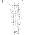
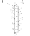
- the visor hood 50 has a hood body 120 and connecting portions 111-113.
- the visor hood 50 is connected to the instrument panel 102 by connecting portions 111-113.
- the hood body 120 forms a main part of the visor hood 50 and has a horizontally long plate shape as a whole.
- the hood body 120 forms a hood front surface 51 , a hood rear surface 52 , a hood concave portion 53 , a hood front end portion 57 , a hood base end portion 58 and a hood side end portion 59 .
- the hood distal end portion 57 and the hood proximal end portion 58 extend in the X direction as a whole.
- the hood side end portion 59 forms a side end portion of the image display device 10 .
- a pair of hood-side end portions 59 are included in the visor hood 50 .
- the pair of hood-side end portions 59 are arranged in the X direction.
- the hood side end portion 59 extends in the Y direction and connects the hood front end portion 57 and the hood base end portion 58 .
- the hood side end portion 59 is shorter than the hood front end portion 57 and the hood base end portion 58 and corresponds to the short edge of the case.
- the hood tip 57 and hood base 58 are sometimes referred to as case long edges.
- the hood front end portion 57 corresponds to the case front end portion
- the hood base end portion 58 corresponds to the case base end portion.
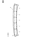
- the visor hood 50 as a whole has a curved shape that expands toward the hood tip portion 57 side.
- the hood distal end portion 57 is curved so as to be recessed toward the hood base end portion 58 side, for example, curved.
- the hood tip 57 has a tip apex 57a.
- the tip top portion 57a is located at the most recessed position toward the hood base end portion 58 side in the hood tip portion 57 .
- the tip top portion 57a is located at an intermediate position between the pair of hood side end portions 59 in the hood tip portion 57. As shown in FIG.
- the hood base end portion 58 is curved, for example curved, so as to swell toward the side opposite to the hood front end portion 57 .
- the hood proximal portion 58 has a proximal top portion 58a.
- the base end top portion 58 a is located at a position where the hood base end portion 58 protrudes most toward the side opposite to the hood tip end portion 57 .
- the base end top portion 58 a is located at an intermediate position between the pair of hood side end portions 59 at the hood base end portion 58 .
- a hood horizontal line L1a of the visor hood 50 extends in the X direction as a whole.
- a hood horizontal line L1a is an imaginary center line that passes through the center of the visor hood 50 and extends in the longitudinal direction of the visor hood 50.
- the hood horizontal line L1a curves toward the hood base end portion 58 so as to swell in the Y direction.
- the hood horizontal line L1a extends in the X direction so as to span the pair of hood-side end portions 59, and corresponds to a longitudinal bending line.
- the hood horizontal line L1a is curved along both the hood distal end portion 57 and the hood proximal end portion 58, for example, curved.
- the hood horizontal line L1a passes through the side end center C1 of the hood side end portion 59 .
- the side end center C ⁇ b>1 is located at an intermediate position between the hood front end portion 57 and the hood base end portion 58 at the hood side end portion 59 .
- the longitudinal direction is the X direction
- the lateral direction is the Y direction.
- a hood vertical line L1b of the visor hood 50 extends linearly in the Y direction along the hood side end portion 59 .
- a hood vertical line L1b is an imaginary center line that passes through the center of the visor hood 50 and extends in the lateral direction of the visor hood 50 , and is located at an intermediate position between the pair of hood base ends 58 .
- the hood front end portion 57 has a front end top portion 57a at a position through which the hood vertical line L1b passes.
- the hood base end portion 58 has a base end top portion 58a at a position through which the hood vertical line L1b passes.
- the hood body 120 has a body base portion 121 and a body frame portion 122 .
- the main body base portion 121 is formed in a plate shape, and the main body frame portion 122 is formed in a frame shape.
- the main body base portion 121 and the main body frame portion 122 are arranged side by side in a direction perpendicular to the Z direction.
- the main body frame portion 122 protrudes from the main body base portion 121 toward the hood front surface 51 , thereby forming a hood concave portion 53 .
- a concave bottom surface 54 is formed by the main body base portion 121 and a concave wall surface 55 is formed by the main body frame portion 122 .
- the thickness dimension of the body frame portion 122 is larger than the thickness dimension of the body base portion 121 . That is, the body frame portion 122 is thicker than the body base portion 121 .
- the hood back surface 52 is formed by the body base portion 121 .
- a hood front surface 51 , a hood front end portion 57 , a hood base end portion 58 and a hood side end portion 59 are formed by the body frame portion 122 .
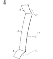
- the visor hood 50 is curved in the Z direction so as to bulge upward so that the upper end is between a pair of hood side end portions 59, for example, curved. .
- the main body base portion 121 of the visor hood 50 is curved in the Z direction so as to expand upward.
- the main body base portion 121 is curved so as to protrude upward, and has an arch shape or a circular arc shape.
- the curvature of the body base portion 121 is uniform in the X direction.
- the arch of the main body base portion 121 is gentle.
- the curvature radius of the main body base portion 121 is larger than the length dimension of the main body base portion 121 in the X direction, for example.
- the hood horizontal line L1a passes through the center of the main body base portion 121 and extends in the X direction.
- the hood horizontal line L1a is curved in the Z direction so as to expand upward, for example, curved.
- the curvature of the hood horizontal line L1a is uniform in the X direction.
- the curvature radius of the hood horizontal line L1a is larger than the length dimension of the main body base portion 121 in the X direction, for example.
- Both the hood back surface 52 and the concave bottom surface 54 are curved along the hood horizontal line L1a.
- the hood horizontal line L1a corresponds to an upward bending line.
- a hood vertical line L1c is an imaginary center line extending in the Z direction through the center of the main body base portion 121 and is located at an intermediate position between the pair of hood base end portions 58 .
- the upper end is at the highest position in the Z direction, and the lower end is at the lowest position in the Z direction.
- the upper end portion of the main body base portion 121 includes a distal top portion 57a and a proximal top portion 58a. In the body base portion 121, the distal top portion 57a and the proximal top portion 58a correspond to the upper end portion.
- connecting portions 111 to 113 connect the hood body 120 to the inner portion 102b and the side portion 102c of the instrument panel 102. As shown in FIG. The connecting portions 111 to 113 positionally hold the hood body 120 with respect to the instrument panel 102 .
- the connecting portions 111 to 113 are portions provided with receiving portions for receiving fasteners or engaging portions.
- Each of the connecting portions 111 to 113 has, for example, ear portions projecting laterally from the hood body 120 in a direction orthogonal to the Z direction, and receiving portions provided on the ear portions.
- the fasteners are fasteners such as bolts, and fasten the visor hood 50 and the instrument panel 102 while being inserted into the receiving portions of the connecting portions 111 to 113 .
- the engaging portion is a portion such as a clip provided on the instrument panel 102, and is a protrusion that engages by being pulled into the receiving portion.
- the receiving portion is a hole or recess into which the fastener or engaging portion is inserted, and is arranged, for example, in the center of the ear portion.
- the positions of the connecting portions 111 to 113 are the positions where the visor hood 50 and the instrument panel 102 are connected.
- the connecting portions 111-113 are sometimes referred to as holding fastening portions.
- the connecting parts 111 to 113 are arranged along the outer peripheral edge of the hood body 120 .
- the outer connecting portion 111 and the inner connecting portion 112 connect the hood base end portion 58 to the inner portion 102b and correspond to base end connecting portions.
- a plurality of outer connecting portions 111 and inner connecting portions 112 are arranged along the hood base end portion 58 .
- the outer connecting portion 111 and the inner connecting portion 112 protrude from the hood body 120 toward the side opposite to the hood tip portion 57 .
- the outer connecting portion 111 is provided outside the inner connecting portion 112 in the X direction. That is, the outer connecting portion 111 is provided at a position closer to the hood-side end portion 59 than the inner connecting portion 112 is.
- the outer connecting portion 111 is provided for each of the pair of hood-side end portions 59 .
- the pair of outer connecting portions 111 are arranged along the hood base end portion 58 . Both of the pair of outer connecting portions 111 are positioned apart from the hood side end portion 59 toward the hood vertical line L1b.
- the outer connecting portion 111 is positioned closer to the hood side end portion 59 than the hood vertical line L1b in the X direction.
- the outer connecting portion 111 corresponds to a base connecting portion and is sometimes referred to as a main holding fastening portion.
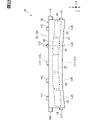
- a plurality of inner connecting portions 112 are provided between a pair of outer connecting portions 111 in the X direction. These inner connecting portions 112 are arranged along the hood base end portion 58 . All of the plurality of inner connecting portions 112 are provided on the opposite side of the hood front end portion 57 from the outer connecting portion 111 in the Y direction. The inner connecting portion 112 is at a position shifted in the Y direction with respect to the outer connecting portion 111 .
- the inner connecting portion 112 corresponds to a displaced connecting portion and is sometimes called a sub-holding fastening portion.
- the plurality of inner connecting portions 112 include an intermediate connecting portion 112a.
- the intermediate connecting portion 112a is the inner connecting portion 112 arranged at a position through which the hood vertical line L1b passes.
- the intermediate connecting portion 112 a is arranged at an intermediate position between the pair of hood side end portions 59 at the hood base end portion 58 .
- the intermediate connecting portion 112 a is located on the side opposite to the hood tip portion 57 most among the plurality of inner connecting portions 112 . Note that even if the intermediate connecting portion 112a is slightly shifted in the X direction from the intermediate position of the pair of hood side end portions 59, it is sufficient that the hood vertical line L1b passes through a portion of the intermediate connecting portion 112a.
- the outer connecting portion 111 is arranged closer to the hood tip portion 57 than the intermediate connecting portion 112a in the Y direction. In the Y direction, the outer connecting portion 111 is positioned closer to the distal top portion 57a than to the proximal top portion 58a. In the Y direction, the distance Db between the outer connecting portion 111 and the tip top portion 57a is smaller than the distance Da between the intermediate connecting portion 112a and the tip top portion 57a.
- the front connecting portion 113 connects the hood side end portion 59 to the side portion 102c.
- One front connecting portion 113 is provided on each of the pair of hood-side end portions 59 .
- the front connecting portion 113 protrudes laterally from the hood-side end portion 59 .
- the front connecting portion 113 corresponds to a short edge connecting portion and is sometimes referred to as left and right end fastening portions.
- the front connecting portion 113 is provided at a position spaced from the hood base end portion 58 toward the hood front end portion 57 at the hood side end portion 59 .
- the front connecting portion 113 is located between the hood tip portion 57 and the hood base end portion 58 and is spaced from both the hood tip portion 57 and the hood base end portion 58 .
- the front connecting portion 113 is located at an intermediate position between the hood distal end portion 57 and the hood proximal end portion 58 at the hood side end portion 59, for example.
- An intermediate position for the front connecting portion 113 is a position where the front connecting portion 113 straddles the side end center C1 in the Y direction.
- This intermediate position is a position where the hood horizontal line L1a passes through a portion of the front connecting portion 113. As shown in FIG. In the Y direction, the front connecting portion 113 is positioned closer to the hood distal end portion 57 than to the hood proximal end portion 58 .
- the positions of the connecting portions 111 to 113 are set at the respective centers.
- the outer connecting portion 111 and the inner connecting portion 112 may protrude outside the hood base end portion 58 in the Y direction, or may be positioned inside the hood base end portion 58. good.
- the front connecting portion 113 may be located outside the hood side end portion 59 in the X direction, or may be located inside the hood side end portion 59 .
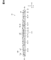
- a plurality of displays 20 are arranged along the hood horizontal line L1a.
- the displays 20 are lined up along both the hood distal end 57 and the hood proximal end 58 .
- the display 20 extends in the direction in which the hood horizontal line L1a extends.
- One of the two adjacent displays 20 is tilted with respect to the other.
- the relative tilt angle of one of the two adjacent displays 20 with respect to the other is the same for each of the multiple sets. For example, all the displays 20 have the same relative tilt angle, for example, 10 degrees each when viewed sequentially from the display 20 at one end in the X direction.
- each horizontal display line L2a extends in the X direction as a whole.
- the display horizontal line L2a extends linearly along the hood horizontal line L1a.
- the display horizontal line L2a is an imaginary center line passing through the center of the display 20 and extending along the long side of the display front surface 21 .
- One display horizontal line L2a of the two adjacent displays 20 is inclined with respect to the other display horizontal line L2a.
- the display vertical line L2b of the display 20 extends linearly in the Y direction, similar to the hood vertical line L1b.
- the display vertical line L2b is an imaginary center line that passes through the center of the display 20 and extends along the short side of the display front surface 21 .
- respective display vertical lines L2b extend parallel to each other.
- the plurality of displays 20 includes a display 20 centered on the visor hood 50 in the Y direction.
- a display vertical line L2b of the display 20 coincides with the hood vertical line L1b.
- the display vertical line L2b corresponds to the display center line.
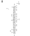
- the base end connecting portions such as the outer connecting portion 111 and the inner connecting portion 112 are individually provided for each of the multiple displays 20 .
- the outer connecting portion 111 and the inner connecting portion 112 are arranged at a position in the hood base end portion 58 through which the display vertical line L2b passes.
- a center line extending in the Y direction through the centers of the outer connection portion 111 and the inner connection portion 112 coincides with the display vertical line L2b.
- one of the outer connecting portion 111 and the inner connecting portion 112 is arranged at a position through which each of the plurality of display vertical lines L2b passes.
- the multiple displays 20 are arranged along the hood horizontal line L1a so that the displays 20 at both ends in the Y direction are arranged at the lowest position.
- the multiple displays 20 are arranged so as to form a shape that bulges upward as a whole. All of these displays 20 are connected to each other through the heat insulating portion 30 , the radiator plate portion 41 and the visor hood 50 . That is, the multiple displays 20 are indirectly connected to each other.
- the plurality of displays 20 are arranged side by side in the image display device 10 .
- a wide display area can be provided by one visor hood 50 on the instrument panel 102, such as enlarging the viewing surface Sv.
- a virtual image Vi displayed by the occupant on the reflecting surface 16 is used instead of a real image method in which the occupant directly visually recognizes the cover front surface 61 and the display surface 22. Therefore, the image V is visually recognized. can enhance sexuality.
- the image display device 10 since the display surface 22 faces downward, it is difficult for external light such as sunlight to directly hit the display surface 22 . Therefore, it is possible to prevent the visibility of the virtual image Vi from deteriorating due to external light.
- the virtual image Vi is displayed at a position farther than the reflecting surface 16 for the occupant, for example, when the driver who has adjusted his eyes to a distant position in front of the vehicle moves his eyes to the virtual image Vi, it is possible for the driver to drive.
- a person can visually recognize the virtual image Vi from a distant viewpoint. Therefore, when a passenger such as a driver visually recognizes the virtual image Vi, the load for adjusting the focus of the eyes can be reduced.
- the virtual image Vi can be displayed as long as the reflecting mirror 15 can be installed. Therefore, the viewing plane Sv for viewing the image V can be more freely set in position.
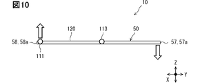
- the front connecting portion 113 is provided at a position spaced apart from the hood base end portion 58 toward the hood tip portion 57 side.
- the front connecting portion 113 can prevent the visor hood 50 from being deformed such that the hood tip portion 57 moves vertically due to an external force or its own weight. Therefore, it is possible to suppress the deformation of the visor hood 50 and the concentration of stress on the display 20 and the occurrence of an abnormality in the display 20 .
- the image display device 10 is arranged in a special manner in which it is laid down at an angle close to horizontal in order to realize the virtual image method.
- the image display device 10 is placed on the instrument panel 102 at an angle close to the vertical in order to realize the real image method. likely to occur.
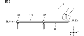
- a bending load is applied to the visor hood 50 when an occupant casually puts his or her hand on the instrument panel 102 .
- a bending load may be applied to the visor hood 50 due to the weight of the display 20 or the like.
- an external force is applied to the visor hood 50 to push down the hood front end portion 57 such as the front end top portion 57a.
- the stress due to the external force is dispersed and transmitted to the outer connecting portion 111, the inner connecting portion 112, and the front connecting portion 113.
- the front connecting portion 113 can prevent the visor hood 50 from bending or deforming so that the hood tip portion 57 moves downward.
- the front connecting portion 113 is closer to the hood tip portion 57 than the outer connecting portion 111 and the inner connecting portion 112 . Therefore, the stress applied to the front connecting portion 113 tends to be greater than the stress applied to the outer connecting portion 111 and the inner connecting portion 112 . Therefore, the front connecting portion 113 can prevent excessively large stress from being applied to the outer connecting portion 111 and the inner connecting portion 112 . Therefore, the front connecting portion 113 can prevent the outer connecting portion 111 and the inner connecting portion 112 from being deformed by the stress.
- a rotational moment is generated in the visor hood 50 due to the external force applied to the hood tip portion 57 .
- the outer connecting portion 111 and the inner connecting portion 112 are affected by the rotational moment.
- a pushing force is generated in the opposite direction. Therefore, even if a rotational moment is generated with respect to the visor hood 50 , the visor hood 50 can be maintained in an appropriate state by the outer connecting portion 111 , the inner connecting portion 112 and the front connecting portion 113 .
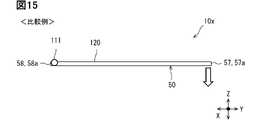
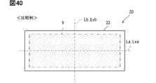
- a comparative example 10x different from the present embodiment is assumed.
- the visor hood 50 does not have the front connecting portion 113 .
- Comparative Example 10x as shown in FIG. 14, when a downward external force is applied to the hood tip portion 57, the stress due to this external force is directly transmitted to the outer connecting portion 111 and the inner connecting portion 112. FIG. Therefore, there is concern that excessively large stress is applied to the outer connecting portion 111 and the inner connecting portion 112 .
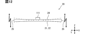
- the visor hood 50 is arranged so that the display surface 22 faces downward.
- the image display device 10 vibrates as the vehicle 100 travels. In the vehicle 100, the vibration in the vertical direction tends to be greater than the vibration in the longitudinal direction of the vehicle and the vibration in the width direction of the vehicle.
- the image display device 10 which is arranged in a lying state with an increased viewing surface Sv and a thinner visor hood 50, is likely to bend or deform due to vibration in the vertical direction.
- the image display device 10 with the display surface 22 facing downward is susceptible to vertical vibrations generated in the vehicle 100 .
- the virtual image method in which both the display surface 22 and the reflection surface 16 vibrate tends to have a greater influence of the vibration on the viewing surface Sv.
- deflection of the visor hood 50 due to vibration, displacement of the display surface 22 due to vibration, and display blur due to resonance tend to increase.
- the front connecting portion 113 is provided between the hood tip portion 57 and the outer connecting portion 111 and the inner connecting portion 112 in the Y direction.
- the front connecting portion 113, the outer connecting portion 111, and the inner connecting portion 112 are considered to be fulcrums of vibration in the Y direction. .
- the front connecting portion 113 not the outer connecting portion 111 and the inner connecting portion 112 becomes the fulcrum of vibration. Therefore, even in the image display device 10 in which the separation distance between the hood front end portion 57 and the hood base end portion 58 is increased as the visor hood 50 is enlarged, the swing width Sw of the hood front end portion 57 can be reduced. Therefore, problems caused by vibration, such as bending of the visor hood 50 and blurring of the display, can be suppressed.
- the visor hood 50 is attached to the instrument panel 102 while the image display device 10 is mounted on the vehicle 100 .
- the visor hood 50 of the vehicle 100 is likely to be vibrated. Therefore, a configuration capable of suppressing problems caused by vibration such as bending of the visor hood 50 and blurring of the display is effective for the image display device 10 mounted on the vehicle 100 from the viewpoint of protecting the display 20 from vibration.
- the outer connecting portion 111 and the inner connecting portion 112 serve as fulcrums of vibration for the hood tip portion 57 .
- the swing width Swx of the hood tip portion 57 is larger than the swing width Sw of the hood tip portion 57 in this embodiment.
- the stress is concentrated on the display 20 due to the bending of the visor hood 50, the display 20 may become abnormal.
- the visor hood 50 is held by the instrument panel 102 below the front windshield 106 .
- the posture of the visor hood 50 may not be stable.
- the cantilever support of the visor hood 50 is eliminated by the front connecting portion 113, the posture of the visor hood 50 can be stabilized.
- the hood distal end portion 57 may be displaced downward and the load on the hood proximal end portion 58 may be amplified.
- the front connecting portion 113 eliminates the visor hood 50 from being supported like a cantilever beam. Therefore, problems such as downward displacement of the hood distal end portion 57 and amplification of the load on the hood proximal end portion 58 can be eliminated.
- the visor hood 50 has the front connecting portion 113 but does not have the outer connecting portion 111 and the inner connecting portion 112 .
- the hood base end portion 58 is not connected to the instrument panel 102
- the pair of hood side end portions 59 are connected to the instrument panel 102 . That is, the visor hood 50 is held at its left and right ends.
- the visor hood 50 will be in a state like a beam supported at both ends, and will be weak against bending and likely to resonate.
- the visor hood 50 is prevented from being like a beam supported at both ends by the outer connecting portion 111 and the inner connecting portion 112 . Therefore, it is possible to prevent the visor hood 50 from becoming weak against bending and from easily resonating.
- the front connecting portion 113 is provided at the hood side end portion 59 at a position spaced apart from the hood distal end portion 57 toward the hood base end portion 58 side. Therefore, for example, when an external force is applied to the hood front end portion 57 , the external force is likely to be dispersed among the front connecting portion 113 , the outer connecting portion 111 and the inner connecting portion 112 .
- the front connecting portion 113 is located at an intermediate position between the hood front end portion 57 and the hood base end portion 58, the external force applied to the hood front end portion 57 is applied to the front connecting portion 113, the outer connecting portion 111, and the inner connecting portion. 112 can be reliably distributed. Therefore, application of an excessively large stress to the front connecting portion 113 can be suppressed.
- the outer connecting portion 111 and the inner connecting portion 112 are arranged along the hood base end portion 58 and provided at positions shifted in the Y direction.
- an external force applied to the tip top portion 57a is easily transmitted to the outer connecting portion 111 or the inner connecting portion 112, whichever is closer to the tip top portion 57a. Therefore, deformation of the visor hood 50 such that the tip top portion 57a moves downward can be suppressed by the outer connection portion 111 and the inner connection portion 112, whichever is closer to the tip top portion 57a.
- the outer connection portion 111 is positioned closer to the tip top portion 57a than the inner connection portion 112 in the Y direction. Can be placed close to each other. Moreover, since the inner connecting portion 112 is arranged between the pair of outer connecting portions 111, each of the pair of outer connecting portions 111 can be arranged at a position closer to the tip top portion 57a than the inner connecting portion 112 in the Y direction. Therefore, for example, when an external force is applied to the tip top portion 57a, the outer connection portion 111 can prevent the visor hood 50 from deforming so that the tip top portion 57a moves in the vertical direction.
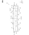
- a comparative example 10y different from the present embodiment is assumed.
- the hood base end portion 58 is not bent in the Y direction, and the positions of the outer connecting portion 111 and the inner connecting portion 112 are not shifted in the Y direction.
- the separation distance Db between the outer connecting portion 111 and the tip top portion 57a is the same as the separation distance Da between the intermediate connecting portion 112a and the tip top portion 57a.
- the outer connecting portion 111 will not provide enough restraining force against the deformation of the visor hood 50 such that the tip top portion 57a moves downward.
- the separation distance Db is smaller than the separation distance Da, the outer connecting portion 111 is prevented from deforming the visor hood 50 such that the tip top portion 57a moves downward. can increase power.
- the outer connecting portion 111 and the inner connecting portion 112 are provided at positions overlapping the display vertical line L2b.
- the outer connecting portion 111 and the inner connecting portion 112 can prevent the display 20 from deforming so that the center of the display 20 moves in the vertical direction.
- the image V displayed by the display 20 it is considered that various information is displayed at a position near the center of the image V, and the background is displayed at a position farther from the center of the image V in many cases. Therefore, the suppression of vertical movement of the center of the display 20 by the outer connecting portion 111 and the inner connecting portion 112 is effective in improving the visibility of the image V and the virtual image Vi.
- the visor hood 50 is bent upward so that the upper end portion is present between the pair of hood side end portions 59 .
- the external force and its own weight applied to the visor hood 50 become a compressive force that compresses the visor hood 50 downward. Therefore, it is possible to suppress deformation of the visor hood 50 so as to bend downward. Therefore, it is possible to suppress deformation of the visor hood 50 such that the hood tip portion 57 and the like move partially downward.
- the visor hood 50 is curved as a whole and has an arch shape, it can reliably exert a compressive force against an external force and its own weight.
- the visor hood 50 has the main body base portion 121 and the main body frame portion 122 .
- the portion of the visor hood 50 where the body frame portion 122 is provided is larger in thickness than the body base portion 121 by the body frame portion 122 . Therefore, the portion of the visor hood 50 that overlaps the display 20 can be made thinner by the main body base portion 121 .
- the portion of the visor hood 50 that does not overlap the display 20 can increase the strength and rigidity of the visor hood 50 by the body frame portion 122 .
- the multiple displays 20 are arranged along the hood horizontal line L1a while being connected to each other via the visor hood 50 . That is, a plurality of displays 20 are arranged in an arch shape.
- the external force and own weight applied to the multiple displays 20 and the visor hood 50 become compressive forces that compress the multiple displays 20 and the visor hood 50 downward. Therefore, deformation of the visor hood 50 can be suppressed by arranging the plurality of displays 20 .
- the arrangement of the displays 20 can prevent the visor hood 50 from deforming such that the hood tip portion 57 and the like partially move downward.
- the horizontal display line L2a in the display 20 becomes a vibration axis that vibrates vertically.
- the multiple displays 20 are arranged so as to be curved in the Y direction along the horizontal hood line L1a. Therefore, for example, when vibration is applied to the image display device 10, the vibration axes of the plurality of displays 20 do not match each other. Therefore, it is possible to suppress resonance of vibrations generated in each of the plurality of displays 20 . In addition, the vibration generated in each of the multiple displays 20 can be easily reduced.
- one display horizontal line L2a of the two adjacent displays 20 is inclined with respect to the other display horizontal line L2a.
- These display horizontal lines L2a do not coincide with each other because they have different inclination angles. For this reason, even if two adjacent displays 20 vibrate with their respective display horizontal lines L2a as vibration axes, the tilt angles of these vibration axes do not match, making it difficult for these displays 20 to resonate.
- a plurality of displays 20 are arranged in an arch shape along the curved hood horizontal line L1a. Therefore, in two adjacent displays 20, one has an inclination angle in each direction of roll, pitch, and yaw with respect to the other. Two adjacent displays 20 are devisedly arranged so that these displays 20 are displaced from one beam. Therefore, it is possible to prevent two adjacent displays 20 from resonating like one beam. In addition, the vibration generated in each of the two adjacent displays 20 can be easily reduced individually.
- the visor hood 50 is curved so as to bulge upward so that the upper end portion is between the pair of hood side end portions 59, so that the external force applied to the visor hood 50 and its own weight are compressed. It becomes easy to act on the visor hood 50 as a force. Therefore, even if an external force is applied to the visor hood 50, the shape of the visor hood 50 can be properly maintained. Therefore, the curved shape of the visor hood 50 can prevent the visor hood 50 from deforming and causing an abnormality in the display 20 .
- the visor hood 50 has a curved arch shape, the external force and its own weight on the visor hood 50 can more reliably act as a compressive force. Therefore, the moment of inertia of the area tends to increase against the pressing load from the hood back surface 52 due to external force, self weight, or the like. Therefore, bending strength such as bending rigidity and bending strength of the visor hood 50 can be increased. By increasing the bending strength of the visor hood 50 in this way, it is possible to reduce the occurrence of vibration and resonance of the visor hood 50 even with respect to vehicle vibration.
- the visor hood 50 may deform such that the vicinity of the center of the visor hood 50 moves downward. In this configuration, there is concern that stress will concentrate on the display 20 as the visor hood 50 deforms, causing an abnormality in the display 20 .
- both the hood back surface 52 and the concave bottom surface 54 are bent upward.
- the visor hood 50 can be curved to expand upward.
- the curvature of the hood back surface 52 and the curvature of the concave bottom surface 54 are the same, the external force and the weight of the visor hood 50 can more reliably act as a compressive force.
- the hood side end portion 59 is connected to the instrument panel 102 as the lower end portion of the visor hood 50 .
- the supporting force with which the instrument panel 102 supports the hood-side end portion 59 resists the compressive force generated in the visor hood 50 , thereby suppressing deformation of the visor hood 50 .
- a plurality of displays 20 are arranged in the X direction along the horizontal hood line L1a while being connected to each other.
- the upwardly curved portion of the image display device 10 can be formed by a plurality of displays 20 . Therefore, the external force and its own weight applied to the visor hood 50 tend to act on the multiple displays 20 as compressive force. Therefore, even if an external force is applied to the visor hood 50 , the shape of the visor hood 50 can be properly maintained by the multiple displays 20 . As a result, it is possible to prevent the visor hood 50 from deforming and causing an abnormality in the display 20 by bending the display 20 and interconnecting the displays 20 .
- the multiple displays 20 are connected to each other via the visor hoods 50 .
- the visor hood 50 in addition to the multiple displays 20 forms an upward curved portion of the image display device 10 . Therefore, the visor hood 50 can be used in addition to the multiple displays 20 as a portion for suppressing deformation of the visor hood 50 .
- one of the two adjacent displays 20 is inclined with respect to the other while being connected to each other. Therefore, in a configuration in which a plurality of displays 20 form an upwardly curved portion of the image display device 10, the plurality of displays 20 can be arranged so as to extend along the curve of this portion. Therefore, the deterrent force against deformation of the visor hood 50 can be enhanced by the orientation of each of the multiple displays 20 .
- the plurality of display surfaces 22 are arranged along the reflecting surface 16 while facing the reflecting surface 16 .
- the image V displayed on each of the multiple display surfaces 22 is displayed as multiple virtual images Vi by the reflecting surface 16 . Therefore, it is possible for the passenger to collectively view the plurality of virtual images Vi on the single reflecting surface 16 . Since the reflecting surface 16 is the viewing surface Sv for the passenger, the viewing surface Sv can be enlarged in the virtual image display device 11 .
- the virtual image Vi displayed by the image light is more conspicuous than the virtual image V23 in which only the frame surface 23 is reflected. Therefore, it is possible to reduce the conspicuousness of the virtual image gap area on one viewing surface Sv that displays a plurality of virtual images Vi.
- the virtual image gap area is an area indicating the gap between adjacent virtual images Vi. Therefore, it is possible to prevent the occupant from having a sense of discomfort in the virtual image gap area when the occupant visually recognizes the viewing surface Sv. In other words, it is possible to enhance the seamlessness of the plurality of virtual images Vi viewed from the viewing surface Sv.
- a self-luminous display unit is used as the display 20
- leakage of backlight from black portions of the image V can be avoided.
- the display front surface 21 leakage of backlight from the boundary between the outer peripheral edge of the display surface 22 and the inner peripheral edge of the frame surface 23 is avoided. Therefore, it is possible to prevent the frame surface 23 from being conspicuous due to the light of the backlight in the virtual image gap area. Therefore, the seamless feeling on the viewing surface Sv can also be enhanced by preventing light leakage from the backlight.
- a plurality of displays 20 are arranged in the device width direction. With this configuration, it is possible to prevent image light emitted from one of the two displays 20 adjacent to each other from being blocked by the other display 20 . Therefore, it is possible to prevent the virtual image gap area from being conspicuous due to the blocking of the image light.
- the frame surfaces 23 of the multiple displays 20 have the same color.
- the virtual image V23 of the frame surface 23 can be made uniform in the degree to which the virtual image V23 of the frame surface 23 is inconspicuous for the plurality of displays 20 . Therefore, when a plurality of virtual images V23 are displayed on the viewing surface Sv of the frame surface 23, it is possible to prevent only some of the virtual images V23 from standing out.
- the visor hood 50 that covers the display back surface 24 is in a state of spanning over the multiple displays 20 . Therefore, the visor hood 50 can prevent the plurality of displays 20 from being displaced. For example, the visor hood 50 can prevent the two adjacent display surfaces 22 from being relatively displaced and the two virtual images Vi displayed by these display surfaces 22 to be displaced.
- the visor hood 50 spans over the pair of A-pillars 108.
- the portion where the visor hood 50 is fixed to the instrument panel 102 can be arranged at a position as close to the A-pillar 108 as possible. Therefore, the support strength of the visor hood 50 by the instrument panel 102 can be increased.
- the visor hood 50 in the vehicle interior 101 can be made as large as possible in the vehicle width direction. Therefore, the number of image display devices 10 accommodated in the visor hood 50 can be increased.
- the viewing surface Sv which is the reflecting surface 16, can be increased in size.
- the visor hood 50 is a member attached to the instrument panel 102 . Therefore, it is possible to prevent the visor hood 50 from degrading the design of the passenger compartment 101 . Therefore, the visor hood 50 can enhance the design of the passenger compartment 101 . In particular, in a configuration in which the visor hood 50 is also enlarged in accordance with an increase in the size of the visible surface Sv, the visor hood 50 tends to stand out in the vehicle interior 101 . Therefore, it is effective to improve the design of the passenger compartment 101 by using the visor hood 50 .
- the hood side end portion 59 is provided with only one front connecting portion 113 as a short edge connecting portion.
- the hood side end portion 59 is provided with a plurality of short edge connecting portions. Configurations, actions, and effects not specifically described in the second embodiment are the same as those in the first embodiment. 2nd Embodiment demonstrates centering on a different point from the said 1st Embodiment.
- the visor hood 50 has a rear connecting portion 114 as a short edge connecting portion in addition to the front connecting portion 113 .
- Both the front connection portion 113 and the rear connection portion 114 are provided on each of the pair of hood side end portions 59 .
- the rear connecting portion 114 is provided between the front connecting portion 113 and the hood base end portion 58 .
- the front connecting portion 113 corresponds to the first connecting portion
- the rear connecting portion 114 corresponds to the second connecting portion.
- the rear connecting portion 114 connects the hood side end portion 59 to the side portion 102c.
- the back connecting portion 114 has the same structure as the connecting portions 111 to 113, such as having an ear portion and a receiving portion.
- One rear connecting portion 114 is provided for each of the pair of hood-side end portions 59 .
- the inner connecting portion 114 protrudes laterally from the hood-side end portion 59 .
- the rear connecting portion 114 corresponds to a short edge connecting portion and is sometimes referred to as left and right end fastening portions. Since the outer connecting portion 111 is separated from the hood side end portion 59 toward the hood vertical line L1b, the inner connecting portion 114 is separated from the outer connecting portion 111 toward the hood side end portion 59 side.
- the back connecting portion 114 is provided on the back side of the front connecting portion 113 at the hood side end portion 59 , and is located at the hood base end portion 58 at the hood side end portion 59 .
- the rear connecting portion 114 extends from the hood base end portion 58 toward the hood front end portion 57 side.
- the inner connecting portion 114 is located at the hood side end portion 59 at a position spaced apart from the side end center C1 toward the hood base end portion 58 side.
- the back connecting portion 114 may be provided at a position spaced apart from the hood base end portion 58 toward the hood front end portion 57 side.
- the back connecting portion 114 may be provided at a position straddling the hood base end portion 58 in the Y direction. In short, the rear connecting portion 114 may be provided closer to the hood base end portion 58 than the front connecting portion 113 at the hood side end portion 59 .
- the front connecting portion 113 is provided closer to the front side than the back connecting portion 114 and is located at the hood tip portion 57 at the hood side end portion 59 .
- the front connecting portion 113 extends from the hood distal end portion 57 toward the hood proximal end portion 58 side.
- the front connecting portion 113 is located at the hood side end portion 59 at a position spaced apart from the side end center C1 toward the hood tip portion 57 side.
- the front connecting portion 113 may be provided at a position spaced apart from the hood distal end portion 57 toward the hood proximal end portion 58 side, as in the first embodiment.
- the front connecting portion 113 may be provided at a position straddling the hood tip portion 57 in the Y direction. In short, the front connecting portion 113 may be provided closer to the hood front end portion 57 than the rear connecting portion 114 at the hood side end portion 59 .
- the rear connecting portion 114 is provided between the front connecting portion 113 and the case base end portion at the hood side end portion 59 .
- the external force is likely to be dispersed between the front connecting portion 113 and the rear connecting portion 114 . Therefore, it is possible to prevent the stress applied to each of the front connection portion 113 and the rear connection portion 114 from becoming excessively large.
- the front connecting portion 113 is positioned closer to the hood tip portion 57 and the rear connecting portion 114 is positioned closer to the hood base end portion 58 .
- the visor hood 50 can be held by the front connecting portion 113 against the external force.
- the position of the visor hood 50 can be held by the inner connecting portion 114 against the external force.
- the external force can be dispersed to the front connection portion 113 and the rear connection portion 114.
- the inner connecting portion 112 is provided on the opposite side of the hood front end portion 57 from the outer connecting portion 111 in the hood base end portion 58 .
- the inner connection portion 112 is provided closer to the hood front end portion 57 than the outer connection portion 111 at the hood base end portion 58 . Configurations, actions, and effects that are not specifically described in the third embodiment are the same as those in the first embodiment. 3rd Embodiment demonstrates centering on a different point from the said 1st Embodiment.
- the visor hood 50 as a whole has a curved shape that expands toward the hood base end portion 58 side.
- the hood distal end portion 57 is curved, for example curved, so as to swell toward the side opposite to the hood proximal end portion 58 .
- the tip top portion 57 a is located at a position where the hood tip portion 57 protrudes most toward the side opposite to the hood base end portion 58 .
- the hood proximal end portion 58 is curved so as to be recessed toward the hood distal end portion 57 side, for example, curved.
- the base end top portion 58 a is located at the most recessed position toward the hood front end portion 57 side in the hood base end portion 58 .
- the hood horizontal line L1a is curved so as to swell in the Y direction toward the hood tip portion 57 side, for example, is curved.
- the inner connecting part 112 is arranged along the hood base end part 58 together with the outer connecting part 111 , and is closer to the hood front end part 57 than the outer connecting part 111 .
- the intermediate connecting portion 112 a is located closest to the hood tip portion 57 among the plurality of inner connecting portions 112 .
- a front connecting portion 113 and a rear connecting portion 114 are provided at the hood side end portion 59 as short edge connecting portions, as in the second embodiment.
- the intermediate connecting portion 112a and the inner connecting portion 114 are provided at positions overlapping each other in the Y direction, for example.
- the front connecting portion 113 is closer to the hood tip portion 57 than both the outer connecting portion 111 and the inner connecting portion 112 are.
- the front connecting portion 113 may not be provided at the hood side end portion 59 .
- Modified Example 2 for example, in the third embodiment, only the rear connecting portion 114 of the front connecting portion 113 and the rear connecting portion 114 is provided at the hood side end portion 59 as shown in FIG.
- only one of the front connecting portion 113 and the rear connecting portion 114 may be provided at the hood side end portion 59 .
- the outer connecting portion 111 and the inner connecting portion 112 of the hood base end portion 58 are provided at positions shifted in the Y direction.
- the inner connecting portion 112 and the outer connecting portion 111 of the hood base end portion 58 are arranged at positions overlapping each other in the Y direction. Configurations, functions, and effects that are not specifically described in the fourth embodiment are the same as those in the first embodiment. 4th Embodiment demonstrates centering on a different point from the said 1st Embodiment.
- the hood base end portion 58 extends straight in the X direction.
- the hood front end portion 57 is bent toward the hood base end portion 58 so as to be recessed.
- the outer connecting portion 111 and the inner connecting portion 112 are arranged along the hood base end portion 58 so as to overlap in the Y direction.
- the outer connecting portion 111 and the inner connecting portion 112 are arranged in a straight line without being displaced in the Y direction.
- both the front connecting portion 113 and the rear connecting portion 114 are provided at the hood side end portion 59, as in the second embodiment.
- the front connecting portion 113 is positioned away from the hood distal end portion 57 toward the hood proximal end portion 58 side.
- the bent shape of the hood tip portion 57 does not have to be recessed toward the hood base end portion 58 side.
- the hood base end portion 58 extends straight in the X direction, and the hood front end portion 57 is located on the side opposite to the hood base end portion 58. It may be bent so as to swell toward the
- the front connecting portion 113 may not be provided at the hood side end portion 59 as in the second modification.
- the hood base end portion 58 extends straight in the X direction, and the rear connection portion 114 of the front connection portion 113 and the rear connection portion 114 is configured to extend straight. is provided at the hood side end portion 59 .
- the outer connecting portion 111 and the inner connecting portion 112 are provided in the hood base end portion 58 at positions through which the display vertical lines L2b pass.
- the outer connecting portion 111 and the inner connecting portion 112 are provided at positions shifted in the X direction from the display vertical line L2b. Configurations, functions, and effects that are not specifically described in the fifth embodiment are the same as those in the first embodiment. In the fifth embodiment, differences from the first embodiment will be mainly described.
- the outer connection portion 111 is located at a position closer to the hood side end portion 59 than the display vertical line L2b that is closest to the hood side end portion 59 among the plurality of display vertical lines L2b.
- the external connecting portion 111 is provided at the hood side end portion 59 at the hood base end portion 58, for example.
- the outer connecting portion 111 may be provided at a position straddling the hood-side end portion 59 in the X direction. Further, the outer connecting portion 111 and the inner connecting portion 114 may be provided integrally with each other.
- the display 20 has a pair of display-side ends 25 . Both of the pair of display-side end portions 25 extend in the Y direction.
- the display-side end portion 25 is a short side portion extending along the short side of the display front surface 21 and spans a pair of long side portions extending along the long side of the display front surface 21 .
- the display side edge 25 may simply be referred to as the side edge 25 .
- Both the outer connecting portion 111 and the inner connecting portion 112 are provided at positions shifted in the X direction from the display vertical line L2b, and are not provided at positions where the display vertical line L2b passes through in the hood base end portion 58. .
- the intermediate connecting portion 112a is not provided at the hood base end portion 58 at the position through which the display vertical line L2b passes.
- Both the outer connection portion 111 and the inner connection portion 112 are provided at positions overlapping the display-side end portion 25 in the Y direction. Both the outer connecting portion 111 and the inner connecting portion 112 are positioned across at least one display-side end portion 25 in the X direction.
- the external connecting portion 111 straddles the display side end portion 25 on the hood side end portion 59 side in the X direction for the display 20 closest to the hood side end portion 59 among the plurality of displays 20 . .
- the inner connecting portion 112 straddles the display-side end portions 25 of the two adjacent displays 20 in the X direction.
- the outer connecting portion 111 and the inner connecting portion 112 are provided at positions overlapping the display-side end portion 25 in the Y direction.
- the outer connecting portion 111 and the inner connecting portion 112 can suppress deformation of the display 20 such that the display-side end portion 25 moves in the vertical direction.
- the vertical movement of the display-side end portion 25 causes the inner connecting portion 112 to move. Suppressed by unit 112 .
- the visibility of the image V and the virtual image Vi displayed on the display surface 22 near the display-side end portion 25 can be improved by the inner connecting portion 112 .
- outer connecting portion 111 and the inner connecting portion 112 may be arranged in a manner in which the first embodiment and the fifth embodiment are combined.
- both the outer connecting portion 111 and the inner connecting portion 112 are provided at a position through which the display vertical line L2b passes and at a position shifted in the X direction from the display vertical line L2b in the hood base end portion 58. good too.
- the curvature of the body base portion 121 is uniform in the X direction.
- the curvature of the body base portion 121 is not uniform in the X direction. Configurations, functions, and effects that are not specifically described in the sixth embodiment are the same as those in the first embodiment. In the sixth embodiment, differences from the first embodiment will be mainly described.
- the portion closer to the hood side end portion 59 is more curved in the Z direction. That is, in the main body base portion 121 and the hood horizontal line L1a, the curvature increases toward the hood side end portion 59 . In the main body base portion 121 and the hood horizontal line L1a, the curvature of the portion through which the hood vertical line L1c passes is the smallest.
- the body base portion 121 and the hood horizontal line L1a are formed in an arch shape by combining a plurality of curvatures.
- a plurality of displays 20 are arranged in the X direction along the concave bottom surface 54 .
- the relative inclination angle of one of the two adjacent displays 20 with respect to the other is greater in the set closer to the hood side end 59 in the X direction.
- the curvature of the main body base portion 121 and the hood horizontal line L1a may be smaller toward the hood side end portion 59 .
- the body base portion 121 and the hood horizontal line L1a do not have to have uniform curvatures in the X direction.
- main body base portion 121 and the hood horizontal line L1a may not have a curved portion as long as they are curved in an arch shape so as to swell upward.
- main body base portion 121 has flat portion 121a and inclined portion 121b.
- the flat portion 121 a extends straight in the X direction and forms a flat surface on the hood rear surface 52 and the concave bottom surface 54 .
- the flat portion 121a is located at a position through which the hood vertical line L1c passes, and is spaced apart from the body frame portion 122 toward the hood vertical line L1c in the X direction.
- the inclined portion 121b extends straight in a direction inclined with respect to the flat portion 121a, and forms an inclined surface on the hood back surface 52 and the concave bottom surface 54. As shown in FIG. A pair of inclined portions 121b are provided via the flat portion 121a in the X direction. Both of the pair of inclined portions 121 b connect the flat portion 121 a and the body frame portion 122 . A portion of the hood back surface 52 formed by the inclined portion 121b faces obliquely upward on the side opposite to the flat portion 121a. A portion of the concave bottom surface 54 formed by the inclined portion 121b faces obliquely downward toward the flat portion 121a.
- the inclined portion 121b may be curved.
- the inclined portion 121b may be curved in an arch shape so as to swell toward the side opposite to the recessed opening portion 56 .
- the curvature of the inclined portion 121b may be uniform in the X direction, or the curvature of the inclined portion 121b may increase or decrease toward the hood-side end portion 59 in the X direction. .
- the body base portion 121 and the hood horizontal line L1a do not have to be arched.
- main body base portion 121 and hood horizontal line L1a extend straight in the X direction.
- ⁇ Modified Example of Display 20> One of the two adjacent displays 20 does not have to be tilted with respect to the other.
- Modified Example 7 for example, in the sixth embodiment, if two adjacent displays 20 are referred to as one set, as shown in FIG. Contains non-tilted non-tilted sets.
- the main body base portion 121 has a flat portion 121a and an inclined portion 121b as in the above-described Modified Example 5, and furthermore, some displays 20 extending parallel to the flat portion 121a have non-inclined sets. include. In a set in which one of two adjacent displays 20 extends parallel to the flat portion 121a and the other extends parallel to the inclined portion 121b, one is inclined with respect to the other. Also in Modification 7, a plurality of displays 20 are arranged in an arch shape as a whole.
- a plurality of sets included in a plurality of displays 20 may all be non-tilted sets.
- Modified Example 8 for example, in the sixth embodiment, as shown in FIG. 29, all of the multiple displays 20 extend in the X direction.
- the main body base portion 121 and the hood horizontal line L1a extend straight in the X direction as in the above modified example 6, and furthermore, all of the plurality of displays 20 are connected to the main body base portion 121 and the hood horizontal line L1a. extends parallel to the In this modified example, a plurality of displays 20 are arranged in series.
- One of the two adjacent displays 20 does not have to be tilted with respect to the other.
- two adjacent displays 20 extend parallel to each other, and one is provided above the other. That is, two adjacent displays 20 are provided at positions shifted from each other in the Z direction.
- the main body base portion 121 is curved so as to bulge upward, and furthermore, the plurality of displays 20 are arranged so as to bulge upward as a whole. is curved.
- all of the multiple displays 20 extend in parallel along the concave opening 56 in the X direction.
- the display 20 closer to the hood vertical line L1c is arranged closer to the concave bottom surface 54 than the display 20 closer to the hood side end portion 59 is.
- the multiple displays 20 are arranged in an arch shape as a whole.
- the image display device 10 can be formed with a plurality of displays 20 in a curved portion that bulges upward. Moreover, since the two adjacent displays 20 extend parallel to each other at this portion, the display surfaces 22 of the respective displays 20 can be arranged parallel to each other. Therefore, the deformation of the visor hood 50 is suppressed by the curved arrangement and interconnection of the plurality of displays 20, and the two adjacent display surfaces 22 are inclined with respect to each other, which reduces the visibility of the image V and the virtual image Vi. can be avoided.
- the multiple displays 20 may be directly connected to each other.
- two adjacent displays 20 are provided so as to partially overlap each other, and are connected to each other at the overlapping portions.
- a portion of the display back surface 24 on one side and a portion of the display front surface 21 on the other side are overlapped with each other while facing each other.
- These displays 20 are fixed to each other by fixtures or the like.
- the plurality of displays 20 are arranged along the hood horizontal line L1a as a whole. In this modification, a plurality of displays 20 are alternately arranged along the hood horizontal line L1a.
- two displays 20 adjacent to each other with one display 20 interposed therebetween are both arranged closer to the concave bottom surface 54 side or the concave opening 56 side than the single display 20 .
- a plurality of displays 20 are arranged in an arch shape as a whole.
- two adjacent displays 20 are provided so that their respective parts overlap each other, and are connected at the mutually overlapping parts.
- the portion of the image display device 10 bent upward can be formed by a plurality of displays 20 without using the visor hood 50 . Therefore, regardless of the shape of the visor hoods 50, the force of restraining the deformation of the visor hoods 50 can be exerted by directly connecting the plurality of visor hoods 50 to each other.
- the multiple displays 20 do not have to be arranged alternately.
- a plurality of displays 20 are arranged such that one display 20 is arranged at the top.
- the arrangement of the plurality of displays 20 as a whole is curved so as to bulge upward.
- the display 20 closer to the hood vertical line L1c is arranged closer to the concave bottom surface 54 than the display 20 closer to the hood side end portion 59.
- the plurality of displays 20 are arranged in an arch shape as a whole.
- a plurality of displays 20 may be arranged at positions separated from each other, or may be connected by a connector or the like without passing through the visor hood 50 .
- two adjacent displays 20 may be connected without the visor hood 50 interposed therebetween.
- Modifications 5 to 11 may be combined in any way.
- modifications 5 and 6 may be selectively applied from the viewpoint of mountability and assembly to the instrument panel 102 according to the shape and specifications of the instrument panel 102 .
- Modifications 7 to 11 may be selectively applied in accordance with the shape and specifications of the visor hood 50 from the viewpoint of mountability and assembly to the visor hood 50 .
- one display horizontal line L2a of the two adjacent displays 20 is inclined with respect to the other display horizontal line L2a.
- one display horizontal line L2a of the two adjacent displays 20 is not inclined with respect to the other display horizontal line L2a. Configurations, functions, and effects that are not specifically described in the seventh embodiment are the same as those in the first embodiment. In the seventh embodiment, differences from the first embodiment will be mainly described.
- the multiple displays 20 are arranged such that the respective display horizontal lines L2a extend in the X direction.
- the horizontal display lines L2a of each of the multiple displays 20 extend parallel to each other.
- an imaginary center line passing through the center of the display 20 and extending along the short side of the display front surface 21 coincides with the display vertical line L2b.
- One of the two adjacent displays 20 is arranged at a position shifted in the Y direction with respect to the other.
- the multiple displays 20 are arranged along the hood front end portion 57 so that one display 20 is arranged closest to the hood base end portion 58 side.
- one display horizontal line L2a is at a position shifted in the Y direction from the other display horizontal line L2a.
- the display 20 closer to the hood vertical line L1b has a horizontal display line L2a that is closer to the hood side end 59 than the horizontal display line L2a of the display 20 closer to the hood side end 59 is. 58 side.
- the horizontal display lines L2a of the two adjacent displays 20 are shifted in the Y direction. These display horizontal lines L2a do not match each other because their positions in the Y direction are different from each other. For this reason, even if two adjacent displays 20 vibrate with their respective display horizontal lines L2a as vibration axes, resonance of these displays 20 is less likely to occur because the positions of these vibration axes do not match.
- the image display device 10 and the reflecting mirror 15 are curved as a whole.
- the visor hood 50 and the reflecting mirror 15 are in a state of being stretched over the pair of A-pillars 108 .
- the visor hood 50 and the reflecting mirror 15 are curved so that their center portions swell toward the front of the vehicle.
- a reflecting surface 16 of the reflecting mirror 15 is a flat surface or a curved surface, and forms one continuous continuous surface.
- Hood front end portion 57 is curved such that a center portion of hood front end portion 57 in the vehicle width direction is recessed toward hood base end portion 58 .
- a plurality of display units 70 are arranged along the hood tip portion 57 .
- a plurality of display units 70 are arranged in the vehicle width direction.
- the display 20 and the circuit board 71 are arranged in the longitudinal direction of the vehicle.
- respective displays 20 are arranged along the hood tip portion 57 .
- they may or may not be inclined with respect to the width direction of the vehicle.
- one display 20 of two adjacent displays 20 may or may not be tilted with respect to the other display 20 .
- illustration of the hood cover 60 is omitted.
- the image display device 10 has a control section 80 and a detection section 83.
- the control unit 80 is electrically connected to each of the multiple displays 20 and controls each of these displays 20 individually.
- the control unit 80 controls the display 20 via, for example, a driver circuit.
- the control unit 80 is, for example, an ECU and corresponds to a control device.
- ECU is an abbreviation for Electronic Control Unit.
- the control unit 80 has a CPU 81 as an arithmetic processing device and a memory 82 as a storage device.
- CPU 81 is a processor.
- the control unit 80 is mainly composed of a microcomputer having, for example, a CPU 81, a memory 82, I/O, and a bus connecting them.
- the control unit 80 executes various processes related to driving the display 20 by executing control programs stored in the memory 82 .
- This memory 82 is a non-transitory tangible storage medium that stores computer-readable programs and data non-temporarily.
- a non-transitional physical storage medium is implemented by a semiconductor memory, a magnetic disk, or the like.
- the detection section 83 is electrically connected to the control section 80 .
- the detection unit 83 detects the brightness of the external light applied to the reflecting surface 16 and outputs a detection signal indicating the brightness to the control unit 80 .
- the detector 83 is provided on the front side of the reflecting surface 16 in the instrument panel 102 .
- the control unit 80 uses the detection signal from the detection unit 83 to measure the brightness of the outside light applied to the reflecting surface 16 as the outside light brightness, and controls the display 20 according to this outside light brightness.
- the control unit 80 adjusts, for example, the color, brightness, image quality, etc. of the image V according to the brightness of the outside light. For example, the control unit 80 sets the lightness and brightness of the image V to be high when the measured value of the external light brightness is high, such as when the reflection surface 16 is illuminated with the setting sun or the morning sun.
- the detection unit 83 may be provided at a position where the brightness of the external light with which the display surface 22 is irradiated is detected. Further, the detection unit 83 may be provided at least one of the position for detecting the brightness of the external light irradiated to the reflecting surface 16 and the position for detecting the brightness of the external light irradiated to the display surface 22. good. In this configuration, the controller 80 measures at least one of the external light brightness on the reflecting surface 16 and the external light brightness on the display surface 22, and controls the display 20 according to the measured external light brightness. .
- a configuration in which the virtual image Vi is distorted includes, for example, a configuration in which the reflecting surface 16 is relatively curved with respect to the display surface 22 in the thickness direction of the device or in the longitudinal direction of the vehicle.
- the control unit 80 performs distortion correction processing to correct the image V so that the virtual image Vi is not distorted.
- the control unit 80 performs, for example, a process of intentionally distorting the image V with respect to the display surface 22 so as to cancel the distortion of the virtual image Vi.
- the controller 80 controls the horizontal center line Lva of the image V to be inclined with respect to the horizontal center line La of the display surface 22 and the vertical center line Lvb of the image V to be the vertical center of the display surface 22. Distortion correction is performed so as to be inclined with respect to the line Lb.
- horizontal center lines Lva and La extend in the horizontal direction of the display surface 22
- vertical center lines Lvb and Lb extend in the vertical direction of the display surface 22
- the horizontal direction is the longitudinal direction
- the vertical direction is the lateral direction.
- the horizontal direction of the display surface 22 is the vehicle width direction
- the vertical direction of the display surface 22 is the vehicle front-rear direction.
- the distortion of the virtual image Vi is eliminated.
- the horizontal center lines Lva of the virtual images Vi become parallel or coincident with each other and extend in the vehicle width direction. become a state.
- the vertical center lines Lvb of the virtual images Vi become parallel or coincide with each other, and extend in the longitudinal direction of the vehicle.
- the image V is not distorted with respect to the display surface 22 as shown in FIG.
- the horizontal center lines Lva and La of the image V and the display surface 22 are parallel or coincide with each other.
- the respective vertical center lines Lvb, Lb are parallel or coincident with each other.
- the virtual image Vi is distorted with respect to both the image V and the reflecting surface 16 as shown in FIG.
- the reflective surface 16 may have a plurality of continuous surfaces instead of being one continuous surface.
- the reflection mirror 15 has a center mirror 15a and a pair of side mirrors 15b and 15c.
- the center mirror 15a extends in the width direction of the vehicle and faces the seat.
- the center mirror 15a is provided between a pair of side mirrors 15b and 15c and connects the side mirrors 15b and 15c.
- the center mirror 15a and the side mirrors 15b and 15c are both plate-shaped.
- one end in the vehicle width direction is formed by the side mirror 15b, and the other end is formed by the side mirror 15c.
- the side mirror 15b is fixed to one of the pair of A pillars 108, and the side mirror 15c is fixed to the other.
- the reflecting surface 16 has a center surface 16a and a pair of side surfaces 16b and 16c.
- the center surface 16a is formed by one plate surface of the center mirror 15a and faces the seat side.
- the side surfaces 16b and 16c are formed by one plate surface of the side mirrors 15b and 15c. Both of the side surfaces 16b and 16c are inclined with respect to the center surface 16a and face the seat side so as to face the center surface 16a side. Therefore, of the two seats arranged in the width direction of the vehicle, the side surface 16b closer to one of the seats can also be easily seen from the other seat. Similarly, the side surface 16c near the other seat is also easy to see from one seat.
- the side surfaces 16b and 16c are bent with respect to the center surface 16a, and the bending angle is, for example, an obtuse angle.
- the side surfaces 16b and 16c are curved, for example, so that their central portions bulge toward the seat.
- One end of the reflecting surface 16 in the vehicle width direction is formed by a side surface 16b, and the other end is formed by a side surface 16c.
- the side surfaces 16b and 16c are capable of displaying an image V captured around the vehicle 100 as a virtual image Vi. For example, when the side surface 16b is on the right side for the driver, an image V of the right side of the vehicle is displayed as the virtual image Vi on the side surface 16b. When the side surface 16c is on the left side of the driver, an image V of the left side of the vehicle is displayed as the virtual image Vi on the side surface 16c.
- the side surfaces 16b and 16c correspond to electronic mirrors that function as side mirrors. Side mirrors include door mirrors and fender mirrors.
- one of the two adjacent displays 20 is arranged closer to the viewer than the other.
- the display 20 arranged on the front side is called a front display 20A
- the display 20 arranged on the back side is called a back display 20B.
- Both the front display 20A and the rear display 20B extend parallel to the concave bottom surface 54 and the cover front surface 61 .
- the multiple displays 20 include two rear displays 20B adjacent to each other with a front display 20A interposed therebetween.
- One side end portion 25 of the front display 20A is on the front side of one of the two rear displays 20B, the rear display 20B.
- the other side end portion 25 is on the front side of the other of the two rear displays 20B.
- a side end portion 25 of the front display 20A is arranged at a position overlapping the rear display 20B in the device thickness direction.
- a side end portion 25 of the front display 20A is arranged on the front side of the display front surface 21 of the rear display 20B.
- the front display 20A is arranged at a position that does not block the image light emitted from the rear display 20B.
- the side end portion 25 of the front display 20A is arranged at a position that overlaps the frame surface 23 of the rear display 20B, but is arranged at a position that does not overlap the display surface 22 of the rear display 20B.
- the plurality of display units 70 includes a front display unit 70A and a rear display unit 70B.
- the front display unit 70A has a front display 20A
- the rear display unit 70B has a rear display 20B.
- the side end portion 25 of the front display 20A is provided at a position overlapping the display surface 22 of the rear display 20B.
- a front display 20A and a rear display 20B are provided with their respective display surfaces 22 facing downward.
- a side end portion 25 of the front display 20A is arranged below the display surface 22 of the rear display 20B.
- the image display device 10 has a display overlapping section 26 .
- the display overlapping portion 26 is a portion where the front display 20A and the rear display 20B overlap in the device thickness direction.
- the display rear surface 24 of the front display 20A and the display front surface 21 of the rear display 20B overlap each other.
- the front display 20A is housed in the visor hood 50 while protruding from the concave opening 56.
- the rear display 20B is housed in the visor hood 50 without protruding from the concave opening 56.
- the rear display 20B has a thickness dimension D1.
- the thickness dimension of the front display 20A is the same as the thickness dimension of the back display 20B.
- a projection dimension D2 of the rear display 20B from the concave opening 56 is smaller than the thickness dimension D1.
- the protrusion dimension D2 is less than half the thickness dimension D1.
- the image display device 10 does not have the hood cover 60 in this embodiment.
- illustration of the heat insulating portion 30 and the heat radiating portion 40 is omitted.
- each of the multiple displays 20 has a display main body 201, a polarizing plate 202 and a display frame portion 203.
- the display main body 201 is, for example, an organic EL display and is formed in a plate shape.
- the polarizing plate 202 is superimposed on the plate surface of the display body 201 and fixed to the display body 201 .
- a polarizer 202 forms the display front surface 21 .
- the polarizing plate 202 forms both the display surface 22 and the frame surface 23 .
- the polarizing plate 202 has, for example, a transmission axis and an absorption axis that are orthogonal to each other, transmits light that has been changed in the direction of the transmission axis, and absorbs light that has been changed in the direction of the absorption axis.
- the display frame portion 203 extends along the outer peripheral edge of the display main body 201 and is formed in a frame shape.
- the display frame portion 203 forms the side edges 25 and the frame surface 23 .
- the display frame portion 203 is made of a resin material or the like.
- the display frame portion 203 is formed by applying paint to the display main body 201 and the polarizing plate 202, for example.
- the display frame portion 203 has a dark color such as black with low brightness. In the display frame portion 203, light reflectivity is low.
- the display frame portion 203 is a reflection suppression portion that suppresses reflection of light. When light such as image light impinges on the display frame portion 203 , the light is less likely to be reflected by the display frame portion 203 . Processing such as applying paint to form the display frame portion 203 is antireflection processing.
- the display frame portion 203 has a frame front portion 203a and a frame edge portion 203b.
- the frame front surface portion 203a is a portion forming the frame surface 23, and overlaps the polarizing plate 202, for example.
- the frame edge portion 203b is a portion that forms the edge surface of the display 20, and overlaps each end surface of the display main body 201 and the polarizing plate 202, for example.
- the side end portion 25 is formed by the frame edge portion 203b.
- the display frame portion 203 of the front display 20A straddles the display surface 22 and the frame surface 23 of the rear display 20B in the device width direction.
- the width dimension W1 of the display overlapping portion 26 is larger than the width dimension W2 of the frame surface 23 formed by the frame front surface portion 203a.
- the distance W3 between the display surface 22 of the front display 20A and the display surface 22 of the rear display 20B is the same as the width dimension W2.
- the separation distance W3 is smaller than the width dimension W1.
- the side end portion 25 of the front display 20A is arranged in front of the frame surface 23 of the rear display 20B.
- at least part of the frame surface 23 of the rear display 20B is exposed between the display surface 22 of the front display 20A and the display surface 22 of the rear display 20B in the device width direction. Therefore, both the frame surface 23 of the front display 20A and the frame surface 23 of the rear display 20B are exposed between the two adjacent display surfaces 22 in the device width direction.
- the separation distance W3 becomes larger than the width dimension W2.
- the entire frame surface 23 of the rear display 20B is hidden behind the front display 20A. Therefore, the frame surface 23 of the rear display 20B is not exposed between the two adjacent display surfaces 22 in the device width direction.
- the separation distance W3 becomes the same as the width dimension W2.
- the width dimension of the virtual image gap area becomes smaller than the configuration in which the separation distance W3 is larger than the width dimension W2 as described above. Therefore, it is possible to prevent the virtual image gap area from being conspicuous when the occupant visually recognizes the virtual image Vi.
- a virtual image gap area is displayed between two adjacent virtual images Vi on the viewing surface Sv.
- the frame surface 23 of the front display 20A is displayed as a virtual image V23.
- this virtual image V23 is displayed so slightly that it is almost invisible to the occupant.
- the virtual image Vi includes an information virtual image Vi1 and a background virtual image Vi2.
- the information virtual image Vi1 is a virtual image that displays various information such as vehicle information.
- the background virtual image Vi2 is a virtual image that displays the background for the information virtual image Vi1.
- the background virtual image Vi2 extends along the virtual image V23 displaying the frame surface 23 and is displayed at a position adjacent to the virtual image V23. It is conceivable that the background virtual image Vi2 is displayed between the information virtual image Vi1 and the virtual image V23.
- the information virtual image Vi1 may be called a first virtual image
- the background virtual image Vi2 may be called a second virtual image.
- the image display device 10 has a control section 80 as in the third embodiment.
- the control unit 80 causes the display 20 to display an image V such that the occupant cannot distinguish between the virtual image V23 showing the frame surface 23 and the background virtual image Vi2.
- the control unit 80 controls the display 20 so that at least one of the hue, saturation, and brightness of the background virtual image Vi2 is the same as or close to the virtual image V23. As a result, it is possible to prevent the virtual image V23 from standing out against the background virtual image Vi2 and causing the occupant to feel uncomfortable.
- the display frame portion 203 is the reflection suppressing portion.
- image light emitted from the rear display 20B is less likely to be reflected by the display frame portion 203 of the front display 20A. Therefore, it is possible to prevent the image light emitted from the rear display 20B from being reflected on the edge surface of the front display 20A, and the reflected light from conspicuous at the boundary between the background virtual image Vi2 and the virtual image V23.
- the side end portion 25 of the front display 20A is provided at a position overlapping the display surface 22 of the rear display 20B in the device thickness direction. Therefore, unlike the configuration in which there is a gap between the front display 20A and the rear display 20B in the device thickness direction, the virtual image reflecting the gap is not included in the virtual image gap area. Therefore, it is possible to prevent the virtual image gap area from being conspicuous to the occupant who visually recognizes the virtual image Vi due to the virtual image of the gap.
- the display frame portion 203 may have a shape that wraps around to the display rear surface 24 side.
- the display frame portion 203 has a frame rear portion 203c in addition to the frame front portion 203a and the frame edge portion 203b.
- the frame back surface portion 203c is provided on the opposite side of the display body 201 from the frame front surface portion 203a.
- the frame back portion 203 c is superimposed on the back side plate surface of the display body 201 .
- the frame edge portion 203b connects the frame front portion 203a and the frame back portion 203c.
- the frame back surface portion 203 c forms part of the display back surface 24 .
- the frame rear surface portion 203c of the front display 20A is arranged at a position straddling the display surface 22 and the frame surface 23 of the rear display 20B in the device width direction. That is, at least a portion of the frame back surface portion 203c of the front display 20A faces the display surface 22 of the rear display 20B.
- the frame rear surface portion 203c is less likely to reflect the image light. Therefore, it is possible to prevent the image light emitted from the rear display 20B from conspicuous at the boundary between the virtual image Vi and the virtual image V23.
- the connecting portions 111 to 114 may protrude from the hood body 120 in the Z direction. Connecting portions 111 to 114 may not protrude from hood body 120 .
- the hood body 120 may be provided with a receiving portion.
- the connecting portions 111 to 114 may be provided with fasteners or engaging portions instead of receiving portions.
- the visor hood 50 may have an upper end at a position shifted in the X direction from the position through which the hood vertical line L1b passes.
- the height positions of the pair of hood-side end portions 59 may be different.
- the visor hood 50 may have a lower end at a position closer to the hood vertical line L1b than the hood side end 59 is.
- the visor hood 50 does not have to be curved as long as it is curved so as to expand in the Z direction.
- the main body base portion 121 and the hood horizontal line L1a may be curved so as to swell upward in stages, or may be curved linearly upward.
- the visor hood 50 may be bent in the Z direction so that one of the hood front end portion 57 and the hood base end portion 58 is the upper end portion.
- the curved manner does not have to be curved.
- at least one of the hood front end portion 57, the hood base end portion 58, and the hood horizontal line L1a may be bent in a stepwise manner in the Y direction, or may be bent linearly in the Y direction. good.
- the hood front end portion 57 and the hood base end portion 58 may be bent in the Y direction so that one end of each of them is the front end or the back end.
- the hood-side end portion 59 may be curved so as to swell or dent in the X direction, or may be curved so as to swell in the Z direction.
- the hood side end portion 59 may be bent in the Z direction so that one end thereof is the upper end portion or the lower end portion, or may be bent in the X direction so that one end thereof is the side end portion.
- a plurality of displays 20 may be arranged vertically.
- the image display device 10 is installed in the vehicle interior 101 so that the device width direction is the vehicle front-rear direction, it is preferable that a plurality of the displays 20 be arranged in the vehicle front-rear direction.
- the image display device 10 may have only one display 20 .
- the display 20 does not have to be housed inside the hood recess 53 as long as the display back surface 24 is covered with the visor hood 50 .
- the visor hood 50 may cover the display rear surface 24 with the hood front surface 51 facing the display rear surface 24 .
- the hood front surface 51 corresponds to the case facing surface.
- the visor hood 50 may not have the body frame portion 122 .
- a configuration in which the entire visor hood 50 is formed by the main body base portion 121 is employed.
- the display 20 may be indirectly fixed to the visor hood 50 through one of the heat insulating portion 30 and the heat radiation plate portion 41 .
- the display 20 may be fixed directly to the visor hood 50 without the heat insulating portion 30 and the heat sink portion 41 interposed therebetween.
- a configuration in which the display 20 is directly fixed to the visor hood 50 includes a configuration in which the display side end portion 25 is fixed to the concave wall surface 55 and a configuration in which the display rear surface 24 is fixed to the concave bottom surface 54 .
- the display 20 and the visor hood 50 may be fixed with an adhesive, screws, or the like.
- one display-side end 25 is arranged on the front side of the adjacent display 20, and the other display-side end 25 is arranged on the back side of the display 20 on the opposite side.
- the displays 20 are inclined with respect to the width direction of the image display device 10 .
- the visor hood 50 may be attached to an interior panel different from the instrument panel 102.
- interior panels include door panels and ceiling panels.
- the visor hood 50 may be connected to a vehicle body such as a vehicle body frame in vehicle 100 by connecting portions 111 to 114 .
- the connecting portions 111 to 114 connect the visor hood 50 to at least one of the interior panel and the vehicle body. In this configuration, at least one of the interior panel and the vehicle body corresponds to the attachment target.
- the heat insulating portion 30 does not have to be joined to the concave bottom surface 54 as long as it is fixed to the visor hood 50 .
- the heat insulation part 30 may be fixed to the visor hood 50 with fasteners such as screws.
- the heat insulating portion 30 may be formed of an air layer.
- the image display device 10 does not have to have at least one of the heat insulation section 30 and the heat radiation section 40 .
- the display back surface 24 may be directly bonded to the concave bottom surface 54 .
- the display 20 may not have the frame surface 23 . That is, the entire display front surface 21 may serve as the display surface 22 .
- Image display device 10 may not have hood cover 60 .
- the display 20 as an image display unit does not have to be self-luminous.
- the display 20 may be a picture element such as a liquid crystal panel.
- the image display device 10 has a light source such as an LED as a backlight.
- the two adjacent display surfaces 22 are shifted in the thickness direction of the device regardless of whether or not the two adjacent displays 20 overlap each other in the thickness direction of the device. may be placed in
- a plurality of reflecting mirrors 15 may be arranged in the device width direction.
- the plurality of reflecting surfaces 16 as a whole form one viewing surface Sv.
- the virtual image display unit may not be the reflecting mirror 15 as long as it can display the image V as the virtual image Vi.
- the virtual image display section may be, for example, a half mirror or a lens member.
- a half mirror has a mirror surface and is a member that both transmits and reflects image light incident on the mirror surface.
- the windshield may be used as the virtual image display unit.
- the configuration is such that image light from the image display device 10 is irradiated onto the windshield.
- the inner surface of the windshield reflects image light to display a virtual image Vi. Therefore, at least part of the inner surface of the windshield becomes the visible surface Sv.
- the vehicle 100 on which the display devices 10 and 11 are mounted includes an automatically operated vehicle capable of both automatic operation and manual operation.
- Vehicles 100 on which the display devices 10 and 11 are mounted include passenger cars, buses, construction vehicles, agricultural machinery vehicles, and the like. Examples of moving objects on which the display devices 10 and 11 are mounted include a train, an airplane, a ship, etc., in addition to the vehicle 100 .
- the display devices 10, 11 may be mounted on a vehicle. Vehicles include mobile vehicles such as the vehicle 100 and stationary vehicles such as game machines.
- the display devices 10 and 11 may be mounted on stationary equipment or equipment.
- the display devices 10 and 11 may be applied to personal digital assistants such as head-mounted displays. In a configuration in which the display devices 10 and 11 are mounted on equipment or equipment different from the vehicle 100 , at least part of the finished surface of these equipment or equipment may be formed by the visor hood 50 .
- a display device (10) having a display surface (22) for displaying an image (V) and attached to an attachment target (102) so that the display surface faces the vertical direction, an image display portion (20) having a display surface and a display back surface (24) opposite the display surface; a display case (50) that covers the back surface of the display and is connected to the mounting object; with The display case is a back surface of the case (52) facing away from the display surface; a case base end portion (58) extending in the longitudinal direction (X) of the case back surface and connected to an object to be attached; a case front end portion (57) provided on the opposite side of the case base end portion in the lateral direction (Y) of the case back surface and extending in the longitudinal direction; a case short edge (59) extending in the lateral direction and bridged between the case base end and the case tip end; A base end connection portion (111, 112) that connects the case base end portion to an attachment target; short edge connecting portions (113, 114) for connecting the short edge of the case to the
- the short edge connecting portion is the first connecting portion (113), and the second connecting portion is provided between the first connecting portion and the case base end portion at the case short edge portion and connects the case short edge portion to the mounting object. (114), the display device of feature A1 or A2.
- the first connecting portion is provided at a position closer to the case distal end than the case proximal end, The display device according to feature A3, wherein the second connecting portion is provided at a position closer to the case proximal end than to the case distal end.
- the base end of the case is bent to swell in the short direction
- the proximal connecting portion has a base connecting portion (111) and a displaced connecting portion (112) provided at a position shifted in the lateral direction with respect to the base connecting portion,
- the display device according to any one of features A1 to A4, wherein the base connecting portion and the displaced connecting portion are arranged along the base end of the case.
- the base end of the case is curved to swell toward the opposite side of the front end of the case, A pair of base connecting portions are provided along the base connecting portion, The display device according to feature A5, wherein the displaced connecting portion is provided between the pair of base connecting portions at a position displaced from the base connecting portion to the side opposite to the front end of the case.
- the vehicle has an interior panel (102) that forms the interior of the passenger compartment (101) as an object to be attached,
- the display device according to any one of features A1 to A10, wherein the display case is a member attached to the interior panel.
- a display device (10) having a display surface (22) for displaying an image (V) and attached to an attachment target (102) so that the display surface faces the vertical direction, an image display portion (20) having a display surface and a display back surface (24) opposite the display surface; a display case (50) that covers the back surface of the display and is connected to the mounting object; with The display case is a back surface of the case (52) facing away from the display surface; a case base end portion (58) extending in the longitudinal direction (X) of the case back surface and connected to an object to be attached; and a case tip (57) provided on the opposite side of the case base end in the lateral direction (Y) of the case back surface and extending in the longitudinal direction, and the upper end (57) is located between the pair of short edges.
- the display device is bent upwardly so that the portions (57a, 58a) are present.
- the display case has a case facing surface (54) facing the display back surface,
- the display case is It has a pair of case short edges (59) extending in the lateral direction, bridging the case base end and the case tip, being the lower end of the display case and connected to the mounting object.
- the display device according to any one of B1 to B3.
- the vehicle has an interior panel (102) that forms the interior of the passenger compartment (101) as an object to be attached,
- the display device according to any one of features B1-B4, wherein the display case is a member attached to the interior panel.
- a display device (10) having a display surface (22) for displaying an image (V) and attached to an attachment target (102) so that the display surface faces the vertical direction, an image display portion (20) having a display surface and a display back surface (24) opposite the display surface; a display case (50) that covers the back surface of the display and is connected to the mounting object; with The display case is a back surface of the case (52) facing away from the display surface; a case base end portion (58) extending in the longitudinal direction (X) of the case back surface and connected to an object to be attached; a case front end portion (57) provided on the side opposite to the case base end portion in the lateral direction (Y) of the case back surface and extending in the longitudinal direction; a pair of case short edges (59) extending in the lateral direction and bridged between the case base end and the case tip end; and Assuming an upward bending line (L1a) as a virtual line that spans a pair of short edges of the case and curves upward to swell,
- One image display unit (20A) of two adjacent image display units (20A, 20B) is provided at a position that does not block image light emitted from the other image display unit (20B).
- the image display section a frame surface (23) extending along the outer periphery of the display surface and facing the reflecting surface together with the display surface;
- the respective frame surfaces of the plurality of image display units have the same color or similar colors.
- a virtual image display device according to any one of features D1 to D4.
- feature D6 Any one of features D1 to D5, comprising a display case (50) covering a display back surface (24) on the side opposite to the display surface of the image display units while being spanned over the plurality of image display units.
- the virtual image display device according to 1.
- FIG. 1 A virtual image display device mounted on a vehicle (100), The virtual image display device according to any one of features D1 to D7, wherein the display case is a member attached to an interior panel (102) forming an interior in a vehicle compartment (101).
Landscapes
- Engineering & Computer Science (AREA)
- Mechanical Engineering (AREA)
- Chemical & Material Sciences (AREA)
- Combustion & Propulsion (AREA)
- Transportation (AREA)
- Physics & Mathematics (AREA)
- General Physics & Mathematics (AREA)
- Theoretical Computer Science (AREA)
- Instrument Panels (AREA)
- Fittings On The Vehicle Exterior For Carrying Loads, And Devices For Holding Or Mounting Articles (AREA)
- Devices For Indicating Variable Information By Combining Individual Elements (AREA)
Applications Claiming Priority (2)
| Application Number | Priority Date | Filing Date | Title |
|---|---|---|---|
| JP2021-035484 | 2021-03-05 | ||
| JP2021035484A JP7521459B2 (ja) | 2021-03-05 | 2021-03-05 | 表示装置 |
Publications (1)
| Publication Number | Publication Date |
|---|---|
| WO2022185768A1 true WO2022185768A1 (ja) | 2022-09-09 |
Family
ID=83155287
Family Applications (1)
| Application Number | Title | Priority Date | Filing Date |
|---|---|---|---|
| PCT/JP2022/002134 Ceased WO2022185768A1 (ja) | 2021-03-05 | 2022-01-21 | 表示装置 |
Country Status (2)
| Country | Link |
|---|---|
| JP (1) | JP7521459B2 (https=) |
| WO (1) | WO2022185768A1 (https=) |
Cited By (1)
| Publication number | Priority date | Publication date | Assignee | Title |
|---|---|---|---|---|
| US12532420B2 (en) | 2021-03-05 | 2026-01-20 | Denso Corporation | Display device |
Families Citing this family (1)
| Publication number | Priority date | Publication date | Assignee | Title |
|---|---|---|---|---|
| TWI823742B (zh) * | 2023-01-06 | 2023-11-21 | 友達光電股份有限公司 | 顯示裝置 |
Citations (5)
| Publication number | Priority date | Publication date | Assignee | Title |
|---|---|---|---|---|
| JPH10214033A (ja) * | 1997-01-30 | 1998-08-11 | Canon Inc | 液晶装置 |
| JP2006224697A (ja) * | 2005-02-15 | 2006-08-31 | Seiko Epson Corp | 移動体の表示モジュール |
| WO2019106993A1 (ja) * | 2017-12-01 | 2019-06-06 | 株式会社デンソー | 虚像表示装置、ケース及び開口カバー |
| WO2020021823A1 (ja) * | 2018-07-23 | 2020-01-30 | マクセル株式会社 | ヘッドアップディスプレイ |
| JP2020128180A (ja) * | 2019-02-11 | 2020-08-27 | 株式会社デンソー | 虚像表示装置の車体搭載構造 |
-
2021
- 2021-03-05 JP JP2021035484A patent/JP7521459B2/ja active Active
-
2022
- 2022-01-21 WO PCT/JP2022/002134 patent/WO2022185768A1/ja not_active Ceased
Patent Citations (5)
| Publication number | Priority date | Publication date | Assignee | Title |
|---|---|---|---|---|
| JPH10214033A (ja) * | 1997-01-30 | 1998-08-11 | Canon Inc | 液晶装置 |
| JP2006224697A (ja) * | 2005-02-15 | 2006-08-31 | Seiko Epson Corp | 移動体の表示モジュール |
| WO2019106993A1 (ja) * | 2017-12-01 | 2019-06-06 | 株式会社デンソー | 虚像表示装置、ケース及び開口カバー |
| WO2020021823A1 (ja) * | 2018-07-23 | 2020-01-30 | マクセル株式会社 | ヘッドアップディスプレイ |
| JP2020128180A (ja) * | 2019-02-11 | 2020-08-27 | 株式会社デンソー | 虚像表示装置の車体搭載構造 |
Cited By (1)
| Publication number | Priority date | Publication date | Assignee | Title |
|---|---|---|---|---|
| US12532420B2 (en) | 2021-03-05 | 2026-01-20 | Denso Corporation | Display device |
Also Published As
| Publication number | Publication date |
|---|---|
| JP2022135574A (ja) | 2022-09-15 |
| JP7521459B2 (ja) | 2024-07-24 |
Similar Documents
| Publication | Publication Date | Title |
|---|---|---|
| US12532420B2 (en) | Display device | |
| CN109878428B (zh) | 传感器搭载结构 | |
| WO2022185768A1 (ja) | 表示装置 | |
| US8414137B2 (en) | Inside rearview mirror assembly | |
| US11904689B2 (en) | Display device for vehicle | |
| JP6962161B2 (ja) | センサー搭載構造 | |
| KR20190052386A (ko) | 차량용 인스트루먼트 패널 | |
| CN210149233U (zh) | 后视镜装置、车载显示装置、车载显示系统 | |
| JP4474711B2 (ja) | ヘッドアップディスプレイ | |
| WO2022185769A1 (ja) | 表示装置 | |
| JP6885315B2 (ja) | センサー搭載構造 | |
| JP2021154930A (ja) | 表示装置および制御回路 | |
| JP2015120477A (ja) | 死角補助装置 | |
| JP2005156678A (ja) | コンバイナおよびそのコンバイナを用いたヘッドアップディスプレイ | |
| WO2020213251A1 (ja) | 車両用表示装置 | |
| JP7006266B2 (ja) | 表示装置およびルーバーフィルム | |
| JP6969571B2 (ja) | ヘッドアップディスプレイ装置 | |
| JP6925891B2 (ja) | 表示装置、及び、内装部材ユニット | |
| JP7375621B2 (ja) | 車載用表示装置 | |
| US12572013B2 (en) | Optical device | |
| CN221860771U (zh) | 平视显示装置 | |
| JP3234820U (ja) | リアビューミラー装置、車載表示装置、車載表示システム | |
| JP2022025922A (ja) | ヘッドアップディスプレイ | |
| JP2002075026A (ja) | 自動車用ストップランプ | |
| KR102580343B1 (ko) | 루프탑 구조물 |
Legal Events
| Date | Code | Title | Description |
|---|---|---|---|
| 121 | Ep: the epo has been informed by wipo that ep was designated in this application |
Ref document number: 22762827 Country of ref document: EP Kind code of ref document: A1 |
|
| NENP | Non-entry into the national phase |
Ref country code: DE |
|
| 122 | Ep: pct application non-entry in european phase |
Ref document number: 22762827 Country of ref document: EP Kind code of ref document: A1 |