WO2022185409A1 - 熱間加工用α+β型チタン合金鋳塊 - Google Patents
熱間加工用α+β型チタン合金鋳塊 Download PDFInfo
- Publication number
- WO2022185409A1 WO2022185409A1 PCT/JP2021/007931 JP2021007931W WO2022185409A1 WO 2022185409 A1 WO2022185409 A1 WO 2022185409A1 JP 2021007931 W JP2021007931 W JP 2021007931W WO 2022185409 A1 WO2022185409 A1 WO 2022185409A1
- Authority
- WO
- WIPO (PCT)
- Prior art keywords
- titanium alloy
- alloy ingot
- type titanium
- content
- cross
- Prior art date
- Legal status (The legal status is an assumption and is not a legal conclusion. Google has not performed a legal analysis and makes no representation as to the accuracy of the status listed.)
- Ceased
Links
Images


Classifications
-
- B—PERFORMING OPERATIONS; TRANSPORTING
- B22—CASTING; POWDER METALLURGY
- B22D—CASTING OF METALS; CASTING OF OTHER SUBSTANCES BY THE SAME PROCESSES OR DEVICES
- B22D21/00—Casting non-ferrous metals or metallic compounds so far as their metallurgical properties are of importance for the casting procedure; Selection of compositions therefor
- B22D21/06—Casting non-ferrous metals with a high melting point, e.g. metallic carbides
-
- C—CHEMISTRY; METALLURGY
- C22—METALLURGY; FERROUS OR NON-FERROUS ALLOYS; TREATMENT OF ALLOYS OR NON-FERROUS METALS
- C22C—ALLOYS
- C22C14/00—Alloys based on titanium
-
- C—CHEMISTRY; METALLURGY
- C22—METALLURGY; FERROUS OR NON-FERROUS ALLOYS; TREATMENT OF ALLOYS OR NON-FERROUS METALS
- C22F—CHANGING THE PHYSICAL STRUCTURE OF NON-FERROUS METALS AND NON-FERROUS ALLOYS
- C22F1/00—Changing the physical structure of non-ferrous metals or alloys by heat treatment or by hot or cold working
-
- C—CHEMISTRY; METALLURGY
- C22—METALLURGY; FERROUS OR NON-FERROUS ALLOYS; TREATMENT OF ALLOYS OR NON-FERROUS METALS
- C22F—CHANGING THE PHYSICAL STRUCTURE OF NON-FERROUS METALS AND NON-FERROUS ALLOYS
- C22F1/00—Changing the physical structure of non-ferrous metals or alloys by heat treatment or by hot or cold working
- C22F1/16—Changing the physical structure of non-ferrous metals or alloys by heat treatment or by hot or cold working of other metals or alloys based thereon
- C22F1/18—High-melting or refractory metals or alloys based thereon
Definitions
- the present invention relates to an ⁇ + ⁇ type titanium alloy ingot for hot working.
- the manufacturing process for ⁇ + ⁇ type titanium alloy bars generally includes the steps of melting and casting sponge titanium, master alloys, titanium scraps, etc. as melting raw materials to produce titanium alloy ingots, and It consists of a blooming process in which forging or rolling is performed by heating to a region and a rolling process in which a bar is formed by heating to a ⁇ region or ⁇ + ⁇ region.
- a blooming process in which forging or rolling is performed by heating to a region
- a rolling process in which a bar is formed by heating to a ⁇ region or ⁇ + ⁇ region.
- Patent Document 1 describes a compression molding process for obtaining titanium briquettes by compression molding one or more selected from sponge titanium and titanium scrap and an auxiliary raw material containing elements necessary for adjusting the chemical composition.
- a method for producing a titanium ingot is disclosed which includes a melting step of irradiating the surface of the titanium briquette with an electron beam under reduced pressure to melt all of the titanium briquette to form a titanium ingot.
- the melting step includes a step of irradiating an arbitrary surface of the titanium briquette with an electron beam to melt a part of the surface in the thickness direction, and an arbitrary A step of irradiating the other surface with an electron beam to melt at least the unmelted titanium briquette.
- a plate-like titanium ingot having a thickness of 7 to 80 mm, or a cylindrical shape having a circular cross section perpendicular to the longitudinal direction with a diameter of 10 to 80 mm, or a circle equivalent diameter Titanium ingots are produced having a columnar shape that is a polygon of pentagon or more with a diameter of 10 to 80 mm.
- titanium alloy powder made from titanium alloy rods is used as a material for manufacturing objects using 3D printers.
- Patent Document 2 can be cited as a technique for modeling with a 3D printer using metal powder as a material.
- Patent Document 1 discloses a preferable manufacturing method for a thin titanium lump having a thickness of 80 mm or less. Then, the molten titanium briquette is solidified to produce a titanium lump. In order to irradiate the surface of a titanium briquette with an electron beam to produce a large titanium lump, it is necessary to increase the melting depth of the titanium briquette by the electron beam. However, when the melting depth of the titanium briquettes by the electron beam is increased, the cooling rate after melting is decreased and the crystal grains become coarse. If the crystal grains are coarse, cracks and voids may occur when the titanium alloy ingot is rolled into a bar, and deep flaws may be formed on the surface of the bar. Thus, the technique described in Patent Document 1 has room for improvement.
- the film-like ⁇ -phase precipitated at the ⁇ -grain boundary may cause cracks in the ⁇ + ⁇ -type titanium alloy rod and reduce the yield. Therefore, in order to omit the blooming step, it is necessary to manufacture an ingot in which the depth of surface flaws in a bar obtained by rolling a titanium alloy ingot is reduced.
- the film-like ⁇ -phase that precipitates at the ⁇ -grain boundary is sometimes referred to as the grain-boundary ⁇ -phase.
- the removal of the flaws reduces the yield and causes an increase in manufacturing costs.
- the chemical composition of Raw materials for titanium alloy powder for 3D printers are produced, for example, by melting a titanium alloy bar and using a gas atomization method or the like. Oxidized scale and foreign matter may adhere. If oxide scale or foreign matter adheres to the flawed portion, the titanium alloy powder produced by dissolving the flawed portion will have a different chemical composition from the titanium alloy powder produced from the portion without flaws. . Parts that are formed using titanium alloy powders with different chemical compositions using a 3D printer may have problems such as changes in strength compared to other parts. Therefore, titanium alloy powders for 3D printers preferably have a uniform chemical composition. Therefore, it is desirable that the titanium alloy bar, which is the raw material of the titanium alloy powder for 3D printers, has few large flaws.
- the present invention provides a bar with good surface properties (with a shallow surface flaw depth) industrially, even when the bar is produced by direct hot rolling without blooming forging.
- An object of the present invention is to provide an ingot of an ⁇ + ⁇ type titanium alloy containing Al, Fe and O, which can be produced stably at a low cost.
- the present inventors have improved the properties of an ⁇ + ⁇ titanium alloy ingot, and directly hot rolled the ⁇ + ⁇ titanium alloy ingot without blooming forging to produce a bar with good surface properties. We have diligently studied how to do this.
- the crystal grain size of the ⁇ + ⁇ titanium alloy ingot produced by the electron beam melting method or the plasma melting method (hereafter, the crystal grain size may be simply referred to as the grain size) is the same as the size of the ⁇ + ⁇ titanium alloy ingot. to be influenced.
- the grain size of the cast structure in an ⁇ + ⁇ type titanium alloy ingot having a diameter of 200 mm is generally about 10 to 20 mm.
- the inventors of the present invention found that, in direct hot rolling without blooming forging, the grain size of the ⁇ + ⁇ type titanium alloy ingot should be 10 mm or less and , and found that it is effective to refine the grains to 1/100 or less of the circumference of the ⁇ + ⁇ type titanium alloy ingot.
- the present invention was made through further studies based on the above findings, and the gist thereof is as follows.
- an ⁇ + ⁇ type titanium alloy ingot for hot working comprising, in terms of mass %, Al: 2.5 to 8.0% and Fe: 0.5 to 3.0 %, Sn: 0-3.0%, Zr: 0-3.0%, Mo: 0-3.0%, Si: 0-3.00%, Cu: 0-3.0%, Nb: 0 ⁇ 3.0%, and an amount of O that satisfies the following formula (1), the balance being Ti and impurities, and having a cross section perpendicular to the longitudinal direction of the ⁇ + ⁇ type titanium alloy ingot
- the ratio L/S of the peripheral length L (mm) of the cross section to the area S (mm 2 ) of a certain cross section is 0.010 or more, and two end faces in the longitudinal direction of the ⁇ + ⁇ type titanium alloy ingot From the surface of the ⁇ + ⁇ -type titanium alloy ingot toward the other end surface, from the surface of the ⁇ + ⁇ -type titanium alloy ingot to the above-mentioned
- the ⁇ + ⁇ type titanium alloy ingot for hot working described in (1) above contains one or more of Sn, Zr, Mo, Cu, and Nb in place of part of the Ti, each having a content of 3.0 % or less, and may contain Si of 3.00% or less.
- FIG. 3 is a diagram for explaining a method for measuring an average grain size D of an ⁇ + ⁇ type titanium alloy ingot for hot working according to one embodiment of the present invention.
- FIG. 4 is a diagram for explaining a method of controlling the irradiation ratio of an electron beam or plasma, and is a diagram schematically showing the molten metal inside the mold viewed from the irradiation direction of the electron beam or plasma.
- FIG. 4 is a diagram for explaining a method of controlling the irradiation ratio of an electron beam or plasma, and is a diagram schematically showing the molten metal inside the mold viewed from the irradiation direction of the electron beam or plasma.
- the following describes in detail the ⁇ + ⁇ type titanium alloy ingot for hot working according to one embodiment of the present invention.
- the ⁇ + ⁇ type titanium alloy is a titanium alloy whose main phases are ⁇ phase and ⁇ phase at room temperature (25° C.).
- Al is an ⁇ -stabilizing element and is included to increase the ⁇ -phase fraction.
- the content of Al is set to 2.5% or more. If the Al content is too high, the ductility and toughness are lowered, resulting in deterioration of the surface properties of the bar material.
- the Al content is preferably 2.6% or more, more preferably 2.7% or more, and still more preferably 3.5% or more. Also, the Al content is preferably 7.5% or less, more preferably 7.0% or less, and even more preferably 6.5% or less.
- Fe 0.5 to 3.0%
- Fe is an element that stabilizes the ⁇ phase, and when Fe is contained in the titanium alloy ingot, the strength is improved.
- the Fe content is set to 0.5% or more.
- the Fe content is 3.0% or less.
- the Fe content is preferably 0.6% or more, more preferably 0.7% or more.
- the Fe content is preferably 2.9% or less, more preferably 2.8% or less, and even more preferably 2.5% or less.
- the titanium alloy ingot of the present invention contains one or more of Sn, Zr, Mo, Cu, and Nb each in a range of 3.0% or less in place of a part of Ti, and 3.0% of Si. It may be contained in the range of 00% or less.
- Sn, Zr, Si, and Cu are elements effective for solid-solution strengthening of the ⁇ phase and ⁇ phase, and their inclusion in the titanium alloy ingot can improve the strength. Therefore, Sn, Zr, and Cu may each be contained in an amount of 3.0% or less, and Si may be contained in an amount of 3.00% or less.
- the Sn content may be 2.5% or less, 1.5% or less, or 0.5% or less.
- the Cu content may be 2.0% or less, or may be 1.5% or less.
- the Zr content may be 2.8% or less, or may be 2.5% or less. Since Sn, Zr, Si, and Cu may not be contained, the Sn content, Zr content, Si content, and Cu content may each be 0% or more.
- the Si content may be 1.50% or less, or may be 0.50% or less.
- the titanium alloy ingot may contain 3.0% or less of Mo or Nb, respectively.
- the Mo content may be 2.9% or less, or may be 2.8% or less.
- the Nb content may be 2.5% or less, or may be 2.0% or less. Since Mo and Nb may not be contained, the Mo content and Nb content may each be 0% or more. Mo content may be 0.5% or more. Also, the Nb content may be 1.0% or more.
- O is an ⁇ -stabilizing element and has the effect of increasing the ⁇ -phase fraction and improving the strength.
- the O content is less than 0.02%, the refining cost will rise significantly, and the effect of cost reduction cannot be obtained. Therefore, the O content is 0.02% or more.
- the O content may be 0.03% or more, or may be 0.04% or more.
- the O content is excessive, the grain boundary ⁇ phase is likely to be generated.
- the ⁇ + ⁇ type titanium alloy ingot for hot working according to the present embodiment is used as a starting material for a powder used as a metal powder for a 3D printer, it is necessary to ensure the strength of the modeled object modeled by the 3D printer.
- the O content of the ⁇ + ⁇ type titanium alloy ingot for hot working according to the present embodiment is set slightly lower than the O content necessary for improving the strength.
- a titanium alloy bar manufactured using a titanium alloy ingot as a starting material is made into a material powder for use in a 3D printer, the ratio of surface area to volume increases, so the effect of the surface oxide film increases and the O content increases. .
- the O content of this titanium alloy powder becomes the O content of the modeled object manufactured by the 3D printer.
- the strength of the modeled product manufactured by the 3D printer becomes the strength according to the O content of the modeled product. Therefore, the O content of the ⁇ + ⁇ type titanium alloy ingot for hot working according to the present embodiment is set slightly lower than the O content necessary for improving the strength. Therefore, the O content should be 0.08% or less. The O content may be 0.07% or less.
- the O content is controlled from the viewpoint of suppressing surface defects.
- the O content [O] is 0.02% ⁇ [O] ⁇ ([Al] - [Fe] - 0.5 x [Mo] - 0.5 x [Nb] + 1.0 )/100, surface defects in the bar can be suppressed. Therefore, in the ⁇ + ⁇ type titanium alloy ingot for hot working according to the present embodiment, the Fe content, the Al content, the Mo content, the Nb content, and the O content are further set to the following (1) must satisfy the formula.
- the rest of the chemical composition is Ti and impurities.
- the impurities are specifically V, C, N, Y, Cr, Ni, Mn, B, H, and the like. It is permissible as long as it does not interfere with the effects of the present application, and the content of impurities is less than 0.2% by mass for each element, and there is no problem if the total amount is 0.5% or less. B may form coarse precipitates in the ingot. Therefore, even if it is contained as an impurity, it is preferable to suppress the B content as much as possible.
- the titanium alloy plate of the present embodiment preferably has a B content of 0.01% or less.
- the chemical composition of the titanium alloy ingot is analyzed using ICP-AES (Inductively Coupled Plasma-Atomic Emission Spectrometry).
- the O content is measured using the inert gas fusion-thermal conductivity method.
- Titanium alloy ingot Al content, Fe content, Sn content, Zr content, Mo content, Si content, Cu content, Nb content, V content, Y content, Cr content, Ni
- the content and Mn content are determined according to "JIS H 1632-2:2014 Titanium-ICP emission spectroscopic analysis method-Part 2: palladium, manganese, iron, magnesium, silicon, aluminum, vanadium, nickel, chromium, tin, copper, molybdenum, zirconium, niobium, tantalum, cobalt and yttrium".
- the O content of the titanium alloy ingot is measured according to "JIS H 1620:1995 Method for quantifying oxygen in titanium and titanium alloys".
- the N content of the titanium alloy ingot is measured in accordance with "JIS H 1612:1993 Method for quantifying nitrogen in titanium and titanium alloys".
- the C content in titanium and titanium alloys is measured according to "JIS H 1617:1995 Method for quantifying carbon in titanium and titanium alloys".
- the H content of the titanium alloy ingot is measured according to "JIS H 1619:2012 Titanium and Titanium Alloys-Hydrogen Determination Method".
- the B content of the titanium alloy ingot is measured according to "JIS H 1632-3:2014 Titanium-ICP emission spectroscopic analysis method-Part 3: Boron quantification method".
- the ratio L/S of the peripheral length L (mm) of the cross section to the area S (mm 2 ) of the cross section is 0.010 or more.
- the titanium alloy ingot In order to improve the surface properties of the bar material, it is effective to refine the casting structure of the titanium alloy ingot. At the time of solidification, if the volume of the titanium alloy ingot is large, it takes time to solidify, so the grain size of the cast structure becomes large. If the grain size is large, recrystallization is difficult to occur, and when the titanium alloy ingot is hot-rolled into a bar, the strain mismatch at the grain boundary during rolling becomes large, and cracks and voids are likely to occur. During hot rolling, the surface is prone to wrinkles and deep flaws.
- the ratio of the peripheral length L (mm) of the cross section to the area S (mm 2 ) of the cross section (the cross section perpendicular to the longitudinal direction of the ingot) is The L/S ratio is used to evaluate the magnitude of heat removal and ensure that L/S is 0.010 or greater.
- L/S is about 0.050 or less, or about 0.030 or less.
- the ⁇ + ⁇ -type titanium alloy The average crystal grain size D of the cast structure at a position 10 mm from the surface of the ⁇ + ⁇ titanium alloy ingot toward the central axis in the longitudinal direction in a portion of 20 to 80% of the total length in the longitudinal direction of the ingot is 10 mm.
- the average crystal grain size D and the circumferential length L of the cross section satisfy D ⁇ L/100.
- a portion of 20 to 80% of the total length of the ⁇ + ⁇ -type titanium alloy ingot in the longitudinal direction may be referred to as the longitudinal central portion.
- the crystal grains constituting the casting structure are equiaxed crystals and columnar crystals. Most of the crystals are columnar crystals at a position 10 mm away from the center, and there is little variation in the cast structure in the longitudinal direction.
- coarse equiaxed crystals may be formed at a position 10 mm from the surface toward the center of the cross section.
- the average crystal grain size D of the cast structure at a position 10 mm from the surface toward the center of the cross section may not satisfy D ⁇ 10 mm and D ⁇ L/100. be.
- the average grain size D is measured in the cross section of the central portion in the longitudinal direction of the titanium alloy ingot.
- a cross section for calculating the average crystal grain size D is prepared by the following method. First, at the center of the titanium alloy ingot in the longitudinal direction, the cut surface obtained by cutting the titanium alloy ingot in the direction perpendicular to the longitudinal direction is polished with emery polishing paper and buffing. Next, nitric hydrofluoric acid having a nitric acid concentration of 10% by mass and a hydrofluoric acid concentration of 5% by mass is used to corrode the cut surface after polishing. The cut surface after this corrosion is used as the cross section for calculating the average crystal grain size D. In the process of manufacturing the titanium alloy ingot, the surface of the titanium alloy ingot may be removed by grinding (or cutting) by about 5 mm.
- the average crystal grain size D calculated at a position 10 mm from the surface of the titanium alloy ingot before polishing toward the central axis in the longitudinal direction and the center of the longitudinal direction from the surface of the titanium alloy ingot after polishing by 5 mm The average crystal grain size D calculated at a position of 10 mm toward the axis (a position of 15 mm toward the central axis in the longitudinal direction from the surface of the titanium alloy ingot before polishing) has approximately the same value. Therefore, the average crystal grain size D may be calculated at a position 10 mm from the surface before polishing toward the central axis in the longitudinal direction, or the average crystal grain size D may be calculated from the surface after polishing in the longitudinal direction.
- the average grain size D may be calculated at a position 10 mm away from the axis.
- FIG. 1 is a diagram for explaining a method for measuring an average grain size D of an ⁇ + ⁇ type titanium alloy ingot for hot working according to one embodiment of the present invention.
- FIG. 1 shows one of the semicircles obtained by dividing a titanium alloy ingot having a circular cross section by a straight line passing through the center of the cross section.
- the average crystal grain size D is calculated from the cross section of the central portion in the longitudinal direction of the titanium alloy ingot. Specifically, in the cross section of the central portion of the titanium alloy ingot in the longitudinal direction, a shape corresponding to the shape of the cross section is defined at a position 10 mm from the surface of the titanium alloy ingot toward the central axis in the longitudinal direction. Calculate the number of grain boundaries intersecting the line l. In FIG. 1, a dashed line l defines a shape corresponding to the shape of the cross section. For example, in FIG. 1, the shape of the cross section A is circular, so the line l for calculating the number of grain boundaries is the line defining the circle. Then, the average grain size D is obtained by dividing the length of the line l by the number of grain boundaries.
- the ⁇ + ⁇ type titanium alloy ingot for hot working according to this embodiment has a thickness of 80 mm or more.
- the hot working ⁇ + ⁇ type titanium alloy ingot according to the present embodiment is manufactured by irradiating the surface of molten titanium poured into a mold with an electron beam or plasma.
- the surface of a solid titanium material such as a titanium briquette is irradiated with an electron beam or plasma.
- the surface of a solid titanium material is irradiated with an electron beam or plasma, so the melting depth is limited. If the output of the electron beam is increased in order to deepen the melting depth, the cooling rate after melting slows down and the crystal grains become coarse.
- the thickness of the ⁇ + ⁇ type titanium alloy ingot for hot working according to the present embodiment is set to 80 mm or more.
- the thickness of the ⁇ + ⁇ type titanium alloy ingot for hot working according to the present embodiment is preferably 130 mm or more, more preferably 200 mm or more.
- the upper limit of the thickness of the ⁇ + ⁇ titanium alloy ingot for hot working according to the present embodiment is not particularly limited.
- the thickness of the ⁇ + ⁇ titanium alloy ingot for hot working according to the present embodiment is , 400 mm or less, or 350 mm or less.
- the thickness here means the length of the short side of the cross section when the cross section is rectangular, and the diameter of the cross section when the cross section is circular.
- the diameter of the cross section is taken as the circle equivalent diameter of the cross section.
- Equivalent circle diameter refers to the diameter of a circle corresponding to the area of the cross section.
- Polygonal cross-sections also include cross-sections obtained by notching at least one of the four corners of a quadrangle such as a rectangle.
- the cross section of a polygon can have various shapes, and in such cases, the diameter of the cross section is the circle-equivalent diameter of the cross section.
- the width of the ⁇ + ⁇ type titanium alloy ingot for hot working according to the present embodiment is determined by the size of the mold, and does not need to be specified in particular.
- the lower limit may be the thickness or more, and the upper limit may be 2 m or less.
- the width here means the length of the long side of the cross section when the cross section is rectangular.
- the cross section is a polygon of pentagon or more, the width of the titanium alloy ingot is equal to the thickness.
- the hot working ⁇ + ⁇ type titanium alloy ingot according to the present embodiment is produced by casting, the lower and upper limits of the length are not specified.
- the length of the ⁇ + ⁇ type titanium alloy ingot for hot working according to the present embodiment may be 2 m or longer, or may be 7 m or shorter.
- a bar manufactured using the ⁇ + ⁇ type titanium alloy ingot for hot working according to the present embodiment can be used as a material for a modeled object that is modeled by a 3D printer.
- the production method of the ⁇ + ⁇ type titanium alloy ingot described below is merely an example, and the production method is not limited to the following production method.
- the ⁇ + ⁇ type titanium alloy ingot for hot working according to the present embodiment is manufactured by electron beam melting or plasma melting using sponge titanium, master alloy, titanium scrap, or the like as a melting raw material. Since the electron beam melting method and the plasma melting method use a cold hearth, they are also called cold hearth melting methods.
- the molten raw material is injected into a cold hearth by irradiation with an electron beam or plasma, or the raw material is melted on the cold hearth, poured into a mold, and solidified from the bottom of the mold. It is a method of manufacturing an ingot by drawing out an ingot.
- the cold hearth melting method In the cold hearth melting method, the molten pool, which is the part where the raw material is melted, is shallow in the mold, which has the advantage of being able to reduce the grain size of the casting structure, and also has a large degree of freedom in the size of the mold. Therefore, the cold hearth melting method is used in the method for manufacturing the ⁇ + ⁇ type titanium alloy ingot for hot working according to the present embodiment.
- the solidification structure morphology of the titanium alloy ingot is affected by heat extraction from the titanium alloy ingot to the side wall of the mold, heat input to the surface of the molten metal by electron beams or plasma, and the temperature of the molten metal injected into the mold. Appropriate control of these can control the solidified tissue morphology.
- the molten titanium alloy is poured at a temperature of +200° C. or lower when the molten titanium alloy is poured into the mold.
- the pouring speed when pouring into the mold is 0.05 ton/h or more and 2.00 ton/h or less, and the average irradiation density of the electron beam or plasma within 20 mm from the mold surface is the electron beam or plasma inside 20 mm from the mold surface 50 to 80% of the average plasma irradiation density.
- the irradiation ratio is defined as the ratio of the average irradiation density of the electron beam or plasma within 20 mm from the mold surface to the average irradiation density of the electron beam or plasma within 20 mm from the mold surface.
- FIG. 2 is a diagram for explaining the first control method of the electron beam or plasma irradiation ratio.
- FIG. 3 is a diagram for explaining the second control method of the electron beam or plasma irradiation ratio.
- FIGS. 2 and 3 schematically show the molten metal inside the mold viewed from the electron beam or plasma irradiation direction. Region 2 shown in FIGS. 2 and 3 indicates the molten metal within 20 mm from the interface 1 where the molten metal contacts the inner surface of the mold, and Region 3 indicates the molten metal within 20 mm from the mold surface.
- Solidification is mainly caused by heat transfer to the side wall of the mold.
- the surface of the molten metal in the mold is heated by an electron beam or plasma to prevent solidification due to heat release.
- the irradiation area B of the electron beam or plasma is narrower than the mold area, so the entire surface of the molten metal is heated by scanning the electron beam or plasma as indicated by the solid arrow in FIG.
- the electron beam or plasma that irradiates the molten metal may be one, or two or more.
- a method of controlling the irradiation ratio when there is one electron beam or plasma and when there are two electron beams or plasmas will be described below.
- the first control method which is a method of controlling the irradiation ratio when the molten metal is irradiated with one electron beam or plasma.
- the molten metal located within 20 mm from the inner surface of the mold with respect to the scanning speed of the electron beam or plasma irradiated to the molten metal located inside 20 mm from the mold surface.
- the scanning speed of the electron beam or plasma irradiated to the substrate is set to 1.25 to 2.00 times.
- the electron beam or plasma irradiation ratio can be set to 50 to 80%.
- a second control method which is a method of controlling the irradiation ratio when two electron beams or plasmas are irradiated to the molten metal.
- the molten metal is irradiated with two electron beams or plasma, one electron beam or plasma is scanned over the entire surface of the molten metal, and another electron beam or plasma is scanned from the mold surface to the molten metal located inside 20 mm. to scan the surface of the
- the solid line arrows indicate the scanning path of the electron beam or plasma scanned over the entire surface of the molten metal
- the dashed line arrows indicate the scanning path of the electron beam or plasma scanned over the surface of the molten metal positioned more than 20 mm from the mold surface.
- the number of scans for each of the two electron beams or plasma is changed according to the irradiation ratio. For example, when the irradiation ratio is 80%, the electron beam or plasma scanned over the entire surface of the molten metal is scanned 80 cycles, and the electron beam or plasma scanned on the surface of the molten metal located inside 20 mm from the mold surface is 20 times. Cycle scanned. One cycle here refers to scanning the electron beam or plasma over the desired area. The scanning speeds of the two electron beams or plasma may be equal to each other. Also, the power of the two electron beams or plasma may be equal to each other. Thereby, the electron beam or plasma irradiation ratio can be set to 50 to 80%.
- the formation of the grain boundary ⁇ phase of the titanium alloy ingot is controlled, and the titanium alloy ingot is rolled. It becomes possible to reduce the surface flaw depth of the obtained bar.
- an ingot of an ⁇ + ⁇ type titanium alloy containing Al, Fe and O is directly hot-rolled without blooming forging to produce a bar having good surface properties.
- a bar is produced using the hot-working ⁇ + ⁇ type titanium alloy ingot according to the present embodiment, blooming forging can be omitted, so that the bar can be produced at an industrially low cost. can.
- the ⁇ + ⁇ type titanium alloy ingot for hot working according to the present embodiment since the surface defects of the bar are suppressed, the bar can be stably produced. .
- the effect of the present invention can be confirmed by the depth of surface flaws in a titanium alloy bar obtained by rolling a titanium alloy ingot.
- the depth of surface flaws is evaluated by the following method.
- the bar is cut perpendicular to the axial direction, the cut surface is polished to a mirror finish, and then the depth of the surface flaw is measured using an optical microscope with an observation magnification of 15 times.
- the flaw depth ratio (%) (maximum surface flaw depth) / (circle of the bar) Converted diameter) ⁇ 100 is obtained and used as an index of surface texture.
- the flaw depth is examined at five locations where flaws are visually confirmed on the surface of the bar in the central portion of the bar in the longitudinal direction.
- cross sections perpendicular to the axial direction of the bar are obtained at each of the five locations where flaws were visually confirmed on the surface of the bar in the central portion of the bar in the longitudinal direction.
- the five cross sections are observed with an optical microscope at a magnification of 15 times, and the arithmetic average value of the maximum depth obtained at each cross section is taken as the maximum surface flaw depth in the above formula. If there are less than five locations where flaws are visually confirmed in the central portion of the bar in the longitudinal direction, the maximum surface flaw depth is calculated based on the locations where flaws are visually confirmed. Also, if there are 6 or more locations where flaws are visually confirmed in the central portion of the bar in the longitudinal direction, the 5 locations from the largest flaws are measured.
- the depth of the flaw can be calculated by moving the field of view.
- the unsteady portions such as the ends of the bar in the longitudinal direction excluding the central portion
- the ductility and toughness are reduced, resulting in surface defects. may occur, or surface defects may occur due to collision with rolling equipment.
- the calculation of the flaw depth ratio is performed at the center of the bar in the longitudinal direction.
- the central portion of the bar in the longitudinal direction refers to the entire longitudinal length of the ⁇ + ⁇ -type titanium alloy bar from one of the two longitudinal end faces of the ⁇ + ⁇ -type titanium alloy bar toward the other end. 20% to 80%.
- Example 1 Manufacture of titanium alloy ingots and bars
- Table 1 titanium alloy ingots were produced by the electron beam melting method (EBM).
- the pouring temperature of the molten titanium alloy poured from the hearth into the mold having the shape shown in Table 1 is set to the melting point +200 ° C. or less (melting point +200 ° C. only for No. 1), the pouring rate is 0.05 to 2.0 tons / h, and the mold surface 0.05 to 0.10 kW/cm 2 , and the average irradiation density of the electron beam within 20 mm from the mold surface is the average irradiation density of the electron beam at the center of 20 mm from the mold surface.
- Titanium alloy casting having a chemical composition shown in Table 2, a cross-sectional circumference L, a cross-sectional area S, and an average crystal grain size D shown in Tables 3A and 3B at a density of 50 to 100%, that is, an irradiation ratio of 50 to 100%. produced lumps.
- Table 1 the average irradiation density of the electron beam on the central side from the mold surface of 20 mm is described as "central average irradiation density”, and the average irradiation density of the electron beam within 20 mm from the mold surface is described as "surface side average irradiation Density” is stated.
- the scanning speed of the electron beam that irradiates the molten metal located inside 20 mm from the mold surface, and the scanning speed of the electron beam that irradiates the molten metal located within 20 mm from the inner surface of the mold was controlled by changing .
- the titanium alloy ingot was heated to 1200°C and then rolled to ⁇ 100 mm with a reduction rate of 41 to 94%.
- the cross section of the mold (mold shape) perpendicular to the casting direction of the titanium alloy ingot is 310 mm ⁇ 440 mm.
- the titanium alloy ingots Nos. 1 to 21 were subjected to a total of 17 passes of reverse rolling until the cross section became 180 mm ⁇ 195 mm.
- the reduction in area of the titanium alloy ingot after 17 passes of reverse rolling was 74%.
- 8 passes of caliber rolling were performed until the ingot became ⁇ 100 mm, and a bar was obtained with an area reduction rate of 94% with respect to the titanium alloy ingot before reverse rolling.
- No. 22 to 28 titanium alloy ingots were subjected to reverse rolling and caliber rolling in the same manner as described above, and no.
- the titanium alloy ingot No. 29 was subjected to only the groove rolling described above.
- No. 30 and 31 are reference examples in which titanium alloy ingots were produced according to the conventional technique, blooming forging and hot rolling were performed to produce bars.
- a ⁇ 750 mm titanium alloy ingot was produced by a consumable electrode vacuum arc melting method (VAR), and the titanium alloy ingot was bloom forged to produce a 310 ⁇ 440 mm billet.
- VAR vacuum arc melting method
- No. A titanium alloy ingot was produced in the same manner as in No. 30, and a round bar of ⁇ 300 mm was produced by bloom forging.
- No. Both No. 30 and No. 31 In the same manner as 1 to 29, after heating to 1200° C., rolling was performed to ⁇ 100 mm.
- No. Titanium alloy ingots Nos. 30 and 31 were manufactured by VAR. The center average irradiation density, surface side average irradiation density and irradiation ratio of 30 and 31 are not described.
- the Al content, Fe content, Mo content and Nb content of each titanium alloy ingot are determined according to "JIS H 1632-2:2014 Titanium-ICP emission spectroscopic analysis method-Part 2: Palladium, manganese, iron, magnesium , silicon, aluminum, vanadium, nickel, chromium, tin, copper, molybdenum, zirconium, niobium, tantalum, cobalt and yttrium.
- the O content of the titanium alloy ingot was measured according to "JIS H 1620:1995 Method for Determining Oxygen in Titanium and Titanium Alloys".
- Example 1 since there were no elements other than Al, Fe, and O whose content in the titanium alloy ingot was intentionally controlled, elements other than Ti and the elements shown in Table 2 were regarded as impurities. Moreover, since the Mo content and the Nb content were in the range that could be regarded as impurities, each content was regarded as 0%.
- Table 2 shows the chemical composition of the titanium alloy ingot and the formula (1): 0.02% ⁇ [O] ⁇ ([Al] - [Fe] - 0.5 x [Mo] - 0.5 x [Nb ]+1.0)/100. In the item of "(1) expression pass/fail" in Table 2, the case where the expression (1) is satisfied is indicated as Good, and the case where the expression (1) is not satisfied is indicated as Bad.
- the average crystal grain size D was measured by the following method. First, from one of the two end faces in the longitudinal direction of each ingot toward the other end face, at a position 50% of the total length in the longitudinal direction of the ingot, with respect to the longitudinal direction The cut surface obtained by cutting the ingot in the vertical direction with a dart was polished with emery abrasive paper and buffing. Next, nitric hydrofluoric acid having a nitric acid concentration of 10% by mass and a hydrofluoric acid concentration of 5% by mass was used to corrode the cut surface after polishing. The number of grain boundaries was measured at a position 5 mm from the short side of the corroded cut surface toward the center.
- the average crystal grain size D satisfying D ⁇ L/100 is denoted as Good, and the average crystal grain size D is D ⁇ L/100. was described as Bad.
- the obtained bar was cut perpendicularly to the axial direction of the bar at each of five locations where scratches were visually observed on the surface of the bar, and the cut surface was polished to a mirror finish. After that, the depth of surface flaws was measured using an optical microscope. Specifically, a cross section perpendicular to the axial direction of the bar was obtained at each of five locations where flaws were visually confirmed on the surface of the bar in the central portion of the bar in the longitudinal direction. The five cross sections were observed with an optical microscope at a magnification of 15 times, and the average value of the maximum depths obtained at each cross section was taken as the maximum surface flaw depth in the following formula.
- the maximum surface flaw depth was calculated based on the locations where flaws were visually confirmed.
- measurements were taken at 5 locations from the largest flaws.
- the depth of the flaw was calculated by moving the field of view.
- the flaw depth ratio (%) (maximum surface flaw depth) / (circle of the bar) Converted diameter) ⁇ 100, when the flaw depth ratio is 3.0% or less, the surface texture is judged to be good (Good), and when the flaw depth ratio is more than 3.0%, the surface texture is It was judged as bad (Bad).
- Tables 3A and 3B The results are shown in Tables 3A and 3B.
- the ⁇ + ⁇ type titanium alloy ingots of the examples of the present invention were found to have surface properties equivalent to those of conventional examples (No. 30 and No. 31) even when hot rolling was performed without blooming forging. It could be confirmed.
- the as-cast structure such as the ⁇ + ⁇ type titanium alloy ingot of the present invention and the No. Forged structures such as 30 and 31 can be easily distinguished by observing the structure.
- the pouring temperature exceeds the melting point + 200 ° C.
- the irradiation ratio is as high as 100%, and the relationship D ⁇ L / 100 between the average crystal grain size D and the peripheral length L of the cross section is not satisfied, and the average crystal Since the grain size D was out of the range of the present invention, the surface properties after rolling were poor.
- No. Nos. 5, 6, 11, 17 and 19 did not satisfy the formula (1), resulting in inferior surface properties after rolling.
- Example 2 Manufacture of titanium alloy ingots and bars
- the pouring temperature is set to melting point + 200 ° C. or less
- the pouring speed is 0.5 tons / h
- the average irradiation of the electron beam on the center side from 20 mm from the mold surface A titanium alloy having a density of 0.10 kW/cm 2 , an electron beam irradiation density within 20 mm from the mold surface of 50 to 80% of the central portion, that is, an irradiation ratio of 70%, and a chemical composition shown in Table 4 and an average crystal grain size D. An ingot was produced.
- the length of the produced titanium alloy ingot was 4200 mm. Thereafter, in the same manner as in Example 1, each titanium alloy ingot was heated to 1200° C. and then rolled to ⁇ 100 mm with an area reduction rate of 94% by reverse rolling and groove rolling to obtain bars.
- the chemical composition of the titanium alloy ingot was measured by the following method.
- the Al content, Fe content, Mo content and Nb content of each titanium alloy ingot were measured in the same manner as in Example 1.
- the O content of the titanium alloy ingot was measured according to "JIS H 1620:1995 Method for Determining Oxygen in Titanium and Titanium Alloys".
- Si content, Zr content, Sn content and Cu content are determined according to "JIS H 1632-2:2014 Titanium-ICP emission spectroscopic analysis method-Part 2: Palladium, manganese, iron, magnesium, silicon, aluminum, vanadium, nickel, chromium, tin, copper, molybdenum, zirconium, niobium, tantalum, cobalt and yttrium".
- Table 4 shows the chemical composition of the titanium alloy ingot and the formula (1): 0.02% ⁇ [O] ⁇ ([Al] - [Fe] - 0.5 x [Mo] - 0.5 x [Nb ]+1.0)/100.
- (1) expression pass/fail in Table 4, the case where the expression (1) is satisfied is indicated as Good, and the case where the expression (1) is not satisfied is indicated as Bad.
- "-" in Table 4 indicates that intentional addition was not performed.
- the average crystal grain size D was measured in the same manner as in Example 1. In the item "D ⁇ L / 100" in Table 5, the average grain size D satisfies D ⁇ L / 100 is indicated as Good, and the average grain size D does not satisfy D ⁇ L / 100 was described as Bad.
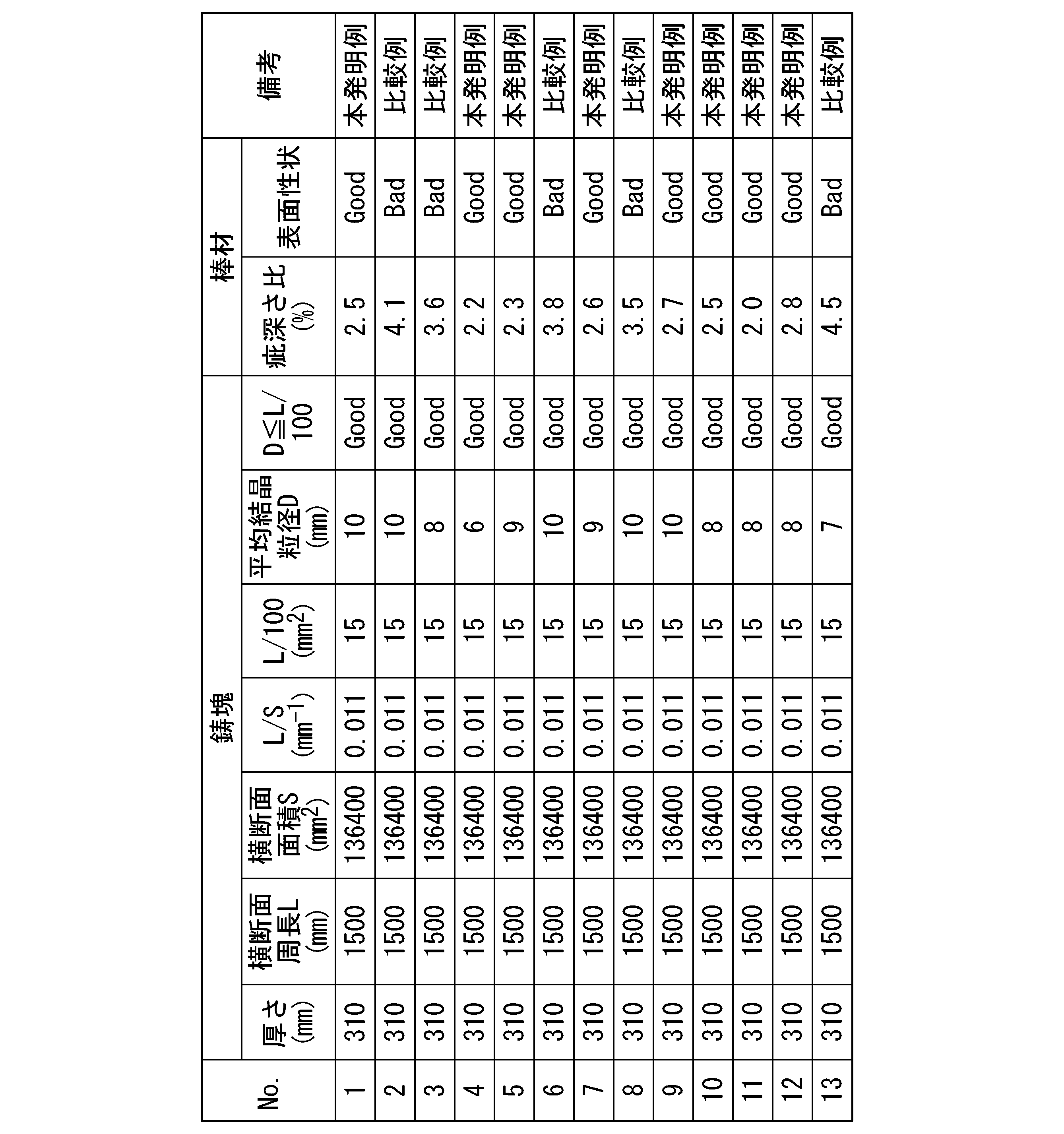
- the flaw depth ratio (%) (maximum surface flaw depth) / (circle of the bar) Converted diameter) ⁇ 100, when the flaw depth ratio is 3.0% or less, the surface texture is judged to be good (Good), and when the flaw depth ratio is more than 3.0%, the surface texture is It was judged as bad (Bad). Table 5 shows the results.
Landscapes
- Chemical & Material Sciences (AREA)
- Engineering & Computer Science (AREA)
- Mechanical Engineering (AREA)
- Materials Engineering (AREA)
- Metallurgy (AREA)
- Organic Chemistry (AREA)
- Manufacture And Refinement Of Metals (AREA)
Abstract
Description
0.02%≦[O]≦([Al]-[Fe]-0.5×[Mo]-0.5×[Nb]+1.0)/100 …(1)式
ここで、[X]は、単位を質量%とした場合の元素Xの含有量を示す。
Alはα安定化元素であり、α相の分率を増加するために含有させる。本実施形態に係る熱間加工用α+β型チタン合金鋳塊においては、Al含有量が少なすぎると、加熱時の表層酸化が進みやすくスケールや酸化硬化層の厚みが増すこととなり、その結果、棒材にしたときにその表面性状が劣化する。そのため、Alの含有量は2.5%以上とする。Alの含有量が多くなりすぎると、延性、靭性が低下し、その結果、棒材にしたときにその表面性状が劣化するので、Alの含有量は8.0%以下とする。Alの含有量は、好ましくは、2.6%以上であり、さらに好ましくは、2.7%以上、より一層好ましくは3.5%以上である。また、Alの含有量は、好ましくは、7.5%以下であり、更に好ましくは、7.0%以下、より一層好ましくは6.5%以下である。
Feは、β相を安定化する元素であり、Feがチタン合金鋳塊に含有されると強度が向上する。また、Feの含有量が0.5%未満であると、β相による粒成長抑制効果が低下して結晶粒が粗大化しやすくなるため、疵が深くなることとなり、その結果、棒材にしたときにその表面性状が劣化する。そのため、Feの含有量は、0.5%以上とする。一方、Feの含有量が3.0%超であると、延性、靭性が低下し、その結果、棒材にしたときにその表面性状が劣化するので、Feの含有量は3.0%以下とする。Feの含有量は、好ましくは、0.6%以上であり、更に好ましくは、0.7%以上である。また、Feの含有量は、好ましくは、2.9%以下であり、更に好ましくは、2.8%以下、より一層好ましくは2.5%以下である。
本発明のチタン合金鋳塊は、上記Tiの一部に代えて、Sn、Zr、Mo、Cu、及びNbの1種以上を、各々3.0%以下の範囲で含有させ、Siを3.00%以下の範囲で含有させてもよい。
Oはα安定化元素であり、α相の分率を増加させ、強度を向上させる作用を持つ。また、O含有量を0.02%未満とすると、精錬コストの著しい上昇を招き、低コスト化の効果を得ることができない。よって、O含有量は0.02%以上である。O含有量は0.03%以上であってもよいし、0.04%以上であってもよい。一方で、O含有量が過剰であると粒界α相が生成し易くなる。また、本実施形態に係る熱間加工用α+β型チタン合金鋳塊が3Dプリンター用の金属粉末として用いられる粉末の出発原料として用いられる場合、3Dプリンターにより造形された造形物の強度を確保するために、本実施形態に係る熱間加工用α+β型チタン合金鋳塊のO含有量は、強度向上のために必要なO含有量よりもやや低めの含有量とする。チタン合金鋳塊を出発原料として製造されたチタン合金棒材を3Dプリンターに用いられる材料粉末にすると、体積に対する表面積の比率が増加するため、表面酸化皮膜の影響が大きくなりO含有量が高くなる。このチタン合金粉末のO含有量が3Dプリンターで製造された造形物のO含有量となる。そして、3Dプリンターで製造された造形物の強度は、当該造形物のO含有量に応じた強度となる。そのため、本実施形態に係る熱間加工用α+β型チタン合金鋳塊のO含有量は、強度向上のために必要なO含有量よりもやや低めの含有量とする。よって、O含有量は、0.08%以下とする。O含有量は、0.07%以下であってもよい。
ただし、α安定化元素としてAlとO、β安定化元素としてFeを含有するα+β型のチタン合金では、Feの拡散速度が速く、かつ、Feのα相への固溶限が小さいために、β相からα+β域への変態の過程でβ粒界に粒界α相が析出し、割れの起点となる。また、Oも粒界α相の形成を促進し、割れの起点となる。Mo及びNbは、Feと同様に粒界α相の析出を促進する元素である。そのため、本実施形態に係る熱間加工用α+β型チタン合金鋳塊では、表面疵を抑制する観点から、O含有量を制御する。本発明者らの検討の結果、Al含有量、Fe含有量、Mo含有量、及びNb含有量に応じて、表面疵が抑制されるO含有量の範囲があることがわかった。単位を質量%としたときの、α安定化元素であるAlの含有量[Al]、Moの含有量[Mo]、Nb含有量[Nb]、及びβ安定化元素であるFeの含有量[Fe]を用いて、O含有量[O]が、0.02%≦[O]≦([Al]-[Fe]-0.5×[Mo]-0.5×[Nb]+1.0)/100を満足することにより、棒材における表面疵を抑制できる。したがって、本実施形態に係る熱間加工用α+β型チタン合金鋳塊では、さらに、Feの含有量、Alの含有量、Mo含有量、Nb含有量、及びOの含有量は、下記(1)式を満たす必要がある。
0.02%≦[O]≦([Al]-[Fe]-0.5×[Mo]-0.5×[Nb]+1.0)/100 …(1)式
ここで、[X]は元素Xの含有量(質量%)を示す。なお、Mo含有量が0の場合は[Mo]に0を代入し、Nb含有量が0の場合は[Nb]に0を代入する。
本実施形態に係る熱間加工用α+β型チタン合金鋳塊は、横断面の面積S(mm2)に対する横断面の周長L(mm)の比L/Sが0.010以上である。
本実施形態に係る熱間加工用α+β型チタン合金鋳塊では、α+β型チタン合金鋳塊の長手方向のうちの2つの端面のうちの一方の端面から他の端面に向かって、α+β型チタン合金鋳塊の長手方向の全長に対して20~80%の部分における、α+β型チタン合金鋳塊の表面から長手方向の中心軸に向かって10mmの位置での鋳造組織の平均結晶粒径Dが10mm以下であり、かつ、平均結晶粒径Dと横断面の周長LがD≦L/100を満たす。本実施形態に係る熱間加工用α+β型チタン合金鋳塊の組織をこのような組織にすることにより、圧延中に鋳塊の周方向に圧縮ひずみが作用する際に、それぞれの結晶粒界におけるひずみが緩和されることとなり、当該チタン合金鋳塊を棒材に熱間圧延する際の割れやボイドの発生が抑えられる。その結果、棒材表面に深い疵が形成されるのを抑えることができる。なお、以下では、α+β型チタン合金鋳塊の長手方向の2つの端面のうちの一方の端面から他端に向かい、α+β型チタン合金鋳塊の長手方向の全長に対して20~80%の部分を長手方向の中央部と呼称することがある。
本実施形態に係る熱間加工用α+β型チタン合金鋳塊は、その厚さが80mm以上である。
なお、本実施形態に係る熱間加工用α+β型チタン合金鋳塊の幅は、鋳型の大きさにより決まり、特に規定する必要はない。ただし、その下限は厚さ以上であってもよく、上限は2m以下であってもよい。なお、ここでいう幅とは、横断面が矩形である場合は横断面の長辺の長さである。また、横断面が五角形以上の多角形である場合は、チタン合金鋳塊の幅は、厚さと等しい。
(チタン合金鋳塊、棒材の製造)
表1に示すNo.1~29について、電子ビーム溶解法(EBM)にてチタン合金鋳塊を製造した。ハースから表1に示す形状の鋳型に注ぐチタン合金の溶湯の注湯温度を融点+200℃以下(No.1のみ融点+200℃超)、注湯速度0.05~2.0ton/h、鋳型表面から20mmより中央側の電子ビームの平均照射密度を0.05~0.10kW/cm2、鋳型表面から20mm以内の電子ビームの平均照射密度を鋳型表面から20mmより中央側の電子ビームの平均照射密度の50~100%、すなわち照射比率50~100%として、表2に示す化学組成及び表3A、3Bに示す横断面周長L及び横断面面積S並びに平均結晶粒径Dを有するチタン合金鋳塊を製造した。なお、表1では、鋳型表面から20mmより中央側の電子ビームの平均照射密度を「中央部平均照射密度」と記載し、鋳型表面から20mm以内の電子ビームの平均照射密度を「表面側平均照射密度」と記載している。電子ビーム銃の出力を一定とした状態で、鋳型表面から20mmより内側に位置する溶湯に照射する電子ビームの走査速度と、鋳型の内面から20mm以内に位置する溶湯に照射する電子ビームの走査速度とを変更することにより、平均照射密度を制御した。

各チタン合金鋳塊のAl含有量、Fe含有量、Mo含有量及びNb含有量は、「JIS H 1632-2:2014 チタン-ICP発光分光分析方法-第2部:パラジウム、マンガン、鉄、マグネシウム、けい素、アルミニウム、バナジウム、ニッケル、クロム、すず、銅、モリブデン、ジルコニウム、ニオブ、タンタル、コバルト及びイットリウム定量方法」に準拠して測定された。チタン合金鋳塊のO含有量は、「JIS H 1620:1995 チタン及びチタン合金中の酸素定量方法」に準拠して測定された。実施例1では、Al、Fe及びO以外に、チタン合金鋳塊における含有量を意図的に制御した元素は無いため、Ti及び表2に示した元素以外は、不純物であるとした。また、Mo含有量及びNb含有量は、不純物と見做せる範囲であったため、それぞれの含有量を0%とみなした。
表2にチタン合金鋳塊の化学組成、及び、(1)式:0.02%≦[O]≦([Al]-[Fe]-0.5×[Mo]-0.5×[Nb]+1.0)/100を満足するか否かを示す。表2の「(1)式合否」の項目に、(1)式を満たす場合をGoodと表記し、満たさない場合をBadと表記した。

製造された各チタン合金鋳塊の凝固時の収縮は、横断面の面積Sに対する横断面の周長Lの比L/Sの評価にほとんど影響しない。そのため、各チタン合金鋳塊の横断面の面積S及び横断面の周長Lは、鋳型の断面形状から算出した。
平均結晶粒径Dの測定は以下の方法で行った。まず、各鋳塊の長手方向のうちの2つの端面のうちの一方の端面から他の端面に向かって鋳塊の長手方向の全体の長さに対して50%の位置において、長手方向に対して垂直な方向に鋳塊を切断して得られた切断面をエメリー研磨紙及びバフ研磨により研磨した。次いで、硝酸の濃度が10質量%でありフッ酸の濃度が5質量%である硝フッ酸を用いて研磨後の切断面を腐食した。腐食した切断面での短辺から中心方向に5mmの位置において、粒界の数を測定した。
得られた棒材について棒材表面に目視で疵が観察された部位の5か所ずつについて、棒材の軸方向に対して垂直方向に切断し、切断面を研磨して鏡面状に仕上げた後、光学顕微鏡を使って、表面疵の深さを測定した。詳細には、長手方向の棒材の中央部において、棒材表面に目視で疵が確認された部位の5か所のそれぞれで、棒材の軸方向に対して垂直な断面を得た。5か所の上記断面を光学顕微鏡で観察倍率を15倍として観察し、各断面で得られた最大深さの平均値を下記式における最大表面疵深さとした。長手方向の棒材の中央部において目視で疵が確認された部位が5か所未満である場合は、目視で疵が確認された部位を基に最大表面疵深さを算出した。また、長手方向の棒材の中央部において目視で疵が確認された部位が6か所以上である場合は、大きい疵から5か所を測定した。疵が一視野に収まらない場合は、視野を移動させて疵深さを算出した。
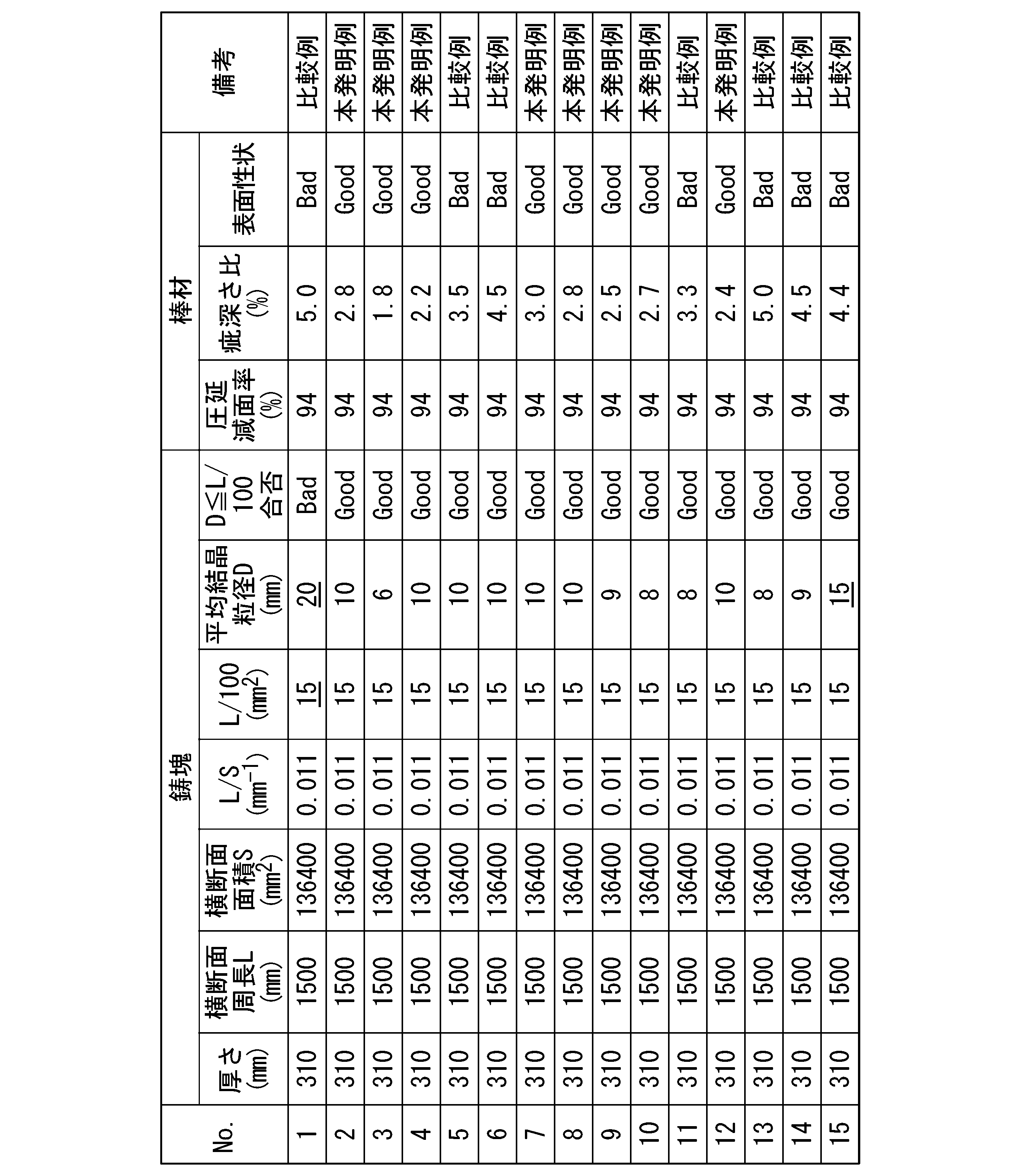

No.15、26は、照射比率が好ましい範囲を外れており、粒径が本発明の範囲を外れたため、圧延後の表面性状が劣る結果となった。
No.22は、照射比率が好ましい範囲を外れ、かつ、横断面の面積Sに対する横断面の周長Lの比L/Sが本発明の範囲を外れており、粒径が本発明の範囲を外れたため、圧延後の表面性状が劣る結果となった。
No.29は、平均結晶粒径Dと横断面の周長Lの関係D≦L/100を満たしていないため、圧延後の表面性状が劣る結果となった。
No.13は、チタン合金鋳塊のFe含有量が多く、圧延後の表面性状が劣る結果となった。
No.14は、チタン合金鋳塊のAl含有量が多く、圧延後の表面性状が劣る結果となった。
No.20は、チタン合金鋳塊のFe含有量が少なく、圧延後の表面性状が劣る結果となった。
No.21は、チタン合金鋳塊のAl含有量が少なく、圧延後の表面性状が劣る結果となった。
No.23は、横断面の面積Sに対する横断面の周長Lの比L/Sが0.010未満であり、圧延後の表面性状が劣る結果となった。
No.28は、平均結晶粒径Dと横断面の周長Lの関係D≦L/100を満たしていないため、圧延中に鋳塊の周方向に圧縮ひずみが作用する際に、それぞれの結晶粒界におけるひずみが緩和されず、ボイドが発生し、圧延後の表面性状が劣る結果となった。
(チタン合金鋳塊、棒材の製造)
鋳抜き方向に対して垂直な断面が310mm×440mmの鋳型を用いて、注湯温度を融点+200℃以下、注湯速度0.5ton/h、鋳型表面から20mmより中央側の電子ビームの平均照射密度0.10kW/cm2、鋳型表面から20mm以内の電子ビーム照射密度を中央部の50~80%、すなわち照射比率70%として、表4に示す化学組成、平均結晶粒径Dを有するチタン合金鋳塊を製造した。製造したチタン合金鋳塊の長さは4200mmであった。その後、実施例1と同様に、各チタン合金鋳塊を1200℃に加熱後、リバース圧延及び孔型圧延によりφ100mmまで減面率94%の圧延を行い、棒材を得た。
チタン合金鋳塊の化学組成は、以下の方法で測定された。各チタン合金鋳塊のAl含有量、Fe含有量、Mo含有量及びNb含有量は、実施例1と同様にして測定された。チタン合金鋳塊のO含有量は、「JIS H 1620:1995 チタン及びチタン合金中の酸素定量方法」に準拠して測定された。Si含有量、Zr含有量、Sn含有量及びCu含有量は、「JIS H 1632-2:2014 チタン-ICP発光分光分析方法-第2部:パラジウム、マンガン、鉄、マグネシウム、けい素、アルミニウム、バナジウム、ニッケル、クロム、すず、銅、モリブデン、ジルコニウム、ニオブ、タンタル、コバルト及びイットリウム定量方法」に準拠して測定された。
表4にチタン合金鋳塊の化学組成、及び、(1)式:0.02%≦[O]≦([Al]-[Fe]-0.5×[Mo]-0.5×[Nb]+1.0)/100を満足するか否かを示す。表4の「(1)式合否」の項目に、(1)式を満たす場合をGoodと表記し、満たさない場合をBadと表記した。また、表4中の「-」は、意図した添加を行っていないことを示す。

平均結晶粒径Dの測定は、実施例1と同様の方法で行った。表5の「D≦L/100」の項目においては、平均結晶粒径DがD≦L/100を満足するものをGoodと表記し、平均結晶粒径DがD≦L/100を満足しないものをBadと表記した。
得られた棒材について棒材表面に目視で疵が観察された部位の5か所ずつについて、棒材の軸方向に対して垂直方向に切断し、切断面を研磨して鏡面状に仕上げた後、光学顕微鏡を使って、表面疵の深さを測定した。
Claims (2)
- 熱間加工用α+β型チタン合金鋳塊であって、
質量%で、
Al:2.5~8.0%、
Fe:0.5~3.0%、
Sn:0~3.0%、
Zr:0~3.0%、
Mo:0~3.0%、
Si:0~3.00%、
Cu:0~3.0%、
Nb:0~3.0%、及び、
下記(1)式を満たす量のOを含有し、残部がTi及び不純物である化学組成を有し、
前記α+β型チタン合金鋳塊の長手方向に対し垂直な断面である横断面の面積S(mm2)に対する前記横断面の周長L(mm)の比L/Sが0.010以上であり、
前記α+β型チタン合金鋳塊の長手方向の2つの端面のうちの一方の前記端面から他の前記端面に向かって、前記α+β型チタン合金鋳塊の長手方向の全長に対して20~80%の部分において、前記α+β型チタン合金鋳塊の表面から前記α+β型チタン合金鋳塊の長手方向の中心軸に向かって10mmの位置での鋳造組織の平均結晶粒径DがD≦10mm、かつD≦L/100を満たし、
前記α+β型チタン合金鋳塊の厚さが80mm以上であることを特徴とする、熱間加工用α+β型チタン合金鋳塊。
0.02%≦[O]≦([Al]-[Fe]-0.5×[Mo]-0.5×[Nb]+1.0)/100 …(1)式
ここで、[X]は、単位を質量%とした場合の元素Xの含有量を示す。 - 前記Tiの一部に代えて、Sn、Zr、Mo、Cu、及びNbの1種以上を各3.0%以下含有し、Siを3.00%以下含有する、請求項1に記載の熱間加工用α+β型チタン合金鋳塊。
Priority Applications (3)
| Application Number | Priority Date | Filing Date | Title |
|---|---|---|---|
| PCT/JP2021/007931 WO2022185409A1 (ja) | 2021-03-02 | 2021-03-02 | 熱間加工用α+β型チタン合金鋳塊 |
| JP2023503569A JP7623611B2 (ja) | 2021-03-02 | 2021-03-02 | α+β型チタン合金鋳塊及び棒材の製造方法 |
| CN202180091977.7A CN116710582A (zh) | 2021-03-02 | 2021-03-02 | 热加工用α+β型钛合金铸锭 |
Applications Claiming Priority (1)
| Application Number | Priority Date | Filing Date | Title |
|---|---|---|---|
| PCT/JP2021/007931 WO2022185409A1 (ja) | 2021-03-02 | 2021-03-02 | 熱間加工用α+β型チタン合金鋳塊 |
Publications (1)
| Publication Number | Publication Date |
|---|---|
| WO2022185409A1 true WO2022185409A1 (ja) | 2022-09-09 |
Family
ID=83153958
Family Applications (1)
| Application Number | Title | Priority Date | Filing Date |
|---|---|---|---|
| PCT/JP2021/007931 Ceased WO2022185409A1 (ja) | 2021-03-02 | 2021-03-02 | 熱間加工用α+β型チタン合金鋳塊 |
Country Status (3)
| Country | Link |
|---|---|
| JP (1) | JP7623611B2 (ja) |
| CN (1) | CN116710582A (ja) |
| WO (1) | WO2022185409A1 (ja) |
Citations (3)
| Publication number | Priority date | Publication date | Assignee | Title |
|---|---|---|---|---|
| WO2014163086A1 (ja) * | 2013-04-01 | 2014-10-09 | 新日鐵住金株式会社 | 熱間圧延用チタン鋳片およびその製造方法 |
| WO2016051511A1 (ja) * | 2014-09-30 | 2016-04-07 | 新日鐵住金株式会社 | 分塊工程や精整工程を省略しても熱間圧延後の表面性状に優れた熱間圧延用チタン鋳片およびその製造方法 |
| WO2017018511A1 (ja) * | 2015-07-29 | 2017-02-02 | 新日鐵住金株式会社 | 熱間圧延用チタン材 |
Family Cites Families (6)
| Publication number | Priority date | Publication date | Assignee | Title |
|---|---|---|---|---|
| JPH03285028A (ja) * | 1990-03-30 | 1991-12-16 | Daido Steel Co Ltd | チタンおよびチタン合金鋳塊の製造方法 |
| JP2004277873A (ja) * | 2003-03-12 | 2004-10-07 | Nippon Sangyo Kagaku Kenkyusho | ボロンを添加したチタン合金 |
| JP2014233753A (ja) * | 2013-06-05 | 2014-12-15 | 新日鐵住金株式会社 | 分塊工程や精整工程を省略しても熱間圧延後の表面性状に優れた工業用純チタンインゴットおよびその製造方法 |
| KR20170045273A (ko) * | 2014-09-30 | 2017-04-26 | 신닛테츠스미킨 카부시키카이샤 | 표면 결함이 발생하기 어려운 열간 압연용 티타늄 주조편 및 그 제조 방법 |
| JP6933255B2 (ja) * | 2017-08-03 | 2021-09-08 | 日本製鉄株式会社 | チタン塊およびその製造方法、ならびに、チタンスラブ |
| JP7256385B2 (ja) * | 2019-06-14 | 2023-04-12 | 日本製鉄株式会社 | チタン合金鋳塊の製造方法および製造装置 |
-
2021
- 2021-03-02 WO PCT/JP2021/007931 patent/WO2022185409A1/ja not_active Ceased
- 2021-03-02 CN CN202180091977.7A patent/CN116710582A/zh active Pending
- 2021-03-02 JP JP2023503569A patent/JP7623611B2/ja active Active
Patent Citations (3)
| Publication number | Priority date | Publication date | Assignee | Title |
|---|---|---|---|---|
| WO2014163086A1 (ja) * | 2013-04-01 | 2014-10-09 | 新日鐵住金株式会社 | 熱間圧延用チタン鋳片およびその製造方法 |
| WO2016051511A1 (ja) * | 2014-09-30 | 2016-04-07 | 新日鐵住金株式会社 | 分塊工程や精整工程を省略しても熱間圧延後の表面性状に優れた熱間圧延用チタン鋳片およびその製造方法 |
| WO2017018511A1 (ja) * | 2015-07-29 | 2017-02-02 | 新日鐵住金株式会社 | 熱間圧延用チタン材 |
Also Published As
| Publication number | Publication date |
|---|---|
| JP7623611B2 (ja) | 2025-01-29 |
| JPWO2022185409A1 (ja) | 2022-09-09 |
| CN116710582A (zh) | 2023-09-05 |
Similar Documents
| Publication | Publication Date | Title |
|---|---|---|
| JP6901049B2 (ja) | チタン合金板、チタン合金板の製造方法、銅箔製造ドラム及び銅箔製造ドラムの製造方法 | |
| US8668760B2 (en) | Method for the production of a β-γ-TiAl base alloy | |
| WO2014163087A1 (ja) | 熱間圧延用チタン鋳片およびその製造方法 | |
| CN103459063B (zh) | 热轧用钛板坯及其制造方法 | |
| JP2014233753A (ja) | 分塊工程や精整工程を省略しても熱間圧延後の表面性状に優れた工業用純チタンインゴットおよびその製造方法 | |
| JPWO2018052135A1 (ja) | メタルマスク用素材およびその製造方法 | |
| WO2014163086A1 (ja) | 熱間圧延用チタン鋳片およびその製造方法 | |
| JP6075384B2 (ja) | 熱間圧延用チタン鋳片およびその製造方法 | |
| EP3702057A1 (en) | Production method for hot-rolled titanium plate | |
| JP5421873B2 (ja) | 強度異方性に優れた高強度α+β型チタン合金板および高強度α+β型チタン合金板の製造方法 | |
| JP6075387B2 (ja) | 表面疵の発生し難い熱間圧延用チタン鋳片およびその製造方法 | |
| WO2022185409A1 (ja) | 熱間加工用α+β型チタン合金鋳塊 | |
| JP5421872B2 (ja) | 曲げ加工性および曲げ異方性に優れた高強度α+β型チタン合金板並びに高強度α+β型チタン合金板の製造方法 | |
| JP2024155480A (ja) | 鋳塊 | |
| KR101953487B1 (ko) | 표면 결함이 발생하기 어려운 열간 압연용 티타늄 주조편 및 그 제조 방법 | |
| CN107075688A (zh) | 热轧用钛铸坯及其制造方法 | |
| JP2007308769A (ja) | アルミニウム合金厚板の製造方法およびアルミニウム合金厚板 | |
| JP7372532B2 (ja) | チタン合金丸棒およびコネクティングロッド | |
| JP2025135880A (ja) | 高耐食性Ni基合金 | |
| JP4220825B2 (ja) | 純チタン圧延コイル |
Legal Events
| Date | Code | Title | Description |
|---|---|---|---|
| 121 | Ep: the epo has been informed by wipo that ep was designated in this application |
Ref document number: 21928985 Country of ref document: EP Kind code of ref document: A1 |
|
| ENP | Entry into the national phase |
Ref document number: 2023503569 Country of ref document: JP Kind code of ref document: A |
|
| WWE | Wipo information: entry into national phase |
Ref document number: 202180091977.7 Country of ref document: CN |
|
| NENP | Non-entry into the national phase |
Ref country code: DE |
|
| 122 | Ep: pct application non-entry in european phase |
Ref document number: 21928985 Country of ref document: EP Kind code of ref document: A1 |