WO2022181794A1 - 電池用極板群、蓄電池、組電池、電動車、電池用セパレータ、電池用セパレータの製造方法、及び、電池用極板群の製造方法 - Google Patents
電池用極板群、蓄電池、組電池、電動車、電池用セパレータ、電池用セパレータの製造方法、及び、電池用極板群の製造方法 Download PDFInfo
- Publication number
- WO2022181794A1 WO2022181794A1 PCT/JP2022/008032 JP2022008032W WO2022181794A1 WO 2022181794 A1 WO2022181794 A1 WO 2022181794A1 JP 2022008032 W JP2022008032 W JP 2022008032W WO 2022181794 A1 WO2022181794 A1 WO 2022181794A1
- Authority
- WO
- WIPO (PCT)
- Prior art keywords
- separator
- electrode plate
- battery
- main
- strap
- Prior art date
- Legal status (The legal status is an assumption and is not a legal conclusion. Google has not performed a legal analysis and makes no representation as to the accuracy of the status listed.)
- Ceased
Links
Images


Classifications
-
- H—ELECTRICITY
- H01—ELECTRIC ELEMENTS
- H01M—PROCESSES OR MEANS, e.g. BATTERIES, FOR THE DIRECT CONVERSION OF CHEMICAL ENERGY INTO ELECTRICAL ENERGY
- H01M10/00—Secondary cells; Manufacture thereof
- H01M10/05—Accumulators with non-aqueous electrolyte
- H01M10/058—Construction or manufacture
- H01M10/0585—Construction or manufacture of accumulators having only flat construction elements, i.e. flat positive electrodes, flat negative electrodes and flat separators
-
- H—ELECTRICITY
- H01—ELECTRIC ELEMENTS
- H01M—PROCESSES OR MEANS, e.g. BATTERIES, FOR THE DIRECT CONVERSION OF CHEMICAL ENERGY INTO ELECTRICAL ENERGY
- H01M10/00—Secondary cells; Manufacture thereof
- H01M10/06—Lead-acid accumulators
- H01M10/12—Construction or manufacture
-
- H—ELECTRICITY
- H01—ELECTRIC ELEMENTS
- H01M—PROCESSES OR MEANS, e.g. BATTERIES, FOR THE DIRECT CONVERSION OF CHEMICAL ENERGY INTO ELECTRICAL ENERGY
- H01M50/00—Constructional details or processes of manufacture of the non-active parts of electrochemical cells other than fuel cells, e.g. hybrid cells
- H01M50/40—Separators; Membranes; Diaphragms; Spacing elements inside cells
- H01M50/46—Separators, membranes or diaphragms characterised by their combination with electrodes
-
- H—ELECTRICITY
- H01—ELECTRIC ELEMENTS
- H01M—PROCESSES OR MEANS, e.g. BATTERIES, FOR THE DIRECT CONVERSION OF CHEMICAL ENERGY INTO ELECTRICAL ENERGY
- H01M50/00—Constructional details or processes of manufacture of the non-active parts of electrochemical cells other than fuel cells, e.g. hybrid cells
- H01M50/40—Separators; Membranes; Diaphragms; Spacing elements inside cells
- H01M50/463—Separators, membranes or diaphragms characterised by their shape
- H01M50/466—U-shaped, bag-shaped or folded
-
- H—ELECTRICITY
- H01—ELECTRIC ELEMENTS
- H01M—PROCESSES OR MEANS, e.g. BATTERIES, FOR THE DIRECT CONVERSION OF CHEMICAL ENERGY INTO ELECTRICAL ENERGY
- H01M50/00—Constructional details or processes of manufacture of the non-active parts of electrochemical cells other than fuel cells, e.g. hybrid cells
- H01M50/50—Current conducting connections for cells or batteries
- H01M50/531—Electrode connections inside a battery casing
-
- Y—GENERAL TAGGING OF NEW TECHNOLOGICAL DEVELOPMENTS; GENERAL TAGGING OF CROSS-SECTIONAL TECHNOLOGIES SPANNING OVER SEVERAL SECTIONS OF THE IPC; TECHNICAL SUBJECTS COVERED BY FORMER USPC CROSS-REFERENCE ART COLLECTIONS [XRACs] AND DIGESTS
- Y02—TECHNOLOGIES OR APPLICATIONS FOR MITIGATION OR ADAPTATION AGAINST CLIMATE CHANGE
- Y02E—REDUCTION OF GREENHOUSE GAS [GHG] EMISSIONS, RELATED TO ENERGY GENERATION, TRANSMISSION OR DISTRIBUTION
- Y02E60/00—Enabling technologies; Technologies with a potential or indirect contribution to GHG emissions mitigation
- Y02E60/10—Energy storage using batteries
-
- Y—GENERAL TAGGING OF NEW TECHNOLOGICAL DEVELOPMENTS; GENERAL TAGGING OF CROSS-SECTIONAL TECHNOLOGIES SPANNING OVER SEVERAL SECTIONS OF THE IPC; TECHNICAL SUBJECTS COVERED BY FORMER USPC CROSS-REFERENCE ART COLLECTIONS [XRACs] AND DIGESTS
- Y02—TECHNOLOGIES OR APPLICATIONS FOR MITIGATION OR ADAPTATION AGAINST CLIMATE CHANGE
- Y02P—CLIMATE CHANGE MITIGATION TECHNOLOGIES IN THE PRODUCTION OR PROCESSING OF GOODS
- Y02P70/00—Climate change mitigation technologies in the production process for final industrial or consumer products
- Y02P70/50—Manufacturing or production processes characterised by the final manufactured product
Definitions
- the present disclosure relates to a battery electrode plate group, a storage battery, an assembled battery, an electric vehicle, a battery separator, a method for manufacturing a battery separator, and a method for manufacturing a battery electrode plate group.
- Patent Literature 1 discloses a method for manufacturing an electrode plate containing a bag separator for a lead-acid battery.
- the negative electrode plate is sandwiched by folding the separator.
- a bag-like separator for accommodating the negative electrode plate is provided.
- a storage battery is formed by stacking a bag-shaped separator that accommodates a negative electrode plate and a positive electrode plate.
- the ears of the negative electrode plate are exposed from the separator.
- the ear portion is a portion for electrically connecting to another negative electrode plate, and is usually welded to a conductive member called a strap.
- a conductive member called a strap.
- An object of one aspect of the present disclosure is to provide a battery electrode plate group, a storage battery, an assembled battery, an electric vehicle, a battery separator, a method for manufacturing a battery separator, which can suppress breakage of the separator when the strap and the electrode plate are welded together, Another object of the present invention is to provide a method for manufacturing an electrode plate group for a battery.
- a battery electrode plate group includes a first electrode plate and a second electrode plate that overlap each other in the stacking direction, a separator that covers at least part of the first electrode plate when viewed from the stacking direction, and a strap disposed above the separator and electrically connected to the second electrode plate in a vertical direction intersecting the
- the plate has a second body portion and an ear portion that protrudes upward from the second body portion in the vertical direction and is welded to the strap. The upper end of the lower separator hangs down.
- the upper end portion of the separator which is positioned above the first main body portion in the vertical direction and below the strap, hangs down.
- the distance between the strap's upper end and the portion where the strap and the ear of the second electrode plate are welded can be increased compared to when the separator's upper end does not droop. Therefore, according to one aspect of the present disclosure, it is possible to suppress breakage of the separator when the strap and the electrode plate are welded, compared to the case where the upper end portion of the separator does not hang down.
- the separator has a first main portion located on one end side in the stacking direction, a second main portion located on the other end side in the stacking direction relative to the first main portion, and a separator above the first main portion in the vertical direction. and an upper joint joining the first main section and the second main section, wherein the upper end may include the upper joint.
- the upper end portion of the separator tends to sag compared to the case where the separator is not provided with the upper joint portion.
- the first electrode plate protrudes upward from the first main body in the vertical direction and has another ear portion exposed from the opening of the separator, and is separate from the upper joint portion in the direction orthogonal to the stacking direction and the vertical direction.
- a closure is provided between the ear and the first and second bodies contacting each other, and the contact of the first and second bodies at the closure forms an upper joint. may be maintained by the influence of the deformation of the first main portion and the second main portion accompanying the .
- the opening of the separator can be reduced without enlarging the joint. Therefore, it is possible to prevent the active material of the first electrode plate from flowing out of the separator while suppressing the damage to the separator due to the formation of the joint.
- the upper joint portion may be positioned between the first body portion and the strap in the vertical direction, and at least one of the upper end and the lower end of the upper joint portion may be provided with an inflection portion of the separator. In this case, the upper end portion of the separator can be reliably hung.
- the battery electrode plate group includes a plurality of first electrode plates, a plurality of second electrode plates, and a plurality of separators, and an ear portion included in each of the plurality of second electrode plates is welded to the strap.
- the direction in which the upper end portion hangs down may be the same. In this case, the separators are less likely to break when the strap and the second electrode plates are welded together.
- the battery electrode plate group includes a plurality of first electrode plates and a plurality of second electrode plates, and the ear portion included in each of the plurality of second electrode plates is welded to the strap.
- the first body portion included in each of the first electrode plates may be covered with the separator when viewed from the stacking direction, and the directions in which the plurality of upper end portions included in the separator hang down may be aligned. In this case, the plurality of upper end portions are less likely to break when the strap and the second pole plates are welded together.
- the separator is provided with at least one rib, and the rib may abut on a corner of the first main body facing the upper end of the separator in the vertical direction. In this case, breakage of the portion of the separator that contacts the corner of the first main body can be suppressed.
- the separator may have a regulating portion positioned below the first body portion in the vertical direction and regulating the rising of the separator. In this case, it is possible to restrict the separator from rising and approaching the strap.
- the restricting portion may include a bent portion where the separator is folded back. In this case, the restricting portion can be easily formed in the separator.
- the restricting portion may have a lower joining portion that is positioned between the first body portion and the lower end of the separator in the vertical direction and joins a portion of the separator to the other portion. In this case, a restricting portion is provided at a desired position.
- a storage battery includes the above-described battery electrode plate group and a container that houses the battery electrode plate group.
- This storage battery includes a battery electrode plate group capable of suppressing breakage of the separator when the strap and the electrode plate are welded. Therefore, for example, it is possible to satisfactorily prevent a damaged portion of the separator from becoming a short-circuit path between the first electrode plate and the second electrode plate. Therefore, in the storage battery, it is possible to satisfactorily suppress short circuits between the first electrode plate and the second electrode plate that overlap each other with the battery separator interposed therebetween.
- An assembled battery includes the storage battery described above.
- This assembled battery includes a storage battery that includes a battery electrode plate group capable of suppressing breakage of a separator when a strap and electrode plates are welded together. Therefore, in the storage battery, it is possible to satisfactorily suppress short circuits between the first electrode plate and the second electrode plate that overlap each other with the battery separator interposed therebetween.
- An electric vehicle (or an electric vehicle) according to one aspect of the present disclosure includes the assembled battery.
- This electric vehicle includes a storage battery that includes a battery electrode plate group capable of suppressing breakage of a separator when a strap is welded to an electrode plate. Therefore, in the storage battery, it is possible to satisfactorily suppress short circuits between the first electrode plate and the second electrode plate that overlap each other with the battery separator interposed therebetween.
- a battery electrode plate group includes a first electrode plate and a second electrode plate that overlap each other in a first direction, and a separator that covers at least part of the first electrode plate when viewed from the first direction. and a strap disposed outside the separator and electrically connected to the second plate in a second direction orthogonal to the first direction.
- the first plate has a first body portion and the second plate has a second body portion and ears projecting from the second body portion toward the strap in a second direction and welded to the strap.
- the end portion of the separator located between the first body portion and the strap in the second direction has a proximal portion extending along the second direction and a portion closer to the strap than the proximal portion in the second direction. and a tip portion positioned closer to the strap than the inflection portion in the second direction, and the angle between the base end portion and the tip portion of the inflection portion is less than 180°. is.
- the end portion of the separator positioned between the first body portion and the strap includes a base end portion and an inflection portion positioned in order in the second direction. , and a distal portion, and the angle between the proximal portion and the distal portion at the inflection portion is less than 180°.
- the distance between the edge of the separator and the location where the strap and the ear of the second electrode plate are welded can be widened compared to the case where the edge of the separator is not provided with an inflection portion. Therefore, according to another aspect of the present disclosure, it is possible to suppress breakage of the separator when the strap and the electrode plate are welded together, as compared with the case where the end portion of the separator is not provided with an inflection portion.
- a battery separator is a battery separator for wrapping a first electrode plate housed in a case of a storage battery, the first main portion positioned on one end side in the first direction, and A base portion having a second main portion located on the other end side in the first direction, and a first end portion of the first main portion and a second end portion of the second main portion in a second direction orthogonal to the first direction. and a joint to be joined.
- the battery separator wraps the first electrode plate and is accommodated in the case, the first end and the second end are separated from each other in the second direction by the main body portion of the first electrode plate and the first electrode plate.
- a bent piece is provided by a portion of each of the first end and the second end positioned between the straps welded to a different second plate.
- the first end and the second end are arranged in the second direction to: Positioned between the main body portion of the first plate and a strap welded to a second plate different from the first plate, the bent strip is formed by a portion of each of the first end and the second end. is provided.
- the distance between the battery separator and the portion where the strap and the second electrode plate are welded can be increased compared to the case where the battery separator is not provided with the bent piece. Therefore, according to another aspect of the present disclosure, it is possible to suppress breakage of the battery separator when the strap and the electrode plate are welded together, compared to the case where the battery separator is not provided with the bending piece.
- the bending piece has a proximal portion, an inflection portion, and a distal portion which are arranged in order along the second direction, the proximal portion extending along the second direction, and the proximal portion and the distal portion.
- the angle with the tip portion may be less than 180°.
- the method for manufacturing the above battery separator includes a first step in which the first main portion and the second main portion are opposed to each other in the first direction, a first end of the first main portion and a second end of the second main portion and a second step of forming a joint portion by joining the portion, wherein the bending piece is formed along with the formation of the joint portion in the second step.
- the bent pieces can be formed without increasing the manufacturing steps of the battery separator.
- a method for manufacturing an electrode plate group for a battery comprising the method for manufacturing a separator for a battery includes, in a first step, disposing a first electrode plate between the first main portion and the second main portion; In the method, the joint portion is formed with the first electrode plate disposed between the first main portion and the second main portion, and the first electrode plate and the second electrode plate are laminated after the second step. After that, a third step of welding the ear portion of the second plate to the strap, wherein the bending piece is positioned between the body portion of the first plate and the strap in the second direction. In this case, since the bending piece is positioned between the main body portion of the first electrode plate and the strap in the second direction, it is possible to suppress breakage of the battery separator when welding the strap and the ear portion of the second electrode plate. become.
- a battery electrode plate group a storage battery, an assembled battery, an electric vehicle, a battery separator, a method for manufacturing a battery separator, which can suppress breakage of the separator when the strap and the electrode plate are welded together, And, it is possible to provide a method for manufacturing an electrode plate group for a battery.
- FIG. 1 is a schematic perspective view showing a partially broken storage battery according to the embodiment.
- FIG. 2(a) is a view showing the positive electrode viewed from the first direction
- FIG. 2(b) is an enlarged cross-sectional view taken along line IIb-IIb of FIG. 2(a).
- FIG. 3 is a plan view showing the negative electrode according to the embodiment.
- FIG. 4(a) is a plan view showing a separator sheet
- FIG. 4(b) is a schematic cross-sectional view taken along line IVb-IVb of FIG. 4(a).
- FIG. 5 is a plan view showing a negative electrode wrapped with a separator.
- FIG. 6 is a perspective view showing a negative electrode wrapped with a separator.
- FIG. 5 is a plan view showing a negative electrode wrapped with a separator.
- FIG. 7 is an enlarged view of the main parts of the electrode plate group and the strap.
- FIG. 8 is an enlarged schematic view of a portion surrounded by a dashed line in FIGS. 5 and 6.
- FIG. 9 is a cross-sectional view taken along line IX-IX of FIG. 8.
- FIG. 10 is an enlarged cross-sectional view of main parts of a separator and a negative electrode included in an electrode group according to a modification.
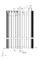
- FIG. 1 is a schematic perspective view showing a partially broken storage battery according to this embodiment.
- the storage battery 1 is, for example, a lead storage battery.
- the storage battery 1 is used, for example, as a battery for an automobile, a backup power source used in the event of a power failure, and a main power source for an electric vehicle (or an electric vehicle) such as an electric forklift.
- an assembled battery composed of a plurality of storage batteries 1 may be used.
- the electric vehicle may have an assembled battery including a plurality of storage batteries 1 .
- the storage battery 1 is, for example, a clad lead-acid battery with clad electrodes.
- the storage battery 1 includes an electrode plate group 3 , a positive electrode terminal 5A, a negative electrode terminal 5B, a supplementary water tap 6 and a case 7 .
- Case 7 has main body 8 and lid 9 .
- the main body 8 is a box-shaped container.
- the main body 8 is made of a material such as polypropylene.
- the main body 8 accommodates the electrode plate group 3 and an electrolytic solution.
- the main body 8 is composed of four side portions and a bottom portion.
- a lid 9 covers the opening of the body 8 .
- the lid 9 is provided with a positive electrode terminal 5A, a negative electrode terminal 5B, and a supplementary water tap 6 .
- a supplementary water tap 6 is provided between the positive terminal 5A and the negative terminal 5B.
- the electrode plate group 3 has multiple positive electrodes 10 , multiple negative electrodes 12 , and multiple separators 13 .
- positive electrodes 10 and negative electrodes 12 are alternately arranged.
- a separator 13 is positioned between the adjacent positive electrode 10 and negative electrode 12 . Therefore, the positive electrode 10, the separator 13 and the negative electrode 12 are stacked in order in a predetermined direction.
- the negative electrode 12 is located at the end of the positive electrode 10, the negative electrode 12, and the separator 13 in the direction in which they are arranged (hereinafter sometimes simply referred to as the “arrangement direction” or the “stacking direction”). are placed.
- the assembly of the positive electrode 10, the negative electrode 12, and the separator 13 is also called a battery electrode plate group (electrode group).
- the electrode plate group 3 and the electrolyte are accommodated in the main body 8, the electrolyte exists in the gap between the positive electrode 10 and the separator 13, in the separator 13, and the like.
- first direction X A direction perpendicular to the first direction X (vertical direction) is defined as a second direction Y
- second direction Y a direction perpendicular to the first direction X and the second direction Y
- third direction Z a direction perpendicular to the first direction X and the second direction Y
- the second direction Y corresponds to the direction in which the electrode plate group 3 is housed in the case 7 .
- the first direction X, the second direction Y, and the third direction Z are orthogonal to each other, but are not limited to this.
- the first direction X, the second direction Y, and the third direction Z may intersect each other.
- FIG. 2 is a view showing the positive electrode viewed from the first direction
- (b) of FIG. 2 is an enlarged cross-sectional view taken along line IIb-IIb of (a) of FIG.
- the positive electrode 10 is, for example, a clad positive electrode plate (second electrode plate).
- each positive electrode 10 is electrically connected to the positive electrode terminal 5A.
- Each positive electrode 10 and the positive electrode terminal 5A are electrically connected by a positive electrode strap 17, which is a conductive member made of metal or alloy.
- the positive electrode 10 includes a current collector 14 , a plurality of tubular bodies 15 (tubes) accommodating a portion of the current collector 14 , a positive electrode material 16 accommodated in the tubular bodies 15 , and attached to the current collector 14 . an upper link 21 and a lower link 22 .
- the current collector 14 has a plurality of core metals 14a, a connecting portion (not shown) that connects the plurality of core metals 14a and is covered by the upper connecting member 21, and ears 14c that protrude from the connecting portion.
- the current collector 14 is formed, for example, by casting.
- the constituent material of the current collector 14 may be any conductive material, and examples thereof include lead-calcium-tin based alloys, lead-antimony-arsenic based alloys, and other lead alloys. Lead alloys may include selenium, silver, bismuth, and the like.
- the plurality of core bars 14a are rod-shaped portions extending along the second direction Y and arranged in a row along the third direction Z.
- One end of each cored bar 14 a in the second direction Y is connected to a connecting portion (not shown) covered by the upper connecting seat 21 .
- the other end of each cored bar 14 a in the second direction Y is fixed to the lower connecting seat 22 .
- the length of each cored bar 14a is, for example, 170 to 650 mm.
- the length of each cored bar 14a may be 600 mm or less, or may be 450 mm or less.
- the connecting portion is a portion that supports the metal core 14a and the ear portion 14c, and extends along the third direction Z. As shown in FIG.
- the connecting portion is arranged on the positive electrode terminal 5A side in the second direction Y.
- the cored bar 14 a and the connecting portion are also referred to as a body portion (second body portion) of the positive electrode 10 .
- the ear portion 14 c is a terminal portion protruding in the second direction Y from the connecting portion, and is welded to the positive electrode strap 17 positioned above the positive electrode 10 , the negative electrode 12 and the separator 13 in the second direction Y.
- the protruding direction of the ear portion 14c is opposite to the protruding direction of the cored bar 14a.
- the ear portion 14 c protrudes upward from the connecting portion and is positioned on the lid 9 side in the second direction Y.
- the plurality of cylindrical bodies 15 are insulating members that constitute a group of active material holding tubes (cladding tubes).
- the active material holding tube group is an assembly of cylindrical porous tubes, also called a "gauntlet". For this reason, each cylindrical body 15 is provided with a plurality of holes. In this embodiment, the thickness of the cylindrical body 15 is uniform, but the thickness is not limited to this.
- Each cylindrical body 15 extends along the second direction Y and accommodates the corresponding cored bar 14a.
- Each tubular body 15 is, for example, a resin molding.
- the positive electrode material 16 is filled inside the cylindrical body 15 together with the metal core 14a. Therefore, the cored bar 14 a and the positive electrode material 16 are accommodated in the cylindrical body 15 . As shown in (b) of FIG. 2 , the positive electrode material 16 surrounds the metal core 14 a inside the cylindrical body 15 .
- Cathode material 16 includes an active material. Active materials include both active materials after chemical conversion and raw materials for active materials before chemical conversion.
- the positive electrode material 16 contains an active material after chemical conversion.
- the positive electrode material 16 after chemical conversion contains, for example, a raw material of a positive electrode active material.
- the cathode material 16 may include a cathode active material and an additive.
- the positive electrode active material is, for example, lead powder, red lead, or the like. Examples of additives include carbon materials, reinforcing short fibers, and the like.
- the positive electrode active material after chemical conversion is, for example, lead dioxide.
- the upper connecting member 21 is an insulating structure attached to the connecting portion of the current collector 14 and covers the connecting portion when viewed from the second direction Y.
- the upper connecting seat 21 seals one end of each tubular body 15 in the second direction Y.
- the upper linking member 21 is welded to each cylindrical body 15, but the present invention is not limited to this.
- the upper linking seat 21 and each cylindrical body 15 may be fixed to each other, for example, via an adhesive or the like.
- the upper connecting member 21 is provided by, for example, welding an insulating resin member to the current collector 14 .
- the lower connecting seat 22 is an insulating structure attached to a plurality of metal cores 14 a of the current collector 14 .
- the lower connecting member 22 is attached to the current collector 14 by, for example, inserting and fitting the metal core 14a of the current collector 14 into an insulating resin member.
- the lower connecting seat 22 seals the other end of each tubular body 15 in the second direction Y.
- the position of each cylindrical body 15 in the positive electrode 10 is fixed by the upper connecting seat 21 and the lower connecting seat 22 .
- the lower linking seat 22 is welded to each cylindrical body 15, but the present invention is not limited to this.
- the lower linking seat 22 and each cylindrical body 15 may be fixed to each other by, for example, an adhesive or the like.
- FIG. 3 is a plan view showing the negative electrode according to the embodiment.
- the negative electrode 12 is a negative electrode plate (first electrode plate) in the storage battery 1 and is electrically connected to the negative electrode terminal 5B.
- Each negative electrode 12 and the negative electrode terminal 5B are electrically connected by a negative electrode strap 18, which is a conductive member made of metal or alloy.
- the negative electrode 12 has a current collector 12a and a negative electrode material 12b.
- the current collector 12a is formed, for example, by casting, and has a negative electrode lattice 12c and ears 12d.
- the negative electrode grid 12c is a main body (first main body) of the negative electrode 12 and holds the negative electrode material 12b.
- the thickness of the portion of the negative electrode 12 where the negative electrode material 12b is held is greater than the thickness of the negative electrode grid 12c, but is not limited to this.
- the negative electrode material 12b may contain a negative electrode active material and an additive.
- the negative electrode active material is, for example, spongy lead.
- additives include barium sulfate, carbon materials, lignin, or reinforcing short fibers.
- the ear portion 12d is a terminal portion protruding from the negative electrode grid 12c along the second direction Y, and is welded to the negative electrode strap 18 positioned above the positive electrode 10, the negative electrode 12, and the separator 13 in the second direction Y.
- the ear portion 12 d protrudes upward along the second direction Y toward the negative electrode strap 18 .
- the ear portion 12d and the negative grid 12c do not overlap each other in the first direction X.
- the negative grid 12 c is covered with the separator 13 .
- Protrusions 12e and 12f are provided on the negative electrode grid 12c.
- the convex portions 12e and 12f are leg portions that are arranged at a predetermined interval and protrude outward from the negative electrode grid 12c.
- the protrusions 12e and 12f protrude in a direction opposite to the protruding direction of the ear portion 12d.
- the projection direction of the ear portion 12d and the projection direction of the projections 12e and 12f are orthogonal to the arrangement direction.
- the ear portions 12d and the negative electrode grid bodies 12c do not overlap each other in the arrangement direction.
- the separator 13 is a battery member (battery separator) for preventing a short circuit between the positive electrode 10 and the negative electrode 12 .
- the separator 13 electrically insulates between the positive electrode 10 and the negative electrode 12 while allowing ions to pass therethrough.
- materials (materials) for such a separator 13 include glass fibers, resins, inorganic substances, and the like.
- the separator 13 is a member that wraps at least a portion of the negative electrode 12 and covers the negative electrode 12 when viewed from the first direction. More specifically, the separator 13 covers the negative electrode lattice 12c and the projections 12e and 12f of the negative electrode 12, and the tabs 12d of the negative electrode 12 are exposed from the separator 13. As shown in FIG.
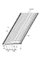
- FIG. 4(a) is a plan view showing a separator sheet.
- FIG. 4(b) is a schematic cross-sectional view taken along line IVb-IVb of FIG. 4(a).
- the separator sheet 30 has a main portion 31, a pair of edge portions 32 and 33, and a plurality of ribs .
- the main part 31 is a sheet-like part that is the main part of the separator sheet 30 and exhibits flexibility.
- the main portion 31 has a first principal surface 31a and a second principal surface 31b located on the opposite side of the first principal surface 31a in the first direction X. As shown in FIG. In the present embodiment, the first main surface 31a and the second main surface 31b have a rectangular shape when viewed from the first direction X, but this is not the only option.
- the pair of edge portions 32 and 33 are portions provided at both ends of the separator sheet 30 in the third direction Z.
- Each of the edge portions 32 and 33 extends from one end of the separator sheet 30 in the second direction Y (for example, the upper end of the page in FIG. 4A) to the other end (for example, the lower end of the page in FIG. 4A). extends up to Each of the edges 32, 33 may extend continuously or intermittently.
- the edge 32 is provided at one end of the separator sheet 30 in the third direction Z (for example, the left end of the paper surface in FIG. 4A), and the edge 33 is provided at the other end of the separator sheet 30 in the third direction Z (for example, It is provided on the right side of the paper surface in (a) of FIG.
- ribs different from the ribs 34 are provided on the pair of edge portions 32 and 33 .
- one or a plurality of ribs or the like extending from one end of the separator sheet 30 in the second direction Y to the other end may be provided on each of the pair of edge portions 32 and 33 .
- the plurality of ribs 34 are provided, for example, to improve the durability of the separator sheet 30 and improve the fluidity of the electrolytic solution in the case 7.
- a plurality of ribs 34 protrude from the main portion 31 along the first direction X and are spaced apart from each other.
- Each of the plurality of ribs 34 has a rectangular shape when viewed from the first direction X. As shown in FIG.
- Each of the plurality of ribs 34 extends from one end to the other end of the separator sheet 30 in the second direction Y and extends parallel to each other.
- the cross section of the rib 34 perpendicular to the extending direction of the rib 34 has a rectangular shape, but is not limited to this.
- the cross section may be, for example, trapezoidal or inverted trapezoidal.
- the dimension (width) of the ribs 34 along the third direction Z is 0.30% or more and 2.5% or less of the dimension of the separator sheet 30 along the third direction Z, for example.
- the dimension (height) of the rib 34 along the first direction X is, for example, greater than 100% and 1000% or less of the dimension (thickness) of the main portion 31 along the first direction X.
- the ribs 34 have a plurality of first ribs 34a provided on the first main surface 31a and a plurality of second ribs 34b provided on the second main surface 31b.
- the first rib 34a protrudes along the first direction X from the first major surface 31a.
- the second rib 34b protrudes from the second main surface 31b to the side opposite to the first rib 34a.
- the first rib 34a and the second rib 34b have the same shape and completely overlap each other.
- the portion of the separator sheet 30 where the ribs 34 are provided is also referred to as a thick portion TP1 of the separator sheet 30 (and the separator 13).
- the portion where the main portion 31 and the rib 34 overlap each other is also called a thick portion TP1. Therefore, the thick portion TP1 has ribs 34 .
- the thickness of the thick portion TP1 in this embodiment is equal to the thickness of the main portion 31 and the thickness of the first rib 34a. It corresponds to the sum of the height and the height of the second rib 34b.
- the second thickness T2 is, for example, greater than 100% of the first thickness T1. 2000% or less.
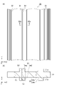
- FIG. 5 is a plan view showing a negative electrode wrapped with a separator.
- FIG. 6 is a perspective view showing a negative electrode wrapped with a separator.
- FIG. 7 is an enlarged view of the main parts of the electrode plate group and the strap.
- the separator 13 corresponds to a separator sheet bag-like processed product, and wraps the negative electrode 12 .
- the ear portion 12 d of the negative electrode 12 is exposed from the separator 13 , and the convex portions 12 e and 12 f of the negative electrode 12 are covered with the separator 13 .
- the separator 13 is formed by, for example, folding one separator sheet 30 in two along the second direction Y and then sealing desired portions. At this time, the separator sheet 30 is folded back on the side of the projections 12 e and 12 f of the negative electrode 12 in the second direction Y so that the negative electrode 12 is sandwiched between the separator sheets 30 .
- the separator sheet 30 may be folded in half as the negative electrode 12 moves.
- the aspect ratio between the dimension of the separator 13 along the second direction Y and the dimension of the separator 13 along the third direction Z is, for example, 1.4 or more and 4.0 or less.
- the aspect ratio may be 1.5 or more and 3.8 or less, 1.8 or more and 3.5 or less, or 2.0 or more and 3.0 or less.
- the separator 13 has a base portion 41 , a pair of seal portions 42 and 43 , a bent portion 44 and a joint portion 45 .
- the base portion 41 is a portion that accommodates the negative electrode grid 12c of the negative electrode 12 .
- the base portion 41 is composed of the main portion 31 of the separator sheet 30 and the edge portions 32, 33 (see FIG. 4(a)). Therefore, the base 41 has a first main surface 31a provided with the first ribs 34a and a second main surface 31b provided with the second ribs 34b (see (b) of FIG. 4).
- the first principal surface 31a faces the negative electrode 12, and the second principal surface 31b is an exposed surface. Therefore, the positive electrode 10 (see FIG. 1) in the electrode plate group 3 faces the second main surface 31 b of the separator sheet 30 .
- the portion of the base portion 41 that overlaps the negative electrode 12 in the first direction X is referred to as an inner portion 41a.
- a portion of the base portion 41 located outside the inner portion 41a as viewed from the first direction X is referred to as an outer portion 41b.
- the boundary between the inner portion 41a and the outer portion 41b abuts, for example, the outer edge of the negative grid 12c.
- the inner portion 41a includes a portion of the main portion 31 and a portion of the edges 32,33
- the outer portion 41b includes another portion of the main portion 31 and another portion of the edges 32,33. including the part.
- the base portion 41 is formed by folding the separator sheet 30 in half so that the second main surface 31b is the outer surface.
- the base portion 41 includes a first main portion 51 located on one end side in the first direction X and a second main portion 51 located on the other end side in the first direction X relative to the first main portion 51 . and a portion 52 .
- it is a part of the first main portion 51, constitutes the outer portion 41b, and is located on the opposite side of the bent portion 44 in the second direction Y via the negative electrode grid 12c.
- the part which carries out is the edge part 51a (1st edge part).
- a portion of the second main portion 52 which constitutes the outer portion 41b and which is located on the opposite side of the bent portion 44 in the second direction Y with the negative electrode lattice 12c interposed therebetween, is an end portion 52a (second 2 ends).
- An end portion 13a of the separator 13 is formed by the end portions 51a and 52a. The end portion 13a becomes the upper end portion of the separator 13 when the separator 13 is accommodated in the case 7 (see also FIG. 9 described later).
- the pair of seal portions 42 and 43 are portions for maintaining the state in which the separator sheet 30 is folded in two, and are provided on the outer portion 41b.
- the seal portion 42 is formed on the edge portion 32 (see FIG. 4(a)), and the seal portion 43 is formed on the edge portion 33 (see FIG. 4(a)).
- Each of the seal portions 42 and 43 is positioned outside the negative electrode 12 in the third direction Z. As shown in FIG.
- Each of the seal portions 42 and 43 extends in the second direction Y. As shown in FIG. Thereby, movement of the negative electrode 12 along the third direction Z can be suppressed by the seal portions 42 and 43 .
- the seal portions 42 and 43 may not be completely sealed.
- each of the seal portions 42 and 43 may be provided with a region through which the electrolyte can pass.
- the seal portions 42 and 43 are, for example, an ultrasonic weld portion, a heat seal portion, a cold seal portion, a gear seal portion, or the like.
- the gear seal portion is a portion that is mechanically bonded by pressure using a gear.
- each of the seal portions 42 and 43 is a gear seal portion that extends from one end of the separator 13 in the second direction Y to the other end.
- the bent portion 44 is a portion where the separator 13 is folded back, and is provided on the outer portion 41b. At least part of the bent portion 44 can abut on the negative electrode grid 12c. A part of the bent portion 44 is provided with an opening 44a.
- the opening 44a is a portion provided, for example, to improve fluidity of the electrolytic solution within the separator 13 .
- the opening 44a is provided, for example, in the central portion of the separator 13 in the third direction Z, but is not limited to this.
- the opening 44a is formed by cutting a portion of the bent portion 44 .
- the bent portion 44 is located below the negative electrode 12 in the second direction Y when the separator 13 enclosing the negative electrode 12 is accommodated in the case 7 . Accordingly, when the separator 13 moves upward relative to the negative electrode 12, the bent portion 44 functions as a restricting portion that restricts the upward movement.
- the joint portion 45 is a portion for maintaining the state of the separator sheet 30 folded in half, similar to the seal portions 42 and 43 .
- the joint portion 45 is a portion that joins the end portion 51 a of the first main portion 51 and the end portion 52 a of the second main portion 52 .
- the joint portion 45 is an upper joint portion that joins the first main portion 51 and the second main portion 52 above the negative electrode grid 12c in the second direction Y, and Included in part 13a.
- the joint portion 45 faces the negative electrode grid 12c of the negative electrode 12 in the second direction Y and faces the ear portion 12d in the third direction Z. As shown in FIG.
- the joint portion 45 extends along the third direction Z. As shown in FIG.
- the joint portion 45 extends from one end of the separator 13 toward the other end in the third direction Z, and is provided at the base portion 41 and the seal portion 42 . That is, part of the joint portion 45 overlaps the seal portion 42 .
- the joint portion 45 is, for example, a portion where the separator sheet 30 itself is welded. In this case, a part of the first main surface 31a and another part are welded together at the joint portion 45 . From the viewpoint of preventing welding failure, the joint portion 45 may be formed by ultrasonic welding or the like.
- the joint portion 45 may be provided after the seal portions 42 and 43 are formed, or may be provided before the seal portions 42 and 43 are formed.
- the joint portion 45 overlaps the ear portion 14c of the positive electrode 10 in the first direction X.
- both ends of the joint portion 45 in the third direction Z when viewed from the first direction X are located outside the ears 14c. Therefore, the dimension of the joint portion 45 in the third direction Z is greater than or equal to the dimension of the ear portion 14c in the third direction Z.
- the joint portion 45 is positioned below the positive electrode strap 17 in the second direction Y. As shown in FIG. Therefore, when the electrode plate group 3 is accommodated in the case 7 , the joint portion 45 is positioned between the negative grid 12 c and the positive strap 17 in the second direction Y. As shown in FIG.
- an opening O is defined by the ends 51a, 52a.
- the opening O is a portion for exposing the ear portion 12 d from the separator 13 .
- the outside portion 41 b of the separator 13 is provided with a bent piece 61 and a closing portion 62 .
- the bending piece 61 is the outer portion 41b and is a portion provided by a part of each of the end portion 51a and the end portion 52a.
- the bending piece 61 is provided at least between the negative electrode lattice 12c and the positive electrode strap 17 in the second direction Y in the end portion 13a of the separator 13 . Therefore, when the electrode plate group 3 is accommodated in the case 7, the portion of the end portion 13a where the bent piece 61 is provided (that is, the portion above the negative electrode lattice 12c in the second direction Y and the positive electrode strap) 17) is drooping.
- the ends 13a of the separators 13 are provided with bent pieces 61, and the directions in which the ends 13a hang down are aligned.
- the bending piece 61 includes the joint portion 45 .
- FIG. 8 is an enlarged schematic view of a portion surrounded by a dashed line in FIGS. 5 and 6.
- FIG. 9 is a cross-sectional view taken along line IX-IX of FIG. 8.
- the bending piece 61 has a proximal end portion 71, an inflection portion 72, and a distal end portion 73 arranged in order in the second direction Y.
- a base end portion 71 of the bent piece 61 is the portion closest to the negative electrode grid 12c in the second direction Y.
- FIG. 8 is an enlarged schematic view of a portion surrounded by a dashed line in FIGS. 5 and 6.
- FIG. 9 is a cross-sectional view taken along line IX-IX of FIG. 8.
- FIG. 8 and 9 the bending piece 61 has a proximal end portion 71, an inflection portion 72, and a distal end portion 73 arranged in order in the second direction Y.
- the tip portion 73 of the bent piece 61 is the farthest portion in the second direction Y from the negative grid 12c.
- the bent portion 72 is located closer to the positive electrode strap 17 than the base end portion 71 in the second direction Y, and the tip portion 73 is bent in the second direction Y. It is located closer to the positive electrode strap 17 than the portion 72 is.
- the bending piece 61 curves so as to draw a J-shape or a U-shape when viewed from the third direction Z, for example.
- the base end portion 71 is a portion extending along the second direction Y. In the present embodiment, the base end portion 71 is closer to the tip portion 73 than the boundary BD between the inner portion 41a and the outer portion 41b in the second direction Y, and closer to the negative grid 12c than the joint portion 45. .
- the inflection portion 72 is a portion including an inflection point of the bending piece 61 and is located between the proximal end portion 71 and the distal end portion 73 in the second direction Y. As shown in FIG. Note that the base end portion 71 does not necessarily have to extend completely along the second direction Y.
- the proximal end portion 71 may extend along the second direction Y at least more than the distal end portion 73 . In other words, the angle formed by the straight line along the second direction Y and the proximal portion 71 should be smaller than the angle formed by the straight line and the distal portion 73 .
- the inflection portion 72 is a boundary point between the proximal end portion 71 and the distal end portion 73 in the second direction Y, and is provided along one end of the joint portion 45 along the second direction Y. In the present embodiment, it is provided along the portion of the joint 45 that is closest to the negative grid 12c in the second direction Y. As shown in FIG. This portion corresponds to the lower end 45 a of the joint portion 45 when the electrode plate group 3 is accommodated in the case 7 .
- the tip portion 73 is a free end extending from the bent portion 72 and is the furthest from the negative electrode 12 in the bent piece 61 . The tip portion 73 extends from the other side of the negative electrode 12 in the first direction X toward one side.
- An angle ⁇ 1 formed between the proximal end portion 71 and the distal end portion 73 of the inflection portion 72 is, for example, less than 180°.
- the tip portion 73 is positioned closer to the negative grid 12c in the second direction Y than when the angle ⁇ 1 is 180°.
- the angle ⁇ 1 may be 170° or less, 160° or less, 150° or less, 60° or more, 70° or more, 80° or more, or 90° or more. good.
- the angle ⁇ 1 may be 120° or more, 130° or more, or 140° or more.
- the joint 45 is included in the tip portion 73 .
- a corner portion 12g located on one side of the negative electrode 12 in the first direction X and a corner portion located on the other side of the negative electrode 12 in the first direction X A separator 13 is in contact with each of 12h.
- the corners 12g and 12h face the end 13a of the separator 13 in the second direction Y, respectively. Since the main portion 31 of the separator 13 exhibits flexibility as described above, the separator 13 may be bent at at least one of the corner portions 12g and 12h in the storage battery 1 . From the viewpoint of preventing breakage of the separator 13, each of the corners 12g and 12h may be chamfered.
- each of the corners 12g and 12h may be rounded, for example.
- Each of the corners 12g and 12h may be chamfered after the formation of the negative electrode 12, but is not limited to this.
- the corners 12g and 12h can have a shape such as a round surface without the chamfering process.
- the first ribs 34a are in contact with the corners 12g and 12h, respectively.
- the closure portion 62 is located between the ear portion 12d and the joint portion 45 in the third direction Z, and is located between the first main portion 51 and the second main portion 52 in the outer portion 41b. and are in contact with each other.
- the closure 62 is caused by the deformation of the outer portion 41 b that accompanies the formation of the joint 45 . Due to such influence, the contact between the first main portion 51 and the second main portion 52 in the closing portion 62 is maintained. Therefore, in the present embodiment, at least a portion of the end portions 51a and 52a closer to the ear portion 12d than the joint portion 45 in the third direction Z is closed.
- the separator sheet 30 and the negative electrode 12 are prepared. At this time, the first main surface 31a of the separator sheet 30 and the negative electrode 12 are opposed to each other. Subsequently, by folding the separator sheet 30 in two, the bent portion 44 is formed and the first main portion 51 and the second main portion 52 are opposed to each other in the first direction X (first step). At this time, the negative electrode 12 is sandwiched between the separator sheets 30 by folding the separator sheets 30 in two. That is, the negative electrode 12 is arranged in the first direction X between the first main portion 51 and the second main portion 52 . As a result, the negative electrode lattice 12c of the negative electrode 12 is completely covered with the first main surface 31a of the separator sheet 30, and part of the ear portion 12d of the negative electrode 12 is exposed from the separator sheet 30. As shown in FIG.
- the seal portion 42 is formed on the separator sheet 30 with the negative electrode 12 arranged between the first main portion 51 and the second main portion 52 .
- one end portion of the first main portion 51 and one end portion of the second main portion 52 in the third direction Z are joined along the second direction Y to form the seal portion 42 .
- the seal portion 42 is formed by processing the one ends with a gear seal device.
- the separator sheet 30 (specifically, the other end of the first main portion 51 and the other end of the second main portion 52 in the third direction Z) is formed by a method similar to the method of forming the seal portion 42 .
- a seal portion 43 is formed.
- the joint portion 45 is formed on the separator sheet 30 while the negative electrode 12 is still arranged between the first main portion 51 and the second main portion 52 (second step).
- the joint portion 45 is formed by joining the end portion 51a of the first main portion 51 and the end portion 52a of the second main portion 52 along the third direction Z.
- a bending piece 61 having a bending portion 72 at the lower end 45a of the joint portion 45 and a closing portion 62 are formed.
- the joint 45 is formed by, for example, ultrasonic welding using an ultrasonic welding device including a horn.
- the separator 13 enclosing the negative electrode 12 is formed.
- a plurality of positive electrodes 10 and a plurality of negative electrodes 12 wrapped in separators 13 are prepared. Subsequently, the positive electrode 10 and the negative electrode 12 wrapped with the separator 13 are alternately laminated. At this time, the positive electrode 10 , the separator 13 , and the negative electrode 12 are stacked in the first direction X so that the ribs 34 and the cylindrical body 15 are stacked in the thickness direction of the separator 13 . Subsequently, the positive electrode strap 17 is welded to the ear portion 14c of the positive electrode 10, and the negative electrode strap 18 is welded to the ear portion 12d of the negative electrode 12 (third step).
- each positive electrode 10 and the positive strap 17 are electrically connected, and each negative electrode 12 and the negative strap 18 are electrically connected.
- the joint portion 45 and the bent piece 61 included in the end portion 13a of the separator 13 are positioned between the negative electrode grid 12c and the positive electrode strap 17 in the second direction Y.
- the electrode plate group 3 including the plurality of positive electrodes 10, the plurality of negative electrodes 12, and the plurality of separators 13 is formed.
- the electrode plate group 3 is accommodated in the main body 8 .
- the main body 8 is then sealed with the lid 9 .
- each positive electrode 10 is electrically connected to the positive electrode terminal 5A
- each negative electrode 12 is electrically connected to the negative electrode terminal 5B.
- the electrolytic solution is supplied into the case 7 via the replenishment tap 6 . Thereby, the storage battery 1 is manufactured.
- the ends 13a of the separators 13 located between the negative grid 12c and the positive strap 17 are arranged in the second direction. It has a proximal portion 71, an inflection portion 72, and a distal portion 73 positioned in sequence at Y, and the angle between the proximal portion 71 and the distal portion 73 in the inflection portion 72 is less than 180°.
- the distance between the portion where the positive electrode strap 17 and the ear portion 14c of the negative electrode 12 are welded and the end portion 13a of the separator 13 is reduced. Intervals can be increased. Therefore, according to the present embodiment, it is possible to suppress breakage of the separator 13 when the positive electrode strap 17 and the negative electrode 12 are welded together, compared to the case where the bent portion 72 is not provided at the end portion 13a of the separator 13 .
- the short circuit between the positive electrode 10 and the negative electrode 12 that overlap each other with the separator 13 interposed therebetween can be suppressed satisfactorily.
- the separator 13 has a first main portion 51 located on one end side in the first direction X and a second main portion 52 located on the other end side in the first direction X relative to the first main portion 51 . , and a joint portion 45 that joins the first main portion 51 and the second main portion 52 above the negative electrode grid 12 c in the second direction Y, and the end portion 13 a includes the joint portion 45 .
- the end portion 13a of the separator 13 tends to sag compared to the case where the joint portion 45 is not provided on the separator 13 .
- the negative electrode 12 has ears 12d that protrude upward from the negative electrode grid 12c in the second direction Y and are exposed from the openings O of the separator 13.
- a closing portion 62 is provided between the portion 12d and the first main portion 51 and the second main portion 52, and the contact between the first main portion 51 and the second main portion 52 in the closing portion 62 is , is maintained by the influence of the deformation of the first main portion 51 and the second main portion 52 due to the formation of the joint portion 45 . Therefore, the opening O of the separator 13 can be reduced without enlarging the joint 45 . Therefore, it is possible to prevent the negative electrode material 12b of the negative electrode 12 from flowing out of the separator 13 while suppressing the damage to the separator 13 due to the formation of the joint portion 45 .
- the joint 45 is positioned between the negative grid 12c and the positive electrode strap 17 in the second direction Y, and the bent portion 72 of the separator 13 is provided at the lower end 45a of the joint 45. Therefore, the end portion 13a of the separator 13 can be reliably hung.
- the electrode plate group 3 includes a plurality of positive electrodes 10, a plurality of negative electrodes 12, and a plurality of separators 13, and the ears 14c included in each of the plurality of positive electrodes 10 are welded to the positive electrode strap 17.
- the direction in which the ends 13a hang down may be the same. In this case, the plurality of separators 13 are less likely to break when the positive electrode strap 17 and each positive electrode 10 are welded.
- the separator 13 is provided with at least one first rib 34a. , 12h. Therefore, breakage of the portions of the separator 13 that contact the corners 12g and 12h can be suppressed.
- the separator 13 is positioned below the negative electrode grid 12c in the second direction Y and has a regulating portion that regulates the upward movement of the separator 13. including portion 44; Therefore, it is possible to easily form a restricting portion that restricts the separator 13 from rising and approaching the positive electrode strap 17 .
- the bending piece 61 is formed along with the formation of the joint portion 45 . Therefore, the bending piece 61 can be formed without increasing the manufacturing process of the separator 13 .
- FIG. 10 is an enlarged cross-sectional view of main parts of a separator and a negative electrode included in an electrode group according to a modification.
- the shape of the bent piece 61A of the separator 13A is different from the shape of the bent piece 61 of the above embodiment.
- the position of the inflection portion 72A of the bending piece 61A according to the modification is provided along the farthest portion of the joint portion 45 from the negative electrode grid 12c in the second direction Y.
- This portion corresponds to the upper end 45 b of the joint portion 45 when the electrode plate group 3 is accommodated in the case 7 .
- the joint 45 is included in the proximal portion 71 .
- the range of the angle ⁇ 2 formed by the base end portion 71 and the tip end portion 73 of the inflection portion 72A is the same as the angle ⁇ 1 of the above embodiment.
- the modified example described above can also achieve the same effects as the above-described embodiment.
- the battery electrode group and the like according to one aspect of the present disclosure are not limited to the above embodiment and modification.
- the inflection portion of the bending piece is provided at the lower end of the joint portion, and according to the above modification, the inflection portion of the bending piece is provided at the upper end of the joint portion, but the present invention is not limited to this.
- inflection portions may be provided at both the upper and lower ends of the joint. In this case, the tip portion can be brought closer to the negative grid side in the second direction.
- the sum of the two angles is, for example, 240° or more, 260° or more, 280° or more. ° or more, 300° or more, 310° or more, or 320° or more.
- the ribs extend linearly when viewed from the first direction, but the present invention is not limited to this.
- the ribs when viewed from the first direction, may extend in a wavy line shape or in a zigzag shape.
- the ribs may be point-shaped (dot-shaped), circular, elliptical, or polygonal when viewed from the first direction.
- the ribs may have a polygonal pyramid shape, a polygonal truncated pyramid shape, a conical shape, or a truncated cone shape.
- the cross section of the rib may be semicircular or polygonal.
- the ribs may extend along the second direction or along the third direction.
- the thick portion includes ribs in the above embodiment and modification, the present invention is not limited to this.
- the thick portion may be any portion thicker than the thinnest portion of the separator, and may not include ribs.
- the separator may have both a thick portion with ribs and a thick portion without ribs.
- the ribs protrude from both the first main surface and the second main surface in the above embodiment and modification, the present invention is not limited to this.
- the ribs may protrude only from the first main surface, or the ribs may protrude only from the second main surface.
- the separator sheet is folded in two along the third direction in the above-described embodiment and modified example, it is not limited to this.
- the separator sheet may be folded in two along the second direction. In this case, the bent portion of the separator may not have an opening.
- the separator is a bag-like processed product in the above embodiment and each modification, it is not limited to this.
- the separator may be a tubular workpiece.
- the seal portions may be provided on both sides in the third direction, or may be provided only on one side in the third direction.
- the joint portion may be provided only on the opposite side of the ear portion of the negative electrode with the negative electrode grid interposed therebetween in the second direction.
- the separator is formed from one separator sheet in the above embodiment and modification, the present invention is not limited to this.
- the separator may be formed from multiple separator sheets.
- the seal portions may be formed on both end sides of the separator in the third direction, or may be formed only on one side in the third direction.
- the joint portions are formed on both sides of the separator in the second direction, the present invention is not limited to this.
- the joint may be formed only on one side in the second direction. Therefore, when the separator is formed from a plurality of separator sheets, the separator may be a bag-shaped processed product, a cylindrical processed product, or a processed product different from the bag-shaped processed product and the cylindrical processed product. good.
- the separator When the separator is formed from a plurality of separator sheets, the separator need not be provided with a bent portion of the separator sheet.
- a joint portion may be provided that is located on the opposite side of the ear portion of the negative electrode with the negative electrode grid interposed therebetween in the second direction.
- the joint functions as a lower joint located between the negative electrode and the lower end of the separator in the second direction when the electrode group is accommodated in the case.
- the joint portion also functions as a restricting portion that restricts the separator from rising, instead of the bent portion provided in the above embodiment and the above modified example. It is preferable that the joint portion is provided so as to face the convex portion of the negative electrode in the second direction.
- the protrusions are less likely to be exposed from the separator, short circuits are less likely to occur.
- the joint is provided so as to face the protrusion of the negative electrode in the second direction, it is more preferable that the dimension of the joint along the third direction is larger than the dimension of the protrusion along the third direction. In this case, it becomes difficult for the protrusions to be well exposed from the separator.
- the battery case includes a plurality of separators, but is not limited to this.
- the container may contain a separator composed of a single separator sheet.
- the plurality of positive electrodes and the plurality of negative electrodes included in the electrode group are separated by one sheet of separator sheet that is folded in a bellows shape in the arrangement direction.
- the positive electrode is arranged so as to be sandwiched between the first main surfaces of the accordion-shaped separator sheet
- the negative electrode is arranged so as to be sandwiched between the second main surfaces of the separator sheet.
- Each of the negative electrode grid bodies included in the plurality of negative electrodes is covered with a separator when viewed from the first direction.
- the joint portion By providing the joint portion in a part of the separator, displacement between the separator and the positive electrode and the negative electrode can be suppressed.
- a plurality of joints When a plurality of joints are formed in the separator, a plurality of bent pieces may be formed along with the formation of the joints. In this case, it is preferable that the directions in which the plurality of ends included in the separator hang down are aligned.
Landscapes
- Chemical & Material Sciences (AREA)
- Chemical Kinetics & Catalysis (AREA)
- Electrochemistry (AREA)
- General Chemical & Material Sciences (AREA)
- Engineering & Computer Science (AREA)
- Manufacturing & Machinery (AREA)
- Secondary Cells (AREA)
Priority Applications (1)
| Application Number | Priority Date | Filing Date | Title |
|---|---|---|---|
| JP2023502558A JPWO2022181794A1 (https=) | 2021-02-26 | 2022-02-25 |
Applications Claiming Priority (2)
| Application Number | Priority Date | Filing Date | Title |
|---|---|---|---|
| JP2021030426 | 2021-02-26 | ||
| JP2021-030426 | 2021-02-26 |
Publications (1)
| Publication Number | Publication Date |
|---|---|
| WO2022181794A1 true WO2022181794A1 (ja) | 2022-09-01 |
Family
ID=83047569
Family Applications (1)
| Application Number | Title | Priority Date | Filing Date |
|---|---|---|---|
| PCT/JP2022/008032 Ceased WO2022181794A1 (ja) | 2021-02-26 | 2022-02-25 | 電池用極板群、蓄電池、組電池、電動車、電池用セパレータ、電池用セパレータの製造方法、及び、電池用極板群の製造方法 |
Country Status (2)
| Country | Link |
|---|---|
| JP (1) | JPWO2022181794A1 (https=) |
| WO (1) | WO2022181794A1 (https=) |
Citations (7)
| Publication number | Priority date | Publication date | Assignee | Title |
|---|---|---|---|---|
| JPH0461858U (https=) * | 1990-10-08 | 1992-05-27 | ||
| JPH0636210U (ja) * | 1992-10-13 | 1994-05-13 | 日本電池株式会社 | 油漬二次電池 |
| JPH08287944A (ja) * | 1995-04-18 | 1996-11-01 | Shin Kobe Electric Mach Co Ltd | 鉛蓄電池 |
| JPH09330733A (ja) * | 1996-06-10 | 1997-12-22 | Toyota Motor Corp | 鉛蓄電池 |
| JP2002216836A (ja) * | 2001-01-18 | 2002-08-02 | Shin Kobe Electric Mach Co Ltd | 鉛蓄電池 |
| JP2008171701A (ja) * | 2007-01-12 | 2008-07-24 | Matsushita Electric Ind Co Ltd | 鉛蓄電池 |
| JP2022024583A (ja) * | 2020-07-28 | 2022-02-09 | 昭和電工マテリアルズ株式会社 | 電池構成要素、蓄電池、組電池及び電動車 |
-
2022
- 2022-02-25 JP JP2023502558A patent/JPWO2022181794A1/ja active Pending
- 2022-02-25 WO PCT/JP2022/008032 patent/WO2022181794A1/ja not_active Ceased
Patent Citations (7)
| Publication number | Priority date | Publication date | Assignee | Title |
|---|---|---|---|---|
| JPH0461858U (https=) * | 1990-10-08 | 1992-05-27 | ||
| JPH0636210U (ja) * | 1992-10-13 | 1994-05-13 | 日本電池株式会社 | 油漬二次電池 |
| JPH08287944A (ja) * | 1995-04-18 | 1996-11-01 | Shin Kobe Electric Mach Co Ltd | 鉛蓄電池 |
| JPH09330733A (ja) * | 1996-06-10 | 1997-12-22 | Toyota Motor Corp | 鉛蓄電池 |
| JP2002216836A (ja) * | 2001-01-18 | 2002-08-02 | Shin Kobe Electric Mach Co Ltd | 鉛蓄電池 |
| JP2008171701A (ja) * | 2007-01-12 | 2008-07-24 | Matsushita Electric Ind Co Ltd | 鉛蓄電池 |
| JP2022024583A (ja) * | 2020-07-28 | 2022-02-09 | 昭和電工マテリアルズ株式会社 | 電池構成要素、蓄電池、組電池及び電動車 |
Also Published As
| Publication number | Publication date |
|---|---|
| JPWO2022181794A1 (https=) | 2022-09-01 |
Similar Documents
| Publication | Publication Date | Title |
|---|---|---|
| JP6582500B2 (ja) | 蓄電素子 | |
| JP2019106274A (ja) | 角形二次電池及びその製造方法 | |
| JP7304330B2 (ja) | 二次電池 | |
| WO2021186947A1 (ja) | 非水電解質二次電池 | |
| CN111052443B (zh) | 蓄电元件以及蓄电装置 | |
| JP2019067762A (ja) | 蓄電素子の製造方法、蓄電素子及び蓄電装置 | |
| JP2020017376A (ja) | 蓄電装置及び蓄電装置の製造方法 | |
| US7857867B2 (en) | Sealed battery and method of manufacturing the sealed battery | |
| JP7009884B2 (ja) | 蓄電素子 | |
| JP6911749B2 (ja) | 蓄電装置 | |
| JP6535982B2 (ja) | 蓄電素子 | |
| JP6311323B2 (ja) | 蓄電素子 | |
| JP6950406B2 (ja) | 蓄電素子 | |
| JP6880483B2 (ja) | 蓄電素子 | |
| WO2022181794A1 (ja) | 電池用極板群、蓄電池、組電池、電動車、電池用セパレータ、電池用セパレータの製造方法、及び、電池用極板群の製造方法 | |
| JP7623800B2 (ja) | 電池構成要素、蓄電池、組電池及び電動車 | |
| JP2022127852A (ja) | 電池用セパレータ、蓄電池、組電池、電動車及び電池用セパレータの製造方法 | |
| JP7689426B2 (ja) | 電池用極板群、蓄電池、組電池、電動車及び電池用極板群の製造方法 | |
| JP2022141242A (ja) | 電池用セパレータ、蓄電池、組電池、電動車及び電池用セパレータの製造方法 | |
| WO2022101974A1 (ja) | 電池用電極群、蓄電池、組電池、電動車及び電池用電極群の製造方法 | |
| JP7024286B2 (ja) | 蓄電素子 | |
| JP7731884B2 (ja) | 電池用セパレータ、蓄電池、組電池及び電動車 | |
| JP2019029116A (ja) | 蓄電素子 | |
| JP7746017B2 (ja) | 電極群、蓄電池、組電池、電動車及び電極群の製造方法 | |
| JP6806001B2 (ja) | 蓄電装置 |
Legal Events
| Date | Code | Title | Description |
|---|---|---|---|
| 121 | Ep: the epo has been informed by wipo that ep was designated in this application |
Ref document number: 22759828 Country of ref document: EP Kind code of ref document: A1 |
|
| ENP | Entry into the national phase |
Ref document number: 2023502558 Country of ref document: JP Kind code of ref document: A |
|
| NENP | Non-entry into the national phase |
Ref country code: DE |
|
| 122 | Ep: pct application non-entry in european phase |
Ref document number: 22759828 Country of ref document: EP Kind code of ref document: A1 |