WO2022181794A1 - Electrode plate group for batteries, storage battery, battery pack, electric vehicle, separator for batteries, method for producing separator for batteries, and method for producing electrode plate group for batteries - Google Patents
Electrode plate group for batteries, storage battery, battery pack, electric vehicle, separator for batteries, method for producing separator for batteries, and method for producing electrode plate group for batteries Download PDFInfo
- Publication number
- WO2022181794A1 WO2022181794A1 PCT/JP2022/008032 JP2022008032W WO2022181794A1 WO 2022181794 A1 WO2022181794 A1 WO 2022181794A1 JP 2022008032 W JP2022008032 W JP 2022008032W WO 2022181794 A1 WO2022181794 A1 WO 2022181794A1
- Authority
- WO
- WIPO (PCT)
- Prior art keywords
- separator
- electrode plate
- battery
- main
- strap
- Prior art date
Links
- 238000003860 storage Methods 0.000 title claims description 32
- 238000004519 manufacturing process Methods 0.000 title claims description 22
- 238000005452 bending Methods 0.000 claims description 24
- 238000000034 method Methods 0.000 claims description 20
- 210000005069 ears Anatomy 0.000 claims description 12
- 230000015572 biosynthetic process Effects 0.000 claims description 11
- 238000005304 joining Methods 0.000 claims description 10
- 238000003466 welding Methods 0.000 claims description 8
- 230000001105 regulatory effect Effects 0.000 claims description 5
- 238000010030 laminating Methods 0.000 claims 1
- 230000004048 modification Effects 0.000 description 13
- 238000012986 modification Methods 0.000 description 13
- 229910052751 metal Inorganic materials 0.000 description 10
- 239000002184 metal Substances 0.000 description 10
- 239000007774 positive electrode material Substances 0.000 description 10
- 239000011149 active material Substances 0.000 description 8
- 239000007773 negative electrode material Substances 0.000 description 8
- 239000000126 substance Substances 0.000 description 6
- 238000006243 chemical reaction Methods 0.000 description 5
- 239000000654 additive Substances 0.000 description 4
- 229910045601 alloy Inorganic materials 0.000 description 4
- 239000000956 alloy Substances 0.000 description 4
- 239000003792 electrolyte Substances 0.000 description 4
- 239000008151 electrolyte solution Substances 0.000 description 4
- 239000000463 material Substances 0.000 description 4
- 239000011347 resin Substances 0.000 description 4
- 229920005989 resin Polymers 0.000 description 4
- 230000000630 rising effect Effects 0.000 description 4
- 230000006870 function Effects 0.000 description 3
- XLYOFNOQVPJJNP-UHFFFAOYSA-N water Substances O XLYOFNOQVPJJNP-UHFFFAOYSA-N 0.000 description 3
- 229910000978 Pb alloy Inorganic materials 0.000 description 2
- 239000002253 acid Substances 0.000 description 2
- 230000000996 additive effect Effects 0.000 description 2
- 239000000853 adhesive Substances 0.000 description 2
- 230000001070 adhesive effect Effects 0.000 description 2
- TZCXTZWJZNENPQ-UHFFFAOYSA-L barium sulfate Chemical compound [Ba+2].[O-]S([O-])(=O)=O TZCXTZWJZNENPQ-UHFFFAOYSA-L 0.000 description 2
- 239000003575 carbonaceous material Substances 0.000 description 2
- 238000005266 casting Methods 0.000 description 2
- 239000010406 cathode material Substances 0.000 description 2
- YADSGOSSYOOKMP-UHFFFAOYSA-N dioxolead Chemical compound O=[Pb]=O YADSGOSSYOOKMP-UHFFFAOYSA-N 0.000 description 2
- 230000000694 effects Effects 0.000 description 2
- 239000000835 fiber Substances 0.000 description 2
- 150000002739 metals Chemical class 0.000 description 2
- 239000002994 raw material Substances 0.000 description 2
- 230000003014 reinforcing effect Effects 0.000 description 2
- 238000007789 sealing Methods 0.000 description 2
- SAPGTCDSBGMXCD-UHFFFAOYSA-N (2-chlorophenyl)-(4-fluorophenyl)-pyrimidin-5-ylmethanol Chemical compound C=1N=CN=CC=1C(C=1C(=CC=CC=1)Cl)(O)C1=CC=C(F)C=C1 SAPGTCDSBGMXCD-UHFFFAOYSA-N 0.000 description 1
- 239000004743 Polypropylene Substances 0.000 description 1
- BUGBHKTXTAQXES-UHFFFAOYSA-N Selenium Chemical compound [Se] BUGBHKTXTAQXES-UHFFFAOYSA-N 0.000 description 1
- BQCADISMDOOEFD-UHFFFAOYSA-N Silver Chemical compound [Ag] BQCADISMDOOEFD-UHFFFAOYSA-N 0.000 description 1
- 229910052797 bismuth Inorganic materials 0.000 description 1
- JCXGWMGPZLAOME-UHFFFAOYSA-N bismuth atom Chemical compound [Bi] JCXGWMGPZLAOME-UHFFFAOYSA-N 0.000 description 1
- 239000006182 cathode active material Substances 0.000 description 1
- 238000005253 cladding Methods 0.000 description 1
- 239000004020 conductor Substances 0.000 description 1
- 239000000470 constituent Substances 0.000 description 1
- 238000005520 cutting process Methods 0.000 description 1
- 238000006073 displacement reaction Methods 0.000 description 1
- 239000003365 glass fiber Substances 0.000 description 1
- 150000002500 ions Chemical class 0.000 description 1
- 230000008407 joint function Effects 0.000 description 1
- WABPQHHGFIMREM-UHFFFAOYSA-N lead(0) Chemical compound [Pb] WABPQHHGFIMREM-UHFFFAOYSA-N 0.000 description 1
- 229920005610 lignin Polymers 0.000 description 1
- 238000000465 moulding Methods 0.000 description 1
- -1 polypropylene Polymers 0.000 description 1
- 229920001155 polypropylene Polymers 0.000 description 1
- 229910052711 selenium Inorganic materials 0.000 description 1
- 239000011669 selenium Substances 0.000 description 1
- 229910052709 silver Inorganic materials 0.000 description 1
- 239000004332 silver Substances 0.000 description 1
Images


Classifications
-
- H—ELECTRICITY
- H01—ELECTRIC ELEMENTS
- H01M—PROCESSES OR MEANS, e.g. BATTERIES, FOR THE DIRECT CONVERSION OF CHEMICAL ENERGY INTO ELECTRICAL ENERGY
- H01M10/00—Secondary cells; Manufacture thereof
- H01M10/05—Accumulators with non-aqueous electrolyte
- H01M10/058—Construction or manufacture
- H01M10/0585—Construction or manufacture of accumulators having only flat construction elements, i.e. flat positive electrodes, flat negative electrodes and flat separators
-
- H—ELECTRICITY
- H01—ELECTRIC ELEMENTS
- H01M—PROCESSES OR MEANS, e.g. BATTERIES, FOR THE DIRECT CONVERSION OF CHEMICAL ENERGY INTO ELECTRICAL ENERGY
- H01M10/00—Secondary cells; Manufacture thereof
- H01M10/06—Lead-acid accumulators
- H01M10/12—Construction or manufacture
-
- H—ELECTRICITY
- H01—ELECTRIC ELEMENTS
- H01M—PROCESSES OR MEANS, e.g. BATTERIES, FOR THE DIRECT CONVERSION OF CHEMICAL ENERGY INTO ELECTRICAL ENERGY
- H01M50/00—Constructional details or processes of manufacture of the non-active parts of electrochemical cells other than fuel cells, e.g. hybrid cells
- H01M50/40—Separators; Membranes; Diaphragms; Spacing elements inside cells
- H01M50/46—Separators, membranes or diaphragms characterised by their combination with electrodes
-
- H—ELECTRICITY
- H01—ELECTRIC ELEMENTS
- H01M—PROCESSES OR MEANS, e.g. BATTERIES, FOR THE DIRECT CONVERSION OF CHEMICAL ENERGY INTO ELECTRICAL ENERGY
- H01M50/00—Constructional details or processes of manufacture of the non-active parts of electrochemical cells other than fuel cells, e.g. hybrid cells
- H01M50/40—Separators; Membranes; Diaphragms; Spacing elements inside cells
- H01M50/463—Separators, membranes or diaphragms characterised by their shape
- H01M50/466—U-shaped, bag-shaped or folded
-
- H—ELECTRICITY
- H01—ELECTRIC ELEMENTS
- H01M—PROCESSES OR MEANS, e.g. BATTERIES, FOR THE DIRECT CONVERSION OF CHEMICAL ENERGY INTO ELECTRICAL ENERGY
- H01M50/00—Constructional details or processes of manufacture of the non-active parts of electrochemical cells other than fuel cells, e.g. hybrid cells
- H01M50/50—Current conducting connections for cells or batteries
- H01M50/531—Electrode connections inside a battery casing
-
- Y—GENERAL TAGGING OF NEW TECHNOLOGICAL DEVELOPMENTS; GENERAL TAGGING OF CROSS-SECTIONAL TECHNOLOGIES SPANNING OVER SEVERAL SECTIONS OF THE IPC; TECHNICAL SUBJECTS COVERED BY FORMER USPC CROSS-REFERENCE ART COLLECTIONS [XRACs] AND DIGESTS
- Y02—TECHNOLOGIES OR APPLICATIONS FOR MITIGATION OR ADAPTATION AGAINST CLIMATE CHANGE
- Y02E—REDUCTION OF GREENHOUSE GAS [GHG] EMISSIONS, RELATED TO ENERGY GENERATION, TRANSMISSION OR DISTRIBUTION
- Y02E60/00—Enabling technologies; Technologies with a potential or indirect contribution to GHG emissions mitigation
- Y02E60/10—Energy storage using batteries
-
- Y—GENERAL TAGGING OF NEW TECHNOLOGICAL DEVELOPMENTS; GENERAL TAGGING OF CROSS-SECTIONAL TECHNOLOGIES SPANNING OVER SEVERAL SECTIONS OF THE IPC; TECHNICAL SUBJECTS COVERED BY FORMER USPC CROSS-REFERENCE ART COLLECTIONS [XRACs] AND DIGESTS
- Y02—TECHNOLOGIES OR APPLICATIONS FOR MITIGATION OR ADAPTATION AGAINST CLIMATE CHANGE
- Y02P—CLIMATE CHANGE MITIGATION TECHNOLOGIES IN THE PRODUCTION OR PROCESSING OF GOODS
- Y02P70/00—Climate change mitigation technologies in the production process for final industrial or consumer products
- Y02P70/50—Manufacturing or production processes characterised by the final manufactured product
Definitions
- the present disclosure relates to a battery electrode plate group, a storage battery, an assembled battery, an electric vehicle, a battery separator, a method for manufacturing a battery separator, and a method for manufacturing a battery electrode plate group.
- Patent Literature 1 discloses a method for manufacturing an electrode plate containing a bag separator for a lead-acid battery.
- the negative electrode plate is sandwiched by folding the separator.
- a bag-like separator for accommodating the negative electrode plate is provided.
- a storage battery is formed by stacking a bag-shaped separator that accommodates a negative electrode plate and a positive electrode plate.
- the ears of the negative electrode plate are exposed from the separator.
- the ear portion is a portion for electrically connecting to another negative electrode plate, and is usually welded to a conductive member called a strap.
- a conductive member called a strap.
- An object of one aspect of the present disclosure is to provide a battery electrode plate group, a storage battery, an assembled battery, an electric vehicle, a battery separator, a method for manufacturing a battery separator, which can suppress breakage of the separator when the strap and the electrode plate are welded together, Another object of the present invention is to provide a method for manufacturing an electrode plate group for a battery.
- a battery electrode plate group includes a first electrode plate and a second electrode plate that overlap each other in the stacking direction, a separator that covers at least part of the first electrode plate when viewed from the stacking direction, and a strap disposed above the separator and electrically connected to the second electrode plate in a vertical direction intersecting the
- the plate has a second body portion and an ear portion that protrudes upward from the second body portion in the vertical direction and is welded to the strap. The upper end of the lower separator hangs down.
- the upper end portion of the separator which is positioned above the first main body portion in the vertical direction and below the strap, hangs down.
- the distance between the strap's upper end and the portion where the strap and the ear of the second electrode plate are welded can be increased compared to when the separator's upper end does not droop. Therefore, according to one aspect of the present disclosure, it is possible to suppress breakage of the separator when the strap and the electrode plate are welded, compared to the case where the upper end portion of the separator does not hang down.
- the separator has a first main portion located on one end side in the stacking direction, a second main portion located on the other end side in the stacking direction relative to the first main portion, and a separator above the first main portion in the vertical direction. and an upper joint joining the first main section and the second main section, wherein the upper end may include the upper joint.
- the upper end portion of the separator tends to sag compared to the case where the separator is not provided with the upper joint portion.
- the first electrode plate protrudes upward from the first main body in the vertical direction and has another ear portion exposed from the opening of the separator, and is separate from the upper joint portion in the direction orthogonal to the stacking direction and the vertical direction.
- a closure is provided between the ear and the first and second bodies contacting each other, and the contact of the first and second bodies at the closure forms an upper joint. may be maintained by the influence of the deformation of the first main portion and the second main portion accompanying the .
- the opening of the separator can be reduced without enlarging the joint. Therefore, it is possible to prevent the active material of the first electrode plate from flowing out of the separator while suppressing the damage to the separator due to the formation of the joint.
- the upper joint portion may be positioned between the first body portion and the strap in the vertical direction, and at least one of the upper end and the lower end of the upper joint portion may be provided with an inflection portion of the separator. In this case, the upper end portion of the separator can be reliably hung.
- the battery electrode plate group includes a plurality of first electrode plates, a plurality of second electrode plates, and a plurality of separators, and an ear portion included in each of the plurality of second electrode plates is welded to the strap.
- the direction in which the upper end portion hangs down may be the same. In this case, the separators are less likely to break when the strap and the second electrode plates are welded together.
- the battery electrode plate group includes a plurality of first electrode plates and a plurality of second electrode plates, and the ear portion included in each of the plurality of second electrode plates is welded to the strap.
- the first body portion included in each of the first electrode plates may be covered with the separator when viewed from the stacking direction, and the directions in which the plurality of upper end portions included in the separator hang down may be aligned. In this case, the plurality of upper end portions are less likely to break when the strap and the second pole plates are welded together.
- the separator is provided with at least one rib, and the rib may abut on a corner of the first main body facing the upper end of the separator in the vertical direction. In this case, breakage of the portion of the separator that contacts the corner of the first main body can be suppressed.
- the separator may have a regulating portion positioned below the first body portion in the vertical direction and regulating the rising of the separator. In this case, it is possible to restrict the separator from rising and approaching the strap.
- the restricting portion may include a bent portion where the separator is folded back. In this case, the restricting portion can be easily formed in the separator.
- the restricting portion may have a lower joining portion that is positioned between the first body portion and the lower end of the separator in the vertical direction and joins a portion of the separator to the other portion. In this case, a restricting portion is provided at a desired position.
- a storage battery includes the above-described battery electrode plate group and a container that houses the battery electrode plate group.
- This storage battery includes a battery electrode plate group capable of suppressing breakage of the separator when the strap and the electrode plate are welded. Therefore, for example, it is possible to satisfactorily prevent a damaged portion of the separator from becoming a short-circuit path between the first electrode plate and the second electrode plate. Therefore, in the storage battery, it is possible to satisfactorily suppress short circuits between the first electrode plate and the second electrode plate that overlap each other with the battery separator interposed therebetween.
- An assembled battery includes the storage battery described above.
- This assembled battery includes a storage battery that includes a battery electrode plate group capable of suppressing breakage of a separator when a strap and electrode plates are welded together. Therefore, in the storage battery, it is possible to satisfactorily suppress short circuits between the first electrode plate and the second electrode plate that overlap each other with the battery separator interposed therebetween.
- An electric vehicle (or an electric vehicle) according to one aspect of the present disclosure includes the assembled battery.
- This electric vehicle includes a storage battery that includes a battery electrode plate group capable of suppressing breakage of a separator when a strap is welded to an electrode plate. Therefore, in the storage battery, it is possible to satisfactorily suppress short circuits between the first electrode plate and the second electrode plate that overlap each other with the battery separator interposed therebetween.
- a battery electrode plate group includes a first electrode plate and a second electrode plate that overlap each other in a first direction, and a separator that covers at least part of the first electrode plate when viewed from the first direction. and a strap disposed outside the separator and electrically connected to the second plate in a second direction orthogonal to the first direction.
- the first plate has a first body portion and the second plate has a second body portion and ears projecting from the second body portion toward the strap in a second direction and welded to the strap.
- the end portion of the separator located between the first body portion and the strap in the second direction has a proximal portion extending along the second direction and a portion closer to the strap than the proximal portion in the second direction. and a tip portion positioned closer to the strap than the inflection portion in the second direction, and the angle between the base end portion and the tip portion of the inflection portion is less than 180°. is.
- the end portion of the separator positioned between the first body portion and the strap includes a base end portion and an inflection portion positioned in order in the second direction. , and a distal portion, and the angle between the proximal portion and the distal portion at the inflection portion is less than 180°.
- the distance between the edge of the separator and the location where the strap and the ear of the second electrode plate are welded can be widened compared to the case where the edge of the separator is not provided with an inflection portion. Therefore, according to another aspect of the present disclosure, it is possible to suppress breakage of the separator when the strap and the electrode plate are welded together, as compared with the case where the end portion of the separator is not provided with an inflection portion.
- a battery separator is a battery separator for wrapping a first electrode plate housed in a case of a storage battery, the first main portion positioned on one end side in the first direction, and A base portion having a second main portion located on the other end side in the first direction, and a first end portion of the first main portion and a second end portion of the second main portion in a second direction orthogonal to the first direction. and a joint to be joined.
- the battery separator wraps the first electrode plate and is accommodated in the case, the first end and the second end are separated from each other in the second direction by the main body portion of the first electrode plate and the first electrode plate.
- a bent piece is provided by a portion of each of the first end and the second end positioned between the straps welded to a different second plate.
- the first end and the second end are arranged in the second direction to: Positioned between the main body portion of the first plate and a strap welded to a second plate different from the first plate, the bent strip is formed by a portion of each of the first end and the second end. is provided.
- the distance between the battery separator and the portion where the strap and the second electrode plate are welded can be increased compared to the case where the battery separator is not provided with the bent piece. Therefore, according to another aspect of the present disclosure, it is possible to suppress breakage of the battery separator when the strap and the electrode plate are welded together, compared to the case where the battery separator is not provided with the bending piece.
- the bending piece has a proximal portion, an inflection portion, and a distal portion which are arranged in order along the second direction, the proximal portion extending along the second direction, and the proximal portion and the distal portion.
- the angle with the tip portion may be less than 180°.
- the method for manufacturing the above battery separator includes a first step in which the first main portion and the second main portion are opposed to each other in the first direction, a first end of the first main portion and a second end of the second main portion and a second step of forming a joint portion by joining the portion, wherein the bending piece is formed along with the formation of the joint portion in the second step.
- the bent pieces can be formed without increasing the manufacturing steps of the battery separator.
- a method for manufacturing an electrode plate group for a battery comprising the method for manufacturing a separator for a battery includes, in a first step, disposing a first electrode plate between the first main portion and the second main portion; In the method, the joint portion is formed with the first electrode plate disposed between the first main portion and the second main portion, and the first electrode plate and the second electrode plate are laminated after the second step. After that, a third step of welding the ear portion of the second plate to the strap, wherein the bending piece is positioned between the body portion of the first plate and the strap in the second direction. In this case, since the bending piece is positioned between the main body portion of the first electrode plate and the strap in the second direction, it is possible to suppress breakage of the battery separator when welding the strap and the ear portion of the second electrode plate. become.
- a battery electrode plate group a storage battery, an assembled battery, an electric vehicle, a battery separator, a method for manufacturing a battery separator, which can suppress breakage of the separator when the strap and the electrode plate are welded together, And, it is possible to provide a method for manufacturing an electrode plate group for a battery.
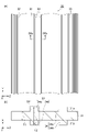
- FIG. 1 is a schematic perspective view showing a partially broken storage battery according to the embodiment.
- FIG. 2(a) is a view showing the positive electrode viewed from the first direction
- FIG. 2(b) is an enlarged cross-sectional view taken along line IIb-IIb of FIG. 2(a).
- FIG. 3 is a plan view showing the negative electrode according to the embodiment.
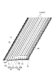
- FIG. 4(a) is a plan view showing a separator sheet
- FIG. 4(b) is a schematic cross-sectional view taken along line IVb-IVb of FIG. 4(a).
- FIG. 5 is a plan view showing a negative electrode wrapped with a separator.
- FIG. 6 is a perspective view showing a negative electrode wrapped with a separator.
- FIG. 5 is a plan view showing a negative electrode wrapped with a separator.
- FIG. 7 is an enlarged view of the main parts of the electrode plate group and the strap.
- FIG. 8 is an enlarged schematic view of a portion surrounded by a dashed line in FIGS. 5 and 6.
- FIG. 9 is a cross-sectional view taken along line IX-IX of FIG. 8.
- FIG. 10 is an enlarged cross-sectional view of main parts of a separator and a negative electrode included in an electrode group according to a modification.
- FIG. 1 is a schematic perspective view showing a partially broken storage battery according to this embodiment.
- the storage battery 1 is, for example, a lead storage battery.
- the storage battery 1 is used, for example, as a battery for an automobile, a backup power source used in the event of a power failure, and a main power source for an electric vehicle (or an electric vehicle) such as an electric forklift.
- an assembled battery composed of a plurality of storage batteries 1 may be used.
- the electric vehicle may have an assembled battery including a plurality of storage batteries 1 .
- the storage battery 1 is, for example, a clad lead-acid battery with clad electrodes.
- the storage battery 1 includes an electrode plate group 3 , a positive electrode terminal 5A, a negative electrode terminal 5B, a supplementary water tap 6 and a case 7 .
- Case 7 has main body 8 and lid 9 .
- the main body 8 is a box-shaped container.
- the main body 8 is made of a material such as polypropylene.
- the main body 8 accommodates the electrode plate group 3 and an electrolytic solution.
- the main body 8 is composed of four side portions and a bottom portion.
- a lid 9 covers the opening of the body 8 .
- the lid 9 is provided with a positive electrode terminal 5A, a negative electrode terminal 5B, and a supplementary water tap 6 .
- a supplementary water tap 6 is provided between the positive terminal 5A and the negative terminal 5B.
- the electrode plate group 3 has multiple positive electrodes 10 , multiple negative electrodes 12 , and multiple separators 13 .
- positive electrodes 10 and negative electrodes 12 are alternately arranged.
- a separator 13 is positioned between the adjacent positive electrode 10 and negative electrode 12 . Therefore, the positive electrode 10, the separator 13 and the negative electrode 12 are stacked in order in a predetermined direction.
- the negative electrode 12 is located at the end of the positive electrode 10, the negative electrode 12, and the separator 13 in the direction in which they are arranged (hereinafter sometimes simply referred to as the “arrangement direction” or the “stacking direction”). are placed.
- the assembly of the positive electrode 10, the negative electrode 12, and the separator 13 is also called a battery electrode plate group (electrode group).
- the electrode plate group 3 and the electrolyte are accommodated in the main body 8, the electrolyte exists in the gap between the positive electrode 10 and the separator 13, in the separator 13, and the like.
- first direction X A direction perpendicular to the first direction X (vertical direction) is defined as a second direction Y
- second direction Y a direction perpendicular to the first direction X and the second direction Y
- third direction Z a direction perpendicular to the first direction X and the second direction Y
- the second direction Y corresponds to the direction in which the electrode plate group 3 is housed in the case 7 .
- the first direction X, the second direction Y, and the third direction Z are orthogonal to each other, but are not limited to this.
- the first direction X, the second direction Y, and the third direction Z may intersect each other.
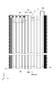
- FIG. 2 is a view showing the positive electrode viewed from the first direction
- (b) of FIG. 2 is an enlarged cross-sectional view taken along line IIb-IIb of (a) of FIG.
- the positive electrode 10 is, for example, a clad positive electrode plate (second electrode plate).
- each positive electrode 10 is electrically connected to the positive electrode terminal 5A.
- Each positive electrode 10 and the positive electrode terminal 5A are electrically connected by a positive electrode strap 17, which is a conductive member made of metal or alloy.
- the positive electrode 10 includes a current collector 14 , a plurality of tubular bodies 15 (tubes) accommodating a portion of the current collector 14 , a positive electrode material 16 accommodated in the tubular bodies 15 , and attached to the current collector 14 . an upper link 21 and a lower link 22 .
- the current collector 14 has a plurality of core metals 14a, a connecting portion (not shown) that connects the plurality of core metals 14a and is covered by the upper connecting member 21, and ears 14c that protrude from the connecting portion.
- the current collector 14 is formed, for example, by casting.
- the constituent material of the current collector 14 may be any conductive material, and examples thereof include lead-calcium-tin based alloys, lead-antimony-arsenic based alloys, and other lead alloys. Lead alloys may include selenium, silver, bismuth, and the like.
- the plurality of core bars 14a are rod-shaped portions extending along the second direction Y and arranged in a row along the third direction Z.
- One end of each cored bar 14 a in the second direction Y is connected to a connecting portion (not shown) covered by the upper connecting seat 21 .
- the other end of each cored bar 14 a in the second direction Y is fixed to the lower connecting seat 22 .
- the length of each cored bar 14a is, for example, 170 to 650 mm.
- the length of each cored bar 14a may be 600 mm or less, or may be 450 mm or less.
- the connecting portion is a portion that supports the metal core 14a and the ear portion 14c, and extends along the third direction Z. As shown in FIG.
- the connecting portion is arranged on the positive electrode terminal 5A side in the second direction Y.
- the cored bar 14 a and the connecting portion are also referred to as a body portion (second body portion) of the positive electrode 10 .
- the ear portion 14 c is a terminal portion protruding in the second direction Y from the connecting portion, and is welded to the positive electrode strap 17 positioned above the positive electrode 10 , the negative electrode 12 and the separator 13 in the second direction Y.
- the protruding direction of the ear portion 14c is opposite to the protruding direction of the cored bar 14a.
- the ear portion 14 c protrudes upward from the connecting portion and is positioned on the lid 9 side in the second direction Y.
- the plurality of cylindrical bodies 15 are insulating members that constitute a group of active material holding tubes (cladding tubes).
- the active material holding tube group is an assembly of cylindrical porous tubes, also called a "gauntlet". For this reason, each cylindrical body 15 is provided with a plurality of holes. In this embodiment, the thickness of the cylindrical body 15 is uniform, but the thickness is not limited to this.
- Each cylindrical body 15 extends along the second direction Y and accommodates the corresponding cored bar 14a.
- Each tubular body 15 is, for example, a resin molding.
- the positive electrode material 16 is filled inside the cylindrical body 15 together with the metal core 14a. Therefore, the cored bar 14 a and the positive electrode material 16 are accommodated in the cylindrical body 15 . As shown in (b) of FIG. 2 , the positive electrode material 16 surrounds the metal core 14 a inside the cylindrical body 15 .
- Cathode material 16 includes an active material. Active materials include both active materials after chemical conversion and raw materials for active materials before chemical conversion.
- the positive electrode material 16 contains an active material after chemical conversion.
- the positive electrode material 16 after chemical conversion contains, for example, a raw material of a positive electrode active material.
- the cathode material 16 may include a cathode active material and an additive.
- the positive electrode active material is, for example, lead powder, red lead, or the like. Examples of additives include carbon materials, reinforcing short fibers, and the like.
- the positive electrode active material after chemical conversion is, for example, lead dioxide.
- the upper connecting member 21 is an insulating structure attached to the connecting portion of the current collector 14 and covers the connecting portion when viewed from the second direction Y.
- the upper connecting seat 21 seals one end of each tubular body 15 in the second direction Y.
- the upper linking member 21 is welded to each cylindrical body 15, but the present invention is not limited to this.
- the upper linking seat 21 and each cylindrical body 15 may be fixed to each other, for example, via an adhesive or the like.
- the upper connecting member 21 is provided by, for example, welding an insulating resin member to the current collector 14 .
- the lower connecting seat 22 is an insulating structure attached to a plurality of metal cores 14 a of the current collector 14 .
- the lower connecting member 22 is attached to the current collector 14 by, for example, inserting and fitting the metal core 14a of the current collector 14 into an insulating resin member.
- the lower connecting seat 22 seals the other end of each tubular body 15 in the second direction Y.
- the position of each cylindrical body 15 in the positive electrode 10 is fixed by the upper connecting seat 21 and the lower connecting seat 22 .
- the lower linking seat 22 is welded to each cylindrical body 15, but the present invention is not limited to this.
- the lower linking seat 22 and each cylindrical body 15 may be fixed to each other by, for example, an adhesive or the like.
- FIG. 3 is a plan view showing the negative electrode according to the embodiment.
- the negative electrode 12 is a negative electrode plate (first electrode plate) in the storage battery 1 and is electrically connected to the negative electrode terminal 5B.
- Each negative electrode 12 and the negative electrode terminal 5B are electrically connected by a negative electrode strap 18, which is a conductive member made of metal or alloy.
- the negative electrode 12 has a current collector 12a and a negative electrode material 12b.
- the current collector 12a is formed, for example, by casting, and has a negative electrode lattice 12c and ears 12d.
- the negative electrode grid 12c is a main body (first main body) of the negative electrode 12 and holds the negative electrode material 12b.
- the thickness of the portion of the negative electrode 12 where the negative electrode material 12b is held is greater than the thickness of the negative electrode grid 12c, but is not limited to this.
- the negative electrode material 12b may contain a negative electrode active material and an additive.
- the negative electrode active material is, for example, spongy lead.
- additives include barium sulfate, carbon materials, lignin, or reinforcing short fibers.
- the ear portion 12d is a terminal portion protruding from the negative electrode grid 12c along the second direction Y, and is welded to the negative electrode strap 18 positioned above the positive electrode 10, the negative electrode 12, and the separator 13 in the second direction Y.
- the ear portion 12 d protrudes upward along the second direction Y toward the negative electrode strap 18 .
- the ear portion 12d and the negative grid 12c do not overlap each other in the first direction X.
- the negative grid 12 c is covered with the separator 13 .
- Protrusions 12e and 12f are provided on the negative electrode grid 12c.
- the convex portions 12e and 12f are leg portions that are arranged at a predetermined interval and protrude outward from the negative electrode grid 12c.
- the protrusions 12e and 12f protrude in a direction opposite to the protruding direction of the ear portion 12d.
- the projection direction of the ear portion 12d and the projection direction of the projections 12e and 12f are orthogonal to the arrangement direction.
- the ear portions 12d and the negative electrode grid bodies 12c do not overlap each other in the arrangement direction.
- the separator 13 is a battery member (battery separator) for preventing a short circuit between the positive electrode 10 and the negative electrode 12 .
- the separator 13 electrically insulates between the positive electrode 10 and the negative electrode 12 while allowing ions to pass therethrough.
- materials (materials) for such a separator 13 include glass fibers, resins, inorganic substances, and the like.
- the separator 13 is a member that wraps at least a portion of the negative electrode 12 and covers the negative electrode 12 when viewed from the first direction. More specifically, the separator 13 covers the negative electrode lattice 12c and the projections 12e and 12f of the negative electrode 12, and the tabs 12d of the negative electrode 12 are exposed from the separator 13. As shown in FIG.
- FIG. 4(a) is a plan view showing a separator sheet.
- FIG. 4(b) is a schematic cross-sectional view taken along line IVb-IVb of FIG. 4(a).
- the separator sheet 30 has a main portion 31, a pair of edge portions 32 and 33, and a plurality of ribs .
- the main part 31 is a sheet-like part that is the main part of the separator sheet 30 and exhibits flexibility.
- the main portion 31 has a first principal surface 31a and a second principal surface 31b located on the opposite side of the first principal surface 31a in the first direction X. As shown in FIG. In the present embodiment, the first main surface 31a and the second main surface 31b have a rectangular shape when viewed from the first direction X, but this is not the only option.
- the pair of edge portions 32 and 33 are portions provided at both ends of the separator sheet 30 in the third direction Z.
- Each of the edge portions 32 and 33 extends from one end of the separator sheet 30 in the second direction Y (for example, the upper end of the page in FIG. 4A) to the other end (for example, the lower end of the page in FIG. 4A). extends up to Each of the edges 32, 33 may extend continuously or intermittently.
- the edge 32 is provided at one end of the separator sheet 30 in the third direction Z (for example, the left end of the paper surface in FIG. 4A), and the edge 33 is provided at the other end of the separator sheet 30 in the third direction Z (for example, It is provided on the right side of the paper surface in (a) of FIG.
- ribs different from the ribs 34 are provided on the pair of edge portions 32 and 33 .
- one or a plurality of ribs or the like extending from one end of the separator sheet 30 in the second direction Y to the other end may be provided on each of the pair of edge portions 32 and 33 .
- the plurality of ribs 34 are provided, for example, to improve the durability of the separator sheet 30 and improve the fluidity of the electrolytic solution in the case 7.
- a plurality of ribs 34 protrude from the main portion 31 along the first direction X and are spaced apart from each other.
- Each of the plurality of ribs 34 has a rectangular shape when viewed from the first direction X. As shown in FIG.
- Each of the plurality of ribs 34 extends from one end to the other end of the separator sheet 30 in the second direction Y and extends parallel to each other.
- the cross section of the rib 34 perpendicular to the extending direction of the rib 34 has a rectangular shape, but is not limited to this.
- the cross section may be, for example, trapezoidal or inverted trapezoidal.
- the dimension (width) of the ribs 34 along the third direction Z is 0.30% or more and 2.5% or less of the dimension of the separator sheet 30 along the third direction Z, for example.
- the dimension (height) of the rib 34 along the first direction X is, for example, greater than 100% and 1000% or less of the dimension (thickness) of the main portion 31 along the first direction X.
- the ribs 34 have a plurality of first ribs 34a provided on the first main surface 31a and a plurality of second ribs 34b provided on the second main surface 31b.
- the first rib 34a protrudes along the first direction X from the first major surface 31a.
- the second rib 34b protrudes from the second main surface 31b to the side opposite to the first rib 34a.
- the first rib 34a and the second rib 34b have the same shape and completely overlap each other.
- the portion of the separator sheet 30 where the ribs 34 are provided is also referred to as a thick portion TP1 of the separator sheet 30 (and the separator 13).
- the portion where the main portion 31 and the rib 34 overlap each other is also called a thick portion TP1. Therefore, the thick portion TP1 has ribs 34 .
- the thickness of the thick portion TP1 in this embodiment is equal to the thickness of the main portion 31 and the thickness of the first rib 34a. It corresponds to the sum of the height and the height of the second rib 34b.
- the second thickness T2 is, for example, greater than 100% of the first thickness T1. 2000% or less.
- FIG. 5 is a plan view showing a negative electrode wrapped with a separator.
- FIG. 6 is a perspective view showing a negative electrode wrapped with a separator.
- FIG. 7 is an enlarged view of the main parts of the electrode plate group and the strap.
- the separator 13 corresponds to a separator sheet bag-like processed product, and wraps the negative electrode 12 .
- the ear portion 12 d of the negative electrode 12 is exposed from the separator 13 , and the convex portions 12 e and 12 f of the negative electrode 12 are covered with the separator 13 .
- the separator 13 is formed by, for example, folding one separator sheet 30 in two along the second direction Y and then sealing desired portions. At this time, the separator sheet 30 is folded back on the side of the projections 12 e and 12 f of the negative electrode 12 in the second direction Y so that the negative electrode 12 is sandwiched between the separator sheets 30 .
- the separator sheet 30 may be folded in half as the negative electrode 12 moves.
- the aspect ratio between the dimension of the separator 13 along the second direction Y and the dimension of the separator 13 along the third direction Z is, for example, 1.4 or more and 4.0 or less.
- the aspect ratio may be 1.5 or more and 3.8 or less, 1.8 or more and 3.5 or less, or 2.0 or more and 3.0 or less.
- the separator 13 has a base portion 41 , a pair of seal portions 42 and 43 , a bent portion 44 and a joint portion 45 .
- the base portion 41 is a portion that accommodates the negative electrode grid 12c of the negative electrode 12 .
- the base portion 41 is composed of the main portion 31 of the separator sheet 30 and the edge portions 32, 33 (see FIG. 4(a)). Therefore, the base 41 has a first main surface 31a provided with the first ribs 34a and a second main surface 31b provided with the second ribs 34b (see (b) of FIG. 4).
- the first principal surface 31a faces the negative electrode 12, and the second principal surface 31b is an exposed surface. Therefore, the positive electrode 10 (see FIG. 1) in the electrode plate group 3 faces the second main surface 31 b of the separator sheet 30 .
- the portion of the base portion 41 that overlaps the negative electrode 12 in the first direction X is referred to as an inner portion 41a.
- a portion of the base portion 41 located outside the inner portion 41a as viewed from the first direction X is referred to as an outer portion 41b.
- the boundary between the inner portion 41a and the outer portion 41b abuts, for example, the outer edge of the negative grid 12c.
- the inner portion 41a includes a portion of the main portion 31 and a portion of the edges 32,33
- the outer portion 41b includes another portion of the main portion 31 and another portion of the edges 32,33. including the part.
- the base portion 41 is formed by folding the separator sheet 30 in half so that the second main surface 31b is the outer surface.
- the base portion 41 includes a first main portion 51 located on one end side in the first direction X and a second main portion 51 located on the other end side in the first direction X relative to the first main portion 51 . and a portion 52 .
- it is a part of the first main portion 51, constitutes the outer portion 41b, and is located on the opposite side of the bent portion 44 in the second direction Y via the negative electrode grid 12c.
- the part which carries out is the edge part 51a (1st edge part).
- a portion of the second main portion 52 which constitutes the outer portion 41b and which is located on the opposite side of the bent portion 44 in the second direction Y with the negative electrode lattice 12c interposed therebetween, is an end portion 52a (second 2 ends).
- An end portion 13a of the separator 13 is formed by the end portions 51a and 52a. The end portion 13a becomes the upper end portion of the separator 13 when the separator 13 is accommodated in the case 7 (see also FIG. 9 described later).
- the pair of seal portions 42 and 43 are portions for maintaining the state in which the separator sheet 30 is folded in two, and are provided on the outer portion 41b.
- the seal portion 42 is formed on the edge portion 32 (see FIG. 4(a)), and the seal portion 43 is formed on the edge portion 33 (see FIG. 4(a)).
- Each of the seal portions 42 and 43 is positioned outside the negative electrode 12 in the third direction Z. As shown in FIG.
- Each of the seal portions 42 and 43 extends in the second direction Y. As shown in FIG. Thereby, movement of the negative electrode 12 along the third direction Z can be suppressed by the seal portions 42 and 43 .
- the seal portions 42 and 43 may not be completely sealed.
- each of the seal portions 42 and 43 may be provided with a region through which the electrolyte can pass.
- the seal portions 42 and 43 are, for example, an ultrasonic weld portion, a heat seal portion, a cold seal portion, a gear seal portion, or the like.
- the gear seal portion is a portion that is mechanically bonded by pressure using a gear.
- each of the seal portions 42 and 43 is a gear seal portion that extends from one end of the separator 13 in the second direction Y to the other end.
- the bent portion 44 is a portion where the separator 13 is folded back, and is provided on the outer portion 41b. At least part of the bent portion 44 can abut on the negative electrode grid 12c. A part of the bent portion 44 is provided with an opening 44a.
- the opening 44a is a portion provided, for example, to improve fluidity of the electrolytic solution within the separator 13 .
- the opening 44a is provided, for example, in the central portion of the separator 13 in the third direction Z, but is not limited to this.
- the opening 44a is formed by cutting a portion of the bent portion 44 .
- the bent portion 44 is located below the negative electrode 12 in the second direction Y when the separator 13 enclosing the negative electrode 12 is accommodated in the case 7 . Accordingly, when the separator 13 moves upward relative to the negative electrode 12, the bent portion 44 functions as a restricting portion that restricts the upward movement.
- the joint portion 45 is a portion for maintaining the state of the separator sheet 30 folded in half, similar to the seal portions 42 and 43 .
- the joint portion 45 is a portion that joins the end portion 51 a of the first main portion 51 and the end portion 52 a of the second main portion 52 .
- the joint portion 45 is an upper joint portion that joins the first main portion 51 and the second main portion 52 above the negative electrode grid 12c in the second direction Y, and Included in part 13a.
- the joint portion 45 faces the negative electrode grid 12c of the negative electrode 12 in the second direction Y and faces the ear portion 12d in the third direction Z. As shown in FIG.
- the joint portion 45 extends along the third direction Z. As shown in FIG.
- the joint portion 45 extends from one end of the separator 13 toward the other end in the third direction Z, and is provided at the base portion 41 and the seal portion 42 . That is, part of the joint portion 45 overlaps the seal portion 42 .
- the joint portion 45 is, for example, a portion where the separator sheet 30 itself is welded. In this case, a part of the first main surface 31a and another part are welded together at the joint portion 45 . From the viewpoint of preventing welding failure, the joint portion 45 may be formed by ultrasonic welding or the like.
- the joint portion 45 may be provided after the seal portions 42 and 43 are formed, or may be provided before the seal portions 42 and 43 are formed.
- the joint portion 45 overlaps the ear portion 14c of the positive electrode 10 in the first direction X.
- both ends of the joint portion 45 in the third direction Z when viewed from the first direction X are located outside the ears 14c. Therefore, the dimension of the joint portion 45 in the third direction Z is greater than or equal to the dimension of the ear portion 14c in the third direction Z.
- the joint portion 45 is positioned below the positive electrode strap 17 in the second direction Y. As shown in FIG. Therefore, when the electrode plate group 3 is accommodated in the case 7 , the joint portion 45 is positioned between the negative grid 12 c and the positive strap 17 in the second direction Y. As shown in FIG.
- an opening O is defined by the ends 51a, 52a.
- the opening O is a portion for exposing the ear portion 12 d from the separator 13 .
- the outside portion 41 b of the separator 13 is provided with a bent piece 61 and a closing portion 62 .
- the bending piece 61 is the outer portion 41b and is a portion provided by a part of each of the end portion 51a and the end portion 52a.
- the bending piece 61 is provided at least between the negative electrode lattice 12c and the positive electrode strap 17 in the second direction Y in the end portion 13a of the separator 13 . Therefore, when the electrode plate group 3 is accommodated in the case 7, the portion of the end portion 13a where the bent piece 61 is provided (that is, the portion above the negative electrode lattice 12c in the second direction Y and the positive electrode strap) 17) is drooping.
- the ends 13a of the separators 13 are provided with bent pieces 61, and the directions in which the ends 13a hang down are aligned.
- the bending piece 61 includes the joint portion 45 .
- FIG. 8 is an enlarged schematic view of a portion surrounded by a dashed line in FIGS. 5 and 6.
- FIG. 9 is a cross-sectional view taken along line IX-IX of FIG. 8.
- the bending piece 61 has a proximal end portion 71, an inflection portion 72, and a distal end portion 73 arranged in order in the second direction Y.
- a base end portion 71 of the bent piece 61 is the portion closest to the negative electrode grid 12c in the second direction Y.
- FIG. 8 is an enlarged schematic view of a portion surrounded by a dashed line in FIGS. 5 and 6.
- FIG. 9 is a cross-sectional view taken along line IX-IX of FIG. 8.
- FIG. 8 and 9 the bending piece 61 has a proximal end portion 71, an inflection portion 72, and a distal end portion 73 arranged in order in the second direction Y.
- the tip portion 73 of the bent piece 61 is the farthest portion in the second direction Y from the negative grid 12c.
- the bent portion 72 is located closer to the positive electrode strap 17 than the base end portion 71 in the second direction Y, and the tip portion 73 is bent in the second direction Y. It is located closer to the positive electrode strap 17 than the portion 72 is.
- the bending piece 61 curves so as to draw a J-shape or a U-shape when viewed from the third direction Z, for example.
- the base end portion 71 is a portion extending along the second direction Y. In the present embodiment, the base end portion 71 is closer to the tip portion 73 than the boundary BD between the inner portion 41a and the outer portion 41b in the second direction Y, and closer to the negative grid 12c than the joint portion 45. .
- the inflection portion 72 is a portion including an inflection point of the bending piece 61 and is located between the proximal end portion 71 and the distal end portion 73 in the second direction Y. As shown in FIG. Note that the base end portion 71 does not necessarily have to extend completely along the second direction Y.
- the proximal end portion 71 may extend along the second direction Y at least more than the distal end portion 73 . In other words, the angle formed by the straight line along the second direction Y and the proximal portion 71 should be smaller than the angle formed by the straight line and the distal portion 73 .
- the inflection portion 72 is a boundary point between the proximal end portion 71 and the distal end portion 73 in the second direction Y, and is provided along one end of the joint portion 45 along the second direction Y. In the present embodiment, it is provided along the portion of the joint 45 that is closest to the negative grid 12c in the second direction Y. As shown in FIG. This portion corresponds to the lower end 45 a of the joint portion 45 when the electrode plate group 3 is accommodated in the case 7 .
- the tip portion 73 is a free end extending from the bent portion 72 and is the furthest from the negative electrode 12 in the bent piece 61 . The tip portion 73 extends from the other side of the negative electrode 12 in the first direction X toward one side.
- An angle ⁇ 1 formed between the proximal end portion 71 and the distal end portion 73 of the inflection portion 72 is, for example, less than 180°.
- the tip portion 73 is positioned closer to the negative grid 12c in the second direction Y than when the angle ⁇ 1 is 180°.
- the angle ⁇ 1 may be 170° or less, 160° or less, 150° or less, 60° or more, 70° or more, 80° or more, or 90° or more. good.
- the angle ⁇ 1 may be 120° or more, 130° or more, or 140° or more.
- the joint 45 is included in the tip portion 73 .
- a corner portion 12g located on one side of the negative electrode 12 in the first direction X and a corner portion located on the other side of the negative electrode 12 in the first direction X A separator 13 is in contact with each of 12h.
- the corners 12g and 12h face the end 13a of the separator 13 in the second direction Y, respectively. Since the main portion 31 of the separator 13 exhibits flexibility as described above, the separator 13 may be bent at at least one of the corner portions 12g and 12h in the storage battery 1 . From the viewpoint of preventing breakage of the separator 13, each of the corners 12g and 12h may be chamfered.
- each of the corners 12g and 12h may be rounded, for example.
- Each of the corners 12g and 12h may be chamfered after the formation of the negative electrode 12, but is not limited to this.
- the corners 12g and 12h can have a shape such as a round surface without the chamfering process.
- the first ribs 34a are in contact with the corners 12g and 12h, respectively.
- the closure portion 62 is located between the ear portion 12d and the joint portion 45 in the third direction Z, and is located between the first main portion 51 and the second main portion 52 in the outer portion 41b. and are in contact with each other.
- the closure 62 is caused by the deformation of the outer portion 41 b that accompanies the formation of the joint 45 . Due to such influence, the contact between the first main portion 51 and the second main portion 52 in the closing portion 62 is maintained. Therefore, in the present embodiment, at least a portion of the end portions 51a and 52a closer to the ear portion 12d than the joint portion 45 in the third direction Z is closed.
- the separator sheet 30 and the negative electrode 12 are prepared. At this time, the first main surface 31a of the separator sheet 30 and the negative electrode 12 are opposed to each other. Subsequently, by folding the separator sheet 30 in two, the bent portion 44 is formed and the first main portion 51 and the second main portion 52 are opposed to each other in the first direction X (first step). At this time, the negative electrode 12 is sandwiched between the separator sheets 30 by folding the separator sheets 30 in two. That is, the negative electrode 12 is arranged in the first direction X between the first main portion 51 and the second main portion 52 . As a result, the negative electrode lattice 12c of the negative electrode 12 is completely covered with the first main surface 31a of the separator sheet 30, and part of the ear portion 12d of the negative electrode 12 is exposed from the separator sheet 30. As shown in FIG.
- the seal portion 42 is formed on the separator sheet 30 with the negative electrode 12 arranged between the first main portion 51 and the second main portion 52 .
- one end portion of the first main portion 51 and one end portion of the second main portion 52 in the third direction Z are joined along the second direction Y to form the seal portion 42 .
- the seal portion 42 is formed by processing the one ends with a gear seal device.
- the separator sheet 30 (specifically, the other end of the first main portion 51 and the other end of the second main portion 52 in the third direction Z) is formed by a method similar to the method of forming the seal portion 42 .
- a seal portion 43 is formed.
- the joint portion 45 is formed on the separator sheet 30 while the negative electrode 12 is still arranged between the first main portion 51 and the second main portion 52 (second step).
- the joint portion 45 is formed by joining the end portion 51a of the first main portion 51 and the end portion 52a of the second main portion 52 along the third direction Z.
- a bending piece 61 having a bending portion 72 at the lower end 45a of the joint portion 45 and a closing portion 62 are formed.
- the joint 45 is formed by, for example, ultrasonic welding using an ultrasonic welding device including a horn.
- the separator 13 enclosing the negative electrode 12 is formed.
- a plurality of positive electrodes 10 and a plurality of negative electrodes 12 wrapped in separators 13 are prepared. Subsequently, the positive electrode 10 and the negative electrode 12 wrapped with the separator 13 are alternately laminated. At this time, the positive electrode 10 , the separator 13 , and the negative electrode 12 are stacked in the first direction X so that the ribs 34 and the cylindrical body 15 are stacked in the thickness direction of the separator 13 . Subsequently, the positive electrode strap 17 is welded to the ear portion 14c of the positive electrode 10, and the negative electrode strap 18 is welded to the ear portion 12d of the negative electrode 12 (third step).
- each positive electrode 10 and the positive strap 17 are electrically connected, and each negative electrode 12 and the negative strap 18 are electrically connected.
- the joint portion 45 and the bent piece 61 included in the end portion 13a of the separator 13 are positioned between the negative electrode grid 12c and the positive electrode strap 17 in the second direction Y.
- the electrode plate group 3 including the plurality of positive electrodes 10, the plurality of negative electrodes 12, and the plurality of separators 13 is formed.
- the electrode plate group 3 is accommodated in the main body 8 .
- the main body 8 is then sealed with the lid 9 .
- each positive electrode 10 is electrically connected to the positive electrode terminal 5A
- each negative electrode 12 is electrically connected to the negative electrode terminal 5B.
- the electrolytic solution is supplied into the case 7 via the replenishment tap 6 . Thereby, the storage battery 1 is manufactured.
- the ends 13a of the separators 13 located between the negative grid 12c and the positive strap 17 are arranged in the second direction. It has a proximal portion 71, an inflection portion 72, and a distal portion 73 positioned in sequence at Y, and the angle between the proximal portion 71 and the distal portion 73 in the inflection portion 72 is less than 180°.
- the distance between the portion where the positive electrode strap 17 and the ear portion 14c of the negative electrode 12 are welded and the end portion 13a of the separator 13 is reduced. Intervals can be increased. Therefore, according to the present embodiment, it is possible to suppress breakage of the separator 13 when the positive electrode strap 17 and the negative electrode 12 are welded together, compared to the case where the bent portion 72 is not provided at the end portion 13a of the separator 13 .
- the short circuit between the positive electrode 10 and the negative electrode 12 that overlap each other with the separator 13 interposed therebetween can be suppressed satisfactorily.
- the separator 13 has a first main portion 51 located on one end side in the first direction X and a second main portion 52 located on the other end side in the first direction X relative to the first main portion 51 . , and a joint portion 45 that joins the first main portion 51 and the second main portion 52 above the negative electrode grid 12 c in the second direction Y, and the end portion 13 a includes the joint portion 45 .
- the end portion 13a of the separator 13 tends to sag compared to the case where the joint portion 45 is not provided on the separator 13 .
- the negative electrode 12 has ears 12d that protrude upward from the negative electrode grid 12c in the second direction Y and are exposed from the openings O of the separator 13.
- a closing portion 62 is provided between the portion 12d and the first main portion 51 and the second main portion 52, and the contact between the first main portion 51 and the second main portion 52 in the closing portion 62 is , is maintained by the influence of the deformation of the first main portion 51 and the second main portion 52 due to the formation of the joint portion 45 . Therefore, the opening O of the separator 13 can be reduced without enlarging the joint 45 . Therefore, it is possible to prevent the negative electrode material 12b of the negative electrode 12 from flowing out of the separator 13 while suppressing the damage to the separator 13 due to the formation of the joint portion 45 .
- the joint 45 is positioned between the negative grid 12c and the positive electrode strap 17 in the second direction Y, and the bent portion 72 of the separator 13 is provided at the lower end 45a of the joint 45. Therefore, the end portion 13a of the separator 13 can be reliably hung.
- the electrode plate group 3 includes a plurality of positive electrodes 10, a plurality of negative electrodes 12, and a plurality of separators 13, and the ears 14c included in each of the plurality of positive electrodes 10 are welded to the positive electrode strap 17.
- the direction in which the ends 13a hang down may be the same. In this case, the plurality of separators 13 are less likely to break when the positive electrode strap 17 and each positive electrode 10 are welded.
- the separator 13 is provided with at least one first rib 34a. , 12h. Therefore, breakage of the portions of the separator 13 that contact the corners 12g and 12h can be suppressed.
- the separator 13 is positioned below the negative electrode grid 12c in the second direction Y and has a regulating portion that regulates the upward movement of the separator 13. including portion 44; Therefore, it is possible to easily form a restricting portion that restricts the separator 13 from rising and approaching the positive electrode strap 17 .
- the bending piece 61 is formed along with the formation of the joint portion 45 . Therefore, the bending piece 61 can be formed without increasing the manufacturing process of the separator 13 .
- FIG. 10 is an enlarged cross-sectional view of main parts of a separator and a negative electrode included in an electrode group according to a modification.
- the shape of the bent piece 61A of the separator 13A is different from the shape of the bent piece 61 of the above embodiment.
- the position of the inflection portion 72A of the bending piece 61A according to the modification is provided along the farthest portion of the joint portion 45 from the negative electrode grid 12c in the second direction Y.
- This portion corresponds to the upper end 45 b of the joint portion 45 when the electrode plate group 3 is accommodated in the case 7 .
- the joint 45 is included in the proximal portion 71 .
- the range of the angle ⁇ 2 formed by the base end portion 71 and the tip end portion 73 of the inflection portion 72A is the same as the angle ⁇ 1 of the above embodiment.
- the modified example described above can also achieve the same effects as the above-described embodiment.
- the battery electrode group and the like according to one aspect of the present disclosure are not limited to the above embodiment and modification.
- the inflection portion of the bending piece is provided at the lower end of the joint portion, and according to the above modification, the inflection portion of the bending piece is provided at the upper end of the joint portion, but the present invention is not limited to this.
- inflection portions may be provided at both the upper and lower ends of the joint. In this case, the tip portion can be brought closer to the negative grid side in the second direction.
- the sum of the two angles is, for example, 240° or more, 260° or more, 280° or more. ° or more, 300° or more, 310° or more, or 320° or more.
- the ribs extend linearly when viewed from the first direction, but the present invention is not limited to this.
- the ribs when viewed from the first direction, may extend in a wavy line shape or in a zigzag shape.
- the ribs may be point-shaped (dot-shaped), circular, elliptical, or polygonal when viewed from the first direction.
- the ribs may have a polygonal pyramid shape, a polygonal truncated pyramid shape, a conical shape, or a truncated cone shape.
- the cross section of the rib may be semicircular or polygonal.
- the ribs may extend along the second direction or along the third direction.
- the thick portion includes ribs in the above embodiment and modification, the present invention is not limited to this.
- the thick portion may be any portion thicker than the thinnest portion of the separator, and may not include ribs.
- the separator may have both a thick portion with ribs and a thick portion without ribs.
- the ribs protrude from both the first main surface and the second main surface in the above embodiment and modification, the present invention is not limited to this.
- the ribs may protrude only from the first main surface, or the ribs may protrude only from the second main surface.
- the separator sheet is folded in two along the third direction in the above-described embodiment and modified example, it is not limited to this.
- the separator sheet may be folded in two along the second direction. In this case, the bent portion of the separator may not have an opening.
- the separator is a bag-like processed product in the above embodiment and each modification, it is not limited to this.
- the separator may be a tubular workpiece.
- the seal portions may be provided on both sides in the third direction, or may be provided only on one side in the third direction.
- the joint portion may be provided only on the opposite side of the ear portion of the negative electrode with the negative electrode grid interposed therebetween in the second direction.
- the separator is formed from one separator sheet in the above embodiment and modification, the present invention is not limited to this.
- the separator may be formed from multiple separator sheets.
- the seal portions may be formed on both end sides of the separator in the third direction, or may be formed only on one side in the third direction.
- the joint portions are formed on both sides of the separator in the second direction, the present invention is not limited to this.
- the joint may be formed only on one side in the second direction. Therefore, when the separator is formed from a plurality of separator sheets, the separator may be a bag-shaped processed product, a cylindrical processed product, or a processed product different from the bag-shaped processed product and the cylindrical processed product. good.
- the separator When the separator is formed from a plurality of separator sheets, the separator need not be provided with a bent portion of the separator sheet.
- a joint portion may be provided that is located on the opposite side of the ear portion of the negative electrode with the negative electrode grid interposed therebetween in the second direction.
- the joint functions as a lower joint located between the negative electrode and the lower end of the separator in the second direction when the electrode group is accommodated in the case.
- the joint portion also functions as a restricting portion that restricts the separator from rising, instead of the bent portion provided in the above embodiment and the above modified example. It is preferable that the joint portion is provided so as to face the convex portion of the negative electrode in the second direction.
- the protrusions are less likely to be exposed from the separator, short circuits are less likely to occur.
- the joint is provided so as to face the protrusion of the negative electrode in the second direction, it is more preferable that the dimension of the joint along the third direction is larger than the dimension of the protrusion along the third direction. In this case, it becomes difficult for the protrusions to be well exposed from the separator.
- the battery case includes a plurality of separators, but is not limited to this.
- the container may contain a separator composed of a single separator sheet.
- the plurality of positive electrodes and the plurality of negative electrodes included in the electrode group are separated by one sheet of separator sheet that is folded in a bellows shape in the arrangement direction.
- the positive electrode is arranged so as to be sandwiched between the first main surfaces of the accordion-shaped separator sheet
- the negative electrode is arranged so as to be sandwiched between the second main surfaces of the separator sheet.
- Each of the negative electrode grid bodies included in the plurality of negative electrodes is covered with a separator when viewed from the first direction.
- the joint portion By providing the joint portion in a part of the separator, displacement between the separator and the positive electrode and the negative electrode can be suppressed.
- a plurality of joints When a plurality of joints are formed in the separator, a plurality of bent pieces may be formed along with the formation of the joints. In this case, it is preferable that the directions in which the plurality of ends included in the separator hang down are aligned.
Landscapes
- Chemical & Material Sciences (AREA)
- Chemical Kinetics & Catalysis (AREA)
- Electrochemistry (AREA)
- General Chemical & Material Sciences (AREA)
- Engineering & Computer Science (AREA)
- Manufacturing & Machinery (AREA)
- Secondary Cells (AREA)
Abstract
This electrode plate group is provided with: a first electrode plate and a second electrode plate, which overlap with each other in the stacking direction; a separator which covers at least a part of the first electrode plate when viewed from the stacking direction; and a strap which is arranged above the separator in the vertical direction that intersects with the stacking direction, while being electrically connected to the second electrode plate. The first electrode plate has a first main body part; the second electrode plate has a second main body part and a lug part that protrudes upward from the second main body in the vertical direction, while being welded to the strap; and the upper end part of the separator hangs down, while being positioned above the first main body and below the strap in the vertical direction.
Description
本開示は、電池用極板群、蓄電池、組電池、電動車、電池用セパレータ、電池用セパレータの製造方法、及び、電池用極板群の製造方法に関する。
The present disclosure relates to a battery electrode plate group, a storage battery, an assembled battery, an electric vehicle, a battery separator, a method for manufacturing a battery separator, and a method for manufacturing a battery electrode plate group.
電池には、正極と負極との短絡を防止するためのセパレータが用いられる。例えば、下記特許文献1には、鉛蓄電池用の袋セパレータ入り電極板の製造方法が開示される。下記特許文献1においては、セパレータを折り曲げることによって、負極板が挟み込まれる。加えて、複数箇所の溶着部分がセパレータに形成されることによって、負極板を収容する袋状のセパレータが設けられる。負極板を収容する袋状のセパレータと正極板とが積層されることによって、蓄電池が形成される。
Batteries use separators to prevent short circuits between the positive and negative electrodes. For example, Patent Literature 1 below discloses a method for manufacturing an electrode plate containing a bag separator for a lead-acid battery. In Patent Document 1 below, the negative electrode plate is sandwiched by folding the separator. In addition, by forming a plurality of welded portions on the separator, a bag-like separator for accommodating the negative electrode plate is provided. A storage battery is formed by stacking a bag-shaped separator that accommodates a negative electrode plate and a positive electrode plate.
上記特許文献1では、負極板の耳部は、セパレータから露出している。当該耳部は、他の負極板と電気的に接続するための部分であり、通常、ストラップと呼称される導電部材に溶接される。ここで、耳部と導電部材とを溶接するとき、当該耳部の周辺に位置するセパレータの端部がダメージを受け、破損してしまうおそれがある。
In Patent Document 1, the ears of the negative electrode plate are exposed from the separator. The ear portion is a portion for electrically connecting to another negative electrode plate, and is usually welded to a conductive member called a strap. Here, when the ears and the conductive member are welded, there is a risk that the ends of the separator located around the ears will be damaged and broken.
本開示の一側面の目的は、ストラップと極板との溶接時におけるセパレータの破損抑制が可能な電池用極板群、蓄電池、組電池、電動車、電池用セパレータ、電池用セパレータの製造方法、及び、電池用極板群の製造方法の提供である。
An object of one aspect of the present disclosure is to provide a battery electrode plate group, a storage battery, an assembled battery, an electric vehicle, a battery separator, a method for manufacturing a battery separator, which can suppress breakage of the separator when the strap and the electrode plate are welded together, Another object of the present invention is to provide a method for manufacturing an electrode plate group for a battery.
本開示の一側面に係る電池用極板群は、積層方向において互いに重なる第1極板及び第2極板と、積層方向から見て第1極板の少なくとも一部を覆うセパレータと、積層方向に交差する上下方向において、セパレータよりも上側に配置されると共に第2極板に電気的に接続されるストラップと、を備え、第1極板は、第1本体部を有し、第2極板は、第2本体部と、上下方向において第2本体部から上側に突出すると共にストラップに溶接される耳部とを有し、上下方向において第1本体部よりも上側であって、ストラップの下方に位置するセパレータの上端部は、垂れている。
A battery electrode plate group according to one aspect of the present disclosure includes a first electrode plate and a second electrode plate that overlap each other in the stacking direction, a separator that covers at least part of the first electrode plate when viewed from the stacking direction, and a strap disposed above the separator and electrically connected to the second electrode plate in a vertical direction intersecting the The plate has a second body portion and an ear portion that protrudes upward from the second body portion in the vertical direction and is welded to the strap. The upper end of the lower separator hangs down.
本開示の一側面に係る電池用極板群では、上下方向において第1本体部よりも上側であって、ストラップの下方に位置するセパレータの上端部は、垂れている。これにより、セパレータの上端部が垂れていない場合と比較して、ストラップと第2極板の耳部とが溶接される箇所と、ストラップの上端部との間隔を広げられる。したがって本開示の一側面によれば、セパレータの上端部が垂れていない場合と比較して、ストラップと極板との溶接時におけるセパレータの破損抑制が可能である。
In the battery electrode plate group according to one aspect of the present disclosure, the upper end portion of the separator, which is positioned above the first main body portion in the vertical direction and below the strap, hangs down. As a result, the distance between the strap's upper end and the portion where the strap and the ear of the second electrode plate are welded can be increased compared to when the separator's upper end does not droop. Therefore, according to one aspect of the present disclosure, it is possible to suppress breakage of the separator when the strap and the electrode plate are welded, compared to the case where the upper end portion of the separator does not hang down.
セパレータは、積層方向における一端側に位置する第1主部と、第1主部よりも積層方向における他端側に位置する第2主部と、上下方向において第1本体部よりも上側にて第1主部及び第2主部を接合する上側接合部と、を有し、上端部は、上側接合部を含んでもよい。この場合、セパレータに上側接合部が設けられない場合と比較して、セパレータの上端部が垂れやすくなる。
The separator has a first main portion located on one end side in the stacking direction, a second main portion located on the other end side in the stacking direction relative to the first main portion, and a separator above the first main portion in the vertical direction. and an upper joint joining the first main section and the second main section, wherein the upper end may include the upper joint. In this case, the upper end portion of the separator tends to sag compared to the case where the separator is not provided with the upper joint portion.
第1極板は、上下方向において第1本体部から上側に突出すると共にセパレータの開口部から露出する別の耳部を有し、積層方向及び上下方向に直交する方向における上側接合部と別の耳部との間には、第1主部と第2主部とが互いに接触する閉鎖部が設けられ、閉鎖部における第1主部と第2主部との接触は、上側接合部の形成に伴う第1主部と第2主部との変形の影響によって維持されてもよい。この場合、接合部を拡大することなくセパレータの開口部を縮小できる。このため、接合部の形成に伴うセパレータへのダメージを抑えつつ、第1極板の活物質がセパレータの外に流出することを抑制できる。
The first electrode plate protrudes upward from the first main body in the vertical direction and has another ear portion exposed from the opening of the separator, and is separate from the upper joint portion in the direction orthogonal to the stacking direction and the vertical direction. A closure is provided between the ear and the first and second bodies contacting each other, and the contact of the first and second bodies at the closure forms an upper joint. may be maintained by the influence of the deformation of the first main portion and the second main portion accompanying the . In this case, the opening of the separator can be reduced without enlarging the joint. Therefore, it is possible to prevent the active material of the first electrode plate from flowing out of the separator while suppressing the damage to the separator due to the formation of the joint.
上側接合部は、上下方向において第1本体部とストラップとの間に位置し、上側接合部の上端及び下端の少なくとも一つには、セパレータの変曲部分が設けられてもよい。この場合、セパレータの上端部を確実に垂れさせることができる。
The upper joint portion may be positioned between the first body portion and the strap in the vertical direction, and at least one of the upper end and the lower end of the upper joint portion may be provided with an inflection portion of the separator. In this case, the upper end portion of the separator can be reliably hung.
上記電池用極板群は、複数の第1極板と、複数の第2極板と、複数のセパレータとを備え、複数の第2極板のそれぞれに含まれる耳部は、ストラップに溶接されており、複数のセパレータのそれぞれにおいて、上端部が垂れる方向は、揃ってもよい。この場合、ストラップと各第2極板との溶接時に複数のセパレータが破損しにくくなる。
The battery electrode plate group includes a plurality of first electrode plates, a plurality of second electrode plates, and a plurality of separators, and an ear portion included in each of the plurality of second electrode plates is welded to the strap. In each of the plurality of separators, the direction in which the upper end portion hangs down may be the same. In this case, the separators are less likely to break when the strap and the second electrode plates are welded together.
上記電池用極板群は、複数の第1極板と、複数の第2極板とを備え、複数の第2極板のそれぞれに含まれる耳部は、ストラップに溶接されており、複数の第1極板のそれぞれに含まれる第1本体部は、積層方向から見てセパレータによって覆われており、セパレータに含まれる複数の上端部が垂れる方向は、揃っていもよい。この場合、ストラップと各第2極板との溶接時に複数の上端部が破損しにくくなる。
The battery electrode plate group includes a plurality of first electrode plates and a plurality of second electrode plates, and the ear portion included in each of the plurality of second electrode plates is welded to the strap. The first body portion included in each of the first electrode plates may be covered with the separator when viewed from the stacking direction, and the directions in which the plurality of upper end portions included in the separator hang down may be aligned. In this case, the plurality of upper end portions are less likely to break when the strap and the second pole plates are welded together.
セパレータには、少なくとも一つのリブが設けられ、リブは、上下方向においてセパレータの上端部に対向する第1本体部の角部に当接してもよい。この場合、セパレータにおいて第1本体部の角部に当接する部分の破損を抑制できる。
The separator is provided with at least one rib, and the rib may abut on a corner of the first main body facing the upper end of the separator in the vertical direction. In this case, breakage of the portion of the separator that contacts the corner of the first main body can be suppressed.
セパレータは、上下方向において第1本体部よりも下側に位置し、セパレータの上昇を規制する規制部を有してもよい。この場合、セパレータが上昇してストラップに接近することを規制できる。
The separator may have a regulating portion positioned below the first body portion in the vertical direction and regulating the rising of the separator. In this case, it is possible to restrict the separator from rising and approaching the strap.
規制部は、セパレータの折り返される屈曲部を含んでもよい。この場合、セパレータに規制部を容易に形成できる。
The restricting portion may include a bent portion where the separator is folded back. In this case, the restricting portion can be easily formed in the separator.
規制部は、上下方向において第1本体部とセパレータの下端との間に位置し、セパレータの一部と他部とを接合する下側接合部を有してもよい。この場合、所望の位置に規制部が設けられる。
The restricting portion may have a lower joining portion that is positioned between the first body portion and the lower end of the separator in the vertical direction and joins a portion of the separator to the other portion. In this case, a restricting portion is provided at a desired position.
本開示の一側面に係る蓄電池は、上記電池用極板群と、当該電池用極板群を収容する電槽と、を備える。この蓄電池は、ストラップと極板との溶接時におけるセパレータの破損抑制が可能な電池用極板群を備える。このため、例えばセパレータの破損箇所が、第1極板と第2極板との短絡経路になることを良好に抑制できる。このため、当該蓄電池において、電池用セパレータを介して互いに重なる第1極板と第2極板との短絡を良好に抑制可能である。
A storage battery according to one aspect of the present disclosure includes the above-described battery electrode plate group and a container that houses the battery electrode plate group. This storage battery includes a battery electrode plate group capable of suppressing breakage of the separator when the strap and the electrode plate are welded. Therefore, for example, it is possible to satisfactorily prevent a damaged portion of the separator from becoming a short-circuit path between the first electrode plate and the second electrode plate. Therefore, in the storage battery, it is possible to satisfactorily suppress short circuits between the first electrode plate and the second electrode plate that overlap each other with the battery separator interposed therebetween.
本開示の一側面に係る組電池は、上記蓄電池を備える。この組電池は、ストラップと極板との溶接時におけるセパレータの破損抑制が可能な電池用極板群を含む蓄電池を備える。このため、当該蓄電池において、電池用セパレータを介して互いに重なる第1極板と第2極板との短絡を良好に抑制可能である。
An assembled battery according to one aspect of the present disclosure includes the storage battery described above. This assembled battery includes a storage battery that includes a battery electrode plate group capable of suppressing breakage of a separator when a strap and electrode plates are welded together. Therefore, in the storage battery, it is possible to satisfactorily suppress short circuits between the first electrode plate and the second electrode plate that overlap each other with the battery separator interposed therebetween.
本開示の一側面に係る電動車(もしくは電気車)は、上記組電池を備える。この電動車は、ストラップと極板との溶接時におけるセパレータの破損抑制が可能な電池用極板群を含む蓄電池を備える。このため、当該蓄電池において、電池用セパレータを介して互いに重なる第1極板と第2極板との短絡を良好に抑制可能である。
An electric vehicle (or an electric vehicle) according to one aspect of the present disclosure includes the assembled battery. This electric vehicle includes a storage battery that includes a battery electrode plate group capable of suppressing breakage of a separator when a strap is welded to an electrode plate. Therefore, in the storage battery, it is possible to satisfactorily suppress short circuits between the first electrode plate and the second electrode plate that overlap each other with the battery separator interposed therebetween.
本開示の別の一側面に係る電池用極板群は、第1方向において互いに重なる第1極板及び第2極板と、第1方向から見て第1極板の少なくとも一部を覆うセパレータと、第1方向に直交する第2方向において、セパレータよりも外側に配置されると共に第2極板に電気的に接続されるストラップと、を備える。第1極板は、第1本体部を有し、第2極板は、第2本体部と、第2方向において第2本体部からストラップに向かって突出すると共にストラップに溶接される耳部とを有し、第2方向において第1本体部とストラップとの間に位置するセパレータの端部は、第2方向に沿って延在する基端部分と、第2方向において基端部分よりもストラップ側に位置する変曲部分と、第2方向において変曲部分よりもストラップ側に位置する先端部分と、を有し、変曲部分における基端部分と先端部分とがなす角度は、180°未満である。
A battery electrode plate group according to another aspect of the present disclosure includes a first electrode plate and a second electrode plate that overlap each other in a first direction, and a separator that covers at least part of the first electrode plate when viewed from the first direction. and a strap disposed outside the separator and electrically connected to the second plate in a second direction orthogonal to the first direction. The first plate has a first body portion and the second plate has a second body portion and ears projecting from the second body portion toward the strap in a second direction and welded to the strap. and the end portion of the separator located between the first body portion and the strap in the second direction has a proximal portion extending along the second direction and a portion closer to the strap than the proximal portion in the second direction. and a tip portion positioned closer to the strap than the inflection portion in the second direction, and the angle between the base end portion and the tip portion of the inflection portion is less than 180°. is.
本開示の別の一側面に係る電池用極板群では、第1本体部とストラップとの間に位置するセパレータの端部は、第2方向において順に位置する基端部分と、変曲部分と、先端部分とを有し、変曲部分における基端部分と先端部分とがなす角度は、180°未満である。これにより、セパレータの端部に変曲部分が設けられない場合と比較して、ストラップと第2極板の耳部とが溶接される箇所と、セパレータの端部との間隔を広げられる。したがって本開示の別の一側面によれば、セパレータの端部に変曲部分が設けられない場合と比較して、ストラップと極板との溶接時におけるセパレータの破損抑制が可能である。
In the battery electrode plate group according to another aspect of the present disclosure, the end portion of the separator positioned between the first body portion and the strap includes a base end portion and an inflection portion positioned in order in the second direction. , and a distal portion, and the angle between the proximal portion and the distal portion at the inflection portion is less than 180°. As a result, the distance between the edge of the separator and the location where the strap and the ear of the second electrode plate are welded can be widened compared to the case where the edge of the separator is not provided with an inflection portion. Therefore, according to another aspect of the present disclosure, it is possible to suppress breakage of the separator when the strap and the electrode plate are welded together, as compared with the case where the end portion of the separator is not provided with an inflection portion.
本開示の別の一側面に係る電池用セパレータは、蓄電池のケースに収容される第1極板を包むための電池用セパレータであって、第1方向における一端側に位置する第1主部、及び第1方向における他端側に位置する第2主部を有する基部と、第1方向に直交する第2方向における第1主部の第1端部と第2主部の第2端部とを接合する接合部と、を備える。電池用セパレータが第1極板を包んでケースに収容されているとき、第1端部及び第2端部は、第2方向において、第1極板の本体部と、第1極板とは異なる第2極板に溶接されるストラップとの間に位置し、第1端部と第2端部とのそれぞれの一部によって屈曲片が設けられる。
A battery separator according to another aspect of the present disclosure is a battery separator for wrapping a first electrode plate housed in a case of a storage battery, the first main portion positioned on one end side in the first direction, and A base portion having a second main portion located on the other end side in the first direction, and a first end portion of the first main portion and a second end portion of the second main portion in a second direction orthogonal to the first direction. and a joint to be joined. When the battery separator wraps the first electrode plate and is accommodated in the case, the first end and the second end are separated from each other in the second direction by the main body portion of the first electrode plate and the first electrode plate. A bent piece is provided by a portion of each of the first end and the second end positioned between the straps welded to a different second plate.
本開示の別の一側面に係る電池用セパレータでは、当該電池用セパレータが第1極板を包んでケースに収容されているとき、第1端部及び第2端部は、第2方向において、第1極板の本体部と、第1極板とは異なる第2極板に溶接されるストラップとの間に位置し、第1端部と第2端部とのそれぞれの一部によって屈曲片が設けられる。これにより、電池用セパレータに屈曲片が設けられない場合と比較して、ストラップと第2極板とが溶接される箇所と、電池用セパレータとの間隔を広げられる。したがって本開示の別の一側面によれば、電池用セパレータに屈曲片が設けられない場合と比較して、ストラップと極板との溶接時における電池用セパレータの破損抑制が可能である。
In the battery separator according to another aspect of the present disclosure, when the battery separator is housed in the case while wrapping the first electrode plate, the first end and the second end are arranged in the second direction to: Positioned between the main body portion of the first plate and a strap welded to a second plate different from the first plate, the bent strip is formed by a portion of each of the first end and the second end. is provided. As a result, the distance between the battery separator and the portion where the strap and the second electrode plate are welded can be increased compared to the case where the battery separator is not provided with the bent piece. Therefore, according to another aspect of the present disclosure, it is possible to suppress breakage of the battery separator when the strap and the electrode plate are welded together, compared to the case where the battery separator is not provided with the bending piece.
屈曲片は、第2方向に沿って順に配列される基端部分と、変曲部分と、先端部分とを有し、基端部分は、第2方向に沿って延在し、基端部分と先端部分とがなす角度は、180°未満でもよい。
The bending piece has a proximal portion, an inflection portion, and a distal portion which are arranged in order along the second direction, the proximal portion extending along the second direction, and the proximal portion and the distal portion. The angle with the tip portion may be less than 180°.
上記電池用セパレータの製造方法は、第1主部及び第2主部を、第1方向において互いに対向させる第1工程と、第1主部の第1端部と第2主部の第2端部とを接合することによって、接合部を形成する第2工程と、を備え、第2工程では、接合部の形成に伴って屈曲片を形成する。この場合、電池用セパレータの製造工程を増加することなく屈曲片を形成できる。
The method for manufacturing the above battery separator includes a first step in which the first main portion and the second main portion are opposed to each other in the first direction, a first end of the first main portion and a second end of the second main portion and a second step of forming a joint portion by joining the portion, wherein the bending piece is formed along with the formation of the joint portion in the second step. In this case, the bent pieces can be formed without increasing the manufacturing steps of the battery separator.
上記電池用セパレータの製造方法を備える電池用極板群の製造方法は、第1工程では、第1極板を前記第1主部と前記第2主部との間に配置し、第2工程では、第1主部と第2主部との間に第1極板が配置された状態にて接合部を形成し、第2工程後であって第1極板及び第2極板が積層した後、第2極板の耳部をストラップに溶接する第3工程を備え、屈曲片は、第2方向において第1極板の本体部とストラップとの間に位置する。この場合、屈曲片は、第2方向において第1極板の本体部とストラップとの間に位置するので、ストラップと第2極板の耳部との溶接時における電池用セパレータの破損抑制が可能になる。
A method for manufacturing an electrode plate group for a battery comprising the method for manufacturing a separator for a battery includes, in a first step, disposing a first electrode plate between the first main portion and the second main portion; In the method, the joint portion is formed with the first electrode plate disposed between the first main portion and the second main portion, and the first electrode plate and the second electrode plate are laminated after the second step. After that, a third step of welding the ear portion of the second plate to the strap, wherein the bending piece is positioned between the body portion of the first plate and the strap in the second direction. In this case, since the bending piece is positioned between the main body portion of the first electrode plate and the strap in the second direction, it is possible to suppress breakage of the battery separator when welding the strap and the ear portion of the second electrode plate. become.
本開示の一側面によれば、ストラップと極板との溶接時におけるセパレータの破損抑制が可能な電池用極板群、蓄電池、組電池、電動車、電池用セパレータ、電池用セパレータの製造方法、及び、電池用極板群の製造方法を提供できる。
According to one aspect of the present disclosure, a battery electrode plate group, a storage battery, an assembled battery, an electric vehicle, a battery separator, a method for manufacturing a battery separator, which can suppress breakage of the separator when the strap and the electrode plate are welded together, And, it is possible to provide a method for manufacturing an electrode plate group for a battery.
以下、添付図面を参照して、本開示の一側面の好適な実施形態について詳細に説明する。なお、以下の説明において、同一要素又は同一機能を有する要素には、同一符号を用いることとし、重複する説明は省略する。
Preferred embodiments of one aspect of the present disclosure will be described in detail below with reference to the accompanying drawings. In the following description, the same reference numerals are used for the same elements or elements having the same functions, and overlapping descriptions are omitted.
図1は、本実施形態に係る蓄電池の一部を破断して示す概略斜視図である。図1に示されるように、蓄電池1は、例えば、鉛蓄電池である。蓄電池1は、例えば自動車のバッテリー、停電時等に利用されるバックアップ用電源、及び、電動フォークリフト等の電動車(もしくは電気車)の主電源に用いられる。これらの場合、複数の蓄電池1によって構成される組電池が用いられることがある。例えば、上記電動車は、複数の蓄電池1を含む組電池を有することがある。本実施形態では、蓄電池1は、例えば、クラッド式電極を備えるクラッド式鉛蓄電池である。蓄電池1は、極板群3と、正極端子5Aと、負極端子5Bと、補水栓6と、ケース7とを備える。ケース7は、本体8と、蓋9とを有する。本体8は、箱状を呈している電槽である。本体8は、例えばポリプロピレン等の材料で形成されている。本体8は、極板群3及び電解液を収容する。本体8は、4つの側面部と、底部とにより構成されている。蓋9は、本体8の開口部を覆う。蓋9には、正極端子5Aと、負極端子5Bと、補水栓6とが設けられる。正極端子5Aと負極端子5Bとの間には、補水栓6が設けられる。
FIG. 1 is a schematic perspective view showing a partially broken storage battery according to this embodiment. As shown in FIG. 1, the storage battery 1 is, for example, a lead storage battery. The storage battery 1 is used, for example, as a battery for an automobile, a backup power source used in the event of a power failure, and a main power source for an electric vehicle (or an electric vehicle) such as an electric forklift. In these cases, an assembled battery composed of a plurality of storage batteries 1 may be used. For example, the electric vehicle may have an assembled battery including a plurality of storage batteries 1 . In this embodiment, the storage battery 1 is, for example, a clad lead-acid battery with clad electrodes. The storage battery 1 includes an electrode plate group 3 , a positive electrode terminal 5A, a negative electrode terminal 5B, a supplementary water tap 6 and a case 7 . Case 7 has main body 8 and lid 9 . The main body 8 is a box-shaped container. The main body 8 is made of a material such as polypropylene. The main body 8 accommodates the electrode plate group 3 and an electrolytic solution. The main body 8 is composed of four side portions and a bottom portion. A lid 9 covers the opening of the body 8 . The lid 9 is provided with a positive electrode terminal 5A, a negative electrode terminal 5B, and a supplementary water tap 6 . A supplementary water tap 6 is provided between the positive terminal 5A and the negative terminal 5B.
極板群3は、複数の正極10と、複数の負極12と、複数のセパレータ13とを有する。極板群3では、正極10と負極12とが交互に配置されている。隣り合う正極10と負極12との間には、セパレータ13が位置する。このため、正極10、セパレータ13及び負極12は、所定方向において順に重なる。本実施形態では、極板群3において、正極10、負極12及びセパレータ13の配列方向(以下、単に「配列方向」もしくは「積層方向」と称することもある)の端部には、負極12が配置されている。加えて、正極10と、負極12と、セパレータ13との集合体は、電池用極板群(電極群)とも呼称される。極板群3及び電解液が本体8に収容されるとき、電解液は、正極10とセパレータ13との隙間、セパレータ13内等に存在する。
The electrode plate group 3 has multiple positive electrodes 10 , multiple negative electrodes 12 , and multiple separators 13 . In the electrode plate group 3, positive electrodes 10 and negative electrodes 12 are alternately arranged. A separator 13 is positioned between the adjacent positive electrode 10 and negative electrode 12 . Therefore, the positive electrode 10, the separator 13 and the negative electrode 12 are stacked in order in a predetermined direction. In the present embodiment, in the electrode plate group 3, the negative electrode 12 is located at the end of the positive electrode 10, the negative electrode 12, and the separator 13 in the direction in which they are arranged (hereinafter sometimes simply referred to as the “arrangement direction” or the “stacking direction”). are placed. In addition, the assembly of the positive electrode 10, the negative electrode 12, and the separator 13 is also called a battery electrode plate group (electrode group). When the electrode plate group 3 and the electrolyte are accommodated in the main body 8, the electrolyte exists in the gap between the positive electrode 10 and the separator 13, in the separator 13, and the like.
以下では、複数の正極10と、複数の負極12と、複数のセパレータ13とが互いに重なる方向(積層方向)を第1方向Xとする。また、第1方向Xに直交する方向(上下方向)を第2方向Yとし、第1方向X及び第2方向Yに直交する方向を第3方向Zとする。本実施形態では、第2方向Yは、極板群3がケース7に収容される方向に相当する。第1方向Xと第2方向Yと第3方向Zとは、互いに直交しているが、これに限られない。例えば、第1方向Xと第2方向Yと第3方向Zとは、互いに交差していればよい。
Hereinafter, the direction (stacking direction) in which the plurality of positive electrodes 10, the plurality of negative electrodes 12, and the plurality of separators 13 overlap each other is defined as a first direction X. A direction perpendicular to the first direction X (vertical direction) is defined as a second direction Y, and a direction perpendicular to the first direction X and the second direction Y is defined as a third direction Z. In this embodiment, the second direction Y corresponds to the direction in which the electrode plate group 3 is housed in the case 7 . The first direction X, the second direction Y, and the third direction Z are orthogonal to each other, but are not limited to this. For example, the first direction X, the second direction Y, and the third direction Z may intersect each other.
図2の(a)は、第1方向から見た正極を示す図であり、図2の(b)は、図2の(a)のIIb-IIb線に沿った拡大断面図である。図1及び図2の(a),(b)に示されるように、正極10は、例えば、クラッド式正極板(第2極板)である。蓄電池1においては、各正極10は、正極端子5Aと電気的に接続されている。各正極10と正極端子5Aとは、金属製又は合金製の導電部材である正極ストラップ17によって電気的に接続されている。正極10は、集電体14と、集電体14の一部を収容する複数の筒状体15(チューブ)と、筒状体15に収容される正極材16と、集電体14に装着される上部連座21及び下部連座22と、を有する。
(a) of FIG. 2 is a view showing the positive electrode viewed from the first direction, and (b) of FIG. 2 is an enlarged cross-sectional view taken along line IIb-IIb of (a) of FIG. As shown in FIGS. 1 and 2 (a) and (b), the positive electrode 10 is, for example, a clad positive electrode plate (second electrode plate). In the storage battery 1, each positive electrode 10 is electrically connected to the positive electrode terminal 5A. Each positive electrode 10 and the positive electrode terminal 5A are electrically connected by a positive electrode strap 17, which is a conductive member made of metal or alloy. The positive electrode 10 includes a current collector 14 , a plurality of tubular bodies 15 (tubes) accommodating a portion of the current collector 14 , a positive electrode material 16 accommodated in the tubular bodies 15 , and attached to the current collector 14 . an upper link 21 and a lower link 22 .
集電体14は、複数の芯金14aと、複数の芯金14aを連結すると共に上部連座21に覆われる連結部(不図示)と、当該連結部から突出する耳部14cとを有する。集電体14は、例えば鋳造によって形成される。集電体14の構成材料は、導電性材料であればよく、例えば、鉛-カルシウム-錫系合金、鉛-アンチモン-ヒ素系合金等の鉛合金が挙げられる。鉛合金は、セレン、銀、ビスマス等を含んでもよい。
The current collector 14 has a plurality of core metals 14a, a connecting portion (not shown) that connects the plurality of core metals 14a and is covered by the upper connecting member 21, and ears 14c that protrude from the connecting portion. The current collector 14 is formed, for example, by casting. The constituent material of the current collector 14 may be any conductive material, and examples thereof include lead-calcium-tin based alloys, lead-antimony-arsenic based alloys, and other lead alloys. Lead alloys may include selenium, silver, bismuth, and the like.
複数の芯金14aは、第2方向Yに沿って延在する棒状部分であって、第3方向Zに沿って一列に配列されている。第2方向Yにおける各芯金14aの一端は、上部連座21に覆われる連結部(不図示)に接続される。第2方向Yにおける各芯金14aの他端は、下部連座22に固定される。各芯金14aの長さは、例えば170~650mmである。各芯金14aの長さは、600mm以下でもよいし、450mm以下でもよい。連結部は、芯金14a及び耳部14cを支持する部分であり、第3方向Zに沿って延在する。正極10がケース7に収容されるとき、連結部は、第2方向Yにおける正極端子5A側に配置される。本実施形態では、芯金14a及び連結部は、正極10における本体部(第2本体部)とも呼称される。耳部14cは、連結部から第2方向Yに突出する端子部であり、第2方向Yにおいて正極10、負極12及びセパレータ13よりも上側に位置する正極ストラップ17に溶接されている。第2方向Yにおいて、耳部14cの突出方向は、芯金14aの突出方向の反対側である。なお、正極10がケース7に収容されるとき、耳部14cは、連結部から上側に突出しており、第2方向Yにおける蓋9側に位置する。
The plurality of core bars 14a are rod-shaped portions extending along the second direction Y and arranged in a row along the third direction Z. One end of each cored bar 14 a in the second direction Y is connected to a connecting portion (not shown) covered by the upper connecting seat 21 . The other end of each cored bar 14 a in the second direction Y is fixed to the lower connecting seat 22 . The length of each cored bar 14a is, for example, 170 to 650 mm. The length of each cored bar 14a may be 600 mm or less, or may be 450 mm or less. The connecting portion is a portion that supports the metal core 14a and the ear portion 14c, and extends along the third direction Z. As shown in FIG. When the positive electrode 10 is accommodated in the case 7 , the connecting portion is arranged on the positive electrode terminal 5A side in the second direction Y. As shown in FIG. In the present embodiment, the cored bar 14 a and the connecting portion are also referred to as a body portion (second body portion) of the positive electrode 10 . The ear portion 14 c is a terminal portion protruding in the second direction Y from the connecting portion, and is welded to the positive electrode strap 17 positioned above the positive electrode 10 , the negative electrode 12 and the separator 13 in the second direction Y. In the second direction Y, the protruding direction of the ear portion 14c is opposite to the protruding direction of the cored bar 14a. In addition, when the positive electrode 10 is accommodated in the case 7 , the ear portion 14 c protrudes upward from the connecting portion and is positioned on the lid 9 side in the second direction Y.
複数の筒状体15は、活物質保持用チューブ(クラッドチューブ)群を構成する絶縁部材である。活物質保持用チューブ群は、いわゆる「ガントレット」とも称される筒状の多孔体チューブの集合体である。このため、各筒状体15には、複数の孔が設けられる。本実施形態では、筒状体15の厚さは均一であるが、これに限られない。各筒状体15は、第2方向Yに沿って延在しており、対応する芯金14aを収容する。各筒状体15は、例えば樹脂成形物である。
The plurality of cylindrical bodies 15 are insulating members that constitute a group of active material holding tubes (cladding tubes). The active material holding tube group is an assembly of cylindrical porous tubes, also called a "gauntlet". For this reason, each cylindrical body 15 is provided with a plurality of holes. In this embodiment, the thickness of the cylindrical body 15 is uniform, but the thickness is not limited to this. Each cylindrical body 15 extends along the second direction Y and accommodates the corresponding cored bar 14a. Each tubular body 15 is, for example, a resin molding.
正極材16は、芯金14aと共に、筒状体15の内部に充填されている。このため、芯金14a及び正極材16は、筒状体15に収容される。図2の(b)に示されるように、正極材16は、筒状体15の内部にて芯金14aを囲っている。正極材16は、活物質を含む。活物質には、化成後の活物質及び化成前の活物質の原料の双方が包含される。正極材16は、化成後の活物質を含有している。化成後の正極材16は、例えば、正極活物質の原料を含む。本実施形態では、正極材16は、正極活物質と、添加剤とを含み得る。正極活物質は、例えば、鉛粉、鉛丹等である。添加剤としては、炭素材料、又は、補強用短繊維等が挙げられる。化成後の正極活物質は、例えば二酸化鉛等である。
The positive electrode material 16 is filled inside the cylindrical body 15 together with the metal core 14a. Therefore, the cored bar 14 a and the positive electrode material 16 are accommodated in the cylindrical body 15 . As shown in (b) of FIG. 2 , the positive electrode material 16 surrounds the metal core 14 a inside the cylindrical body 15 . Cathode material 16 includes an active material. Active materials include both active materials after chemical conversion and raw materials for active materials before chemical conversion. The positive electrode material 16 contains an active material after chemical conversion. The positive electrode material 16 after chemical conversion contains, for example, a raw material of a positive electrode active material. In this embodiment, the cathode material 16 may include a cathode active material and an additive. The positive electrode active material is, for example, lead powder, red lead, or the like. Examples of additives include carbon materials, reinforcing short fibers, and the like. The positive electrode active material after chemical conversion is, for example, lead dioxide.
上部連座21は、集電体14の連結部に装着される絶縁構造体であり、第2方向Yから見て連結部を覆う。上部連座21は、第2方向Yにおける各筒状体15の一端を封止する。例えば、上部連座21は各筒状体15に溶着しているが、これに限られない。上部連座21と各筒状体15とは、例えば、接着剤等を介して互いに固定されてもよい。上部連座21は、例えば絶縁性を有する樹脂部材を集電体14に溶着することによって設けられる。下部連座22は、集電体14の複数の芯金14aに装着される絶縁構造体である。下部連座22は、例えば、集電体14の芯金14aを絶縁性を有する樹脂部材に挿入及び嵌合することによって、集電体14に装着される。下部連座22は、第2方向Yにおける各筒状体15の他端を封止する。これにより、正極10における各筒状体15の位置が、上部連座21及び下部連座22によって固定される。例えば、下部連座22は各筒状体15に溶着しているが、これに限られない。下部連座22と各筒状体15とは、例えば、接着剤等によって互いに固定されてもよい。
The upper connecting member 21 is an insulating structure attached to the connecting portion of the current collector 14 and covers the connecting portion when viewed from the second direction Y. The upper connecting seat 21 seals one end of each tubular body 15 in the second direction Y. As shown in FIG. For example, the upper linking member 21 is welded to each cylindrical body 15, but the present invention is not limited to this. The upper linking seat 21 and each cylindrical body 15 may be fixed to each other, for example, via an adhesive or the like. The upper connecting member 21 is provided by, for example, welding an insulating resin member to the current collector 14 . The lower connecting seat 22 is an insulating structure attached to a plurality of metal cores 14 a of the current collector 14 . The lower connecting member 22 is attached to the current collector 14 by, for example, inserting and fitting the metal core 14a of the current collector 14 into an insulating resin member. The lower connecting seat 22 seals the other end of each tubular body 15 in the second direction Y. As shown in FIG. Thereby, the position of each cylindrical body 15 in the positive electrode 10 is fixed by the upper connecting seat 21 and the lower connecting seat 22 . For example, the lower linking seat 22 is welded to each cylindrical body 15, but the present invention is not limited to this. The lower linking seat 22 and each cylindrical body 15 may be fixed to each other by, for example, an adhesive or the like.
図3は、実施形態に係る負極を示す平面図である。図3に示されるように、負極12は、蓄電池1における負極板(第1極板)であり、負極端子5Bと電気的に接続されている。各負極12と負極端子5Bとは、金属製又は合金製の導電部材である負極ストラップ18によって電気的に接続されている。負極12は、集電体12aと、負極材12bとを有する。集電体12aは、例えば鋳造によって形成され、負極格子体12cと、耳部12dとを有する。負極格子体12cは、負極12における本体部(第1本体部)であり、負極材12bを保持する。本実施形態では、負極12において負極材12bが保持される部分の厚さは、負極格子体12cの厚さよりも大きいが、これに限られない。負極材12bは、負極活物質と、添加剤とを含み得る。負極活物質は、例えば、海綿状鉛等である。添加剤としては、硫酸バリウム、炭素材料、リグニン、又は、補強用短繊維等が挙げられる。耳部12dは、第2方向Yに沿って負極格子体12cから突出する端子部であり、第2方向Yにおいて正極10、負極12及びセパレータ13よりも上側に位置する負極ストラップ18に溶接されている。負極12が極板群3の一部としてケース7に収容されているとき、耳部12dは、負極ストラップ18に向かうように、第2方向Yに沿って上側に突出する。耳部12dと負極格子体12cとは、第1方向Xにおいて互いに重なっていない。本実施形態では、負極格子体12cは、セパレータ13によって覆われている。負極格子体12cには、凸部12e,12fが設けられている。凸部12e,12fは、所定の間隔をあけて配置されており、負極格子体12cから外側に向かって突出している足部である。凸部12e,12fは、耳部12dの突出方向と反対側の方向に沿って突出している。本実施形態では、耳部12dの突出方向と、凸部12e,12fの突出方向とのそれぞれは、配列方向に対して直交している。また、耳部12dと負極格子体12cとは、配列方向において互いに重なっていない。
FIG. 3 is a plan view showing the negative electrode according to the embodiment. As shown in FIG. 3, the negative electrode 12 is a negative electrode plate (first electrode plate) in the storage battery 1 and is electrically connected to the negative electrode terminal 5B. Each negative electrode 12 and the negative electrode terminal 5B are electrically connected by a negative electrode strap 18, which is a conductive member made of metal or alloy. The negative electrode 12 has a current collector 12a and a negative electrode material 12b. The current collector 12a is formed, for example, by casting, and has a negative electrode lattice 12c and ears 12d. The negative electrode grid 12c is a main body (first main body) of the negative electrode 12 and holds the negative electrode material 12b. In the present embodiment, the thickness of the portion of the negative electrode 12 where the negative electrode material 12b is held is greater than the thickness of the negative electrode grid 12c, but is not limited to this. The negative electrode material 12b may contain a negative electrode active material and an additive. The negative electrode active material is, for example, spongy lead. Examples of additives include barium sulfate, carbon materials, lignin, or reinforcing short fibers. The ear portion 12d is a terminal portion protruding from the negative electrode grid 12c along the second direction Y, and is welded to the negative electrode strap 18 positioned above the positive electrode 10, the negative electrode 12, and the separator 13 in the second direction Y. there is When the negative electrode 12 is accommodated in the case 7 as part of the electrode plate group 3 , the ear portion 12 d protrudes upward along the second direction Y toward the negative electrode strap 18 . The ear portion 12d and the negative grid 12c do not overlap each other in the first direction X. As shown in FIG. In this embodiment, the negative grid 12 c is covered with the separator 13 . Protrusions 12e and 12f are provided on the negative electrode grid 12c. The convex portions 12e and 12f are leg portions that are arranged at a predetermined interval and protrude outward from the negative electrode grid 12c. The protrusions 12e and 12f protrude in a direction opposite to the protruding direction of the ear portion 12d. In this embodiment, the projection direction of the ear portion 12d and the projection direction of the projections 12e and 12f are orthogonal to the arrangement direction. Moreover, the ear portions 12d and the negative electrode grid bodies 12c do not overlap each other in the arrangement direction.
図1に戻って、セパレータ13は、正極10と負極12との短絡を防止するための電池用部材(電池用セパレータ)である。セパレータ13は、正極10と負極12との間を電気的には絶縁する一方でイオンを透過させ、且つ、正極10側における酸化性及び負極12側における還元性に対する耐性を備えるものであれば、特に制限されない。このようなセパレータ13の材料(材質)としては、ガラス繊維、樹脂、無機物等が挙げられる。本実施形態では、セパレータ13は、負極12の少なくとも一部を包む部材であり、第1方向から見て負極12を覆う。より具体的には、セパレータ13は負極12の負極格子体12c及び凸部12e,12fを覆っており、且つ、負極12の耳部12dはセパレータ13から露出している。
Returning to FIG. 1, the separator 13 is a battery member (battery separator) for preventing a short circuit between the positive electrode 10 and the negative electrode 12 . The separator 13 electrically insulates between the positive electrode 10 and the negative electrode 12 while allowing ions to pass therethrough. There are no particular restrictions. Examples of materials (materials) for such a separator 13 include glass fibers, resins, inorganic substances, and the like. In the present embodiment, the separator 13 is a member that wraps at least a portion of the negative electrode 12 and covers the negative electrode 12 when viewed from the first direction. More specifically, the separator 13 covers the negative electrode lattice 12c and the projections 12e and 12f of the negative electrode 12, and the tabs 12d of the negative electrode 12 are exposed from the separator 13. As shown in FIG.
ここで図4の(a),(b)を参照しながら、セパレータ13の加工前製品であるセパレータシートの構造について説明する。図4の(a)は、セパレータシートを示す平面図である。図4の(b)は、図4の(a)のIVb-IVb線に沿った概略断面図である。図4の(a),(b)に示されるように、セパレータシート30は、主要部31と、一対の縁部32,33と、複数のリブ34とを有する。
Here, the structure of the separator sheet, which is the pre-processed product of the separator 13, will be described with reference to FIGS. 4(a) and 4(b). FIG. 4(a) is a plan view showing a separator sheet. FIG. 4(b) is a schematic cross-sectional view taken along line IVb-IVb of FIG. 4(a). As shown in FIGS. 4A and 4B, the separator sheet 30 has a main portion 31, a pair of edge portions 32 and 33, and a plurality of ribs .
主要部31は、セパレータシート30の主要部となるシート状部分であり、可撓性を示す。主要部31は、第1主面31aと、第1方向Xにおいて第1主面31aの反対側に位置する第2主面31bとを有する。本実施形態では、第1主面31a及び第2主面31bは、第1方向Xから見て矩形状を呈するが、これに限られない。
The main part 31 is a sheet-like part that is the main part of the separator sheet 30 and exhibits flexibility. The main portion 31 has a first principal surface 31a and a second principal surface 31b located on the opposite side of the first principal surface 31a in the first direction X. As shown in FIG. In the present embodiment, the first main surface 31a and the second main surface 31b have a rectangular shape when viewed from the first direction X, but this is not the only option.
一対の縁部32,33は、第3方向Zにおけるセパレータシート30の両端に設けられる部分である。縁部32,33のそれぞれは、第2方向Yにおけるセパレータシート30の一端(例えば、図4の(a)における紙面上端側)から他端(例えば、図4の(a)における紙面下端側)まで延在する。縁部32,33のそれぞれは、連続的に延在してもよいし、間欠的に延在してもよい。縁部32は第3方向Zにおけるセパレータシート30の一端(例えば、図4の(a)における紙面左端側)に設けられ、縁部33は第3方向Zにおけるセパレータシート30の他端(例えば、図4の(a)における紙面右端側)に設けられる。本実施形態では、一対の縁部32,33には、リブ34とは異なるリブが設けられる。例えば、一対の縁部32,33のそれぞれには、第2方向Yにおけるセパレータシート30の一端から他端まで延在するリブ等が一又は複数設けられてもよい。
The pair of edge portions 32 and 33 are portions provided at both ends of the separator sheet 30 in the third direction Z. Each of the edge portions 32 and 33 extends from one end of the separator sheet 30 in the second direction Y (for example, the upper end of the page in FIG. 4A) to the other end (for example, the lower end of the page in FIG. 4A). extends up to Each of the edges 32, 33 may extend continuously or intermittently. The edge 32 is provided at one end of the separator sheet 30 in the third direction Z (for example, the left end of the paper surface in FIG. 4A), and the edge 33 is provided at the other end of the separator sheet 30 in the third direction Z (for example, It is provided on the right side of the paper surface in (a) of FIG. In this embodiment, ribs different from the ribs 34 are provided on the pair of edge portions 32 and 33 . For example, one or a plurality of ribs or the like extending from one end of the separator sheet 30 in the second direction Y to the other end may be provided on each of the pair of edge portions 32 and 33 .
複数のリブ34は、例えば、セパレータシート30の耐久性向上、ケース7内における電解液の流動性向上等を図るために設けられる。複数のリブ34は、第1方向Xに沿って主要部31から突出しており、互いに離間している。複数のリブ34のそれぞれは、第1方向Xから見て矩形状を呈する。複数のリブ34のそれぞれは、第2方向Yにおけるセパレータシート30の一端から他端まで延在しており、且つ、互いに平行に延在している。リブ34の延在方向に対して直交するリブ34の断面は、矩形状を呈するが、これに限られない。当該断面は、例えば、台形状でもよいし、逆台形状でもよい。第3方向Zに沿ったリブ34の寸法(幅)は、例えば、第3方向Zに沿ったセパレータシート30の寸法の0.30%以上2.5%以下である。第1方向Xに沿ったリブ34の寸法(高さ)は、例えば、第1方向Xに沿った主要部31の寸法(厚さ)の100%より大きく1000%以下である。図4の(b)に示されるように、リブ34は、第1主面31aに設けられる複数の第1リブ34aと、第2主面31bに設けられる複数の第2リブ34bとを有する。第1リブ34aは、第1方向Xに沿って第1主面31aから突出する。第2リブ34bは、第2主面31bから第1リブ34aと反対側に突出する。第1リブ34aと第2リブ34bとは、互いに同一形状を有し、且つ、互いに完全に重なっている。
The plurality of ribs 34 are provided, for example, to improve the durability of the separator sheet 30 and improve the fluidity of the electrolytic solution in the case 7. A plurality of ribs 34 protrude from the main portion 31 along the first direction X and are spaced apart from each other. Each of the plurality of ribs 34 has a rectangular shape when viewed from the first direction X. As shown in FIG. Each of the plurality of ribs 34 extends from one end to the other end of the separator sheet 30 in the second direction Y and extends parallel to each other. The cross section of the rib 34 perpendicular to the extending direction of the rib 34 has a rectangular shape, but is not limited to this. The cross section may be, for example, trapezoidal or inverted trapezoidal. The dimension (width) of the ribs 34 along the third direction Z is 0.30% or more and 2.5% or less of the dimension of the separator sheet 30 along the third direction Z, for example. The dimension (height) of the rib 34 along the first direction X is, for example, greater than 100% and 1000% or less of the dimension (thickness) of the main portion 31 along the first direction X. As shown in FIG. 4B, the ribs 34 have a plurality of first ribs 34a provided on the first main surface 31a and a plurality of second ribs 34b provided on the second main surface 31b. The first rib 34a protrudes along the first direction X from the first major surface 31a. The second rib 34b protrudes from the second main surface 31b to the side opposite to the first rib 34a. The first rib 34a and the second rib 34b have the same shape and completely overlap each other.
以下では、セパレータシート30においてリブ34が設けられる部分は、セパレータシート30(及びセパレータ13)における肉厚部TP1とも呼称される。換言すると、セパレータシート30(及びセパレータ13)において、主要部31とリブ34とが互いに重なる部分は、肉厚部TP1とも呼称される。このため、肉厚部TP1は、リブ34を有する。上述したように、第1リブ34aと第2リブ34bとは互いに完全に重なっていることから、本実施形態における肉厚部TP1の厚さは、主要部31の厚さと、第1リブ34aの高さと、第2リブ34bの高さとの合計に相当する。主要部31の厚さを第1厚さT1とし、肉厚部TP1の厚さを第2厚さT2としたとき、第2厚さT2は、例えば、第1厚さT1の100%より大きく2000%以下である。
Hereinafter, the portion of the separator sheet 30 where the ribs 34 are provided is also referred to as a thick portion TP1 of the separator sheet 30 (and the separator 13). In other words, in the separator sheet 30 (and the separator 13), the portion where the main portion 31 and the rib 34 overlap each other is also called a thick portion TP1. Therefore, the thick portion TP1 has ribs 34 . As described above, since the first rib 34a and the second rib 34b completely overlap each other, the thickness of the thick portion TP1 in this embodiment is equal to the thickness of the main portion 31 and the thickness of the first rib 34a. It corresponds to the sum of the height and the height of the second rib 34b. When the thickness of the main portion 31 is the first thickness T1 and the thickness of the thick portion TP1 is the second thickness T2, the second thickness T2 is, for example, greater than 100% of the first thickness T1. 2000% or less.
次に、図5~図7を参照しながら、極板群3に含まれる、負極12とセパレータ13とを組み合わせた構造について詳細に説明する。図5は、セパレータに包まれる負極を示す平面図である。図6は、セパレータに包まれる負極を示す斜視図である。図7は、極板群及びストラップの要部拡大図である。
Next, a structure in which the negative electrode 12 and the separator 13 included in the electrode plate group 3 are combined will be described in detail with reference to FIGS. 5 to 7. FIG. FIG. 5 is a plan view showing a negative electrode wrapped with a separator. FIG. 6 is a perspective view showing a negative electrode wrapped with a separator. FIG. 7 is an enlarged view of the main parts of the electrode plate group and the strap.
図5及び図6に示されるように、セパレータ13は、セパレータシートの袋状加工物に相当し、負極12を包んでいる。上述したように、負極12の耳部12dは、セパレータ13から露出しており、負極12の凸部12e,12fは、セパレータ13に覆われる。セパレータ13は、例えば、1枚のセパレータシート30を第2方向Yに沿って二つ折りした後、所望の箇所が封止されることによって形成される。このとき、負極12がセパレータシート30にて挟まれるように、第2方向Yにおける負極12の凸部12e,12f側にてセパレータシート30が折り返される。作業性向上の観点から、負極12の移動に伴ってセパレータシート30が二つ折りされてもよい。第1方向Xから見て、第2方向Yに沿ったセパレータ13の寸法と、第3方向Zに沿ったセパレータ13の寸法とのアスペクト比は、例えば1.4以上4.0以下である。当該アスペクト比は、1.5以上3.8以下でもよいし、1.8以上3.5以下でもよいし、2.0以上3.0以下でもよい。セパレータ13は、基部41と、一対のシール部42,43と、屈曲部44と、接合部45とを有する。
As shown in FIGS. 5 and 6, the separator 13 corresponds to a separator sheet bag-like processed product, and wraps the negative electrode 12 . As described above, the ear portion 12 d of the negative electrode 12 is exposed from the separator 13 , and the convex portions 12 e and 12 f of the negative electrode 12 are covered with the separator 13 . The separator 13 is formed by, for example, folding one separator sheet 30 in two along the second direction Y and then sealing desired portions. At this time, the separator sheet 30 is folded back on the side of the projections 12 e and 12 f of the negative electrode 12 in the second direction Y so that the negative electrode 12 is sandwiched between the separator sheets 30 . From the viewpoint of improving workability, the separator sheet 30 may be folded in half as the negative electrode 12 moves. When viewed from the first direction X, the aspect ratio between the dimension of the separator 13 along the second direction Y and the dimension of the separator 13 along the third direction Z is, for example, 1.4 or more and 4.0 or less. The aspect ratio may be 1.5 or more and 3.8 or less, 1.8 or more and 3.5 or less, or 2.0 or more and 3.0 or less. The separator 13 has a base portion 41 , a pair of seal portions 42 and 43 , a bent portion 44 and a joint portion 45 .
基部41は、負極12の負極格子体12cを収容する部分である。基部41は、セパレータシート30の主要部31及び縁部32,33(図4の(a)を参照)から構成される。このため、基部41は、第1リブ34aが設けられる第1主面31aと、第2リブ34bが設けられる第2主面31bとを有する(図4の(b)を参照)。本実施形態では、第1主面31aが負極12に対向しており、第2主面31bが露出面となっている。このため、極板群3における正極10(図1を参照)は、セパレータシート30の第2主面31bに対向する。以下では、基部41のうち第1方向Xにて負極12に重なる部分を内側部分41aとする。また、第1方向Xから見て、基部41のうち内側部分41aよりも外側に位置する部分を外側部分41bとする。内側部分41aと外側部分41bとの境界は、例えば、負極格子体12cの外縁に当接する。本実施形態では、内側部分41aは主要部31の一部及び縁部32,33の一部を含み、外側部分41bは主要部31の他の一部と、縁部32,33の他の一部とを含む。本実施形態では、第2主面31bが外面になるようにセパレータシート30を二つ折りすることによって、基部41が形成される。
The base portion 41 is a portion that accommodates the negative electrode grid 12c of the negative electrode 12 . The base portion 41 is composed of the main portion 31 of the separator sheet 30 and the edge portions 32, 33 (see FIG. 4(a)). Therefore, the base 41 has a first main surface 31a provided with the first ribs 34a and a second main surface 31b provided with the second ribs 34b (see (b) of FIG. 4). In this embodiment, the first principal surface 31a faces the negative electrode 12, and the second principal surface 31b is an exposed surface. Therefore, the positive electrode 10 (see FIG. 1) in the electrode plate group 3 faces the second main surface 31 b of the separator sheet 30 . Below, the portion of the base portion 41 that overlaps the negative electrode 12 in the first direction X is referred to as an inner portion 41a. In addition, a portion of the base portion 41 located outside the inner portion 41a as viewed from the first direction X is referred to as an outer portion 41b. The boundary between the inner portion 41a and the outer portion 41b abuts, for example, the outer edge of the negative grid 12c. In this embodiment, the inner portion 41a includes a portion of the main portion 31 and a portion of the edges 32,33, and the outer portion 41b includes another portion of the main portion 31 and another portion of the edges 32,33. including the part. In this embodiment, the base portion 41 is formed by folding the separator sheet 30 in half so that the second main surface 31b is the outer surface.
図7に示されるように、基部41は、第1方向Xにおける一端側に位置する第1主部51と、第1主部51よりも第1方向Xにおける他端側に位置する第2主部52とを有する。以下では図6に示されるように、第1主部51の一部であって外側部分41bを構成し、且つ、第2方向Yにおいて負極格子体12cを介して屈曲部44の反対側に位置する部分を端部51a(第1端部)とする。また、第2主部52の一部であって外側部分41bを構成し、且つ、第2方向Yにおいて負極格子体12cを介して屈曲部44の反対側に位置する部分を端部52a(第2端部)とする。端部51a,52aによってセパレータ13の端部13aが形成される。端部13aは、セパレータ13がケース7に収容されているとき、セパレータ13の上端部となる(後述する図9も参照)。
As shown in FIG. 7 , the base portion 41 includes a first main portion 51 located on one end side in the first direction X and a second main portion 51 located on the other end side in the first direction X relative to the first main portion 51 . and a portion 52 . In the following, as shown in FIG. 6, it is a part of the first main portion 51, constitutes the outer portion 41b, and is located on the opposite side of the bent portion 44 in the second direction Y via the negative electrode grid 12c. Let the part which carries out is the edge part 51a (1st edge part). In addition, a portion of the second main portion 52, which constitutes the outer portion 41b and which is located on the opposite side of the bent portion 44 in the second direction Y with the negative electrode lattice 12c interposed therebetween, is an end portion 52a (second 2 ends). An end portion 13a of the separator 13 is formed by the end portions 51a and 52a. The end portion 13a becomes the upper end portion of the separator 13 when the separator 13 is accommodated in the case 7 (see also FIG. 9 described later).
一対のシール部42,43は、セパレータシート30が二つ折りされる状態を維持するための部分であり、外側部分41bに設けられる。シール部42は縁部32(図4の(a)を参照)に形成され、シール部43は縁部33(図4の(a)を参照)に形成される。シール部42,43のそれぞれは、第3方向Zにおいて負極12の外側に位置する。シール部42,43のそれぞれは、第2方向Yに延在している。これにより、第3方向Zに沿った負極12の移動が、シール部42,43によって抑制できる。シール部42,43では、完全に密封されなくてもよい。セパレータ13内における電解液の流動性の観点から、シール部42,43の少なくとも一方では、電解液が通過可能な領域が設けられてもよい。シール部42,43は、例えば、超音波溶着部、ヒートシール部、コールドシール部、ギアシール部等である。ギアシール部は、ギアを用いた加圧によって機械的に貼り合わされる部分である。本実施形態では、シール部42,43のそれぞれは、第2方向Yにおけるセパレータ13の一端から他端まで延在するギアシール部である。
The pair of seal portions 42 and 43 are portions for maintaining the state in which the separator sheet 30 is folded in two, and are provided on the outer portion 41b. The seal portion 42 is formed on the edge portion 32 (see FIG. 4(a)), and the seal portion 43 is formed on the edge portion 33 (see FIG. 4(a)). Each of the seal portions 42 and 43 is positioned outside the negative electrode 12 in the third direction Z. As shown in FIG. Each of the seal portions 42 and 43 extends in the second direction Y. As shown in FIG. Thereby, movement of the negative electrode 12 along the third direction Z can be suppressed by the seal portions 42 and 43 . The seal portions 42 and 43 may not be completely sealed. From the viewpoint of fluidity of the electrolyte in the separator 13, at least one of the seal portions 42 and 43 may be provided with a region through which the electrolyte can pass. The seal portions 42 and 43 are, for example, an ultrasonic weld portion, a heat seal portion, a cold seal portion, a gear seal portion, or the like. The gear seal portion is a portion that is mechanically bonded by pressure using a gear. In the present embodiment, each of the seal portions 42 and 43 is a gear seal portion that extends from one end of the separator 13 in the second direction Y to the other end.
屈曲部44は、セパレータ13の折り返される部分であり、外側部分41bに設けられる。屈曲部44の少なくとも一部は、負極格子体12cに当接し得る。屈曲部44の一部には、開口部44aが設けられる。開口部44aは、例えば、セパレータ13内における電解液の流動性を向上するために設けられる部分である。開口部44aは、例えば第3方向Zにおけるセパレータ13の中央部に設けられるが、これに限られない。例えば、屈曲部44の一部が切断されることによって、開口部44aが形成される。負極12を包むセパレータ13がケース7に収容されているとき、屈曲部44は、第2方向Yにおいて負極12よりも下側に位置する。これにより、負極12に対してセパレータ13が相対的に上昇移動するとき、屈曲部44が当該上昇移動を規制する規制部として機能する。
The bent portion 44 is a portion where the separator 13 is folded back, and is provided on the outer portion 41b. At least part of the bent portion 44 can abut on the negative electrode grid 12c. A part of the bent portion 44 is provided with an opening 44a. The opening 44a is a portion provided, for example, to improve fluidity of the electrolytic solution within the separator 13 . The opening 44a is provided, for example, in the central portion of the separator 13 in the third direction Z, but is not limited to this. For example, the opening 44a is formed by cutting a portion of the bent portion 44 . The bent portion 44 is located below the negative electrode 12 in the second direction Y when the separator 13 enclosing the negative electrode 12 is accommodated in the case 7 . Accordingly, when the separator 13 moves upward relative to the negative electrode 12, the bent portion 44 functions as a restricting portion that restricts the upward movement.
接合部45は、シール部42,43と同様に、二つ折りされたセパレータシート30の状態を維持するための部分である。接合部45は、第1主部51の端部51aと第2主部52の端部52aとを接合する部分である。本実施形態では、接合部45は、第2方向Yにて負極格子体12cよりも上側にて第1主部51と第2主部52とを接合する上側接合部であり、セパレータ13の端部13aに含まれる。また、接合部45は、第2方向Yにおいて負極12の負極格子体12cに対向し、且つ、第3方向Zにおいて耳部12dに対向する。接合部45は、第3方向Zに沿って延在している。具体的には、接合部45は、第3方向Zにおけるセパレータ13の一端から他端に向かって延在しており、基部41及びシール部42に設けられる。すなわち、接合部45の一部は、シール部42に重なる。接合部45は、例えば、セパレータシート30自体が溶着された部分である。この場合、接合部45においては、第1主面31aの一部と別の一部とが溶着されている。溶着不良の防止の観点から、接合部45は、超音波溶着等によって形成されてもよい。接合部45は、シール部42,43の形成後に設けられてもよいし、シール部42,43の形成前に設けられてもよい。
The joint portion 45 is a portion for maintaining the state of the separator sheet 30 folded in half, similar to the seal portions 42 and 43 . The joint portion 45 is a portion that joins the end portion 51 a of the first main portion 51 and the end portion 52 a of the second main portion 52 . In the present embodiment, the joint portion 45 is an upper joint portion that joins the first main portion 51 and the second main portion 52 above the negative electrode grid 12c in the second direction Y, and Included in part 13a. Also, the joint portion 45 faces the negative electrode grid 12c of the negative electrode 12 in the second direction Y and faces the ear portion 12d in the third direction Z. As shown in FIG. The joint portion 45 extends along the third direction Z. As shown in FIG. Specifically, the joint portion 45 extends from one end of the separator 13 toward the other end in the third direction Z, and is provided at the base portion 41 and the seal portion 42 . That is, part of the joint portion 45 overlaps the seal portion 42 . The joint portion 45 is, for example, a portion where the separator sheet 30 itself is welded. In this case, a part of the first main surface 31a and another part are welded together at the joint portion 45 . From the viewpoint of preventing welding failure, the joint portion 45 may be formed by ultrasonic welding or the like. The joint portion 45 may be provided after the seal portions 42 and 43 are formed, or may be provided before the seal portions 42 and 43 are formed.
図1及び図7に示されるように、ケース7に収容される極板群3において、接合部45は、第1方向Xにおいて正極10の耳部14cに重なる。特に、図1に示されるように、耳部14cを介した正極10と負極12との短絡の発生を抑制する観点から、第1方向Xから見て、第3方向Zにおける接合部45の両端は、耳部14cの外側に位置する。このため、第3方向Zにおける接合部45の寸法は、第3方向Zにおける耳部14cの寸法以上である。また、接合部45は、第2方向Yにおいて正極ストラップ17の下方に位置する。よって、極板群3がケース7に収容されているとき、接合部45は、第2方向Yにおいて負極格子体12cと正極ストラップ17との間に位置する。
As shown in FIGS. 1 and 7, in the electrode plate group 3 accommodated in the case 7, the joint portion 45 overlaps the ear portion 14c of the positive electrode 10 in the first direction X. As shown in FIGS. In particular, as shown in FIG. 1, from the viewpoint of suppressing the occurrence of a short circuit between the positive electrode 10 and the negative electrode 12 via the ear portion 14c, both ends of the joint portion 45 in the third direction Z when viewed from the first direction X are located outside the ears 14c. Therefore, the dimension of the joint portion 45 in the third direction Z is greater than or equal to the dimension of the ear portion 14c in the third direction Z. As shown in FIG. Also, the joint portion 45 is positioned below the positive electrode strap 17 in the second direction Y. As shown in FIG. Therefore, when the electrode plate group 3 is accommodated in the case 7 , the joint portion 45 is positioned between the negative grid 12 c and the positive strap 17 in the second direction Y. As shown in FIG.
図6に示されるように、外側部分41bであって、第3方向Zにおいて耳部12dと接合部45との間には、端部51a,52aによって開口部Oが画成される。開口部Oは、耳部12dをセパレータ13から露出させるための部分である。また、セパレータ13の外側部分41bには、屈曲片61と、閉鎖部62とが設けられる。
As shown in FIG. 6, in the outer portion 41b, between the ear portion 12d and the joint portion 45 in the third direction Z, an opening O is defined by the ends 51a, 52a. The opening O is a portion for exposing the ear portion 12 d from the separator 13 . Further, the outside portion 41 b of the separator 13 is provided with a bent piece 61 and a closing portion 62 .
屈曲片61は、外側部分41bであって、端部51aと端部52aとのそれぞれの一部によって設けられる部分である。屈曲片61は、セパレータ13の端部13aのうち、第2方向Yにおいて少なくとも負極格子体12cと正極ストラップ17との間に設けられる。このため、極板群3がケース7内に収容されるとき、端部13aのうち屈曲片61が設けられる部分(すなわち、第2方向Yにおいて負極格子体12cよりも上側であって、正極ストラップ17の下方に位置する部分)は、垂れている。本実施形態では、各セパレータ13の端部13aには屈曲片61が設けられており、且つ、各端部13aが垂れる方向は揃っている。本実施形態では、屈曲片61には、接合部45が含まれる。
The bending piece 61 is the outer portion 41b and is a portion provided by a part of each of the end portion 51a and the end portion 52a. The bending piece 61 is provided at least between the negative electrode lattice 12c and the positive electrode strap 17 in the second direction Y in the end portion 13a of the separator 13 . Therefore, when the electrode plate group 3 is accommodated in the case 7, the portion of the end portion 13a where the bent piece 61 is provided (that is, the portion above the negative electrode lattice 12c in the second direction Y and the positive electrode strap) 17) is drooping. In this embodiment, the ends 13a of the separators 13 are provided with bent pieces 61, and the directions in which the ends 13a hang down are aligned. In this embodiment, the bending piece 61 includes the joint portion 45 .
ここで、図8及び図9を参照しながら、屈曲片61について詳細に説明する。図8は、図5及び図6において一点鎖線にて囲われた部分の拡大概略図である。図9は、図8のIX-IX線に沿った断面図である。図8及び図9に示されるように、屈曲片61は、第2方向Yにおいて順に配列される基端部分71と、変曲部分72と、先端部分73とを有する。屈曲片61のうち基端部分71は、第2方向Yにおいて負極格子体12cに最も近い部分である。一方、屈曲片61のうち先端部分73は、第2方向Yにおいて負極格子体12cに最も遠い部分である。極板群3がケース7内に収容されているとき、変曲部分72は第2方向Yにおいて基端部分71よりも正極ストラップ17側に位置し、先端部分73は第2方向Yにおいて変曲部分72よりも正極ストラップ17側に位置する。本実施形態では、屈曲片61は、例えば、第3方向Zから見てJ字形状若しくはU字形状を描くように湾曲する。
Here, the bending piece 61 will be described in detail with reference to FIGS. 8 and 9. FIG. FIG. 8 is an enlarged schematic view of a portion surrounded by a dashed line in FIGS. 5 and 6. FIG. 9 is a cross-sectional view taken along line IX-IX of FIG. 8. FIG. As shown in FIGS. 8 and 9, the bending piece 61 has a proximal end portion 71, an inflection portion 72, and a distal end portion 73 arranged in order in the second direction Y. As shown in FIGS. A base end portion 71 of the bent piece 61 is the portion closest to the negative electrode grid 12c in the second direction Y. As shown in FIG. On the other hand, the tip portion 73 of the bent piece 61 is the farthest portion in the second direction Y from the negative grid 12c. When the electrode plate group 3 is accommodated in the case 7 , the bent portion 72 is located closer to the positive electrode strap 17 than the base end portion 71 in the second direction Y, and the tip portion 73 is bent in the second direction Y. It is located closer to the positive electrode strap 17 than the portion 72 is. In this embodiment, the bending piece 61 curves so as to draw a J-shape or a U-shape when viewed from the third direction Z, for example.
基端部分71は、第2方向Yに沿って延在する部分である。本実施形態では、基端部分71は、第2方向Yにおいて、内側部分41aと外側部分41bとの境界BDよりも先端部分73側であって、接合部45よりも負極格子体12c側である。変曲部分72は、屈曲片61の変曲点が含まれる部分であり、第2方向Yにおいて基端部分71と先端部分73との間に位置する。なお、基端部分71は、必ずしも第2方向Yに完全に沿って延在しなくてもよい。基端部分71は、少なくとも先端部分73よりも第2方向Yに沿って延在していればよい。換言すると、第2方向Yに沿った直線と基端部分71とがなす角度は、当該直線と先端部分73とがなす角度よりも小さければよい。
The base end portion 71 is a portion extending along the second direction Y. In the present embodiment, the base end portion 71 is closer to the tip portion 73 than the boundary BD between the inner portion 41a and the outer portion 41b in the second direction Y, and closer to the negative grid 12c than the joint portion 45. . The inflection portion 72 is a portion including an inflection point of the bending piece 61 and is located between the proximal end portion 71 and the distal end portion 73 in the second direction Y. As shown in FIG. Note that the base end portion 71 does not necessarily have to extend completely along the second direction Y. The proximal end portion 71 may extend along the second direction Y at least more than the distal end portion 73 . In other words, the angle formed by the straight line along the second direction Y and the proximal portion 71 should be smaller than the angle formed by the straight line and the distal portion 73 .
変曲部分72は、第2方向Yにおいて基端部分71と先端部分73との境界点であり、第2方向Yに沿った接合部45の一端に沿って設けられる。本実施形態では、第2方向Yにおいて接合部45のうち負極格子体12cに最も近い部分に沿って設けられる。当該部分は、極板群3がケース7内に収容されるとき、接合部45の下端45aに相当する。先端部分73は、変曲部分72から延在する自由端であり、屈曲片61において負極12から最も遠い。先端部分73は、第1方向Xにおける負極12の他方側から一方側に向かって延在している。変曲部分72における基端部分71と先端部分73とがなす角度θ1は、例えば180°未満である。この場合、角度θ1が180°である場合と比較して、先端部分73は、第2方向Yにおいて負極格子体12c側に位置する。角度θ1は、170°以下でもよいし、160°以下でもよいし、150°以下でもよいし、60°以上でもよいし、70°以上でもよいし、80°以上でもよいし、90°以上でもよい。また、屈曲片61と他のセパレータ13との接触を防止する観点から、角度θ1は、120°以上、130°以上もしくは140°以上でもよい。本実施形態では、接合部45は、先端部分73に含まれる。
The inflection portion 72 is a boundary point between the proximal end portion 71 and the distal end portion 73 in the second direction Y, and is provided along one end of the joint portion 45 along the second direction Y. In the present embodiment, it is provided along the portion of the joint 45 that is closest to the negative grid 12c in the second direction Y. As shown in FIG. This portion corresponds to the lower end 45 a of the joint portion 45 when the electrode plate group 3 is accommodated in the case 7 . The tip portion 73 is a free end extending from the bent portion 72 and is the furthest from the negative electrode 12 in the bent piece 61 . The tip portion 73 extends from the other side of the negative electrode 12 in the first direction X toward one side. An angle θ1 formed between the proximal end portion 71 and the distal end portion 73 of the inflection portion 72 is, for example, less than 180°. In this case, the tip portion 73 is positioned closer to the negative grid 12c in the second direction Y than when the angle θ1 is 180°. The angle θ1 may be 170° or less, 160° or less, 150° or less, 60° or more, 70° or more, 80° or more, or 90° or more. good. Also, from the viewpoint of preventing contact between the bending piece 61 and other separators 13, the angle θ1 may be 120° or more, 130° or more, or 140° or more. In this embodiment, the joint 45 is included in the tip portion 73 .
図9では、境界BDに重なる負極格子体12cの外縁のうち、第1方向Xにおける負極12の一方側に位置する角部12gと、第1方向Xにおける負極12の他方側に位置する角部12hとのそれぞれには、セパレータ13が当接している。角部12g,12hのそれぞれは、第2方向Yにおいてセパレータ13の端部13aに対向する。上述したようにセパレータ13の主要部31は可撓性を示すことから、蓄電池1内においてセパレータ13が角部12g,12hの少なくとも一方にて屈曲してもよい。セパレータ13の破損防止の観点から、角部12g,12hのそれぞれは、面取りされてもよい。この場合、角部12g,12hのそれぞれは、例えば丸面になってもよい。角部12g,12hのそれぞれは、負極12の形成後に面取りされてもよいが、これに限られない。角部12g,12hは、面取り工程をしなくとも丸面等の形状を有し得る。本実施形態では、角部12g,12hのそれぞれには、第1リブ34aが当接している。
In FIG. 9, of the outer edge of the negative electrode lattice 12c that overlaps the boundary BD, a corner portion 12g located on one side of the negative electrode 12 in the first direction X and a corner portion located on the other side of the negative electrode 12 in the first direction X A separator 13 is in contact with each of 12h. The corners 12g and 12h face the end 13a of the separator 13 in the second direction Y, respectively. Since the main portion 31 of the separator 13 exhibits flexibility as described above, the separator 13 may be bent at at least one of the corner portions 12g and 12h in the storage battery 1 . From the viewpoint of preventing breakage of the separator 13, each of the corners 12g and 12h may be chamfered. In this case, each of the corners 12g and 12h may be rounded, for example. Each of the corners 12g and 12h may be chamfered after the formation of the negative electrode 12, but is not limited to this. The corners 12g and 12h can have a shape such as a round surface without the chamfering process. In this embodiment, the first ribs 34a are in contact with the corners 12g and 12h, respectively.
図6及び図7に戻って、閉鎖部62は、第3方向Zにおいて耳部12dと接合部45との間に位置しており、外側部分41bにおいて第1主部51と第2主部52とが互いに接触する部分である。閉鎖部62は、接合部45の形成に伴う外側部分41bの変形の影響を受けることによって生じる。このような影響によって、閉鎖部62における第1主部51と第2主部52との接触は、維持される。よって本実施形態では、端部51a,52aのうち、第3方向Zにおいて接合部45よりも耳部12d側の少なくとも一部では、閉鎖されている。
6 and 7, the closure portion 62 is located between the ear portion 12d and the joint portion 45 in the third direction Z, and is located between the first main portion 51 and the second main portion 52 in the outer portion 41b. and are in contact with each other. The closure 62 is caused by the deformation of the outer portion 41 b that accompanies the formation of the joint 45 . Due to such influence, the contact between the first main portion 51 and the second main portion 52 in the closing portion 62 is maintained. Therefore, in the present embodiment, at least a portion of the end portions 51a and 52a closer to the ear portion 12d than the joint portion 45 in the third direction Z is closed.
続いて、本実施形態における蓄電池1の製造方法の一例を簡潔に説明する。まず、セパレータシート30及び負極12を準備する。このとき、セパレータシート30の第1主面31aと負極12とを対向させる。続いて、セパレータシート30を二つ折りすることによって、屈曲部44を形成すると共に、第1主部51と第2主部52とを第1方向Xにおいて互いに対向させる(第1工程)。このとき、セパレータシート30を二つ折りすることによって、負極12がセパレータシート30によって挟み込まれる。すなわち、負極12が、第1方向Xにおいて第1主部51と第2主部52との間に配置される。これにより、負極12の負極格子体12cがセパレータシート30の第1主面31aにて完全に覆われると共に、負極12の耳部12dの一部がセパレータシート30から露出する。
Next, an example of a method for manufacturing the storage battery 1 according to this embodiment will be briefly described. First, the separator sheet 30 and the negative electrode 12 are prepared. At this time, the first main surface 31a of the separator sheet 30 and the negative electrode 12 are opposed to each other. Subsequently, by folding the separator sheet 30 in two, the bent portion 44 is formed and the first main portion 51 and the second main portion 52 are opposed to each other in the first direction X (first step). At this time, the negative electrode 12 is sandwiched between the separator sheets 30 by folding the separator sheets 30 in two. That is, the negative electrode 12 is arranged in the first direction X between the first main portion 51 and the second main portion 52 . As a result, the negative electrode lattice 12c of the negative electrode 12 is completely covered with the first main surface 31a of the separator sheet 30, and part of the ear portion 12d of the negative electrode 12 is exposed from the separator sheet 30. As shown in FIG.
続いて、第1主部51と第2主部52との間に負極12が配置された状態にて、セパレータシート30にシール部42を形成する。ここでは、第3方向Zにおける第1主部51の一端部と第2主部52の一端部とを第2方向Yに沿って接合することによって、シール部42を形成する。シール部42は、上記一端部同士をギアシール用の装置にて加工することによって形成される。また、シール部42の形成方法と同様の方法にて、セパレータシート30(具体的には、第3方向Zにおける第1主部51の他端部と第2主部52の他端部)にシール部43を形成する。
Subsequently, the seal portion 42 is formed on the separator sheet 30 with the negative electrode 12 arranged between the first main portion 51 and the second main portion 52 . Here, one end portion of the first main portion 51 and one end portion of the second main portion 52 in the third direction Z are joined along the second direction Y to form the seal portion 42 . The seal portion 42 is formed by processing the one ends with a gear seal device. In addition, the separator sheet 30 (specifically, the other end of the first main portion 51 and the other end of the second main portion 52 in the third direction Z) is formed by a method similar to the method of forming the seal portion 42 . A seal portion 43 is formed.
続いて、第1主部51と第2主部52との間に負極12が引き続き配置された状態にて、セパレータシート30に接合部45を形成する(第2工程)。ここでは、第1主部51の端部51aと第2主部52の端部52aとを第3方向Zに沿って接合することによって、接合部45を形成する。接合部45の形成に伴って、接合部45の下端45aを変曲部分72とする屈曲片61と、閉鎖部62とが形成される。接合部45は、例えば、ホーンを含む超音波溶着装置を用いた超音波溶着等によって形成される。続いて、屈曲部44に開口部44aを形成することによって、負極12を包むセパレータ13が形成される。
Subsequently, the joint portion 45 is formed on the separator sheet 30 while the negative electrode 12 is still arranged between the first main portion 51 and the second main portion 52 (second step). Here, the joint portion 45 is formed by joining the end portion 51a of the first main portion 51 and the end portion 52a of the second main portion 52 along the third direction Z. As shown in FIG. Along with the formation of the joint portion 45, a bending piece 61 having a bending portion 72 at the lower end 45a of the joint portion 45 and a closing portion 62 are formed. The joint 45 is formed by, for example, ultrasonic welding using an ultrasonic welding device including a horn. Subsequently, by forming an opening 44 a in the bent portion 44 , the separator 13 enclosing the negative electrode 12 is formed.
次に、正極10と、セパレータ13に包まれる負極12とのそれぞれを複数準備する。続いて、正極10と、セパレータ13に包まれる負極12とを交互に積層する。このとき、セパレータ13の厚さ方向においてリブ34と筒状体15とが重なるように、正極10、セパレータ13及び負極12を第1方向Xに重ねる。続いて、正極10の耳部14cに正極ストラップ17を溶接すると共に、負極12の耳部12dに負極ストラップ18を溶接する(第3工程)。各正極10と正極ストラップ17とを電気的に接続させると共に、各負極12と負極ストラップ18とを電気的に接続させる。このとき、セパレータ13の端部13aに含まれる接合部45及び屈曲片61は、第2方向Yにおいて負極格子体12cと正極ストラップ17との間に位置する。以上により、複数の正極10と、複数の負極12と、複数のセパレータ13が含まれる極板群3を形成する。続いて、極板群3を本体8に収容する。続いて、本体8を蓋9によって封止する。このとき、各正極10を正極端子5Aと電気的に接続させると共に、各負極12を負極端子5Bと電気的に接続させる。続いて、補水栓6を経由して電解液をケース7内に供給する。これにより、蓄電池1が製造される。
Next, a plurality of positive electrodes 10 and a plurality of negative electrodes 12 wrapped in separators 13 are prepared. Subsequently, the positive electrode 10 and the negative electrode 12 wrapped with the separator 13 are alternately laminated. At this time, the positive electrode 10 , the separator 13 , and the negative electrode 12 are stacked in the first direction X so that the ribs 34 and the cylindrical body 15 are stacked in the thickness direction of the separator 13 . Subsequently, the positive electrode strap 17 is welded to the ear portion 14c of the positive electrode 10, and the negative electrode strap 18 is welded to the ear portion 12d of the negative electrode 12 (third step). Each positive electrode 10 and the positive strap 17 are electrically connected, and each negative electrode 12 and the negative strap 18 are electrically connected. At this time, the joint portion 45 and the bent piece 61 included in the end portion 13a of the separator 13 are positioned between the negative electrode grid 12c and the positive electrode strap 17 in the second direction Y. As shown in FIG. As described above, the electrode plate group 3 including the plurality of positive electrodes 10, the plurality of negative electrodes 12, and the plurality of separators 13 is formed. Subsequently, the electrode plate group 3 is accommodated in the main body 8 . The main body 8 is then sealed with the lid 9 . At this time, each positive electrode 10 is electrically connected to the positive electrode terminal 5A, and each negative electrode 12 is electrically connected to the negative electrode terminal 5B. Subsequently, the electrolytic solution is supplied into the case 7 via the replenishment tap 6 . Thereby, the storage battery 1 is manufactured.
以上に説明した本実施形態に係る製造方法によって製造されるセパレータ13を備える極板群3では、負極格子体12cと正極ストラップ17との間に位置するセパレータ13の端部13aは、第2方向Yにおいて順に位置する基端部分71と、変曲部分72と、先端部分73とを有し、変曲部分72における基端部分71と先端部分73とがなす角度は、180°未満である。これにより、極板群3がケース7内に収容されるとき、第2方向Yにおいて負極格子体12cよりも上側であって、正極ストラップ17の下方に位置するセパレータ13の端部13aは、垂れている。このため、セパレータ13の端部13aに変曲部分72が設けられない場合と比較して、正極ストラップ17と負極12の耳部14cとが溶接される箇所と、セパレータ13の端部13aとの間隔を広げられる。したがって本実施形態によれば、セパレータ13の端部13aに変曲部分72が設けられない場合と比較して、正極ストラップ17と負極12との溶接時におけるセパレータ13の破損抑制が可能である。加えて、当該セパレータ13を含む極板群3を備える蓄電池1においては、セパレータ13を介して互いに重なる正極10と負極12との短絡を良好に抑制可能である。
In the electrode plate group 3 including the separators 13 manufactured by the manufacturing method according to the present embodiment described above, the ends 13a of the separators 13 located between the negative grid 12c and the positive strap 17 are arranged in the second direction. It has a proximal portion 71, an inflection portion 72, and a distal portion 73 positioned in sequence at Y, and the angle between the proximal portion 71 and the distal portion 73 in the inflection portion 72 is less than 180°. As a result, when the electrode plate group 3 is accommodated in the case 7, the end portion 13a of the separator 13 located above the negative electrode grid 12c and below the positive electrode strap 17 in the second direction Y hangs down. ing. Therefore, compared to the case where the end portion 13a of the separator 13 is not provided with the inflection portion 72, the distance between the portion where the positive electrode strap 17 and the ear portion 14c of the negative electrode 12 are welded and the end portion 13a of the separator 13 is reduced. Intervals can be increased. Therefore, according to the present embodiment, it is possible to suppress breakage of the separator 13 when the positive electrode strap 17 and the negative electrode 12 are welded together, compared to the case where the bent portion 72 is not provided at the end portion 13a of the separator 13 . In addition, in the storage battery 1 including the electrode plate group 3 including the separator 13 , the short circuit between the positive electrode 10 and the negative electrode 12 that overlap each other with the separator 13 interposed therebetween can be suppressed satisfactorily.
本実施形態では、セパレータ13は、第1方向Xにおける一端側に位置する第1主部51と、第1主部51よりも第1方向Xにおける他端側に位置する第2主部52と、第2方向Yにおいて負極格子体12cよりも上側にて第1主部51及び第2主部52を接合する接合部45と、を有し、端部13aは、接合部45を含む。このため、セパレータ13に接合部45が設けられない場合と比較して、セパレータ13の端部13aが垂れやすくなる。
In the present embodiment, the separator 13 has a first main portion 51 located on one end side in the first direction X and a second main portion 52 located on the other end side in the first direction X relative to the first main portion 51 . , and a joint portion 45 that joins the first main portion 51 and the second main portion 52 above the negative electrode grid 12 c in the second direction Y, and the end portion 13 a includes the joint portion 45 . For this reason, the end portion 13a of the separator 13 tends to sag compared to the case where the joint portion 45 is not provided on the separator 13 .
本実施形態では、負極12は、第2方向Yにおいて負極格子体12cから上側に突出すると共にセパレータ13の開口部Oから露出する耳部12dを有し、第3方向Zにおける接合部45と耳部12dとの間には、第1主部51と第2主部52とが互いに接触する閉鎖部62が設けられ、閉鎖部62における第1主部51と第2主部52との接触は、接合部45の形成に伴う第1主部51と第2主部52との変形の影響によって維持される。このため、接合部45を拡大することなくセパレータ13の開口部Oを縮小できる。よって、接合部45の形成に伴うセパレータ13へのダメージを抑えつつ、負極12の負極材12bがセパレータ13の外に流出することを抑制できる。
In this embodiment, the negative electrode 12 has ears 12d that protrude upward from the negative electrode grid 12c in the second direction Y and are exposed from the openings O of the separator 13. A closing portion 62 is provided between the portion 12d and the first main portion 51 and the second main portion 52, and the contact between the first main portion 51 and the second main portion 52 in the closing portion 62 is , is maintained by the influence of the deformation of the first main portion 51 and the second main portion 52 due to the formation of the joint portion 45 . Therefore, the opening O of the separator 13 can be reduced without enlarging the joint 45 . Therefore, it is possible to prevent the negative electrode material 12b of the negative electrode 12 from flowing out of the separator 13 while suppressing the damage to the separator 13 due to the formation of the joint portion 45 .
本実施形態では、接合部45は、第2方向Yにおいて負極格子体12cと正極ストラップ17との間に位置し、接合部45の下端45aには、セパレータ13の変曲部分72が設けられる。このため、セパレータ13の端部13aを確実に垂れさせることができる。
In the present embodiment, the joint 45 is positioned between the negative grid 12c and the positive electrode strap 17 in the second direction Y, and the bent portion 72 of the separator 13 is provided at the lower end 45a of the joint 45. Therefore, the end portion 13a of the separator 13 can be reliably hung.
本実施形態では、極板群3は、複数の正極10と、複数の負極12と、複数のセパレータ13とを備え、複数の正極10のそれぞれに含まれる耳部14cは、正極ストラップ17に溶接されており、複数のセパレータ13のそれぞれにおいて、端部13aが垂れる方向は、揃ってもよい。この場合、正極ストラップ17と各正極10との溶接時に複数のセパレータ13が破損しにくくなる。
In the present embodiment, the electrode plate group 3 includes a plurality of positive electrodes 10, a plurality of negative electrodes 12, and a plurality of separators 13, and the ears 14c included in each of the plurality of positive electrodes 10 are welded to the positive electrode strap 17. In each of the plurality of separators 13, the direction in which the ends 13a hang down may be the same. In this case, the plurality of separators 13 are less likely to break when the positive electrode strap 17 and each positive electrode 10 are welded.
本実施形態には、セパレータ13には、少なくとも一つの第1リブ34aが設けられ、第1リブ34aは、第2方向Yにおいてセパレータ13の端部13aに対向する負極格子体12cの角部12g,12hに当接する。このため、セパレータ13において角部12g,12hに当接する部分の破損を抑制できる。
In this embodiment, the separator 13 is provided with at least one first rib 34a. , 12h. Therefore, breakage of the portions of the separator 13 that contact the corners 12g and 12h can be suppressed.
本実施形態では、セパレータ13は、第2方向Yにおいて負極格子体12cよりも下側に位置し、セパレータ13の上昇を規制する規制部を有し、当該規制部は、セパレータ13の折り返される屈曲部44を含む。このため、セパレータ13が上昇して正極ストラップ17に接近することを規制できる規制部を容易に形成できる。
In the present embodiment, the separator 13 is positioned below the negative electrode grid 12c in the second direction Y and has a regulating portion that regulates the upward movement of the separator 13. including portion 44; Therefore, it is possible to easily form a restricting portion that restricts the separator 13 from rising and approaching the positive electrode strap 17 .
本実施形態では、接合部45の形成に伴って屈曲片61を形成する。このため、セパレータ13の製造工程を増加することなく屈曲片61を形成できる。
In this embodiment, the bending piece 61 is formed along with the formation of the joint portion 45 . Therefore, the bending piece 61 can be formed without increasing the manufacturing process of the separator 13 .
以下では、図10を参照しながら、上記実施形態の変形例について説明する。以下の変形例において、上記実施形態と重複する箇所の説明は省略する。したがって以下では、上記実施形態と異なる箇所を主に説明する。
A modification of the above embodiment will be described below with reference to FIG. In the following modified examples, descriptions of portions that overlap with the above embodiment will be omitted. Therefore, the points different from the above embodiment will be mainly described below.
図10は、変形例に係る電極群に含まれるセパレータ及び負極の要部拡大断面図である。図10に示されるように、セパレータ13Aの屈曲片61Aの形状は、上記実施形態の屈曲片61の形状と異なっている。具体的には、変形例に係る屈曲片61Aの変曲部分72Aの位置は、第2方向Yにおいて接合部45のうち負極格子体12cに最も遠い部分に沿って設けられる。当該部分は、極板群3がケース7内に収容されるとき、接合部45の上端45bに相当する。このため変形例では、接合部45は基端部分71に含まれる。変曲部分72Aにおける基端部分71と先端部分73とがなす角度θ2の範囲は、上記実施形態の角度θ1と同様である。以上に説明した変形例においても、上記実施形態と同様の作用効果が奏され得る。
FIG. 10 is an enlarged cross-sectional view of main parts of a separator and a negative electrode included in an electrode group according to a modification. As shown in FIG. 10, the shape of the bent piece 61A of the separator 13A is different from the shape of the bent piece 61 of the above embodiment. Specifically, the position of the inflection portion 72A of the bending piece 61A according to the modification is provided along the farthest portion of the joint portion 45 from the negative electrode grid 12c in the second direction Y. As shown in FIG. This portion corresponds to the upper end 45 b of the joint portion 45 when the electrode plate group 3 is accommodated in the case 7 . Thus, in a variant, the joint 45 is included in the proximal portion 71 . The range of the angle θ2 formed by the base end portion 71 and the tip end portion 73 of the inflection portion 72A is the same as the angle θ1 of the above embodiment. The modified example described above can also achieve the same effects as the above-described embodiment.
本開示の一側面に係る電池用電極群等は、上記実施形態及び上記変形例に限られない。例えば、上記実施形態によれば屈曲片の変曲部分は接合部の下端に設けられ、上記変形例によれば屈曲片の変曲部分は接合部の上端に設けられるが、これに限られない。例えば、変曲部分は接合部の上端と下端との両方に設けられてもよい。この場合、第2方向において先端部分をより負極格子体側に近づけられる。変曲部分が接合部の上端と下端との両方に設けられる場合において屈曲片と他のセパレータとの接触を防止する観点から、2つの角度の合計は、例えば240°以上、260°以上、280°以上、300°以上、310°以上もしくは320°以上である。
The battery electrode group and the like according to one aspect of the present disclosure are not limited to the above embodiment and modification. For example, according to the above embodiment, the inflection portion of the bending piece is provided at the lower end of the joint portion, and according to the above modification, the inflection portion of the bending piece is provided at the upper end of the joint portion, but the present invention is not limited to this. . For example, inflection portions may be provided at both the upper and lower ends of the joint. In this case, the tip portion can be brought closer to the negative grid side in the second direction. From the viewpoint of preventing contact between the bent piece and another separator when the bent portion is provided at both the upper end and the lower end of the joint, the sum of the two angles is, for example, 240° or more, 260° or more, 280° or more. ° or more, 300° or more, 310° or more, or 320° or more.
上記実施形態及び上記変形例では、第1方向から見たリブは直線状に延在しているが、これに限られない。例えば、第1方向から見て、リブは波線状に延在してもよいし、ジグザグ状に延在してもよい。また、リブは、第1方向から見て、点形状(ドット形状)でもよいし、円形状でもよいし、楕円形状でもよいし、多角形状でもよい。もしくは、リブは、多角錐形状でもよいし、多角錐台形状でもよいし、円錐形状でもよいし、円錐台形状でもよい。リブの断面は、半円形状でもよいし、多角形状でもよい。リブは、第2方向に沿って延在してもよいし、第3方向に沿って延在してもよい。
In the above embodiment and modification, the ribs extend linearly when viewed from the first direction, but the present invention is not limited to this. For example, when viewed from the first direction, the ribs may extend in a wavy line shape or in a zigzag shape. Also, the ribs may be point-shaped (dot-shaped), circular, elliptical, or polygonal when viewed from the first direction. Alternatively, the ribs may have a polygonal pyramid shape, a polygonal truncated pyramid shape, a conical shape, or a truncated cone shape. The cross section of the rib may be semicircular or polygonal. The ribs may extend along the second direction or along the third direction.
上記実施形態及び上記変形例では、肉厚部はリブを含んでいるが、これに限られない。例えば、肉厚部は、セパレータのうち最も薄い部分よりも厚い部分であればよく、リブを含まなくてもよい。セパレータは、リブを有する肉厚部と、リブを有さない肉厚部との両方を有してもよい。
Although the thick portion includes ribs in the above embodiment and modification, the present invention is not limited to this. For example, the thick portion may be any portion thicker than the thinnest portion of the separator, and may not include ribs. The separator may have both a thick portion with ribs and a thick portion without ribs.
上記実施形態及び上記変形例では、第1主面と第2主面との両方からリブが突出しているが、これに限られない。例えば、第1主面のみからリブが突出してもよいし、第2主面のみからリブが突出してもよい。
Although the ribs protrude from both the first main surface and the second main surface in the above embodiment and modification, the present invention is not limited to this. For example, the ribs may protrude only from the first main surface, or the ribs may protrude only from the second main surface.
上記実施形態及び上記変形例では、第3方向に沿ってセパレータシートが二つ折りされているが、これに限られない。例えば、極板群の寸法等によっては、第2方向に沿ってセパレータシートが二つ折りされてもよい。この場合、セパレータの屈曲部に開口部が設けられなくてもよい。
Although the separator sheet is folded in two along the third direction in the above-described embodiment and modified example, it is not limited to this. For example, depending on the dimensions of the electrode plate group, the separator sheet may be folded in two along the second direction. In this case, the bent portion of the separator may not have an opening.
上記実施形態及び上記各変形例では、セパレータは袋状加工物であるが、これに限られない。例えば、セパレータは筒状加工物でもよい。この場合、第3方向における両側にシール部が設けられてもよいし、第3方向における一方側のみにシール部が設けられてもよい。また、接合部は、第2方向において負極格子体を挟んで負極の耳部の反対側のみに設けられてもよい。
Although the separator is a bag-like processed product in the above embodiment and each modification, it is not limited to this. For example, the separator may be a tubular workpiece. In this case, the seal portions may be provided on both sides in the third direction, or may be provided only on one side in the third direction. Also, the joint portion may be provided only on the opposite side of the ear portion of the negative electrode with the negative electrode grid interposed therebetween in the second direction.
上記実施形態及び上記変形例では、セパレータは1枚のセパレータシートから形成されるが、これに限られない。例えば、セパレータは、複数枚のセパレータシートから形成されてもよい。この場合、第3方向におけるセパレータの両端側にシール部が形成されてもよいし、第3方向における一方側のみにシール部が形成されてもよい。また、第2方向におけるセパレータの両側に接合部が形成されることが好ましいが、これに限られない。第2方向における一方側のみに接合部が形成されてもよい。よって、セパレータが複数枚のセパレータシートから形成される場合、当該セパレータは、袋状加工物でもよいし、筒状加工物でもよいし、袋状加工物及び筒状加工物とは異なる加工物でもよい。
Although the separator is formed from one separator sheet in the above embodiment and modification, the present invention is not limited to this. For example, the separator may be formed from multiple separator sheets. In this case, the seal portions may be formed on both end sides of the separator in the third direction, or may be formed only on one side in the third direction. Moreover, although it is preferable that the joint portions are formed on both sides of the separator in the second direction, the present invention is not limited to this. The joint may be formed only on one side in the second direction. Therefore, when the separator is formed from a plurality of separator sheets, the separator may be a bag-shaped processed product, a cylindrical processed product, or a processed product different from the bag-shaped processed product and the cylindrical processed product. good.
セパレータは、複数枚のセパレータシートから形成される場合、セパレータにはセパレータシートの屈曲部が設けられなくてもよい。この場合、第2方向において負極格子体を挟んで負極の耳部の反対側に位置する接合部が設けられてもよい。当該接合部は、電極群がケースに収容されているとき、第2方向において負極とセパレータの下端との間に位置する下側接合部として機能する。また、上記接合部は、上記実施形態及び上記変形例にて設けられる屈曲部の代わりに、セパレータの上昇を規制する規制部としても機能する。上記接合部は、第2方向において負極の凸部に対向するように設けられることが好ましい。この場合、凸部がセパレータから露出しにくくなるので、短絡が発生しにくくなる。第2方向において接合部が負極の凸部に対向するように設けられる場合、第3方向に沿った接合部の寸法は、第3方向に沿った凸部の寸法よりも大きいことがより好ましい。この場合、凸部がセパレータから良好に露出しにくくなる。
When the separator is formed from a plurality of separator sheets, the separator need not be provided with a bent portion of the separator sheet. In this case, a joint portion may be provided that is located on the opposite side of the ear portion of the negative electrode with the negative electrode grid interposed therebetween in the second direction. The joint functions as a lower joint located between the negative electrode and the lower end of the separator in the second direction when the electrode group is accommodated in the case. Further, the joint portion also functions as a restricting portion that restricts the separator from rising, instead of the bent portion provided in the above embodiment and the above modified example. It is preferable that the joint portion is provided so as to face the convex portion of the negative electrode in the second direction. In this case, since the protrusions are less likely to be exposed from the separator, short circuits are less likely to occur. When the joint is provided so as to face the protrusion of the negative electrode in the second direction, it is more preferable that the dimension of the joint along the third direction is larger than the dimension of the protrusion along the third direction. In this case, it becomes difficult for the protrusions to be well exposed from the separator.
上記実施形態及び上記変形例では、電槽内には複数のセパレータが含まれるが、これに限られない。電槽内には1枚のセパレータシートから構成されるセパレータが含まれてもよい。この場合、電極群に含まれる複数の正極と複数の負極とは、配列方向において蛇腹状に折りたたまれる1枚のセパレータシートによって隔てられる。電極群においては、正極は、蛇腹状のセパレータシートの第1主面にて挟まれるように配置され、負極は、当該セパレータシートの第2主面にて挟まれるように配置される。複数の負極に含まれる負極格子体のそれぞれは、第1方向から見てセパレータにて覆われている。セパレータの一部に接合部が設けられることによって、セパレータと正極及び負極とのずれを抑制できる。セパレータに複数の接合部が形成される場合、当該接合部の形成に伴って複数の屈曲片が形成されてもよい。この場合、セパレータに含まれる複数の端部が垂れる方向は、揃っていることが好ましい。以上にて説明した1枚のセパレータシートから構成されるセパレータを用いることによっても、上記実施形態及び上記変形例と同様の作用効果が奏される。加えて、極板群の製造コストを低減できる。
In the above embodiment and modification, the battery case includes a plurality of separators, but is not limited to this. The container may contain a separator composed of a single separator sheet. In this case, the plurality of positive electrodes and the plurality of negative electrodes included in the electrode group are separated by one sheet of separator sheet that is folded in a bellows shape in the arrangement direction. In the electrode group, the positive electrode is arranged so as to be sandwiched between the first main surfaces of the accordion-shaped separator sheet, and the negative electrode is arranged so as to be sandwiched between the second main surfaces of the separator sheet. Each of the negative electrode grid bodies included in the plurality of negative electrodes is covered with a separator when viewed from the first direction. By providing the joint portion in a part of the separator, displacement between the separator and the positive electrode and the negative electrode can be suppressed. When a plurality of joints are formed in the separator, a plurality of bent pieces may be formed along with the formation of the joints. In this case, it is preferable that the directions in which the plurality of ends included in the separator hang down are aligned. By using a separator composed of one sheet of separator sheet as described above, the same effects as those of the above-described embodiment and modification can be obtained. In addition, the manufacturing cost of the electrode plate assembly can be reduced.
1…蓄電池、3…極板群、5A…正極端子、5B…負極端子、7…ケース、8…本体、9…蓋、10…正極(第2極板)、12…負極(第1極板)、12a…集電体、12b…負極材、12c…負極格子体(第1本体部)、12d…耳部、12e,12f…凸部、13…セパレータ、14…集電体、14a…芯金、14c…耳部、15…筒状体、16…正極材、21…上部連座、22…下部連座、30…セパレータシート、31…主要部、31a…第1主面、31b…第2主面、32,33…縁部、34…リブ、34a…第1リブ、34b…第2リブ、41…基部、41a…内側部分、41b…外側部分、42,43…シール部、44…屈曲部、44a…開口部、45…接合部、51…第1主部、51a…端部(第1端部)、52…第2主部、52a…端部(第2端部)、61…屈曲片、62…閉鎖部、71…基端部分、72…変曲部分、73…先端部分。
DESCRIPTION OF SYMBOLS 1... Storage battery 3... Electrode plate group 5A... Positive electrode terminal 5B... Negative electrode terminal 7... Case 8... Main body 9... Lid 10... Positive electrode (second electrode plate) 12... Negative electrode (first electrode plate) ), 12a... Current collector, 12b... Negative electrode material, 12c... Negative electrode grid (first main body), 12d... Ears, 12e, 12f... Convex part, 13... Separator, 14... Current collector, 14a... Core Metal 14c... Ear part 15... Cylindrical body 16... Positive electrode material 21... Upper connecting part 22... Lower connecting part 30... Separator sheet 31... Main part 31a... First principal surface 31b... Second principal Surface 32, 33 Edge 34 Rib 34a First rib 34b Second rib 41 Base 41a Inner portion 41b Outer portion 42, 43 Sealing portion 44 Bending portion , 44a... opening, 45... joining part, 51... first main part, 51a... end (first end), 52... second main part, 52a... end (second end), 61... bending piece, 62... closing part, 71... base end portion, 72... inflection portion, 73... tip portion.
Claims (18)
- 積層方向において互いに重なる第1極板及び第2極板と、
前記積層方向から見て前記第1極板の少なくとも一部を覆うセパレータと、
前記積層方向に交差する上下方向において、前記セパレータよりも上側に配置されると共に前記第2極板に電気的に接続されるストラップと、
を備え、
前記第1極板は、第1本体部を有し、
前記第2極板は、第2本体部と、前記上下方向において前記第2本体部から上側に突出すると共に前記ストラップに溶接される耳部とを有し、
前記上下方向において前記第1本体部よりも上側であって、前記ストラップの下方に位置する前記セパレータの上端部は、垂れている、
電池用極板群。 a first polar plate and a second polar plate that overlap each other in the stacking direction;
a separator covering at least a portion of the first electrode plate when viewed from the stacking direction;
a strap disposed above the separator and electrically connected to the second electrode plate in a vertical direction intersecting the stacking direction;
with
The first electrode plate has a first main body,
The second electrode plate has a second main body portion and an ear portion that protrudes upward from the second main body portion in the vertical direction and is welded to the strap,
An upper end portion of the separator located above the first body portion in the vertical direction and below the strap hangs down.
Group of electrode plates for batteries. - 前記セパレータは、
前記積層方向における一端側に位置する第1主部と、
前記第1主部よりも前記積層方向における他端側に位置する第2主部と、
前記上下方向において前記第1本体部よりも上側にて前記第1主部及び前記第2主部を接合する上側接合部と、を有し、
前記上端部は、前記上側接合部を含む、請求項1に記載の電池用極板群。 The separator is
a first main portion located on one end side in the stacking direction;
a second main portion located on the other end side in the stacking direction relative to the first main portion;
an upper joining portion that joins the first main portion and the second main portion above the first body portion in the vertical direction;
2. The battery electrode plate group according to claim 1, wherein said upper end portion includes said upper joint portion. - 前記第1極板は、前記上下方向において前記第1本体部から上側に突出する別の耳部を有し、
前記積層方向及び前記上下方向に直交する方向における前記上側接合部と前記別の耳部との間には、前記第1主部と前記第2主部とが互いに接触する閉鎖部が設けられ、
前記閉鎖部における前記第1主部と前記第2主部との接触は、前記上側接合部の形成に伴う前記第1主部と前記第2主部との変形の影響により維持される、請求項2に記載の電池用極板群。 the first electrode plate has another ear portion projecting upward from the first body portion in the vertical direction;
A closing portion is provided between the upper joint portion and the separate ear portion in a direction orthogonal to the stacking direction and the vertical direction, and the first main portion and the second main portion are in contact with each other,
The contact between the first main portion and the second main portion at the closing portion is maintained by the influence of the deformation of the first main portion and the second main portion accompanying formation of the upper joint portion. Item 3. The electrode plate group for a battery according to item 2. - 前記上側接合部は、前記上下方向において前記第1本体部と前記ストラップとの間に位置し、
前記上側接合部の上端及び下端の少なくとも一つには、前記セパレータの変曲部分が設けられる、請求項2又は3に記載の電池用極板群。 the upper joint portion is positioned between the first body portion and the strap in the vertical direction;
4. The battery electrode plate group according to claim 2, wherein at least one of the upper end and the lower end of said upper joining portion is provided with an inflection portion of said separator. - 複数の前記第1極板と、複数の前記第2極板と、複数の前記セパレータとを備え、
複数の前記第2極板のそれぞれに含まれる前記耳部は、前記ストラップに溶接されており、
複数の前記セパレータのそれぞれにおいて、前記上端部が垂れる方向は、揃っている、請求項1~4のいずれか一項に記載の電池用極板群。 comprising a plurality of the first polar plates, a plurality of the second polar plates, and a plurality of the separators;
the ears included in each of the plurality of second pole plates are welded to the strap;
The battery electrode plate group according to any one of claims 1 to 4, wherein in each of the plurality of separators, the direction in which the upper end portion hangs down is the same. - 複数の前記第1極板と、複数の前記第2極板とを備え、
複数の前記第2極板のそれぞれに含まれる前記耳部は、前記ストラップに溶接されており、
複数の前記第1極板のそれぞれに含まれる前記第1本体部は、前記積層方向から見て前記セパレータによって覆われており、
前記セパレータに含まれる複数の前記上端部が垂れる方向は、揃っている、請求項1~4のいずれか一項に記載の電池用極板群。 comprising a plurality of the first polar plates and a plurality of the second polar plates,
the ears included in each of the plurality of second pole plates are welded to the strap;
the first body portion included in each of the plurality of first electrode plates is covered with the separator when viewed from the stacking direction;
The battery electrode plate group according to any one of claims 1 to 4, wherein the plurality of upper end portions included in the separator hang down in the same direction. - 前記セパレータには、少なくとも一つのリブが設けられ、
前記リブは、前記上下方向において前記セパレータの前記上端部に対向する前記第1本体部の角部に当接する、請求項1~6のいずれか一項に記載の電池用極板群。 The separator is provided with at least one rib,
The battery electrode plate group according to any one of claims 1 to 6, wherein the rib contacts a corner portion of the first main body portion facing the upper end portion of the separator in the vertical direction. - 前記セパレータは、前記上下方向において前記第1本体部よりも下側に位置し、前記セパレータの上昇を規制する規制部を有する、請求項1~7のいずれか一項に記載の電池用極板群。 The battery electrode plate according to any one of claims 1 to 7, wherein the separator has a regulating portion positioned below the first main body portion in the vertical direction and regulating an upward movement of the separator. group.
- 前記規制部は、前記セパレータの折り返される屈曲部を含む、請求項8に記載の電池用極板群。 The battery electrode plate group according to claim 8, wherein the restricting portion includes a bent portion where the separator is folded back.
- 前記規制部は、前記上下方向において前記第1本体部と前記セパレータの下端との間に位置し、前記セパレータの一部と他部とを接合する下側接合部を有する、請求項8に記載の電池用極板群。 9. The restricting portion according to claim 8, wherein the restricting portion has a lower joining portion that is positioned between the first body portion and the lower end of the separator in the vertical direction and joins a part of the separator and the other part of the separator. battery electrode plate group.
- 請求項1~10のいずれか一項に記載の電池用極板群と、
前記電池用極板群を収容する電槽と、
を備える蓄電池。 a battery electrode plate group according to any one of claims 1 to 10;
a container for housing the battery electrode plate group;
A storage battery with a - 請求項11に記載の蓄電池を備える組電池。 An assembled battery comprising the storage battery according to claim 11.
- 請求項12に記載の組電池を備える電動車。 An electric vehicle comprising the assembled battery according to claim 12.
- 第1方向において互いに重なる第1極板及び第2極板と、
前記第1方向から見て前記第1極板の少なくとも一部を覆うセパレータと、
前記第1方向に直交する第2方向において、前記セパレータよりも外側に配置されると共に前記第2極板に電気的に接続されるストラップと、
を備え、
前記第1極板は、第1本体部を有し、
前記第2極板は、第2本体部と、前記第2方向において前記第2本体部から前記ストラップに向かって突出すると共に前記ストラップに溶接される耳部とを有し、
前記第2方向において前記第1本体部と前記ストラップとの間に位置する前記セパレータの端部は、
前記第2方向に沿って延在する基端部分と、
前記第2方向において前記基端部分よりも前記ストラップ側に位置する変曲部分と、
前記第2方向において前記変曲部分よりも前記ストラップ側に位置する先端部分と、
を有し、
前記変曲部分における前記基端部分と前記先端部分とがなす角度は、180°未満である、
電池用極板群。 a first polar plate and a second polar plate that overlap each other in a first direction;
a separator covering at least a portion of the first electrode plate when viewed from the first direction;
a strap disposed outside the separator and electrically connected to the second plate in a second direction orthogonal to the first direction;
with
The first electrode plate has a first main body,
the second plate has a second body portion and an ear portion that protrudes from the second body portion toward the strap in the second direction and is welded to the strap;
an end of the separator positioned between the first body and the strap in the second direction;
a proximal portion extending along the second direction;
an inflection portion located closer to the strap than the base end portion in the second direction;
a tip portion positioned closer to the strap than the inflection portion in the second direction;
has
The angle formed by the base end portion and the tip end portion of the inflection portion is less than 180°.
Group of electrode plates for batteries. - ケースに収容される第1極板を包むための電池用セパレータであって、
第1方向における一端側に位置する第1主部、及び前記第1方向における他端側に位置する第2主部を有する基部と、
前記第1方向に直交する第2方向における前記第1主部の第1端部と前記第2主部の第2端部とを接合する接合部と、
を備え、
前記電池用セパレータが前記極板を包んで前記ケースに収容されているとき、前記第1端部及び前記第2端部は、前記第2方向において、前記第1極板の本体部と、前記第1極板とは異なる極性を有する第2極板に溶接されるストラップとの間に位置し、
前記第1端部と前記第2端部とのそれぞれの一部によって屈曲片が設けられる、
電池用セパレータ。 A battery separator for wrapping a first electrode plate housed in a case,
a base portion having a first main portion located on one end side in the first direction and a second main portion located on the other end side in the first direction;
a joining portion joining a first end portion of the first main portion and a second end portion of the second main portion in a second direction orthogonal to the first direction;
with
When the battery separator wraps the electrode plate and is accommodated in the case, the first end and the second end are arranged in the second direction between the main body portion of the first electrode plate and the and a strap welded to a second plate having a different polarity than the first plate,
a bent piece is provided by a portion of each of the first end and the second end;
Battery separator. - 前記屈曲片は、前記第2方向に沿って順に配列される基端部分と、変曲部分と、先端部分とを有し、
前記基端部分は、前記第2方向に沿って延在し、
前記基端部分と前記先端部分とがなす角度は、180°未満である、請求項15に記載の電池用セパレータ。 The bending piece has a base end portion, an inflection portion, and a tip portion arranged in order along the second direction,
the proximal portion extends along the second direction;
16. The battery separator of claim 15, wherein the angle formed by said proximal portion and said distal portion is less than 180[deg.]. - 請求項15又は16に記載される電池用セパレータの製造方法であって、
前記第1主部及び前記第2主部を、前記第1方向において互いに対向させる第1工程と、
前記第1主部の前記第1端部と前記第2主部の前記第2端部とを接合することによって、前記接合部を形成する第2工程と、
を備え、
前記第2工程では、前記接合部の形成に伴って前記屈曲片を形成する、
電池用セパレータの製造方法。 A method for manufacturing the battery separator according to claim 15 or 16,
a first step of causing the first main portion and the second main portion to face each other in the first direction;
a second step of forming the joint portion by joining the first end portion of the first main portion and the second end portion of the second main portion;
with
In the second step, the bent pieces are formed along with the formation of the joints.
A method for manufacturing a battery separator. - 請求項17に記載の電池用セパレータの製造方法を備える電池用極板群の製造方法であって、
前記第1工程では、前記第1極板を前記第1主部と前記第2主部との間に配置し、
前記第2工程では、前記第1主部と前記第2主部との間に前記第1極板が配置された状態にて前記接合部を形成し、
前記第2工程後であって前記第1極板及び前記第2極板を積層した後、前記第2極板の耳部を前記ストラップに溶接する第3工程を備え、
前記屈曲片は、前記第2方向において前記第1極板の前記本体部と前記ストラップとの間に位置する、
電池用極板群の製造方法。 A method for manufacturing a battery electrode plate group comprising the method for manufacturing a battery separator according to claim 17,
In the first step, the first electrode plate is arranged between the first main portion and the second main portion;
In the second step, the joint portion is formed in a state in which the first electrode plate is arranged between the first main portion and the second main portion;
a third step of welding the ear portion of the second electrode plate to the strap after the second step and after laminating the first electrode plate and the second electrode plate;
the bending piece is positioned between the main body portion of the first pole plate and the strap in the second direction;
A method for manufacturing an electrode plate group for a battery.
Priority Applications (1)
| Application Number | Priority Date | Filing Date | Title |
|---|---|---|---|
| JP2023502558A JPWO2022181794A1 (en) | 2021-02-26 | 2022-02-25 |
Applications Claiming Priority (2)
| Application Number | Priority Date | Filing Date | Title |
|---|---|---|---|
| JP2021030426 | 2021-02-26 | ||
| JP2021-030426 | 2021-02-26 |
Publications (1)
| Publication Number | Publication Date |
|---|---|
| WO2022181794A1 true WO2022181794A1 (en) | 2022-09-01 |
Family
ID=83047569
Family Applications (1)
| Application Number | Title | Priority Date | Filing Date |
|---|---|---|---|
| PCT/JP2022/008032 WO2022181794A1 (en) | 2021-02-26 | 2022-02-25 | Electrode plate group for batteries, storage battery, battery pack, electric vehicle, separator for batteries, method for producing separator for batteries, and method for producing electrode plate group for batteries |
Country Status (2)
| Country | Link |
|---|---|
| JP (1) | JPWO2022181794A1 (en) |
| WO (1) | WO2022181794A1 (en) |
Citations (7)
| Publication number | Priority date | Publication date | Assignee | Title |
|---|---|---|---|---|
| JPH0461858U (en) * | 1990-10-08 | 1992-05-27 | ||
| JPH0636210U (en) * | 1992-10-13 | 1994-05-13 | 日本電池株式会社 | Oiled secondary battery |
| JPH08287944A (en) * | 1995-04-18 | 1996-11-01 | Shin Kobe Electric Mach Co Ltd | Lead-acid battery |
| JPH09330733A (en) * | 1996-06-10 | 1997-12-22 | Toyota Motor Corp | Lead-acid battery |
| JP2002216836A (en) * | 2001-01-18 | 2002-08-02 | Shin Kobe Electric Mach Co Ltd | Lead storage battery |
| JP2008171701A (en) * | 2007-01-12 | 2008-07-24 | Matsushita Electric Ind Co Ltd | Lead acid storage battery |
| JP2022024583A (en) * | 2020-07-28 | 2022-02-09 | 昭和電工マテリアルズ株式会社 | Battery constituent, storage battery, assembled battery and electric vehicle |
-
2022
- 2022-02-25 WO PCT/JP2022/008032 patent/WO2022181794A1/en active Application Filing
- 2022-02-25 JP JP2023502558A patent/JPWO2022181794A1/ja active Pending
Patent Citations (7)
| Publication number | Priority date | Publication date | Assignee | Title |
|---|---|---|---|---|
| JPH0461858U (en) * | 1990-10-08 | 1992-05-27 | ||
| JPH0636210U (en) * | 1992-10-13 | 1994-05-13 | 日本電池株式会社 | Oiled secondary battery |
| JPH08287944A (en) * | 1995-04-18 | 1996-11-01 | Shin Kobe Electric Mach Co Ltd | Lead-acid battery |
| JPH09330733A (en) * | 1996-06-10 | 1997-12-22 | Toyota Motor Corp | Lead-acid battery |
| JP2002216836A (en) * | 2001-01-18 | 2002-08-02 | Shin Kobe Electric Mach Co Ltd | Lead storage battery |
| JP2008171701A (en) * | 2007-01-12 | 2008-07-24 | Matsushita Electric Ind Co Ltd | Lead acid storage battery |
| JP2022024583A (en) * | 2020-07-28 | 2022-02-09 | 昭和電工マテリアルズ株式会社 | Battery constituent, storage battery, assembled battery and electric vehicle |
Also Published As
| Publication number | Publication date |
|---|---|
| JPWO2022181794A1 (en) | 2022-09-01 |
Similar Documents
| Publication | Publication Date | Title |
|---|---|---|
| JP6550848B2 (en) | Prismatic secondary battery | |
| JP2016195015A (en) | Power storage element | |
| US7857867B2 (en) | Sealed battery and method of manufacturing the sealed battery | |
| JP7304330B2 (en) | secondary battery | |
| JP6535982B2 (en) | Storage element | |
| JP2016100046A (en) | Square secondary battery | |
| WO2021186947A1 (en) | Non-aqueous electrolyte secondary battery | |
| JP6911749B2 (en) | Power storage device | |
| JP6950406B2 (en) | Power storage element | |
| JP2019067762A (en) | Manufacturing method of power storage element, power storage element, and power storage device | |
| WO2022181794A1 (en) | Electrode plate group for batteries, storage battery, battery pack, electric vehicle, separator for batteries, method for producing separator for batteries, and method for producing electrode plate group for batteries | |
| JP7009884B2 (en) | Power storage element | |
| JP2022024583A (en) | Battery constituent, storage battery, assembled battery and electric vehicle | |
| CN115706295A (en) | Battery and electrode body holder | |
| JP2022127852A (en) | Battery separator, power storage battery, battery pack, electric vehicle, and manufacturing method for battery separator | |
| JP2022141242A (en) | Battery separator, storage battery, battery pack, electric vehicle, and method for manufacturing separator for battery | |
| JP7024286B2 (en) | Power storage element | |
| JP6806001B2 (en) | Power storage device | |
| WO2022107276A1 (en) | Electrode group, storage battery, battery pack, and electric-powered vehicle | |
| WO2022101974A1 (en) | Electrode group for battery, storage battery, battery pack, electric vehicle, and manufacturing method for electrode group for battery | |
| JP6880483B2 (en) | Power storage element | |
| JP2022138343A (en) | Electrode group, accumulator battery, battery pack, motor car, and method of manufacturing the electrode group | |
| WO2022004723A1 (en) | Cell separator, storage cell, battery, and electric car | |
| JP2022138346A (en) | Electrode group, accumulator battery, battery pack, motor car, and method of manufacturing the electrode group | |
| JP2022106084A (en) | Battery electrode plate group, storage battery, battery pack, electric motor car and manufacturing method of battery electrode plate group |
Legal Events
| Date | Code | Title | Description |
|---|---|---|---|
| 121 | Ep: the epo has been informed by wipo that ep was designated in this application |
Ref document number: 22759828 Country of ref document: EP Kind code of ref document: A1 |
|
| ENP | Entry into the national phase |
Ref document number: 2023502558 Country of ref document: JP Kind code of ref document: A |
|
| NENP | Non-entry into the national phase |
Ref country code: DE |
|
| 122 | Ep: pct application non-entry in european phase |
Ref document number: 22759828 Country of ref document: EP Kind code of ref document: A1 |