WO2022181489A1 - Électrode négative pour batteries secondaires à électrolyte non aqueux, et batterie secondaire à électrolyte non aqueux - Google Patents
Électrode négative pour batteries secondaires à électrolyte non aqueux, et batterie secondaire à électrolyte non aqueux Download PDFInfo
- Publication number
- WO2022181489A1 WO2022181489A1 PCT/JP2022/006688 JP2022006688W WO2022181489A1 WO 2022181489 A1 WO2022181489 A1 WO 2022181489A1 JP 2022006688 W JP2022006688 W JP 2022006688W WO 2022181489 A1 WO2022181489 A1 WO 2022181489A1
- Authority
- WO
- WIPO (PCT)
- Prior art keywords
- negative electrode
- active material
- graphite particles
- material layer
- electrolyte secondary
- Prior art date
Links
- 239000011255 nonaqueous electrolyte Substances 0.000 title claims abstract description 76
- 239000002245 particle Substances 0.000 claims abstract description 160
- OKTJSMMVPCPJKN-UHFFFAOYSA-N Carbon Chemical compound [C] OKTJSMMVPCPJKN-UHFFFAOYSA-N 0.000 claims abstract description 141
- 229910002804 graphite Inorganic materials 0.000 claims abstract description 138
- 239000010439 graphite Substances 0.000 claims abstract description 138
- 239000011149 active material Substances 0.000 claims abstract description 124
- 239000007773 negative electrode material Substances 0.000 claims abstract description 59
- 239000003792 electrolyte Substances 0.000 claims description 10
- XLYOFNOQVPJJNP-UHFFFAOYSA-N water Substances O XLYOFNOQVPJJNP-UHFFFAOYSA-N 0.000 claims description 10
- 239000002210 silicon-based material Substances 0.000 claims description 7
- 239000011800 void material Substances 0.000 abstract 2
- 239000010410 layer Substances 0.000 description 128
- 239000000203 mixture Substances 0.000 description 37
- 239000002002 slurry Substances 0.000 description 32
- 239000011230 binding agent Substances 0.000 description 17
- 230000000052 comparative effect Effects 0.000 description 17
- -1 polyethylene Polymers 0.000 description 15
- 230000014759 maintenance of location Effects 0.000 description 13
- 239000007774 positive electrode material Substances 0.000 description 10
- 238000012856 packing Methods 0.000 description 9
- 229920005989 resin Polymers 0.000 description 9
- 239000011347 resin Substances 0.000 description 9
- 239000000571 coke Substances 0.000 description 8
- 239000010408 film Substances 0.000 description 8
- 239000000463 material Substances 0.000 description 8
- 229910052782 aluminium Inorganic materials 0.000 description 7
- 239000003125 aqueous solvent Substances 0.000 description 7
- 230000006866 deterioration Effects 0.000 description 7
- 229910052751 metal Inorganic materials 0.000 description 7
- 238000000034 method Methods 0.000 description 7
- 239000002243 precursor Substances 0.000 description 7
- 238000005096 rolling process Methods 0.000 description 7
- 229920003048 styrene butadiene rubber Polymers 0.000 description 7
- 239000011248 coating agent Substances 0.000 description 6
- 238000000576 coating method Methods 0.000 description 6
- 230000007423 decrease Effects 0.000 description 6
- 239000005001 laminate film Substances 0.000 description 6
- 239000002184 metal Substances 0.000 description 6
- 150000003839 salts Chemical class 0.000 description 6
- XAGFODPZIPBFFR-UHFFFAOYSA-N aluminium Chemical compound [Al] XAGFODPZIPBFFR-UHFFFAOYSA-N 0.000 description 5
- 230000006835 compression Effects 0.000 description 5
- 238000007906 compression Methods 0.000 description 5
- 239000011888 foil Substances 0.000 description 5
- 229910003002 lithium salt Inorganic materials 0.000 description 5
- 159000000002 lithium salts Chemical class 0.000 description 5
- LIVNPJMFVYWSIS-UHFFFAOYSA-N silicon monoxide Chemical class [Si-]#[O+] LIVNPJMFVYWSIS-UHFFFAOYSA-N 0.000 description 5
- 229920002134 Carboxymethyl cellulose Polymers 0.000 description 4
- KMTRUDSVKNLOMY-UHFFFAOYSA-N Ethylene carbonate Chemical compound O=C1OCCO1 KMTRUDSVKNLOMY-UHFFFAOYSA-N 0.000 description 4
- 239000004698 Polyethylene Substances 0.000 description 4
- 238000007600 charging Methods 0.000 description 4
- 239000006258 conductive agent Substances 0.000 description 4
- 239000008151 electrolyte solution Substances 0.000 description 4
- JBTWLSYIZRCDFO-UHFFFAOYSA-N ethyl methyl carbonate Chemical compound CCOC(=O)OC JBTWLSYIZRCDFO-UHFFFAOYSA-N 0.000 description 4
- 230000006872 improvement Effects 0.000 description 4
- PXHVJJICTQNCMI-UHFFFAOYSA-N nickel Substances [Ni] PXHVJJICTQNCMI-UHFFFAOYSA-N 0.000 description 4
- 229920000573 polyethylene Polymers 0.000 description 4
- 229920005672 polyolefin resin Polymers 0.000 description 4
- 238000007789 sealing Methods 0.000 description 4
- 239000002904 solvent Substances 0.000 description 4
- UZKWTJUDCOPSNM-UHFFFAOYSA-N 1-ethenoxybutane Chemical compound CCCCOC=C UZKWTJUDCOPSNM-UHFFFAOYSA-N 0.000 description 3
- WEVYAHXRMPXWCK-UHFFFAOYSA-N Acetonitrile Chemical compound CC#N WEVYAHXRMPXWCK-UHFFFAOYSA-N 0.000 description 3
- RTZKZFJDLAIYFH-UHFFFAOYSA-N Diethyl ether Chemical compound CCOCC RTZKZFJDLAIYFH-UHFFFAOYSA-N 0.000 description 3
- XEKOWRVHYACXOJ-UHFFFAOYSA-N Ethyl acetate Chemical compound CCOC(C)=O XEKOWRVHYACXOJ-UHFFFAOYSA-N 0.000 description 3
- YCKRFDGAMUMZLT-UHFFFAOYSA-N Fluorine atom Chemical compound [F] YCKRFDGAMUMZLT-UHFFFAOYSA-N 0.000 description 3
- ZMXDDKWLCZADIW-UHFFFAOYSA-N N,N-Dimethylformamide Chemical compound CN(C)C=O ZMXDDKWLCZADIW-UHFFFAOYSA-N 0.000 description 3
- 239000002033 PVDF binder Substances 0.000 description 3
- 239000004743 Polypropylene Substances 0.000 description 3
- 239000002174 Styrene-butadiene Substances 0.000 description 3
- 239000000956 alloy Substances 0.000 description 3
- 229910045601 alloy Inorganic materials 0.000 description 3
- 239000006229 carbon black Substances 0.000 description 3
- 238000007599 discharging Methods 0.000 description 3
- 229920001971 elastomer Polymers 0.000 description 3
- 150000002170 ethers Chemical class 0.000 description 3
- 229910052731 fluorine Inorganic materials 0.000 description 3
- 239000011737 fluorine Substances 0.000 description 3
- 229910052748 manganese Inorganic materials 0.000 description 3
- 238000004519 manufacturing process Methods 0.000 description 3
- 238000005259 measurement Methods 0.000 description 3
- 230000035699 permeability Effects 0.000 description 3
- 239000012466 permeate Substances 0.000 description 3
- 229920002239 polyacrylonitrile Polymers 0.000 description 3
- 229920001155 polypropylene Polymers 0.000 description 3
- 229920002981 polyvinylidene fluoride Polymers 0.000 description 3
- 238000002360 preparation method Methods 0.000 description 3
- 238000010298 pulverizing process Methods 0.000 description 3
- 239000005060 rubber Substances 0.000 description 3
- YLQBMQCUIZJEEH-UHFFFAOYSA-N tetrahydrofuran Natural products C=1C=COC=1 YLQBMQCUIZJEEH-UHFFFAOYSA-N 0.000 description 3
- DHKHKXVYLBGOIT-UHFFFAOYSA-N 1,1-Diethoxyethane Chemical compound CCOC(C)OCC DHKHKXVYLBGOIT-UHFFFAOYSA-N 0.000 description 2
- VAYTZRYEBVHVLE-UHFFFAOYSA-N 1,3-dioxol-2-one Chemical compound O=C1OC=CO1 VAYTZRYEBVHVLE-UHFFFAOYSA-N 0.000 description 2
- VQKFNUFAXTZWDK-UHFFFAOYSA-N 2-Methylfuran Chemical compound CC1=CC=CO1 VQKFNUFAXTZWDK-UHFFFAOYSA-N 0.000 description 2
- YEJRWHAVMIAJKC-UHFFFAOYSA-N 4-Butyrolactone Chemical compound O=C1CCCO1 YEJRWHAVMIAJKC-UHFFFAOYSA-N 0.000 description 2
- SBLRHMKNNHXPHG-UHFFFAOYSA-N 4-fluoro-1,3-dioxolan-2-one Chemical compound FC1COC(=O)O1 SBLRHMKNNHXPHG-UHFFFAOYSA-N 0.000 description 2
- RYGMFSIKBFXOCR-UHFFFAOYSA-N Copper Chemical compound [Cu] RYGMFSIKBFXOCR-UHFFFAOYSA-N 0.000 description 2
- OIFBSDVPJOWBCH-UHFFFAOYSA-N Diethyl carbonate Chemical compound CCOC(=O)OCC OIFBSDVPJOWBCH-UHFFFAOYSA-N 0.000 description 2
- XTHFKEDIFFGKHM-UHFFFAOYSA-N Dimethoxyethane Chemical compound COCCOC XTHFKEDIFFGKHM-UHFFFAOYSA-N 0.000 description 2
- 229910013870 LiPF 6 Inorganic materials 0.000 description 2
- WHXSMMKQMYFTQS-UHFFFAOYSA-N Lithium Chemical compound [Li] WHXSMMKQMYFTQS-UHFFFAOYSA-N 0.000 description 2
- HBBGRARXTFLTSG-UHFFFAOYSA-N Lithium ion Chemical compound [Li+] HBBGRARXTFLTSG-UHFFFAOYSA-N 0.000 description 2
- RJUFJBKOKNCXHH-UHFFFAOYSA-N Methyl propionate Chemical compound CCC(=O)OC RJUFJBKOKNCXHH-UHFFFAOYSA-N 0.000 description 2
- 229920000459 Nitrile rubber Polymers 0.000 description 2
- 239000004642 Polyimide Substances 0.000 description 2
- 239000004372 Polyvinyl alcohol Substances 0.000 description 2
- WYURNTSHIVDZCO-UHFFFAOYSA-N Tetrahydrofuran Chemical compound C1CCOC1 WYURNTSHIVDZCO-UHFFFAOYSA-N 0.000 description 2
- 239000006230 acetylene black Substances 0.000 description 2
- RDOXTESZEPMUJZ-UHFFFAOYSA-N anisole Chemical compound COC1=CC=CC=C1 RDOXTESZEPMUJZ-UHFFFAOYSA-N 0.000 description 2
- 229910052787 antimony Inorganic materials 0.000 description 2
- 229910021383 artificial graphite Inorganic materials 0.000 description 2
- 229910052796 boron Inorganic materials 0.000 description 2
- QHIWVLPBUQWDMQ-UHFFFAOYSA-N butyl prop-2-enoate;methyl 2-methylprop-2-enoate;prop-2-enoic acid Chemical compound OC(=O)C=C.COC(=O)C(C)=C.CCCCOC(=O)C=C QHIWVLPBUQWDMQ-UHFFFAOYSA-N 0.000 description 2
- 150000005678 chain carbonates Chemical class 0.000 description 2
- 229910052804 chromium Inorganic materials 0.000 description 2
- 230000008602 contraction Effects 0.000 description 2
- 229910052802 copper Inorganic materials 0.000 description 2
- 239000010949 copper Substances 0.000 description 2
- 150000005676 cyclic carbonates Chemical class 0.000 description 2
- MHDVGSVTJDSBDK-UHFFFAOYSA-N dibenzyl ether Chemical compound C=1C=CC=CC=1COCC1=CC=CC=C1 MHDVGSVTJDSBDK-UHFFFAOYSA-N 0.000 description 2
- IEJIGPNLZYLLBP-UHFFFAOYSA-N dimethyl carbonate Chemical compound COC(=O)OC IEJIGPNLZYLLBP-UHFFFAOYSA-N 0.000 description 2
- USIUVYZYUHIAEV-UHFFFAOYSA-N diphenyl ether Chemical compound C=1C=CC=CC=1OC1=CC=CC=C1 USIUVYZYUHIAEV-UHFFFAOYSA-N 0.000 description 2
- 230000000694 effects Effects 0.000 description 2
- 150000002148 esters Chemical class 0.000 description 2
- FJKIXWOMBXYWOQ-UHFFFAOYSA-N ethenoxyethane Chemical compound CCOC=C FJKIXWOMBXYWOQ-UHFFFAOYSA-N 0.000 description 2
- FKRCODPIKNYEAC-UHFFFAOYSA-N ethyl propionate Chemical compound CCOC(=O)CC FKRCODPIKNYEAC-UHFFFAOYSA-N 0.000 description 2
- GAEKPEKOJKCEMS-UHFFFAOYSA-N gamma-valerolactone Chemical compound CC1CCC(=O)O1 GAEKPEKOJKCEMS-UHFFFAOYSA-N 0.000 description 2
- 229910052742 iron Inorganic materials 0.000 description 2
- 229910052745 lead Inorganic materials 0.000 description 2
- 229910052744 lithium Inorganic materials 0.000 description 2
- AMXOYNBUYSYVKV-UHFFFAOYSA-M lithium bromide Chemical compound [Li+].[Br-] AMXOYNBUYSYVKV-UHFFFAOYSA-M 0.000 description 2
- KWGKDLIKAYFUFQ-UHFFFAOYSA-M lithium chloride Chemical compound [Li+].[Cl-] KWGKDLIKAYFUFQ-UHFFFAOYSA-M 0.000 description 2
- 229910001416 lithium ion Inorganic materials 0.000 description 2
- 229910021437 lithium-transition metal oxide Inorganic materials 0.000 description 2
- 238000012423 maintenance Methods 0.000 description 2
- 229940017219 methyl propionate Drugs 0.000 description 2
- 238000002156 mixing Methods 0.000 description 2
- 229910052759 nickel Inorganic materials 0.000 description 2
- 229920001721 polyimide Polymers 0.000 description 2
- 229920001343 polytetrafluoroethylene Polymers 0.000 description 2
- 239000004810 polytetrafluoroethylene Substances 0.000 description 2
- 229920002451 polyvinyl alcohol Polymers 0.000 description 2
- 238000010248 power generation Methods 0.000 description 2
- 238000012545 processing Methods 0.000 description 2
- RUOJZAUFBMNUDX-UHFFFAOYSA-N propylene carbonate Chemical compound CC1COC(=O)O1 RUOJZAUFBMNUDX-UHFFFAOYSA-N 0.000 description 2
- 239000002994 raw material Substances 0.000 description 2
- 229910052710 silicon Inorganic materials 0.000 description 2
- 239000010703 silicon Substances 0.000 description 2
- 229910052814 silicon oxide Inorganic materials 0.000 description 2
- 239000002344 surface layer Substances 0.000 description 2
- ZUHZGEOKBKGPSW-UHFFFAOYSA-N tetraglyme Chemical compound COCCOCCOCCOCCOC ZUHZGEOKBKGPSW-UHFFFAOYSA-N 0.000 description 2
- ABDKAPXRBAPSQN-UHFFFAOYSA-N veratrole Chemical compound COC1=CC=CC=C1OC ABDKAPXRBAPSQN-UHFFFAOYSA-N 0.000 description 2
- 238000003466 welding Methods 0.000 description 2
- 229910052725 zinc Inorganic materials 0.000 description 2
- 239000011701 zinc Substances 0.000 description 2
- RBACIKXCRWGCBB-UHFFFAOYSA-N 1,2-Epoxybutane Chemical compound CCC1CO1 RBACIKXCRWGCBB-UHFFFAOYSA-N 0.000 description 1
- ZZXUZKXVROWEIF-UHFFFAOYSA-N 1,2-butylene carbonate Chemical compound CCC1COC(=O)O1 ZZXUZKXVROWEIF-UHFFFAOYSA-N 0.000 description 1
- BGJSXRVXTHVRSN-UHFFFAOYSA-N 1,3,5-trioxane Chemical compound C1OCOCO1 BGJSXRVXTHVRSN-UHFFFAOYSA-N 0.000 description 1
- VDFVNEFVBPFDSB-UHFFFAOYSA-N 1,3-dioxane Chemical compound C1COCOC1 VDFVNEFVBPFDSB-UHFFFAOYSA-N 0.000 description 1
- WNXJIVFYUVYPPR-UHFFFAOYSA-N 1,3-dioxolane Chemical compound C1COCO1 WNXJIVFYUVYPPR-UHFFFAOYSA-N 0.000 description 1
- RYHBNJHYFVUHQT-UHFFFAOYSA-N 1,4-Dioxane Chemical compound C1COCCO1 RYHBNJHYFVUHQT-UHFFFAOYSA-N 0.000 description 1
- WEEGYLXZBRQIMU-UHFFFAOYSA-N 1,8-cineole Natural products C1CC2CCC1(C)OC2(C)C WEEGYLXZBRQIMU-UHFFFAOYSA-N 0.000 description 1
- GDXHBFHOEYVPED-UHFFFAOYSA-N 1-(2-butoxyethoxy)butane Chemical compound CCCCOCCOCCCC GDXHBFHOEYVPED-UHFFFAOYSA-N 0.000 description 1
- DURPTKYDGMDSBL-UHFFFAOYSA-N 1-butoxybutane Chemical compound CCCCOCCCC DURPTKYDGMDSBL-UHFFFAOYSA-N 0.000 description 1
- RRQYJINTUHWNHW-UHFFFAOYSA-N 1-ethoxy-2-(2-ethoxyethoxy)ethane Chemical compound CCOCCOCCOCC RRQYJINTUHWNHW-UHFFFAOYSA-N 0.000 description 1
- UALKQROXOHJHFG-UHFFFAOYSA-N 1-ethoxy-3-methylbenzene Chemical compound CCOC1=CC=CC(C)=C1 UALKQROXOHJHFG-UHFFFAOYSA-N 0.000 description 1
- BPIUIOXAFBGMNB-UHFFFAOYSA-N 1-hexoxyhexane Chemical compound CCCCCCOCCCCCC BPIUIOXAFBGMNB-UHFFFAOYSA-N 0.000 description 1
- CRWNQZTZTZWPOF-UHFFFAOYSA-N 2-methyl-4-phenylpyridine Chemical compound C1=NC(C)=CC(C=2C=CC=CC=2)=C1 CRWNQZTZTZWPOF-UHFFFAOYSA-N 0.000 description 1
- JWUJQDFVADABEY-UHFFFAOYSA-N 2-methyltetrahydrofuran Chemical compound CC1CCCO1 JWUJQDFVADABEY-UHFFFAOYSA-N 0.000 description 1
- UNDXPKDBFOOQFC-UHFFFAOYSA-N 4-[2-nitro-4-(trifluoromethyl)phenyl]morpholine Chemical compound [O-][N+](=O)C1=CC(C(F)(F)F)=CC=C1N1CCOCC1 UNDXPKDBFOOQFC-UHFFFAOYSA-N 0.000 description 1
- SBUOHGKIOVRDKY-UHFFFAOYSA-N 4-methyl-1,3-dioxolane Chemical compound CC1COCO1 SBUOHGKIOVRDKY-UHFFFAOYSA-N 0.000 description 1
- 229920003043 Cellulose fiber Polymers 0.000 description 1
- ZAFNJMIOTHYJRJ-UHFFFAOYSA-N Diisopropyl ether Chemical compound CC(C)OC(C)C ZAFNJMIOTHYJRJ-UHFFFAOYSA-N 0.000 description 1
- OTMSDBZUPAUEDD-UHFFFAOYSA-N Ethane Chemical compound CC OTMSDBZUPAUEDD-UHFFFAOYSA-N 0.000 description 1
- WEEGYLXZBRQIMU-WAAGHKOSSA-N Eucalyptol Chemical compound C1C[C@H]2CC[C@]1(C)OC2(C)C WEEGYLXZBRQIMU-WAAGHKOSSA-N 0.000 description 1
- PSMFFFUWSMZAPB-UHFFFAOYSA-N Eukalyptol Natural products C1CC2CCC1(C)COCC2(C)C PSMFFFUWSMZAPB-UHFFFAOYSA-N 0.000 description 1
- 229910001357 Li2MPO4F Inorganic materials 0.000 description 1
- 229910000552 LiCF3SO3 Inorganic materials 0.000 description 1
- 229910001305 LiMPO4 Inorganic materials 0.000 description 1
- 229910013528 LiN(SO2 CF3)2 Inorganic materials 0.000 description 1
- 229910015746 LiNi0.88Co0.09Al0.03O2 Inorganic materials 0.000 description 1
- 229910013872 LiPF Inorganic materials 0.000 description 1
- 229910001290 LiPF6 Inorganic materials 0.000 description 1
- 101150058243 Lipf gene Proteins 0.000 description 1
- 229910001091 LixCoO2 Inorganic materials 0.000 description 1
- 229910016715 LixCoyM1 Inorganic materials 0.000 description 1
- 229910016819 LixCoyNi1-yO2 Inorganic materials 0.000 description 1
- 229910016818 LixCoyNi1−yO2 Inorganic materials 0.000 description 1
- 229910017205 LixMn2 Inorganic materials 0.000 description 1
- 229910015329 LixMn2O4 Inorganic materials 0.000 description 1
- 229910003007 LixMnO2 Inorganic materials 0.000 description 1
- 229910014149 LixNiO2 Inorganic materials 0.000 description 1
- 229910014211 My O Inorganic materials 0.000 description 1
- 239000004677 Nylon Substances 0.000 description 1
- 240000007594 Oryza sativa Species 0.000 description 1
- 235000007164 Oryza sativa Nutrition 0.000 description 1
- XBDQKXXYIPTUBI-UHFFFAOYSA-M Propionate Chemical compound CCC([O-])=O XBDQKXXYIPTUBI-UHFFFAOYSA-M 0.000 description 1
- GOOHAUXETOMSMM-UHFFFAOYSA-N Propylene oxide Chemical compound CC1CO1 GOOHAUXETOMSMM-UHFFFAOYSA-N 0.000 description 1
- 229920002125 Sokalan® Polymers 0.000 description 1
- ATJFFYVFTNAWJD-UHFFFAOYSA-N Tin Chemical compound [Sn] ATJFFYVFTNAWJD-UHFFFAOYSA-N 0.000 description 1
- 238000002441 X-ray diffraction Methods 0.000 description 1
- BEKPOUATRPPTLV-UHFFFAOYSA-N [Li].BCl Chemical compound [Li].BCl BEKPOUATRPPTLV-UHFFFAOYSA-N 0.000 description 1
- KXKVLQRXCPHEJC-UHFFFAOYSA-N acetic acid trimethyl ester Natural products COC(C)=O KXKVLQRXCPHEJC-UHFFFAOYSA-N 0.000 description 1
- 239000000853 adhesive Substances 0.000 description 1
- 230000001070 adhesive effect Effects 0.000 description 1
- 150000001408 amides Chemical class 0.000 description 1
- 229910003481 amorphous carbon Inorganic materials 0.000 description 1
- 239000004760 aramid Substances 0.000 description 1
- 229920003235 aromatic polyamide Polymers 0.000 description 1
- 230000015572 biosynthetic process Effects 0.000 description 1
- 150000001642 boronic acid derivatives Chemical class 0.000 description 1
- YFNONBGXNFCTMM-UHFFFAOYSA-N butoxybenzene Chemical compound CCCCOC1=CC=CC=C1 YFNONBGXNFCTMM-UHFFFAOYSA-N 0.000 description 1
- 229910052799 carbon Inorganic materials 0.000 description 1
- 239000003575 carbonaceous material Substances 0.000 description 1
- 150000007942 carboxylates Chemical class 0.000 description 1
- 150000001733 carboxylic acid esters Chemical class 0.000 description 1
- 229920002678 cellulose Polymers 0.000 description 1
- 239000001913 cellulose Substances 0.000 description 1
- 239000000919 ceramic Substances 0.000 description 1
- 239000003795 chemical substances by application Substances 0.000 description 1
- RFFOTVCVTJUTAD-UHFFFAOYSA-N cineole Natural products C1CC2(C)CCC1(C(C)C)O2 RFFOTVCVTJUTAD-UHFFFAOYSA-N 0.000 description 1
- 150000001875 compounds Chemical class 0.000 description 1
- 238000010280 constant potential charging Methods 0.000 description 1
- 239000011889 copper foil Substances 0.000 description 1
- 150000003983 crown ethers Chemical class 0.000 description 1
- 238000005520 cutting process Methods 0.000 description 1
- 150000004292 cyclic ethers Chemical class 0.000 description 1
- 238000000354 decomposition reaction Methods 0.000 description 1
- 238000009831 deintercalation Methods 0.000 description 1
- 238000010586 diagram Methods 0.000 description 1
- 229940019778 diethylene glycol diethyl ether Drugs 0.000 description 1
- 238000002050 diffraction method Methods 0.000 description 1
- SBZXBUIDTXKZTM-UHFFFAOYSA-N diglyme Chemical compound COCCOCCOC SBZXBUIDTXKZTM-UHFFFAOYSA-N 0.000 description 1
- NKDDWNXOKDWJAK-UHFFFAOYSA-N dimethoxymethane Chemical compound COCOC NKDDWNXOKDWJAK-UHFFFAOYSA-N 0.000 description 1
- POLCUAVZOMRGSN-UHFFFAOYSA-N dipropyl ether Chemical compound CCCOCCC POLCUAVZOMRGSN-UHFFFAOYSA-N 0.000 description 1
- 238000007606 doctor blade method Methods 0.000 description 1
- 230000007613 environmental effect Effects 0.000 description 1
- 229940093499 ethyl acetate Drugs 0.000 description 1
- CYEDOLFRAIXARV-UHFFFAOYSA-N ethyl propyl carbonate Chemical compound CCCOC(=O)OCC CYEDOLFRAIXARV-UHFFFAOYSA-N 0.000 description 1
- 239000000835 fiber Substances 0.000 description 1
- 238000011049 filling Methods 0.000 description 1
- 238000010304 firing Methods 0.000 description 1
- 238000005087 graphitization Methods 0.000 description 1
- 125000005843 halogen group Chemical group 0.000 description 1
- 230000036541 health Effects 0.000 description 1
- 125000004435 hydrogen atom Chemical group [H]* 0.000 description 1
- 238000010191 image analysis Methods 0.000 description 1
- 238000009413 insulation Methods 0.000 description 1
- 238000009830 intercalation Methods 0.000 description 1
- 230000010220 ion permeability Effects 0.000 description 1
- 150000002500 ions Chemical class 0.000 description 1
- 239000003273 ketjen black Substances 0.000 description 1
- 238000010030 laminating Methods 0.000 description 1
- 229910001547 lithium hexafluoroantimonate(V) Inorganic materials 0.000 description 1
- 229910001540 lithium hexafluoroarsenate(V) Inorganic materials 0.000 description 1
- HSZCZNFXUDYRKD-UHFFFAOYSA-M lithium iodide Inorganic materials [Li+].[I-] HSZCZNFXUDYRKD-UHFFFAOYSA-M 0.000 description 1
- RSNHXDVSISOZOB-UHFFFAOYSA-N lithium nickel Chemical compound [Li].[Ni] RSNHXDVSISOZOB-UHFFFAOYSA-N 0.000 description 1
- MHCFAGZWMAWTNR-UHFFFAOYSA-M lithium perchlorate Chemical compound [Li+].[O-]Cl(=O)(=O)=O MHCFAGZWMAWTNR-UHFFFAOYSA-M 0.000 description 1
- 229910001486 lithium perchlorate Inorganic materials 0.000 description 1
- 229910001537 lithium tetrachloroaluminate Inorganic materials 0.000 description 1
- 229910001496 lithium tetrafluoroborate Inorganic materials 0.000 description 1
- HSFDLPWPRRSVSM-UHFFFAOYSA-M lithium;2,2,2-trifluoroacetate Chemical compound [Li+].[O-]C(=O)C(F)(F)F HSFDLPWPRRSVSM-UHFFFAOYSA-M 0.000 description 1
- 229910052749 magnesium Inorganic materials 0.000 description 1
- 150000002739 metals Chemical class 0.000 description 1
- MHAIQPNJLRLFLO-UHFFFAOYSA-N methyl 2-fluoropropanoate Chemical compound COC(=O)C(C)F MHAIQPNJLRLFLO-UHFFFAOYSA-N 0.000 description 1
- RCIJMMSZBQEWKW-UHFFFAOYSA-N methyl propan-2-yl carbonate Chemical compound COC(=O)OC(C)C RCIJMMSZBQEWKW-UHFFFAOYSA-N 0.000 description 1
- KKQAVHGECIBFRQ-UHFFFAOYSA-N methyl propyl carbonate Chemical compound CCCOC(=O)OC KKQAVHGECIBFRQ-UHFFFAOYSA-N 0.000 description 1
- 239000012046 mixed solvent Substances 0.000 description 1
- YKYONYBAUNKHLG-UHFFFAOYSA-N n-Propyl acetate Natural products CCCOC(C)=O YKYONYBAUNKHLG-UHFFFAOYSA-N 0.000 description 1
- 229910021382 natural graphite Inorganic materials 0.000 description 1
- 150000002825 nitriles Chemical class 0.000 description 1
- 239000004745 nonwoven fabric Substances 0.000 description 1
- 229920001778 nylon Polymers 0.000 description 1
- HPUOAJPGWQQRNT-UHFFFAOYSA-N pentoxybenzene Chemical compound CCCCCOC1=CC=CC=C1 HPUOAJPGWQQRNT-UHFFFAOYSA-N 0.000 description 1
- 230000002093 peripheral effect Effects 0.000 description 1
- DLRJIFUOBPOJNS-UHFFFAOYSA-N phenetole Chemical compound CCOC1=CC=CC=C1 DLRJIFUOBPOJNS-UHFFFAOYSA-N 0.000 description 1
- 229920000139 polyethylene terephthalate Polymers 0.000 description 1
- 239000005020 polyethylene terephthalate Substances 0.000 description 1
- 239000000843 powder Substances 0.000 description 1
- 239000000047 product Substances 0.000 description 1
- 229940090181 propyl acetate Drugs 0.000 description 1
- HNJBEVLQSNELDL-UHFFFAOYSA-N pyrrolidin-2-one Chemical compound O=C1CCCN1 HNJBEVLQSNELDL-UHFFFAOYSA-N 0.000 description 1
- 235000009566 rice Nutrition 0.000 description 1
- 229910052706 scandium Inorganic materials 0.000 description 1
- 238000007873 sieving Methods 0.000 description 1
- 229910052708 sodium Inorganic materials 0.000 description 1
- 238000000992 sputter etching Methods 0.000 description 1
- 229920005992 thermoplastic resin Polymers 0.000 description 1
- 239000010409 thin film Substances 0.000 description 1
- 229910052723 transition metal Inorganic materials 0.000 description 1
- YFNKIDBQEZZDLK-UHFFFAOYSA-N triglyme Chemical compound COCCOCCOCCOC YFNKIDBQEZZDLK-UHFFFAOYSA-N 0.000 description 1
- NQPDZGIKBAWPEJ-UHFFFAOYSA-N valeric acid Chemical compound CCCCC(O)=O NQPDZGIKBAWPEJ-UHFFFAOYSA-N 0.000 description 1
- 238000004804 winding Methods 0.000 description 1
- 239000002759 woven fabric Substances 0.000 description 1
- 229910052727 yttrium Inorganic materials 0.000 description 1
Images


Classifications
-
- H—ELECTRICITY
- H01—ELECTRIC ELEMENTS
- H01M—PROCESSES OR MEANS, e.g. BATTERIES, FOR THE DIRECT CONVERSION OF CHEMICAL ENERGY INTO ELECTRICAL ENERGY
- H01M4/00—Electrodes
- H01M4/02—Electrodes composed of, or comprising, active material
- H01M4/13—Electrodes for accumulators with non-aqueous electrolyte, e.g. for lithium-accumulators; Processes of manufacture thereof
- H01M4/133—Electrodes based on carbonaceous material, e.g. graphite-intercalation compounds or CFx
-
- H—ELECTRICITY
- H01—ELECTRIC ELEMENTS
- H01M—PROCESSES OR MEANS, e.g. BATTERIES, FOR THE DIRECT CONVERSION OF CHEMICAL ENERGY INTO ELECTRICAL ENERGY
- H01M4/00—Electrodes
- H01M4/02—Electrodes composed of, or comprising, active material
- H01M4/36—Selection of substances as active materials, active masses, active liquids
- H01M4/48—Selection of substances as active materials, active masses, active liquids of inorganic oxides or hydroxides
-
- H—ELECTRICITY
- H01—ELECTRIC ELEMENTS
- H01M—PROCESSES OR MEANS, e.g. BATTERIES, FOR THE DIRECT CONVERSION OF CHEMICAL ENERGY INTO ELECTRICAL ENERGY
- H01M10/00—Secondary cells; Manufacture thereof
- H01M10/05—Accumulators with non-aqueous electrolyte
- H01M10/052—Li-accumulators
- H01M10/0525—Rocking-chair batteries, i.e. batteries with lithium insertion or intercalation in both electrodes; Lithium-ion batteries
-
- H—ELECTRICITY
- H01—ELECTRIC ELEMENTS
- H01M—PROCESSES OR MEANS, e.g. BATTERIES, FOR THE DIRECT CONVERSION OF CHEMICAL ENERGY INTO ELECTRICAL ENERGY
- H01M4/00—Electrodes
- H01M4/02—Electrodes composed of, or comprising, active material
- H01M4/13—Electrodes for accumulators with non-aqueous electrolyte, e.g. for lithium-accumulators; Processes of manufacture thereof
- H01M4/134—Electrodes based on metals, Si or alloys
-
- H—ELECTRICITY
- H01—ELECTRIC ELEMENTS
- H01M—PROCESSES OR MEANS, e.g. BATTERIES, FOR THE DIRECT CONVERSION OF CHEMICAL ENERGY INTO ELECTRICAL ENERGY
- H01M4/00—Electrodes
- H01M4/02—Electrodes composed of, or comprising, active material
- H01M4/36—Selection of substances as active materials, active masses, active liquids
- H01M4/362—Composites
- H01M4/364—Composites as mixtures
-
- H—ELECTRICITY
- H01—ELECTRIC ELEMENTS
- H01M—PROCESSES OR MEANS, e.g. BATTERIES, FOR THE DIRECT CONVERSION OF CHEMICAL ENERGY INTO ELECTRICAL ENERGY
- H01M4/00—Electrodes
- H01M4/02—Electrodes composed of, or comprising, active material
- H01M4/36—Selection of substances as active materials, active masses, active liquids
- H01M4/362—Composites
- H01M4/366—Composites as layered products
-
- H—ELECTRICITY
- H01—ELECTRIC ELEMENTS
- H01M—PROCESSES OR MEANS, e.g. BATTERIES, FOR THE DIRECT CONVERSION OF CHEMICAL ENERGY INTO ELECTRICAL ENERGY
- H01M4/00—Electrodes
- H01M4/02—Electrodes composed of, or comprising, active material
- H01M4/36—Selection of substances as active materials, active masses, active liquids
- H01M4/38—Selection of substances as active materials, active masses, active liquids of elements or alloys
- H01M4/386—Silicon or alloys based on silicon
-
- H—ELECTRICITY
- H01—ELECTRIC ELEMENTS
- H01M—PROCESSES OR MEANS, e.g. BATTERIES, FOR THE DIRECT CONVERSION OF CHEMICAL ENERGY INTO ELECTRICAL ENERGY
- H01M4/00—Electrodes
- H01M4/02—Electrodes composed of, or comprising, active material
- H01M4/36—Selection of substances as active materials, active masses, active liquids
- H01M4/48—Selection of substances as active materials, active masses, active liquids of inorganic oxides or hydroxides
- H01M4/483—Selection of substances as active materials, active masses, active liquids of inorganic oxides or hydroxides for non-aqueous cells
-
- H—ELECTRICITY
- H01—ELECTRIC ELEMENTS
- H01M—PROCESSES OR MEANS, e.g. BATTERIES, FOR THE DIRECT CONVERSION OF CHEMICAL ENERGY INTO ELECTRICAL ENERGY
- H01M4/00—Electrodes
- H01M4/02—Electrodes composed of, or comprising, active material
- H01M4/36—Selection of substances as active materials, active masses, active liquids
- H01M4/58—Selection of substances as active materials, active masses, active liquids of inorganic compounds other than oxides or hydroxides, e.g. sulfides, selenides, tellurides, halogenides or LiCoFy; of polyanionic structures, e.g. phosphates, silicates or borates
- H01M4/583—Carbonaceous material, e.g. graphite-intercalation compounds or CFx
- H01M4/587—Carbonaceous material, e.g. graphite-intercalation compounds or CFx for inserting or intercalating light metals
-
- H—ELECTRICITY
- H01—ELECTRIC ELEMENTS
- H01M—PROCESSES OR MEANS, e.g. BATTERIES, FOR THE DIRECT CONVERSION OF CHEMICAL ENERGY INTO ELECTRICAL ENERGY
- H01M4/00—Electrodes
- H01M4/02—Electrodes composed of, or comprising, active material
- H01M2004/021—Physical characteristics, e.g. porosity, surface area
-
- H—ELECTRICITY
- H01—ELECTRIC ELEMENTS
- H01M—PROCESSES OR MEANS, e.g. BATTERIES, FOR THE DIRECT CONVERSION OF CHEMICAL ENERGY INTO ELECTRICAL ENERGY
- H01M4/00—Electrodes
- H01M4/02—Electrodes composed of, or comprising, active material
- H01M2004/026—Electrodes composed of, or comprising, active material characterised by the polarity
- H01M2004/027—Negative electrodes
-
- Y—GENERAL TAGGING OF NEW TECHNOLOGICAL DEVELOPMENTS; GENERAL TAGGING OF CROSS-SECTIONAL TECHNOLOGIES SPANNING OVER SEVERAL SECTIONS OF THE IPC; TECHNICAL SUBJECTS COVERED BY FORMER USPC CROSS-REFERENCE ART COLLECTIONS [XRACs] AND DIGESTS
- Y02—TECHNOLOGIES OR APPLICATIONS FOR MITIGATION OR ADAPTATION AGAINST CLIMATE CHANGE
- Y02E—REDUCTION OF GREENHOUSE GAS [GHG] EMISSIONS, RELATED TO ENERGY GENERATION, TRANSMISSION OR DISTRIBUTION
- Y02E60/00—Enabling technologies; Technologies with a potential or indirect contribution to GHG emissions mitigation
- Y02E60/10—Energy storage using batteries
Definitions
- the present invention relates to a negative electrode for a non-aqueous electrolyte secondary battery and a non-aqueous electrolyte secondary battery.
- Non-aqueous electrolyte secondary batteries that use carbon materials as negative electrode active materials are widely used as secondary batteries with high energy density.
- Non-aqueous electrolyte secondary batteries used as power sources for electric vehicles (EV) and the like are desired to have excellent charge-discharge cycle characteristics.
- Patent Document 1 in a non-aqueous electrolyte secondary battery, a width direction center portion with a low packing density and other portions with a high packing density in an active material layer of a strip-shaped negative electrode are arranged in stripes on a current collector. configuration is described. With this configuration, decomposition of the electrolytic solution and deterioration of the active material in the central portion in the width direction of the strip-shaped negative electrode are less likely to occur, so that excellent charge-discharge cycle characteristics can be obtained.
- Patent Document 2 describes a non-aqueous electrolyte secondary battery in which grooves are formed on the surface of the negative electrode active material layer to improve the permeability of the electrolyte in order to improve the charge-discharge cycle. .
- Patent Document 3 in a non-aqueous electrolyte secondary battery, a first active material containing active material particles having a large average particle size is partially disposed on a negative electrode current collector along a plurality of lines crossing the negative electrode active material layer. A second active material portion containing active material particles having a small average particle diameter is formed so as to cover the first active material portion.
- the electrolytic solution easily permeates into the central portion of the active material layer through the first active material portion having a large average particle diameter of the active material particles, so it is said that the capacity retention rate is less likely to decrease in a low-temperature environment. .
- the electrode plate surface of the negative electrode is covered with the active material having a small particle size of the second active material portion, and movement of the electrolytic solution from the negative electrode active material layer to the positive electrode is restricted. Therefore, the improvement of charge-discharge cycle characteristics is limited.
- an active material such as silicon that expands and contracts greatly is used in combination with an active material having a large particle diameter in the first active material portion for the purpose of increasing the capacity, contact points between the active material particles decrease with charge/discharge cycles. As a result, it is difficult to secure a contact due to expansion and contraction of silicon, that is, to secure conductivity, and it is difficult to achieve both excellent charge-discharge cycle characteristics and high capacity.
- an object of the present disclosure is to provide a negative electrode for a non-aqueous electrolyte secondary battery and a non-aqueous electrolyte secondary battery that can achieve both excellent charge-discharge cycle characteristics and high capacity.
- a negative electrode for a nonaqueous electrolyte secondary battery that is one aspect of the present disclosure is a negative electrode for a nonaqueous electrolyte secondary battery that includes a negative electrode current collector and a negative electrode active material layer provided on the negative electrode current collector.
- the negative electrode active material layer includes graphite particles A and graphite particles B as negative electrode active materials, and the content of the graphite particles A with respect to the total mass of the graphite particles A and the graphite particles B is different from each other, the first active material
- the layer X and the second active material layer Y are alternately arranged on the negative electrode current collector, the internal porosity of the graphite particles A is smaller than the internal porosity of the graphite particles B, and the graphite in the first active material layer X
- the content of the particles A is greater than the content of the graphite particles A in the second active material layer Y, and the ratio Wx between the width Wx of the first active material layer X and the width Wy of the second active material layer Y /Wy is 0.03 or more and 3.13 or less.
- a non-aqueous electrolyte secondary battery that is one aspect of the present disclosure includes a negative electrode for a non-aqueous electrolyte secondary battery that is one aspect of the present disclosure, a positive electrode, and a separator between the negative electrode and the positive electrode for a non-aqueous electrolyte secondary battery. , provided.
- FIG. 1 is a perspective view of a non-aqueous electrolyte secondary battery that is an example of an embodiment
- FIG. 1 is a schematic perspective view showing an electrode body including a negative electrode as an example of an embodiment
- FIG. 1 is a cross-sectional view of a negative electrode that is an example of an embodiment
- FIG. 4 is a cross-sectional view of graphite particles in a negative electrode active material layer
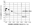
- FIG. 3 shows the relationship between the width ratio Wx/Wy of the active material layers X and Y and the capacity retention rate (cycle retention rate) at the 300th cycle from the measurement results using the non-aqueous electrolyte secondary batteries of Examples and Comparative Examples. It is a diagram.
- FIG. 10 is a schematic perspective view showing an electrode assembly including a negative electrode, which is another example of the embodiment;
- a negative electrode active material is arranged on a negative electrode current collector, and the packing density and energy density are increased by compressing with a roller or the like. This compression crushes the graphite particles and reduces the voids between the active materials, thereby increasing the packing density and energy density.
- the active material expands during charging, and the non-aqueous electrolyte existing between the active materials is driven out of the active material layer. During discharge, the active material of the negative electrode contracts, and the non-aqueous electrolyte penetrates into the active material layer and returns. less permeable.
- the negative electrode current collector constituting the negative electrode and the graphite particles disposed thereon are bound by a binder or the like. , the binding between the negative electrode current collector and the graphite particles tends to decrease. Therefore, depending on the state of charge, the graphite particles are likely to peel off from the negative electrode current collector, so it may not be possible to effectively suppress the deterioration of the charge-discharge cycle characteristics only by using graphite particles with a low internal porosity. .
- a layer containing many graphite particles with a small internal porosity and a layer containing many graphite particles with a large internal porosity are alternately arranged at a ratio within an appropriate range.
- the non-aqueous electrolyte can penetrate into the layer containing many graphite particles with large internal porosity via the layer containing many graphite particles with small internal porosity.
- the charge-discharge cycle characteristics can be improved without lowering the packing density of the active material in the negative electrode active material layer, and it is possible to achieve both high capacity and excellent charge-discharge cycle characteristics. have come up with a negative electrode for a non-aqueous electrolyte secondary battery.
- a negative electrode for a nonaqueous electrolyte secondary battery that is one aspect of the present disclosure is a negative electrode for a nonaqueous electrolyte secondary battery that includes a negative electrode current collector and a negative electrode active material layer provided on the negative electrode current collector.
- the negative electrode active material layer includes graphite particles A and graphite particles B as negative electrode active materials, and the content of the graphite particles A with respect to the total mass of the graphite particles A and the graphite particles B is different from each other, the first active material
- the layer X and the second active material layer Y are alternately arranged on the negative electrode current collector, the internal porosity of the graphite particles A is smaller than the internal porosity of the graphite particles B, and the graphite in the first active material layer X
- the content of the particles A is greater than the content of the graphite particles A in the second active material layer Y, and the ratio Wx between the width Wx of the first active material layer X and the width Wy of the second active material layer Y /Wy is 0.03 or more and 3.13 or less.
- non-aqueous electrolyte secondary battery of the present disclosure is not limited to the embodiments described below.
- drawings referred to in the description of the embodiments are described schematically.
- the configuration of the present disclosure is not limited to the laminate battery, and various battery forms such as flat prismatic batteries, cylindrical batteries, etc. can be applied to
- the electrode assembly is of a laminated type
- the configuration of the present disclosure can also be applied to a battery configuration having a wound electrode assembly.
- FIG. 1 is a cross-sectional view of a non-aqueous electrolyte secondary battery 10 that is an example of an embodiment.
- FIG. 2 is a schematic perspective view showing the electrode assembly 14.
- FIG. A nonaqueous electrolyte secondary battery 10 shown in FIG. 1 includes a battery case 11 composed of two laminate films 11a and 11b.
- a power-generating element (electrode body 14 and an electrolyte), which will be described later, is housed in the internal space of the housing portion 12 formed between the laminate films 11a and 11b.
- the outer peripheral portions of the laminate films 11a and 11b are joined together to form a sealing portion 13, which seals the internal space in which the power generation element is accommodated.
- the battery case 11 is a pouch type and is composed of two laminate films 11a and 11b.
- Each of the laminated films 11a and 11b is formed by laminating a resin layer on the surface of, for example, an aluminum foil.
- the resin material forming the resin layer include polyethylene, polypropylene, polyethylene terephthalate, and nylon. These resin layers may consist of only one layer, or may be a laminate of two or more layers.
- the non-aqueous electrolyte secondary battery 10 includes an electrode body 14 and an electrolyte (not shown) as power generating elements.
- the power generation element is housed in the housing portion 12 sealed with the sealing portion 13 as described above.
- the electrolyte for example, a non-aqueous electrolyte containing a non-aqueous solvent and an electrolyte salt such as a lithium salt dissolved in the non-aqueous solvent is used.
- the electrode body 14 has a laminated structure in which positive electrodes 20 and negative electrodes 30 are alternately laminated with separators (not shown) interposed therebetween.
- a current collecting portion consisting of an uncoated portion of each positive electrode 20 is one end in the width direction (upper end in FIG. 2) of a rectangular positive electrode main body (not shown) forming the positive electrode current collector (upper end in FIG. 2). 2) project in the same direction.
- a portion protruding from one end in the longitudinal direction of each positive electrode main body is laminated to form a positive current collecting tab 21 integrated with the electrode assembly 14 .
- the positive electrode lead 15 (FIG. 1) is superposed on one surface of the positive electrode current collecting tab 21 and is electrically connected by welding or the like.
- the current collector portion composed of the uncoated portion of each negative electrode 30 is the widthwise other end (the upper end in FIG. 2) of one longitudinal end (upper end of FIG. right end) in the same direction.
- a portion protruding from one longitudinal end of each negative electrode body portion 35 is laminated to form a negative electrode current collecting tab 31 integrated with the electrode body 14 .
- the negative electrode lead 16 (FIG. 1) is overlaid on one surface of the negative electrode current collecting tab 31 and electrically connected by welding or the like.
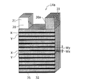
- FIG. 3 is a cross-sectional view of a negative electrode 30 that is an example of an embodiment.
- the negative electrode 30 is a secondary battery negative electrode having a negative electrode current collector 32 and a negative electrode active material layer 34 provided on the negative electrode current collector 32 .
- the negative electrode current collector 32 for example, a foil of a metal such as copper that is stable in the potential range of the negative electrode, a film having the metal on the surface layer, or the like is used.
- the negative electrode active material layer 34 contains graphite particles as a negative electrode active material. Moreover, the negative electrode active material layer 34 preferably contains a binder and the like.
- a negative electrode mixture slurry containing a negative electrode active material, a binder, etc. is prepared, and this negative electrode mixture slurry is applied onto the negative electrode current collector 32 and dried to form the negative electrode active material layer 34. , can be produced by rolling the negative electrode active material layer 34 . The details of the method for forming the negative electrode active material layer 34 will be described later.
- FIG. 4 is a cross-sectional view of graphite particles 40 in the negative electrode active material layer.
- the graphite particle 40 has closed voids 44 (hereinafter referred to as internal voids 44) that are not connected from the inside of the particle to the particle surface, and voids that are connected from the inside of the particle to the particle surface. and a gap 46 (hereinafter referred to as an external gap 46).
- the graphite particles 40 in this embodiment include graphite particles A and graphite particles B, and the internal porosity of the graphite particles A is smaller than the internal porosity of the graphite particles B.
- the graphite particles 40 include graphite particles A having an internal porosity of 5% or less and graphite particles B having an internal porosity of 8% to 20%.
- the internal porosity of the graphite particles A may be 5% or less in terms of suppressing deterioration of charge-discharge cycle characteristics, etc., but is preferably 1% to 5%, more preferably 3% to 5%. is.
- the internal porosity of the graphite particles B may be 8% to 20%, preferably 10% to 18%, and more preferably 12% to 12%, in order to suppress deterioration in charge-discharge cycle characteristics. 16%.
- the internal porosity of the graphite particles is a two-dimensional value obtained from the ratio of the area of the internal voids 44 of the graphite particles to the cross-sectional area of the graphite particles. Then, the internal porosity of the graphite particles is determined by the following procedure.
- ⁇ Method for measuring internal porosity> Exposing a section of the negative electrode active material layer. Examples of the method of exposing the cross section include a method of cutting a part of the negative electrode and processing it with an ion milling device (eg, IM4000PLUS manufactured by Hitachi High-Tech) to expose the cross section of the negative electrode active material layer. (2) Using a scanning electron microscope, take a backscattered electron image of the cross section of the exposed negative electrode active material layer. The magnification for capturing the reflected electron image is 3,000 times to 5,000 times.
- an ion milling device eg, IM4000PLUS manufactured by Hitachi High-Tech
- the area of the graphite particle cross section refers to the area of the region surrounded by the outer periphery of the graphite particle, that is, the area of the entire cross section of the graphite particle.
- voids with a width of 3 ⁇ m or less may be difficult to distinguish between internal voids and external voids in image analysis. may be Then, from the calculated area of the graphite particle cross section and the area of the internal voids in the graphite particle cross section, the internal porosity of the graphite particle (area of internal voids in the cross section of the graphite particle ⁇ 100/area of the cross section of the graphite particle) is calculated.
- the internal porosity of graphite particles A and B is an average value of 10 graphite particles A and B, respectively.
- Graphite particles A and B are produced, for example, as follows.
- ⁇ Graphite particles A having an internal porosity of 5% or less> For example, coke (precursor), which is the main raw material, is pulverized to a predetermined size, aggregated with a binder, fired at a temperature of 2600 ° C. or higher, graphitized, and sieved.
- Graphite particles A of a desired size are obtained.
- the internal porosity can be adjusted to 5% or less depending on the particle size of the precursor after pulverization, the particle size of the aggregated precursor, and the like.
- the average particle diameter (volume-based median diameter D50) of the pulverized precursor is preferably in the range of 12 ⁇ m to 20 ⁇ m.
- the internal porosity is reduced to 5% or less, it is preferable to increase the particle size of the precursor after pulverization.
- ⁇ Graphite particles B having an internal porosity of 8% to 20%> For example, coke (precursor), which is the main raw material, is pulverized to a predetermined size, aggregated with a binder, and further pressure-molded into a block shape, fired at a temperature of 2600 ° C. or higher, and graphitized.
- Graphite particles B of a desired size are obtained by pulverizing and sieving the block-shaped compact after graphitization.
- the internal porosity can be adjusted to 8% to 20% by adjusting the amount of volatile components added to the block-shaped compact. If part of the binder added to the coke (precursor) volatilizes during firing, the binder can be used as a volatile component. Pitch is exemplified as such a binder.
- Graphite particles A and B used in the present embodiment are not particularly limited and may be natural graphite, artificial graphite, or the like, but artificial graphite is preferable in terms of ease of adjustment of internal porosity.
- the interplanar spacing (d 002 ) of the (002) plane of the graphite particles A and B used in the present embodiment as determined by the X-ray wide-angle diffraction method is, for example, preferably 0.3354 nm or more, and preferably 0.3357 nm or more. is more preferably less than 0.340 nm, and more preferably 0.338 nm or less.
- the crystallite size (Lc(002)) of the graphite particles A and B used in the present embodiment determined by the X-ray diffraction method is, for example, preferably 5 nm or more, more preferably 10 nm or more. Also, it is preferably 300 nm or less, more preferably 200 nm or less.
- the battery capacity of the non-aqueous electrolyte secondary battery tends to be larger than when the above ranges are not satisfied.
- At least part of the surface of the graphite particles A is preferably coated with amorphous carbon. This improves the low-temperature characteristics of the non-aqueous electrolyte secondary battery.
- the content of the graphite particles A in the first active material layer X is greater than the content of the graphite particles A in the second active material layer Y.
- the ratio Wx/Wy of the width Wx of the first active material layer X to the width Wy of the second active material layer Y is 0.03 or more and 3.13 or less.
- the charge-discharge cycle characteristics of the non-aqueous electrolyte secondary battery 10 can be improved without lowering the filling density of the negative electrode active material in the negative electrode active material layer 34. It can be improved. Therefore, it is possible to achieve both high capacity of the non-aqueous electrolyte secondary battery 10 and excellent charge-discharge cycle characteristics.
- the first active material layer X only needs to contain more graphite particles A than the second active material layer Y, and the first active material layer X contains only graphite particles A.
- each of the first active material layer X and the second active material layer Y, or only the first active material layer X may contain both the graphite particles A and the graphite particles B.
- the first active material layer X preferably contains both the graphite particles A and the graphite particles B from the standpoint of ensuring adhesion between the negative electrode current collector 32 and the graphite particles.
- the mass ratio range of graphite particles A and graphite particles B in the first active material layer X is preferably 10:0 to 2:8 from the viewpoint of charge/discharge cycle characteristics and high capacity. , 6:4 to 3:7.
- a specific method for increasing the content of graphite particles A in the first active material layer X from that in the second active material layer Y will be described.
- a negative electrode active material containing graphite particles A (graphite particles A and B as necessary), a binder, and a solvent such as water are mixed to obtain a negative electrode mixture for the first active material layer X.
- a negative electrode mixture slurry for the second active material layer Y is prepared by mixing an adhesive and a solvent such as water. Then, on both surfaces of the negative electrode current collector, the negative electrode mixture slurry for the first active material layer X and the negative electrode mixture slurry for the second active material layer Y are alternately applied along the surface direction and dried.
- the negative electrode active material layer 34 can be formed.
- the negative electrode active material may contain other materials capable of reversibly intercalating and deintercalating lithium ions.
- it may contain a Si-based material.
- Si-based materials include, for example, Si, alloys containing Si, and silicon oxides such as SiO X (where X is 0.8 to 1.6).
- a Si-based material is a negative electrode material that can improve the battery capacity more than graphite particles, but on the other hand, it is disadvantageous in terms of charge-discharge cycle characteristics because of its large volume expansion due to charge-discharge.
- the negative electrode active material layer having the negative electrode active material containing the graphite particles A and B and the Si-based material it is not necessary to excessively increase the particle size of the graphite particles.
- the expansion and contraction of the Si-based material makes it easier to secure contact points, that is, electrical conductivity. This makes it possible to effectively suppress deterioration in charge-discharge cycle characteristics.
- the content of the Si-based material is, for example, preferably 1% by mass to 10% by mass with respect to the mass of the negative electrode active material in terms of improving battery capacity, suppressing deterioration in charge-discharge cycle characteristics, etc., and 3% by mass. % to 7 mass %.
- the negative electrode active material may contain the above other materials, and the content of the above other materials is preferably, for example, 10% by mass or less with respect to the mass of the negative electrode active material.
- binders include fluorine-based resins, PAN, polyimide-based resins, acrylic-based resins, polyolefin-based resins, styrene-butadiene rubber (SBR), nitrile-butadiene rubber (NBR), carboxymethylcellulose (CMC), or salts thereof. , polyacrylic acid (PAA) or salts thereof (PAA-Na, PAA-K, etc., and partially neutralized salts may also be used), polyvinyl alcohol (PVA), and the like. These may be used alone or in combination of two or more.
- the positive electrode 20 is composed of, for example, a positive electrode current collector such as a metal foil, and a positive electrode active material layer formed on the positive electrode current collector.
- a positive electrode current collector such as a metal foil
- a positive electrode active material layer formed on the positive electrode current collector.
- the positive electrode active material layer contains, for example, a positive electrode active material, a binder, a conductive agent, and the like.
- a positive electrode mixture slurry containing a positive electrode active material, a binder, a conductive agent, etc. is applied onto a positive electrode current collector and dried to form a positive electrode active material layer.
- a positive electrode current collector for example, a positive electrode current collector is applied onto a positive electrode current collector and dried to form a positive electrode active material layer.
- a positive electrode active material layer can be produced by rolling.
- Examples of positive electrode active materials include lithium transition metal oxides containing transition metal elements such as Co, Mn, and Ni.
- Lithium transition metal oxides include, for example , LixCoO2 , LixNiO2 , LixMnO2 , LixCoyNi1 - yO2 , LixCoyM1 - yOz , LixNi1- yMyOz , LixMn2O4 , LixMn2 - yMyO4 , LiMPO4 , Li2MPO4F ( M ; Na , Mg , Sc , Y , Mn, Fe, Co, Ni , Cu, Zn, Al, Cr, Pb, Sb, and B, 0 ⁇ x ⁇ 1.2, 0 ⁇ y ⁇ 0.9, 2.0 ⁇ z ⁇ 2.3).
- the positive electrode active material is Li x NiO 2 , Li x Co y Ni 1-y O 2 , Li x Ni 1- y My O z ( M; at least one of Na, Mg, Sc, Y, Mn, Fe, Co, Ni, Cu, Zn, Al, Cr, Pb, Sb, and B, 0 ⁇ x ⁇ 1.2, 0 ⁇ y ⁇ 0 .9, 2.0 ⁇ z ⁇ 2.3).
- Examples of conductive agents include carbon-based particles such as carbon black (CB), acetylene black (AB), ketjen black, and graphite. These may be used alone or in combination of two or more.
- CB carbon black
- AB acetylene black
- ketjen black ketjen black
- graphite graphite
- binders include fluorine-based resins such as polytetrafluoroethylene (PTFE) and polyvinylidene fluoride (PVdF), polyacrylonitrile (PAN), polyimide-based resins, acrylic-based resins, and polyolefin-based resins. These may be used alone or in combination of two or more.
- fluorine-based resins such as polytetrafluoroethylene (PTFE) and polyvinylidene fluoride (PVdF), polyacrylonitrile (PAN), polyimide-based resins, acrylic-based resins, and polyolefin-based resins. These may be used alone or in combination of two or more.
- a porous sheet or the like having ion permeability and insulation is used.
- porous sheets include microporous thin films, woven fabrics, and non-woven fabrics.
- Suitable materials for the separator include olefin resins such as polyethylene and polypropylene, and cellulose.
- the separator may be a laminate having a cellulose fiber layer and a thermoplastic resin fiber layer such as an olefin resin.
- a multilayer separator including a polyethylene layer and a polypropylene layer may be used, and a separator whose surface is coated with a material such as aramid resin or ceramic may be used.
- Non-aqueous electrolyte contains a non-aqueous solvent and an electrolyte salt dissolved in the non-aqueous solvent.
- non-aqueous solvents examples include esters, ethers, nitriles such as acetonitrile, amides such as dimethylformamide, and mixed solvents of two or more thereof.
- the non-aqueous solvent may contain a halogen-substituted product obtained by substituting at least part of the hydrogen atoms of these solvents with halogen atoms such as fluorine.
- esters examples include cyclic carbonates such as ethylene carbonate (EC), propylene carbonate (PC) and butylene carbonate, dimethyl carbonate (DMC), ethyl methyl carbonate (EMC), diethyl carbonate (DEC), methyl propyl carbonate. , Ethyl propyl carbonate, methyl isopropyl carbonate and other chain carbonates, ⁇ -butyrolactone, ⁇ -valerolactone and other cyclic carboxylic acid esters, methyl acetate, ethyl acetate, propyl acetate, methyl propionate (MP), ethyl propionate, etc. and chain carboxylic acid esters of.
- cyclic carbonates such as ethylene carbonate (EC), propylene carbonate (PC) and butylene carbonate, dimethyl carbonate (DMC), ethyl methyl carbonate (EMC), diethyl carbonate (DEC), methyl propyl carbonate.
- ethers examples include 1,3-dioxolane, 4-methyl-1,3-dioxolane, tetrahydrofuran, 2-methyltetrahydrofuran, propylene oxide, 1,2-butylene oxide, 1,3-dioxane, 1,4 -dioxane, 1,3,5-trioxane, furan, 2-methylfuran, 1,8-cineol, cyclic ethers such as crown ether, 1,2-dimethoxyethane, diethyl ether, dipropyl ether, diisopropyl ether, dibutyl ether , dihexyl ether, ethyl vinyl ether, butyl vinyl ether, methyl phenyl ether, ethyl phenyl ether, butyl phenyl ether, pentyl phenyl ether, methoxytoluene, benzyl ethyl ether, diphenyl ether, cycl
- a fluorinated cyclic carbonate such as fluoroethylene carbonate (FEC), a fluorinated chain carbonate, a fluorinated chain carboxylate such as methyl fluoropropionate (FMP), and the like.
- FEC fluoroethylene carbonate
- FMP fluorinated chain carboxylate
- FEC fluoroethylene carbonate
- FMP fluorinated chain carboxylate
- the electrolyte salt is a lithium salt.
- lithium salts include LiBF4 , LiClO4, LiPF6 , LiAsF6 , LiSbF6 , LiAlCl4 , LiSCN , LiCF3SO3 , LiCF3CO2 , Li ( P ( C2O4 ) F4 ), LiPF 6-x (C n F 2n+1 ) x (1 ⁇ x ⁇ 6, n is 1 or 2), LiB 10 Cl 10 , LiCl, LiBr, LiI, lithium chloroborane, lithium lower aliphatic carboxylate, Li 2B4O7 , borates such as Li( B ( C2O4 ) F2), LiN( SO2CF3 ) 2 , LiN( C1F2l + 1SO2 ) ( CmF2m + 1 SO 2 ) ⁇ l and m are integers of 1 or more ⁇ and the like.
- Lithium salts may be used singly or in combination. Of these, Li
- Example 1 [Preparation of positive electrode]
- Aluminum-containing lithium nickel cobaltate (LiNi 0.88 Co 0.09 Al 0.03 O 2 ) was used as the positive electrode active material. 100 parts by mass of the positive electrode active material, 0.8 parts by mass of carbon black as a conductive agent, and 0.7 parts by mass of polyvinylidene fluoride powder as a binder are mixed, and further N-methyl-2- An appropriate amount of pyrrolidone (NMP) was added to prepare a positive electrode mixture slurry. This slurry was applied to both sides of a positive electrode current collector made of aluminum foil (thickness: 15 ⁇ m) by a doctor blade method, and the coating film was dried.
- NMP pyrrolidone
- the total coating amount of the mixture on both sides was 560 g/m 2 .
- the coating film was rolled with a rolling roller, and then cut into a predetermined electrode size to prepare a positive electrode in which positive electrode active material layers were formed on both sides of a positive electrode current collector.
- the thickness of the electrode plate was adjusted to 161 ⁇ m.
- Coke was pulverized to an average particle size (median diameter D50) of 12 ⁇ m.
- Pitch as a binder was added to the pulverized coke, and the coke was agglomerated until the average particle size (median diameter D50) reached 17 ⁇ m.
- the aggregate was calcined at a temperature of 2800° C. to graphitize it, it was sieved using a 250-mesh sieve to obtain graphite particles A having an average particle diameter (median diameter D50) of 23 ⁇ m.
- [Preparation of negative electrode] 47.5 parts by mass of graphite particles A, 47.5 parts by mass of graphite particles B, and 5 parts by mass of SiO were mixed, and this was used as the negative electrode active material G1 for the first active material layer X.
- CMC carboxymethyl cellulose
- SBR styrene-butadiene copolymer rubber
- Negative electrode active material G2 1 part by mass of carboxymethyl cellulose (CMC), and water were mixed. This mixture was mixed with 1 part by mass of styrene-butadiene copolymer rubber (SBR) and water to prepare a negative electrode mixture slurry for the second active material layer Y.
- CMC carboxymethyl cellulose
- SBR styrene-butadiene copolymer rubber
- the negative electrode mixture slurry for the first active material layer X and the negative electrode mixture slurry for the second active material layer Y were coated on both sides of the negative electrode current collector made of copper foil with a width of 0.1 mm and a width of 3.2 mm, respectively. were applied at the same time using a die coater, and the coating film was dried. At this time, the total coating amount of the mixture on both sides was 282 g/m 2 . Then, after rolling the coating film with a rolling roller, it was cut into a predetermined electrode size to prepare a negative electrode having negative electrode active material layers formed on both sides of the negative electrode current collector. In the rolling, the thickness of the electrode plate was adjusted to 161 ⁇ m.
- Non-aqueous electrolyte 2 parts by mass of vinylene carbonate (VC) was added to a non-aqueous solvent obtained by mixing ethylene carbonate (EC), dimethyl carbonate (DMC), and ethyl methyl carbonate (EMC) in a volume ratio of 2:6:2. LiPF 6 as an electrolyte was dissolved at a concentration of 1.3 mol/L. A non-aqueous electrolyte was thus prepared.
- EC ethylene carbonate
- DMC dimethyl carbonate
- EMC ethyl methyl carbonate
- Non-aqueous electrolyte secondary battery Five sheets of positive electrode and six sheets of negative electrode are laminated so that two negative electrodes are positioned outside, and a separator having a thickness of 20 ⁇ m made of polyethylene microporous film is interposed between the positive electrode and the negative electrode. An electrode body was produced. Then, after attaching the positive electrode lead to the positive electrode current collecting tab and attaching the negative electrode lead to the negative electrode current collecting tab, the electrode body and 3.5 g of the non-aqueous electrolyte are housed in a battery case made of an aluminum laminate film, A non-aqueous electrolyte secondary battery of Example 1 was produced by sealing the opening of the battery case.
- Example 2 The application width of the negative electrode mixture slurry for the first active material layer X is set to 0.2 mm, and the application width of the negative electrode mixture slurry for the second active material layer Y is set to 3.1 mm. Both sides of the current collector were coated.
- a non-aqueous electrolyte secondary battery of Example 2 was produced in the same manner as in Example 1 except for the above.
- Example 3 The application width of the negative electrode mixture slurry for the first active material layer X is set to 1.0 mm, and the application width of the negative electrode mixture slurry for the second active material layer Y is set to 2.3 mm. Both sides of the current collector were coated.
- a non-aqueous electrolyte secondary battery of Example 3 was produced in the same manner as in Example 1 except for the above.
- Example 4 The application width of the negative electrode mixture slurry for the first active material layer X is set to 2.0 mm, and the application width of the negative electrode mixture slurry for the second active material layer Y is set to 1.3 mm. Both sides of the current collector were coated.
- a non-aqueous electrolyte secondary battery of Example 4 was produced in the same manner as in Example 1 except for the above.
- Example 5 The application width of the negative electrode mixture slurry for the first active material layer X is set to 2.5 mm, and the application width of the negative electrode mixture slurry for the second active material layer Y is set to 0.8 mm. Both sides of the current collector were coated.
- a non-aqueous electrolyte secondary battery of Example 5 was produced in the same manner as in Example 1 except for the above.
- Table 1 summarizes the results of the capacity retention rate in charge-discharge cycles of the non-aqueous electrolyte secondary batteries of each example and each comparative example. It should be noted that the higher the value of the capacity retention rate in charge-discharge cycles, the better the charge-discharge cycle characteristics.
- FIG. 5 shows the width ratio Wx/Wy of the first active material layer X and the second active material layer Y and the capacity retention at the 300th cycle from the measurement results using the non-aqueous electrolyte secondary batteries of Examples and Comparative Examples. rate (cycle maintenance rate).
- black circles indicate Examples 1-5, and white rhombuses indicate Comparative Examples 1-2.
- the first active material layer X contains both graphite particles A and graphite particles B.
- the presence of the graphite particles B that are moderately crushed during electrode formation makes it possible to achieve better adhesion between the negative electrode current collector and the graphite particles than in the case where the first active material layer X is formed only of the graphite particles A that are less likely to be crushed. can ensure the integrity.
- the graphite particles are less likely to peel off from the negative electrode current collector during charge-discharge cycles, making it easier to ensure excellent charge-discharge cycle characteristics.
- FIG. 6 is a schematic perspective view showing an electrode body 14a including a negative electrode 30a, which is another example of the embodiment.
- the first active material layer X and the second active material layer Y form the negative electrode current collector 32 on the negative electrode current collector 32.
- Each of the first active material layers X and each of the second active material layers Y extends in the width direction of the negative electrode main body 35 (horizontal direction in FIG. 6) and reaches both ends of the negative electrode main body 35 in the width direction.
- the content of the graphite particles A in the first active material layer X is greater than the content of the graphite particles A in the second active material layer Y. Further, the ratio Wx/Wy of the width Wx of the first active material layer X to the width Wy of the second active material layer Y is 0.03 or more and 3.13 or less. Also in the case of the configuration of this example, as with the configurations of FIGS. 1 to 4, both excellent charge-discharge cycle characteristics and high capacity of the non-aqueous electrolyte secondary battery can be achieved. Other configurations and actions in this example are the same as those in FIGS.
- the electrode body is a laminated type was described, but the electrode body is a winding in which the positive electrode and the negative electrode are wound with a separator interposed therebetween. It may be a circular type. Also in this case, the first active material layers X and the second active material layers Y are alternately arranged on the negative electrode current collector so that the ratio Wx/Wy is 0.03 or more and 3.13 or less. As a result, both excellent charge-discharge cycle characteristics and high capacity of the non-aqueous electrolyte secondary battery can be achieved.
- non-aqueous electrolyte secondary battery 11 battery case, 11a, 11b laminate film, 12 containing portion, 13 sealing portion, 14 electrode body, 15 positive electrode lead, 16 negative electrode lead, 20 positive electrode, 21 positive electrode current collecting tab, 30 negative electrode , 31 negative electrode current collector tab, 32 negative electrode current collector, 34 negative electrode active material layer, 35 negative electrode main body, 40 graphite particles, 44 internal voids, 46 external voids.
Landscapes
- Chemical & Material Sciences (AREA)
- Chemical Kinetics & Catalysis (AREA)
- Electrochemistry (AREA)
- General Chemical & Material Sciences (AREA)
- Composite Materials (AREA)
- Engineering & Computer Science (AREA)
- Inorganic Chemistry (AREA)
- Materials Engineering (AREA)
- Manufacturing & Machinery (AREA)
- Battery Electrode And Active Subsutance (AREA)
- Secondary Cells (AREA)
Abstract
Priority Applications (4)
| Application Number | Priority Date | Filing Date | Title |
|---|---|---|---|
| CN202280015082.XA CN116964773A (zh) | 2021-02-25 | 2022-02-18 | 非水电解质二次电池用负极和非水电解质二次电池 |
| EP22759525.3A EP4300622A1 (fr) | 2021-02-25 | 2022-02-18 | Électrode négative pour batteries secondaires à électrolyte non aqueux, et batterie secondaire à électrolyte non aqueux |
| JP2023502358A JPWO2022181489A1 (fr) | 2021-02-25 | 2022-02-18 | |
| US18/277,190 US20240097101A1 (en) | 2021-02-25 | 2022-02-18 | Negative electrode for nonaqueous electrolyte secondary batteries, and nonaqueous electrolyte secondary battery |
Applications Claiming Priority (2)
| Application Number | Priority Date | Filing Date | Title |
|---|---|---|---|
| JP2021-028420 | 2021-02-25 | ||
| JP2021028420 | 2021-02-25 |
Publications (1)
| Publication Number | Publication Date |
|---|---|
| WO2022181489A1 true WO2022181489A1 (fr) | 2022-09-01 |
Family
ID=83049351
Family Applications (1)
| Application Number | Title | Priority Date | Filing Date |
|---|---|---|---|
| PCT/JP2022/006688 WO2022181489A1 (fr) | 2021-02-25 | 2022-02-18 | Électrode négative pour batteries secondaires à électrolyte non aqueux, et batterie secondaire à électrolyte non aqueux |
Country Status (5)
| Country | Link |
|---|---|
| US (1) | US20240097101A1 (fr) |
| EP (1) | EP4300622A1 (fr) |
| JP (1) | JPWO2022181489A1 (fr) |
| CN (1) | CN116964773A (fr) |
| WO (1) | WO2022181489A1 (fr) |
Cited By (3)
| Publication number | Priority date | Publication date | Assignee | Title |
|---|---|---|---|---|
| CN115394952A (zh) * | 2022-09-02 | 2022-11-25 | 湖北亿纬动力有限公司 | 一种厚电极及其制作方法与应用 |
| CN115832202A (zh) * | 2022-12-21 | 2023-03-21 | 楚能新能源股份有限公司 | 一种负极极片、锂离子电池及其制备方法 |
| WO2024048732A1 (fr) * | 2022-08-31 | 2024-03-07 | パナソニックエナジー株式会社 | Électrode négative de batterie secondaire, batterie secondaire et procédé de fabrication d'électrode négative de batterie secondaire |
Citations (7)
| Publication number | Priority date | Publication date | Assignee | Title |
|---|---|---|---|---|
| JPH09298057A (ja) | 1996-04-30 | 1997-11-18 | Sanyo Electric Co Ltd | リチウムイオン電池 |
| JP2000090980A (ja) | 1998-09-10 | 2000-03-31 | Sanyo Electric Co Ltd | リチウム二次電池 |
| JP2013246900A (ja) | 2012-05-23 | 2013-12-09 | Toyota Motor Corp | 二次電池 |
| WO2019239948A1 (fr) * | 2018-06-15 | 2019-12-19 | パナソニックIpマネジメント株式会社 | Batterie secondaire à électrolyte non aqueux |
| WO2019239652A1 (fr) * | 2018-06-15 | 2019-12-19 | 三洋電機株式会社 | Accumulateur à électrolyte non aqueux |
| WO2020044930A1 (fr) * | 2018-08-29 | 2020-03-05 | パナソニックIpマネジメント株式会社 | Batterie secondaire à électrolyte non aqueux |
| WO2020175361A1 (fr) * | 2019-02-28 | 2020-09-03 | 三洋電機株式会社 | Batterie secondaire à électrolyte non aqueux |
-
2022
- 2022-02-18 US US18/277,190 patent/US20240097101A1/en active Pending
- 2022-02-18 WO PCT/JP2022/006688 patent/WO2022181489A1/fr active Application Filing
- 2022-02-18 CN CN202280015082.XA patent/CN116964773A/zh active Pending
- 2022-02-18 JP JP2023502358A patent/JPWO2022181489A1/ja active Pending
- 2022-02-18 EP EP22759525.3A patent/EP4300622A1/fr active Pending
Patent Citations (7)
| Publication number | Priority date | Publication date | Assignee | Title |
|---|---|---|---|---|
| JPH09298057A (ja) | 1996-04-30 | 1997-11-18 | Sanyo Electric Co Ltd | リチウムイオン電池 |
| JP2000090980A (ja) | 1998-09-10 | 2000-03-31 | Sanyo Electric Co Ltd | リチウム二次電池 |
| JP2013246900A (ja) | 2012-05-23 | 2013-12-09 | Toyota Motor Corp | 二次電池 |
| WO2019239948A1 (fr) * | 2018-06-15 | 2019-12-19 | パナソニックIpマネジメント株式会社 | Batterie secondaire à électrolyte non aqueux |
| WO2019239652A1 (fr) * | 2018-06-15 | 2019-12-19 | 三洋電機株式会社 | Accumulateur à électrolyte non aqueux |
| WO2020044930A1 (fr) * | 2018-08-29 | 2020-03-05 | パナソニックIpマネジメント株式会社 | Batterie secondaire à électrolyte non aqueux |
| WO2020175361A1 (fr) * | 2019-02-28 | 2020-09-03 | 三洋電機株式会社 | Batterie secondaire à électrolyte non aqueux |
Cited By (4)
| Publication number | Priority date | Publication date | Assignee | Title |
|---|---|---|---|---|
| WO2024048732A1 (fr) * | 2022-08-31 | 2024-03-07 | パナソニックエナジー株式会社 | Électrode négative de batterie secondaire, batterie secondaire et procédé de fabrication d'électrode négative de batterie secondaire |
| CN115394952A (zh) * | 2022-09-02 | 2022-11-25 | 湖北亿纬动力有限公司 | 一种厚电极及其制作方法与应用 |
| CN115832202A (zh) * | 2022-12-21 | 2023-03-21 | 楚能新能源股份有限公司 | 一种负极极片、锂离子电池及其制备方法 |
| CN115832202B (zh) * | 2022-12-21 | 2023-09-29 | 楚能新能源股份有限公司 | 一种负极极片、锂离子电池及其制备方法 |
Also Published As
| Publication number | Publication date |
|---|---|
| CN116964773A (zh) | 2023-10-27 |
| JPWO2022181489A1 (fr) | 2022-09-01 |
| US20240097101A1 (en) | 2024-03-21 |
| EP4300622A1 (fr) | 2024-01-03 |
Similar Documents
| Publication | Publication Date | Title |
|---|---|---|
| JP7319265B2 (ja) | 非水電解質二次電池 | |
| WO2022181489A1 (fr) | Électrode négative pour batteries secondaires à électrolyte non aqueux, et batterie secondaire à électrolyte non aqueux | |
| JP7182107B2 (ja) | 非水電解質二次電池用正極活物質、非水電解質二次電池用正極活物質の製造方法、及び非水電解質二次電池 | |
| JP7336736B2 (ja) | 非水電解質二次電池 | |
| JPWO2020175361A1 (ja) | 非水電解質二次電池 | |
| JP7203358B2 (ja) | リチウムイオン電池用負極活物質及びリチウムイオン電池 | |
| WO2021117480A1 (fr) | Batterie secondaire à électrolyte non aqueux | |
| JP2023001306A (ja) | リチウム二次電池用電極 | |
| WO2021106730A1 (fr) | Batterie secondaire à électrolyte non aqueux | |
| WO2021111931A1 (fr) | Batterie secondaire à électrolyte non aqueux | |
| JP7233013B2 (ja) | 非水電解質二次電池 | |
| WO2023053625A1 (fr) | Batterie rechargeable à électrolyte non aqueux | |
| US20230187629A1 (en) | Positive electrode active material for non-aqueous electrolyte secondary battery, and non-aqueous electrolyte secondary battery | |
| JP7236657B2 (ja) | 非水電解質二次電池 | |
| WO2019207933A1 (fr) | Batterie secondaire à électrolyte non aqueux | |
| WO2023157746A1 (fr) | Batterie secondaire à électrolyte non aqueux | |
| WO2022158375A1 (fr) | Batterie secondaire à électrolyte non aqueux | |
| WO2023276582A1 (fr) | Batterie secondaire à électrolyte non aqueux | |
| WO2024004837A1 (fr) | Électrode négative pour batteries secondaires à électrolyte non aqueux, et batterie secondaire à électrolyte non aqueux | |
| WO2023149529A1 (fr) | Batterie secondaire à électrolyte non aqueux | |
| WO2024004836A1 (fr) | Batterie secondaire à électrolyte non aqueux | |
| WO2021106727A1 (fr) | Électrode négative pour batteries secondaires à électrolyte non aqueux, batterie secondaire à électrolyte non aqueux, et procédé de production d'électrode négative pour batteries secondaires à électrolyte non aqueux | |
| WO2024024505A1 (fr) | Électrode négative pour batteries secondaires à électrolyte non aqueux, et batterie secondaire à électrolyte non aqueux | |
| WO2022230654A1 (fr) | Batterie secondaire à électrolyte non aqueux | |
| WO2023176503A1 (fr) | Batterie secondaire à électrolyte non aqueux |
Legal Events
| Date | Code | Title | Description |
|---|---|---|---|
| 121 | Ep: the epo has been informed by wipo that ep was designated in this application |
Ref document number: 22759525 Country of ref document: EP Kind code of ref document: A1 |
|
| WWE | Wipo information: entry into national phase |
Ref document number: 2023502358 Country of ref document: JP |
|
| WWE | Wipo information: entry into national phase |
Ref document number: 18277190 Country of ref document: US |
|
| WWE | Wipo information: entry into national phase |
Ref document number: 202280015082.X Country of ref document: CN |
|
| WWE | Wipo information: entry into national phase |
Ref document number: 2022759525 Country of ref document: EP |
|
| NENP | Non-entry into the national phase |
Ref country code: DE |
|
| ENP | Entry into the national phase |
Ref document number: 2022759525 Country of ref document: EP Effective date: 20230925 |