WO2022158375A1 - Batterie secondaire à électrolyte non aqueux - Google Patents
Batterie secondaire à électrolyte non aqueux Download PDFInfo
- Publication number
- WO2022158375A1 WO2022158375A1 PCT/JP2022/001019 JP2022001019W WO2022158375A1 WO 2022158375 A1 WO2022158375 A1 WO 2022158375A1 JP 2022001019 W JP2022001019 W JP 2022001019W WO 2022158375 A1 WO2022158375 A1 WO 2022158375A1
- Authority
- WO
- WIPO (PCT)
- Prior art keywords
- negative electrode
- mixture layer
- electrode mixture
- graphite particles
- aqueous electrolyte
- Prior art date
Links
- 239000011255 nonaqueous electrolyte Substances 0.000 title claims abstract description 41
- 239000000203 mixture Substances 0.000 claims abstract description 138
- 239000002245 particle Substances 0.000 claims abstract description 85
- OKTJSMMVPCPJKN-UHFFFAOYSA-N Carbon Chemical compound [C] OKTJSMMVPCPJKN-UHFFFAOYSA-N 0.000 claims abstract description 76
- 229910002804 graphite Inorganic materials 0.000 claims abstract description 70
- 239000010439 graphite Substances 0.000 claims abstract description 70
- 239000003989 dielectric material Substances 0.000 claims abstract description 23
- 239000007773 negative electrode material Substances 0.000 claims description 24
- GWEVSGVZZGPLCZ-UHFFFAOYSA-N Titan oxide Chemical compound O=[Ti]=O GWEVSGVZZGPLCZ-UHFFFAOYSA-N 0.000 claims description 12
- 239000002210 silicon-based material Substances 0.000 claims description 6
- WHXSMMKQMYFTQS-UHFFFAOYSA-N Lithium Chemical compound [Li] WHXSMMKQMYFTQS-UHFFFAOYSA-N 0.000 claims description 5
- 229910052744 lithium Inorganic materials 0.000 claims description 5
- OGIDPMRJRNCKJF-UHFFFAOYSA-N titanium oxide Inorganic materials [Ti]=O OGIDPMRJRNCKJF-UHFFFAOYSA-N 0.000 claims description 5
- RTAQQCXQSZGOHL-UHFFFAOYSA-N Titanium Chemical compound [Ti] RTAQQCXQSZGOHL-UHFFFAOYSA-N 0.000 claims description 3
- 238000007600 charging Methods 0.000 abstract description 6
- 230000007423 decrease Effects 0.000 abstract description 6
- 238000007599 discharging Methods 0.000 abstract description 6
- 239000010410 layer Substances 0.000 description 94
- 239000002002 slurry Substances 0.000 description 25
- 239000011230 binding agent Substances 0.000 description 15
- -1 polytetrafluoroethylene Polymers 0.000 description 12
- 238000007789 sealing Methods 0.000 description 12
- 230000000052 comparative effect Effects 0.000 description 10
- 239000000571 coke Substances 0.000 description 8
- 229910052751 metal Inorganic materials 0.000 description 8
- 238000000034 method Methods 0.000 description 8
- 229910010413 TiO 2 Inorganic materials 0.000 description 7
- 239000000463 material Substances 0.000 description 7
- 239000002184 metal Substances 0.000 description 7
- 239000002243 precursor Substances 0.000 description 7
- 238000005096 rolling process Methods 0.000 description 7
- 239000010408 film Substances 0.000 description 6
- 230000014759 maintenance of location Effects 0.000 description 6
- 238000004519 manufacturing process Methods 0.000 description 6
- PXHVJJICTQNCMI-UHFFFAOYSA-N nickel Substances [Ni] PXHVJJICTQNCMI-UHFFFAOYSA-N 0.000 description 6
- 238000012856 packing Methods 0.000 description 6
- 239000007774 positive electrode material Substances 0.000 description 6
- 229910052782 aluminium Inorganic materials 0.000 description 5
- 239000003125 aqueous solvent Substances 0.000 description 5
- 230000035699 permeability Effects 0.000 description 5
- 229920005989 resin Polymers 0.000 description 5
- 239000011347 resin Substances 0.000 description 5
- 150000003839 salts Chemical class 0.000 description 5
- 229920003048 styrene butadiene rubber Polymers 0.000 description 5
- 239000011800 void material Substances 0.000 description 5
- KMTRUDSVKNLOMY-UHFFFAOYSA-N Ethylene carbonate Chemical compound O=C1OCCO1 KMTRUDSVKNLOMY-UHFFFAOYSA-N 0.000 description 4
- SECXISVLQFMRJM-UHFFFAOYSA-N N-Methylpyrrolidone Chemical compound CN1CCCC1=O SECXISVLQFMRJM-UHFFFAOYSA-N 0.000 description 4
- 239000011248 coating agent Substances 0.000 description 4
- 238000000576 coating method Methods 0.000 description 4
- 239000006258 conductive agent Substances 0.000 description 4
- 239000011888 foil Substances 0.000 description 4
- 229910003002 lithium salt Inorganic materials 0.000 description 4
- 159000000002 lithium salts Chemical group 0.000 description 4
- 229920005672 polyolefin resin Polymers 0.000 description 4
- 238000002360 preparation method Methods 0.000 description 4
- LIVNPJMFVYWSIS-UHFFFAOYSA-N silicon monoxide Chemical class [Si-]#[O+] LIVNPJMFVYWSIS-UHFFFAOYSA-N 0.000 description 4
- 239000002904 solvent Substances 0.000 description 4
- XLYOFNOQVPJJNP-UHFFFAOYSA-N water Substances O XLYOFNOQVPJJNP-UHFFFAOYSA-N 0.000 description 4
- UZKWTJUDCOPSNM-UHFFFAOYSA-N 1-ethenoxybutane Chemical compound CCCCOC=C UZKWTJUDCOPSNM-UHFFFAOYSA-N 0.000 description 3
- WEVYAHXRMPXWCK-UHFFFAOYSA-N Acetonitrile Chemical compound CC#N WEVYAHXRMPXWCK-UHFFFAOYSA-N 0.000 description 3
- 229920002134 Carboxymethyl cellulose Polymers 0.000 description 3
- RTZKZFJDLAIYFH-UHFFFAOYSA-N Diethyl ether Chemical compound CCOCC RTZKZFJDLAIYFH-UHFFFAOYSA-N 0.000 description 3
- XEKOWRVHYACXOJ-UHFFFAOYSA-N Ethyl acetate Chemical compound CCOC(C)=O XEKOWRVHYACXOJ-UHFFFAOYSA-N 0.000 description 3
- YCKRFDGAMUMZLT-UHFFFAOYSA-N Fluorine atom Chemical compound [F] YCKRFDGAMUMZLT-UHFFFAOYSA-N 0.000 description 3
- ZMXDDKWLCZADIW-UHFFFAOYSA-N N,N-Dimethylformamide Chemical compound CN(C)C=O ZMXDDKWLCZADIW-UHFFFAOYSA-N 0.000 description 3
- 239000002033 PVDF binder Substances 0.000 description 3
- 239000004698 Polyethylene Substances 0.000 description 3
- 239000000956 alloy Substances 0.000 description 3
- 229910045601 alloy Inorganic materials 0.000 description 3
- XAGFODPZIPBFFR-UHFFFAOYSA-N aluminium Chemical compound [Al] XAGFODPZIPBFFR-UHFFFAOYSA-N 0.000 description 3
- 150000002170 ethers Chemical class 0.000 description 3
- 238000011156 evaluation Methods 0.000 description 3
- 229910052731 fluorine Inorganic materials 0.000 description 3
- 239000011737 fluorine Substances 0.000 description 3
- 229910052748 manganese Inorganic materials 0.000 description 3
- 229920002239 polyacrylonitrile Polymers 0.000 description 3
- 229920000573 polyethylene Polymers 0.000 description 3
- 229920002981 polyvinylidene fluoride Polymers 0.000 description 3
- 238000010298 pulverizing process Methods 0.000 description 3
- YLQBMQCUIZJEEH-UHFFFAOYSA-N tetrahydrofuran Natural products C=1C=COC=1 YLQBMQCUIZJEEH-UHFFFAOYSA-N 0.000 description 3
- DHKHKXVYLBGOIT-UHFFFAOYSA-N 1,1-Diethoxyethane Chemical compound CCOC(C)OCC DHKHKXVYLBGOIT-UHFFFAOYSA-N 0.000 description 2
- VAYTZRYEBVHVLE-UHFFFAOYSA-N 1,3-dioxol-2-one Chemical compound O=C1OC=CO1 VAYTZRYEBVHVLE-UHFFFAOYSA-N 0.000 description 2
- VQKFNUFAXTZWDK-UHFFFAOYSA-N 2-Methylfuran Chemical compound CC1=CC=CO1 VQKFNUFAXTZWDK-UHFFFAOYSA-N 0.000 description 2
- YEJRWHAVMIAJKC-UHFFFAOYSA-N 4-Butyrolactone Chemical compound O=C1CCCO1 YEJRWHAVMIAJKC-UHFFFAOYSA-N 0.000 description 2
- SBLRHMKNNHXPHG-UHFFFAOYSA-N 4-fluoro-1,3-dioxolan-2-one Chemical compound FC1COC(=O)O1 SBLRHMKNNHXPHG-UHFFFAOYSA-N 0.000 description 2
- RYGMFSIKBFXOCR-UHFFFAOYSA-N Copper Chemical compound [Cu] RYGMFSIKBFXOCR-UHFFFAOYSA-N 0.000 description 2
- OIFBSDVPJOWBCH-UHFFFAOYSA-N Diethyl carbonate Chemical compound CCOC(=O)OCC OIFBSDVPJOWBCH-UHFFFAOYSA-N 0.000 description 2
- XTHFKEDIFFGKHM-UHFFFAOYSA-N Dimethoxyethane Chemical compound COCCOC XTHFKEDIFFGKHM-UHFFFAOYSA-N 0.000 description 2
- HBBGRARXTFLTSG-UHFFFAOYSA-N Lithium ion Chemical compound [Li+] HBBGRARXTFLTSG-UHFFFAOYSA-N 0.000 description 2
- RJUFJBKOKNCXHH-UHFFFAOYSA-N Methyl propionate Chemical compound CCC(=O)OC RJUFJBKOKNCXHH-UHFFFAOYSA-N 0.000 description 2
- 229920000459 Nitrile rubber Polymers 0.000 description 2
- 239000004642 Polyimide Substances 0.000 description 2
- 239000004743 Polypropylene Substances 0.000 description 2
- 239000004372 Polyvinyl alcohol Substances 0.000 description 2
- 239000002174 Styrene-butadiene Substances 0.000 description 2
- WYURNTSHIVDZCO-UHFFFAOYSA-N Tetrahydrofuran Chemical compound C1CCOC1 WYURNTSHIVDZCO-UHFFFAOYSA-N 0.000 description 2
- 239000006230 acetylene black Substances 0.000 description 2
- RDOXTESZEPMUJZ-UHFFFAOYSA-N anisole Chemical compound COC1=CC=CC=C1 RDOXTESZEPMUJZ-UHFFFAOYSA-N 0.000 description 2
- 229910052787 antimony Inorganic materials 0.000 description 2
- 229910021383 artificial graphite Inorganic materials 0.000 description 2
- 229910052796 boron Inorganic materials 0.000 description 2
- QHIWVLPBUQWDMQ-UHFFFAOYSA-N butyl prop-2-enoate;methyl 2-methylprop-2-enoate;prop-2-enoic acid Chemical compound OC(=O)C=C.COC(=O)C(C)=C.CCCCOC(=O)C=C QHIWVLPBUQWDMQ-UHFFFAOYSA-N 0.000 description 2
- 239000006229 carbon black Substances 0.000 description 2
- 239000002041 carbon nanotube Substances 0.000 description 2
- 229910021393 carbon nanotube Inorganic materials 0.000 description 2
- 150000005678 chain carbonates Chemical class 0.000 description 2
- 229910052804 chromium Inorganic materials 0.000 description 2
- 229910052802 copper Inorganic materials 0.000 description 2
- 239000010949 copper Substances 0.000 description 2
- 150000005676 cyclic carbonates Chemical class 0.000 description 2
- 238000010586 diagram Methods 0.000 description 2
- MHDVGSVTJDSBDK-UHFFFAOYSA-N dibenzyl ether Chemical compound C=1C=CC=CC=1COCC1=CC=CC=C1 MHDVGSVTJDSBDK-UHFFFAOYSA-N 0.000 description 2
- IEJIGPNLZYLLBP-UHFFFAOYSA-N dimethyl carbonate Chemical compound COC(=O)OC IEJIGPNLZYLLBP-UHFFFAOYSA-N 0.000 description 2
- USIUVYZYUHIAEV-UHFFFAOYSA-N diphenyl ether Chemical compound C=1C=CC=CC=1OC1=CC=CC=C1 USIUVYZYUHIAEV-UHFFFAOYSA-N 0.000 description 2
- 238000007606 doctor blade method Methods 0.000 description 2
- 229920001971 elastomer Polymers 0.000 description 2
- 239000003792 electrolyte Substances 0.000 description 2
- 239000008151 electrolyte solution Substances 0.000 description 2
- 230000007613 environmental effect Effects 0.000 description 2
- 150000002148 esters Chemical class 0.000 description 2
- FJKIXWOMBXYWOQ-UHFFFAOYSA-N ethenoxyethane Chemical compound CCOC=C FJKIXWOMBXYWOQ-UHFFFAOYSA-N 0.000 description 2
- JBTWLSYIZRCDFO-UHFFFAOYSA-N ethyl methyl carbonate Chemical compound CCOC(=O)OC JBTWLSYIZRCDFO-UHFFFAOYSA-N 0.000 description 2
- FKRCODPIKNYEAC-UHFFFAOYSA-N ethyl propionate Chemical compound CCOC(=O)CC FKRCODPIKNYEAC-UHFFFAOYSA-N 0.000 description 2
- 238000010304 firing Methods 0.000 description 2
- GAEKPEKOJKCEMS-UHFFFAOYSA-N gamma-valerolactone Chemical compound CC1CCC(=O)O1 GAEKPEKOJKCEMS-UHFFFAOYSA-N 0.000 description 2
- 229910052742 iron Inorganic materials 0.000 description 2
- 229910052745 lead Inorganic materials 0.000 description 2
- AMXOYNBUYSYVKV-UHFFFAOYSA-M lithium bromide Chemical compound [Li+].[Br-] AMXOYNBUYSYVKV-UHFFFAOYSA-M 0.000 description 2
- KWGKDLIKAYFUFQ-UHFFFAOYSA-M lithium chloride Chemical compound [Li+].[Cl-] KWGKDLIKAYFUFQ-UHFFFAOYSA-M 0.000 description 2
- 229910001416 lithium ion Inorganic materials 0.000 description 2
- 229910021437 lithium-transition metal oxide Inorganic materials 0.000 description 2
- 229940017219 methyl propionate Drugs 0.000 description 2
- 229910052759 nickel Inorganic materials 0.000 description 2
- 229920001721 polyimide Polymers 0.000 description 2
- 229920001155 polypropylene Polymers 0.000 description 2
- 229920001343 polytetrafluoroethylene Polymers 0.000 description 2
- 239000004810 polytetrafluoroethylene Substances 0.000 description 2
- 229920002451 polyvinyl alcohol Polymers 0.000 description 2
- RUOJZAUFBMNUDX-UHFFFAOYSA-N propylene carbonate Chemical compound CC1COC(=O)O1 RUOJZAUFBMNUDX-UHFFFAOYSA-N 0.000 description 2
- 239000002994 raw material Substances 0.000 description 2
- 239000005060 rubber Substances 0.000 description 2
- 229910052814 silicon oxide Inorganic materials 0.000 description 2
- 239000002344 surface layer Substances 0.000 description 2
- ZUHZGEOKBKGPSW-UHFFFAOYSA-N tetraglyme Chemical compound COCCOCCOCCOCCOC ZUHZGEOKBKGPSW-UHFFFAOYSA-N 0.000 description 2
- ABDKAPXRBAPSQN-UHFFFAOYSA-N veratrole Chemical compound COC1=CC=CC=C1OC ABDKAPXRBAPSQN-UHFFFAOYSA-N 0.000 description 2
- 229910052725 zinc Inorganic materials 0.000 description 2
- 239000011701 zinc Substances 0.000 description 2
- RBACIKXCRWGCBB-UHFFFAOYSA-N 1,2-Epoxybutane Chemical compound CCC1CO1 RBACIKXCRWGCBB-UHFFFAOYSA-N 0.000 description 1
- ZZXUZKXVROWEIF-UHFFFAOYSA-N 1,2-butylene carbonate Chemical compound CCC1COC(=O)O1 ZZXUZKXVROWEIF-UHFFFAOYSA-N 0.000 description 1
- BGJSXRVXTHVRSN-UHFFFAOYSA-N 1,3,5-trioxane Chemical compound C1OCOCO1 BGJSXRVXTHVRSN-UHFFFAOYSA-N 0.000 description 1
- VDFVNEFVBPFDSB-UHFFFAOYSA-N 1,3-dioxane Chemical compound C1COCOC1 VDFVNEFVBPFDSB-UHFFFAOYSA-N 0.000 description 1
- WNXJIVFYUVYPPR-UHFFFAOYSA-N 1,3-dioxolane Chemical compound C1COCO1 WNXJIVFYUVYPPR-UHFFFAOYSA-N 0.000 description 1
- RYHBNJHYFVUHQT-UHFFFAOYSA-N 1,4-Dioxane Chemical compound C1COCCO1 RYHBNJHYFVUHQT-UHFFFAOYSA-N 0.000 description 1
- WEEGYLXZBRQIMU-UHFFFAOYSA-N 1,8-cineole Natural products C1CC2CCC1(C)OC2(C)C WEEGYLXZBRQIMU-UHFFFAOYSA-N 0.000 description 1
- GDXHBFHOEYVPED-UHFFFAOYSA-N 1-(2-butoxyethoxy)butane Chemical compound CCCCOCCOCCCC GDXHBFHOEYVPED-UHFFFAOYSA-N 0.000 description 1
- DURPTKYDGMDSBL-UHFFFAOYSA-N 1-butoxybutane Chemical compound CCCCOCCCC DURPTKYDGMDSBL-UHFFFAOYSA-N 0.000 description 1
- RRQYJINTUHWNHW-UHFFFAOYSA-N 1-ethoxy-2-(2-ethoxyethoxy)ethane Chemical compound CCOCCOCCOCC RRQYJINTUHWNHW-UHFFFAOYSA-N 0.000 description 1
- UALKQROXOHJHFG-UHFFFAOYSA-N 1-ethoxy-3-methylbenzene Chemical compound CCOC1=CC=CC(C)=C1 UALKQROXOHJHFG-UHFFFAOYSA-N 0.000 description 1
- BPIUIOXAFBGMNB-UHFFFAOYSA-N 1-hexoxyhexane Chemical compound CCCCCCOCCCCCC BPIUIOXAFBGMNB-UHFFFAOYSA-N 0.000 description 1
- CRWNQZTZTZWPOF-UHFFFAOYSA-N 2-methyl-4-phenylpyridine Chemical compound C1=NC(C)=CC(C=2C=CC=CC=2)=C1 CRWNQZTZTZWPOF-UHFFFAOYSA-N 0.000 description 1
- JWUJQDFVADABEY-UHFFFAOYSA-N 2-methyltetrahydrofuran Chemical compound CC1CCCO1 JWUJQDFVADABEY-UHFFFAOYSA-N 0.000 description 1
- UNDXPKDBFOOQFC-UHFFFAOYSA-N 4-[2-nitro-4-(trifluoromethyl)phenyl]morpholine Chemical compound [O-][N+](=O)C1=CC(C(F)(F)F)=CC=C1N1CCOCC1 UNDXPKDBFOOQFC-UHFFFAOYSA-N 0.000 description 1
- SBUOHGKIOVRDKY-UHFFFAOYSA-N 4-methyl-1,3-dioxolane Chemical compound CC1COCO1 SBUOHGKIOVRDKY-UHFFFAOYSA-N 0.000 description 1
- 229920003043 Cellulose fiber Polymers 0.000 description 1
- 229910018871 CoO 2 Inorganic materials 0.000 description 1
- ZAFNJMIOTHYJRJ-UHFFFAOYSA-N Diisopropyl ether Chemical compound CC(C)OC(C)C ZAFNJMIOTHYJRJ-UHFFFAOYSA-N 0.000 description 1
- OTMSDBZUPAUEDD-UHFFFAOYSA-N Ethane Chemical compound CC OTMSDBZUPAUEDD-UHFFFAOYSA-N 0.000 description 1
- WEEGYLXZBRQIMU-WAAGHKOSSA-N Eucalyptol Chemical compound C1C[C@H]2CC[C@]1(C)OC2(C)C WEEGYLXZBRQIMU-WAAGHKOSSA-N 0.000 description 1
- PSMFFFUWSMZAPB-UHFFFAOYSA-N Eukalyptol Natural products C1CC2CCC1(C)COCC2(C)C PSMFFFUWSMZAPB-UHFFFAOYSA-N 0.000 description 1
- 229910001357 Li2MPO4F Inorganic materials 0.000 description 1
- 229910007848 Li2TiO3 Inorganic materials 0.000 description 1
- 229910000552 LiCF3SO3 Inorganic materials 0.000 description 1
- 229910001305 LiMPO4 Inorganic materials 0.000 description 1
- 229910013528 LiN(SO2 CF3)2 Inorganic materials 0.000 description 1
- 229910015746 LiNi0.88Co0.09Al0.03O2 Inorganic materials 0.000 description 1
- 229910013872 LiPF Inorganic materials 0.000 description 1
- 229910013870 LiPF 6 Inorganic materials 0.000 description 1
- 229910001290 LiPF6 Inorganic materials 0.000 description 1
- 101150058243 Lipf gene Proteins 0.000 description 1
- 229910017205 LixMn2 Inorganic materials 0.000 description 1
- 229910015329 LixMn2O4 Inorganic materials 0.000 description 1
- 229910014211 My O Inorganic materials 0.000 description 1
- XBDQKXXYIPTUBI-UHFFFAOYSA-M Propionate Chemical compound CCC([O-])=O XBDQKXXYIPTUBI-UHFFFAOYSA-M 0.000 description 1
- GOOHAUXETOMSMM-UHFFFAOYSA-N Propylene oxide Chemical compound CC1CO1 GOOHAUXETOMSMM-UHFFFAOYSA-N 0.000 description 1
- 229920002125 Sokalan® Polymers 0.000 description 1
- ATJFFYVFTNAWJD-UHFFFAOYSA-N Tin Chemical compound [Sn] ATJFFYVFTNAWJD-UHFFFAOYSA-N 0.000 description 1
- 238000002441 X-ray diffraction Methods 0.000 description 1
- BEKPOUATRPPTLV-UHFFFAOYSA-N [Li].BCl Chemical compound [Li].BCl BEKPOUATRPPTLV-UHFFFAOYSA-N 0.000 description 1
- 230000002159 abnormal effect Effects 0.000 description 1
- KXKVLQRXCPHEJC-UHFFFAOYSA-N acetic acid trimethyl ester Natural products COC(C)=O KXKVLQRXCPHEJC-UHFFFAOYSA-N 0.000 description 1
- 239000011149 active material Substances 0.000 description 1
- PNEYBMLMFCGWSK-UHFFFAOYSA-N aluminium oxide Inorganic materials [O-2].[O-2].[O-2].[Al+3].[Al+3] PNEYBMLMFCGWSK-UHFFFAOYSA-N 0.000 description 1
- 150000001408 amides Chemical class 0.000 description 1
- 239000004760 aramid Substances 0.000 description 1
- 229920003235 aromatic polyamide Polymers 0.000 description 1
- QVQLCTNNEUAWMS-UHFFFAOYSA-N barium oxide Chemical compound [Ba]=O QVQLCTNNEUAWMS-UHFFFAOYSA-N 0.000 description 1
- 150000001642 boronic acid derivatives Chemical class 0.000 description 1
- YFNONBGXNFCTMM-UHFFFAOYSA-N butoxybenzene Chemical compound CCCCOC1=CC=CC=C1 YFNONBGXNFCTMM-UHFFFAOYSA-N 0.000 description 1
- 229910052799 carbon Inorganic materials 0.000 description 1
- 150000007942 carboxylates Chemical class 0.000 description 1
- 150000001733 carboxylic acid esters Chemical class 0.000 description 1
- 229920002678 cellulose Polymers 0.000 description 1
- 239000001913 cellulose Substances 0.000 description 1
- 239000000919 ceramic Substances 0.000 description 1
- 239000003795 chemical substances by application Substances 0.000 description 1
- RFFOTVCVTJUTAD-UHFFFAOYSA-N cineole Natural products C1CC2(C)CCC1(C(C)C)O2 RFFOTVCVTJUTAD-UHFFFAOYSA-N 0.000 description 1
- 150000001875 compounds Chemical class 0.000 description 1
- 238000010280 constant potential charging Methods 0.000 description 1
- 239000011889 copper foil Substances 0.000 description 1
- 150000003983 crown ethers Chemical class 0.000 description 1
- 230000006866 deterioration Effects 0.000 description 1
- 229940019778 diethylene glycol diethyl ether Drugs 0.000 description 1
- 238000002050 diffraction method Methods 0.000 description 1
- SBZXBUIDTXKZTM-UHFFFAOYSA-N diglyme Chemical compound COCCOCCOC SBZXBUIDTXKZTM-UHFFFAOYSA-N 0.000 description 1
- NKDDWNXOKDWJAK-UHFFFAOYSA-N dimethoxymethane Chemical compound COCOC NKDDWNXOKDWJAK-UHFFFAOYSA-N 0.000 description 1
- POLCUAVZOMRGSN-UHFFFAOYSA-N dipropyl ether Chemical compound CCCOCCC POLCUAVZOMRGSN-UHFFFAOYSA-N 0.000 description 1
- 229940093499 ethyl acetate Drugs 0.000 description 1
- CYEDOLFRAIXARV-UHFFFAOYSA-N ethyl propyl carbonate Chemical compound CCCOC(=O)OCC CYEDOLFRAIXARV-UHFFFAOYSA-N 0.000 description 1
- 239000000835 fiber Substances 0.000 description 1
- 239000007789 gas Substances 0.000 description 1
- 229910021389 graphene Inorganic materials 0.000 description 1
- 238000005087 graphitization Methods 0.000 description 1
- 125000005843 halogen group Chemical group 0.000 description 1
- 230000036541 health Effects 0.000 description 1
- 230000020169 heat generation Effects 0.000 description 1
- 125000004435 hydrogen atom Chemical group [H]* 0.000 description 1
- 238000009413 insulation Methods 0.000 description 1
- 230000010220 ion permeability Effects 0.000 description 1
- 150000002500 ions Chemical class 0.000 description 1
- 239000003273 ketjen black Substances 0.000 description 1
- 239000011244 liquid electrolyte Substances 0.000 description 1
- 229910001547 lithium hexafluoroantimonate(V) Inorganic materials 0.000 description 1
- 229910001540 lithium hexafluoroarsenate(V) Inorganic materials 0.000 description 1
- HSZCZNFXUDYRKD-UHFFFAOYSA-M lithium iodide Inorganic materials [Li+].[I-] HSZCZNFXUDYRKD-UHFFFAOYSA-M 0.000 description 1
- RSNHXDVSISOZOB-UHFFFAOYSA-N lithium nickel Chemical compound [Li].[Ni] RSNHXDVSISOZOB-UHFFFAOYSA-N 0.000 description 1
- MHCFAGZWMAWTNR-UHFFFAOYSA-M lithium perchlorate Chemical compound [Li+].[O-]Cl(=O)(=O)=O MHCFAGZWMAWTNR-UHFFFAOYSA-M 0.000 description 1
- 229910001486 lithium perchlorate Inorganic materials 0.000 description 1
- 229910001537 lithium tetrachloroaluminate Inorganic materials 0.000 description 1
- 229910001496 lithium tetrafluoroborate Inorganic materials 0.000 description 1
- HSFDLPWPRRSVSM-UHFFFAOYSA-M lithium;2,2,2-trifluoroacetate Chemical compound [Li+].[O-]C(=O)C(F)(F)F HSFDLPWPRRSVSM-UHFFFAOYSA-M 0.000 description 1
- 229910052749 magnesium Inorganic materials 0.000 description 1
- 238000005259 measurement Methods 0.000 description 1
- 150000002739 metals Chemical class 0.000 description 1
- MHAIQPNJLRLFLO-UHFFFAOYSA-N methyl 2-fluoropropanoate Chemical compound COC(=O)C(C)F MHAIQPNJLRLFLO-UHFFFAOYSA-N 0.000 description 1
- RCIJMMSZBQEWKW-UHFFFAOYSA-N methyl propan-2-yl carbonate Chemical compound COC(=O)OC(C)C RCIJMMSZBQEWKW-UHFFFAOYSA-N 0.000 description 1
- KKQAVHGECIBFRQ-UHFFFAOYSA-N methyl propyl carbonate Chemical compound CCCOC(=O)OC KKQAVHGECIBFRQ-UHFFFAOYSA-N 0.000 description 1
- 239000012046 mixed solvent Substances 0.000 description 1
- 238000002156 mixing Methods 0.000 description 1
- 238000012986 modification Methods 0.000 description 1
- 230000004048 modification Effects 0.000 description 1
- YKYONYBAUNKHLG-UHFFFAOYSA-N n-Propyl acetate Natural products CCCOC(C)=O YKYONYBAUNKHLG-UHFFFAOYSA-N 0.000 description 1
- 229910021382 natural graphite Inorganic materials 0.000 description 1
- 150000002825 nitriles Chemical class 0.000 description 1
- 239000004745 nonwoven fabric Substances 0.000 description 1
- HPUOAJPGWQQRNT-UHFFFAOYSA-N pentoxybenzene Chemical compound CCCCCOC1=CC=CC=C1 HPUOAJPGWQQRNT-UHFFFAOYSA-N 0.000 description 1
- 230000002093 peripheral effect Effects 0.000 description 1
- DLRJIFUOBPOJNS-UHFFFAOYSA-N phenetole Chemical compound CCOC1=CC=CC=C1 DLRJIFUOBPOJNS-UHFFFAOYSA-N 0.000 description 1
- 239000000843 powder Substances 0.000 description 1
- 238000003825 pressing Methods 0.000 description 1
- 238000012545 processing Methods 0.000 description 1
- 229940090181 propyl acetate Drugs 0.000 description 1
- 229910052706 scandium Inorganic materials 0.000 description 1
- 239000000565 sealant Substances 0.000 description 1
- 238000007873 sieving Methods 0.000 description 1
- 229910052708 sodium Inorganic materials 0.000 description 1
- 238000000992 sputter etching Methods 0.000 description 1
- 229920005992 thermoplastic resin Polymers 0.000 description 1
- 239000010409 thin film Substances 0.000 description 1
- 229910052723 transition metal Inorganic materials 0.000 description 1
- YFNKIDBQEZZDLK-UHFFFAOYSA-N triglyme Chemical compound COCCOCCOCCOC YFNKIDBQEZZDLK-UHFFFAOYSA-N 0.000 description 1
- NQPDZGIKBAWPEJ-UHFFFAOYSA-N valeric acid Chemical compound CCCCC(O)=O NQPDZGIKBAWPEJ-UHFFFAOYSA-N 0.000 description 1
- 238000004804 winding Methods 0.000 description 1
- 239000002759 woven fabric Substances 0.000 description 1
- 229910052727 yttrium Inorganic materials 0.000 description 1
Images
Classifications
-
- H—ELECTRICITY
- H01—ELECTRIC ELEMENTS
- H01M—PROCESSES OR MEANS, e.g. BATTERIES, FOR THE DIRECT CONVERSION OF CHEMICAL ENERGY INTO ELECTRICAL ENERGY
- H01M4/00—Electrodes
- H01M4/02—Electrodes composed of, or comprising, active material
- H01M4/13—Electrodes for accumulators with non-aqueous electrolyte, e.g. for lithium-accumulators; Processes of manufacture thereof
- H01M4/133—Electrodes based on carbonaceous material, e.g. graphite-intercalation compounds or CFx
-
- H—ELECTRICITY
- H01—ELECTRIC ELEMENTS
- H01M—PROCESSES OR MEANS, e.g. BATTERIES, FOR THE DIRECT CONVERSION OF CHEMICAL ENERGY INTO ELECTRICAL ENERGY
- H01M10/00—Secondary cells; Manufacture thereof
- H01M10/05—Accumulators with non-aqueous electrolyte
- H01M10/052—Li-accumulators
- H01M10/0525—Rocking-chair batteries, i.e. batteries with lithium insertion or intercalation in both electrodes; Lithium-ion batteries
-
- H—ELECTRICITY
- H01—ELECTRIC ELEMENTS
- H01M—PROCESSES OR MEANS, e.g. BATTERIES, FOR THE DIRECT CONVERSION OF CHEMICAL ENERGY INTO ELECTRICAL ENERGY
- H01M4/00—Electrodes
- H01M4/02—Electrodes composed of, or comprising, active material
- H01M4/13—Electrodes for accumulators with non-aqueous electrolyte, e.g. for lithium-accumulators; Processes of manufacture thereof
- H01M4/134—Electrodes based on metals, Si or alloys
-
- H—ELECTRICITY
- H01—ELECTRIC ELEMENTS
- H01M—PROCESSES OR MEANS, e.g. BATTERIES, FOR THE DIRECT CONVERSION OF CHEMICAL ENERGY INTO ELECTRICAL ENERGY
- H01M4/00—Electrodes
- H01M4/02—Electrodes composed of, or comprising, active material
- H01M4/36—Selection of substances as active materials, active masses, active liquids
- H01M4/362—Composites
- H01M4/364—Composites as mixtures
-
- H—ELECTRICITY
- H01—ELECTRIC ELEMENTS
- H01M—PROCESSES OR MEANS, e.g. BATTERIES, FOR THE DIRECT CONVERSION OF CHEMICAL ENERGY INTO ELECTRICAL ENERGY
- H01M4/00—Electrodes
- H01M4/02—Electrodes composed of, or comprising, active material
- H01M4/36—Selection of substances as active materials, active masses, active liquids
- H01M4/38—Selection of substances as active materials, active masses, active liquids of elements or alloys
- H01M4/386—Silicon or alloys based on silicon
-
- H—ELECTRICITY
- H01—ELECTRIC ELEMENTS
- H01M—PROCESSES OR MEANS, e.g. BATTERIES, FOR THE DIRECT CONVERSION OF CHEMICAL ENERGY INTO ELECTRICAL ENERGY
- H01M4/00—Electrodes
- H01M4/02—Electrodes composed of, or comprising, active material
- H01M4/36—Selection of substances as active materials, active masses, active liquids
- H01M4/48—Selection of substances as active materials, active masses, active liquids of inorganic oxides or hydroxides
- H01M4/485—Selection of substances as active materials, active masses, active liquids of inorganic oxides or hydroxides of mixed oxides or hydroxides for inserting or intercalating light metals, e.g. LiTi2O4 or LiTi2OxFy
-
- H—ELECTRICITY
- H01—ELECTRIC ELEMENTS
- H01M—PROCESSES OR MEANS, e.g. BATTERIES, FOR THE DIRECT CONVERSION OF CHEMICAL ENERGY INTO ELECTRICAL ENERGY
- H01M4/00—Electrodes
- H01M4/02—Electrodes composed of, or comprising, active material
- H01M4/36—Selection of substances as active materials, active masses, active liquids
- H01M4/58—Selection of substances as active materials, active masses, active liquids of inorganic compounds other than oxides or hydroxides, e.g. sulfides, selenides, tellurides, halogenides or LiCoFy; of polyanionic structures, e.g. phosphates, silicates or borates
- H01M4/583—Carbonaceous material, e.g. graphite-intercalation compounds or CFx
- H01M4/587—Carbonaceous material, e.g. graphite-intercalation compounds or CFx for inserting or intercalating light metals
-
- H—ELECTRICITY
- H01—ELECTRIC ELEMENTS
- H01M—PROCESSES OR MEANS, e.g. BATTERIES, FOR THE DIRECT CONVERSION OF CHEMICAL ENERGY INTO ELECTRICAL ENERGY
- H01M4/00—Electrodes
- H01M4/02—Electrodes composed of, or comprising, active material
- H01M4/64—Carriers or collectors
- H01M4/66—Selection of materials
- H01M4/661—Metal or alloys, e.g. alloy coatings
-
- H—ELECTRICITY
- H01—ELECTRIC ELEMENTS
- H01M—PROCESSES OR MEANS, e.g. BATTERIES, FOR THE DIRECT CONVERSION OF CHEMICAL ENERGY INTO ELECTRICAL ENERGY
- H01M4/00—Electrodes
- H01M4/02—Electrodes composed of, or comprising, active material
- H01M2004/021—Physical characteristics, e.g. porosity, surface area
-
- H—ELECTRICITY
- H01—ELECTRIC ELEMENTS
- H01M—PROCESSES OR MEANS, e.g. BATTERIES, FOR THE DIRECT CONVERSION OF CHEMICAL ENERGY INTO ELECTRICAL ENERGY
- H01M4/00—Electrodes
- H01M4/02—Electrodes composed of, or comprising, active material
- H01M2004/026—Electrodes composed of, or comprising, active material characterised by the polarity
- H01M2004/027—Negative electrodes
-
- Y—GENERAL TAGGING OF NEW TECHNOLOGICAL DEVELOPMENTS; GENERAL TAGGING OF CROSS-SECTIONAL TECHNOLOGIES SPANNING OVER SEVERAL SECTIONS OF THE IPC; TECHNICAL SUBJECTS COVERED BY FORMER USPC CROSS-REFERENCE ART COLLECTIONS [XRACs] AND DIGESTS
- Y02—TECHNOLOGIES OR APPLICATIONS FOR MITIGATION OR ADAPTATION AGAINST CLIMATE CHANGE
- Y02E—REDUCTION OF GREENHOUSE GAS [GHG] EMISSIONS, RELATED TO ENERGY GENERATION, TRANSMISSION OR DISTRIBUTION
- Y02E60/00—Enabling technologies; Technologies with a potential or indirect contribution to GHG emissions mitigation
- Y02E60/10—Energy storage using batteries
Definitions
- the present disclosure relates to non-aqueous electrolyte secondary batteries.
- Non-aqueous electrolyte secondary batteries that use graphite particles as a negative electrode active material are widely used as high energy density secondary batteries.
- the packing density of the negative electrode mixture layer is increased in order to increase the capacity of the battery, the voids between the graphite particles become smaller, and the permeability of the non-aqueous electrolyte into the negative electrode mixture layer deteriorates.
- the battery capacity decreases.
- Patent Document 1 discloses an electrode in which a mixed layer containing an active material and an insulating oxide such as alumina or titanium oxide is formed on the surface of a mixture layer from the viewpoint of improving the wettability of the electrode surface. disclosed.
- an object of the present disclosure is to provide a non-aqueous electrolyte secondary battery that suppresses a decrease in battery capacity due to repeated charging and discharging.
- a nonaqueous electrolyte secondary battery includes a positive electrode, a negative electrode, and a nonaqueous electrolyte.
- the negative electrode includes a negative electrode current collector and a negative electrode mixture formed on the surface of the negative electrode current collector.
- the negative electrode mixture layer includes a first negative electrode mixture layer facing the negative electrode current collector and a second negative electrode mixture layer laminated on the surface of the first negative electrode mixture layer.
- the agent layer contains graphite particles and a high dielectric material having a higher dielectric constant than the graphite particles, and the porosity between the graphite particles in the second negative electrode mixture layer is equal to the voids between the graphite particles in the first negative electrode mixture layer.
- the content of the high dielectric material in the first negative electrode mixture layer is higher than the content of the high dielectric material in the second negative electrode mixture layer.
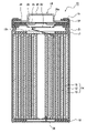
- FIG. 1 is an axial cross-sectional view of a cylindrical secondary battery that is an example of an embodiment
- FIG. 1 is a cross-sectional view of a negative electrode in one example of an embodiment
- FIG. It is a schematic diagram showing a cross section of a graphite particle in an example of the embodiment.
- FIG. 1 is an axial cross-sectional view of a cylindrical secondary battery 10 that is an example of an embodiment.
- an electrode body 14 and a non-aqueous electrolyte (not shown) are housed in an exterior body 15 .
- the electrode body 14 has a wound structure in which the positive electrode 11 and the negative electrode 12 are wound with the separator 13 interposed therebetween.
- the sealing member 16 side will be referred to as "upper”
- the bottom side of the outer package 15 will be referred to as "lower”.
- the inside of the secondary battery 10 is hermetically sealed by closing the opening end of the exterior body 15 with the sealing body 16 .
- Insulating plates 17 and 18 are provided above and below the electrode body 14, respectively.
- the positive electrode lead 19 extends upward through the through hole of the insulating plate 17 and is welded to the lower surface of the filter 22 which is the bottom plate of the sealing member 16 .
- the cap 26, which is the top plate of the sealing member 16 electrically connected to the filter 22, serves as a positive electrode terminal.
- the negative electrode lead 20 passes through the through hole of the insulating plate 18 , extends to the bottom side of the exterior body 15 , and is welded to the bottom inner surface of the exterior body 15 .
- the exterior body 15 becomes a negative electrode terminal.
- the negative electrode lead 20 When the negative electrode lead 20 is installed at the terminal end, the negative electrode lead 20 extends through the outside of the insulating plate 18 toward the bottom of the package 15 and is welded to the inner surface of the bottom of the package 15 .
- the exterior body 15 is, for example, a bottomed cylindrical metal exterior can.
- a gasket 27 is provided between the exterior body 15 and the sealing body 16 to ensure hermetic sealing of the inside of the secondary battery 10 .
- the exterior body 15 has a grooved portion 21 that supports the sealing body 16 and is formed, for example, by pressing the side portion from the outside.
- the grooved portion 21 is preferably annularly formed along the circumferential direction of the exterior body 15 and supports the sealing body 16 via a gasket 27 on its upper surface.
- the sealing body 16 has a filter 22, a lower valve body 23, an insulating member 24, an upper valve body 25, and a cap 26 which are stacked in order from the electrode body 14 side.
- Each member constituting the sealing member 16 has, for example, a disk shape or a ring shape, and each member other than the insulating member 24 is electrically connected to each other.
- the lower valve body 23 and the upper valve body 25 are connected to each other at their central portions, and an insulating member 24 is interposed between their peripheral edge portions.
- the positive electrode 11, the negative electrode 12, the separator 13, and the non-aqueous electrolyte that constitute the secondary battery 10, in particular the negative electrode mixture layer 32 that constitutes the negative electrode 12, will be described in detail below.
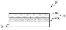
- FIG. 2 is a cross-sectional view of the negative electrode 12 that is an example of an embodiment.
- the negative electrode 12 includes a negative electrode current collector 30 and a negative electrode mixture layer 32 formed on the surface of the negative electrode current collector 30 .
- the negative electrode mixture layer 32 includes a first negative electrode mixture layer 32a facing the negative electrode current collector 30 and a second negative electrode mixture layer 32b laminated on the surface of the first negative electrode mixture layer 32a.
- the thickness of the first negative electrode mixture layer 32a and the thickness of the second negative electrode mixture layer 32b may be the same or different.
- the thickness ratio between the first negative electrode mixture layer 32a and the second negative electrode mixture layer 32b is, for example, 3:7 to 7:3, preferably 4:6 to 6:4, and 5:5 to 6:4. is more preferred.
- the negative electrode current collector 30 for example, a foil of a metal such as copper that is stable in the potential range of the negative electrode, a film having the metal on the surface layer, or the like is used.
- the thickness of the negative electrode current collector 30 is, for example, 5 ⁇ m to 30 ⁇ m.
- the negative electrode mixture layer 32 contains graphite particles as a negative electrode active material.
- graphite particles include natural graphite and artificial graphite. Artificial graphite is preferable in terms of ease of adjustment of internal porosity, which will be described later.
- the interplanar spacing (d 002 ) of the (002) plane of the graphite particles according to the X-ray wide-angle diffraction method is, for example, preferably 0.3354 nm or more, more preferably 0.3357 nm or more, and 0.340 nm. It is preferably less than 0.338 nm, more preferably 0.338 nm or less.
- the crystallite size (Lc(002)) of the graphite particles obtained by the X-ray diffraction method is, for example, preferably 5 nm or more, more preferably 10 nm or more, and 300 nm or less. It is preferably 200 nm or less, more preferably 200 nm or less.
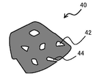
- FIG. 3 is a schematic diagram showing a cross section of the graphite particles 40.
- FIG. 3 in a cross-sectional view of the graphite particle 40, the graphite particle 40 has closed voids 42 that are not connected from the inside of the particle to the particle surface (hereinafter referred to as internal voids 42) and voids that are connected from the inside of the particle to the particle surface. and a gap 44 (hereinafter referred to as an external gap 44).
- the porosity between graphite particles in the second negative electrode mixture layer 32b is higher than the porosity between graphite particles in the first negative electrode mixture layer 32a.
- the ratio (S2/S1) of the void ratio (S2) between graphite particles in the second negative electrode mixture layer 32b to the void ratio (S1) between graphite particles in the first negative electrode mixture layer 32a is 1 ⁇ S2/S1 ⁇ 2 is preferable, 1.1 ⁇ S2/S1 ⁇ 1.7 is more preferable, and 1.1 ⁇ S2/S1 ⁇ 1.5 is particularly preferable.
- S2/S1 ⁇ 1 the permeability of the non-aqueous electrolyte in the second negative electrode mixture layer 32b becomes poor, and the battery capacity decreases due to repeated charging and discharging.
- the void ratio between graphite particles is a two-dimensional value obtained from the ratio of the area of voids between graphite particles to the cross-sectional area of the negative electrode mixture layer 32 .
- S2/S1 calculates the void ratio (S1) between graphite particles in the first negative electrode mixture layer 32a and the void ratio (S2) between graphite particles in the second negative electrode mixture layer 32b in the following procedure. It is required by
- ⁇ Method for measuring porosity between graphite particles> Exposing a cross section of the negative electrode mixture layer. Examples of the method for exposing the cross section include a method in which a portion of the negative electrode is cut and processed with an ion milling device (eg, IM4000PLUS manufactured by Hitachi High-Tech) to expose the cross section of the negative electrode mixture layer.
- an ion milling device eg, IM4000PLUS manufactured by Hitachi High-Tech
- Backscattered electron images of cross sections of the exposed negative electrode mixture layers are taken for each of the first negative electrode mixture layer 32a and the second negative electrode mixture layer 32b using a scanning electron microscope. The magnification for capturing the backscattered electron image is, for example, 800 times.
- the cross-sectional image obtained as described above is taken into a computer, and subjected to binarization processing using image analysis software (for example, ImageJ manufactured by the National Institutes of Health, USA) to turn the particle cross section in the cross-sectional image black, A binarized image is obtained in which voids present in the cross section of the particle are converted to white.
- image analysis software for example, ImageJ manufactured by the National Institutes of Health, USA
- a binarized image is obtained in which voids present in the cross section of the particle are converted to white.
- the internal voids 42 and the external voids 44 having a width of 3 ⁇ m or less
- the area of the voids between the graphite particles is calculated by regarding the portions other than the voids between the graphite particles as voids between the graphite particles.
- Means for adjusting the porosity between graphite particles in the first negative electrode mixture layer 32a and the second negative electrode mixture layer 32b include, for example, means for adjusting the packing density of the negative electrode mixture layer and internal porosity of the graphite particles. can be adjusted. According to the latter means, by reducing the internal porosity of the graphite particles, the porosity between the graphite particles can be reduced without reducing the packing density of the first negative electrode mixture layer 32a and the second negative electrode mixture layer 32b. can be enhanced.
- the second negative electrode mixture layer By reducing the internal porosity of the graphite particles B contained in 32b, S2/S1>1 can be satisfied.
- the graphite particles A contained in the first negative electrode mixture layer 32a can be produced, for example, as follows. Coke (precursor), which is the main raw material, is pulverized to a predetermined size, agglomerated with a binder, and further pressure-molded into a block shape, which is fired at a temperature of 2600° C. or higher to graphitize. Graphite particles A having a desired size are obtained by pulverizing and sieving the block-shaped compact after graphitization. Here, it is possible to adjust the internal porosity to be larger than that of graphite particles B, which will be described later, by adjusting the amount of the volatile component added to the block-shaped compact.
- the internal porosity of graphite particles A is preferably 8% to 20%, more preferably 10% to 18%, and particularly preferably 12% to 16%. If part of the binder added to the coke (precursor) volatilizes during firing, the binder can be used as a volatile component. Pitch is exemplified as such a binder.
- the graphite particles B contained in the second negative electrode mixture layer 32b can be produced, for example, as follows. Coke (precursor), which is the main raw material, is pulverized to a predetermined size, aggregated with a binder, fired at a temperature of 2600 ° C. or higher, graphitized, and sieved to obtain the desired Graphite particles B of size are obtained.
- the internal porosity of the graphite particles B can be adjusted by the particle size of the precursor after pulverization, the particle size of the aggregated precursor, and the like. For example, the internal porosity can be reduced by increasing the particle size of the precursor after pulverization.
- the average particle diameter of the pulverized precursor may be in the range of 12 ⁇ m to 20 ⁇ m.
- the internal porosity of the graphite particles B is preferably 5% or less, more preferably 1% to 5%, particularly preferably 3% to 5%.
- first negative electrode mixture layer 32a and the second negative electrode mixture layer 32b a method for forming the first negative electrode mixture layer 32a and the second negative electrode mixture layer 32b will be described.
- a negative electrode active material containing graphite particles A, a binder, and a solvent such as water are mixed to prepare a first negative electrode mixture slurry.
- a negative electrode active material containing graphite particles B, a binder, and a solvent such as water are mixed to prepare a second negative electrode mixture slurry.
- the second negative electrode mixture slurry is applied to both surfaces of the coating film of the first negative electrode mixture slurry and dried.
- the negative electrode mixture layer 32 can be formed by rolling the first negative electrode mixture layer 32a and the second negative electrode mixture layer 32b with rolling rollers.
- the first negative electrode mixture slurry is applied and dried, and then the second negative electrode mixture slurry is applied.
- a slurry may be applied.
- the first negative electrode mixture slurry may be applied, dried, and rolled, and then the second negative electrode mixture slurry may be applied on the first negative electrode mixture layer 32a.
- the negative electrode mixture layer 32 further contains a high dielectric material with a higher dielectric constant than graphite particles.
- the content of the high dielectric material in the first negative electrode mixture layer 32a is higher than the content of the high dielectric material in the second negative electrode mixture layer 32b. While S2/S1>1, the content of the high dielectric material in the first negative electrode mixture layer 32a is higher than the content of the high dielectric material in the second negative electrode mixture layer 32b. Since the permeability of the non-aqueous electrolyte in the opposing first negative electrode mixture layers 32 a is improved, the permeability of the non-aqueous electrolyte in the entire negative electrode mixture layer 32 is improved. This improves the charge/discharge cycle characteristics of the battery.
- the content of the high dielectric material is the ratio of the mass of the high dielectric material to the mass of the negative electrode active material.
- the high dielectric material is not particularly limited as long as it has a dielectric constant higher than that of graphite particles, and examples thereof include titanium oxide (TiO 2 ), lithium titanate (Li 2 TiO 3 ) and barium oxide (BaO).
- the high dielectric material preferably contains at least one of titanium oxide (TiO 2 ) and lithium titanate (Li 2 TiO 3 ).
- the dielectric constant of graphite particles is about 12, the dielectric constant of TiO2 is about 100, and the dielectric constant of Li2TiO3 is about 30 .
- the average particle size (D50) of the high dielectric material is, for example, 300 nm to 3 ⁇ m.
- the content of the high dielectric material in the first negative electrode mixture layer 32a is preferably 1% by mass to 10% by mass, more preferably 2% by mass, with respect to the mass of the negative electrode active material contained in the first negative electrode mixture layer 32a. % to 7% by mass, and particularly preferably 2.5% to 5% by mass. Within this range, a decrease in battery capacity can be suppressed while improving charge-discharge cycle characteristics.
- the negative electrode mixture layer 32 may further contain a Si-based material as a negative electrode active material.
- a Si-based material is a material that can reversibly absorb and release lithium ions, and functions as a negative electrode active material. Examples of Si-based materials include Si, alloys containing Si, and silicon oxides such as SiO x (where x is 0.8 to 1.6).
- a Si-based material is a negative electrode material that can improve battery capacity more than graphite particles.
- the content of the Si-based material is, for example, preferably 1% by mass to 10% by mass with respect to the mass of the negative electrode active material, from the viewpoint of improving battery capacity, suppressing deterioration of charge-discharge cycle characteristics, etc., and 3% by mass. % to 7 mass %.
- the negative electrode active material may contain the above other materials, and the content of the above other materials is preferably, for example, 10% by mass or less with respect to the mass of the negative electrode active material.
- the negative electrode mixture layer 32 may contain a binder.
- binders include fluorine-based resins, PAN, polyimide-based resins, acrylic-based resins, polyolefin-based resins, styrene-butadiene rubber (SBR), nitrile-butadiene rubber (NBR), carboxymethylcellulose (CMC), or salts thereof.
- polyacrylic acid (PAA) or salts thereof (PAA-Na, PAA-K, etc., and partially neutralized salts may also be used), polyvinyl alcohol (PVA), and the like. These may be used alone or in combination of two or more.
- the positive electrode 11 is composed of, for example, a positive electrode current collector such as a metal foil, and a positive electrode mixture layer formed on the positive electrode current collector.
- a positive electrode current collector such as a metal foil
- a positive electrode mixture layer formed on the positive electrode current collector.
- the positive electrode current collector a foil of a metal such as aluminum that is stable in the positive electrode potential range, a film having the metal on the surface layer, or the like can be used.
- the positive electrode mixture layer contains, for example, a positive electrode active material, a binder, a conductive agent, and the like.
- a positive electrode mixture slurry containing a positive electrode active material, a binder, a conductive agent, etc. is applied onto a positive electrode current collector and dried to form a positive electrode mixture layer. It can be produced by rolling.
- Examples of positive electrode active materials include lithium transition metal oxides containing transition metal elements such as Co, Mn, and Ni.
- Lithium transition metal oxides include, for example, Li x CoO 2 , Li x NiO 2 , Li x MnO 2 , Li x Co y Ni 1-y O 2 , Li x Co y M 1-y O z , Li x Ni 1- yMyOz , LixMn2O4 , LixMn2 - yMyO4 , LiMPO4 , Li2MPO4F ( M ; Na , Mg , Sc , Y , Mn, Fe, Co, Ni , Cu, Zn, Al, Cr, Pb, Sb, and B, 0 ⁇ x ⁇ 1.2, 0 ⁇ y ⁇ 0.9, 2.0 ⁇ z ⁇ 2.3).
- the positive electrode active material is Li x NiO 2 , Li x Co y Ni 1-y O 2 , Li x Ni 1- y My O z ( M; at least one of Na, Mg, Sc, Y, Mn, Fe, Co, Ni, Cu, Zn, Al, Cr, Pb, Sb, and B, 0 ⁇ x ⁇ 1.2, 0 ⁇ y ⁇ 0 .9, 2.0 ⁇ z ⁇ 2.3).
- Conductive agents include, for example, carbon black (CB), acetylene black (AB), ketjen black, carbon nanotubes (CNT), graphene, and carbon-based particles such as graphite. These may be used alone or in combination of two or more.
- binders include fluorine-based resins such as polytetrafluoroethylene (PTFE) and polyvinylidene fluoride (PVdF), polyacrylonitrile (PAN), polyimide-based resins, acrylic-based resins, and polyolefin-based resins. These may be used alone or in combination of two or more.
- fluorine-based resins such as polytetrafluoroethylene (PTFE) and polyvinylidene fluoride (PVdF), polyacrylonitrile (PAN), polyimide-based resins, acrylic-based resins, and polyolefin-based resins. These may be used alone or in combination of two or more.
- separator 13 for example, a porous sheet or the like having ion permeability and insulation is used. Specific examples of porous sheets include microporous thin films, woven fabrics, and non-woven fabrics. Suitable materials for the separator include olefin resins such as polyethylene and polypropylene, and cellulose.
- the separator 13 may be a laminate having a cellulose fiber layer and a thermoplastic resin fiber layer such as an olefin resin. Also, a multilayer separator including a polyethylene layer and a polypropylene layer may be used, and a separator 13 having a surface coated with a material such as aramid resin or ceramic may be used.
- a non-aqueous electrolyte is a liquid electrolyte (electrolytic solution) containing a non-aqueous solvent and an electrolyte salt dissolved in the non-aqueous solvent.
- non-aqueous solvents examples include esters, ethers, nitriles such as acetonitrile, amides such as dimethylformamide, and mixed solvents of two or more thereof.
- the non-aqueous solvent may contain a halogen-substituted product obtained by substituting at least part of the hydrogen atoms of these solvents with halogen atoms such as fluorine.
- esters examples include cyclic carbonates such as ethylene carbonate (EC), propylene carbonate (PC) and butylene carbonate, dimethyl carbonate (DMC), ethyl methyl carbonate (EMC), diethyl carbonate (DEC), methyl propyl carbonate. , Ethyl propyl carbonate, methyl isopropyl carbonate and other chain carbonates, ⁇ -butyrolactone, ⁇ -valerolactone and other cyclic carboxylic acid esters, methyl acetate, ethyl acetate, propyl acetate, methyl propionate (MP), ethyl propionate, etc. and chain carboxylic acid esters of.
- cyclic carbonates such as ethylene carbonate (EC), propylene carbonate (PC) and butylene carbonate, dimethyl carbonate (DMC), ethyl methyl carbonate (EMC), diethyl carbonate (DEC), methyl propyl carbonate.
- ethers examples include 1,3-dioxolane, 4-methyl-1,3-dioxolane, tetrahydrofuran, 2-methyltetrahydrofuran, propylene oxide, 1,2-butylene oxide, 1,3-dioxane, 1,4 - Cyclic ethers such as dioxane, 1,3,5-trioxane, furan, 2-methylfuran, 1,8-cineol, crown ether, 1,2-dimethoxyethane, diethyl ether, dipropyl ether, diisopropyl ether, dibutyl ether , dihexyl ether, ethyl vinyl ether, butyl vinyl ether, methyl phenyl ether, ethyl phenyl ether, butyl phenyl ether, pentyl phenyl ether, methoxytoluene, benzyl ethyl ether, diphenyl ether, dipheny
- a fluorinated cyclic carbonate such as fluoroethylene carbonate (FEC), a fluorinated chain carbonate, a fluorinated chain carboxylate such as methyl fluoropropionate (FMP), and the like.
- FEC fluoroethylene carbonate
- FMP fluorinated chain carboxylate
- FEC fluoroethylene carbonate
- FMP fluorinated chain carboxylate
- the electrolyte salt is a lithium salt.
- lithium salts include LiBF4 , LiClO4, LiPF6 , LiAsF6 , LiSbF6 , LiAlCl4 , LiSCN , LiCF3SO3 , LiCF3CO2 , Li ( P ( C2O4 ) F4 ), LiPF 6-x (C n F 2n+1 ) x (1 ⁇ x ⁇ 6, n is 1 or 2), LiB 10 Cl 10 , LiCl, LiBr, LiI, lithium chloroborane, lithium lower aliphatic carboxylate, Li 2 B 4O7 , borates such as Li( B ( C2O4 )F2), LiN( SO2CF3 ) 2 , LiN( C1F2l + 1SO2 ) ( CmF2m +1SO2 ) ⁇ l , where m is an integer of 1 or more ⁇ .
- Lithium salts may be used singly or in combination. Of these, it is preferable to use LiPF 6 from the viewpoint of ion conductivity, electrochemical stability, and the like.
- the lithium salt concentration is preferably 0.8 to 1.8 mol per 1 L of solvent.
- Example 1 [Preparation of positive electrode]
- Aluminum-containing lithium nickel cobaltate (LiNi 0.88 Co 0.09 Al 0.03 O 2 ) was used as the positive electrode active material. 100 parts by mass of the positive electrode active material, 1 part by mass of graphite as a conductive agent, and 0.9 parts by mass of polyvinylidene fluoride powder as a binder are mixed, and further N-methyl-2-pyrrolidone (NMP ) was added to prepare a positive electrode mixture slurry.
- NMP N-methyl-2-pyrrolidone
- This slurry is applied to both sides of a positive electrode current collector made of aluminum foil (thickness 15 ⁇ m) by a doctor blade method, the coating film is dried, and then the coating film is rolled with a rolling roller to A positive electrode having a positive electrode mixture layer formed thereon was produced.
- a negative electrode active material A 95 parts by mass of graphite particles A and 5 parts by mass of SiO were mixed to obtain a negative electrode active material A. Titanium oxide (TiO 2 ) having an average particle size (D50) of 500 nm was used as the high dielectric material.
- Negative electrode active material A TiO 2 : carboxymethyl cellulose (CMC): styrene-butadiene copolymer rubber (SBR) were mixed so that the mass ratio was 100:2.5:1:1, and the mixture was The mixture was kneaded in water to prepare a first negative electrode mixture slurry. Further, 95 parts by mass of graphite particles B and 5 parts by mass of SiO were mixed to obtain a negative electrode active material B.
- CMC carboxymethyl cellulose
- SBR styrene-butadiene copolymer rubber
- Negative electrode active material B carboxymethyl cellulose (CMC): styrene-butadiene copolymer rubber (SBR) were mixed so that the mass ratio was 100:1:1, and the mixture was kneaded in water to obtain a second A two-negative electrode mixture slurry was prepared.
- CMC carboxymethyl cellulose
- SBR styrene-butadiene copolymer rubber
- the first negative electrode mixture slurry was applied to both sides of a negative electrode current collector made of copper foil by a doctor blade method and dried to form a first negative electrode mixture layer. Furthermore, the second negative electrode mixture slurry was applied onto the first negative electrode mixture layer and dried to form a second negative electrode mixture layer. At this time, the coating mass ratio per unit area of the first negative electrode mixture slurry and the second negative electrode mixture slurry was set to 5:5.
- a negative electrode was produced by rolling the first negative electrode mixture layer and the second negative electrode mixture layer with a rolling roller.
- VC vinylene carbonate
- EC ethylene carbonate
- dimethyl carbonate a non-aqueous solvent obtained by mixing ethylene carbonate (EC) and dimethyl carbonate at a volume ratio of 1: 3 . It was dissolved at a concentration of 5 mol/L and used as a non-aqueous electrolyte.
- Non-aqueous electrolyte secondary battery (1) After attaching the positive electrode lead to the positive electrode current collector and attaching the negative electrode lead to the negative electrode current collector, the positive electrode and the negative electrode are wound with a separator made of a microporous polyethylene film interposed therebetween, and the winding type is obtained. An electrode body was produced. (2) Insulating plates were placed above and below the electrode assembly, the negative electrode lead was welded to the outer package, the positive electrode lead was welded to the sealing member, and the electrode assembly was housed in the outer package. (3) After injecting the non-aqueous electrolyte into the exterior body by a depressurization method, the opening of the exterior body was sealed with a sealant via a gasket to obtain a non-aqueous electrolyte secondary battery.
- Non-aqueous electrolyte 2 was prepared in the same manner as in Example 1, except that the content of TiO 2 contained in the first negative electrode mixture slurry was 3% by mass with respect to the mass of negative electrode active material A in the production of the negative electrode. made the next battery
- Non-aqueous electrolyte 2 was prepared in the same manner as in Example 1, except that the content of TiO 2 contained in the first negative electrode mixture slurry was 5% by mass with respect to the mass of negative electrode active material A in the production of the negative electrode. A following battery was produced.
- Example 1 A non-aqueous electrolyte secondary battery was fabricated in the same manner as in Example 1, except that TiO 2 was not added to the first negative electrode mixture slurry in fabricating the negative electrode.
- Table 1 summarizes the evaluation results of the capacity retention rate of the non-aqueous electrolyte secondary batteries of each example and each comparative example. Table 1 also shows the graphite particles contained in the first and second negative electrode mixture layers, the content of TiO2 in the first and second negative electrode mixture layers, and the content of TiO2 in the negative electrode mixture layer. S2/S1 is also shown.
- the battery of the example has an improved capacity retention rate compared to the battery of the comparative example.
- the porosity between graphite particles in the second negative electrode mixture layer is high, and the first negative electrode mixture layer contains titanium oxide having a dielectric constant higher than that of graphite. It is considered that the capacity retention rate was improved because the permeability of the entire layer to the electrolytic solution was improved.
Landscapes
- Chemical & Material Sciences (AREA)
- Chemical Kinetics & Catalysis (AREA)
- Electrochemistry (AREA)
- General Chemical & Material Sciences (AREA)
- Engineering & Computer Science (AREA)
- Materials Engineering (AREA)
- Composite Materials (AREA)
- Inorganic Chemistry (AREA)
- Manufacturing & Machinery (AREA)
- Battery Electrode And Active Subsutance (AREA)
- Secondary Cells (AREA)
Abstract
Priority Applications (4)
| Application Number | Priority Date | Filing Date | Title |
|---|---|---|---|
| JP2022576637A JPWO2022158375A1 (fr) | 2021-01-21 | 2022-01-14 | |
| EP22742497.5A EP4283702A1 (fr) | 2021-01-21 | 2022-01-14 | Batterie secondaire à électrolyte non aqueux |
| CN202280009459.0A CN116711098A (zh) | 2021-01-21 | 2022-01-14 | 非水电解质二次电池 |
| US18/271,757 US20240063377A1 (en) | 2021-01-21 | 2022-01-14 | Non-aqueous electrolyte secondary battery |
Applications Claiming Priority (2)
| Application Number | Priority Date | Filing Date | Title |
|---|---|---|---|
| JP2021007957 | 2021-01-21 | ||
| JP2021-007957 | 2021-01-21 |
Publications (1)
| Publication Number | Publication Date |
|---|---|
| WO2022158375A1 true WO2022158375A1 (fr) | 2022-07-28 |
Family
ID=82549006
Family Applications (1)
| Application Number | Title | Priority Date | Filing Date |
|---|---|---|---|
| PCT/JP2022/001019 WO2022158375A1 (fr) | 2021-01-21 | 2022-01-14 | Batterie secondaire à électrolyte non aqueux |
Country Status (5)
| Country | Link |
|---|---|
| US (1) | US20240063377A1 (fr) |
| EP (1) | EP4283702A1 (fr) |
| JP (1) | JPWO2022158375A1 (fr) |
| CN (1) | CN116711098A (fr) |
| WO (1) | WO2022158375A1 (fr) |
Citations (4)
| Publication number | Priority date | Publication date | Assignee | Title |
|---|---|---|---|---|
| JP2008027879A (ja) | 2006-06-19 | 2008-02-07 | Hitachi Maxell Ltd | リチウム二次電池用電極およびリチウム二次電池 |
| JP2015511389A (ja) * | 2013-01-25 | 2015-04-16 | エルジー・ケム・リミテッド | リチウム二次電池用負極及びこれを含むリチウム二次電池 |
| WO2016035289A1 (fr) * | 2014-09-05 | 2016-03-10 | 三洋電機株式会社 | Electrode négative pour batteries secondaires à électrolyte non aqueux et batterie secondaire à électrolyte non aqueux |
| JP2020095853A (ja) * | 2018-12-12 | 2020-06-18 | トヨタ自動車株式会社 | 非水電解質二次電池 |
-
2022
- 2022-01-14 WO PCT/JP2022/001019 patent/WO2022158375A1/fr active Application Filing
- 2022-01-14 EP EP22742497.5A patent/EP4283702A1/fr active Pending
- 2022-01-14 CN CN202280009459.0A patent/CN116711098A/zh active Pending
- 2022-01-14 JP JP2022576637A patent/JPWO2022158375A1/ja active Pending
- 2022-01-14 US US18/271,757 patent/US20240063377A1/en active Pending
Patent Citations (4)
| Publication number | Priority date | Publication date | Assignee | Title |
|---|---|---|---|---|
| JP2008027879A (ja) | 2006-06-19 | 2008-02-07 | Hitachi Maxell Ltd | リチウム二次電池用電極およびリチウム二次電池 |
| JP2015511389A (ja) * | 2013-01-25 | 2015-04-16 | エルジー・ケム・リミテッド | リチウム二次電池用負極及びこれを含むリチウム二次電池 |
| WO2016035289A1 (fr) * | 2014-09-05 | 2016-03-10 | 三洋電機株式会社 | Electrode négative pour batteries secondaires à électrolyte non aqueux et batterie secondaire à électrolyte non aqueux |
| JP2020095853A (ja) * | 2018-12-12 | 2020-06-18 | トヨタ自動車株式会社 | 非水電解質二次電池 |
Also Published As
| Publication number | Publication date |
|---|---|
| EP4283702A1 (fr) | 2023-11-29 |
| JPWO2022158375A1 (fr) | 2022-07-28 |
| CN116711098A (zh) | 2023-09-05 |
| US20240063377A1 (en) | 2024-02-22 |
Similar Documents
| Publication | Publication Date | Title |
|---|---|---|
| JP7319265B2 (ja) | 非水電解質二次電池 | |
| JPWO2020175361A1 (ja) | 非水電解質二次電池 | |
| JP7336736B2 (ja) | 非水電解質二次電池 | |
| WO2022181489A1 (fr) | Électrode négative pour batteries secondaires à électrolyte non aqueux, et batterie secondaire à électrolyte non aqueux | |
| WO2021117480A1 (fr) | Batterie secondaire à électrolyte non aqueux | |
| US20230335711A1 (en) | Positive electrode active material for nonaqueous electrolyte secondary batteries, and nonaqueous electrolyte secondary battery | |
| WO2021106730A1 (fr) | Batterie secondaire à électrolyte non aqueux | |
| JP7233013B2 (ja) | 非水電解質二次電池 | |
| WO2023053625A1 (fr) | Batterie rechargeable à électrolyte non aqueux | |
| US20230378448A1 (en) | Negative electrode for secondary batteries, and secondary battery | |
| JP7300658B2 (ja) | 非水電解質二次電池用正極活物質、及び非水電解質二次電池 | |
| CN116195086A (zh) | 二次电池用负极和二次电池 | |
| WO2022158375A1 (fr) | Batterie secondaire à électrolyte non aqueux | |
| WO2023157746A1 (fr) | Batterie secondaire à électrolyte non aqueux | |
| WO2024004836A1 (fr) | Batterie secondaire à électrolyte non aqueux | |
| WO2021117615A1 (fr) | Batterie secondaire à électrolyte non aqueux | |
| WO2023149529A1 (fr) | Batterie secondaire à électrolyte non aqueux | |
| WO2024004837A1 (fr) | Électrode négative pour batteries secondaires à électrolyte non aqueux, et batterie secondaire à électrolyte non aqueux | |
| WO2021117748A1 (fr) | Batterie secondaire à électrolyte non aqueux | |
| WO2023276582A1 (fr) | Batterie secondaire à électrolyte non aqueux | |
| WO2023210584A1 (fr) | Batterie rechargeable à électrolyte non aqueux | |
| WO2023053626A1 (fr) | Batterie secondaire à électrolyte non aqueux | |
| WO2024024505A1 (fr) | Électrode négative pour batteries secondaires à électrolyte non aqueux, et batterie secondaire à électrolyte non aqueux | |
| WO2021106727A1 (fr) | Électrode négative pour batteries secondaires à électrolyte non aqueux, batterie secondaire à électrolyte non aqueux, et procédé de production d'électrode négative pour batteries secondaires à électrolyte non aqueux | |
| WO2023176503A1 (fr) | Batterie secondaire à électrolyte non aqueux |
Legal Events
| Date | Code | Title | Description |
|---|---|---|---|
| 121 | Ep: the epo has been informed by wipo that ep was designated in this application |
Ref document number: 22742497 Country of ref document: EP Kind code of ref document: A1 |
|
| ENP | Entry into the national phase |
Ref document number: 2022576637 Country of ref document: JP Kind code of ref document: A |
|
| WWE | Wipo information: entry into national phase |
Ref document number: 202280009459.0 Country of ref document: CN |
|
| WWE | Wipo information: entry into national phase |
Ref document number: 18271757 Country of ref document: US |
|
| NENP | Non-entry into the national phase |
Ref country code: DE |
|
| ENP | Entry into the national phase |
Ref document number: 2022742497 Country of ref document: EP Effective date: 20230821 |