WO2022181036A1 - サウンドゾーニングシステム - Google Patents
サウンドゾーニングシステム Download PDFInfo
- Publication number
- WO2022181036A1 WO2022181036A1 PCT/JP2021/048135 JP2021048135W WO2022181036A1 WO 2022181036 A1 WO2022181036 A1 WO 2022181036A1 JP 2021048135 W JP2021048135 W JP 2021048135W WO 2022181036 A1 WO2022181036 A1 WO 2022181036A1
- Authority
- WO
- WIPO (PCT)
- Prior art keywords
- sound
- speaker
- speaker devices
- khz
- zone
- Prior art date
- Legal status (The legal status is an assumption and is not a legal conclusion. Google has not performed a legal analysis and makes no representation as to the accuracy of the status listed.)
- Ceased
Links
Images



Classifications
-
- H—ELECTRICITY
- H04—ELECTRIC COMMUNICATION TECHNIQUE
- H04R—LOUDSPEAKERS, MICROPHONES, GRAMOPHONE PICK-UPS OR LIKE ACOUSTIC ELECTROMECHANICAL TRANSDUCERS; ELECTRIC HEARING AIDS; PUBLIC ADDRESS SYSTEMS
- H04R1/00—Details of transducers, loudspeakers or microphones
- H04R1/02—Casings; Cabinets ; Supports therefor; Mountings therein
-
- H—ELECTRICITY
- H04—ELECTRIC COMMUNICATION TECHNIQUE
- H04R—LOUDSPEAKERS, MICROPHONES, GRAMOPHONE PICK-UPS OR LIKE ACOUSTIC ELECTROMECHANICAL TRANSDUCERS; ELECTRIC HEARING AIDS; PUBLIC ADDRESS SYSTEMS
- H04R1/00—Details of transducers, loudspeakers or microphones
- H04R1/20—Arrangements for obtaining desired frequency or directional characteristics
- H04R1/22—Arrangements for obtaining desired frequency or directional characteristics for obtaining desired frequency characteristic only
- H04R1/30—Combinations of transducers with horns, e.g. with mechanical matching means, i.e. front-loaded horns
-
- H—ELECTRICITY
- H04—ELECTRIC COMMUNICATION TECHNIQUE
- H04R—LOUDSPEAKERS, MICROPHONES, GRAMOPHONE PICK-UPS OR LIKE ACOUSTIC ELECTROMECHANICAL TRANSDUCERS; ELECTRIC HEARING AIDS; PUBLIC ADDRESS SYSTEMS
- H04R1/00—Details of transducers, loudspeakers or microphones
- H04R1/20—Arrangements for obtaining desired frequency or directional characteristics
- H04R1/32—Arrangements for obtaining desired frequency or directional characteristics for obtaining desired directional characteristic only
-
- H—ELECTRICITY
- H04—ELECTRIC COMMUNICATION TECHNIQUE
- H04R—LOUDSPEAKERS, MICROPHONES, GRAMOPHONE PICK-UPS OR LIKE ACOUSTIC ELECTROMECHANICAL TRANSDUCERS; ELECTRIC HEARING AIDS; PUBLIC ADDRESS SYSTEMS
- H04R27/00—Public address systems
-
- H—ELECTRICITY
- H04—ELECTRIC COMMUNICATION TECHNIQUE
- H04R—LOUDSPEAKERS, MICROPHONES, GRAMOPHONE PICK-UPS OR LIKE ACOUSTIC ELECTROMECHANICAL TRANSDUCERS; ELECTRIC HEARING AIDS; PUBLIC ADDRESS SYSTEMS
- H04R3/00—Circuits for transducers
-
- Y—GENERAL TAGGING OF NEW TECHNOLOGICAL DEVELOPMENTS; GENERAL TAGGING OF CROSS-SECTIONAL TECHNOLOGIES SPANNING OVER SEVERAL SECTIONS OF THE IPC; TECHNICAL SUBJECTS COVERED BY FORMER USPC CROSS-REFERENCE ART COLLECTIONS [XRACs] AND DIGESTS
- Y02—TECHNOLOGIES OR APPLICATIONS FOR MITIGATION OR ADAPTATION AGAINST CLIMATE CHANGE
- Y02B—CLIMATE CHANGE MITIGATION TECHNOLOGIES RELATED TO BUILDINGS, e.g. HOUSING, HOUSE APPLIANCES OR RELATED END-USER APPLICATIONS
- Y02B20/00—Energy efficient lighting technologies, e.g. halogen lamps or gas discharge lamps
- Y02B20/40—Control techniques providing energy savings, e.g. smart controller or presence detection
Definitions
- the present invention relates to a sound zoning system.
- Patent Document 1 discloses a lighting control device that can determine whether a segmented area obtained by segmenting a lighting area is a stay area where a person stays or a non-stay area, and can perform different lighting control for each determined area.
- the present invention provides a sound zoning system that can easily zone a space.
- a sound zoning system is a sound zoning system that divides a space into a plurality of zones according to what kind of sound content is heard in the space, wherein a first zone among the plurality of zones is and a control device for controlling the plurality of first speaker devices to form the first zone, wherein each of the plurality of first speaker devices has a directivity of 45 degrees or less for sound with a frequency of 3 kHz or more and 5 kHz or less.
- the sound zoning system of the present invention can easily zone the space.
- FIG. 1 is a diagram showing a sound zoning system according to an embodiment.
- 2 is a diagram showing a first speaker device of the sound zoning system of FIG. 1.
- FIG. 3 is a cross-sectional view taken along line III-III of FIG.
- FIG. 4 is a block diagram showing the functional configuration of the sound zoning system of FIG.
- FIG. 5 is a graph showing an example of directivity of sound output from a speaker device according to a comparative example.
- 6 is a graph showing an example of directivity of sound output from the first speaker device of the sound zoning system of FIG. 1.
- FIG. 1 is a diagram showing a sound zoning system according to an embodiment.
- 2 is a diagram showing a first speaker device of the sound zoning system of FIG. 1.
- FIG. 3 is a cross-sectional view taken along line III-III of FIG.
- FIG. 4 is a block diagram showing the functional configuration of the sound zoning system of FIG.
- FIG. 5 is a graph
- each figure is a schematic diagram and is not necessarily strictly illustrated. Moreover, in each figure, the same code
- FIG. 1 is a diagram showing a sound zoning system 1 according to an embodiment. A sound zoning system 1 will be described with reference to FIG.
- the sound zoning system 1 is a system that divides a space 100 into a plurality of zones according to what kind of sound content can be heard in the space 100.
- the sound zoning system 1 is a system that forms a plurality of zones in the space 100 by standardizing what kind of genre sounds can be heard for each zone.
- the sound zoning system 1 includes multiple first speaker devices 10 and multiple second speaker devices 60 .
- a plurality of first speaker devices 10 belong to a first group for forming a first zone 101 among a plurality of zones.
- Each of the plurality of first speaker devices 10 has directivity of 45 degrees or less with respect to sound with a frequency of 3 kHz or more and 5 kHz or less. That is, each of the plurality of first speaker devices 10 has a frequency of 3 kHz or more and 5 kHz or less, which is output from the first speaker device 10, from the direction in which the sound pressure of the sound reaches the maximum value to the maximum value. It has the property that the angle to the direction in which it decreases by 10 dB is 45 degrees.
- the angle of the direction in which the sound pressure becomes 10 dB smaller than the maximum value. are -45 degrees and 45 degrees. That is, at this time, the sound pressure becomes lower than the maximum value by 10 dB or more in the range outside the range of 90 degrees centered at 0 degrees.
- sounds with frequencies around 4 kHz are easily audible to the human ear. That is, each of the plurality of first speaker devices 10 has a directivity of 45 degrees or less with respect to sounds of frequencies that are easily audible to human ears.
- the plurality of first speaker devices 10 are fixed to the ceiling of the space 100 , that is, above, and output sound toward the space 100 .
- the plurality of first speaker devices 10 may be installed on the floor of the space 100, that is, below, or may be installed on the walls, that is, on the sides of the space 100, or may be installed on the ceiling, floor, and wall. , or may be slidably attached to a duct rail (not shown).
- Each of the plurality of first speaker devices 10 reproduces sound content by outputting sound.
- the first zone 101 is formed by reproducing sound content of a similar genre from a plurality of first speaker devices 10 .
- the plurality of second speaker devices 60 belong to a second group for forming a second zone 102 adjacent to the first zone 101 among the plurality of zones.
- Each of the plurality of second speaker devices 60 has a directivity of 45 degrees or less with respect to sound with a frequency of 3 kHz or more and 5 kHz or less.
- each of the plurality of second speaker devices 60 for sound with a frequency of 3 kHz or more and 5 kHz or less output from the second speaker device 60, has a sound pressure from the direction in which the sound pressure of the sound reaches the maximum value to the maximum value. It has the property that the angle to the direction in which it decreases by 10 dB is 45 degrees.
- each of the plurality of second speaker devices 60 also has directivity of 45 degrees or less with respect to sounds of frequencies that are easily audible to human ears.
- a plurality of second speaker devices 60 are fixed to the ceiling of the space 100 , that is, above, and output sound toward the space 100 .
- the plurality of second speaker devices 60 may be installed on the floor of the space 100, that is, below, or may be installed on the walls, that is, on the sides of the space 100, or may be installed on the ceiling, floor, and walls. , or may be slidably attached to a duct rail (not shown).
- Each of the plurality of second speaker devices 60 reproduces sound content by outputting sound.
- the second zone 102 is formed by reproducing sound content of a similar genre from a plurality of second speaker devices 60 .
- the plurality of first speaker devices 10 and the plurality of second speaker devices 60 installed on the ceiling are classified as jazz (more specifically, jazz). sound content), and the plurality of second speaker devices 60 reproduce natural environmental sounds (more specifically, sound content classified as natural environmental sounds).
- the space 100 is formed with a first zone 101 where jazz can be heard and a second zone 102 where natural environmental sounds can be heard.
- Natural environmental sounds are, for example, the sounds of wild birds chirping, the sounds of running water, and the like.
- a virtual boundary line between the first zone 101 and the second zone 102 among the plurality of zones is indicated by a dashed line.
- the zoning effect means, for example, a sense of division in perception of space, and may include an effect that allows a user to easily recognize that a plurality of spaces are different from each other.
- the zoning effect may include an effect of facilitating changes in the user's behavior or flow line as intended by the zoning, with the user's recognition. For example, assume that an arbitrary space is zoned with the intention of making it a space where users can easily perform tasks that require concentration. In this case, it can be said that the zoning effect was exhibited if the user who saw the space used the space mainly for the purpose of performing work requiring concentration.
- the zoning effect includes the subjective effect/feeling of the user, or the effect showing the tendency of the physiological/psychological/biological effects of the user in accordance with the purpose of the zoning when the user actually uses the zoning space. obtain.
- an arbitrary space is zoned with the intention of becoming a space that facilitates work that requires concentration, and that the user uses the space.
- the zoning effect can be obtained. It can be said that it was demonstrated.
- the sound zoning system 1 it is possible to zone the space without using fixtures or furniture. Therefore, it is possible to easily improve the design of the space, and to change the layout of the office instantly under the control of the control device 70 .
- changing the sound content in each space can be accomplished in seconds, for example, and as a result the layout of an office can be changed in seconds.
- Changing the layout of an office by manually moving fixtures or furniture takes 60 minutes, several hours, one day, or even several days. From this point of view, the zoning under the control of the control device 70 can produce a very remarkable effect.
- zoning it is possible to change the layout of the office in a short period such as hourly, daily, monthly, etc., compared to conventional office layout changes by changing the arrangement of fixtures or furniture. is possible.
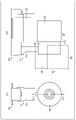
- FIG. 2 is a diagram showing the first speaker device 10 of the sound zoning system 1 of FIG. 2A is a front view of the first speaker device 10, and FIG. 2B is a side view of the first speaker device 10.
- FIG. FIG. 3 is a cross-sectional view taken along line III-III of FIG. The first speaker device 10 will be described with reference to FIGS. 2 and 3.
- FIG. 1 is a diagram showing the first speaker device 10 of the sound zoning system 1 of FIG. 2A is a front view of the first speaker device 10
- FIG. 2B is a side view of the first speaker device 10.
- FIG. FIG. 3 is a cross-sectional view taken along line III-III of FIG. The first speaker device 10 will be described with reference to FIGS. 2 and 3.
- the first speaker device 10 includes a speaker unit 12 and a horn 50.
- FIG. 1 the first speaker device 10 includes a speaker unit 12 and a horn 50.
- the speaker unit 12 has a speaker 16 , a mounting portion 18 , a suspension portion 20 and a reproduction control portion 22 .
- the speaker 16 is a speaker that outputs sound, and has a magnetic circuit 24 , a voice coil body 26 , a damper 28 , a diaphragm 30 , a first frame 32 and a second frame 34 .
- the speaker 16 outputs sound forward (the positive side in the X-axis direction) by vibrating the diaphragm 30 .
- the speaker 16 is attached to the attachment portion 18 with a plurality of screws 23 .
- the magnetic circuit 24 has a magnet 36, a plate 38, and a yoke 40, and generates magnetic flux.
- Magnet 36 is a magnetized permanent magnet.
- the plate 38 has a disk shape and is installed in front of the magnet 36 .
- the yoke 40 is cylindrical with a bottom, accommodates the magnet 36 and the plate 38 , and is connected to the back surface of the magnet 36 .
- plate 38 and yoke 40 are made of a ferromagnetic material such as iron.
- Magnetic circuit 24 forms a magnetic gap between plate 38 and yoke 40 .
- the voice coil body 26 includes a cylindrical bobbin and a coil wound around the bobbin. One end of the voice coil body 26 is located within the magnetic gap formed by the magnetic circuit 24 and the other end of the voice coil body 26 is connected to the diaphragm 30 . When a sound signal is input to the voice coil body 26 , the voice coil body 26 vibrates in the front-rear direction due to the interaction with the magnetic flux generated by the magnetic circuit 24 .
- the damper 28 is connected to the voice coil body 26 and the first frame 32, and supports the voice coil body 26 so as to vibrate in the front-rear direction.
- the diaphragm 30 has a cone shape that gradually widens toward the front, and is connected to the voice coil body 26 and the first frame 32 .
- the diaphragm 30 vibrates based on the sound signal from the reproduction control section 22 and outputs sound forward. Specifically, the diaphragm 30 vibrates when the voice coil body 26 vibrates based on the sound signal from the reproduction control section 22 .
- the reproduction control unit 22 changes the frequency characteristics of the sound signal
- the diaphragm 30 vibrates based on the sound signal whose frequency characteristics have been changed by the reproduction control unit 22 .
- the speaker 16 receives the sound signal processed by the reproduction control unit 22, and the speaker 16 outputs sound based on the input sound signal.
- the first frame 32 has a substantially tubular shape, is connected to the yoke 40 and the second frame 34 , and is a member that fixes the positional relationship between the yoke 40 and the second frame 34 .
- the second frame 34 has a substantially disc shape and is connected to the first frame 32 .
- the second frame 34 is attached to the attachment portion 18 together with the horn 50 by a plurality of screws 23 .
- the speaker 16 is attached to the mounting portion 18 by attaching the second frame 34 to the mounting portion 18 .
- the attachment portion 18 is rotatably attached to the lower end portion of the suspension portion 20 (see arrow Y in FIG. 2(b)).
- a horn 50 is detachably attached to the attachment portion 18 along with the speaker 16 .
- the mounting portion 18 has a plurality of screw holes 42 , and the horn 50 is detachably mounted together with the speaker 16 with a plurality of screws 23 .
- the speaker 16 and the horn 50 can be attached to the mounting portion 18, and by removing the screws 23 from the screw holes 42, the speaker 16 and the horn 50 can be removed from the mounting portion 18. can.
- the suspension part 20 is a member for suspending the speaker 16 and the like from the ceiling, and is slidably supported by, for example, rails (not shown) of the ceiling.
- the reproduction control unit 22 controls sound signals that vibrate the diaphragm 30, and the like.
- the sound signal is stored in advance in the storage unit 54 (described later).
- a sound signal is input from a control device 70 (described later) to the reproduction control unit 22 when sound is output from the speaker 16, and the reproduction control unit 22 controls the reproduction control unit 22 based on the sound signal input from the control device 70.
- a sound signal input from control device 70 is stored in storage unit 54 .
- the playback control section 22 is housed in a housing that constitutes the hanging section 20 .
- the reproduction control unit 22 is configured by a microcomputer, processor, or the like.
- a horn 50 is a horn that corrects the sound output from the speaker 16 .
- the horn 50 corrects the directivity of the sound output from the speaker 16 and having a frequency of 3 kHz or more and 5 kHz or less to 45 degrees or less.
- the horn 50 is cylindrical, opens in the front-rear direction, and is attached to the attachment portion 18 so as to surround the space on the front side of the speaker 16 .
- the horn 50 has an inner surface that gradually widens toward the front. The sound output from the speaker 16 is emitted outside through the horn 50 .
- the axial direction of the horn 50 coincides with the front-rear direction. In other words, the axial direction of the horn 50 coincides with the front-rear direction when the horn 50 is attached to the attachment portion 18 .
- Each of the plurality of first speaker devices 10 has the configuration described above. Further, since each of the plurality of second speaker devices 60 has the same configuration as that of the first speaker device 10 described above, referring to the description of the first speaker device 10 described above, the plurality of second speaker devices 60 can be A detailed description of the speaker device 60 is omitted.
- FIG. 4 is a block diagram showing the functional configuration of the sound zoning system 1 of FIG. A functional configuration of the sound zoning system 1 will be described with reference to FIG.
- the sound zoning system 1 further includes a control device 70 and a wireless communication device 80.
- the control device 70 controls the plurality of first speaker devices 10 to form the first zone 101 by performing wireless communication with each of the plurality of first speaker devices 10 .
- the control device 70 causes the plurality of first speaker devices 10 to synchronously reproduce the same sound content to form the first zone 101 . That is, for example, the control device 70 causes the plurality of first speaker devices 10 to output the same sound at the same timing to form the first zone 101 .
- the control device 70 may cause the plurality of first speaker devices 10 to output the same sound at different timings depending on the locations where the plurality of first speaker devices 10 are installed.
- the control device 70 may cause the plurality of first speaker devices 10 to output different sounds when reproducing natural environmental sounds in which various sounds are mixed. Specifically, for example, one first speaker device 10 may output the sound of birds chirping, and the other first speaker device 10 may output the sound of running water.
- control device 70 may control the plurality of second speaker devices 60 to form the second zone 102 by, for example, wirelessly communicating with each of the plurality of second speaker devices 60 .
- the control device 70 causes the plurality of second speaker devices 60 to synchronously reproduce the same sound content to form the second zone 102 . That is, for example, the control device 70 causes the plurality of second speaker devices 60 to output the same sound at the same timing to form the second zone 102 .
- the control device 70 may cause the plurality of second speaker devices 60 to output the same sound at different timings depending on the locations where the plurality of second speaker devices 60 are installed.
- control device 70 may cause the plurality of second speaker devices 60 to output different sounds when reproducing natural environmental sounds in which various sounds are mixed.
- one second speaker device 60 may output the sound of chirping birds, and the other second speaker device 60 may output the sound of running water.
- the sound content reproduced by the plurality of first speaker devices 10 and the sound content reproduced by the plurality of second speaker devices 60 are different contents.
- control device 70 may cause the plurality of first speaker devices 10 and the plurality of second speaker devices 60 to reproduce sound content based on sound signals from which predetermined frequency components have been cut. In this case, it is suppressed that the sound of frequencies other than the frequency of 3 kHz or more and 5 kHz or less whose directivity is corrected to 45 degrees or less by the horn 50 is output without directivity.
- the directivity of the two-speaker device 60 can be enhanced.
- the control device 70 has a communication section 72 , a control section 74 and a storage section 76 .
- the communication unit 72 is a communication circuit for wireless communication between the control device 70 and each of the plurality of first speaker devices 10 via the wireless communication device 80 . Also, the communication unit 72 is a communication circuit for the control device 70 to perform wireless communication with each of the plurality of second speaker devices 60 via the wireless communication device 80 . Specifically, the communication unit 72 is a wireless communication circuit compatible with a communication standard such as a wireless LAN (Local Area Network).
- a communication standard such as a wireless LAN (Local Area Network).
- the control unit 74 performs information processing for controlling the multiple first speaker devices 10 and the multiple second speaker devices 60 .
- the controller 74 is specifically implemented by a microcomputer or processor.
- the functions of control unit 74 are realized, for example, by executing a computer program stored in storage unit 76 by a microcomputer or processor constituting control unit 74 .
- the storage unit 76 stores information necessary for the information processing (for example, management information indicating to which group the plurality of first speaker devices 10 belong and management information indicating to which group the plurality of second speaker devices 60 belong). information), and a storage device in which the above computer programs and the like are stored.
- Storage unit 76 may be implemented by, for example, a semiconductor memory.
- the wireless communication device 80 is a relay device used for wireless communication between the control device 70 and the plurality of first speaker devices 10, and is used for wireless communication between the control device 70 and the plurality of second speaker devices 60. It is a relay device, more specifically, a wireless LAN (Local Area Network) router.
- the control device 70 can wirelessly communicate with the plurality of first speaker devices 10 and the plurality of second speaker devices 60 via the wireless communication device 80 . It should be noted that in this embodiment, the description of the use of the wireless communication device 80 when the control device 70 wirelessly communicates with the plurality of first speaker devices 10 and the plurality of second speaker devices 60 is omitted as appropriate. .
- the first speaker device 10 reproduces sound content as described above.
- the first speaker device 10 further has a communication section 52 and a storage section 54 .
- the speaker 16 is a transducer that converts the sound content (sound signal such as an MP3 file or an AAC (Advanced Audio Coding) file) stored in the storage unit 54 into a reproduced sound (sound wave) of the sound content and outputs the reproduced sound (sound wave).
- sound content sound signal such as an MP3 file or an AAC (Advanced Audio Coding) file
- AAC Advanced Audio Coding
- speaker 16 reproduces sound content.
- the speaker 16 is, for example, a directional speaker, but may be a general speaker.
- the communication unit 52 is a communication circuit for the first speaker device 10 to wirelessly communicate with the control device 70 , other first speaker devices 10 , or the plurality of second speaker devices 60 via the wireless communication device 80 .
- the communication unit 52 is specifically a wireless communication circuit compatible with communication standards such as wireless LAN.
- the reproduction control unit 22 performs information processing related to reproduction of sound content.
- the playback control unit 22 is specifically realized by a microcomputer or processor.
- the functions of the reproduction control unit 22 are realized, for example, by executing a computer program stored in the storage unit 54 by a microcomputer or processor constituting the reproduction control unit 22 .
- the storage unit 54 is a storage device in which the computer programs and the like are stored.
- Storage unit 54 is implemented by, for example, a semiconductor memory.
- the storage unit 54 of the first speaker device 10 stores a plurality of first sound contents (jazz in the example of FIG. 1) to be reproduced to form the first zone 101, and the reproduction order of the plurality of first sound contents. is stored in advance. Thereby, the plurality of first speaker devices 10 can reproduce the first sound content for forming the first zone 101 .
- the first playlist may be stored in the storage section 76 of the control device 70 .
- the second speaker device 60 has a configuration similar to that of the first speaker device 10, a detailed description of the plurality of second speaker devices 60 will be given by referring to the above-described description of the first speaker device 10. omitted.
- the storage unit 54 of the second speaker device 60 stores a plurality of second sound contents (natural environmental sounds in the example of FIG. 1) to be reproduced to form the second zone 102, and a plurality of second sounds.
- a second playlist is pre-stored to indicate the playback order of the content.
- the plurality of second speaker devices 60 can reproduce the second sound content for forming the second zone 102 .
- the second playlist may be stored in the storage section 76 of the control device 70 .
- FIG. 5 is a graph showing an example of directivity of sound output from a speaker device according to a comparative example.
- FIG. 6 is a graph showing an example of directivity of sound output from the first speaker device 10 of the sound zoning system 1 of FIG. Since the speaker device according to the comparative example has the same configuration as the configuration in which the horn 50 is not attached in the first speaker device 10, detailed description of the speaker device according to the comparative example will be omitted.
- the speaker device according to the comparative example does not have directivity of 45 degrees or less with respect to sounds with a frequency of 500 Hz or higher.
- each of the plurality of first speaker devices 10 has a directivity of 45 degrees or less with respect to sounds with a frequency of 4 kHz or higher.
- the sound zoning system 1 according to the embodiment has been described above.
- a sound zoning system 1 is a sound zoning system that divides a space 100 into a plurality of zones according to what kind of sound content can be heard in the space 100.
- a first zone 101 is a plurality of first speaker devices 10 belonging to a first group to form a first zone 101; has a directivity of 45 degrees or less for sound with a frequency of 3 kHz or more and 5 kHz or less.
- each of the plurality of first speaker devices 10 has a directivity of 45 degrees or less with respect to sound with a frequency of 3 kHz or more and 5 kHz or less. It becomes easy to direct and output, and the space 100 can be easily zoned.
- each of the plurality of first speaker devices 10 includes a speaker 16 that outputs sound, and directivity for sound that is output from the speaker 16 and has a frequency of 3 kHz or more and 5 kHz or less. It has a horn 50 that corrects to 45 degrees or less.
- the directivity of the sound output from the speaker 16 and having a frequency of 3 kHz or more and 5 kHz or less can be easily corrected to 45 degrees or less by the horn 50, so that the sound easily audible to the human ear can be directed to a desired place.
- the space 100 can be more easily zoned.
- control device 70 causes the plurality of first speaker devices 10 to synchronously reproduce the same content to form the first zone 101 .
- the first zone 101 can be more easily formed and the space 100 can be more easily zoned by causing the plurality of first speaker devices 10 to synchronously reproduce the same content.
- the sound zoning system 1 further includes a plurality of second speaker devices 60 belonging to a second group for forming a second zone 102 adjacent to the first zone 101 among the plurality of zones,
- Each of the plurality of second speaker devices 60 has directivity of 45 degrees or less with respect to sound with a frequency of 3 kHz or more and 5 kHz or less.
- the sound with a frequency of 3 kHz or more and 5 kHz or less output from the plurality of first speaker devices 10 and the sound with a frequency of 3 kHz or more and 5 kHz or less output from the plurality of second speaker devices 60 are buffered.
- the first zone 101 and the second zone 102 can be easily formed, and the space 100 can be further easily zoned.
- the multiple first speaker devices 10 are fixed to the ceiling of the space 100 .
- the space 100 can be further easily zoned.
- the sound zoning system 1 has the horn 50 in the above embodiment, it is not limited to this.
- the sound zoning system does not have a horn, and electronically corrects the sound output from the plurality of first speaker devices, so that the sound with a frequency of 3 kHz or more and 5 kHz or less is 45 degrees or less. may be configured to have directivity of The same applies to the plurality of second speaker devices.
- each of the first speaker device and the second speaker device may have directivity of 45 degrees or less with respect to sound with a frequency of 3 kHz or more and 5 kHz or less.
- the wireless communication device 80 constitutes a local communication network between the control device 70 , the plurality of first speaker devices 10 and the plurality of second speaker devices 60 .
- the control device 70, the plurality of first speaker devices 10, and the plurality of second speaker devices 60 form a local communication network based on Bluetooth (registered trademark) mesh
- the wireless communication device 80 can be omitted. can also
- control device 70 may have the function as the first speaker device 10 or the function as the second speaker device 60 .
- one of the multiple first speaker devices 10 may have the function as the control device 70
- one of the multiple second speaker devices 60 may have the function as the control device 70 .
- the sound zoning system 1 is used in a space 100 such as an office.
- the sound zoning system 1 may be used in spaces 100 such as restaurants, schools, nursing homes, or entertainment facilities.
- the sound zoning system was implemented by a plurality of devices, but it may be implemented as a single device.
- the sound zoning system may be implemented as a single device corresponding to the control device or the first speaker device.
- the components (especially functional components) of the sound zoning system may be distributed among the multiple devices in any way.
- the information transmission route in the above embodiment is an example and is not particularly limited.
- a relay device (not shown) may intervene between the two devices.
- processing executed by a specific processing unit may be executed by another processing unit.
- order of multiple processes may be changed, and multiple processes may be executed in parallel.
- each component may be realized by executing a software program suitable for each component.
- Each component may be realized by reading and executing a software program recorded in a recording medium such as a hard disk or a semiconductor memory by a program execution unit such as a CPU or processor.
- each component may be realized by hardware.
- each component may be a circuit (or integrated circuit). These circuits may form one circuit as a whole, or may be separate circuits. These circuits may be general-purpose circuits or dedicated circuits.
- general or specific aspects of the present invention may be implemented in systems, devices, methods, integrated circuits, computer programs, or computer-readable recording media such as CD-ROMs. Also, general or specific aspects of the present invention may be implemented in any combination of systems, devices, methods, integrated circuits, computer programs and recording media.
- the present invention may be implemented as a method executed by a computer such as a sound zoning system, or may be implemented as a program for causing a computer to execute such a method.
- the present invention may be implemented as a computer-readable non-temporary recording medium in which such a program is recorded.
Landscapes
- Physics & Mathematics (AREA)
- Engineering & Computer Science (AREA)
- Acoustics & Sound (AREA)
- Signal Processing (AREA)
- Health & Medical Sciences (AREA)
- Otolaryngology (AREA)
- Circuit For Audible Band Transducer (AREA)
Priority Applications (1)
| Application Number | Priority Date | Filing Date | Title |
|---|---|---|---|
| JP2023502116A JPWO2022181036A1 (https=) | 2021-02-25 | 2021-12-24 |
Applications Claiming Priority (2)
| Application Number | Priority Date | Filing Date | Title |
|---|---|---|---|
| JP2021-029275 | 2021-02-25 | ||
| JP2021029275 | 2021-02-25 |
Publications (1)
| Publication Number | Publication Date |
|---|---|
| WO2022181036A1 true WO2022181036A1 (ja) | 2022-09-01 |
Family
ID=83048798
Family Applications (1)
| Application Number | Title | Priority Date | Filing Date |
|---|---|---|---|
| PCT/JP2021/048135 Ceased WO2022181036A1 (ja) | 2021-02-25 | 2021-12-24 | サウンドゾーニングシステム |
Country Status (2)
| Country | Link |
|---|---|
| JP (1) | JPWO2022181036A1 (https=) |
| WO (1) | WO2022181036A1 (https=) |
Citations (5)
| Publication number | Priority date | Publication date | Assignee | Title |
|---|---|---|---|---|
| JPH02253800A (ja) * | 1989-03-28 | 1990-10-12 | Matsushita Electric Works Ltd | 空間多重利用音響装置 |
| JP2006101464A (ja) * | 2003-11-12 | 2006-04-13 | Hajime Hatano | スピーカ装置 |
| JP2009194408A (ja) * | 2008-02-12 | 2009-08-27 | Victor Co Of Japan Ltd | スピーカ用音響管及びホーン型スピーカ |
| WO2019092966A1 (ja) * | 2017-11-13 | 2019-05-16 | パナソニックIpマネジメント株式会社 | スピーカ用ホーン及びホーンスピーカ |
| JP2019083374A (ja) * | 2017-10-27 | 2019-05-30 | 株式会社リコー | 端末装置、出力装置、情報処理システム、情報処理方法、及びプログラム |
Family Cites Families (2)
| Publication number | Priority date | Publication date | Assignee | Title |
|---|---|---|---|---|
| JP4935345B2 (ja) * | 2006-12-25 | 2012-05-23 | ソニー株式会社 | コンテンツ再生システム、再生装置、再生制御方法及びプログラム |
| US10049686B1 (en) * | 2017-02-13 | 2018-08-14 | Bose Corporation | Audio systems and method for perturbing signal compensation |
-
2021
- 2021-12-24 WO PCT/JP2021/048135 patent/WO2022181036A1/ja not_active Ceased
- 2021-12-24 JP JP2023502116A patent/JPWO2022181036A1/ja active Pending
Patent Citations (5)
| Publication number | Priority date | Publication date | Assignee | Title |
|---|---|---|---|---|
| JPH02253800A (ja) * | 1989-03-28 | 1990-10-12 | Matsushita Electric Works Ltd | 空間多重利用音響装置 |
| JP2006101464A (ja) * | 2003-11-12 | 2006-04-13 | Hajime Hatano | スピーカ装置 |
| JP2009194408A (ja) * | 2008-02-12 | 2009-08-27 | Victor Co Of Japan Ltd | スピーカ用音響管及びホーン型スピーカ |
| JP2019083374A (ja) * | 2017-10-27 | 2019-05-30 | 株式会社リコー | 端末装置、出力装置、情報処理システム、情報処理方法、及びプログラム |
| WO2019092966A1 (ja) * | 2017-11-13 | 2019-05-16 | パナソニックIpマネジメント株式会社 | スピーカ用ホーン及びホーンスピーカ |
Also Published As
| Publication number | Publication date |
|---|---|
| JPWO2022181036A1 (https=) | 2022-09-01 |
Similar Documents
| Publication | Publication Date | Title |
|---|---|---|
| CN106605415B (zh) | 用于向上发射驱动器的有源和无源虚拟高度滤波器系统 | |
| DK2941898T3 (en) | VIRTUAL HEIGHT FILTER FOR REFLECTED SOUND REPLACEMENT USING UPDATING DRIVERS | |
| CN112788487B (zh) | 分频电路、扬声器以及音频场景生成方法和设备 | |
| CN103563403B (zh) | 音频系统及方法 | |
| KR102754777B1 (ko) | 헬멧의 능동적 잡음 제어를 이용한 사운드 재현 | |
| KR20100134656A (ko) | 사운드 시스템 및 그 동작 방법 | |
| CN108737930B (zh) | 车辆导航系统中的可听提示 | |
| US12170885B2 (en) | Systems and methods of adjusting bass levels of multi-channel audio signals | |
| KR20050085360A (ko) | 개인화된 서라운드 음향 헤드폰 시스템 | |
| JP4917090B2 (ja) | 大知覚音響サイズ及び大知覚音響イメージを有する小型オーディオ再生システム | |
| JP2008072165A (ja) | シートオーディオ用音響装置 | |
| KR102446946B1 (ko) | 다중대역 더커 | |
| WO2022181036A1 (ja) | サウンドゾーニングシステム | |
| JP6539547B2 (ja) | 音源処理装置、音響装置及び部屋 | |
| CN110383853B (zh) | 多个分散独立立体声扩音器 | |
| Sigismondi | Personal monitor systems | |
| US12389145B2 (en) | Loudspeaker system and seat | |
| JPS61264895A (ja) | スピ−カ装置 | |
| WO2025042803A1 (en) | Headphone comprising a biasing member between headband and earcup. method for manufacturing said headphone. | |
| JP2006157130A (ja) | 正12面体拡声装置 | |
| Izhaki | Monitoring | |
| JPH07303297A (ja) | スピーカー用音響改善部材及びそれを使用したダイナミックコーンスピーカー及びスピーカー | |
| JPH08316753A (ja) | 音の出力方法及び音の出力装置 | |
| HK1213121B (en) | Virtual height filter for reflected sound rendering using upward firing drivers | |
| JPS62202698A (ja) | オーディオ信号体感帯域伝達量自動制御方式 |
Legal Events
| Date | Code | Title | Description |
|---|---|---|---|
| 121 | Ep: the epo has been informed by wipo that ep was designated in this application |
Ref document number: 21928129 Country of ref document: EP Kind code of ref document: A1 |
|
| ENP | Entry into the national phase |
Ref document number: 2023502116 Country of ref document: JP Kind code of ref document: A |
|
| NENP | Non-entry into the national phase |
Ref country code: DE |
|
| 122 | Ep: pct application non-entry in european phase |
Ref document number: 21928129 Country of ref document: EP Kind code of ref document: A1 |