WO2022180976A1 - 撮像素子ユニット、および撮像装置 - Google Patents
撮像素子ユニット、および撮像装置 Download PDFInfo
- Publication number
- WO2022180976A1 WO2022180976A1 PCT/JP2021/044148 JP2021044148W WO2022180976A1 WO 2022180976 A1 WO2022180976 A1 WO 2022180976A1 JP 2021044148 W JP2021044148 W JP 2021044148W WO 2022180976 A1 WO2022180976 A1 WO 2022180976A1
- Authority
- WO
- WIPO (PCT)
- Prior art keywords
- thermally conductive
- conductive member
- imaging
- heat
- imaging device
- Prior art date
- Legal status (The legal status is an assumption and is not a legal conclusion. Google has not performed a legal analysis and makes no representation as to the accuracy of the status listed.)
- Ceased
Links
Images






Classifications
-
- H—ELECTRICITY
- H04—ELECTRIC COMMUNICATION TECHNIQUE
- H04N—PICTORIAL COMMUNICATION, e.g. TELEVISION
- H04N23/00—Cameras or camera modules comprising electronic image sensors; Control thereof
- H04N23/50—Constructional details
- H04N23/52—Elements optimising image sensor operation, e.g. for electromagnetic interference [EMI] protection or temperature control by heat transfer or cooling elements
-
- H—ELECTRICITY
- H04—ELECTRIC COMMUNICATION TECHNIQUE
- H04N—PICTORIAL COMMUNICATION, e.g. TELEVISION
- H04N23/00—Cameras or camera modules comprising electronic image sensors; Control thereof
- H04N23/50—Constructional details
- H04N23/51—Housings
-
- H—ELECTRICITY
- H04—ELECTRIC COMMUNICATION TECHNIQUE
- H04N—PICTORIAL COMMUNICATION, e.g. TELEVISION
- H04N23/00—Cameras or camera modules comprising electronic image sensors; Control thereof
- H04N23/50—Constructional details
- H04N23/54—Mounting of pick-up tubes, electronic image sensors, deviation or focusing coils
-
- H—ELECTRICITY
- H04—ELECTRIC COMMUNICATION TECHNIQUE
- H04N—PICTORIAL COMMUNICATION, e.g. TELEVISION
- H04N23/00—Cameras or camera modules comprising electronic image sensors; Control thereof
- H04N23/60—Control of cameras or camera modules
- H04N23/68—Control of cameras or camera modules for stable pick-up of the scene, e.g. compensating for camera body vibrations
- H04N23/682—Vibration or motion blur correction
- H04N23/685—Vibration or motion blur correction performed by mechanical compensation
- H04N23/687—Vibration or motion blur correction performed by mechanical compensation by shifting the lens or sensor position
-
- H—ELECTRICITY
- H10—SEMICONDUCTOR DEVICES; ELECTRIC SOLID-STATE DEVICES NOT OTHERWISE PROVIDED FOR
- H10W—GENERIC PACKAGES, INTERCONNECTIONS, CONNECTORS OR OTHER CONSTRUCTIONAL DETAILS OF DEVICES COVERED BY CLASS H10
- H10W40/00—Arrangements for thermal protection or thermal control
- H10W40/10—Arrangements for heating
Definitions
- the technology of the present disclosure relates to imaging element units and imaging devices.
- Japanese Patent No. 5168047 describes a heat dissipation structure for an image pickup device mounted on a camera shake correction unit, in which a heat dissipation member is provided near the camera shake correction unit, and a metal member positioned near the image pickup device in the camera shake correction unit heats the heat. and a thermally conductive flexible member, wherein the heat radiation member is ring-shaped and surrounds the metal member.
- a camera characterized in that a plurality of extensions are formed and the plurality of extensions are fixed to a lens barrel or frame of the camera.
- Japanese Patent Application Laid-Open No. 2020-067632 discloses an imaging device including an imaging sensor, a sensor substrate on which the imaging sensor is mounted, and a metal holder having an external shape larger than that of the imaging sensor.
- An imaging device is described in which an opening is provided to expose an exposed portion that is a part of the main surface of the sensor, and the metal holder is configured to directly abut the exposed portion through the opening.
- An embodiment according to the technology of the present disclosure provides an image pickup device unit and an image pickup device that can make it difficult for a heat-conducting member that conducts driving heat of the image pickup device to come off from the image pickup device.
- An imaging device unit of the present disclosure is an imaging device unit built into a housing of an imaging device, and includes an imaging device having an imaging surface for imaging a subject and a back surface facing the imaging surface; a circuit board having an opening for exposing a portion, and a first thermally conductive member and a second thermally conductive member to which driving heat of the imaging device is conducted, wherein the first thermally conductive member is the second thermally conductive member and has higher elasticity than the second heat-conducting member, and the second heat-conducting member is connected to the rear surface through the opening.
- a vibration isolation function is provided to move the imaging element in the plane direction of the imaging surface, and the first heat conduction member deforms so as to follow the movement of the imaging element due to the vibration isolation function.
- the second heat-conducting member is connected to a portion of the back surface and has a first piece facing the back surface and a second piece bent from the first piece, the first heat-conducting member being attached to the second piece. preferably connected.
- the second piece preferably extends in the normal direction of the imaging surface and the back surface.
- the flexible board is attached to the circuit board, and that the flexible board is arranged on the opposite side of the first thermally conductive member with the second piece interposed therebetween.
- the second thermally conductive member has higher thermal conductivity than the first thermally conductive member.
- the thickness of the second heat conducting member is preferably thicker than that of the first heat conducting member.
- the opening preferably exposes the central region of the back surface. It is preferable that the central area is an area in which identification information of the imaging device is described.
- the first heat-conducting member is made of a graphite sheet and the second heat-conducting member is made of metal.
- An imaging device includes a housing, and any one of the imaging device units described above that is incorporated in the housing.
- a third heat-conducting member connected to the first heat-conducting member is provided, and the housing is connected to the third heat-conducting member so that driving heat is conducted from the rear surface.
- the housing and the third heat-conducting member are connected by a fourth heat-conducting member, the first heat-conducting member and the fourth heat-conducting member are made of graphite sheets, and the fourth heat-conducting member is more dense than the first heat-conducting member. Thickness is preferred.
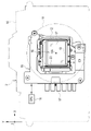
- FIG. 1 is a diagram showing a digital camera
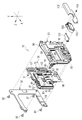
- FIG. 2 is a front exploded perspective view of the imaging device unit
- FIG. 4 is a rear exploded perspective view of the imaging element unit
- FIG. 4 is a rear exploded perspective view of the essential parts of the imaging element unit
- It is a perspective view of a 1st thermally-conductive member, a 2nd thermally-conductive member, and a 3rd thermally-conductive member.
- FIG. 1 is a diagram showing a digital camera
- FIG. 2 is a front exploded perspective view of the imaging device unit
- FIG. 4 is a rear exploded perspective view of the imaging element unit
- FIG. 4 is a rear exploded perspective view of the essential parts of the imaging element unit
- It is a perspective view of a 1st thermally-conductive member, a 2nd thermally-conductive member
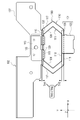
- FIG. 3 is a cross-sectional view of the main part of the imaging element unit; It is a perspective view of a 3rd thermally-conductive member, a 4th thermally-conductive member, and a connection member. It is a simple top view of a 1st thermally-conductive member. It is a figure which shows before bending of a 1st heat-conduction member, and after bending. It is a figure which shows a mode that a 1st thermally-conductive member deform
- FIG. 3 is a diagram showing a conduction path of driving heat of an image pickup device; FIG.
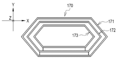
- FIG. 4 is a diagram showing a first thermally conductive member with a triple structure
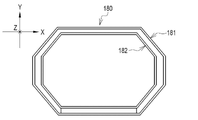
- FIG. 10 illustrates an octagonal first heat-conducting member
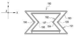
- FIG. 10 is a view showing the first heat conducting member in which the corners of the connection portion of the outer layer portion and the corners of the connection portion of the inner layer portion are recessed inward
- FIG. 10 is a diagram showing an imaging element unit having a fifth heat conducting member
- FIG. 10 is a diagram showing an imaging element unit having a fifth heat conducting member
- It is a simple top view of a 5th thermally-conductive member.
- the digital camera 2 has a camera body 10 .
- a lens mount 11 is provided on the front of the camera body 10 .
- a lens mount 11 has a circular imaging aperture 12 .
- An interchangeable imaging lens (not shown) is detachably attached to the lens mount 11 .
- the digital camera 2 is an example of an “imaging device” according to the technology of the present disclosure.
- the camera body 10 is an example of a “housing” according to the technology of the present disclosure.
- An imaging device unit 15 is built into the camera body 10 .
- a rectangular plate-shaped image sensor 16 is mounted on the image sensor unit 15 .
- the imaging element 16 is, for example, a CMOS (Complementary Metal Oxide Semiconductor) image sensor or a CCD (Charge Coupled Device) image sensor.
- the imaging device 16 has a rectangular imaging surface 17 for imaging a subject.
- the imaging surface 17 receives subject light that indicates the subject.
- pixels that photoelectrically convert received subject light and output electric signals are arranged two-dimensionally. The entire imaging surface 17 is exposed to the outside through the imaging aperture 12 .
- a CPU 18 is connected to the imaging element unit 15 .
- a CPU 18 controls the operation of the imaging device unit 15 .
- the CPU 18 is connected to a ROM (Read Only Memory) and/or a RAM (Random Access Memory) via a bus line.
- a computer is configured by these CPU 18, memory, and bus line.
- the imaging element unit 15 has a vibration isolation function.
- the anti-vibration function is a function for suppressing relative positional displacement between subject light incident on the imaging surface 17 and the digital camera 2 , which is caused by vibrations applied to the camera body 10 .
- Vibrations applied to the camera body 10 include camera shake of a user who shoots an object while holding the camera body 10 .
- the imaging element 16 is moved by the anti-vibration function in the direction to cancel the positional deviation by the amount that cancels out the positional deviation. More specifically, the anti-vibration function allows the X-axis direction parallel to the side 19 of the imaging surface 17 of the image sensor 16 and/or the side 20 perpendicular to the side 19, that is, to intersect the side 19 at an angle of 90°.
- the imaging element 16 is moved in the parallel Y-axis direction.
- the X-axis direction and the Y-axis direction are examples of the "plane direction" according to the technology of the present disclosure.
- the terms “perpendicular” and “90°” mean not only perfect orthogonality and 90°, but also substantially orthogonal and approximately 90° including errors allowed in design and manufacturing. also includes the meaning of Further, in this specification, the term “parallel” includes not only the meaning of perfect parallelism but also the meaning of substantially parallelism including an error allowed in terms of design and manufacturing.
- the side 19 is expressed as “lower”, and the side opposite to the side 19 in the Y-axis direction is expressed as "upper”.
- the side 20 is expressed as "left”, and the side opposite to side 20 in the X-axis direction is expressed as "right”.
- positional deviation refers to a phenomenon that occurs when the optical axis OA fluctuates with respect to the subject due to vibration.
- Optical axis OA refers to the optical axis of subject light incident on the imaging surface 17 through the imaging lens. Fluctuation of the optical axis OA means that the optical axis OA is tilted due to the positional deviation with respect to the reference axis (for example, the optical axis OA before the positional deviation occurs).
- canceling the positional deviation includes not only the elimination of the positional deviation but also the reduction of the positional deviation.
- the imaging device unit 15 includes a fixed member 30, a movable member 31, a yoke 32, and the like.
- the fixing member 30 is arranged on the rear side of the camera body 10
- the yoke 32 is arranged on the front side of the camera body 10 .
- the fixing member 30 is fixed to the camera body 10 .
- the fixed member 30 and the yoke 32 are fixed with a space therebetween in the Z-axis direction orthogonal to the X-axis and the Y-axis.
- the movable member 31 is arranged between the fixed member 30 and the yoke 32 via three balls 35, 36 and 37 of the same size.
- the movable member 31 can move in the X-axis direction and the Y-axis direction (rotate around the Z-axis) with respect to the fixed member 30 and the yoke 32 by the balls 35 to 37 .
- the Z axis is parallel to the optical axis OA before the positional deviation occurs.
- the fixing member 30 holds magnets 40 , 41 and 42 .
- Magnets 40 to 42 are attached to the front face of fixed member 30 facing movable member 31 .
- Each of the magnets 40 to 42 is a set of an elongated plate-shaped magnet with its N pole directed toward the movable member 31 and an elongated plate-shaped magnet with its S pole directed toward the movable member 31 side.
- the magnet 40 is arranged in the lower center of the fixing member 30 so that its long side extends along the X-axis direction.
- the magnets 41 and 42 are arranged along the Y-axis direction.
- the magnet 41 is arranged at the upper left corner of the fixed member 30 so that its long side extends along the Y-axis direction.
- the magnet 42 is arranged at the lower left corner of the fixed member 30 so that its long side extends along the Y-axis direction.
- a plate 45, a plate 46, and a plate 47 are attached to the front of the fixed member 30 in addition to the magnets 40-42.
- the plate 45 is arranged at the lower right corner of the fixing member 30 and above the magnet 40 .
- the plate 46 is arranged on the left side of the fixed member 30 and between the magnets 41 and 42 .
- the plate 47 is arranged at the upper right corner of the fixed member 30 .
- the plate 45 rotatably supports the ball 35
- the plate 46 rotatably supports the ball 36
- the plate 47 rotatably supports the ball 37 .
- the fixed member 30 is formed with square regulation openings 50 and 51 that regulate the movement range of the movable member 31 in the XY plane.
- the regulation opening 50 and the regulation opening 51 have substantially the same size when viewed from above in the Z-axis direction.
- a restriction opening 50 is formed between the magnet 42 and the plate 45 at the lower left corner of the fixed member 30 .
- the regulation opening 51 is formed to the left of the plate 47 at the upper right corner of the fixing member 30 . That is, the regulation opening 50 and the regulation opening 51 are arranged at substantially diagonal positions in the fixing member 30 .
- a female screw 55, a female screw 56, a female screw 57, and a female screw 58 are provided on the fixing member 30 via spacers.
- a female screw 55 is provided at the lower right corner of the fixing member 30 .
- a female thread 56 is provided at the upper left corner of the fixing member 30 .
- a female screw 57 is provided at the lower left corner of the fixing member 30 .
- a female screw 58 is provided at the upper right corner of the fixing member 30 .
- a relatively large rectangular access opening 59 is formed in the center of the fixing member 30 .
- the access opening 59 is provided for accessing the back surface of the movable member 31 from the back surface of the fixed member 30 .
- the movable member 31 holds the imaging element 16 and holds the coils 60 , 61 and 62 .
- the imaging element 16 is arranged in the central portion of the movable member 31 .
- the coil 60 is arranged at the center of the lower portion of the movable member 31 and at a position facing the magnet 40 in the Z-axis direction.
- the coil 61 is arranged at the upper left corner of the movable member 31 and at a position facing the magnet 41 in the Z-axis direction.
- the coil 62 is arranged at the lower left corner of the movable member 31 and at a position facing the magnet 42 in the Z-axis direction.
- the coil 60 is arranged such that its long side extends along the X-axis direction.
- the coils 61 and 62 are arranged along the Y-axis direction. Each of the coils 61 and 62 is arranged such that its long side extends along the Y-axis direction.
- a magnet 65 is held in the yoke 32 .
- a magnetic body 66 is attached to the coil 61 and a magnetic body 67 is attached to the coil 62 .
- Magnet 65 is, for example, a neodymium magnet.
- the magnetic bodies 66 and 67 are thin plate pieces made of iron, for example.
- a magnet 65 is arranged to cover the coil 60 and increases the driving force of the coil 60 .
- the magnetic bodies 66 and 67 are arranged along the Y-axis direction.
- the magnetic body 66 is arranged on the upper end side of the coil 61, and the magnetic body 67 is arranged on the lower end side of the coil 62, respectively.
- the magnet 65 Since the coil 60 is arranged at a position facing the magnet 40 in the Z-axis direction as described above, the magnet 65 is also arranged at a position facing the magnet 40 in the Z-axis direction. Therefore, the magnet 65 is attracted to the magnet 40 while being fixed to the yoke 32 .
- the magnetic body 66 is also arranged at a position facing the magnet 41 in the Z-axis direction. Therefore, the magnetic body 66 is attracted to the magnet 41 .
- the magnetic body 67 is also arranged at a position facing the magnet 42 in the Z-axis direction. Therefore, the magnetic body 67 is attracted to the magnet 42 .
- a concave portion 70 , a concave portion 71 , and a concave portion 72 are formed on the back surface of the movable member 31 facing the fixed member 30 .
- the concave portion 70 is arranged at the lower right corner of the movable member 31 and at a position facing the plate 45 in the Z-axis direction.
- the concave portion 71 is arranged between the coils 61 and 62 on the left side of the movable member 31 and at a position facing the plate 46 in the Z-axis direction.
- the concave portion 72 is arranged at the upper right corner of the movable member 31 and at a position facing the plate 47 in the Z-axis direction.
- the recess 70 rotatably accommodates the ball 35
- the recess 71 rotatably accommodates the ball 36
- the recess 72 rotatably accommodates the ball 37 .
- the size of the concave portions 70 to 72 when viewed from above in the Z-axis direction is slightly larger than the diameter of the balls 35 to 37 .
- the depth of the recesses 70-72 in the Z-axis direction is slightly smaller than the diameter of the balls 35-37.
- a cylindrical projection 80 projecting toward the fixed member 30 is provided on the rear surface of the movable member 31 at a position facing the regulation opening 50 in the Z-axis direction. Further, on the rear surface of the movable member 31, a cylindrical protrusion 81 protruding toward the fixed member 30 is provided at a position facing the regulation opening 51 in the Z-axis direction.
- the protrusion 80 is inserted through the regulation opening 50 . Also, the projection 81 is inserted through the regulation opening 51 . Therefore, the protrusions 80 and 81 work as restricting pins that restrict the movement of the movable member 31 in the XY plane.
- the yoke 32 is a magnetic material such as a thin iron plate, and has a substantially C shape. Yoke 32 forms a magnetic circuit with magnets 40-42 to increase the magnetic flux received by coils 60-62.
- a male screw 85 , a male screw 86 , a male screw 87 and a male screw 88 are attached to the yoke 32 .
- the male screws 85 - 88 are fastened and fixed to the female screws 55 - 58 of the fixing member 30 .
- the fixed member 30 and the yoke 32 are fixed, and the movable member 31 is movably held between the fixed member 30 and the yoke 32 .
- the imaging device unit 15 includes a pair of voice coil motors (VCM; Voice Coil Motor).
- VCM voice coil motors
- a pair of VCMs is a pair of a first VCM and a second VCM.
- the first VCM includes a pair of magnets 40 and coils 60 and a yoke 32, and generates power to move the movable member 31 in the Y-axis direction.
- the second VCM includes a pair of magnet 41 and coil 61, a pair of magnet 42 and coil 62, and yoke 32, and generates power to move movable member 31 in the X-axis direction.
- the first VCM generates power for moving the movable member 31 in the Y-axis direction by the magnetic force of the magnet 40 and the current flowing through the coil 60 .
- the second VCM also generates power for moving the movable member 31 in the X-axis direction by the magnetic force of the magnet 41 and the current flowing through the coil 61 and the magnetic force of the magnet 42 and the current flowing through the coil 62 .
- the movable member 31 is provided with a Hall element for detecting the position of the movable member 31, a temperature sensor for measuring the temperature around the Hall element, and the like.
- the CPU 18 finds the difference between the position of the movable member 31 detected by the Hall element and the target position of the movable member 31 for correcting the positional deviation, and performs feedback control to drive the VCM so as to eliminate the difference.
- the difference is large, the power generated by the VCM becomes relatively large, and conversely, when the difference is small, the power generated by the VCM becomes relatively small.
- the CPU 18 corrects the temperature drift of the Hall element using the temperature measured by the temperature sensor.
- a rectangular plate-shaped circuit board 90 having substantially the same size as the imaging element 16 is attached to the rear surface 89 of the imaging element 16 facing the imaging surface 17 .
- the circuit board 90 is made of resin such as epoxy, for example.
- a rectangular opening 91 is formed in the circuit board 90 .
- the opening 91 is formed in the center of the circuit board 90 and exposes the central region 92 of the back surface 89 of the imaging device 16 .
- the central region 92 is a region of a preset size that surrounds the center point C of the back surface 89 of the imaging device 16 .
- Identification information 98 of the imaging element 16 is written in the central area 92 .
- the opening 91 is formed for viewing this identification information 98 .
- the identification information 98 is, for example, a two-dimensional bar code for moving to an Internet page on which management numbers and management information are described.
- the central region 92 is an example of "a portion of the back surface" according to the technology of the present disclosure.
- the circuit board 90 is mounted with electric circuits such as a control circuit, a drive circuit, and a power supply circuit for the imaging device 16 .
- a connector 93 and a connector 94 are provided at the lower end of the back surface 89 of the circuit board 90 .
- a connector 95 is provided at the left end of the rear surface 89 of the circuit board 90 .
- One end of a flexible substrate 96 is connected to the connector 93 and the connector 94 .
- the other end of the flexible board 96 is pulled out to the back side of the fixing member 30 through the access opening 59 (see FIG. 7).
- the other end of the flexible substrate 96 is connected to the CPU 18, a power supply circuit (not shown) that supplies power from the battery, and the like.
- One end of a flexible substrate 97 (see FIG. 1) is connected to the connector 95 .
- the other end of the flexible substrate 97 wraps around the front of the movable member 31 and is connected to the imaging device 16 .
- the imaging device 16 is connected to the other end of the flexible substrate 97
- the connector 95 is connected to one end of the flexible substrate 97 .
- a flexible board 96 is connected to the connectors 93 and 94 , and the CPU 18 and the like are connected to the other end of the flexible board 96 . Therefore, the imaging device 16 , the circuit board 90 , the CPU 18 and the like are connected via a flexible board 97 , a connector 95 , a connector 93 and a connector 94 , and a flexible board 96 .
- the imaging element unit 15 further has a first thermally conductive member 100, a second thermally conductive member 101, and a third thermally conductive member 102 to which driving heat of the imaging element 16 is conducted.
- a second heat conduction member 101 and a third heat conduction member 102 are connected to the first heat conduction member 100 . Driving heat is conducted to the first heat conducting member 100 from the second heat conducting member 101 . In addition, the first heat conducting member 100 conducts driving heat to the third heat conducting member 102 .
- the second heat conducting member 101 is connected to the central region 92 of the rear surface 89 of the imaging element 16 exposed through the opening 91 . Driving heat is conducted from the central region 92 to the second heat conducting member 101 .
- the first thermally conductive member 100 and the second thermally conductive member 101 are fixed with an adhesive.
- a female screw 68 is formed in the fixing member 30 .
- An insertion hole 103 is formed in the first heat conducting member 100 .
- a male screw 104 is attached to the third heat conducting member 102 .
- the male screw 104 is passed through the insertion hole 103 of the first heat conducting member 100 and fastened to the female screw 68 of the fixing member 30 . Thereby, the first heat conducting member 100 and the third heat conducting member 102 are fixed.
- the first heat conducting member 100 is made of a graphite sheet.
- the graphite sheet has a configuration in which a graphite sheet main body is pouched with a resin film such as a PET (polyethylene terephthalate) film.
- the thickness of the graphite sheet body is, for example, 70 ⁇ m, and the thickness of the resin film is, for example, 5 ⁇ m.
- the second heat conducting member 101 and the third heat conducting member 102 are metal plates, such as copper plates. Therefore, the second heat conduction member 101 and the third heat conduction member 102 have higher rigidity than the first heat conduction member 100 made of a graphite sheet. In other words, the first heat-conducting member 100 has higher elasticity than the second heat-conducting member 101 and the third heat-conducting member 102 .
- the first heat conducting member 100 has a double structure having an outer layer portion 110 and an inner layer portion 111 .
- the inner layer portion 111 is connected to the outer layer portion 110 via a connection portion 112 (see also FIG. 9 and the like) and is arranged in a space surrounded by the outer layer portion 110 .
- a mounting portion 113 in which an insertion hole 103 is formed is provided on the upper portion of the outer layer portion 110 .
- Both the outer layer portion 110 and the inner layer portion 111 are hexagonal.
- the outer layer portion 110 includes a first sheet portion 115, a second sheet portion 116 having the same length as the first sheet portion 115 and facing the first sheet portion 115, and the first sheet portion 115 and the second sheet portion. 116 and a pair of V-shaped connecting portions 117 that connect the connecting portions 116 .
- the inner layer portion 111 includes a first sheet portion 118 , a second sheet portion 119 having the same length as the first sheet portion 118 and facing the first sheet portion 118 , and a first sheet portion 118 and a second sheet portion 119 . It is composed of a pair of V-shaped connecting portions 120 connecting two sheet portions 119 .
- the first sheet portion 115 and the second sheet portion 116, and the first sheet portion 118 and the second sheet portion 119 are planar.
- the second heat conducting member 101 has a first piece 125 and a second piece 126 .
- the first piece 125 is parallel to the imaging surface 17 and the rear surface 89 of the imaging device 16 and faces the rear surface 89 of the imaging device 16 .
- the first piece 125 is connected to the central region 92 of the back surface 89 .
- the second piece 126 is bent 90° from the first piece 125 and extends in the direction normal to the imaging surface 17 and the back surface 89 of the imaging device 16 .
- the normal direction of the imaging surface 17 and the back surface 89 of the imaging element 16 is the Z-axis direction (the direction of the optical axis OA before the positional deviation occurs).
- the second piece 126 has approximately the same size as the space between the first sheet portion 115 of the outer layer portion 110 and the first sheet portion 118 of the inner layer portion 111 .
- the second heat conducting member 101 is connected to the first heat conducting member 100 through the second piece 126 . More specifically, the second piece 126 is inserted into the space between the first sheet portion 115 of the outer layer portion 110 and the first sheet portion 118 of the inner layer portion 111 and sandwiched between the first sheet portions 115 and 118. is held in place. Double-sided tape is attached to the portions of the first sheet portion 115 and the first sheet portion 118 that are in contact with the second piece 126 . The adhesive of the double-sided tape fixes the first sheet portion 115, the first sheet portion 118 and the second piece 126, as well as the first heat conducting member 100 and the second heat conducting member 101 together.
- the third heat conducting member 102 has a first piece 127 and a second piece 128 .
- the first piece 127 is parallel to the imaging surface 17 and the back surface 89 of the imaging device 16 and has a wing shape elongated in the X-axis direction.
- the second piece 128 is bent 90° from the first piece 127 and extends in the direction normal to the imaging surface 17 and the back surface 89 of the imaging device 16 , similarly to the second piece 126 of the second thermally conductive member 101 .
- the third heat conducting member 102 is connected to the first heat conducting member 100 through the second piece 128 . More specifically, the second piece 128 is inserted into the space between the second sheet portion 116 of the outer layer portion 110 and the second sheet portion 119 of the inner layer portion 111 and sandwiched between the second sheet portions 116 and 119 . is held in place. The second piece 128 is provided with a claw 129 hooked on the edge of the second sheet portion 119 .
- the thickness TH2 of the second heat conduction member 101 is thicker than the thickness TH1 of the first heat conduction member 100.
- the thickness TH1 of the first thermally conductive member 100 is, for example, 80 ⁇ m, and the thickness of the second thermally conductive member 101 is, for example, 1 mm.
- the thickness of the third thermally conductive member 102 is also greater than the thickness TH1 of the first thermally conductive member 100, for example 1 mm.
- the flexible substrate 96 pulled out through the access opening 59 is arranged on the opposite side of the first heat conducting member 100 with the second piece 126 of the second heat conducting member 101 interposed therebetween. .
- a fourth heat conduction member 135 is attached to the third heat conduction member 102 with an adhesive.
- the fourth heat-conducting member 135 is made of a graphite sheet, like the first heat-conducting member 100 .
- the thickness TH4 of the fourth thermally conductive member 135 is thicker than the thickness TH1 of the first thermally conductive member 100 (see FIG. 6).
- a thickness TH4 of the fourth thermally conductive member 135 is, for example, 500 ⁇ m.
- a connecting member 136 is further attached to the fourth heat conducting member 135 with an adhesive.
- the connecting member 136 is a metal plate, such as a copper plate, like the second heat-conducting member 101 and the third heat-conducting member 102 .
- the connection member 136 is connected to the top plate 137 of the camera body 10 .
- the top plate 137 of the camera body 10 is, for example, a magnesium plate or an aluminum plate.
- the outer layer portion 110 of the first thermally conductive member 100 is hexagonal as described above, so that it has six corners 140, 141, 142, 143, 144, and 6 corners. 145.
- Inner layer portion 111 is also hexagonal and thus has six corners 146 , 147 , 148 , 149 , 150 and 151 .
- the corners 140 to 145 and the corners 146 to 151 function as bent portions that enable deformation following the movement of the imaging device 16 due to the anti-vibration function. Corners 140-145 flare outward. Similarly, corners 146-151 are also flared outward. That is, the first heat conducting member 100 has a shape like a pantograph.
- the first heat conducting member 100 is simplified by omitting the illustration of the mounting portion 113 . The same applies to FIGS. 11 and 12 and the like.
- the first thermally conductive member 100 is formed by folding a piece of sheet-like material 160 along the broken line. Specifically, first, the connection portion 112 is bent so that the portion that will become the outer layer portion 110 and the portion that will become the inner layer portion 111 face each other. Then, after the corners 146 to 151 are bent to form the inner layer portion 111, the corners 140 to 145 are bent to form the outer layer portion 110. FIG. Finally, the portion that will become the mounting portion 113 is bent to complete the first heat conducting member 100 .
- the first thermally conductive member 100 has a reinforcing layer 161 .
- the reinforcing layer 161 is a resin film such as a 40 ⁇ m thick PET film.
- the reinforcing layer 161 is provided on the two sides forming the connecting portion 117 and the connecting portion 120, and is not provided on the corners 144, 145, 150, and 151 that function as bent portions.
- the two sides forming the connecting portion 117 and the connecting portion 120 are thicker than the corners 144, 145, 150, and 151 functioning as bent portions due to the reinforcement layer 161.
- the first thermally conductive member 100 deforms so as to follow the movement of the imaging device 16 due to the anti-vibration function.
- FIG. 11 shows how the first thermal conductive member 100 expands and contracts in the vertical direction and deforms following the movement of the imaging device 16 along the Y-axis direction due to the anti-vibration function.
- FIG. 12 shows how the first heat conducting member 100 tilts and deforms in the left-right direction following the movement of the imaging element 16 along the X-axis direction due to the anti-vibration function.
- the drive heat of the imaging element 16 follows the conduction path shown in FIG. That is, the drive heat of the imaging element 16 is first conducted from the rear surface 89 of the imaging element 16 to the second heat conducting member 101 connected to the central region 92 of the rear surface 89 . The driving heat is then conducted from the second heat-conducting member 101 to the first heat-conducting member 100 connected through the second piece 126 of the second heat-conducting member 101 .
- the driving heat conducted to the first heat conducting member 100 is conducted to the third heat conducting member 102 connected through the second piece 128 . Furthermore, the driving heat is conducted from the third heat conducting member 102 to the fourth heat conducting member 135 and from the fourth heat conducting member 135 to the connecting member 136 . Then, the heat is conducted to the top plate 137 of the camera body 10 through the connection member 136 and radiated to the outside through the top plate 137 .
- the imaging element unit 15 is made such that the movable member 31 is movable with respect to the fixed member 30 and the yoke 32 .
- the movable member 31 holds the imaging device 16 . Therefore, the imaging element 16 also moves along with the movement of the movable member 31 .
- the movable member 31 and, in turn, the imaging element 16 are moved under the control of the CPU 18 in the direction of canceling the positional displacement by the amount to cancel the positional displacement. be moved.
- the first thermally conductive member 100 is deformed following the movement of the imaging device 16 due to this anti-vibration function.
- the imaging device unit 15 includes the imaging device 16 having the imaging surface 17 for imaging a subject and the back surface 89 facing the imaging surface 17 , the circuit board 90 attached to the back surface 89 , and the imaging device 16 . It comprises a first heat conducting member 100 and a second heat conducting member 101 to which driving heat is conducted.
- the circuit board 90 is formed with an opening 91 that exposes a central region 92 of the back surface 89 of the imaging device 16 .
- the first heat-conducting member 100 is connected to the second heat-conducting member 101 and has higher elasticity than the second heat-conducting member 101 .
- a second thermally conductive member 101 is connected to the rear surface 89 through the opening 91 .
- the second thermally conductive member 101 which has a relatively high rigidity and is difficult to deform, is directly connected to the imaging device 16, compared to the case where the first thermally conductive member 100, which has a relatively high elasticity and is easily deformed, is directly connected to the imaging device 16, It is possible to make it difficult for the thermally conductive member to peel off from the imaging element 16 .
- the imaging device unit 15 has a vibration isolation function that moves the imaging device 16 in the planar direction. As shown in FIGS. 11 and 12, the first thermally conductive member 100 deforms so as to follow the movement of the imaging device 16 due to the anti-vibration function. Therefore, by directly connecting the second heat-conducting member 101, which has relatively high rigidity and is difficult to deform, to the imaging device 16, the effect that the heat-conducting member is difficult to peel off can be further exhibited.
- the first thermally conductive member 100 when the first thermally conductive member 100 is directly connected to the imaging element 16, it is necessary to increase the thickness TH1 of the first thermally conductive member 100 in order to increase the conduction efficiency. If the thickness TH1 is thicker, the repulsive force of the first heat conducting member 100 is increased accordingly, and the deformation following the movement of the imaging device 16 due to the anti-vibration function becomes difficult. However, in this example, it is not necessary to increase the thickness TH1 of the first heat conducting member 100 so much. Therefore, the first thermally conductive member 100 can follow the movement of the imaging element 16 due to the anti-vibration function and deform without much resistance, as compared with the case where the first thermally conductive member 100 is directly connected to the imaging element 16 .
- the second heat conducting member 101 is connected to the central region 92 and has a first piece 125 facing the back surface 89 and a second piece 126 bent from the first piece 125. .
- the first heat conducting member 100 is connected to the second piece 126 . Therefore, the first thermally conductive member 100 deforms so as to follow the movement of the second piece 126 rather than the movement of the imaging element 16 itself. When deformed so as to follow the movement of the imaging element 16 itself, the first heat conduction member 100 needs to have a complicated structure. 100 can be of simple construction.
- the second piece 126 extends in the normal direction of the imaging surface 17 and the back surface 89 . Therefore, the first heat conducting member 100 can have a simpler configuration.
- the angle at which the second piece 126 is bent from the first piece 125 may be less than 90° or greater than 90°.
- the imaging device unit 15 includes a flexible board 96 attached to the circuit board 90 . As shown in FIG. 7, the flexible board 96 is arranged on the side opposite to the first heat conducting member 100 with the second piece 126 of the second heat conducting member 101 interposed therebetween. Therefore, there is no possibility that the flexible substrate 96 and the first thermally conductive member 100 will come into contact with each other and the signals to and/or from the imaging element 16 will be disturbed.
- the thickness TH2 of the second heat conduction member 101 is thicker than the thickness TH1 of the first heat conduction member 100. Therefore, the heat conduction efficiency of the second heat conduction member 101 can be enhanced.
- the thermal conductivity of the graphite sheet forming the first thermally conductive member 100 is 1600 w/m ⁇ K.
- the thermal conductivity of copper forming the second thermally conductive member 101 is 390 W/m ⁇ K, which is lower than that of the graphite sheet.
- the thickness TH2 of the second thermally conductive member 101 is larger than the thickness TH1 of the first thermally conductive member 100 as described above, the low thermal conductivity can be compensated for. Thereby, the heat conduction efficiency of the second heat conduction member 101 can be made higher than that of the first heat conduction member 100 . If the thermal conductivity of the second heat conducting member 101 is higher than that of the first heat conducting member 100 , the driving heat can be smoothly conducted from the second heat conducting member 101 to the first heat conducting member 100 .
- the thermal conductivity of the second thermally conductive member 101 is made higher than that of the first thermally conductive member 100, but the present invention is not limited to this. Instead of increasing the thickness TH2 of the second heat conduction member 101, or in addition, by forming the second heat conduction member 101 with a material having a higher thermal conductivity than the first heat conduction member 100, the The thermal conductivity of the second thermally conductive member 101 may be higher than that of the first thermally conductive member 100 .
- the opening 91 of the circuit board 90 exposes the central region 92 of the back surface 89 of the imaging device 16 .
- a center region 92 is a portion of the rear surface 89 of the imaging device 16 where the driving heat of the imaging device 16 is the highest. For this reason, the drive heat of the imaging device 16 can be more effectively radiated.
- the central area 92 is an area in which the identification information 98 of the imaging device 16 is described. Therefore, the opening 91 formed for visually recognizing the identification information 98 can be effectively used to radiate driving heat of the imaging device 16 .
- the first thermally conductive member 100 is made of a graphite sheet, and the second thermally conductive member 101 and the third thermally conductive member 102 are made of metal. Therefore, the first heat conducting member 100 can be given appropriate elasticity, and the second heat conducting member 101 and the third heat conducting member 102 can be given appropriate rigidity.
- the first heat conducting member 100 has an outer layer portion 110 and an inner layer portion 111 connected to the outer layer portion 110 and arranged in a space surrounded by the outer layer portion 110 .
- Each of the outer layer portion 110 and the inner layer portion 111 has bent portions (corners 140 to 145 and corners 146 to 151) that enable deformation following the movement of the imaging device 16 due to the anti-vibration function. Therefore, compared to the case where only the outer layer portion 110 is provided, it is possible to dissipate the driving heat of the imaging element 16 more efficiently. As a result, shooting such as 4K/120p moving image shooting that imposes a relatively large load on the image sensor 16 can be performed for a longer time than before.
- the installation space for the thermally conductive member can be saved.
- the first thermally conductive member 100 is formed by folding one sheet-like material 160 . Therefore, the first thermally conductive member 100 can be formed more easily than when the outer layer portion 110 and the inner layer portion 111 are formed from different materials and then connected.
- the first heat conducting member 100 includes a first sheet portion 115 and a first sheet portion 118, a second sheet portion 116 facing the first sheet portion 115 and the first sheet portion 118, and a It is composed of a second sheet portion 119 , a connecting portion 117 connecting the first sheet portions 115 and 118 , and a connecting portion 120 connecting the second sheet portions 116 and 119 .
- the first thermally conductive member 100 can be deformed naturally by following the movement of the imaging device 16 due to the anti-vibration function.
- the outer layer portion 110 and the inner layer portion 111 have corners 140 to 145 and corners 146 to 151 that function as bent portions projecting outward. Therefore, a large space surrounded by the outer layer portion 110 can be secured, and the inner layer portion 111 can be easily formed.
- the first thermally conductive member 100 is a portion other than the corners 144, 145, 150, and 151 functioning as bent portions, and constitutes the connection portion 117 and the connection portion 120. It has reinforcing layers 161 on two sides.
- the two sides forming the connecting portion 117 and the connecting portion 120 are thicker than the corners 140 to 145 and the corners 146 to 151 functioning as bent portions due to the reinforcing layer 161 . Therefore, unintended deformation of the two sides forming connection portion 117 and connection portion 120 can be prevented.
- the reinforcing layer 161 is not provided at the corners 140 to 145 and the corners 146 to 151 that function as bent portions, the first heat conducting member 100 follows the movement of the imaging element 16 by the anti-vibration function, resulting in large resistance. can be transformed without
- the reinforcing layer 161 may be provided on the first sheet portion 115 and the first sheet portion 118 and the second sheet portion 116 and the second sheet portion 119 .
- the first thermally conductive member 100 is connected to the imaging element 16 via the second thermally conductive member 101 and is connected to the camera body 10 via the third thermally conductive member 102 .
- the second thermally conductive member 101 and the third thermally conductive member 102 are sandwiched between the outer layer portion 110 and the inner layer portion 111 . Therefore, the driving heat conduction efficiency from the second heat conduction member 101 to the first heat conduction member 100 and the driving heat conduction efficiency from the first heat conduction member 100 to the third heat conduction member 102 can be improved. can.
- the holding force of the second heat conduction member 101 and the third heat conduction member 102 by the first heat conduction member 100 can be increased.
- the third heat conducting member 102 may constitute a part of the camera body 10 .
- a fourth heat conduction member 135 made of a graphite sheet is connected between the third heat conduction member 102 and the top plate 137 of the camera body 10.
- the thickness TH4 of the fourth thermally conductive member 135 is thicker than the thickness TH1 of the first thermally conductive member 100 .
- the fourth heat conduction member 135 does not deform so as to follow the movement of the imaging element 16 due to the anti-vibration function. Therefore, unlike the first heat conducting member 100, it is not necessary to make the thickness TH1 comparatively thin in order to realize smooth deformation at the expense of the conduction efficiency of driving heat. high conduction efficiency.
- the number of inner layer parts 111 is not limited to one.
- a triple structure having one outer layer portion 171 and two inner layer portions 172 and 173 arranged in a space surrounded by the outer layer portion 171 may be employed.
- the shape of the first heat conducting member is not limited to a hexagon.
- the outer layer portion 181 and the inner layer portion 182 may be octagonal. Further, as shown in FIG.
- a first heat conducting member 190 in which corners 195 and 196 of a connecting portion 193 of an outer layer portion 191 and corners 197 and 198 of a connecting portion 194 of an inner layer portion 192 are recessed inward.
- the first heat-conducting member 190 has a shape that is, so to speak, a combination of " ⁇ " and its mirror image.
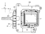
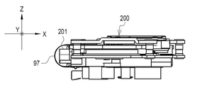
- an imaging device unit 200 of the second embodiment has a fifth thermally conductive member 201.
- the fifth heat-conducting member 201 is a flexible substrate 97 connected to the imaging element 16 and wrapped around the front surface of the movable member 31 at a position facing the side surface 202 of the imaging element 16 that connects the imaging surface 17 and the back surface 89 . It is arranged in the space to be formed.
- Driving heat of the imaging element 16 is conducted to the fifth heat conducting member 201 from the side surface 202 .
- a sixth heat conduction member 203 made of a metal plate is connected to the fifth heat conduction member 201 .
- the sixth heat conducting member 203 is connected to the side plate of the camera body 10 or the like.
- Driving heat from the fifth heat-conducting member 201 is conducted to the camera body 10 through the sixth heat-conducting member 203 .
- the fifth heat-conducting member 201 is made of a graphite sheet like the first heat-conducting member 100 and has high elasticity. Like the first heat conduction member 100 and the like, the fifth heat conduction member 201 deforms so as to be able to follow the movement of the imaging device 16 due to the anti-vibration function. However, unlike the first heat conducting member 100 and the like, the fifth heat conducting member 201 has no inner layer portion.
- the fifth heat conduction member 201 is a hexagon having six corners 205 , 206 , 207 , 208 , 209 , and 210 like the first heat conduction member 100 . It is rectangular. The corners 205 to 210 function as bent portions that enable deformation following the movement of the imaging device 16 due to the anti-vibration function.
- the fifth heat conduction member 201 has a first sheet portion 211 and a second sheet portion 211 having the same length as the first sheet portion 211 and facing the first sheet portion 211 , similarly to the first heat conduction member 100 .
- Angle ⁇ 5 of corners 209 and 210 functioning as bent portions of connecting portion 213 is equal to angles 144 and 145 functioning as bent portions of connecting portion 117 and connecting portion 120 of first heat conducting member 100, and angle 150 and angle It is sharper than the angle ⁇ 1 of 151 (see FIG. 9).
- the imaging device unit 200 of the second embodiment includes the fifth thermally conductive member 201.
- the fifth heat-conducting member 201 is arranged at a position facing a side surface 202 of the imaging element 16 that connects the imaging surface 17 and the back surface 89 .
- Driving heat is conducted to the fifth heat conducting member 201 from the side surface 202 .
- the fifth thermally conductive member 201 deforms so as to follow the movement of the imaging device 16 due to the anti-vibration function.
- the fifth heat-conducting member 201 has a bent portion that enables deformation following the movement of the imaging device 16 due to the anti-vibration function. Therefore, the drive heat can be more effectively radiated without hindering the movement of the imaging device 16 by the anti-vibration function.
- the fifth heat conducting member 201 is composed of a first sheet portion 211, a second sheet portion 212 facing the first sheet portion 211, and a connecting portion 213 connecting the first sheet portion 211 and the second sheet portion 212. be. For this reason, the fifth heat conducting member 201 can be deformed without difficulty by following the movement of the imaging element 16 due to the anti-vibration function, while securing the connecting portion with the sixth heat conducting member 203 and the like.
- the angle ⁇ 5 formed by the bent portion of the connecting portion 213 of the fifth heat conducting member is sharper than the angle ⁇ 1 formed between the connecting portion 117 of the first heat conducting member 100 and the bent portion of the connecting portion 120 . Therefore, the repulsive force of the fifth thermally conductive member 201 can be reduced, and the fifth thermally conductive member 201 can follow the movement of the imaging element 16 due to the anti-vibration function, and can be deformed without much resistance.
- the fifth heat conduction member 201 becomes more compact than the first heat conduction member 100 because the distance between the first sheet portion 211 and the second sheet portion 212 is reduced. Therefore, it can be arranged in a relatively narrow space such as a space formed by the flexible substrate 97 at a position facing the side surface 202 of the image sensor 16 .
- the fifth heat conducting member 201 is made of a graphite sheet. Therefore, the fifth heat conducting member 201 can be given appropriate elasticity.
- the fifth heat conducting member 201 may have a multi-layer structure. Further, as in the example shown in FIG. 15, the fifth heat conducting member 201 may be octagonal. Furthermore, as in the example shown in FIG. 16, the fifth heat conducting member 201 may have a structure in which the corners of the connecting portion are recessed inward.
- the CPU 18 has been exemplified as a processor that controls the operation of the imaging element unit 15, it is not limited to this.
- a programmable logic device which is a processor whose circuit configuration can be changed after manufacture, such as an FPGA (Field Programmable Gate Array), and/or an ASIC (Application Specific Integrated Circuit)
- FPGA Field Programmable Gate Array
- ASIC Application Specific Integrated Circuit
- the plates 45 to 47 are provided on the fixed member 30 and the recesses 70 to 72 are provided on the movable member 31, but this is not the only option.
- the plates 45-47 may be provided on the movable member 31, and the recesses 70-72 may be provided on the fixed member 30, respectively.
- the magnets 40 to 42 are provided on the fixed member 30 and the coils 60 to 62 are provided on the movable member 31, respectively, but the present invention is not limited to this.
- the magnets 40-42 may be provided on the movable member 31, and the coils 60-62 may be provided on the fixed member 30, respectively.
- the number of sets of balls 35-37, plates 45-47, and recesses 70-72 is not limited to three, and may be four or more.
- the imaging device unit of the present disclosure can also be applied to imaging devices other than the illustrated digital camera 2, such as smartphones, tablet terminals, or surveillance cameras.
- a and/or B is synonymous with “at least one of A and B.” That is, “A and/or B” means that only A, only B, or a combination of A and B may be used.
- a and/or B means that only A, only B, or a combination of A and B may be used.
Landscapes
- Engineering & Computer Science (AREA)
- Multimedia (AREA)
- Signal Processing (AREA)
- Physics & Mathematics (AREA)
- Electromagnetism (AREA)
- Studio Devices (AREA)
Priority Applications (3)
| Application Number | Priority Date | Filing Date | Title |
|---|---|---|---|
| JP2023502081A JPWO2022180976A1 (https=) | 2021-02-24 | 2021-12-01 | |
| CN202180094011.9A CN116982319A (zh) | 2021-02-24 | 2021-12-01 | 成像元件单元及摄像装置 |
| US18/451,121 US12457395B2 (en) | 2021-02-24 | 2023-08-17 | Imaging element unit and imaging device |
Applications Claiming Priority (2)
| Application Number | Priority Date | Filing Date | Title |
|---|---|---|---|
| JP2021-027337 | 2021-02-24 | ||
| JP2021027337 | 2021-02-24 |
Related Child Applications (1)
| Application Number | Title | Priority Date | Filing Date |
|---|---|---|---|
| US18/451,121 Continuation US12457395B2 (en) | 2021-02-24 | 2023-08-17 | Imaging element unit and imaging device |
Publications (1)
| Publication Number | Publication Date |
|---|---|
| WO2022180976A1 true WO2022180976A1 (ja) | 2022-09-01 |
Family
ID=83047960
Family Applications (1)
| Application Number | Title | Priority Date | Filing Date |
|---|---|---|---|
| PCT/JP2021/044148 Ceased WO2022180976A1 (ja) | 2021-02-24 | 2021-12-01 | 撮像素子ユニット、および撮像装置 |
Country Status (4)
| Country | Link |
|---|---|
| US (1) | US12457395B2 (https=) |
| JP (1) | JPWO2022180976A1 (https=) |
| CN (1) | CN116982319A (https=) |
| WO (1) | WO2022180976A1 (https=) |
Families Citing this family (3)
| Publication number | Priority date | Publication date | Assignee | Title |
|---|---|---|---|---|
| JP2023154620A (ja) * | 2022-04-07 | 2023-10-20 | キヤノン株式会社 | 撮像装置 |
| JP7840781B2 (ja) * | 2022-04-28 | 2026-04-06 | キヤノン株式会社 | 撮像装置 |
| JP2025069807A (ja) * | 2023-10-18 | 2025-05-01 | パナソニックIpマネジメント株式会社 | 撮像装置 |
Citations (2)
| Publication number | Priority date | Publication date | Assignee | Title |
|---|---|---|---|---|
| JP2020067632A (ja) * | 2018-10-26 | 2020-04-30 | パナソニックIpマネジメント株式会社 | 撮像装置 |
| WO2020202811A1 (ja) * | 2019-03-29 | 2020-10-08 | ソニー株式会社 | 像ぶれ補正装置及び撮像装置 |
Family Cites Families (4)
| Publication number | Priority date | Publication date | Assignee | Title |
|---|---|---|---|---|
| JP5168047B2 (ja) | 2008-09-22 | 2013-03-21 | カシオ計算機株式会社 | カメラ |
| US10613420B2 (en) * | 2016-08-05 | 2020-04-07 | Gopro, Inc. | Heat spreader for camera |
| JP6949686B2 (ja) * | 2017-11-29 | 2021-10-13 | Omデジタルソリューションズ株式会社 | 撮像装置 |
| JP7802499B2 (ja) * | 2021-11-24 | 2026-01-20 | キヤノン株式会社 | 撮像装置 |
-
2021
- 2021-12-01 WO PCT/JP2021/044148 patent/WO2022180976A1/ja not_active Ceased
- 2021-12-01 CN CN202180094011.9A patent/CN116982319A/zh active Pending
- 2021-12-01 JP JP2023502081A patent/JPWO2022180976A1/ja active Pending
-
2023
- 2023-08-17 US US18/451,121 patent/US12457395B2/en active Active
Patent Citations (2)
| Publication number | Priority date | Publication date | Assignee | Title |
|---|---|---|---|---|
| JP2020067632A (ja) * | 2018-10-26 | 2020-04-30 | パナソニックIpマネジメント株式会社 | 撮像装置 |
| WO2020202811A1 (ja) * | 2019-03-29 | 2020-10-08 | ソニー株式会社 | 像ぶれ補正装置及び撮像装置 |
Also Published As
| Publication number | Publication date |
|---|---|
| CN116982319A (zh) | 2023-10-31 |
| JPWO2022180976A1 (https=) | 2022-09-01 |
| US12457395B2 (en) | 2025-10-28 |
| US20230396863A1 (en) | 2023-12-07 |
Similar Documents
| Publication | Publication Date | Title |
|---|---|---|
| US20230056716A1 (en) | Lens driving apparatus and camera module including the same | |
| JP6876568B2 (ja) | レンズ駆動装置 | |
| WO2022180976A1 (ja) | 撮像素子ユニット、および撮像装置 | |
| JP6960983B2 (ja) | 手振れ補正機能付き撮像装置 | |
| JP5740567B2 (ja) | 撮像ユニットの放熱構造 | |
| CN216817067U (zh) | 光学元件驱动机构 | |
| CN215340478U (zh) | 光学系统 | |
| CN115236915B (zh) | 一种摄像装置以及便携式电子设备 | |
| JP5995106B2 (ja) | 撮像ユニット | |
| WO2013046816A1 (ja) | 像振れ補正装置及びそれを備えた撮像装置 | |
| JP7216853B1 (ja) | 撮像装置及び携帯型電子機器 | |
| CN117741996A (zh) | 光学元件驱动机构 | |
| JP2025114732A (ja) | 撮像素子ユニット、および撮像装置 | |
| JP7371131B2 (ja) | 防振装置、および撮像装置 | |
| JP6316000B2 (ja) | 撮像素子ユニット、及び光学機器 | |
| US12348867B2 (en) | Imaging device | |
| JP2020067632A (ja) | 撮像装置 | |
| JP2013073201A (ja) | 像振れ補正装置及びそれを備えた撮像装置 | |
| JP2011085675A (ja) | 光学素子駆動装置及び撮像装置 | |
| US20250193501A1 (en) | Imaging element unit and imaging apparatus | |
| US20250184586A1 (en) | Imaging element unit and imaging apparatus | |
| JP5788280B2 (ja) | 像振れ補正装置及びそれを備えた撮像装置 | |
| JP2007148023A (ja) | 像ぶれ補正装置及びそれを用いた撮像装置 | |
| TWM470962U (zh) | 鏡頭防震裝置 | |
| JP2015075658A (ja) | 光学機器 |
Legal Events
| Date | Code | Title | Description |
|---|---|---|---|
| 121 | Ep: the epo has been informed by wipo that ep was designated in this application |
Ref document number: 21928069 Country of ref document: EP Kind code of ref document: A1 |
|
| WWE | Wipo information: entry into national phase |
Ref document number: 2023502081 Country of ref document: JP |
|
| WWE | Wipo information: entry into national phase |
Ref document number: 202180094011.9 Country of ref document: CN |
|
| NENP | Non-entry into the national phase |
Ref country code: DE |
|
| 122 | Ep: pct application non-entry in european phase |
Ref document number: 21928069 Country of ref document: EP Kind code of ref document: A1 |