WO2022180944A1 - テープ貼付装置及びテープマガジン - Google Patents
テープ貼付装置及びテープマガジン Download PDFInfo
- Publication number
- WO2022180944A1 WO2022180944A1 PCT/JP2021/041649 JP2021041649W WO2022180944A1 WO 2022180944 A1 WO2022180944 A1 WO 2022180944A1 JP 2021041649 W JP2021041649 W JP 2021041649W WO 2022180944 A1 WO2022180944 A1 WO 2022180944A1
- Authority
- WO
- WIPO (PCT)
- Prior art keywords
- tape
- dicing
- magazine
- dicing tape
- base
- Prior art date
- Legal status (The legal status is an assumption and is not a legal conclusion. Google has not performed a legal analysis and makes no representation as to the accuracy of the status listed.)
- Ceased
Links
Images



Classifications
-
- H—ELECTRICITY
- H10—SEMICONDUCTOR DEVICES; ELECTRIC SOLID-STATE DEVICES NOT OTHERWISE PROVIDED FOR
- H10P—GENERIC PROCESSES OR APPARATUS FOR THE MANUFACTURE OR TREATMENT OF DEVICES COVERED BY CLASS H10
- H10P72/00—Handling or holding of wafers, substrates or devices during manufacture or treatment thereof
- H10P72/04—Apparatus for manufacture or treatment
- H10P72/0442—Apparatus for placing on an insulating substrate, e.g. tape
-
- B—PERFORMING OPERATIONS; TRANSPORTING
- B65—CONVEYING; PACKING; STORING; HANDLING THIN OR FILAMENTARY MATERIAL
- B65H—HANDLING THIN OR FILAMENTARY MATERIAL, e.g. SHEETS, WEBS, CABLES
- B65H19/00—Changing the web roll
- B65H19/10—Changing the web roll in unwinding mechanisms or in connection with unwinding operations
- B65H19/12—Lifting, transporting, or inserting the web roll; Removing empty core
- B65H19/123—Lifting, transporting, or inserting the web roll; Removing empty core with cantilever supporting arrangements
-
- B—PERFORMING OPERATIONS; TRANSPORTING
- B65—CONVEYING; PACKING; STORING; HANDLING THIN OR FILAMENTARY MATERIAL
- B65H—HANDLING THIN OR FILAMENTARY MATERIAL, e.g. SHEETS, WEBS, CABLES
- B65H35/00—Delivering articles from cutting or line-perforating machines; Article or web delivery apparatus incorporating cutting or line-perforating devices, e.g. adhesive tape dispensers
- B65H35/0006—Article or web delivery apparatus incorporating cutting or line-perforating devices
- B65H35/0013—Article or web delivery apparatus incorporating cutting or line-perforating devices and applying the article or the web by adhesive to a surface
-
- B—PERFORMING OPERATIONS; TRANSPORTING
- B65—CONVEYING; PACKING; STORING; HANDLING THIN OR FILAMENTARY MATERIAL
- B65H—HANDLING THIN OR FILAMENTARY MATERIAL, e.g. SHEETS, WEBS, CABLES
- B65H35/00—Delivering articles from cutting or line-perforating machines; Article or web delivery apparatus incorporating cutting or line-perforating devices, e.g. adhesive tape dispensers
- B65H35/0006—Article or web delivery apparatus incorporating cutting or line-perforating devices
- B65H35/002—Hand-held or table apparatus
- B65H35/0026—Hand-held or table apparatus for delivering pressure-sensitive adhesive tape
- B65H35/0033—Hand-held or table apparatus for delivering pressure-sensitive adhesive tape and affixing it to a surface
-
- H—ELECTRICITY
- H10—SEMICONDUCTOR DEVICES; ELECTRIC SOLID-STATE DEVICES NOT OTHERWISE PROVIDED FOR
- H10P—GENERIC PROCESSES OR APPARATUS FOR THE MANUFACTURE OR TREATMENT OF DEVICES COVERED BY CLASS H10
- H10P72/00—Handling or holding of wafers, substrates or devices during manufacture or treatment thereof
- H10P72/70—Handling or holding of wafers, substrates or devices during manufacture or treatment thereof for supporting or gripping
- H10P72/74—Handling or holding of wafers, substrates or devices during manufacture or treatment thereof for supporting or gripping using temporarily an auxiliary support
- H10P72/7402—Wafer tapes, e.g. grinding or dicing support tapes
-
- H—ELECTRICITY
- H10—SEMICONDUCTOR DEVICES; ELECTRIC SOLID-STATE DEVICES NOT OTHERWISE PROVIDED FOR
- H10P—GENERIC PROCESSES OR APPARATUS FOR THE MANUFACTURE OR TREATMENT OF DEVICES COVERED BY CLASS H10
- H10P72/00—Handling or holding of wafers, substrates or devices during manufacture or treatment thereof
- H10P72/70—Handling or holding of wafers, substrates or devices during manufacture or treatment thereof for supporting or gripping
- H10P72/74—Handling or holding of wafers, substrates or devices during manufacture or treatment thereof for supporting or gripping using temporarily an auxiliary support
- H10P72/7416—Handling or holding of wafers, substrates or devices during manufacture or treatment thereof for supporting or gripping using temporarily an auxiliary support used during dicing or grinding
-
- H—ELECTRICITY
- H10—SEMICONDUCTOR DEVICES; ELECTRIC SOLID-STATE DEVICES NOT OTHERWISE PROVIDED FOR
- H10P—GENERIC PROCESSES OR APPARATUS FOR THE MANUFACTURE OR TREATMENT OF DEVICES COVERED BY CLASS H10
- H10P95/00—Generic processes or apparatus for manufacture or treatments not covered by the other groups of this subclass
-
- B—PERFORMING OPERATIONS; TRANSPORTING
- B65—CONVEYING; PACKING; STORING; HANDLING THIN OR FILAMENTARY MATERIAL
- B65H—HANDLING THIN OR FILAMENTARY MATERIAL, e.g. SHEETS, WEBS, CABLES
- B65H2404/00—Parts for transporting or guiding the handled material
- B65H2404/10—Rollers
- B65H2404/14—Roller pairs
- B65H2404/142—Roller pairs arranged on movable frame
- B65H2404/1422—Roller pairs arranged on movable frame reciprocating
-
- B—PERFORMING OPERATIONS; TRANSPORTING
- B65—CONVEYING; PACKING; STORING; HANDLING THIN OR FILAMENTARY MATERIAL
- B65H—HANDLING THIN OR FILAMENTARY MATERIAL, e.g. SHEETS, WEBS, CABLES
- B65H2404/00—Parts for transporting or guiding the handled material
- B65H2404/10—Rollers
- B65H2404/14—Roller pairs
- B65H2404/147—Roller pairs both nip rollers being driven
-
- B—PERFORMING OPERATIONS; TRANSPORTING
- B65—CONVEYING; PACKING; STORING; HANDLING THIN OR FILAMENTARY MATERIAL
- B65H—HANDLING THIN OR FILAMENTARY MATERIAL, e.g. SHEETS, WEBS, CABLES
- B65H2701/00—Handled material; Storage means
- B65H2701/30—Handled filamentary material
- B65H2701/37—Tapes
Definitions
- the present invention relates to a tape applying device for a dicing tape and a tape magazine used for this tape applying device.
- Patent Literature 1 describes that an expanding tape E is attached to a wafer W adsorbed and fixed to a table 211 by pressure of an attaching roller.
- symbol is a thing of patent document 1.
- the present invention provides a tape applying apparatus for applying a dicing tape to a dicing frame and a work, wherein a part of the dicing tape wound in a roll is pulled out.
- the tape magazine in which the dicing tape is partially pulled out is replaced with the tape sticking device, and the regulating section regulates the dicing tape pull-out area to a predetermined trajectory, Switching and replacement of the dicing tape can be performed automatically.
- a tape magazine is a tape magazine that can be replaced with a tape sticking device that sticks a dicing tape to a dicing frame and a work, the base being replaceable with the tape sticking device, A feeding shaft provided on the base for supporting the dicing tape wound in a roll shape, and a winding shaft provided on the base for winding a separator of the dicing tape, wherein the dicing tape is A part of the dicing tape is supported by the feed shaft and the take-up shaft in a drawn-out state, and the drawn-out region from which the dicing tape is partially drawn out can be regulated along a predetermined trajectory by the regulating portion of the tape applying device.
- the tape magazine in which the dicing tape is partially pulled out is replaced with the tape sticking device, and the regulating section regulates the dicing tape pull-out area to a predetermined trajectory, Switching and replacement of the dicing tape can be performed automatically.
- the present invention can automatically switch and replace the dicing tape.
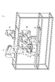
- FIG. 1 is a perspective view showing the configuration of a tape sticking system to which a tape sticking device according to one embodiment of the present invention is applied;
- FIG. FIG. 1 is a schematic diagram showing the configuration of a tape sticking system;
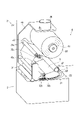
- FIG. 1 is a perspective view showing the configuration of a tape sticking device;
- FIG. 2 is a perspective view showing the configuration of a tape magazine;
- FIG. 2 is a block diagram showing the main configuration of the tape sticking system;
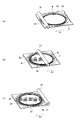
- FIG. 4 is a schematic diagram showing a procedure for automatically setting a dicing tape;
- FIG. 4 is a schematic diagram showing a procedure for attaching a dicing tape to a workpiece and a dicing frame;
- drawings may exaggerate by enlarging and exaggerating characteristic parts in order to make the features easier to understand, and the dimensional ratios, etc. of the constituent elements may not necessarily be the same as the actual ones.
- the tape application system 1 applies a dicing tape DT to a work W and a dicing frame DF.
- the work W is, for example, a semiconductor substrate such as a silicon wafer, but is not limited to this.
- the dicing tape DT is an ultraviolet curing tape or the like.
- the tape applying system 1 includes a conveying device 2 and a applying device 3 as a tape applying device.
- the transport device 2 includes an inner peripheral table 21 that holds the workpiece W, and an outer peripheral table 22 that holds the dicing frame DF.
- An adsorbent (not shown) made of a porous material having countless pores is embedded in the surface of the inner peripheral table 21 .
- the pore roughness of the adsorbent is, for example, #400 or #800.
- the inner peripheral table 21 is switchably connected to a vacuum source and a compressed air source (not shown).
- a vacuum source When the vacuum source is activated, a negative pressure is supplied between the work W placed on the inner peripheral table 21 and the upper surface (attraction surface) of the attracting body, and the work W is attracted and held on the attracting surface.
- compressed air release air
- compressed air release air
- the inner peripheral side table 21 and the outer peripheral side table 22 are placed on the slider 23 and configured to be slidable in the transport direction D1.
- the sticking device 3 includes a base 31 on which the tape magazine 4 can be replaced, and movable guide rollers 32a and 32b erected from the sides of the base 31 to regulate the trajectory of the dicing tape DT. , fixed guide rollers 33a and 33b erected from the side surface of the base 31 for regulating the trajectory of the dicing tape DT; a pressing roller 34 which moves up and down to adhere the tape body B to the workpiece W; a regulating knife plate 35;
- the tape magazine 4 accommodates the dicing tape DT in a state in which a portion of the dicing tape DT wound in a roll shape is pulled out, and a first transport robot 6 and a second transport robot 6, which will be described later. It is a device modularized so that it can be transported by the transport robot 7 of .
- the dicing tapes DT accommodated in each tape magazine 4 may be of the same type or different types.
- the range where a part of the dicing tape DT is pulled out is referred to as a "pull-out area R".
- the tape magazine 4 includes a delivery shaft 41 that supports the roll-shaped dicing tape DT so that it can be delivered, a take-up shaft 42 that takes up the separator S of the dicing tape DT and applies a delivery force to the dicing tape DT, and the dicing tape DT. and fixed guide rollers 43a to 43b that regulate the trajectory of the dicing tape DT so as to exert tension on the dicing tape DT and pull out a part of the dicing tape DT.
- the delivery shaft 41 is provided with a rotation speed sensor for calculating the remaining amount of the dicing tape DT from the number of revolutions of the delivery shaft 41, a metal detection sensor for detecting the delivery shaft 41 when the dicing tape DT is running low, or the like. , it is possible to detect that the remaining amount of the dicing tape DT is low.
- the feeding shaft 41 and the winding shaft 42 are erected from the side surface of the base 44, and the fixed guide rollers 43a and 43b are supported by the base 44 and the support plate 45 at both ends.
- a sucked portion 46 that can be sucked by a first transfer robot 6 and a second transfer robot 7, which will be described later, is provided.
- the base 44 and the base portion 31 are configured to be detachable by a locking mechanism or the like (not shown).
- a notch 47 is provided in a part of the base 44, specifically, between the delivery shaft 41 and the winding shaft 42 and the fixed guide roller 43a when viewed from the side.
- the notch 47 is sized to accommodate the movable guide rollers 32a and 32b, the fixed guide rollers 33a and 33b, and the knife plate 35. As shown in FIG.
- the tape applying system 1 includes a stocker 5 that stores a plurality of tape magazines 4, and a first transfer robot as a transfer device that transfers the tape magazines 4 between the applying device 3 and the stocker 5. 6 and .
- the first transport robot 6 has a suction portion 61 capable of holding the suction portion 46 of the tape magazine 4 by suction.
- reference numeral 4A when distinguishing between the tape magazine 4 attached to the sticking device 3 and the tape magazine 4 stored in the stocker 5, the former is denoted by reference numeral 4A and the latter is denoted by reference numeral 4B. distinguish.
- the stocker 5 mounts a plurality of tape magazines 4B on a pallet 51 shown in FIG. 3 shows a configuration for holding the tape magazine 4B conveyed to a predetermined take-out position 52 and conveying it to the pasting device 3. As shown in FIG.
- the tape application system 1 also includes a second transport robot 7 as a replacement device.
- the second transport robot 7 includes a suction portion 71 capable of suction-holding the tape magazine 4B in the stocker 5 or the suction portion 46 of the external tape magazine 4 .
- the external tape magazine is denoted by reference numeral 4C.
- the stocker 5 loads a plurality of tape magazines 4B on a pallet 51 configured to be movable inside the stocker 5, and the second transport robot 7 transports the tape magazines 4B to a predetermined replacement position 53 of the stocker 5.
- a configuration is shown in which the external tape magazine 4C is transported to the replacement position 53 after the tape magazine 4B is held and ejected.
- the external tape magazine 4C may be stored in an external rack or the like, or may be transported by a transport device or the like as necessary.
- the stocker 5 stores a tape magazine 4B containing dicing tapes DT that are used frequently, and the external rack or the like stores a tape magazine 4C containing dicing tapes DT that are used less frequently. , the frequency of tape replacement can be reduced.
- the external tape magazine 4C may be shared by a plurality of tape application systems 1. FIG.
- the operation of the tape application system 1 is controlled via a controller 8 as a control device.
- the controller 8 controls each component constituting the tape applying system 1 .
- the controller 8 is, for example, a computer, and is composed of a CPU, a memory, and the like.
- the functions of the controller 8 may be realized by controlling using software, or may be realized by operating using hardware.
- the controller 8 includes an input device 81 and a storage device 82.
- the input device 81 is a device for calling a desired dicing tape DT by inputting processing conditions for the workpiece W, and is, for example, a touch panel.
- the storage device 82 stores processing conditions for a plurality of workpieces W and type information of the dicing tape DT corresponding to each processing condition in association with each other. Further, the storage device 82 stores, for each tape magazine 4, type information of the dicing tapes DT accommodated in the tape magazine 4, positional information of the tape magazine 4B in the stocker 5 (such as a number that can identify each pallet 51), and external information. position information of an external tape magazine 4C stored in a rack or the like. The position information of the tape magazine 4 is updated each time the tape magazine 4 is replaced or replaced.
- the dicing frame DF is transferred onto the outer peripheral side table 22 by a transfer hand or the like (not shown).
- the work W is transferred onto the inner peripheral side table 21 by a transfer hand or the like (not shown). After that, when a negative pressure is supplied between the workpiece W and the adsorption surface from the compressed air source, the workpiece W is adsorbed to the inner peripheral side table 21 .
- the upper surface of the workpiece W and the upper surface of the dicing frame DF are set substantially flush.
- the tape magazine 4A is attached to the pasting device 3 before, after, or in parallel with the transport of the work.
- the controller 8 stores the type information of the dicing tape DT suitable for the processing conditions for the work W in the storage device 82. call from
- the controller 8 determines whether or not the dicing tape DT needs to be switched. The controller 8 also determines whether or not the dicing tape DT needs to be replaced based on the remaining amount of the dicing tape DT in the tape magazine 4A.
- the controller 8 retrieves from the storage device 82 the position information in the stocker 5 for the tape magazine 4B containing the dicing tape DT. , to move the pallet 51 storing the called tape magazine 4B to the take-out position 52.
- the first transport robot 6 bends and stretches its arm to the vicinity of the tape magazine 4B transported to the take-out position 52, and the suction part 61 sucks and holds the suctioned part 46.
- the first transport robot 6 bends and stretches the tape magazine 4B to the vicinity of the base 31, and the base 44 is attached to the base 31.
- the movable guide rollers 32a and 32b, the fixed guide rollers 33a and 33b, and the knife plate 35 are arranged in the notch 47 as shown in FIG. 6(a).
- the movable guide roller 32a and the fixed guide roller 33a are arranged opposite to each other with the dicing tape DT interposed therebetween, and the movable guide roller 32b and the fixed guide roller 33b are arranged opposite to each other with the dicing tape DT interposed therebetween.
- the movable guide roller 32a moves closer to the fixed guide roller 33a to let out the dicing tape DT upward, so that the movable guide roller 32a and the fixed guide roller 33a
- the trajectory of the dicing tape DT in the drawing area R is regulated by sandwiching the dicing tape DT.
- the movable guide roller 32b moves closer to the fixed guide roller 33b to let out the dicing tape DT downward, so that the movable guide roller 32b and the fixed guide roller 33b
- the trajectory of the dicing tape DT in the drawing area R is regulated by sandwiching the dicing tape DT.
- the knife plate 35 moves closer to the pressing roller 34 to let out the dicing tape DT downward, and the trajectory of the dicing tape DT in the pull-out region R is moved by the pressing roller. 34 is regulated.
- the tape magazine 4 containing the appropriate type of dicing tape DT can be transferred to the attaching device 3 according to the processing conditions for the workpiece W that have been input.
- the movable guide rollers 32a and 32b, the fixed guide rollers 33a and 33b and the knife plate 35 are removed from the dicing tape.
- the dicing tape DT is moved away from the DT, and the trajectory of the dicing tape DT is regulated by the delivery shaft 41, the take-up shaft 42, and the fixed guide roller 43a.
- the first transport robot 6 bends and extends its arm to the vicinity of the tape magazine 4A attached to the pasting device 3, and the suction section 61 holds the suction section 46 by suction.
- Base 44 is then removed from base 31 .
- the first transport robot 6 bends and stretches the tape magazine 4A to the vicinity of the pick-up position 52 of the stocker 5, places the tape magazine 4A on the pallet 51, and delivers the tape magazine 4A to the stocker 5.
- the stocker 5 and the first transfer robot 6 may cooperate to supply the tape magazine 4B containing the dicing tape DT selected according to the type of the work W to the bonding device 3. Any configuration is acceptable.
- a plurality of tape magazines 4B are arranged at predetermined positions in the stocker 5, and the first transport robot 6 bends and extends its arm to the vicinity of a desired tape magazine 4B in the stocker 5 to The magazine 4 ⁇ /b>B may be held and conveyed to the sticking device 3 .
- the controller 8 calls the position information in the stocker 5 for the tape magazine 4B containing the dicing tape DT of the type suitable for the processing conditions of the work W from the storage device 82, and reads the position information of the tape magazine 4B.
- the position information of 4B is sent to the first transport robot 6, the first transport robot 6 bends and extends its arm to the vicinity of the tape magazine 4B in the stocker 5, and the adsorption part 61 adsorbs and holds the part 46 to be adsorbed. do.
- the first transport robot 6 bends and stretches the tape magazine 4 to the vicinity of the base 31 to attach the base 44 to the base 31 .
- the external tape magazine 4C is carried into the stocker 5, and the external tape magazine 4C is pasted. Attach to device 3 .
- the controller 8 retrieves the position information of the external tape magazine 4C containing the dicing tape DT of the type suitable for the processing conditions of the workpiece W from the storage device 82 and sends it to the second transport robot 7.
- the second transfer robot 7 sucks and holds the external tape magazine 4 C and delivers it to the pallet 51 located at the exchange position 53 of the stocker 5 .
- the controller 8 controls the operation of the stocker 5 so that the pallet 51 storing the loaded tape magazine 4C is moved to the removal position 52 . Then, the first transport robot 6 bends and stretches its arm to the vicinity of the tape magazine 4C transported to the take-out position 52, and the suction portion 61 holds the sucked portion 46 by suction.
- the first transport robot 6 bends and stretches the tape magazine 4C to the vicinity of the base 31, and the base 44 is attached to the base 31.
- the capacity of the tape magazine 4 stored in the stocker 5 can be substantially expanded, so various types of dicing tapes DT can be handled. Furthermore, since the external tape magazine 4' can be shared by a plurality of tape applying systems 1, the dicing tape DT can be used effectively.
- stocker 5 and the second transport robot 7 may have any configuration as long as the tape magazine 4B inside the stocker 5 and the external tape magazine 4C are exchanged cooperatively.
- the stocker 5 arranges a plurality of tape magazines 4C at predetermined positions, and the second transport robot 7 moves inside the stocker 5 to the position of the tape magazine 4B and holds the tape magazine 4B.
- the external tape magazine 4 ⁇ /b>C may be carried into the stocker 5 after being discharged from the stocker 5 .
- the controller 8 detects the external tape containing the dicing tape DT of the type suitable for the processing conditions of the work W.
- the positional information of the magazine 4C is called from the storage device 82 and sent to the second transport robot 7, and the second transport robot 7 holds the external tape magazine 4C by suction and carries it into the stocker 5 at a predetermined position. do.
- the controller 8 sends the position information of the new tape magazine 4B loaded from the outside to the stocker 5 to the first transport robot 6, and the first transport robot 6 stores the tape magazine loaded from the outside.
- the arm is bent and stretched to the vicinity of 4B, and the attracting portion 61 attracts and holds the portion 46 to be attracted.
- the first transport robot 6 bends and stretches the tape magazine 4B carried in from the outside to the vicinity of the base 31, and the base 44 is attached to the base 31.
- the winding shaft 42 rotates to let out the dicing tape DT, and the pressing roller 34 presses the tape body B against the dicing frame DF to adhere the tape body B with a predetermined pressing force.
- the sticking device 3 is a sticking device 3 that sticks the dicing tape DT to the dicing frame DF and the work W, and a part of the dicing tape DT wound in a roll shape is pulled out.
- the configuration includes rollers 32a and 32b, fixed guide rollers 33a and 33b, and a knife plate 35. As shown in FIG.
- the tape magazine 4 is a tape magazine 4 that can be replaced with the sticking device 3 that sticks the dicing tape DT to the dicing frame DF and the work W, and has a base 44 that can be replaced with the sticking device 3,
- a dicing tape comprising: a feeding shaft 41 provided on a base 44 for supporting a dicing tape DT wound in a roll; and a winding shaft 42 provided on the base 44 for winding a separator S of the dicing tape DT.
- the DT is partially pulled out and supported by the feed-out shaft 41 and the take-up shaft 42, and the pull-out region R where the dicing tape DT is partially pulled out is connected to the movable guide rollers 32a and 32b of the applicator 3 and fixed
- the guide rollers 33a and 33b and the knife plate 35 are configured to be regulated to a predetermined track.
- the movable guide rollers 32a and 32b, the fixed guide rollers 33a and 33b, and the knife plate 35 have been exemplified as the restricting portions that restrict the trajectory of the draw-out region R of the dicing tape DT. and types are not limited to these.
- Reference Signs List 1 tape application system 2 : conveying device 21 : inner peripheral table 22 : outer peripheral table 23 : slider 3 : application device (tape application device) 31: Base portions 32a, 32b: Movable guide rollers (restriction portions) 33a, 33b: fixed guide rollers (restriction section) 34: Pressing roller 35: Knife plate (regulating portion) 4, 4A, 4B, 4C: Tape magazine 41 : Feeding shaft 42 : Winding shafts 43a, 43b : Fixed guide roller 44 : Base 45 : Support plate 46 : Adsorbed portion 47 : Notch 5 : Stocker 51 : Pallet 6 : First transfer robot (delivery device) 61: Adsorption unit 7: Second transfer robot (replacement device) 71: adsorption unit 8: controller (control device) 81 : Input device 82 : Storage device B : Tape main body D1 : Conveyance direction DF : Dicing frame DT : Dicing tape
Landscapes
- Container, Conveyance, Adherence, Positioning, Of Wafer (AREA)
- Adhesive Tape Dispensing Devices (AREA)
- Replacement Of Web Rolls (AREA)
Abstract
Description
まず、ダイシングフレームDFが、図示しない搬送ハンド等により外周側テーブル22上に移載される。
ワーク搬送と前後又は並行して、テープマガジン4Aが貼付装置3に装着される。
次に、スライダ23が駆動して、図7(a)に示すように、押圧ローラ34の下方にテープ本体Bの一方端(貼り付け開始位置)が配置されるように、内周側テーブル21及び外周側テーブル22を移動させる。
2 :搬送装置
21 :内周側テーブル
22 :外周側テーブル
23 :スライダ
3 :貼付装置(テープ貼付装置)
31 :基部
32a、32b:可動ガイドローラ(規制部)
33a、33b:固定ガイドローラ(規制部)
34 :押圧ローラ
35 :ナイフプレート(規制部)
4、4A、4B、4C:テープマガジン
41 :繰出軸
42 :巻取軸
43a、43b:固定ガイドローラ
44 :ベース
45 :支持プレート
46 :被吸着部
47 :切り欠き部
5 :ストッカー
51 :パレット
6 :第1の搬送ロボット(受渡装置)
61 :吸着部
7 :第2の搬送ロボット(入替装置)
71 :吸着部
8 :コントローラ(制御装置)
81 :入力装置
82 :記憶装置
B :テープ本体
D1 :搬送方向
DF :ダイシングフレーム
DT :ダイシングテープ
R :引出領域
S :セパレータ
W :ワーク
Claims (2)
- ダイシングテープをダイシングフレーム及びワークに貼付するテープ貼付装置であって、
ロール状に巻回された前記ダイシングテープの一部が引き出された状態で前記ダイシングテープを収納するテープマガジンを換装自在に設置される基部と、
前記ダイシングテープの一部が引き出された引出領域を所定軌道に規制するように移動可能な規制部と、
を備えていることを特徴とするテープ貼付装置。 - ダイシングテープをダイシングフレーム及びワークに貼付するテープ貼付装置に換装可能なテープマガジンであって、
前記テープ貼付装置に換装自在なベースと、
前記ベースに設けられ、ロール状に巻回された前記ダイシングテープを支持する繰出軸と、
前記ベースに設けられ、前記ダイシングテープのセパレータを巻き取る巻取軸と、
を備え、
前記ダイシングテープは、一部が引き出された状態で前記繰出軸及び巻取軸に支持され、
前記ダイシングテープの一部が引き出された引出領域が、前記テープ貼付装置の規制部に所定軌道に規制され得ることを特徴とするテープマガジン。
Priority Applications (3)
| Application Number | Priority Date | Filing Date | Title |
|---|---|---|---|
| US18/277,964 US12588458B2 (en) | 2021-02-24 | 2021-11-12 | Tape affixing apparatus and tape magazine |
| KR1020237025941A KR20230128077A (ko) | 2021-02-24 | 2021-11-12 | 테이프 부착 장치 및 테이프 매거진 |
| CN202180094438.9A CN116918035A (zh) | 2021-02-24 | 2021-11-12 | 胶带粘贴装置以及胶带盒 |
Applications Claiming Priority (2)
| Application Number | Priority Date | Filing Date | Title |
|---|---|---|---|
| JP2021-027975 | 2021-02-24 | ||
| JP2021027975A JP7682644B2 (ja) | 2021-02-24 | 2021-02-24 | テープ貼付装置及びテープマガジン |
Publications (1)
| Publication Number | Publication Date |
|---|---|
| WO2022180944A1 true WO2022180944A1 (ja) | 2022-09-01 |
Family
ID=83047922
Family Applications (1)
| Application Number | Title | Priority Date | Filing Date |
|---|---|---|---|
| PCT/JP2021/041649 Ceased WO2022180944A1 (ja) | 2021-02-24 | 2021-11-12 | テープ貼付装置及びテープマガジン |
Country Status (5)
| Country | Link |
|---|---|
| US (1) | US12588458B2 (ja) |
| JP (2) | JP7682644B2 (ja) |
| KR (1) | KR20230128077A (ja) |
| CN (1) | CN116918035A (ja) |
| WO (1) | WO2022180944A1 (ja) |
Families Citing this family (1)
| Publication number | Priority date | Publication date | Assignee | Title |
|---|---|---|---|---|
| US12195289B2 (en) * | 2022-06-24 | 2025-01-14 | Te Connectivity Solutions Gmbh | Reel handling machine |
Citations (4)
| Publication number | Priority date | Publication date | Assignee | Title |
|---|---|---|---|---|
| JPH0589359U (ja) * | 1992-05-09 | 1993-12-07 | 住友重機械バルメット株式会社 | ワインダー装置におけるテープ貼り装置 |
| JP2005123653A (ja) * | 2005-01-20 | 2005-05-12 | Tokyo Seimitsu Co Ltd | テープ貼付・剥離装置及びテープ貼付システム |
| JP2005314100A (ja) * | 2004-05-26 | 2005-11-10 | Lintec Corp | 貼付装置 |
| JP2006156633A (ja) * | 2004-11-29 | 2006-06-15 | Lintec Corp | 脆質部材の処理装置 |
Family Cites Families (10)
| Publication number | Priority date | Publication date | Assignee | Title |
|---|---|---|---|---|
| US4285752A (en) * | 1980-03-13 | 1981-08-25 | Camsco, Inc. | Automatic tape lay-up system |
| JP3149679B2 (ja) * | 1994-05-13 | 2001-03-26 | 松下電器産業株式会社 | 異方性導電テープ収納用カセットおよび異方性導電テープの貼着装置 |
| TW200539357A (en) | 2004-04-28 | 2005-12-01 | Lintec Corp | Adhering apparatus and adhering method |
| JP4782223B2 (ja) * | 2009-09-02 | 2011-09-28 | 芝浦メカトロニクス株式会社 | 接着膜テープ収納用カセット交換装置 |
| JP5519235B2 (ja) * | 2009-10-14 | 2014-06-11 | 株式会社ディスコ | 粘着テープ貼着装置 |
| JP5825511B2 (ja) | 2011-06-13 | 2015-12-02 | 株式会社東京精密 | 半導体基板の切断方法 |
| JP2015231031A (ja) * | 2014-06-06 | 2015-12-21 | 株式会社ディスコ | カセット型剥離用粘着テープ及び保護テープ剥離装置 |
| JP7049822B2 (ja) * | 2017-12-18 | 2022-04-07 | 株式会社ディスコ | テープ貼着装置 |
| US11148373B2 (en) * | 2019-07-01 | 2021-10-19 | The Boeing Company | System and method for laying up a composite laminate having integrally laminated filler elements |
| JP2020121407A (ja) | 2020-05-19 | 2020-08-13 | 三星ダイヤモンド工業株式会社 | 樹脂シート単体の分断システム |
-
2021
- 2021-02-24 JP JP2021027975A patent/JP7682644B2/ja active Active
- 2021-11-12 CN CN202180094438.9A patent/CN116918035A/zh active Pending
- 2021-11-12 US US18/277,964 patent/US12588458B2/en active Active
- 2021-11-12 KR KR1020237025941A patent/KR20230128077A/ko not_active Ceased
- 2021-11-12 WO PCT/JP2021/041649 patent/WO2022180944A1/ja not_active Ceased
-
2025
- 2025-01-21 JP JP2025008789A patent/JP2025061568A/ja active Pending
Patent Citations (4)
| Publication number | Priority date | Publication date | Assignee | Title |
|---|---|---|---|---|
| JPH0589359U (ja) * | 1992-05-09 | 1993-12-07 | 住友重機械バルメット株式会社 | ワインダー装置におけるテープ貼り装置 |
| JP2005314100A (ja) * | 2004-05-26 | 2005-11-10 | Lintec Corp | 貼付装置 |
| JP2006156633A (ja) * | 2004-11-29 | 2006-06-15 | Lintec Corp | 脆質部材の処理装置 |
| JP2005123653A (ja) * | 2005-01-20 | 2005-05-12 | Tokyo Seimitsu Co Ltd | テープ貼付・剥離装置及びテープ貼付システム |
Also Published As
| Publication number | Publication date |
|---|---|
| JP2025061568A (ja) | 2025-04-10 |
| US20230402301A1 (en) | 2023-12-14 |
| JP7682644B2 (ja) | 2025-05-26 |
| CN116918035A (zh) | 2023-10-20 |
| JP2022129302A (ja) | 2022-09-05 |
| KR20230128077A (ko) | 2023-09-01 |
| US12588458B2 (en) | 2026-03-24 |
Similar Documents
| Publication | Publication Date | Title |
|---|---|---|
| KR101587731B1 (ko) | 노광 장치 | |
| JP2000232080A (ja) | 被加工物の分割システム及びペレットの移し替え装置 | |
| CN101661873B (zh) | 基板处理系统、输送装置及涂敷装置 | |
| US20050072517A1 (en) | Method and apparatus for joining protective tape to semiconductor wafer | |
| JP2025061568A (ja) | テープ貼付装置及びテープマガジン | |
| WO2022180943A1 (ja) | テープ貼付システム | |
| JP6848636B2 (ja) | 基板周縁部のクリーニング装置、基板周縁部のクリーニング方法及び記憶媒体 | |
| KR20240049387A (ko) | 워크 가공 장치 | |
| JP2021145088A (ja) | チャックテーブル | |
| JP2016092237A (ja) | フレームユニット | |
| JP3130272B2 (ja) | 穿孔装置 | |
| JP4393334B2 (ja) | 粘着テープ切断装置 | |
| KR102825659B1 (ko) | 가공 장치 | |
| JP3640868B2 (ja) | シート部材の搬送装置及び方法、及びそれを利用したシート部材の処理装置及び方法 | |
| TWI757527B (zh) | 切割刀片供給裝置 | |
| CN110943025A (zh) | 搬送单元和搬送方法 | |
| KR100199826B1 (ko) | 반도체패키지용 웨이퍼마운팅시스템의 롤러장치 | |
| KR19980039714A (ko) | 반도체패키지용 웨이퍼 마운팅 시스템의 웨이퍼 이송장치 | |
| JP3695611B2 (ja) | 移載搬送装置及び移載搬送方法 | |
| JP2020019623A (ja) | 給紙方法および給紙装置 | |
| JP2020088015A (ja) | 加工システム | |
| KR100199825B1 (ko) | 반도체패키지용 웨이퍼마운팅시스템의 테이프 컷팅장치 | |
| KR100199821B1 (ko) | 반도체패키지용 웨이퍼마운팅시스템의 얼라이먼트 | |
| JP2023067015A (ja) | テープ貼付装置 | |
| KR100199824B1 (ko) | 반도체패키지용 웨이퍼마운팅시스템의 프레임척 |
Legal Events
| Date | Code | Title | Description |
|---|---|---|---|
| 121 | Ep: the epo has been informed by wipo that ep was designated in this application |
Ref document number: 21927072 Country of ref document: EP Kind code of ref document: A1 |
|
| ENP | Entry into the national phase |
Ref document number: 20237025941 Country of ref document: KR Kind code of ref document: A |
|
| WWE | Wipo information: entry into national phase |
Ref document number: 202180094438.9 Country of ref document: CN |
|
| NENP | Non-entry into the national phase |
Ref country code: DE |
|
| 122 | Ep: pct application non-entry in european phase |
Ref document number: 21927072 Country of ref document: EP Kind code of ref document: A1 |
|
| WWR | Wipo information: refused in national office |
Ref document number: 1020237025941 Country of ref document: KR |
|
| WWG | Wipo information: grant in national office |
Ref document number: 18277964 Country of ref document: US |