WO2022180717A1 - 電動機、圧縮機および冷凍サイクル装置 - Google Patents
電動機、圧縮機および冷凍サイクル装置 Download PDFInfo
- Publication number
- WO2022180717A1 WO2022180717A1 PCT/JP2021/006989 JP2021006989W WO2022180717A1 WO 2022180717 A1 WO2022180717 A1 WO 2022180717A1 JP 2021006989 W JP2021006989 W JP 2021006989W WO 2022180717 A1 WO2022180717 A1 WO 2022180717A1
- Authority
- WO
- WIPO (PCT)
- Prior art keywords
- magnetic pole
- pole region
- rotor
- coil
- electric motor
- Prior art date
- Legal status (The legal status is an assumption and is not a legal conclusion. Google has not performed a legal analysis and makes no representation as to the accuracy of the status listed.)
- Ceased
Links
Images


Classifications
-
- H—ELECTRICITY
- H02—GENERATION; CONVERSION OR DISTRIBUTION OF ELECTRIC POWER
- H02K—DYNAMO-ELECTRIC MACHINES
- H02K1/00—Details of the magnetic circuit
- H02K1/06—Details of the magnetic circuit characterised by the shape, form or construction
- H02K1/22—Rotating parts of the magnetic circuit
- H02K1/27—Rotor cores with permanent magnets
Definitions
- the present disclosure relates to electric motors, compressors, and refrigeration cycle devices.
- the rotor of the electric motor and the compression mechanism are connected by a shaft. Since the compression mechanism has a rotating portion that is eccentric with respect to the central axis of the shaft, centrifugal force acts on the rotor as the compression mechanism performs the compression operation.
- Patent Document 1 proposes a motor in which slits are formed in each magnetic pole of the rotor, in which the slits are eliminated from some of the magnetic poles so that the rotor functions as a balance weight.
- the stator coil is wound with concentrated winding. Therefore, if the slits in some of the magnetic poles of the rotor are eliminated, harmonic components are added to the magnetic flux density distribution on the surface of the rotor, torque ripple increases, and vibration and noise increase.
- the present disclosure has been made to solve the above problems, and aims to reduce the vibration and noise of the electric motor.
- the electric motor of the present disclosure includes a rotor core having a first magnet insertion hole and a second magnet insertion hole in the circumferential direction about the axis, and a first permanent magnet inserted into the first magnet insertion hole.
- the rotor core has at least one slit in a first magnetic pole region radially outside the first magnet insertion holes, and has at least one slit in a second magnetic pole region radially outside the second magnet insertion holes. , at least one slit having a smaller total area than at least one slit in the first pole region, or no slit.
- the magnetic attraction force between the rotor and the stator is different between the first magnetic pole region side and the second magnetic pole region side, so that the rotor is biased to one side. can be generated.
- the coil is wound with distributed winding, the harmonic components of the induced voltage caused by the presence or absence of slits or the difference in total area between the first magnetic pole region and the second magnetic pole region are reduced, thereby reducing torque ripple. can reduce vibration and noise.
- FIG. 1 is a cross-sectional view showing an electric motor according to Embodiment 1;
- FIG. 2 is a cross-sectional view showing the rotor of Embodiment 1;
- FIG. 1A and 1B are a longitudinal sectional view and a perspective view, respectively, showing a rotor of Embodiment 1.
- FIG. 1 is a vertical cross-sectional view showing a main part of a compressor according to Embodiment 1;
- FIG. 4 is a schematic diagram (A) showing the configuration of the cylinder portion of the compressor of Embodiment 1, and schematic diagrams (B) to (E) showing the operation of the cylinder portion; 4 is a diagram showing the relationship between the U-phase coil and the magnetic poles of the rotor in the electric motor of Embodiment 1; FIG. FIG. 4A is a diagram showing the relationship between the magnetic pole pairs of the rotor and the magnetic flux density distribution, and FIG. 4B is a schematic diagram of the U-phase coil viewed from the inside of the rotor. It is a figure which shows the relationship between a U-phase coil and a magnetic pole in the electric motor of a comparative example.
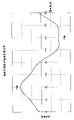
- FIG. 4 is a graph showing the magnetic flux density distribution on the rotor surface of Embodiment 1.
- FIG. FIG. 10 is a cross-sectional view showing a rotor of Embodiment 2;
- FIG. 11 is a cross-sectional view showing a rotor of Embodiment 3;
- FIG. 11 is a cross-sectional view showing a rotor of Embodiment 4;
- FIG. 11 is a vertical cross-sectional view showing a rotor according to Embodiment 5;
- FIG. 17A is a cross-sectional view taken along line 17A-17A in FIG. 16, and
- FIG. 17B is a cross-sectional view taken along line 17B-17B.
- 4A and 4B are schematic diagrams showing connection states of a U-phase coil, a V-phase coil, and a W-phase coil in each embodiment;
- FIG. It is a longitudinal section showing a compressor to which the electric motor of each embodiment can be applied.
- It is a figure which shows the refrigerating-cycle apparatus to which the electric motor of each embodiment is applicable.
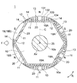
- FIG. 1 is a cross-sectional view showing electric motor 100 of Embodiment 1.
- the electric motor 100 is a synchronous motor and is incorporated in the compressor 8 ( FIG. 4 ) to drive the compression mechanism section 7 .
- the electric motor 100 has a rotor 1 rotatable around an axis Ax and a stator 5 surrounding the rotor 1 .
- a radial direction centered on the axis Ax is defined as a “radial direction”.
- a circumferential direction centered on the axis Ax is defined as a “circumferential direction” and is indicated by an arrow R in FIG. 1 and the like.
- a cross-sectional view taken along a plane parallel to the axis Ax is taken as a vertical cross-sectional view, and a cross-sectional view taken along a plane perpendicular to the axis Ax is taken as a cross-sectional view.
- the stator 5 has an annular stator core 50 and three-phase coils 6 wound around the stator core 50 by distributed winding.
- the stator core 50 is composed of a laminated body in which a plurality of magnetic steel sheets are laminated in the axial direction and fixed by caulking or the like.
- the plate thickness of the electromagnetic steel plate is, for example, 0.1 to 0.7 mm.
- the stator core 50 has an annular yoke portion 51 centered on the axis Ax and a plurality of teeth 52 extending radially inward from the yoke portion 51 .
- the outer periphery of the yoke portion 51 has a circular outer peripheral surface 51a around the axis Ax.
- Four D-cut portions 51b are formed on the outer peripheral surface 51a as plane portions parallel to the axis Ax.
- the outer peripheral surface 51a fits inside the closed container 80 of the compressor 8 (Fig. 4), which will be described later.
- a coolant passage is formed between the D-cut portion 51b and the inner peripheral surface of the sealed container 80 .
- the teeth 52 are formed on the yoke portion 51 at regular intervals in the circumferential direction.
- the number of teeth 52 is 18 here. However, the number of teeth 52 is not limited to 18, and may be two or more. Slots 53 are formed between teeth 52 adjacent in the circumferential direction. The number of slots 53 is the same as the number of teeth 52 .
- the coil 6 is wound around the stator core 50 by distributed winding.
- the coil 6 is a three-phase coil, and includes a U-phase coil 6U as a first-phase coil, a V-phase coil 6V as a second-phase coil, and a W-phase coil 6W as a third-phase coil.
- the U-phase coil 6U, the V-phase coil 6V, and the W-phase coil 6W have different radial positions.
- the U-phase coil 6U is positioned radially outermost
- the W-phase coil 6W is positioned radially innermost
- the V-phase coil 6V is positioned between the U-phase coil 6U and the W-phase coil 6W. .
- the U-phase coil 6U has three coil portions U1, U2, U3. All of the coil portions U1, U2, U3 are wound at a 3-slot pitch.
- a 3-slot pitch means that the coil is wound every 3 slots.
- V-phase coil 6V has three coil portions V1, V2, and V3. All of the coil portions V1, V2, V3 are wound at a 3-slot pitch.
- W-phase coil 6W has three coil portions W1, W2, and W3. All of the coil portions W1, W2 and W3 are wound at a 3-slot pitch.
- Each coil portion of the coils 6U, 6V, 6W has a coil side arranged in the slot 53 and a coil end extending on the axial end face of the stator core 50.
- Each of the 18 slots 53 of the stator core 50 is provided with one coil side.
- the coil portions U1, U2, U3 of the U-phase coil 6U are connected in series.
- the coil portions V1, V2, V3 of the V-phase coil 6V are connected in series, and the coil portions W1, W2, W3 of the W-phase coil 6W are connected in series.
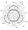
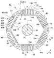
- FIG. 2 is a cross-sectional view showing the rotor 1 of Embodiment 1.
- FIG. The rotor 1 has a cylindrical rotor core 10 and permanent magnets 20 attached to the rotor core 10 .
- the rotor core 10 is composed of a laminated body in which a plurality of magnetic steel sheets are laminated in the axial direction and fixed by caulking or the like.
- the plate thickness of the electromagnetic steel plate is, for example, 0.1 to 0.7 mm.
- the rotor core 10 has an outer circumference 10a and an inner circumference 10b. Both the outer circumference 10a and the inner circumference 10b are circular with the axis Ax as the center.
- a shaft 35 is fixed to the inner circumference 10b of the rotor core 10 by shrink fitting, press fitting, adhesion, or the like.
- a central axis of the shaft 35 is the above-described axis Ax.
- a plurality of magnet insertion holes 11 are formed along the outer circumference 10 a of the rotor core 10 .
- the magnet insertion hole 11 extends in a direction orthogonal to a radial straight line passing through the longitudinal center thereof.
- the magnet insertion hole 11 is not limited to be linear, and may be V-shaped, for example.
- the magnet insertion holes 11 reach from one axial end of the rotor core 10 to the other axial end.
- a permanent magnet 20 is inserted into each magnet insertion hole 11 of the rotor core 10 . That is, six permanent magnets 20 are embedded in the rotor core 10 .
- One permanent magnet 20 constitutes one magnetic pole, and the rotor 1 has six poles.
- the number of poles of the rotor 1 is not limited to six, and may be two or more.
- the permanent magnet 20 is flat, has a width in the circumferential direction of the rotor core 10, and has a thickness in the radial direction.
- the permanent magnets 20 are composed of rare earth magnets containing, for example, neodymium (Nd), iron (Fe) and boron (B).
- These permanent magnets 20 are arranged so that the polarities of the magnetic pole faces on the outer peripheral side of adjacent permanent magnets 20 are opposite. That is, when the magnetic pole surface on the outer peripheral side of a certain permanent magnet 20 is the N pole, the magnetic pole surface on the outer peripheral side of the adjacent permanent magnet 20 is the S pole.
- the rotor 1 has three north poles and three south poles.
- a flux barrier 12 which is an air gap, is formed at both circumferential ends of the magnet insertion hole 11 in the rotor core 10. As shown in FIG. A thin portion is formed between the flux barrier 12 and the outer circumference 10 a of the rotor core 10 . The thin portion is formed to have the same width as the plate thickness of the electromagnetic steel plate in order to suppress short-circuit magnetic flux between adjacent magnetic poles.
- the center of the magnet insertion hole 11 in the circumferential direction is the pole center.
- a straight line in the radial direction passing through the pole center is called a magnetic pole center line C.
- a region between the magnet insertion hole 11 and the outer periphery 10 a in the rotor core 10 is called a magnetic pole region 18 .
- the number of magnetic pole regions 18 is the same as the number of magnet insertion holes 11 .
- rotor core 10 has six pole regions 18 .
- Slits 131 , 132 , 133 and 134 are formed in four of the six magnetic pole regions 18 .
- slits are not formed in the other two magnetic pole regions 18 . These two pole regions are circumferentially adjacent to each other.
- the magnetic pole region 18 in which the slits 131, 132, 133, 134 are formed is called “first magnetic pole region 18A”.
- the magnetic pole region 18 in which slits are not formed is referred to as "second magnetic pole region 18B”.
- slits 131, 132, 133, and 134 are formed on each side of the magnetic pole center line C in the first magnetic pole region 18A.
- the slits 131, 132, 133, and 134 are formed in this order from the magnetic pole center line C side.
- the slits 131, 132, 133, and 134 are long holes formed by punching an electromagnetic steel plate, and extend parallel to the magnetic pole center line C. Moreover, the slits 131, 132, 133, and 134 are longer in the radial direction in this order. The widths of the slits 131, 132, 133, and 134 in the circumferential direction are the same.
- the slits 131 to 134 have the effect of smoothing the magnetic flux density distribution on the surface of the rotor 1 of the magnetic flux emitted from the permanent magnet 20 and reducing torque ripple.
- the slits 131 to 134 are also called a slit group 13. FIG.
- One or more slits may be formed in the first magnetic pole region 18A. However, in order to increase the effect of smoothing the magnetic flux density distribution, it is desirable to form a plurality of slits.
- the magnet insertion hole 11 corresponding to the first magnetic pole region 18A may be called “first magnet insertion hole”, and the permanent magnet 20 in the magnet insertion hole 11 may be called “first permanent magnet”.
- the magnet insertion hole 11 corresponding to the second magnetic pole region 18B may be called “second magnet insertion hole”, and the permanent magnet 20 in the magnet insertion hole 11 may be called “second permanent magnet”.
- Side slits 14 are formed at both circumferential ends of the first magnetic pole region 18A.
- the side slit 14 is formed on the pole center side of the flux barrier 12 and extends in the circumferential direction.
- the side slits 14 have the effect of increasing the magnetic resistance in the flux barrier 12 and reducing leakage flux between adjacent magnetic poles.
- the first magnetic pole region 18A and the second magnetic pole region 18B differ in the presence or absence of slits.
- the side slits 14 are formed in the second magnetic pole region 18B as in the first magnetic pole region 18A. In this embodiment and each embodiment described later, the side slits 14 are not included in the "slits" of the first magnetic pole region 18A and the second magnetic pole region 18B.
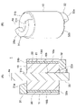
- FIG. 3(A) is a longitudinal sectional view showing the rotor 1.
- FIG. 3B is a perspective view showing the rotor 1.
- FIG. A balance weight 31 is attached to one axial end of the rotor core 10 .
- a balance weight 32 is attached to the other axial end of the rotor core 10 .
- Both the balance weights 31 and 32 are made of brass, for example.
- the balance weights 31 and 32 are fixed to the rotor core 10 by, for example, rivets (not shown).
- the balance weight 31 has a disk-shaped end plate portion 31b centered on the axis Ax, and a balance weight portion 31a formed in a part of the end plate portion 31b in the circumferential direction.
- the balance weight portion 31a is formed, for example, in a semi-annular shape centered on the axis Ax.
- a shaft 35 is inserted through the inner circumference 31 c of the balance weight 31 .
- the balance weight 32 has a disk-shaped end plate portion 32b centered on the axis Ax, and a balance weight portion 32a formed in a part of the end plate portion 32b in the circumferential direction.
- the balance weight portion 32a is formed, for example, in a semi-annular shape centered on the axis Ax.
- a shaft 35 is inserted through the inner circumference 32 c of the balance weight 32 .
- balance weight portion 31a and the end plate portion 31b are integrally formed here, they may be separate bodies.
- balance weight portion 32a and the end plate portion 32b are integrally formed here, they may be separate bodies.
- the two balance weight portions 31a and 32a are positioned symmetrically with respect to the axis Ax.
- the weights of the balance weight portions 31a and 32a are determined according to the centrifugal force generated in the compression mechanism portion 7 (FIG. 4), which will be described later.
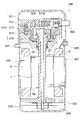
- FIG. 4 is a schematic diagram showing the basic configuration of the compressor 8 provided with the electric motor 100. As shown in FIG. Compressor 8 is here a rotary compressor, but may also be a scroll compressor (FIG. 20).
- the compressor 8 includes a compression mechanism portion 7, an electric motor 100 that drives the compression mechanism portion 7, a shaft 35 that connects the compression mechanism portion 7 and the electric motor 100, a bearing 81 that rotatably supports the shaft 35, and these. and a closed container 80 containing the .
- the closed container 80 is a container made of a steel plate.
- the stator 5 of the electric motor 100 is incorporated inside the sealed container 80 by shrink fitting, press fitting, welding, or the like.
- the bearing 81 is arranged on the side opposite to the compression mechanism portion 7 with the electric motor 100 interposed therebetween.
- the compression mechanism portion 7 includes a cylinder 70 having a cylinder chamber 71, a rolling piston 72 as a rotating portion fixed to the shaft 35, and a vane 73 (FIG. 5A) that divides the inside of the cylinder chamber 71 into a suction side and a compression side. )).
- the cylinder chamber 71 has a circular cross section centered on the axis Ax, and a rolling piston 72 attached to the shaft 35 is positioned inside the cylinder chamber 71 .
- the rolling piston 72 is cylindrical and its center is eccentric with respect to the axis Ax. When the shaft 35 rotates, the rolling piston 72 rotates eccentrically within the cylinder chamber 71 .
- FIG. 5(A) is a perspective view showing the cylinder 70.
- FIG. Vane grooves 74 into which vanes 73 are inserted are formed in the cylinder 70 .
- One end of the vane groove 74 communicates with the cylinder chamber 71, and the other end of the vane groove 74 communicates with the back pressure chamber.
- the vane 73 is provided in the vane groove 74 so as to be able to reciprocate.
- the vane 73 is pushed out from the vane groove 74 into the cylinder chamber 71 by a spring and contacts the outer peripheral surface of the rolling piston 72 .
- the cylinder 70 is formed with an intake port 75 for sucking refrigerant gas into the cylinder chamber 71 from the outside of the sealed container 80 .
- the suction port 75 is connected to the accumulator by, for example, a suction pipe.
- the cylinder 70 is also provided with a discharge port (not shown).
- a discharge port (not shown).
- the discharge valve provided at the discharge port opens and the refrigerant gas is discharged from the cylinder chamber 71 into the closed container 80 .
- FIGS. 5(B) to 5(E) are schematic diagrams showing the refrigerant compression operation in the cylinder 70.
- FIG. The vane 73 partitions the space formed by the inner peripheral surface of the cylinder chamber 71 and the outer peripheral surface of the rolling piston 72 into two working chambers.
- the working chamber communicating with the suction port 75 functions as a suction chamber that draws in low-pressure refrigerant gas
- the other working chamber functions as a compression chamber that compresses the refrigerant.
- the rolling piston 72 rotates eccentrically within the cylinder chamber 71, thereby sucking the refrigerant gas into the cylinder chamber 71 through the suction port 75 (FIG. 5(A)). , are compressed in the cylinder chamber 71 . Refrigerant gas compressed in the cylinder chamber 71 is discharged into the sealed container 80 through the discharge port.
- the balance weight portion 31a on the compression mechanism portion 7 side is arranged on the opposite side of the eccentric shaft of the rolling piston 72 with respect to the axis Ax, and the balance weight portion 32a on the bearing 81 side is arranged on the eccentric shaft of the rolling piston 72. placed on the same side as Also, the weight of the balance weight portion 31a is set to be heavier than the weight of the balance weight portion 32a.
- the centrifugal force F0 that the shaft 35 receives from the compression mechanism portion 7 is offset by the centrifugal force generated by the balance weight portions 31a and 32a of the rotor 1, thereby suppressing the vibration and noise caused by the whirling of the shaft 35. be able to.
- the centrifugal force generated by the balance weight portion 31a be a centrifugal force F1.
- Embodiment 1 ⁇ Effect of reducing vibration and noise> Next, the operation of Embodiment 1 will be described with reference to FIG.
- stator magnetic flux the magnetic flux generated by the current flowing through the coils 6 (hereinafter referred to as stator magnetic flux) travels around the magnetic pole regions 18 that are the outer peripheral portion of the rotor core 10 . flow in the direction
- the slits 131 to 134 of the rotor core 10 extend radially so as not to block the flow of the magnetic flux of the permanent magnets 20 (that is, the magnetic flux that contributes to torque generation), but only the flow of the stator magnetic flux.
- the slits 131 to 134 are formed in the first magnetic pole region 18A of the rotor core 10, but no slits are formed in the second magnetic pole region 18B.
- the second magnetic pole region 18B since the stator magnetic flux flows in the circumferential direction, the second magnetic pole region 18B is in a magnetized state, generating a magnetic attraction force that attracts the rotor 1 to the stator 5 side.
- the flow of the stator magnetic flux is interrupted by the slits 131 to 134, so the magnetic attraction force that attracts the rotor 1 toward the stator 5 is small.
- the direction of the above force f coincides with the direction of the centrifugal force F1 (FIG. 4) generated by the balance weight portion 31a. can be made This allows the rotor core 10 to play a part of the role of the balance weight portion 31a.
- FIG. 6 is a diagram showing the relationship between the U-phase coil 6U and the magnetic poles of the rotor 1 in the electric motor 100 of the first embodiment. Although the torque ripple reduction effect will be described below in relation to the U-phase coil 6U, the same applies to the V-phase coil 6V and the W-phase coil 6W.
- the stator core 50 is wound with three coil portions U1, U2, and U3 of the U-phase coil 6U. All of the coil portions U1, U2, U3 are wound at a 3-slot pitch. The winding directions of the coil portions U1, U2, U3 are the same.
- Each of the coil portions U1, U2, U3 has a coil side 61 arranged in the slot 53 and a coil end 62 extending from the axial end face of the stator core 50.
- the coil pitch of the coil portions U1, U2, and U3 of the U-phase coil 6U is 60 degrees in mechanical angle. Since the rotor 1 has six poles, the coil pitch is 180 electrical degrees. Also, the pole pitch is 60 degrees.
- the three N poles of the rotor 1 are opposed to the coil portions U1, U2, U3 of the U-phase coil 6U.
- the three south poles of the rotor 1 are opposed to the portion between the coil portions U1 and U2, the portion between the coil portions U2 and U3, and the portion between the coil portions U3 and U1 of the U-phase coil 6U. is doing.
- a portion between adjacent coil portions is called an inter-coil portion.
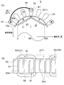
- FIG. 7A is a schematic diagram showing magnetic pole pairs including adjacent N and S poles of the rotor 1, the stator 5 facing them, and the magnetic flux density distribution on the surface of the rotor 1.
- FIG. 7B is a schematic diagram of the U-phase coil 6U of the stator 5 viewed from the rotor 1 side.
- the basic waveform representing the magnetic flux density distribution on the surface of the rotor 1 is a sine wave that is maximum at the pole center of the N pole, is 0 between the poles, and is minimum at the pole center of the S pole. is a wave.
- the S pole of the rotor 1 has a portion between the coil portions U1 and U3 of the U-phase coil 6U (a portion between the coils). ) face each other.
- This portion between the coils can be considered as a virtual coil portion whose winding direction is opposite to that of the coil portions U1 and U3, as indicated by U1' in FIG. 7(B). That is, it can be considered that the south pole of the rotor 1 is opposed to the coil portion U1' whose winding direction is opposite to that of the coil portion U1.
- the coil pitches of the coil portions U1, U2, and U3 on the N pole side of the U-phase coil 6U are 60 degrees in mechanical angle and 180 degrees in electrical angle.
- the coil pitches of the coil portions U1', U2', and U3' on the S pole side of the U-phase coil 6U are also 60 degrees in mechanical angle and 180 degrees in electrical angle.
- FIG. 8 is a diagram showing the relationship between the U-phase coil 6U and the magnetic poles of the rotor 1 in the electric motor 100C of the comparative example.
- a stator 15 of the electric motor 100C has a stator core 150 and a coil 6 wound around the stator core 150 by concentrated winding.
- a rotor 1 of the electric motor 100C is the same as the rotor 1 of the first embodiment.
- the stator core 150 has a yoke 151 and nine teeth 152.
- a U-phase coil 6U is wound around three teeth 152 out of the nine teeth 152 by concentrated winding.
- the portions wound around three teeth 152 of U-phase coil 6U are referred to as coil portions U1, U2, and U3.
- the three N poles of the rotor 1 are opposed to the coil portions U1, U2, U3 of the U-phase coil 6U.
- the three S poles of the rotor 1 face the three inter-coil portions of the U-phase coil 6U.
- These inter-coil portions can be considered as virtual coil portions U1', U2', and U3' whose winding directions are opposite to those of the coil portions U1, U2, and U3.
- the coil pitch of the coil portions U1, U2, and U3 of the U-phase coil 6U is 40 degrees in mechanical angle and 120 degrees in electrical angle.
- the coil pitches of the coil portions U1', U2', U3' on the S pole side of the U-phase coil 6U are 80 degrees in mechanical angle and 240 degrees in electrical angle.
- coil pitch is generally not used, but here, the angle between two coil sides 61 of each coil portion (eg, coil portion U1) is referred to as “coil pitch.”
- FIG. 9 is a graph showing the magnetic flux density distribution on the surface of the rotor 1 when slits are formed only in the magnetic pole region of the S pole in one magnetic pole pair of the rotor 1 .
- the even-order harmonic components are mainly 4th-order harmonic components.
- FIG. 10 is a graph showing the magnetic flux density distribution of FIG. 9 divided into a fundamental wave component and a harmonic component.
- FIG. 10 is a graph showing the range corresponding to one coil section on the pole side;
- the coil pitch of the coil portions U1, U2, and U3 on the N pole side of the U-phase coil 6U is 180 degrees in electrical angle.
- the coil pitches of the coil portions U1', U2', and U3' on the S pole side of the U-phase coil 6U are also 180 degrees in electrical angle.
- the magnetic flux interlinking with the N-pole side coil portion (eg, coil portion U1) of the U-phase coil 6U and the magnetic flux interlinking with the S-pole side coil portion (eg, coil portion U1′) , the 4th order harmonic component is cancelled.
- FIG. 11 is a graph showing the magnetic flux density distribution of FIG. 9 divided into a fundamental wave component and a harmonic component. is a graph showing the range corresponding to one coil portion of .
- the coil pitch of the coil portions U1, U2, and U3 on the N pole side of the U-phase coil 6U is 80 degrees in electrical angle.
- the coil pitch of the coil portions U1', U2', U3' on the S pole side of the U-phase coil 6U is 240 degrees in electrical angle.
- the range corresponding to one coil portion (eg, coil portion U1′) on the S pole side does not include the range corresponding to one coil portion (eg, coil portion U1) on the N pole side. contains more fourth-order harmonic components than
- the 4th harmonic component is not canceled, and the magnetic flux interlinking with the U-phase coil 6U includes the 4th harmonic component.
- the induced voltage generated in the U-phase coil 6U when the rotor 1 rotates also contains the fourth harmonic component.
- the fifth harmonic component (the fourth harmonic component of the induced voltage ⁇ the first harmonic component of the current) is superimposed on the torque ripple.
- vibration and noise are likely to occur when the resonance frequency of the compressor 8 and the frequency component of the torque ripple match.
- Embodiment 1 since the coil 6 is wound by distributed winding, the first magnetic pole region 18A and the second magnetic pole region 18B of the rotor core 10 have different forms of slits. The fourth harmonic component of the magnetic flux density distribution is canceled. Therefore, it is possible to reduce the fourth harmonic component contained in the induced voltage generated in the coil 6 when the rotor 1 rotates, thereby reducing the torque ripple.
- the U-phase coil 6U has been described as an example here, the same applies to the V-phase coil 6V and the W-phase coil 6W. Moreover, the effect of reducing harmonic components can be obtained not only by the winding method shown in FIGS.
- rotor core 10 has slits 131 to 134 in first magnetic pole region 18A and does not have slits in second magnetic pole region 18B. Therefore, the magnetic attraction force between the rotor 1 and the stator 5 differs between the first magnetic pole region 18A side and the second magnetic pole region 18B side, and the force f occurs. As a result, while reducing the size of the balance weight portion 31a, whirling of the shaft 35 during operation of the compression mechanism portion 7 can be suppressed, and vibration and noise can be suppressed.
- the coil 6 is wound by distributed winding, the harmonic component of the magnetic flux density distribution due to the difference in the form of the slit between the first magnetic pole region 18A and the second magnetic pole region 18B is reduced, and the torque ripple is reduced. can be reduced. As a result, the effect of suppressing vibration and noise can be enhanced.
- first magnetic pole regions 18A and second magnetic pole regions 18B are not limited to these numbers.
- one of the six magnetic pole regions 18 may be the second magnetic pole region 18B and the remaining five may be the first magnetic pole regions 18A.
- three consecutive magnetic pole regions 18B may be the second magnetic pole regions 18B and the remaining three magnetic pole regions 18A may be the first magnetic pole regions 18A.
- first magnetic pole region 18A has eight slits 131 to 134, the number of slits in the first magnetic pole region 18A may be one or more.
- FIG. 13 is a cross-sectional view showing rotor 1A of the second embodiment.
- a rotor 1A of the second embodiment differs from the rotor 1 of the first embodiment in that slits are formed in the second magnetic pole regions 18B.
- slits 230, 231, 232 are formed in the second magnetic pole region 18B of the rotor 1A. Specifically, a slit 230 is formed on the magnetic pole center line C, and slits 231 and 232 are formed in order from the slit 230 side on both circumferential sides of the slit 230 .
- the slits 230, 231, 232 extend parallel to the magnetic pole center line C. Moreover, the slits 230, 231, and 232 are longer in the radial direction in this order. The widths of the slits 230, 231, 232 in the circumferential direction are the same.
- a slit 130 is formed on the magnetic pole center line C1 in the first magnetic pole region 18A of the rotor 1A.
- the slit 130 has a longer radial length than the slits 131-134.
- the slits 131-134 are as described in the first embodiment.
- the slits 130 to 134 of the first magnetic pole region 18A constitute the slit group 13
- the slits 230 to 232 of the second magnetic pole region 18B constitute the slit group 23.
- the slits 230-232 of the second magnetic pole region 18B are smaller in number than the slits 130-134 of the first magnetic pole region 18A. That is, the number of slits in one second magnetic pole region 18B is smaller than the number of slits in one first magnetic pole region 18A.
- the sum of the areas of the slits 230-232 of one second magnetic pole region 18B, that is, the total area A2 is smaller than the total area A2 of the slits 130-134 of one first magnetic pole region 18A.
- the average of the radial lengths of the slits 230-232 is here the same as the average of the radial lengths of the slits 130-134, but need not necessarily be the same. Moreover, although the circumferential width of the slits 230 to 232 is the same as the circumferential width of the slits 130 to 134 here, it is not necessarily the same.
- the side slits 14 (FIG. 2) described in Embodiment 1 may be formed in the first magnetic pole region 18A and the second magnetic pole region 18B.
- the stator magnetic flux generated by the current of the coils 6 flows through the magnetic pole regions 18 of the rotor core 10 in the circumferential direction.
- the slits 130-134 block the flow of the stator magnetic flux, but in the second magnetic pole region 18B, the number of the slits 230-232 is small, so the stator magnetic flux flows around the circumference. easy to flow in any direction.
- the magnetic attraction force between the rotor 1A and the stator 5 becomes larger on the side of the second magnetic pole region 18B than on the side of the first magnetic pole region 18A, urging the rotor 1A to one side. force is generated.
- the direction of this force With the direction of the centrifugal force generated by the balance weight portion 31a, it is possible to reduce the size of the balance weight portion 31a while suppressing vibration and noise during operation of the compression mechanism portion 7.
- the number of slits in the first magnetic pole region 18A is nine, and the number of slits in the second magnetic pole region 18B is five.
- the number of slits in the second magnetic pole region 18B should be less than the number of slits in the first magnetic pole region 18A.
- the electric motor of Embodiment 2 is configured in the same manner as electric motor 100 of Embodiment 1, except for the above points.
- Embodiment 2 since the number of slits in the second magnetic pole region 18B of the rotor core 10 is smaller than the number of slits in the first magnetic pole region 18A, the rotor 1A is attached to one side. A force can be generated. As a result, vibration and noise during operation of the compression mechanism portion 7 can be suppressed while downsizing the balance weight portion 31a.
- the coil 6 is wound by distributed winding, harmonic components of the magnetic flux density distribution due to the difference in the number of slits between the first magnetic pole region 18A and the second magnetic pole region 18B are reduced, thereby reducing torque ripple. be able to. This can enhance the effect of suppressing vibration and noise.
- the generated urging force is smaller than that in the first embodiment.
- the slits 230 to 232 of the second magnetic pole region 18B have the effect of smoothing the magnetic flux density distribution on the surface of the rotor 1A, distortion of the induced voltage can be suppressed and torque ripple can be reduced.
- FIG. 14 is a cross-sectional view showing rotor 1B of the third embodiment.
- the rotor 1B of the third embodiment differs from the rotor 1A of the second embodiment in the number of slits and the circumferential width of the second magnetic pole regions 18B.
- slits 330, 331, 332, 333, and 334 are formed in the second magnetic pole region 18B of the rotor 1B. Specifically, a slit 330 is formed on the magnetic pole center line C. As shown in FIG. Slits 331 , 332 , 333 , and 334 are formed in order from the slit 330 side on both circumferential sides of the slit 330 .
- the slits 330, 331, 332, 333, 334 of the second magnetic pole region 18B extend parallel to the magnetic pole center line C. 330, 331, 332, 333, and 334 are longer in the radial direction in this order.
- Slits 130, 131, 132, 133, and 134 are formed in the first magnetic pole region 18A of the rotor 1B, as in the second embodiment.
- the slits 130-134 of the first magnetic pole region 18A constitute the slit group 13
- the slits 330-334 of the second magnetic pole region 18B constitute the slit group 33. As shown in FIG.
- the number of slits in the second magnetic pole region 18B of the rotor 1B is the same as the number of slits in the first magnetic pole region 18A.
- the circumferential width W2 of each of the slits 330-334 of the second magnetic pole region 18B is narrower than the circumferential width W1 of each of the slits 130-134 of the first magnetic pole region 18A.
- the total area A2 of the slits 330-334 of one second magnetic pole region 18B is smaller than the total area A1 of the slits 130-134 of one first magnetic pole region 18A.
- the slits 330 to 334 of the second magnetic pole region 18B have the same circumferential width here, they do not necessarily have the same circumferential width.
- the average circumferential width of the slits 330-334 of the second magnetic pole region 18B should be smaller than the average circumferential width of the slits 130-134 of the first magnetic pole region 18A.
- the average radial length of the slits 330-334 in the second pole region 18B is here the same as, but not necessarily the same as, the average radial length of the slits 130-134 in the first pole region 18A. No need.
- the side slits 14 (FIG. 2) described in Embodiment 1 may be formed in the first magnetic pole region 18A and the second magnetic pole region 18B.
- the stator magnetic flux generated by the current of the coils 6 flows through the magnetic pole regions 18 of the rotor core 10 in the circumferential direction.
- the slits 130-134 block the flow of the stator magnetic flux, but in the second magnetic pole region 18B, the width W2 of the slits 330-334 is equal to the width W1 of the slits 130-134. , the stator magnetic flux tends to flow in the circumferential direction.
- the magnetic attraction force between the rotor 1B and the stator 5 becomes larger on the side of the second magnetic pole region 18B than on the side of the first magnetic pole region 18A, urging the rotor 1B to one side. force is generated.
- the direction of this force With the direction of the centrifugal force generated by the balance weight portion 31a, it is possible to reduce the size of the balance weight portion 31a while suppressing vibration and noise during operation of the compression mechanism portion 7.
- the number of slits in the first magnetic pole region 18A is nine, and the number of slits in the second magnetic pole region 18B is also nine, but the numbers are not limited to these.
- the electric motor of Embodiment 3 is configured in the same manner as electric motor 100 of Embodiment 1 except for the above points.
- the slit width W2 of the second magnetic pole region 18B of the rotor core 10 is narrower than the slit width W1 of the first magnetic pole region 18A. can generate a force that biases the side of the As a result, vibration and noise during operation of the compression mechanism portion 7 can be suppressed while downsizing the balance weight portion 31a.
- the coil 6 is wound by distributed winding, harmonic components of the magnetic flux density distribution due to the difference in slit width between the first magnetic pole region 18A and the second magnetic pole region 18B are reduced, and torque ripple is reduced. be able to. As a result, the effect of suppressing vibration and noise can be enhanced.
- the generated urging force is smaller than in the first embodiment.
- the slits 330 to 334 of the second magnetic pole region 18B have the effect of smoothing the magnetic flux density distribution on the surface of the rotor 1B, distortion of the induced voltage can be suppressed and torque ripple can be reduced.
- the degree of freedom in arranging the slits is increased, making it easier to reduce torque ripple.
- first pole regions 18A and two were second pole regions 18B were first pole regions 18A and two were second pole regions 18B, but the first pole regions 18A and The number of second pole regions 18B is not limited to these numbers.
- FIG. 15 is a sectional view showing rotor 1C of the fourth embodiment.
- the rotor 1C of the fourth embodiment differs from the rotor 1B of the third embodiment in the radial length of the slits of the second magnetic pole regions 18B.
- slits 430, 431, 432, 433, 434 are formed in the second magnetic pole region 18B of the rotor 1C. Specifically, a slit 430 is formed on the magnetic pole center line C. As shown in FIG. Slits 431 , 432 , 433 and 434 are formed in order from the slit 430 side on both circumferential sides of the slit 430 .
- the slits 430, 431, 432, 433, 434 of the second magnetic pole region 18B extend parallel to the magnetic pole center line C.
- the slits 430, 431, 432, 433, and 434 have longer radial lengths in this order.
- slits 130, 131, 132, 133, and 134 are formed in the first magnetic pole region 18A of the rotor 1C.
- the slits 130-134 of the first magnetic pole region 18A constitute the slit group 13
- the slits 430-434 of the second magnetic pole region 18B constitute the slit group 43.
- the number of slits in the second magnetic pole region 18B of the rotor 1C is the same as the number of slits in the first magnetic pole region 18A.
- the average radial length (length L2) of the slits 430-434 in the second magnetic pole region 18B is greater than the average radial length (length L1) of the slits 130-134 in the first magnetic pole region 18A. short.
- the total area A2 of the slits 430-434 of one second magnetic pole region 18B is smaller than the total area A1 of the slits 130-134 of one first magnetic pole region 18A.
- circumferential width W2 of the slits 430 to 434 of the second magnetic pole region 18B is the same as the circumferential width W1 of the slits 130 to 134 of the first magnetic pole region 18A, it is not necessarily the same. do not have.
- the side slits 14 (FIG. 2) described in Embodiment 1 may be formed in the first magnetic pole region 18A and the second magnetic pole region 18B.
- the stator magnetic flux generated by the current of the coils 6 flows through the magnetic pole regions 18 of the rotor core 10 in the circumferential direction.
- the slits 130-134 block the flow of stator magnetic flux, but in the second pole region 18B, the length L2 of the slits 430-434 is the length of the slits 130-134. Since it is shorter than the length L1, the stator magnetic flux easily flows in the circumferential direction.
- the magnetic attraction force between the rotor 1C and the stator 5 becomes larger on the side of the second magnetic pole region 18B than on the side of the first magnetic pole region 18A, urging the rotor 1C to one side. force is generated.
- the direction of this force With the direction of the centrifugal force generated by the balance weight portion 31a, it is possible to reduce the size of the balance weight portion 31a while suppressing vibration and noise during operation of the compression mechanism portion 7.
- the number of slits in the first magnetic pole region 18A is nine, and the number of slits in the second magnetic pole region 18B is also nine, but the numbers are not limited to these.
- the electric motor of Embodiment 4 is configured in the same manner as electric motor 100 of Embodiment 1 except for the above points.
- the slit length L2 of the second magnetic pole region 18B of the rotor core 10 is shorter than the slit length L1 of the first magnetic pole region 18A, the rotor 1C to one side. As a result, vibration and noise during operation of the compression mechanism portion 7 can be suppressed while downsizing the balance weight portion 31a.
- the coil 6 is wound by distributed winding, harmonic components of the magnetic flux density distribution due to the difference in slit length between the first magnetic pole region 18A and the second magnetic pole region 18B are reduced, and torque ripple is reduced. can do. This can enhance the effect of suppressing vibration and noise.
- the generated urging force is smaller than that in the first embodiment.
- the slits 430 to 434 of the second magnetic pole region 18B can smooth the magnetic flux density distribution on the surface of the rotor 1C, the distortion of the induced voltage can be suppressed and the torque ripple can be reduced.
- the length of the slit of the second magnetic pole region 18B is shorter than in the second and third embodiments, the effect of smoothing the magnetic flux density distribution on the surface of the rotor 1C is reduced. , but the stator magnetic flux is more likely to flow through the second pole region 18B, so a greater biasing force can be generated.
- first pole regions 18A and two were second pole regions 18B were first pole regions 18A and two were second pole regions 18B, but the first pole regions 18A and The number of second pole regions 18B is not limited to these numbers.
- FIG. 16 is a cross-sectional view showing rotor 1D of the fifth embodiment.
- Rotor 1D of the fifth embodiment differs from rotor 1 of the first embodiment in that rotor core 10 has two core portions 101 and 102 in the axial direction.
- FIG. 17(A) is a cross-sectional view taken along line 17A-17A in FIG. 16, showing the first core portion 101.
- FIG. 17B is a cross-sectional view taken along line 17B-17B in FIG. 16, showing the second core portion 102.
- FIG. 17(A) is a cross-sectional view taken along line 17A-17A in FIG. 16, showing the first core portion 101.
- FIG. 17B is a cross-sectional view taken along line 17B-17B in FIG. 16, showing the second core portion 102.
- FIG. 17(A) is a cross-sectional view taken along line 17A-17A in FIG. 16, showing the first core portion 101.
- FIG. 17B is a cross-sectional view taken along line 17B-17B in FIG. 16, showing the second core portion 102.
- the first core portion 101 has four first magnetic pole regions 18A and two second magnetic pole regions 18B.
- the second core portion 102 has four first magnetic pole regions 18A and two second magnetic pole regions 18B.
- the second magnetic pole region 18B of the first core portion 101 and the second magnetic pole region 18B of the second core portion 102 are positioned with respect to the axis Ax. Circumferential positions are different from each other.
- the second magnetic pole region 18B of the first core portion 101 and the second magnetic pole region 18B of the second core portion 102 are positioned symmetrically with respect to the axis Ax.
- the first magnetic pole region 18A of the first core portion 101 and the second magnetic pole region 18B of the second core portion 102 overlap to form the second magnetic pole region of the first core portion 101.
- 18B and the first magnetic pole region 18A of the second core portion 102 overlap.
- the directions of the biasing forces generated by the first core portion 101 and the second core portion 102 of the rotor core 10 are opposite to each other.
- the circumferential position of the second magnetic pole region 18B of the first core portion 101 is aligned with the circumferential position of the balance weight portion 31a, and the circumferential position of the second magnetic pole region 18B of the second core portion 102 is aligned with the balance weight portion 31a.
- the balance weight portions 31a and 32a can be miniaturized by aligning them with the circumferential position of the weight portion 32a.
- the first core portion 101 has an axial dimension H1
- the second core portion 102 has an axial dimension H2.
- the ratio of the dimensions H1 and H2 can be determined according to the degree of miniaturization of the balance weight portions 31a and 32a.
- slits are not formed in the second magnetic pole regions 18B of the core portions 101 and 102.
- the second pole region 18B may have fewer slits than the first pole region 18A.
- the second magnetic pole region 18B may be formed with slits narrower in width than the slits of the first magnetic pole region 18A.
- the second magnetic pole region 18B may be provided with slits shorter in length than the slits of the first magnetic pole region 18A.
- the electric motor of Embodiment 5 is configured in the same manner as electric motor 100 of Embodiment 1 except for the above points.
- rotor core 10 has first core portion 101 and second core portion 102, and second magnetic pole region 18B of first core portion 101 and second magnetic pole region 18B.
- the second magnetic pole regions 18B of the two core portions 102 are located symmetrically with respect to the axis Ax. Therefore, both the balance weight portions 31a and 32a can be miniaturized, and vibration and noise during operation of the compression mechanism portion 7 can be suppressed.
- four of the six magnetic pole regions 18 of the core portions 101 and 102 were the first magnetic pole regions 18A and two were the second magnetic pole regions 18B.
- the numbers of 18A and second pole regions 18B are not limited to these numbers.
- FIG. 18(A) is a schematic diagram showing an example of the connection state of the U-phase coil 6U, the V-phase coil 6V, and the W-phase coil 6W.
- the coil portions U1, U2 and U3 of the U-phase coil 6U are connected in series, the coil portions V1, V2 and V3 of the V-phase coil 6V are connected in series, and the coil portions W1, W2 and W3 of the W-phase coil 6W are connected in series. It is connected to the.
- the U-phase coil 6U, the V-phase coil 6V, and the W-phase coil 6W are connected at the neutral point N. That is, they are Y-connected.
- FIG. 18(B) is a schematic diagram showing another example of the connection state of the U-phase coil 6U, the V-phase coil 6V, and the W-phase coil 6W.
- the U-phase coil 6U, the V-phase coil 6V, and the W-phase coil 6W are connected by delta connection.
- the coil portions of the coils 6U, 6V, and 6W of each phase are connected in series.
- the coil portions of the coils 6U, 6V, 6W (for example, the coil of the U-phase coil 6U)
- the magnetic flux interlinking the parts U1, U2, U3) becomes non-uniform. Therefore, if the coil portions of the coils 6U, 6V, 6W are connected in parallel, the current flowing through each of the coils 6U, 6V, 6W becomes nonuniform, resulting in loss.
- each phase coil is not limited to three. Assuming that the number of coil portions constituting each phase coil is N (N is an integer equal to or greater than 2), it is sufficient that N coil portions are connected in series.
- the first to fifth embodiments described above can be combined as appropriate.
- the number of slits in the second magnetic pole region 18B can be reduced, the width narrowed, and the length increased.
- FIG. 19 is a longitudinal sectional view showing compressor 300.
- the compressor 8 whose main part is shown in FIG. 4 is a rotary compressor
- the electric motor 100 of each embodiment can also be applied to a compressor 300 as a scroll compressor shown in FIG.
- the compressor 300 supports a compression mechanism portion 310, an electric motor 100 that drives the compression mechanism portion 310, a shaft 35 that connects the compression mechanism portion 310 and the electric motor 100, and a lower end portion (secondary shaft portion) of the shaft 35. It has a subframe 303 and a sealed container 301 in which these are accommodated. Refrigerant oil 304 is stored in an oil sump 305 at the bottom of the sealed container 301 .
- the compression mechanism section 310 includes a fixed scroll 311 and an orbiting scroll 312 , an Oldham ring 313 , a compliant frame 314 and a guide frame 315 . Both the fixed scroll 311 and the orbiting scroll 312 have plate-like spiral teeth and are combined to form a compression chamber 316 .
- the fixed scroll 311 has a discharge port 311 a for discharging the refrigerant compressed in the compression chamber 316 .
- a suction pipe 306 passing through the sealed container 301 is press-fitted into the fixed scroll 311 .
- a discharge pipe 307 for discharging high-pressure refrigerant gas discharged from a discharge port 311 a of the fixed scroll 311 is provided so as to pass through the sealed container 301 .
- the electric motor 100 is incorporated inside the sealed container 301 by shrink fitting.
- a glass terminal 308 for electrically connecting the stator 5 of the electric motor 100 and the drive circuit is fixed to the sealed container 301 by welding.
- the operation of the compressor 300 is as follows.
- the shaft 35 rotates together with the rotor 1 .
- the orbiting scroll 312 oscillates, changing the volume of the compression chamber 316 between the fixed scroll 311 and the orbiting scroll 312 .
- the refrigerant gas is sucked from the suction pipe 306 into the compression chamber 316 and compressed.
- the high-pressure refrigerant gas compressed in the compression chamber 316 is discharged from the discharge port 311a of the fixed scroll 311 into the sealed container 301 and discharged from the discharge pipe 307 to the outside. Also, part of the refrigerant gas discharged from compression chamber 316 into sealed container 301 passes through a hole provided in electric motor 100 and cools electric motor 100 .
- the electric motor 100 of each embodiment described above suppresses vibration and noise, the quietness of the compressor 300 including the electric motor 100 can be improved.
- FIG. 23 is a diagram showing the configuration of the refrigeration cycle device 400.
- the refrigeration cycle device 400 is, for example, an air conditioner.
- the refrigeration cycle device 400 includes a compressor 401 , a condenser 402 , an expansion device (decompression device) 403 and an evaporator 404 .
- Compressor 401, condenser 402, expansion device 403, and evaporator 404 are connected by refrigerant pipe 407 to form a refrigeration cycle. That is, the refrigerant circulates through the compressor 401 , the condenser 402 , the expansion device 403 and the evaporator 404 in this order.
- the compressor 401 , the condenser 402 and the expansion device 403 are provided in the outdoor unit 410 .
- Compressor 401 is composed of compressor 300 described with reference to FIG.
- the outdoor unit 410 is provided with an outdoor fan 405 that blows air to the condenser 402 .
- Evaporator 404 is provided in indoor unit 420 .
- This indoor unit 420 is provided with an indoor fan 406 that blows air to the evaporator 404 .
- the operation of the refrigeration cycle device 400 is as follows. Compressor 401 compresses the sucked refrigerant and sends it out.
- the condenser 402 exchanges heat between the refrigerant flowing from the compressor 401 and the outdoor air, condenses and liquefies the refrigerant, and sends the liquefied refrigerant to the refrigerant pipe 407 .
- Outdoor fan 405 supplies outdoor air to condenser 402 .
- the expansion device 403 adjusts the pressure of the refrigerant flowing through the refrigerant pipe 407 .
- the evaporator 404 exchanges heat between the refrigerant brought to a low pressure state by the expansion device 403 and the indoor air.
- the refrigerant evaporates through heat exchange with the air and is sent out to the refrigerant pipe 407 .
- the indoor fan 406 supplies the air cooled by heat exchange in the evaporator 404 indoors.
- the electric motor 100 of each embodiment reduces vibration and noise, the quietness of the refrigeration cycle apparatus 400 having the compressor 401 equipped with the electric motor 100 can be improved.
Landscapes
- Engineering & Computer Science (AREA)
- Power Engineering (AREA)
- Permanent Field Magnets Of Synchronous Machinery (AREA)
- Iron Core Of Rotating Electric Machines (AREA)
Priority Applications (2)
| Application Number | Priority Date | Filing Date | Title |
|---|---|---|---|
| PCT/JP2021/006989 WO2022180717A1 (ja) | 2021-02-25 | 2021-02-25 | 電動機、圧縮機および冷凍サイクル装置 |
| JP2023501743A JP7479562B2 (ja) | 2021-02-25 | 2021-02-25 | 電動機、圧縮機および冷凍サイクル装置 |
Applications Claiming Priority (1)
| Application Number | Priority Date | Filing Date | Title |
|---|---|---|---|
| PCT/JP2021/006989 WO2022180717A1 (ja) | 2021-02-25 | 2021-02-25 | 電動機、圧縮機および冷凍サイクル装置 |
Publications (1)
| Publication Number | Publication Date |
|---|---|
| WO2022180717A1 true WO2022180717A1 (ja) | 2022-09-01 |
Family
ID=83047872
Family Applications (1)
| Application Number | Title | Priority Date | Filing Date |
|---|---|---|---|
| PCT/JP2021/006989 Ceased WO2022180717A1 (ja) | 2021-02-25 | 2021-02-25 | 電動機、圧縮機および冷凍サイクル装置 |
Country Status (2)
| Country | Link |
|---|---|
| JP (1) | JP7479562B2 (https=) |
| WO (1) | WO2022180717A1 (https=) |
Citations (3)
| Publication number | Priority date | Publication date | Assignee | Title |
|---|---|---|---|---|
| JP2000069695A (ja) * | 1998-08-21 | 2000-03-03 | Matsushita Electric Ind Co Ltd | 永久磁石ロータ |
| JP2013118788A (ja) * | 2011-12-05 | 2013-06-13 | Samsung Electronics Co Ltd | ブラシレスモータ |
| JP2014166016A (ja) * | 2013-02-25 | 2014-09-08 | Hitachi Appliances Inc | 永久磁石同期機およびこれを用いた圧縮機 |
-
2021
- 2021-02-25 WO PCT/JP2021/006989 patent/WO2022180717A1/ja not_active Ceased
- 2021-02-25 JP JP2023501743A patent/JP7479562B2/ja active Active
Patent Citations (3)
| Publication number | Priority date | Publication date | Assignee | Title |
|---|---|---|---|---|
| JP2000069695A (ja) * | 1998-08-21 | 2000-03-03 | Matsushita Electric Ind Co Ltd | 永久磁石ロータ |
| JP2013118788A (ja) * | 2011-12-05 | 2013-06-13 | Samsung Electronics Co Ltd | ブラシレスモータ |
| JP2014166016A (ja) * | 2013-02-25 | 2014-09-08 | Hitachi Appliances Inc | 永久磁石同期機およびこれを用いた圧縮機 |
Also Published As
| Publication number | Publication date |
|---|---|
| JP7479562B2 (ja) | 2024-05-08 |
| JPWO2022180717A1 (https=) | 2022-09-01 |
Similar Documents
| Publication | Publication Date | Title |
|---|---|---|
| US8405272B2 (en) | Self-starting permanent magnet synchronous motor and compressor and refrigeration cycle using the same | |
| JP7362801B2 (ja) | 電動機、圧縮機、送風機、及び冷凍空調装置 | |
| WO2018203364A1 (ja) | ロータ、電動機、圧縮機および空気調和装置 | |
| US10879760B2 (en) | Permanent-magnet-embedded electric motor for compressor, compressor, and refrigeration cycle device | |
| CN111033947B (zh) | 转子、电动机、压缩机及空调装置 | |
| CN110663160B (zh) | 电动机、压缩机及空气调节装置 | |
| US11863020B2 (en) | Motor, compressor, and air conditioner | |
| US11831204B2 (en) | Rotor, motor, compressor, and air conditioner | |
| WO2020170418A1 (ja) | モータ、圧縮機および空気調和装置 | |
| EP4478585B1 (en) | Rotating electrical machine, manufacturing method therefor, compressor, blower, and refrigeration device equipped with rotating electrical machine | |
| US20220224193A1 (en) | Compressor and air conditioner | |
| JP7450805B2 (ja) | モータ、圧縮機および冷凍サイクル装置 | |
| WO2023032134A1 (ja) | 電動機、圧縮機および冷凍サイクル装置 | |
| US20230116012A1 (en) | Rotor, motor, compressor, air conditioner, and manufacturing method of rotor | |
| JP7479562B2 (ja) | 電動機、圧縮機および冷凍サイクル装置 | |
| JPWO2016199226A1 (ja) | 圧縮機用電動機、圧縮機、および冷凍サイクル装置 | |
| JP7433420B2 (ja) | ロータ、モータ、圧縮機および空気調和装置 | |
| WO2022244113A1 (ja) | 電動機、圧縮機および冷凍サイクル装置 | |
| WO2023181238A1 (ja) | 固定子、電動機、圧縮機および冷凍サイクル装置 | |
| JP7292424B2 (ja) | モータ、圧縮機および空気調和装置 | |
| WO2023037438A1 (ja) | ロータ、モータ、圧縮機および冷凍サイクル装置 | |
| WO2025203429A1 (ja) | ステータ、電動機、圧縮機および冷凍サイクル装置 | |
| US20230198328A1 (en) | Stator, motor, compressor, refrigeration cycle apparatus, and air conditioner | |
| WO2024004202A1 (ja) | 固定子、電動機、圧縮機および冷凍サイクル装置 | |
| WO2025158644A1 (ja) | 電動機、圧縮機および冷凍サイクル装置 |
Legal Events
| Date | Code | Title | Description |
|---|---|---|---|
| 121 | Ep: the epo has been informed by wipo that ep was designated in this application |
Ref document number: 21927819 Country of ref document: EP Kind code of ref document: A1 |
|
| ENP | Entry into the national phase |
Ref document number: 2023501743 Country of ref document: JP Kind code of ref document: A |
|
| NENP | Non-entry into the national phase |
Ref country code: DE |
|
| 122 | Ep: pct application non-entry in european phase |
Ref document number: 21927819 Country of ref document: EP Kind code of ref document: A1 |