WO2022180664A1 - モータ、圧縮機および冷凍サイクル装置 - Google Patents
モータ、圧縮機および冷凍サイクル装置 Download PDFInfo
- Publication number
- WO2022180664A1 WO2022180664A1 PCT/JP2021/006780 JP2021006780W WO2022180664A1 WO 2022180664 A1 WO2022180664 A1 WO 2022180664A1 JP 2021006780 W JP2021006780 W JP 2021006780W WO 2022180664 A1 WO2022180664 A1 WO 2022180664A1
- Authority
- WO
- WIPO (PCT)
- Prior art keywords
- rotor
- motor
- core
- stator
- motor according
- Prior art date
- Legal status (The legal status is an assumption and is not a legal conclusion. Google has not performed a legal analysis and makes no representation as to the accuracy of the status listed.)
- Ceased
Links
Images









Classifications
-
- H—ELECTRICITY
- H02—GENERATION; CONVERSION OR DISTRIBUTION OF ELECTRIC POWER
- H02K—DYNAMO-ELECTRIC MACHINES
- H02K3/00—Details of windings
- H02K3/32—Windings characterised by the shape, form or construction of the insulation
- H02K3/34—Windings characterised by the shape, form or construction of the insulation between conductors or between conductor and core, e.g. slot insulation
- H02K3/345—Windings characterised by the shape, form or construction of the insulation between conductors or between conductor and core, e.g. slot insulation between conductor and core, e.g. slot insulation
-
- H—ELECTRICITY
- H02—GENERATION; CONVERSION OR DISTRIBUTION OF ELECTRIC POWER
- H02K—DYNAMO-ELECTRIC MACHINES
- H02K1/00—Details of the magnetic circuit
- H02K1/06—Details of the magnetic circuit characterised by the shape, form or construction
- H02K1/12—Stationary parts of the magnetic circuit
- H02K1/16—Stator cores with slots for windings
-
- H—ELECTRICITY
- H02—GENERATION; CONVERSION OR DISTRIBUTION OF ELECTRIC POWER
- H02K—DYNAMO-ELECTRIC MACHINES
- H02K3/00—Details of windings
- H02K3/30—Windings characterised by the insulating material
-
- H—ELECTRICITY
- H02—GENERATION; CONVERSION OR DISTRIBUTION OF ELECTRIC POWER
- H02K—DYNAMO-ELECTRIC MACHINES
- H02K3/00—Details of windings
- H02K3/32—Windings characterised by the shape, form or construction of the insulation
- H02K3/34—Windings characterised by the shape, form or construction of the insulation between conductors or between conductor and core, e.g. slot insulation
-
- H—ELECTRICITY
- H02—GENERATION; CONVERSION OR DISTRIBUTION OF ELECTRIC POWER
- H02K—DYNAMO-ELECTRIC MACHINES
- H02K2213/00—Specific aspects, not otherwise provided for and not covered by codes H02K2201/00 - H02K2211/00
- H02K2213/03—Machines characterised by numerical values, ranges, mathematical expressions or similar information
Definitions
- the present disclosure relates to motors, compressors, and refrigeration cycle devices.
- a motor has a rotor with permanent magnets and an annular stator surrounding the rotor.
- the stator has a plurality of slots, and windings are accommodated in the slots (for example, Patent Document 1).
- Aluminum wires are increasingly being used for windings instead of conventional copper wires.
- the magnetic flux emitted from the permanent magnets of the rotor flows around the slots of the stator and returns to the rotor. That is, a magnetic path is formed so as to surround the slot.
- the length of the magnetic path tends to be long and iron loss tends to be large.
- the present disclosure has been made to solve the above problems, and aims to suppress a decrease in motor efficiency.
- the motor of the present disclosure includes a rotor having an annular rotor core centered on the axis, permanent magnets attached to the rotor core, a core back surrounding the rotor from the outside in a radial direction centered on the axis, and a core back extending from the rotor. and a stator core having a tooth extending toward and a slot adjacent to the tooth in the circumferential direction around the axis, an insulating part attached to the tooth, and a conductor made of aluminum and having an insulating part and a stator having windings wound on the teeth.
- the rotor core radius Dr, the stator core radius Ds, and the slot area S satisfy 25 mm ⁇ Dr ⁇ 30 mm, 0.47 ⁇ Dr/Ds ⁇ 0.56, and 0.089 ⁇ S/Dr 2 ⁇ 0.224. do.
- iron loss and copper loss can be reduced, thereby suppressing a decrease in motor efficiency.
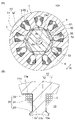
- FIG. 1 is a cross-sectional view showing a motor according to Embodiment 1;
- FIG. 2 is a cross-sectional view showing part of the stator of Embodiment 1;
- FIG. FIG. 2 is a cross-sectional view showing teeth, insulating portions, and windings of Embodiment 1;
- FIG. 2 is a schematic diagram showing a cross-sectional structure of a winding according to Embodiment 1;
- FIG. 4A is a cross-sectional view showing a motor of Comparative Example 1, and
- FIG. 4B is a cross-sectional view showing a part of a stator;
- FIG. 8A is a sectional view showing a motor of Comparative Example 2
- FIG. 8B is a sectional view showing a part of a stator;
- FIG. 8A is a sectional view showing a motor of Comparative Example 2
- FIG. 8B is a sectional view showing a part of a stator;
- FIG. 8A
- FIG. 8A is a sectional view showing a motor of Comparative Example 3, and FIG. 8B is a sectional view showing a part of a stator;
- FIG. 10A is a cross-sectional view showing a motor of Comparative Example 4, and
- FIG. 8B is a cross-sectional view showing a part of a stator;
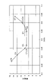
- 4 is a graph showing the relationship between the radius ratio Dr/Ds between the rotor core and the stator core and iron loss.
- 4 is a graph showing the relationship between the ratio S/Dr 2 of the slot area S and the square of the radius of the rotor core and iron loss.
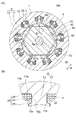
- FIG. 5 is a cross-sectional view showing a motor according to Embodiment 2;
- FIG. 5 is a cross-sectional view showing a motor according to Embodiment 2;
- FIG. 5 is a cross-sectional view showing a motor according to Embodiment 2;
- FIG. 5 is a cross-sectional view showing a motor according to Em
- FIG. 7A is a cross-sectional view (A) showing a part of the stator of Embodiment 2, and a cross-sectional view (B) showing teeth, an insulating portion, and windings.
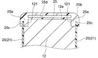
- FIG. 10 is a schematic diagram showing teeth, an insulator, and an insulating film in one configuration example of Embodiment 2; It is sectional drawing (A) which shows some stators of a comparative example, and sectional drawing (B) which shows teeth, an insulating part, and winding.
- FIG. 11 is a cross-sectional view showing a motor according to Embodiment 3; It is a cross-sectional view showing a motor of a modification.
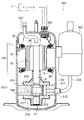
- FIG. 10 is a longitudinal sectional view showing a compressor to which the motors of the embodiments and modifications are applicable;
- FIG. 18 is a diagram showing a refrigeration cycle device to which the compressor of FIG. 17 can be applied;
- FIG. 1 is a cross-sectional view showing motor 100 of Embodiment 1.
- FIG. Motor 100 shown in FIG. 1 is a three-phase synchronous motor.
- a motor 100 is used, for example, in a compressor 300 ( FIG. 17 ), and is driven and controlled by an inverter 7 .
- the motor 100 has a rotor 5 having a shaft 6 which is a rotating shaft, and a stator 1 provided so as to surround the rotor 5 .
- the stator 1 is incorporated inside a closed container 301 of a compressor 300 (FIG. 17), which will be described later.
- the direction of the axis Ax which is the center of rotation of the rotor 5, that is, the central axis of the shaft 6, will be referred to as the "axial direction".
- a radial direction centered on the axis Ax is defined as a “radial direction”.
- a circumferential direction centered on the axis Ax is defined as a “circumferential direction” and is indicated by an arrow R in FIG. 1 and the like.
- the rotor 5 has a cylindrical rotor core 50 centered on the axis Ax and permanent magnets 55 attached to the rotor core 50 .
- the rotor core 50 is formed by laminating a plurality of electromagnetic steel sheets in the axial direction and fixing them by caulking or the like.
- the plate thickness of the electromagnetic steel plate is 0.1 to 0.7 mm, here it is 0.35 mm.
- a center hole 53 is formed in the radial center of the rotor core 50 .
- the shaft 6 is fixed to the center hole 53 of the rotor core 50 by shrink fitting or press fitting.
- the rotor core 50 has a circular outer periphery.
- the rotor core 50 has a radius Dr.
- Radius Dr is the distance from axis Ax to the outer circumference of rotor core 50 .
- the radius Dr of the rotor core 50 is 25-30 mm, and for example is 29.25 mm.
- a plurality of magnet insertion holes 51 into which permanent magnets 55 are inserted are formed along the outer circumference of the rotor core 50 .
- One magnet insertion hole 51 corresponds to one magnetic pole, and the space between the adjacent magnet insertion holes 51 is a pole-to-pole portion.
- the number of magnet insertion holes 51 is six here. In other words, the number of poles is six. However, the number of poles is not limited to six, and may be two or more.
- the magnet insertion hole 51 extends linearly in a direction orthogonal to a radial straight line passing through its circumferential center, that is, the pole center.
- One permanent magnet 55 is inserted into each magnet insertion hole 51 .
- Two or more permanent magnets 55 may be arranged in each magnet insertion hole 51 .
- the magnet insertion hole 51 is not limited to be linear, and may be V-shaped, for example.
- the permanent magnet 55 is flat and has a width in the circumferential direction of the rotor core 50 and a thickness in the radial direction.
- the permanent magnets 55 are made of rare earth magnets containing, for example, neodymium (Nd), iron (Fe) and boron (B).
- Rare earth magnets have the property that their coercive force decreases as the temperature rises, and the rate of decrease is -0.5 to -0.6%/K.
- a coercive force of 1100 to 1500 A/m is required to prevent demagnetization of the rare earth magnets at the maximum load expected in the compressor.
- the coercive force at room temperature that is, at 20°C must be 1800 to 2300 A/m.
- Dy dysprosium
- the coercive force of the rare earth magnet at room temperature is 1800 A/m without adding Dy, and becomes 2300 A/m with the addition of 2 wt % Dy.
- the addition of Dy causes an increase in manufacturing cost and a decrease in residual magnetic flux density. Therefore, it is desirable not to add Dy or to add as little Dy as possible.
- flux barriers 52 are formed as leakage magnetic flux suppression holes at both circumferential ends of the magnet insertion holes 51 .
- a thin portion is formed between the flux barrier 52 and the outer circumference of the rotor core 50 .
- the width of the thin portion is set to be the same as the plate thickness of the electromagnetic steel plate of the rotor core 50 in order to suppress magnetic flux short-circuiting between adjacent magnetic poles.
- the stator 1 has a stator core 10 surrounding a rotor core 50 from the outside in the radial direction, and windings 3 wound around the stator core 10 .
- the stator core 10 is formed by laminating a plurality of magnetic steel sheets in the axial direction and fixing them by caulking or the like.
- the plate thickness of the electromagnetic steel sheet is 0.1 to 0.7 mm, and 0.35 mm is particularly desirable.
- the stator core 10 has an annular core back 11 centered on the axis Ax and a plurality of teeth 12 extending radially inward from the core back 11 .
- Core back 11 has an inner periphery 11a (FIG. 2) and an outer periphery 11b.
- the stator core 10 has a radius Ds.
- the radius Ds is the distance from the axis Ax to the outer circumference 11b of the core back 11 .
- a radius Ds of the stator core 10 is, for example, 53.5 mm.
- the teeth 12 are formed at regular intervals in the circumferential direction.
- the number of teeth 12 is nine here. However, the number of teeth 12 is not limited to nine, and may be two or more.
- Slots 13, which are spaces for accommodating windings 3, are formed between teeth 12 adjacent in the circumferential direction. The number of slots 13 is the same as the number of teeth 12, here nine.
- the area of the slot 13 on the plane perpendicular to the axis Ax is simply referred to as "the area of the slot 13". Also, the total area of the nine slots 13 of the stator core 10 is referred to as "slot area S".
- the slot area S in the stator core 10 of Embodiment 1 is, for example, 93.5 mm 2 .
- FIG. 2 is a cross-sectional view showing part of the stator 1.
- FIG. A radial straight line passing through the circumferential centers of the teeth 12 is defined as a tooth center line T.
- the tooth 12 has a tooth crest 12a at its radially inner end.
- the tooth crest 12 a faces the rotor 5 .
- the tip portion including the crest surface 12 a of the tooth 12 protrudes to both sides in the circumferential direction from the other portion of the tooth 12 .
- the teeth 12 have side surfaces 12b at both ends in the circumferential direction.
- the side surface 12b is parallel to the teeth centerline T.
- An inclined surface 12c inclined with respect to the tooth center line T is formed radially inward of the side surface 12b of the tooth 12, that is, on the rotor 5 side, and an end surface 12d is formed between the inclined surface 12c and the tooth top surface 12a.
- the inner periphery 11a of the core back 11 extends linearly from the base of the side surface 12b of the tooth 12 at an angle of 90 degrees with respect to the side surface 12b.
- the inner circumference 11a of the core back 11 may extend in an arc shape from the root portion of the side surface 12b of the tooth 12 .
- the insulating film 20 is attached to the inner surface of the slot 13 of the stator core 10 as an insulating portion.
- the insulating film 20 is made of resin such as polyethylene terephthalate (PET).
- the insulating film 20 has a first portion 21 covering the side surface 12b of the tooth 12, a second portion 22 covering the inner periphery 11a of the core back 11, and a third portion 23 covering the inclined surface 12c and the end surface 12d of the tooth 12. have.
- An insulator 25 (see FIG. 12(B)) is provided as an insulating portion at the axial end of the stator core 10 .
- the insulator 25 is made of resin such as polybutylene terephthalate (PBT). Winding 3 is wound around tooth 12 via insulating film 20 and insulator 25 .
- the winding 3 is made of magnet wire and wound around each tooth 12 by concentrated winding.
- the number of turns of the winding 3 on one tooth 12 is, for example, 80 turns.
- the windings 3 are connected by a three-phase Y-connection.
- the wire diameter and number of turns of the winding 3 are set according to the required characteristics of the motor 100, the supply voltage, and the area of the slot 13. FIG.
- FIG. 3 is a cross-sectional view showing teeth 12, insulating film 20 and winding 3.
- FIG. The windings 3 are wound around the side surfaces 12b of the teeth 12 in a bale-like manner.
- Bale stacking means that one winding portion (indicated by symbol W in FIG. 3) of the k+1th layer (k ⁇ 1) of the winding 3 is wound so as to be in contact with two winding portions of the kth layer. Say things.
- the space factor of the windings 3 in the slot 13 can be increased.
- the space factor is the ratio of the total cross-sectional area of the winding portion in the slot 13 to the area of the slot 13 .
- the contact area between the winding parts increases, the heat of the windings 3 can be efficiently radiated to the stator core 10, and the temperature rise of the windings 3 can be reduced. Suppressed.
- the windings 3 are shown in four layers for convenience of illustration, but the number of layers of the windings 3 is arbitrary. Moreover, the winding 3 may be in contact with not only the first portion 21 of the insulating film 20 but also the second portion 22 and the third portion 23 .
- FIG. 4 is a diagram showing the cross-sectional shape of the winding 3.
- the winding 3 has a conductor 31 and a coating 32 surrounding the conductor 31 .
- Conductor 31 is made of aluminum.
- the coating 32 is made of an insulating resin such as polyesterimide or polyamideimide. Such a winding whose conductor is made of aluminum is also called an aluminum wire.
- the winding 3 has an outer diameter d1 of 0.7 to 1.2 mm.
- Embodiment 1 Next, the operation of Embodiment 1 will be described.
- the magnetic flux that has flowed into the stator core 10 from the rotor 5 flows around the slots 13 and returns to the rotor 5 as indicated by L in FIG. Therefore, a magnetic path is formed in stator core 10 so as to surround slot 13 .
- Iron loss generated in stator 1 depends on the length of the magnetic path in stator core 10 . Therefore, the larger the slot area S, the larger the iron loss, and the smaller the slot area S, the smaller the iron loss.
- the motors 100 of Configuration Examples 1 to 3 of Embodiment 1 have the shape described with reference to FIG. 1, and the radius Dr and slot area S of the rotor core 50 are different.
- Motor 100 of Configuration Example 1 of Embodiment 1 has radius Dr of rotor core 50 of 29.25 mm, radius Ds of stator core 10 of 53.5 mm, and slot area S of 93.5 mm 2 .
- radius ratio the ratio of radii of rotor core 50 to stator core 10 (hereinafter simply referred to as radius ratio) Dr/Ds is 0.55.
- the ratio S/Dr2 between the slot area S and the square of the radius Dr of the rotor core 50 is 0.109.
- the radius Dr of the rotor core 50 is 30.0 mm
- the radius Ds of the stator core 10 is 53.5 mm
- the slot area S is 80.0 mm 2 .
- the radius ratio Dr/Ds is 0.56
- the ratio S/Dr2 of the slot area S to the square of the radius Dr is 0.089.
- the radius Dr of the rotor core 50 is 25.0 mm
- the radius Ds of the stator core 10 is 53.5 mm
- the slot area S is 140.0 mm 2 .
- the radius ratio Dr/Ds is 0.47
- the ratio S/Dr2 of the slot area S to the square of the radius Dr is 0.224.
- FIG. 5A is a cross-sectional view showing the motor 101 of Comparative Example 1.
- FIG. The motor 101 of Comparative Example 1 has 6 poles and 9 slots.
- the radius Dr of the rotor core 50 is 24.0 mm
- the radius Ds of the stator core 10 is 53.5 mm
- the slot area S is 132.0 mm 2 .
- the radius ratio Dr/Ds is 0.45
- the ratio S/Dr2 of the slot area S to the square of the radius Dr is 0.229.
- FIG. 5(B) is a sectional view showing part of the stator 1 of the motor 101 of Comparative Example 1.
- FIG. The inner periphery 11a of the core-back 11 of Comparative Example 1 extends linearly from the root portion of the side surface 12b of the tooth 12 at an angle of 90 degrees with respect to the side surface 12b.
- the windings 3 are shown in simplified form in FIG. 5(B), they are wound around the teeth 12 in a bale-like manner.
- FIG. 6A is a cross-sectional view showing the motor 102 of Comparative Example 2.
- FIG. The motor 102 of Comparative Example 2 has 6 poles and 9 slots.
- the radius Dr of the rotor core 50 is 24.0 mm
- the radius Ds of the stator core 10 is 53.5 mm
- the slot area S is 144.6 mm 2 .
- the radius ratio Dr/Ds is 0.45
- the ratio S/Dr2 of the slot area S to the square of the radius Dr is 0.251.
- FIG. 6(B) is a sectional view showing part of the stator 1 of the motor 102 of Comparative Example 2.
- FIG. The inner periphery 11a of the core-back 11 of Comparative Example 2 extends linearly from the root portion of the side surface 12b of the tooth 12 at an angle of 90 degrees with respect to the side surface 12b.
- the windings 3 are shown in simplified form in FIG. 6(B), they are wound around the teeth 12 in a bale-like manner.
- FIG. 7A is a cross-sectional view showing the motor 103 of Comparative Example 3.
- FIG. The motor 103 of Comparative Example 3 has 6 poles and 9 slots.
- the radius Dr of the rotor core 50 is 32.0 mm
- the radius Ds of the stator core 10 is 53.5 mm
- the slot area S is 79.2 mm 2 .
- the radius ratio Dr/Ds is 0.60
- the ratio S/Dr2 of the slot area S to the square of the radius Dr is 0.077.
- FIG. 7(B) is a cross-sectional view showing part of the stator 1 of the motor 103 of Comparative Example 3.
- FIG. The inner periphery 11a of the core-back 11 of Comparative Example 3 extends linearly from the root portion of the side surface 12b of the tooth 12 at an angle of 90 degrees with respect to the side surface 12b.
- the windings 3 are shown in simplified form in FIG. 7(B), they are wound around the teeth 12 in the form of bales.
- FIG. 8A is a cross-sectional view showing the motor 104 of Comparative Example 4.
- FIG. The motor 104 of Comparative Example 4 has 6 poles and 9 slots.
- the radius Dr of the rotor core 50 is 32.0 mm
- the radius Ds of the stator core 10 is 53.5 mm
- the slot area S is 69.9 mm 2 .
- the radius ratio Dr/Ds is 0.60
- the ratio S/Dr2 of the slot area S to the square of the radius Dr is 0.068.
- FIG. 8(B) is a sectional view showing part of the stator 1 of the motor 104 of Comparative Example 4.
- FIG. The inner periphery 11a of the core back 11 of Comparative Example 4 extends linearly from the root portion of the side surface 12b of the tooth 12 at an angle of 90 degrees with respect to the side surface 12b.
- the windings 3 are shown in simplified form in FIG. 8(B), they are wound around the teeth 12 in a bale-like manner.
- the motor of Comparative Example 5 has the same shape as the motor 102 of Comparative Example 2 (FIG. 6A), the rotor core 50 has a radius Dr of 22.0 mm, and the stator core 10 has a radius Ds of 53.5 mm. and the slot area S is 150.0 mm 2 .
- the radius ratio Dr/Ds is 0.41, and the ratio S/Dr2 of the slot area S to the square of the radius Dr is 0.310.
- the motor of Comparative Example 6 has the same shape as the motor 102 of Comparative Example 2 (FIG. 6A), the rotor core 50 has a radius Dr of 20.0 mm, and the stator core 10 has a radius Ds of 53.5 mm. and the slot area S is 154.0 mm 2 .
- the radius ratio Dr/Ds is 0.37, and the ratio S/Dr2 of the slot area S to the square of the radius Dr is 0.385.
- the motor of Comparative Example 7 has the same shape as the motor 104 of Comparative Example 4 (FIG. 8A), the rotor core 50 has a radius Dr of 34.0 mm, and the stator core 10 has a radius Ds of 53.5 mm. and the slot area S is 69.9 mm 2 .
- the radius ratio Dr/Ds is 0.64, and the ratio S/Dr2 of the slot area S to the square of the radius Dr is 0.060.
- FIG. 9 is a graph showing the relationship between the radius ratio Dr/Ds between rotor core 50 and stator core 10 and iron loss.
- the horizontal axis indicates the radius ratio Dr/Ds
- the vertical axis indicates the core loss W.
- data of Configuration Examples 1 to 3 of Embodiment 1 are indicated by points E1 to E3
- data of Comparative Examples 1 to 7 are indicated by points C1 to C7.
- iron loss is most reduced when the radius ratio Dr/Ds between rotor core 50 and stator core 10 is in the range of 0.47 to 0.56. Iron loss increases when the radius ratio Dr/D2 is less than 0.47, and increases when it exceeds 0.56.
- FIG. 10 is a graph showing the relationship between the iron loss and the ratio S/Dr 2 of the slot area S to the square of the radius Dr.
- the horizontal axis indicates the ratio S/Dr 2 of the slot area S and the square of the radius Dr, and the vertical axis indicates the core loss W.
- data of Configuration Examples 1 to 3 of Embodiment 1 are indicated by points E1 to E3
- data of Comparative Examples 1 to 7 are indicated by points C1 to C7.
- the slot area S is as large as 144.6 mm 2 , so the space factor of the windings 3 is small.
- the space factor of the windings 3 decreases, the contact area between the windings in the slots 13 decreases, the heat dissipation decreases, and the temperature of the windings 3 rises.
- the temperature of the winding 3 rises the winding resistance increases, the copper loss increases, and the motor efficiency decreases.
- radius Dr of rotor core 50, radius Ds of stator core 10, and slot area S are 0.47 ⁇ Dr/Ds ⁇ 0.56 and 0.089 ⁇ S/ Dr 2 ⁇ 0.224 is satisfied. Therefore, iron loss in the stator 1 can be reduced as shown in FIGS.
- the radius Dr of the rotor core 50 is 25 mm to 30 mm, the permanent magnet 55 having a sufficient size can be attached to the rotor core 50, and a decrease in motor output can be suppressed. Moreover, since the radial dimension of the stator core 10 does not become too small, an increase in magnetic resistance in the stator core 10 can be suppressed.
- the slot area S is 80 mm 2 or more, a sufficient number of turns of the winding 3 can be secured, and a decrease in motor output can be suppressed.
- the slot area S is 140 mm 2 or less, the space factor of the windings 3 in the slots 13 can be increased, and the contact area between the windings can be increased to improve heat dissipation. As a result, an increase in copper loss due to a temperature rise can be suppressed, and a decrease in motor output can be suppressed.
- the windings 3 are wound around the teeth 12 in a bale shape within the slots 13, the contact area between the windings 3 is increased, and the heat generated in the windings 3 is efficiently dissipated to the stator core 10. be able to. As a result, an increase in copper loss due to a temperature rise can be suppressed, and a decrease in motor efficiency can be suppressed.
- the plate thickness of the electromagnetic steel plate of the stator core 10 is 0.1 to 0.7 mm, but 0.35 mm is particularly desirable. The thicker the electromagnetic steel sheet, the lower the cost and the higher the strength, but the more likely iron loss occurs. If the plate thickness of the magnetic steel sheet of the stator core 10 is 0.35 mm, iron loss can be reduced without increasing the manufacturing cost and reducing the strength.
- the thickness of the electromagnetic steel sheet of rotor core 50 may be greater than the thickness of the electromagnetic steel sheet of stator core 10 .
- the magnetic flux flowing in from the rotor 5 changes greatly due to the rotation of the rotor 5.
- the permanent magnet 55 is fixed to the rotor core 50, and the magnetic flux changes in the rotor core 50 as the rotor 5 rotates. is small, and therefore the iron loss generated in the rotor core 50 is relatively small.
- the winding 3 is an aluminum wire and has a higher resistance than a copper wire
- the wire diameter of the winding 3 is 0.7 to 1.2 mm, which is thicker than a general copper wire. , an increase in winding resistance can be suppressed.
- the slot area S is 80 to 140 mm 2 as described above, it is possible to increase the space factor of the windings 3 in the slots 13, thereby suppressing a decrease in motor efficiency.
- the permanent magnets 55 of the rotor 5 are made of rare earth magnets, which are easily demagnetized at high temperatures. As described above, the heat generated in the windings 3 is efficiently dissipated and the temperature rise of the entire motor 100 is suppressed, so that demagnetization of the permanent magnets 55 at high temperatures can be suppressed.
- the demagnetization resistance is improved, but the electrical frequency is increased and iron loss is increased. Since the motor 100 of Embodiment 1 has 6 poles and 9 slots, the iron loss can be reduced without lowering the demagnetization resistance.
- the slot area S is 140 mm 2 or less, the space factor of the windings 3 in the slot 13 can be increased, and heat dissipation can be improved. As a result, it is possible to suppress an increase in copper loss due to an increase in winding resistance due to temperature rise. Further, since the slot area S is 80 mm 2 or more, a sufficient number of turns of the winding 3 can be ensured, and a decrease in motor output can be suppressed.
- FIG. 11 is a cross-sectional view showing motor 100A of the second embodiment.
- Motor 100A of the second embodiment differs from motor 100 of the first embodiment in that teeth 12 of stator 1A have stepped portions 121 .
- FIG. 12(A) is a sectional view showing part of the stator 1A of the motor 100A.
- FIG. 12(B) is a cross-sectional view of the tooth 12 shown in FIG. 12(A) in a plane perpendicular to the tooth center line T.
- FIG. 12(A) is a sectional view showing part of the stator 1A of the motor 100A.
- FIG. 12(B) is a cross-sectional view of the tooth 12 shown in FIG. 12(A) in a plane perpendicular to the tooth center line T.
- the axial end faces of the teeth 12 are referred to as axial end faces 12e.
- Stepped portions 121 are formed on both sides in the circumferential direction of the axial end face 12e of the tooth 12 (that is, on both sides in the width direction of the tooth 12).
- the stepped portion 121 is formed at a corner portion where the axial end surface 12e of the tooth 12 and the side surface 12b intersect.
- An insulator 25 is attached to the axial end surface 12 e of the tooth 12 .
- the insulator 25 is a resin molding, and is attached so as to cover the axial end face 12e of the tooth 12 .
- the insulator 25 has engaging portions 25a on both sides in the circumferential direction, that is, on both sides in the width direction of the teeth 12, which engage with the stepped portions 121 of the stator 1A.
- the insulator 25 is attached to the tooth 12 by the engagement between the engaging portion 25 a and the stepped portion 121 .
- the insulator 25 has curved surfaces 25b on both sides in the circumferential direction so that the windings 3 wound around it are not damaged. As a result, damage to the windings 3 wound around the insulators 25 can be suppressed.
- the insulating film 20 described in Embodiment 1 is attached to the side surfaces 12b of the teeth 12. As shown in FIG. The insulating film 20 covers the inner circumference 11 a of the core back 11 , the inclined surfaces 12 c and the end surfaces 12 d of the teeth 12 in addition to the side surfaces 12 b of the teeth 12 .
- the winding 3 is wound around the tooth 12 via the insulating film 20 and insulator 25 . Since the insulating film 20 is thin, it is easy to wind the wire 3 around the teeth 12 . Therefore, it is possible to increase the space factor of the windings 3 in the slot 13, improve heat dissipation, and suppress copper loss.
- the insulator 25 is made of PBT.
- PBT has a higher thermal conductivity than the liquid crystal polymer (LCP) commonly used for insulators. Therefore, the heat generated in windings 3 can be easily transferred to stator core 10 via insulator 25 . As a result, an increase in winding resistance due to a temperature rise can be suppressed, and a decrease in motor efficiency can be suppressed.
- LCP liquid crystal polymer
- FIG. 13 is a schematic diagram showing one configuration example of the insulator 25. As shown in FIG.
- the insulator 25 may be formed with a groove portion 25c as a holding portion for holding the axial end portion of the insulating film 20 .
- the insulating film 20 can be held by the grooves 25c of the insulator 25, so that the insulating film 20 can be attached to the stator core 10 easily.
- a hollow portion 25d may be formed inside the insulator 25 .
- the heat dissipation surface area is increased, the heat dissipation is improved, and the weight of the insulator 25 is also reduced.
- the formation position of the hollow part 25d in the insulator 25 is arbitrary.
- FIG. 14(A) is a cross-sectional view showing part of the stator of the motor of the comparative example.
- FIG. 14(B) is a cross-sectional view of the tooth 12 shown in FIG. 14(A) in a plane orthogonal to the tooth center line T.
- FIG. 14(A) is a cross-sectional view showing part of the stator of the motor of the comparative example.
- FIG. 14(B) is a cross-sectional view of the tooth 12 shown in FIG. 14(A) in a plane orthogonal to the tooth center line T.
- the axial end surface 12e of the tooth 12 is not provided with a stepped portion.
- An insulator 26 is attached to the axial end face 12 e of the tooth 12 .
- the insulator 26 has curved surfaces 26b on both sides in the circumferential direction so as not to damage the windings 3 wound around it. Therefore, the insulator 26 needs to have an axial height sufficient to form the curved surface 26b. As a result, as shown in FIG. 14B, the axial dimension L2, which is the sum of the teeth 12 and the insulators 26 on both sides in the axial direction, becomes longer.
- the tooth 12 has the stepped portion 121 on the axial end face 12e, and the insulator 25 has the engaging portion 25a that engages with the stepped portion 121.
- the curved surface 25b can be formed on the insulator 25 .
- the axial dimension L1 of the teeth 12 and the insulators 25 on both sides in the axial direction can be shortened.
- the circumference of the winding 3 can be shortened.
- the winding resistance can be reduced and the copper loss can be reduced.
- the formation of the stepped portions 121 narrows the magnetic path, which may increase iron loss due to magnetic saturation.
- the radius Dr of rotor core 50, the radius Ds of stator core 10, and the slot area S are 25 mm ⁇ Dr ⁇ 30 mm, 0.47 ⁇ Dr/Ds ⁇ 0.56, and 0.089 ⁇ S/Dr 2 ⁇ 0.224 is satisfied, it is possible to suppress an increase in iron loss in the stator 1A and a decrease in motor efficiency.
- the stepped portion 121 is formed on the side surface 12b side of the teeth 12, but the stepped portion may be formed on the inner circumference 11a side of the core back 11. Alternatively, a stepped portion may be formed on the inclined surface 12c side or the end surface 12d side of the tooth 12 . In other words, it suffices if a stepped portion is formed on the axial end face of the stator core 10 and at the portion facing the slot 13 .
- the insulators 25 are attached to both ends of the teeth 12 in the axial direction here, the insulators 25 may be attached to only one end of the teeth 12 in the axial direction.
- the motor 100A of the second embodiment is configured in the same manner as the motor 100 of the first embodiment except for the above points.
- the insulating film 20 is attached to the side surface 12b of the tooth 12, and the insulator 25 is attached to the axial end surface 12e. can be wound with the winding 3.
- the stepped portion 121 is formed in the axial end face of the stator core 10 at the portion facing the slot 13 , and the insulator 25 has the engagement portion 25 a that engages with the stepped portion 121 , so that the insulator 25 can be easily attached to the teeth 12 . can be installed. Moreover, the axial dimension of the insulator 25 and the teeth 12 together can be shortened, so that the circumference of the winding 3 can be shortened and the copper loss can be reduced.
- the insulator 25 has the groove portion 25c as a holding portion for holding the insulating film 20, the insulating film 20 can be attached to the stator core 10 easily.
- FIG. 15 is a cross-sectional view showing motor 100B of the third embodiment.
- Motor 100B of the third embodiment differs from motor 100A of the second embodiment in that groove 14 is formed in outer circumference 11b of core back 11 of stator 1B.
- the groove portion 14 formed in the outer periphery 11b of the core back 11 extends axially over the entire length of the stator core 10 . Therefore, when the motor 100B is attached to the compressor 300 (FIG. 17), a channel is formed between the closed container 301 (FIG. 17) of the compressor 300 and the groove portion 14 for axially flowing the refrigerant.
- the windings 3 arranged radially inward (closer to the rotor 5) in the slots 13 are easily cooled by the coolant flowing through the gap between the stator 1B and the rotor 5.
- the windings 3 arranged radially outside (closer to the core back 11) in the slot 13 are less likely to be cooled.
- Embodiment 3 since the coolant flows through the grooves 14 of the outer circumference 11b of the core back 11, the heat generated by the windings 3 arranged radially outward in the slots 13 can be dissipated. Thereby, the temperature rise of winding 3 can be controlled.
- the grooves 14 of the core back 11 are desirably formed on a radial straight line passing through the circumferential centers of the teeth 12, that is, on the tooth center line T.
- the motor 100B of the third embodiment is configured similarly to the motor 100A of the second embodiment.
- Embodiment 3 since the groove portion 14 is formed in the outer circumference 11b of the core back 11 of the stator 1B, the heat dissipation of the winding 3 can be improved. It is possible to suppress the decrease in motor efficiency by suppressing the temperature rise.
- a groove similar to the groove 14 of the third embodiment may be formed on the outer circumference 11b (FIG. 1) of the core back 11 of the stator 1 of the first embodiment.
- FIG. 16 is a sectional view showing a modified motor 100C.
- a motor 100C of a modified example is constructed by annularly connecting a plurality of split cores 17 in a stator core 10 of a stator 1C.
- the stator core 10 is composed of nine split cores 17, but the number of split cores 17 may be two or more.
- Each split core 17 has one tooth 12 .
- a split surface 18 is formed between adjacent split cores 17 .
- the split cores 17 are connected to each other at a crimped portion 19 or a thin portion formed on the outer peripheral side of the split surface 18 .
- the split cores 17 may be formed as independent components and welded at the split surfaces 18 .
- the insulating film 20 described in Embodiment 1 is attached to the inner surface of the slot 13 of the split core 17 .
- the insulator 25 (FIG. 12(B)) described in the second embodiment may be attached to the axial end surface of the split core 17 .
- stepped portion 121 described in Embodiment 2 may be formed in the portion facing the slot 13 on the axial end surface of the split core 17 (FIG. 12(A)).
- the insulating film 20 and the insulator 25 are attached to the split cores 17 while the stator core 10 connected to the split cores 17 is linearly spread. Then, winding 3 is wound around teeth 12 of split core 17 via insulating film 20 and insulator 25 . After that, by assembling the stator cores 10 in an annular shape, the annular stator core 10 is obtained.
- the insulating film 20 and the insulator 25 can be attached and the winding wire 3 can be wound while the split core 17 is linearly spread. Therefore, the insulating film 20 and the insulator 25 can be easily attached, and the windings 3 can be easily wound in the form of bales. As a result, the space factor of the windings 3 can be increased, and heat dissipation can be further improved.
- FIG. 17 is a longitudinal sectional view showing a compressor 300 to which the motors of the embodiments and modifications are applicable.
- Compressor 300 is a rotary compressor, and is used, for example, in refrigeration cycle device 400 (FIG. 18).
- the compressor 300 includes a compression mechanism section 310, a motor 100 that drives the compression mechanism section 310, a shaft 6 that connects the compression mechanism section 310 and the motor 100, and an airtight container 301 that houses them.
- the axial direction of the shaft 6 is the vertical direction
- the motor 100 is arranged above the compression mechanism section 310 .
- the closed container 301 is a container made of a steel plate.
- the stator 1 of the motor 100 is incorporated inside the sealed container 301 by shrink fitting, press fitting, welding, or the like.
- a discharge pipe 307 for discharging the refrigerant to the outside and a terminal 305 for supplying electric power to the motor 100 are provided in the upper part of the sealed container 301 .
- An accumulator 302 for storing refrigerant gas is attached to the outside of the sealed container 301 .
- Refrigerating machine oil that lubricates the bearings of the compression mechanism 310 is stored in the bottom of the sealed container 301 .
- the compression mechanism portion 310 includes a cylinder portion 311 having a cylinder chamber 312 , a rolling piston 314 fixed to the shaft 6 , vanes dividing the inside of the cylinder chamber 312 into a suction side and a compression side, and axially opposite ends of the cylinder chamber 312 . It has an upper frame 316 and a lower frame 317 closing the part.
- Both the upper frame 316 and the lower frame 317 have bearings that rotatably support the shaft 6 .
- An upper discharge muffler 318 and a lower discharge muffler 319 are attached to the upper frame 316 and lower frame 317, respectively.
- the cylinder portion 311 is provided with a cylindrical cylinder chamber 312 centered on the axis Ax.
- the eccentric shaft portion 61 of the shaft 6 is positioned inside the cylinder chamber 312 .
- the eccentric shaft portion 61 has a center that is eccentric with respect to the axis Ax.
- a rolling piston 314 is fitted to the outer circumference of the eccentric shaft portion 61 . As the motor 100 rotates, the rolling piston 314 rotates eccentrically within the cylinder chamber 312 .
- the cylinder portion 311 is formed with an intake port 313 for sucking the refrigerant gas into the cylinder chamber 312 .
- a suction pipe 303 communicating with a suction port 313 is attached to the sealed container 301 , and refrigerant gas is supplied from an accumulator 302 to a cylinder chamber 312 via this suction pipe 303 .
- the stroke volume of the compression mechanism portion 310 that is, the volume of the cylinder portion 311 is 6-18cc.
- Compressor 300 is supplied with a mixture of low-pressure refrigerant gas and liquid refrigerant from the refrigerant circuit of refrigeration cycle device 400 (FIG. 18). , may cause the compression mechanism 310 to malfunction. Therefore, the accumulator 302 separates the liquid refrigerant and the refrigerant gas, and supplies only the refrigerant gas to the compression mechanism section 310 .
- a lead wire from the inverter 7 that drives and controls the motor 100 is connected to the terminal 305 of the compressor 300 .
- the motor 100 is PWM (Pulse Width Modulation) controlled by the inverter 7 .
- the operation of the compressor 300 is as follows. When current is supplied from the inverter 7 to the windings 3 of the stator 1 from the terminals 305 , the rotor 5 rotates due to the action of the rotating magnetic field generated by the current and the magnetic field of the permanent magnets 55 of the rotor 5 .
- a low-pressure refrigerant gas is sucked into the cylinder chamber 312 of the compression mechanism 310 from the accumulator 302 through the suction port 313 .
- the eccentric shaft portion 61 of the shaft 6 and the rolling piston 314 attached thereto rotate eccentrically to compress the refrigerant in the cylinder chamber 312 .
- the refrigerant compressed in the cylinder chamber 312 is discharged into the sealed container 301 through a discharge port and discharge mufflers 318 and 319 (not shown).
- Refrigerant discharged into closed container 301 rises in closed container 301 through the hole of motor 100 and the like, is discharged from discharge pipe 307, and is delivered to the refrigerant circuit of refrigeration cycle device 400 (FIG. 18).
- the motors of the embodiments and modified examples have high motor efficiency by suppressing iron loss and copper loss. Therefore, by using the motor as a drive source for the compressor 300, the operating efficiency of the compressor 300 can be improved.
- the torque of motor 100 decreases as the stroke volume of compression mechanism 310 increases.
- the radius Dr of rotor core 50, the radius Ds of stator core 10, and the slot area S are 25 mm ⁇ Dr ⁇ 30 mm, 0.47 ⁇ Dr/Ds ⁇ 0.56, and 0.089.
- the motor 100 is driven and controlled by the inverter 7, the load fluctuation of the motor 100 can be suppressed. Thereby, stable operation of the compressor 300 can be performed.
- FIG. 18 is a diagram showing a refrigeration cycle device 400.
- the refrigeration cycle device 400 is an air conditioner, for example, and includes a compressor 401 , a condenser 402 , an expansion device (decompression device) 403 , and an evaporator 404 .
- Compressor 401, condenser 402, expansion device 403, and evaporator 404 are connected by refrigerant pipe 407 to form a refrigeration cycle.
- Refrigerant circulates through compressor 401 , condenser 402 , throttle device 403 and evaporator 404 in this order.
- the compressor 401 , the condenser 402 and the expansion device 403 are provided in the outdoor unit 410 .
- Compressor 401 is composed of compressor 300 described with reference to FIG.
- the outdoor unit 410 is provided with an outdoor fan 405 that blows air to the condenser 402 .
- Evaporator 404 is provided in indoor unit 420 .
- This indoor unit 420 is provided with an indoor blower 406 that blows air to the evaporator 404 .
- the operation of the refrigeration cycle device 400 is as follows. Compressor 401 compresses the sucked refrigerant and sends it out.
- the condenser 402 exchanges heat between the refrigerant flowing from the compressor 401 and the outdoor air, condenses and liquefies the refrigerant, and sends the liquefied refrigerant to the refrigerant pipe 407 .
- Outdoor fan 405 supplies outdoor air to condenser 402 .
- the expansion device 403 adjusts the pressure of the refrigerant flowing through the refrigerant pipe 407 .
- the evaporator 404 exchanges heat between the refrigerant brought to a low pressure state by the expansion device 403 and the indoor air.
- the refrigerant takes heat from the air, evaporates, and is sent to the refrigerant pipe 407 .
- the indoor air blower 406 supplies the air that has passed through the evaporator 404 and has been deprived of heat into the room.
- the motors of the embodiments and modified examples have high motor efficiency by suppressing iron loss and copper loss. Therefore, by using the motor for the compressor 401 of the refrigerating cycle device 400, the operating efficiency of the refrigerating cycle device 400 can be improved.
Landscapes
- Engineering & Computer Science (AREA)
- Power Engineering (AREA)
- Iron Core Of Rotating Electric Machines (AREA)
Abstract
Description
<モータの構成>
図1は、実施の形態1のモータ100を示す横断面図である。図1に示すモータ100は、3相同期モータである。モータ100は、例えば圧縮機300(図17)に用いられ、インバータ7によって駆動制御される。
ロータ5は、軸線Axを中心とする円筒状のロータコア50と、ロータコア50に取り付けられた永久磁石55とを有する。ロータコア50は、複数の電磁鋼板を軸方向に積層し、カシメ等により固定したものである。
ステータ1は、ロータコア50を径方向外側から囲むステータコア10と、ステータコア10に巻かれた巻線3とを有する。ステータコア10は、複数の電磁鋼板を軸方向に積層し、カシメ等により固定したものである。電磁鋼板の板厚は0.1~0.7mmであり、特に0.35mmが望ましい。
次に、実施の形態1の作用について説明する。ロータ5からステータコア10に流入した磁束は、図1に符号Lで示すようにスロット13の周囲を流れてロータ5に戻る。そのため、ステータコア10内には、スロット13の周囲を囲むように磁路が形成される。ステータ1で生じる鉄損は、ステータコア10内の磁路の長さに依存する。そのため、スロット面積Sが大きいほど鉄損が大きく、スロット面積Sが小さいほど鉄損が小さい。
以上説明したように、実施の形態1のステータ1は、ロータコア50の半径Drとステータコア10の半径Dsとスロット面積Sとが、
25mm≦Dr≦30mm、
0.47≦Dr/Ds≦0.56、および
0.089≦S/Dr2≦0.224を満足する。
そのため、ステータ1の鉄損および銅損を低減し、モータ出力の低下を抑制することができる。
次に、実施の形態2について説明する。図11は、実施の形態2のモータ100Aを示す断面図である。実施の形態2のモータ100Aは、ステータ1Aのティース12が段差部121を有する点で、実施の形態1のモータ100と異なる。
25mm≦Dr≦30mm、
0.47≦Dr/Ds≦0.56、および
0.089≦S/Dr2≦0.224
を満足することにより、ステータ1Aにおける鉄損の増加を抑制し、モータ効率の低下を抑制することができる。
次に、実施の形態3について説明する。図15は、実施の形態3のモータ100Bを示す断面図である。実施の形態3のモータ100Bは、ステータ1Bのコアバック11の外周11bに溝部14が形成されている点で、実施の形態2のモータ100Aと異なる。
次に、実施の形態1~3に対する変形例について説明する。図16は、変形例のモータ100Cを示す断面図である。変形例のモータ100Cは、ステータ1Cのステータコア10が、複数の分割コア17を環状に連結することにより構成されている。ここでは、ステータコア10が9つの分割コア17で構成されているが、分割コア17の数は2つ以上であればよい。
図17は、各実施の形態および変形例のモータが適用可能な圧縮機300を示す縦断面図である。圧縮機300は、ロータリ圧縮機であり、例えば冷凍サイクル装置400(図18)に用いられる。
次に、図17の圧縮機300が適用可能な冷凍サイクル装置400について説明する。図18は、冷凍サイクル装置400を示す図である。冷凍サイクル装置400は、例えば空気調和装置であり、圧縮機401と、凝縮器402と、絞り装置(減圧装置)403と、蒸発器404とを備えている。圧縮機401、凝縮器402、絞り装置403および蒸発器404は、冷媒配管407によって連結されて冷凍サイクルを構成している。圧縮機401、凝縮器402、絞り装置403および蒸発器404の順に、冷媒が循環する。
Claims (16)
- 軸線を中心とする環状のロータコアと、前記ロータコアに取り付けられた永久磁石とを有するロータと、
前記軸線を中心とする径方向の外側から前記ロータを囲むコアバックと、前記コアバックから前記ロータに向けて延在するティースと、前記軸線を中心とする周方向において前記ティースに隣接するスロットとを有するステータコアと、前記ティースに取り付けられた絶縁部と、アルミニウムで形成された導体を有し前記絶縁部を介して前記ティースに巻かれた巻線とを有するステータと
を有し、
前記ロータコアの半径Dr、前記ステータコアの半径Ds、および前記スロットの面積Sが、
25mm≦Dr≦30mm、
0.47≦Dr/Ds≦0.56、および
0.089≦S/Dr2≦0.224
を満足するモータ。 - さらに、前記スロットの面積Sが、80mm2以上、140mm2以下である
請求項1に記載のモータ。 - 前記絶縁部は、前記ティースの前記軸線の方向の端面に配置されたインシュレータを有する
請求項1または2に記載のモータ。 - 前記ステータコアの前記軸線の方向の端面において、前記スロットに面する部分に段差部が形成され、
前記インシュレータは、前記段差部に係合する係合部を有する
請求項3に記載のモータ。 - 前記絶縁部は、前記ティースの前記周方向の端面に配置された絶縁フィルムを有し、
前記インシュレータは、前記絶縁フィルムを保持する保持部を有する
請求項3または4に記載のモータ。 - 前記インシュレータが、ポリブチレンテレフタレートで形成されている。
請求項3から5までのいずれか1項に記載のモータ。 - 前記巻線の線径が、0.7mm以上、1.2mm以下である
請求項1から6までの何れか1項に記載のモータ。 - 前記巻線が、前記ティースに俵積み状に巻き付けられている
請求項1から7までのいずれか1項に記載のモータ。 - 前記ロータは、6個の磁極を有し、
前記ステータは、9個のスロットを有する
請求項1から8までのいずれか1項に記載のモータ。 - 前記ステータコアは、電磁鋼板の積層体で形成され、
前記電磁鋼板の板厚は、0.35mmである
請求項1から9までのいずれか1項に記載のモータ。 - 前記ステータの外周には、前記軸線の方向に延在する溝部が形成され、
前記溝部は、前記ティースの中心を通る前記径方向の直線上に位置する
請求項1から10までのいずれか1項に記載のモータ。 - 前記ロータの前記永久磁石が、希土類磁石で形成されている
請求項1から11までのいずれか1項に記載のモータ。 - インバータによって制御される
請求項1から12までのいずれか1項に記載のモータ。 - 請求項1から13までのいずれか1項に記載のモータと、
前記モータによって駆動される圧縮機構部と
を備えた圧縮機。 - 前記圧縮機構部は、シリンダ部を有し、
前記シリンダ部の容積が、6cc~18ccである
請求項14に記載の圧縮機。 - 請求項14または15に記載の圧縮機と、凝縮器と、減圧装置と、蒸発器とを備えた
冷凍サイクル装置。
Priority Applications (4)
| Application Number | Priority Date | Filing Date | Title |
|---|---|---|---|
| US18/258,433 US20240305155A1 (en) | 2021-02-24 | 2021-02-24 | Motor, compressor, and refrigeration cycle apparatus |
| PCT/JP2021/006780 WO2022180664A1 (ja) | 2021-02-24 | 2021-02-24 | モータ、圧縮機および冷凍サイクル装置 |
| CN202180093817.6A CN116848754A (zh) | 2021-02-24 | 2021-02-24 | 马达、压缩机和制冷循环装置 |
| JP2023501698A JPWO2022180664A1 (ja) | 2021-02-24 | 2021-02-24 |
Applications Claiming Priority (1)
| Application Number | Priority Date | Filing Date | Title |
|---|---|---|---|
| PCT/JP2021/006780 WO2022180664A1 (ja) | 2021-02-24 | 2021-02-24 | モータ、圧縮機および冷凍サイクル装置 |
Publications (1)
| Publication Number | Publication Date |
|---|---|
| WO2022180664A1 true WO2022180664A1 (ja) | 2022-09-01 |
Family
ID=83047832
Family Applications (1)
| Application Number | Title | Priority Date | Filing Date |
|---|---|---|---|
| PCT/JP2021/006780 Ceased WO2022180664A1 (ja) | 2021-02-24 | 2021-02-24 | モータ、圧縮機および冷凍サイクル装置 |
Country Status (4)
| Country | Link |
|---|---|
| US (1) | US20240305155A1 (ja) |
| JP (1) | JPWO2022180664A1 (ja) |
| CN (1) | CN116848754A (ja) |
| WO (1) | WO2022180664A1 (ja) |
Cited By (1)
| Publication number | Priority date | Publication date | Assignee | Title |
|---|---|---|---|---|
| WO2025187190A1 (ja) * | 2024-03-05 | 2025-09-12 | 株式会社デンソー | ステータ |
Families Citing this family (1)
| Publication number | Priority date | Publication date | Assignee | Title |
|---|---|---|---|---|
| WO2022137860A1 (ja) * | 2020-12-22 | 2022-06-30 | 株式会社アイシン | ステータ |
Citations (3)
| Publication number | Priority date | Publication date | Assignee | Title |
|---|---|---|---|---|
| US20130020896A1 (en) * | 2011-07-19 | 2013-01-24 | GM Global Technology Operations LLC | Rotor for a permanent magnet electric machine |
| JP2014195384A (ja) * | 2013-03-29 | 2014-10-09 | Mitsubishi Electric Corp | 圧縮機用電動機、圧縮機及び冷凍サイクル装置 |
| WO2017175330A1 (ja) * | 2016-04-06 | 2017-10-12 | 三菱電機株式会社 | 電動機、送風機、圧縮機および空気調和装置 |
Family Cites Families (6)
| Publication number | Priority date | Publication date | Assignee | Title |
|---|---|---|---|---|
| JP4339027B2 (ja) * | 2003-06-16 | 2009-10-07 | 本田技研工業株式会社 | ステータ |
| JP4469187B2 (ja) * | 2004-01-30 | 2010-05-26 | アイチエレック株式会社 | 永久磁石電動機 |
| JP2017153309A (ja) * | 2016-02-26 | 2017-08-31 | Ntn株式会社 | 回転電動機の絶縁ボビン |
| WO2020021702A1 (ja) * | 2018-07-27 | 2020-01-30 | 三菱電機株式会社 | ステータ、電動機、圧縮機および空気調和装置 |
| WO2020240735A1 (ja) * | 2019-05-29 | 2020-12-03 | 三菱電機株式会社 | 電動機及びそれを備えた圧縮機 |
| CN210246575U (zh) * | 2019-08-26 | 2020-04-03 | 安徽美芝精密制造有限公司 | 电机、压缩机及制冷设备 |
-
2021
- 2021-02-24 WO PCT/JP2021/006780 patent/WO2022180664A1/ja not_active Ceased
- 2021-02-24 US US18/258,433 patent/US20240305155A1/en not_active Abandoned
- 2021-02-24 JP JP2023501698A patent/JPWO2022180664A1/ja not_active Ceased
- 2021-02-24 CN CN202180093817.6A patent/CN116848754A/zh active Pending
Patent Citations (3)
| Publication number | Priority date | Publication date | Assignee | Title |
|---|---|---|---|---|
| US20130020896A1 (en) * | 2011-07-19 | 2013-01-24 | GM Global Technology Operations LLC | Rotor for a permanent magnet electric machine |
| JP2014195384A (ja) * | 2013-03-29 | 2014-10-09 | Mitsubishi Electric Corp | 圧縮機用電動機、圧縮機及び冷凍サイクル装置 |
| WO2017175330A1 (ja) * | 2016-04-06 | 2017-10-12 | 三菱電機株式会社 | 電動機、送風機、圧縮機および空気調和装置 |
Cited By (1)
| Publication number | Priority date | Publication date | Assignee | Title |
|---|---|---|---|---|
| WO2025187190A1 (ja) * | 2024-03-05 | 2025-09-12 | 株式会社デンソー | ステータ |
Also Published As
| Publication number | Publication date |
|---|---|
| CN116848754A (zh) | 2023-10-03 |
| US20240305155A1 (en) | 2024-09-12 |
| JPWO2022180664A1 (ja) | 2022-09-01 |
Similar Documents
| Publication | Publication Date | Title |
|---|---|---|
| US10432041B2 (en) | Stator, motor, compressor, and refrigerating and air-conditioning apparatus | |
| CN204517521U (zh) | 永久磁铁嵌入式电动机、压缩机和制冷空调装置 | |
| US10483816B2 (en) | Motor, rotor, compressor, and refrigeration and air conditioning apparatus | |
| US11804739B2 (en) | Motor having stator and rotor configured to reduce eddy current loss, and compressor and air conditioner incorporating same | |
| JP6053910B2 (ja) | 永久磁石埋込型電動機、圧縮機、および冷凍空調装置 | |
| JP7038827B2 (ja) | ステータ、電動機、圧縮機および空気調和装置 | |
| US11863020B2 (en) | Motor, compressor, and air conditioner | |
| JP7105999B2 (ja) | 電動機、圧縮機、空気調和装置および電動機の製造方法 | |
| JP7150181B2 (ja) | モータ、圧縮機、及び空気調和機 | |
| US11888353B2 (en) | Motor, compressor, and air conditioner | |
| JP6942246B2 (ja) | ロータ、電動機、圧縮機および空気調和装置 | |
| WO2022180664A1 (ja) | モータ、圧縮機および冷凍サイクル装置 | |
| US20240120787A1 (en) | Motor, compressor, and refrigeration cycle apparatus | |
| WO2020089991A1 (ja) | ロータ、モータ、圧縮機、及び冷凍空調装置 | |
| JP7433420B2 (ja) | ロータ、モータ、圧縮機および空気調和装置 | |
| JP7471493B2 (ja) | 固定子、電動機、圧縮機、冷凍サイクル装置及び空気調和装置 | |
| WO2025099823A1 (ja) | 回転子、電動機、圧縮機、送風機および空気調和装置 | |
| JP7612041B2 (ja) | 電動機、圧縮機および冷凍サイクル装置 | |
| WO2023148844A1 (ja) | 電動機、圧縮機および冷凍サイクル装置 | |
| JP7285961B2 (ja) | ステータ、電動機、圧縮機および空気調和装置 | |
| JP7292424B2 (ja) | モータ、圧縮機および空気調和装置 | |
| WO2023233629A1 (ja) | ステータ、電動機、圧縮機および冷凍サイクル装置 | |
| WO2022113346A1 (ja) | ステータ、モータ、圧縮機および冷凍サイクル装置 |
Legal Events
| Date | Code | Title | Description |
|---|---|---|---|
| 121 | Ep: the epo has been informed by wipo that ep was designated in this application |
Ref document number: 21927768 Country of ref document: EP Kind code of ref document: A1 |
|
| ENP | Entry into the national phase |
Ref document number: 2023501698 Country of ref document: JP Kind code of ref document: A |
|
| WWE | Wipo information: entry into national phase |
Ref document number: 18258433 Country of ref document: US |
|
| WWE | Wipo information: entry into national phase |
Ref document number: 202180093817.6 Country of ref document: CN |
|
| NENP | Non-entry into the national phase |
Ref country code: DE |
|
| 122 | Ep: pct application non-entry in european phase |
Ref document number: 21927768 Country of ref document: EP Kind code of ref document: A1 |