WO2022176758A1 - 虚像表示装置 - Google Patents
虚像表示装置 Download PDFInfo
- Publication number
- WO2022176758A1 WO2022176758A1 PCT/JP2022/005273 JP2022005273W WO2022176758A1 WO 2022176758 A1 WO2022176758 A1 WO 2022176758A1 JP 2022005273 W JP2022005273 W JP 2022005273W WO 2022176758 A1 WO2022176758 A1 WO 2022176758A1
- Authority
- WO
- WIPO (PCT)
- Prior art keywords
- liquid crystal
- light
- virtual image
- polarized light
- polarizer
- Prior art date
- Legal status (The legal status is an assumption and is not a legal conclusion. Google has not performed a legal analysis and makes no representation as to the accuracy of the status listed.)
- Ceased
Links
Images









Classifications
-
- G—PHYSICS
- G02—OPTICS
- G02B—OPTICAL ELEMENTS, SYSTEMS OR APPARATUS
- G02B27/00—Optical systems or apparatus not provided for by any of the groups G02B1/00 - G02B26/00, G02B30/00
- G02B27/01—Head-up displays
- G02B27/017—Head mounted
- G02B27/0172—Head mounted characterised by optical features
-
- G—PHYSICS
- G02—OPTICS
- G02B—OPTICAL ELEMENTS, SYSTEMS OR APPARATUS
- G02B27/00—Optical systems or apparatus not provided for by any of the groups G02B1/00 - G02B26/00, G02B30/00
- G02B27/0093—Optical systems or apparatus not provided for by any of the groups G02B1/00 - G02B26/00, G02B30/00 with means for monitoring data relating to the user, e.g. head-tracking, eye-tracking
-
- G—PHYSICS
- G02—OPTICS
- G02B—OPTICAL ELEMENTS, SYSTEMS OR APPARATUS
- G02B27/00—Optical systems or apparatus not provided for by any of the groups G02B1/00 - G02B26/00, G02B30/00
- G02B27/02—Viewing or reading apparatus
-
- G—PHYSICS
- G02—OPTICS
- G02B—OPTICAL ELEMENTS, SYSTEMS OR APPARATUS
- G02B27/00—Optical systems or apparatus not provided for by any of the groups G02B1/00 - G02B26/00, G02B30/00
- G02B27/28—Optical systems or apparatus not provided for by any of the groups G02B1/00 - G02B26/00, G02B30/00 for polarising
- G02B27/283—Optical systems or apparatus not provided for by any of the groups G02B1/00 - G02B26/00, G02B30/00 for polarising used for beam splitting or combining
-
- G—PHYSICS
- G02—OPTICS
- G02B—OPTICAL ELEMENTS, SYSTEMS OR APPARATUS
- G02B27/00—Optical systems or apparatus not provided for by any of the groups G02B1/00 - G02B26/00, G02B30/00
- G02B27/28—Optical systems or apparatus not provided for by any of the groups G02B1/00 - G02B26/00, G02B30/00 for polarising
- G02B27/286—Optical systems or apparatus not provided for by any of the groups G02B1/00 - G02B26/00, G02B30/00 for polarising for controlling or changing the state of polarisation, e.g. transforming one polarisation state into another
-
- G—PHYSICS
- G02—OPTICS
- G02B—OPTICAL ELEMENTS, SYSTEMS OR APPARATUS
- G02B5/00—Optical elements other than lenses
- G02B5/18—Diffraction gratings
-
- G—PHYSICS
- G02—OPTICS
- G02B—OPTICAL ELEMENTS, SYSTEMS OR APPARATUS
- G02B5/00—Optical elements other than lenses
- G02B5/30—Polarising elements
-
- G—PHYSICS
- G02—OPTICS
- G02B—OPTICAL ELEMENTS, SYSTEMS OR APPARATUS
- G02B5/00—Optical elements other than lenses
- G02B5/30—Polarising elements
- G02B5/3016—Polarising elements involving passive liquid crystal elements
-
- G—PHYSICS
- G02—OPTICS
- G02B—OPTICAL ELEMENTS, SYSTEMS OR APPARATUS
- G02B5/00—Optical elements other than lenses
- G02B5/30—Polarising elements
- G02B5/3083—Birefringent or phase retarding elements
-
- G—PHYSICS
- G02—OPTICS
- G02F—OPTICAL DEVICES OR ARRANGEMENTS FOR THE CONTROL OF LIGHT BY MODIFICATION OF THE OPTICAL PROPERTIES OF THE MEDIA OF THE ELEMENTS INVOLVED THEREIN; NON-LINEAR OPTICS; FREQUENCY-CHANGING OF LIGHT; OPTICAL LOGIC ELEMENTS; OPTICAL ANALOGUE/DIGITAL CONVERTERS
- G02F1/00—Devices or arrangements for the control of the intensity, colour, phase, polarisation or direction of light arriving from an independent light source, e.g. switching, gating or modulating; Non-linear optics
- G02F1/01—Devices or arrangements for the control of the intensity, colour, phase, polarisation or direction of light arriving from an independent light source, e.g. switching, gating or modulating; Non-linear optics for the control of the intensity, phase, polarisation or colour
- G02F1/13—Devices or arrangements for the control of the intensity, colour, phase, polarisation or direction of light arriving from an independent light source, e.g. switching, gating or modulating; Non-linear optics for the control of the intensity, phase, polarisation or colour based on liquid crystals, e.g. single liquid crystal display cells
-
- G—PHYSICS
- G02—OPTICS
- G02F—OPTICAL DEVICES OR ARRANGEMENTS FOR THE CONTROL OF LIGHT BY MODIFICATION OF THE OPTICAL PROPERTIES OF THE MEDIA OF THE ELEMENTS INVOLVED THEREIN; NON-LINEAR OPTICS; FREQUENCY-CHANGING OF LIGHT; OPTICAL LOGIC ELEMENTS; OPTICAL ANALOGUE/DIGITAL CONVERTERS
- G02F1/00—Devices or arrangements for the control of the intensity, colour, phase, polarisation or direction of light arriving from an independent light source, e.g. switching, gating or modulating; Non-linear optics
- G02F1/01—Devices or arrangements for the control of the intensity, colour, phase, polarisation or direction of light arriving from an independent light source, e.g. switching, gating or modulating; Non-linear optics for the control of the intensity, phase, polarisation or colour
- G02F1/13—Devices or arrangements for the control of the intensity, colour, phase, polarisation or direction of light arriving from an independent light source, e.g. switching, gating or modulating; Non-linear optics for the control of the intensity, phase, polarisation or colour based on liquid crystals, e.g. single liquid crystal display cells
- G02F1/133—Constructional arrangements; Operation of liquid crystal cells; Circuit arrangements
- G02F1/1333—Constructional arrangements; Manufacturing methods
- G02F1/1335—Structural association of cells with optical devices, e.g. polarisers or reflectors
-
- G—PHYSICS
- G06—COMPUTING OR CALCULATING; COUNTING
- G06F—ELECTRIC DIGITAL DATA PROCESSING
- G06F3/00—Input arrangements for transferring data to be processed into a form capable of being handled by the computer; Output arrangements for transferring data from processing unit to output unit, e.g. interface arrangements
- G06F3/01—Input arrangements or combined input and output arrangements for interaction between user and computer
- G06F3/011—Arrangements for interaction with the human body, e.g. for user immersion in virtual reality
- G06F3/013—Eye tracking input arrangements
-
- G—PHYSICS
- G02—OPTICS
- G02B—OPTICAL ELEMENTS, SYSTEMS OR APPARATUS
- G02B27/00—Optical systems or apparatus not provided for by any of the groups G02B1/00 - G02B26/00, G02B30/00
- G02B27/01—Head-up displays
- G02B27/0101—Head-up displays characterised by optical features
- G02B2027/0123—Head-up displays characterised by optical features comprising devices increasing the field of view
Definitions
- the present invention relates to a virtual image display device.
- AR Augmented Reality
- HMDs head mounted displays
- AR glasses for example, allow an image displayed by a display (optical engine) to be incident on one end of a light guide plate, propagated, and emitted from the other end, so that the user can actually see the image.
- a virtual image is superimposed on the scene you are currently looking at.
- AR glass guides light (projection light) from a display using a light guide element in which a diffraction element is arranged on the surface of a light guide plate.
- the light (projection light) from the display is diffracted (refracted) by the diffraction element and made incident on one end of the light guide plate.
- the light is introduced into the light guide plate at an angle, and the light is totally reflected and propagated within the light guide plate.
- the light propagated through the light guide plate is diffracted by the output diffraction element at the other end of the light guide plate and emitted from the light guide plate to the observation position of the user.
- Such AR glasses are required to have a wide viewing angle (FOV (Field of View)), which is an area for displaying images.
- FOV Field of View
- the refractive index of the light guide plate is increased, the difference in refractive index with air is increased, and the condition (angle) for total reflection of light within the light guide plate is increased. Therefore, it is considered to widen the FOV.
- the refractive index of the high refractive index material that can be used for the light guide plate is limited to about 2.0, and the FOV could not be sufficiently widened.
- An object of the present invention is to solve the problems of the prior art, and to provide a virtual image display device that can display a background and an image in an overlapping manner and has a wide viewing angle.
- the present invention has the following configurations.
- a transparent display and an optical system arranged on the viewing side of the transparent display, the optical system includes a half mirror and a reflective polarizer;
- a virtual image display device in which at least one of a half mirror and a reflective polarizer has a function of a concave mirror.
- a cholesteric liquid crystal layer in which the reflective polarizer has a liquid crystal orientation pattern in which the orientation of the optic axis derived from the liquid crystal compound is continuously rotated along one in-plane direction on either surface.
- the virtual image display device which is a liquid crystal diffraction element containing [3] at least part of the light emitted from the transparent display is in the first polarization state immediately before entering the optical system; [1] or [2], wherein at least a portion of the light ray incident from the back of the transparent display and transmitted through the transparent display is in a second polarization state orthogonal to the first polarization state immediately before entering the optical system. ].
- the virtual image display device according to any one of [1] to [4], comprising a polarization separation element having a function of separating incident light into mutually orthogonal polarized light, between the transparent display and the optical system.
- the polarization separation element has an active retardation layer capable of switching the direction of the slow axis or the magnitude of retardation, and a plurality of two regions having different at least one of the direction of the slow axis and the magnitude of retardation.
- the patterned retardation layer an active polarizer capable of switching the direction of the transmission axis or the absorption axis, or a patterned polarizer having a plurality of two types of regions with different directions of the transmission axis or the absorption axis, [5]
- the reflective polarizer is a reflective linear polarizer
- the optical system has at least a half mirror, a ⁇ /4 retardation layer, a reflective linear polarizer, and an absorptive linear polarizer in this order.
- the reflective polarizer is a reflective circular polarizer
- Having an infrared sensor on the back side of the transparent display The virtual image display device according to any one of [1] to [9], wherein the infrared sensor photographs the user's eyes through an optical system.
- a virtual image display device that can display a background and an image in an overlapping manner and that has a wide viewing angle.
- FIG. 1 is a diagram conceptually showing an example of a virtual image display device of the present invention
- FIG. FIG. 2 is a conceptual diagram illustrating the polarization state of light in the virtual image display device shown in FIG. 1
- FIG. 4 is a diagram conceptually showing another example of the virtual image display device of the present invention
- FIG. 4 is a diagram conceptually showing another example of the virtual image display device of the present invention
- FIG. 4 is a diagram conceptually showing another example of the virtual image display device of the present invention
- 6 is a diagram showing a state in which the virtual image display device shown in FIG. 5 displays a virtual image
- FIG. 6 is a diagram showing a state in which the virtual image display device shown in FIG. 5 displays a background
- FIG. 4 is a diagram conceptually showing another example of the virtual image display device of the present invention
- 9 is a diagram showing a state in which the virtual image display device shown in FIG. 8 displays a virtual image
- FIG. 9 is a diagram showing a state in which the virtual image display device shown in FIG. 8 displays a background
- FIG. FIG. 4 is a diagram conceptually showing another example of the virtual image display device of the present invention
- 9 is a diagram showing a state in which the virtual image display device shown in FIG. 8 displays a virtual image
- FIG. 9 is a diagram showing a state in which the virtual image display device shown in FIG. 8 displays a background
- FIG. 4 is a diagram conceptually showing another example of the virtual image display device of the present invention. It is a figure which expresses an example of a half mirror conceptually. It is a figure which represents notionally another example of a half mirror.
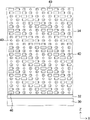
- 1 is a cross-sectional view conceptually showing an example of a liquid crystal diffraction element used as a reflective polarizer;
- FIG. FIG. 18 is a partially enlarged plan view of the liquid crystal diffraction element shown in FIG. 17;
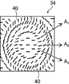
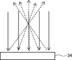
- FIG. 3 is a plan view of a liquid crystal diffraction element; It is a figure for demonstrating the effect
- 1 is a conceptual diagram of an example of an exposure device that exposes an alignment film;
- slow axis means the direction in which the refractive index is maximized within the plane.
- visible light is light with a wavelength that can be seen by the human eye, and indicates light in the wavelength range of 380 to 780 nm, among electromagnetic waves.
- the virtual image display device of the present invention is a transparent display; and an optical system arranged on the viewing side of the transparent display, the optical system includes a half mirror and a reflective polarizer; At least one of the half mirror and the reflective polarizer is a virtual image display device having the action of a concave mirror.
- FIG. 1 is a diagram conceptually showing an example of the virtual image display device of the present invention.
- the virtual image display device 10a shown in FIG. 1 has a transparent display 16, a half mirror 12, and a reflective polarizer 14 in this order.
- Half mirror 12 and reflective polarizer 14 are an optical system in the present invention.
- the side of the transparent display on which the optical system is arranged is called the front side, and the opposite side is called the back side.
- the transparent display 16 is a known transparent display.
- transparent displays include organic electroluminescence display devices, LED (Light Emitting Diode) display devices, micro LED display devices, and other display devices in which self-luminous fine light emitters are arranged on a transparent substrate.
- the transparent display is exemplified by a liquid crystal display configured to transmit light.
- a transparent screen can also be used as the transparent display.
- organic electroluminescent display devices are also referred to as OLEDs.
- OLED is an abbreviation of "Organic Light Emitting Diode”.
- the half mirror 12 and the reflective polarizer 14 are arranged on the visible side of the transparent display 16 .
- the half mirror 12 is a semi-reflective semi-transmissive half mirror that reflects part of the incident light and transmits the rest.
- the reflective polarizer 14 transmits light of one polarization state among incident light, and reflects polarized light orthogonal to this polarized light. That is, the reflective polarizer 14 reflects part of the incident light and transmits the rest.
- the mutually orthogonal polarized light is polarized light positioned on the opposite side of the Poincare sphere, such as the north pole and the south pole of the Poincare sphere.
- the polarized light orthogonal to each other is, for example, right-handed circularly polarized light and left-handed circularly polarized light in the case of circularly polarized light, and linearly polarized light orthogonal to each other in the case of linearly polarized light.
- the reflective polarizer included in the reflective polarizer 14 may be a reflective linear polarizer or a reflective circular polarizer.
- At least one of the half mirror 12 and the reflective polarizer 14 functions as a concave mirror.
- the light emitted from the transparent display 16 passes through the half mirror 12, is then reflected by the reflective polarizer 14, and enters the half mirror 12 again.
- the mirror 12 has a concave incident surface and acts as a concave mirror.
- the configurations of the half mirror 12 and the reflective polarizer 14 will be detailed later.
- FIG. A transparent display 16 illuminates the image. At that time, light is emitted from each point (each pixel) of the transparent display so as to spread in various directions.
- the dashed arrow indicates the light emitted from a certain pixel 16a.
- FIG. 2 the case where the polarization state of the light emitted from the transparent display 16 when it enters the half mirror 12 is right-handed circularly polarized light will be described.
- the light emitted by the transparent display 16 enters the half mirror 12 and is partially transmitted.
- Light transmitted through the half mirror 12 is incident on the reflective polarizer 14 .
- a polarized component of the incident light reflected by the reflective polarizer 14 is reflected by the reflective polarizer 14 and enters the half mirror 12 again.
- reflective polarizer 14 reflects right-handed circularly polarized light.
- the reflective polarizer 14 since the reflective polarizer 14 has the action of a convex mirror, the light is reflected so as to spread further.
- the light reflected by the reflective polarizer 14 enters the half mirror 12 as it is right-handed circularly polarized light.
- a part of the light incident on the half mirror 12 is reflected by the half mirror 12 .
- the half mirror 12 acts as a concave mirror with respect to the incident light, the light is reflected so as to be condensed and directed to the back side of the half mirror 12 (the side opposite to the viewing side). Form a virtual image.
- the circularly polarized light is converted into circularly polarized light in the opposite turning direction by reflection by the half mirror 12 . In the example shown in FIG. 2, the light reflected by the half mirror 12 is converted into left circularly polarized light.
- the light reflected by the half mirror 12 enters the reflective polarizer 14 . Since the light incident on the reflective polarizer 14 is a polarized component (left-handed circularly polarized light) that passes through the reflective polarizer 14 , it passes through the reflective polarizer 14 and the user U is irradiated with the light.
- the light is more concentrated than immediately after being irradiated from the transparent display 16 and emitted to the viewing side.
- the light reflected by the half mirror 12 and the reflective polarizer 14 extends its multiple rays toward the transparent display 16 and appears to be emitted from a certain point O1 where they converge. Therefore, to the user U who sees this light, it appears that the light is emitted from a point O 1 on the far side of the transparent display 16 (the side opposite to the user U side).
- the light emitted from each pixel of the transparent display 16 appears to be emitted from each point behind the transparent display 16 .
- the video (image) displayed by the transparent display 16 is viewed by the user U as a virtual image V 1 behind the transparent display 16 .
- the virtual image display device 10a can display the background and the virtual image (video) in an overlapping manner.
- the virtual image display device 10a has a configuration in which the half mirror 12 and the reflective polarizer 14 are arranged in this order from the transparent display 16 side. 3, the reflective polarizer 14 and the half mirror 12 may be arranged in this order from the transparent display 16 side, as in the virtual image display device 10b shown in FIG.
- a virtual image display device 10b shown in FIG. 3 has a transparent display 16, a reflective polarizer 14, and a half mirror 12 in this order.
- Half mirror 12 and reflective polarizer 14 are an optical system in the present invention.
- the light emitted from the transparent display 16 passes through the reflective polarizer 14, is then reflected by the half mirror 12, and is incident on the reflective polarizer 14 again.
- the reflective polarizer 14 has a concave shape on the incident surface side, and has the action of a concave mirror.
- the light emitted from the transparent display 16 enters the reflective polarizer 14. At that time, light is emitted from each point (each pixel) of the transparent display so as to spread in various directions.
- the dashed arrow indicates the light emitted from a certain pixel 16a.
- Reflective polarizer 14 transmits one polarized component of the incident light. The light transmitted through the reflective polarizer 14 enters the half mirror 12 and is partially reflected. At that time, the polarization state of the light reflected by the half mirror 12 is converted into orthogonal polarized light. In addition, since the half mirror 12 has the action of a convex mirror, the light is reflected so as to spread further.
- the light reflected by the half mirror 12 enters the reflective polarizer 14 again. Since the polarization state of the light is converted by reflection by the half mirror 12 , the light incident on the reflective polarizer 14 is reflected by the reflective polarizer 14 . At that time, since the reflective polarizer 14 has the action of a concave mirror, the light is reflected so as to be condensed.
- the light reflected by the reflective polarizer 14 enters the half mirror 12 . Part of the light that has entered the half mirror 12 is transmitted through the half mirror 12 and illuminates the user U.
- the light is more concentrated than immediately after being irradiated from the transparent display 16 and emitted to the viewing side.
- the light reflected by the half mirror 12 and the reflective polarizer 14 extends its multiple rays toward the transparent display 16 and appears to be emitted from a certain point O1 where they converge. Therefore, to the user U who sees this light, it appears that the light is emitted from a point O 1 on the far side of the transparent display 16 (the side opposite to the user U side).
- the light emitted from each pixel of the transparent display 16 appears to be emitted from each point behind the transparent display 16 .
- the video (image) displayed by the transparent display 16 is viewed by the user U as a virtual image V 1 behind the transparent display 16 .
- the virtual image display device 10a can display the background and the virtual image (video) in an overlapping manner.
- both the half mirror 12 and the reflective polarizer 14 have a concave shape on the user U side, and one of them is a concave mirror with respect to incident light. Although it is said that it has an effect, it is not limited to this.
- the half mirror 12 and/or the reflective polarizer 14 may be formed of a diffraction element or the like to act as a concave mirror for incident light.
- the half mirror 12 and the reflective polarizer 14 the one that does not act as a concave mirror for incident light is flat and does not act as a concave or convex mirror for incident light. There may be.
- a virtual image display device 10c shown in FIG. 4 has a transparent display 16, a reflective polarizer 14c, and a half mirror 12 in this order.
- Half mirror 12 and reflective polarizer 14c are an optical system in the present invention.
- the half mirror 12 has a concave shape on the side of the user U, and acts as a convex mirror on the incident light from the half mirror 12 .
- the reflective polarizer 14c is composed of a diffraction element or the like, and acts as a concave mirror for the light incident on the reflective polarizer 14c after being reflected by the half mirror 12.
- a polarizer 14c A specific configuration of the flat plate-like reflective polarizer 14c that acts as a concave mirror will be described in detail later.
- the virtual image display device 10c shown in FIG. 4 operates in the same manner as the virtual image display device 10b shown in FIG. That is, one of the polarized lights emitted from the transparent display 16 is transmitted through the reflective polarizer 14c, reflected by the half mirror 12, and again enters the reflective polarizer 14c and is reflected. At that time, since the reflective polarizer 14c has the function of a concave mirror, the light is reflected so as to be condensed. The light reflected by the reflective polarizer 14c enters the half mirror 12, a part of which is transmitted, and the user U is irradiated with the light.
- the concave mirror by the reflective polarizer 14c due to the action of the concave mirror by the reflective polarizer 14c, the light is more condensed than immediately after being irradiated from the transparent display 16 and emitted to the viewing side.
- the video (image) displayed by the transparent display 16 is viewed by the user U as a virtual image V 1 behind the transparent display 16 .
- the light R 1 from the background behind the transparent display 16 is transmitted through the transparent display 16, partly transmitted through the reflective polarizer 14c, and further partially transmitted through the half mirror 12 to reach the user U. to reach Thereby, the background is also visually recognized by the user U.
- the virtual image display device 10c can display the background and the virtual image (video) in an overlapping manner.
- the reflective polarizer 14c is composed of a diffraction element or the like to act as a concave mirror. It may be a plate-like half mirror that functions as a concave mirror by being configured.
- the background light incident from the back surface of the transparent display and transmitted through the transparent display is reflected by the half mirror and the reflected light, similarly to the image light emitted by the transparent display.
- the user U may be illuminated through a path that is reflected by the type polarizer. In this case, the background is visually distorted by the user U due to the lens effect.
- the virtual image display device of the present invention at least part of the light beam emitted from the transparent display is in the first polarization state immediately before entering the optical system, enters from the rear surface of the transparent display, and passes through the transparent display.
- at least a portion of the light transmitted through the display is in a second polarization state orthogonal to the first polarization state just prior to entering the optical system.
- the first polarization state may be right-handed circularly polarized light and the second polarization state may be left-handed circularly polarized light, or the first polarization state is left-handed circularly polarized light and the second polarization state is right-handed circularly polarized light There may be.
- the virtual image display device of the present invention further includes a polarization separation element having a function of separating incident light into mutually orthogonal polarized light between the transparent display and the optical system. good too.
- FIG. 5 shows a diagram conceptually showing another example of the virtual image display device of the present invention.
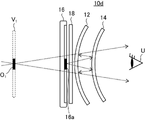
- a virtual image display device 10d shown in FIG. 5 has a transparent display 16, a polarization separating element 18, a half mirror 12, and a reflective polarizer 14 in this order.
- the polarization separation element 18 is an element that separates at least part of the incident light into mutually orthogonal polarized light.
- the mutually orthogonal polarized light is polarized light positioned on the opposite side of the Poincare sphere, such as the north pole and the south pole of the Poincare sphere.
- circularly polarized light is right-handed circularly polarized light and left-handed circularly polarized light
- linearly polarized light is linearly polarized light orthogonal to each other.
- the half mirror 12, the reflective polarizer 14 and the polarization separating element 18 are arranged on the visible side of the transparent display 16.
- Half mirror 12, reflective polarizer 14 and transparent display 16 are as previously described.
- the background light R 1 and the light forming the virtual image V 1 are divided into the optical paths by separating the polarized light by the polarization separation element 18, thereby separating the background and the virtual image V 1 without distortion. Can be displayed overlaid.
- the transparent display 16 may have a pixel area that displays images and a transparent area that does not display images.
- the polarization separation element 18 performs polarization conversion or absorption depending on the position of the incident light, so that the light emitted from the pixel region to form the virtual image V 1 and the background light transmitted through the transparent region are separated from each other. separate the polarizations into mutually orthogonal polarization states. Specifically, the light emitted from the pixel region to form the virtual image V 1 is set in the first polarization state, and the background light passing through the transparent region is set in the second polarization state.
- the transparent display 16 may alternately display image display ON and OFF in a time division manner.
- the polarization splitting element 18 splits the incident light into mutually orthogonal polarized light by temporally alternately performing polarization conversion or absorption on the incident light.
- the image display is ON, the light emitted from the transparent display 16 to form the virtual image V1 is set to be in the first polarization state, and when the image display is OFF, the transparent display 16 is turned on. Allow the transmitted background light to be in the second polarization state.
- the polarization separating element 18 converts the light emitted from the transparent display 16 and forming the virtual image V 1 into polarized light reflected by the reflective polarizer 14 . Therefore, the light converted by the polarization separating element 18 is reflected between the reflective polarizer 14 and the half mirror 12, makes one round trip, and is emitted to the viewing side.
- the polarization separation element 18 converts the background light that has passed through the transparent display 16 into polarized light that passes through the reflective polarizer 14 .
- the light converted by the polarization separating element 18 is transmitted through the half mirror 12 and the reflective polarizer 14 without being reflected by the half mirror 12 and the reflective polarizer 14, and is emitted to the viewing side.
- the background light transmitted through the transparent display 16 exists at the same time and may overlap.
- a light-shielding element capable of switching between a light-shielding state and a light-transmitting state may be arranged on the back side of the transparent display 16 so that the background light is not transmitted when the image display is ON.
- a liquid crystal cell, an electrochromic element, or the like can be used as the light shielding element.
- the polarization separation element 18 converts incident light into polarized light that passes through the reflective polarizer 14. do. Therefore, the light converted by the polarization separating element 18 is transmitted through the half mirror 12 and the reflective polarizer 14 without being reflected by the half mirror 12 and the reflective polarizer 14, and is emitted to the viewing side.
- the polarization separation element 18 converts incident light into polarized light reflected by the reflective polarizer 14 . Therefore, the light converted by the polarization separating element 18 is reflected between the reflective polarizer 14 and the half mirror 12, makes one round trip, and is emitted to the viewing side.
- the virtual image display device 10d can display the distortion - free background and the virtual image V1 in a superimposed manner by dividing the optical paths of the background light R1 and the light forming the virtual image V1.
- the polarization separation element 18, the half mirror 12, and the reflective polarizer 14 are arranged in this order from the transparent display 16 side, but this is not limiting. Instead, the reflective polarizer 14, the half mirror 12, and the polarization separation element 18 may be arranged in this order from the transparent display 16 side.
- both the light that forms the virtual image V 1 and the background light are preferably in a polarized state that passes through the reflective polarizer 14 immediately before entering the optical system. At this time, the light that forms the virtual image V 1 and the background light are respectively reflected between the reflective polarizer 14 and the half mirror 12, make one round trip, and are emitted to the viewing side in the first polarized state.
- the reflective polarizer 14 will be described as a reflective circular polarizer that reflects right-handed circularly polarized light and transmits left-handed circularly polarized light.
- the transparent display 16 has a linear polarizer on its surface, and the light emitted from the transparent display 16 and the light transmitted through the transparent display 16 are linearly polarized light. I do.
- the polarization separation element 18 is a retardation layer, and is an active retardation layer capable of switching the direction of the slow axis or the magnitude of retardation when performing time-division display, When spatially divided display is performed, the patterned retardation layer has a plurality of regions with different slow axis directions or different retardation magnitudes.
- the polarization separation element 18 will be detailed later.
- FIG. 6 shows the timing of displaying the virtual image V 1 or the state of the area displaying the virtual image V 1 in the virtual image display device 10d. The operation of the virtual image display device 10d in this state will be described.
- the transparent display 16 emits light that becomes an image (virtual image). At that time, as described above, the light is emitted from each point (each pixel) of the transparent display so as to spread in various directions. As an example, the light emitted by the transparent display 16 is emitted as linearly polarized light in the vertical direction in the figure. The linearly polarized light irradiated by the transparent display 16 is transmitted through the polarization separation element 18 and converted into circularly polarized light.
- the polarization separation element 18 is a retardation layer, and the polarization separation element 18 converts vertically linearly polarized light into right-handed circularly polarized light.
- this right-handed circularly polarized light enters the half mirror 12
- part of the light is reflected and converted into left-handed circularly polarized light.
- the reflected light enters the polarization separation element 18 and is polarized in a direction orthogonal to the linearly polarized light in the vertical direction (direction perpendicular to the paper surface; in the following description, it is also referred to as linearly polarized light in the horizontal direction. ) is converted into linearly polarized light (not shown).
- This linearly polarized light enters the transparent display 16 and is absorbed by the linear polarizer that the transparent display 16 has.
- the remaining right-handed circularly polarized light incident on the half mirror 12 passes through the half mirror 12 and enters the reflective polarizer 14 .
- the reflective polarizer 14 reflects right-handed circularly polarized light.
- the left-handed circularly polarized light reflected by the half mirror 12 enters the reflective polarizer 14 . Since the reflective polarizer 14 reflects right-handed circularly polarized light, left-handed circularly polarized light is transmitted and reaches the user U.
- the transparent display 16 displays the virtual image V 1 or in the area where the virtual image V 1 is displayed
- the light passing through the optical path that becomes the virtual image V 1 is reflected by the reflective polarizer.
- the light is reflected between 14 and the half mirror 12, goes back and forth, and is emitted to the user U side.
- the image displayed by the transparent display 16 is visually recognized by the user U as a virtual image V 1 behind the transparent display.
- FIG. 7 shows the timing of displaying the background or the state of the area where the background is displayed in the virtual image display device 10d. The operation of the virtual image display device 10d in this state will be described.
- Background light R 1 is transmitted through the transparent display 16 .
- the transparent display since the transparent display has a linear polarizer, the light transmitted through the transparent display 16 is converted into vertically linearly polarized light.
- This linearly polarized light is transmitted through the polarization separating element 18, which is a retardation layer, and converted into circularly polarized light.
- the polarization separation element 18 converts vertically linearly polarized light into left-handed circularly polarized light. That is, in FIGS. 6 and 7, the polarization separation element 18 is an active retardation layer or a patterned retardation layer, and in the state shown in FIG. The direction of the slow axis is different from that in the state shown in FIG. 6, and the vertical linearly polarized light transmitted through the polarization separation element 18 (retardation layer) is converted into left-handed circularly polarized light, which is the opposite of the state shown in FIG. .
- this left-handed circularly polarized light enters the half mirror 12
- part of the light is reflected and converted into right-handed circularly polarized light (not shown).
- the reflected light enters the polarization separation element 18 and is converted into linearly polarized light in the left-right direction (perpendicular to the plane of the paper).
- This linearly polarized light enters the transparent display 16 and is absorbed by the linear polarizer that the transparent display 16 has.
- the remaining left-handed circularly polarized light incident on the half mirror 12 passes through the half mirror 12 and is incident on the reflective polarizer 14 . Since it is circularly polarized light, it passes through the reflective polarizer 14 and reaches the user U.
- the background light passes through only the optical path through which all the members of the virtual image display device 10d are transmitted, The light is irradiated to the side and is prevented from passing through the optical path that is reflected within the virtual image display device 10d. This can prevent the background from being distorted and visually recognized.
- the polarization separation element 18 passes the optical path through which all the members of the virtual image display device 10d transmit the background light.
- the polarizing beam splitter 18 causes the image light to become the virtual image V 1 , that is, the reflective polarizer 14 and the half mirror 12 .
- a virtual image V 1 is displayed by passing an optical path that makes one round trip between them.
- the virtual image display device 10d can display the background and the virtual image V 1 in a time-division or space-division manner so that the background and the virtual image V 1 overlap each other.
- the polarization separation element 18 has been described as an active retardation layer or a patterned retardation layer, but it is not limited to this.
- the polarization splitting element 18 is a linear polarizer, an active polarizer capable of switching the direction of the transmission axis or the absorption axis, or a patterned polarizer having a plurality of two regions with different directions of the transmission axis or the absorption axis. There may be.
- the transparent display 16 When the polarization separation element 18 is an active polarizer or a patterned polarizer, a normal retardation layer is placed between the polarization separation element 18 and the optical system, and the transparent display 16 has a linear polarizer.
- a configuration that does not With such a configuration at the timing or in the area where the virtual image V 1 is displayed, the light of the image irradiated by the transparent display 16 is converted into one linearly polarized light by the polarization separation element 18, and is converted into one linearly polarized light by the retardation layer. It is converted into circularly polarized light and enters the optical system.
- the background light is transmitted through the transparent display 16, converted into the other linearly polarized light by the polarization separation element 18, and converted into the other circularly polarized light by the retardation layer. incident on the optical system.
- the optical path when passing through the optical system becomes the same optical path as in FIGS. 6 and 7 described above. Therefore, even when an active polarizer or a patterned polarizer is used as the polarization separation element 18, the virtual image display device displays the background and the virtual image V1 in a time-division or space-division manner. V 1 can be superimposed and displayed.
- the polarization separation element 18 is arranged between the transparent display 16 and the optical system, but the configuration is not limited to this.
- the polarization separation element 18 may be arranged between the half mirror 12 and the reflective polarizer 14, or may be arranged on the viewing side of the optical system.
- the reflective polarizer 14 may be a reflective linear polarizer that transmits linearly polarized light in a certain direction and reflects linearly polarized light in a direction perpendicular to the linearly polarized light. It may be a reflective circular polarizer that transmits polarized light and reflects circularly polarized light whose direction of rotation is opposite to that of the transmitted circularly polarized light.
- the optical system includes at least a half mirror, a ⁇ /4 retardation layer, a reflective linear polarizer, and an absorbing linear polarizer in this order. It is preferable to have
- FIG. 8 shows a diagram conceptually showing another example of the virtual image display device of the present invention.
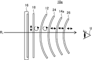
- a virtual image display device 10e shown in FIG. in that order.
- the half mirror 12, the ⁇ /4 retardation layer 24, the reflective linear polarizer 14a, and the absorbing linear polarizer 26 constitute an optical system in the present invention.
- the ⁇ /4 retardation layer 24 is a known retardation layer having a ⁇ /4 retardation.
- the ⁇ /4 retardation layer 24 converts incident linearly polarized light into circularly polarized light, or converts circularly polarized light into linearly polarized light.
- the absorptive linear polarizer 26 is a known absorptive linear polarizer.
- FIG. 8 The operation of the virtual image display device 10e shown in FIG. 8 will be described using FIGS. 9 and 10.
- FIG. 9 The operation of the virtual image display device 10e shown in FIG. 8 will be described using FIGS. 9 and 10.
- FIG. 9 shows the timing of displaying the virtual image V 1 or the state of the area displaying the virtual image V 1 in the virtual image display device 10e.
- the operation of the virtual image display device 10e in this state will be described. Although illustration is omitted, it is assumed that the transparent display 16 has a linear polarizer and the polarization separation element 18 is a patterned retardation layer or an active retardation layer.
- the transparent display 16 emits light that becomes an image (virtual image). At that time, as described above, the light is emitted from each point (each pixel) of the transparent display so as to spread in various directions. As an example, the light emitted by the transparent display 16 is emitted as linearly polarized light in the vertical direction in the figure. The linearly polarized light irradiated by the transparent display 16 is transmitted through the polarization separation element 18 and converted into circularly polarized light.
- the polarization separation element 18 is a retardation layer, and the polarization separation element 18 converts vertically linearly polarized light into right-handed circularly polarized light.
- this right-handed circularly polarized light enters the half mirror 12
- part of the light is reflected and converted into left-handed circularly polarized light.
- the reflected light enters the polarization separation element 18 and is converted into linearly polarized light in the left-right direction (perpendicular to the plane of the paper) (not shown).
- This linearly polarized light enters the transparent display 16 and is absorbed by the linear polarizer that the transparent display 16 has.
- the remaining right-handed circularly polarized light incident on the half mirror 12 is transmitted through the half mirror 12 and then through the ⁇ /4 retardation layer 24 . At that time, the light is converted into linearly polarized light by the ⁇ /4 retardation layer 24 .
- the ⁇ /4 retardation layer 24 converts right-handed circularly polarized light into vertically linearly polarized light.
- the linearly polarized light that has passed through the ⁇ /4 retardation layer 24 is incident on the reflective linear polarizer 14a.
- the reflective linear polarizer 14a since the reflective linear polarizer 14a reflects linearly polarized light in the vertical direction, the linearly polarized light incident on the reflective linear polarizer 14a is reflected and enters the ⁇ /4 retardation layer 24. .
- the ⁇ /4 retardation layer 24 converts incident linearly polarized light in the vertical direction into right circularly polarized light.
- This right-handed circularly polarized light enters the half mirror 12 and is partially reflected. Right-handed circularly polarized light is then converted into left-handed circularly polarized light by reflection. Moreover, since the half mirror 12 has the function of a concave mirror, it reflects the light so as to converge. On the other hand, the remaining right-handed circularly polarized light incident on the half mirror 12 is transmitted through the half mirror 12 . The right-handed circularly polarized light transmitted through the half mirror 12 is converted into vertical linearly polarized light by the polarization separation element 18 . This linearly polarized light passes through the linear polarizer of the transparent display 16 and passes through the transparent display 16 .
- the left-handed circularly polarized light reflected by the half mirror 12 enters the ⁇ /4 retardation layer 24 and is converted into linearly polarized light in the left-right direction. Since this linearly polarized light is linearly polarized in a direction orthogonal to the linearly polarized light reflected by the reflective linear polarizer 14a, it is transmitted through the reflective linear polarizer 14a.
- the linearly polarized light that has passed through the reflective linear polarizer 14 a enters the absorbing linear polarizer 26 .
- the absorbing linear polarizer 26 transmits linearly polarized light in the same direction as the linearly polarized light transmitted by the reflective linear polarizer 14a. Therefore, in the illustrated example, the absorbing linear polarizer 26 transmits linearly polarized light in the horizontal direction in the figure. Therefore, the left-right linearly polarized light reaches the user U through the absorbing linear polarizer 26 .
- the light that becomes the virtual image V1 is directed to the reflective linear polarizer 14a and the The light passes through the optical path that makes one round trip between the half mirrors 12 and is emitted to the user U side.
- the image displayed by the transparent display 16 is visually recognized by the user U as a virtual image V 1 behind the transparent display.
- FIG. 10 shows the timing of displaying the background or the state of the area where the background is displayed in the virtual image display device 10e. The operation of the virtual image display device 10e in this state will be described.
- Background light R 1 is transmitted through the transparent display 16 .
- the transparent display since the transparent display has a linear polarizer, the light transmitted through the transparent display 16 is converted into vertically linearly polarized light.
- This linearly polarized light is transmitted through the polarization separating element 18, which is a retardation layer, and converted into circularly polarized light.
- the polarization separation element 18 converts vertically linearly polarized light into left-handed circularly polarized light. That is, in FIGS. 9 and 10, the polarization separation element 18 is an active phase difference layer or a patterned phase difference layer, and in the state shown in FIG. The directions of the axes are different, and the vertical linearly polarized light transmitted through the polarization separation element 18 is converted into left-handed circularly polarized light, which is the opposite of the state shown in FIG.
- this left-handed circularly polarized light enters the half mirror 12
- part of the light is reflected and converted into right-handed circularly polarized light (not shown).
- the reflected light enters the polarization separation element 18 and is converted into linearly polarized light in the left-right direction (perpendicular to the plane of the paper).
- This linearly polarized light enters the transparent display 16 and is absorbed by the linear polarizer that the transparent display 16 has.
- the remaining left-handed circularly polarized light incident on the half mirror 12 is transmitted through the half mirror 12 and then through the ⁇ /4 retardation layer 24 . At that time, the light is converted into linearly polarized light by the ⁇ /4 retardation layer 24 .
- the ⁇ /4 retardation layer 24 converts right-handed circularly polarized light into vertical linearly-polarized light, so that left-handed circularly polarized light is converted into horizontal linearly-polarized light.
- the left-right linearly polarized light converted by the ⁇ /4 retardation layer 24 is incident on the reflective linear polarizer 14a. , passes through the reflective linear polarizer 14a.
- the linearly polarized light that has passed through the reflective linear polarizer 14a passes through the absorptive linear polarizer 26 and reaches the user U.
- the background light is emitted to the user U side through the optical path passing through all the members of the virtual image display device 10e. do. This can prevent the background from being distorted and visually recognized.
- the polarization separation element 18 passes the optical path through which the background light is transmitted through all the members of the virtual image display device 10e. In this manner, the background is made visible, and at the timing or in the region where the transparent display 16 displays the virtual image V 1 , the polarization separation element 18 causes the light that becomes the virtual image V 1 to pass through the reflective linear polarizer 14 a and the half mirror. A virtual image V 1 is displayed through an optical path that makes one round trip between 12 .
- the virtual image display device 10e can display the background and the virtual image V1 in a time - division or space-division manner, thereby overlapping the background and the virtual image V1.
- the virtual image display device 10e preferably has an absorptive linear polarizer 26 on the viewing side of the reflective linear polarizer 14a.
- the absorptive linear polarizer 26 By having the absorptive linear polarizer 26, stray light such as a linearly polarized component in the vertical direction that has not been reflected by the reflective linear polarizer 14a can be absorbed by the absorptive linear polarizer 26, resulting in stray light. It is possible to more reliably prevent unnecessary images from being viewed. In addition, it is possible to prevent external light from being reflected on the surface of the virtual image display device 10e and causing so-called glare.
- the transmission axis of the reflective linear polarizer 14a and the transmission axis of the absorbing linear polarizer 26 are parallel. Furthermore, at the timing of displaying the virtual image V 1 or in the state of the area displaying the virtual image V 1 , the slow axis of the retardation layer that is the polarization separation element 18 and the slow axis of the ⁇ /4 retardation layer 24 are , are preferably orthogonal to each other. Further, it is preferable that the retardation layer which is the polarization separation element 18 and the ⁇ /4 retardation layer 24 have the same retardation.
- the wavelength dispersion properties are the same, and it is more preferable that both have reverse dispersion properties.
- the above configuration is preferable because stray light such as linearly polarized light components that are not reflected by the reflective linear polarizer 14a can be further reduced.
- the optical system includes at least a half mirror, a reflective circular polarizer, a ⁇ /4 retardation layer, and an absorbing linear polarizer in this order. It is preferable to have
- FIG. 11 shows a diagram conceptually showing another example of the virtual image display device of the present invention.
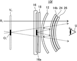
- a virtual image display device 10f shown in FIG. in that order.
- the half mirror 12, the reflective circular polarizer 14b, the ⁇ /4 retardation layer 24, and the absorbing linear polarizer 26 constitute an optical system in the present invention.
- FIG. 11 The action of the virtual image display device 10f shown in FIG. 11 will be explained using FIGS. 12 and 13.
- FIG. 12 The action of the virtual image display device 10f shown in FIG. 11 will be explained using FIGS. 12 and 13.
- FIG. 12 The action of the virtual image display device 10f shown in FIG. 11 will be explained using FIGS. 12 and 13.
- FIG. 12 shows the timing of displaying the virtual image V 1 or the state of the area displaying the virtual image V 1 in the virtual image display device 10f.
- the operation of the virtual image display device 10f in this state will be described. Although illustration is omitted, it is assumed that the transparent display 16 has a linear polarizer and the polarization separation element 18 is a patterned retardation layer or an active retardation layer.
- the transparent display 16 emits light that becomes an image (virtual image). At that time, as described above, the light is emitted from each point (each pixel) of the transparent display so as to spread in various directions. As an example, the light emitted by the transparent display 16 is emitted as linearly polarized light in the vertical direction in the figure. The linearly polarized light irradiated by the transparent display 16 is transmitted through the polarization separation element 18 and converted into circularly polarized light.
- the polarization separation element 18 is a retardation layer, and the polarization separation element 18 converts vertically linearly polarized light into right-handed circularly polarized light.
- this right-handed circularly polarized light enters the half mirror 12
- part of the light is reflected and converted into left-handed circularly polarized light.
- the reflected light enters the polarization separation element 18 and is converted into linearly polarized light in the horizontal direction (the direction perpendicular to the plane of the paper) (not shown).
- This linearly polarized light enters the transparent display 16 and is absorbed by the linear polarizer that the transparent display 16 has.
- the remaining right-handed circularly polarized light incident on the half mirror 12 passes through the half mirror 12 and enters the reflective circular polarizer 14b.
- the reflective circular polarizer 14 b reflects right-handed circularly polarized light.
- the left-handed circularly polarized light reflected by the half mirror 12 enters the reflective circular polarizer 14b. Since the reflective circular polarizer 14b reflects right-handed circularly polarized light, it transmits left-handed circularly polarized light.
- the incident left-handed circularly polarized light is converted into linearly polarized light by the ⁇ /4 retardation layer 24 .
- the ⁇ /4 retardation layer 24 converts left-handed circularly polarized light into left-right linearly polarized light.
- the linearly polarized light that has passed through the ⁇ /4 retardation layer 24 enters the absorbing linear polarizer 26 .
- the absorbing linear polarizer 26 transmits linearly polarized light in the same direction as the linearly polarized light that is converted by the ⁇ /4 retardation layer 24 from the linearly polarized light transmitted by the reflective circular polarizer 14b. Therefore, in the illustrated example, the absorbing linear polarizer 26 transmits linearly polarized light in the horizontal direction in the figure. Therefore, the linearly polarized light in the left-right direction is transmitted through the absorbing linear polarizer 26 and reaches the user U.
- the light that becomes the virtual image V 1 is directed to the reflective circular polarizer 14b and The light passes through the optical path that makes one round trip between the half mirrors 12 and is emitted to the user U side.
- the image displayed by the transparent display 16 is visually recognized by the user U as a virtual image V 1 behind the transparent display.
- FIG. 13 shows the timing of displaying the background or the state of the area where the background is displayed in the virtual image display device 10f. The operation of the virtual image display device 10f in this state will be described.
- Background light R 1 is transmitted through the transparent display 16 .
- the transparent display since the transparent display has a linear polarizer, the light transmitted through the transparent display 16 is converted into vertical linearly polarized light.
- This linearly polarized light is transmitted through the polarization separating element 18, which is a retardation layer, and converted into circularly polarized light.
- the polarization separation element 18 converts vertically linearly polarized light into left-handed circularly polarized light. That is, in FIGS. 12 and 13, the polarization separation element 18 is an active retardation layer or a patterned retardation layer, and in the state shown in FIG. The directions of the axes are different, and the vertical linearly polarized light transmitted through the polarization separation element 18 is converted into left-handed circularly polarized light, which is the opposite of the state shown in FIG.
- this left-handed circularly polarized light enters the half mirror 12
- part of the light is reflected and converted into right-handed circularly polarized light (not shown).
- the reflected light enters the polarization separation element 18 and is converted into linearly polarized light in the left-right direction (perpendicular to the plane of the paper).
- This linearly polarized light enters the transparent display 16 and is absorbed by the linear polarizer that the transparent display 16 has.
- the remaining left-handed circularly polarized light incident on the half mirror 12 passes through the half mirror 12 and enters the reflective circular polarizer 14b. Therefore, it is transmitted through the reflective circular polarizer 14b.
- the ⁇ /4 retardation layer 24 converts left-handed circularly polarized light into left-right linearly polarized light.
- the left-right linearly polarized light converted by the ⁇ /4 retardation layer 24 enters the absorbing linear polarizer 26 .
- the absorptive linear polarizer 26 transmits linearly polarized light in the left-right direction in the drawing, so the linearly polarized light in the left-right direction is transmitted through the absorptive linear polarizer 26 and reaches the user U.
- the light of the background passes through the optical path that passes through all the members of the virtual image display device 10f, and the user U This prevents the background from being distorted and visually recognized.
- the polarization separation element 18 passes the optical path through which the background light is transmitted through all the members of the virtual image display device 10f. In this manner, the background is made visible, and at the timing or in the region where the transparent display 16 displays the virtual image V1, the polarization separating element 18 causes the light that becomes the virtual image V1 to be reflected by the reflective circular polarizer 14b and the half mirror.
- a virtual image V 1 is displayed through an optical path that makes one round trip between 12 .
- the virtual image display device 10f can display the background and the virtual image V1 in a time - division or space-division manner, thereby overlapping the background and the virtual image V1.
- the virtual image display device 10f has, as a preferred embodiment, a ⁇ /4 retardation layer 24 and an absorption linear polarizer 26 on the viewing side of the reflective circular polarizer 14b.
- the ⁇ /4 retardation layer 24 and the linear absorbing polarizer 26 act as an absorbing circular polarizer.
- stray light such as a right-handed circularly polarized component that has not been reflected by the reflective circular polarizer 14b can be absorbed by the absorptive circular polarizer, and an unnecessary image caused by the stray light can be eliminated. Visibility can be suppressed more reliably.
- various retardation layers (including retardation layers as polarization splitting elements) have reverse dispersion.
- the retardation layer has reverse dispersion, light incident on the reflective circular polarizer becomes more ideal circularly polarized light, and stray light can be further reduced, which is preferable.
- a combination of a transparent screen having a cholesteric liquid crystal layer and a projector may be used as the transparent display.
- the image projected onto the transparent screen from the projector can be used as the image forming the virtual image V1.
- the cholesteric liquid crystal layer reflects only right-handed circularly polarized light or left-handed circularly polarized light depending on the direction (sense) of helical rotation by the liquid crystal compound, so this can be used as the first polarization state.
- the background light incident from the background side of the transparent screen having the cholesteric liquid crystal layer is in the second polarization state orthogonal to the first polarization state.
- a transparent screen having a cholesteric liquid crystal layer when used as a transparent display, at least part of the light beam forming the virtual image V1 is in the first polarization state immediately before entering the optical system. , at least a portion of a light ray incident from the back of the transparent display and transmitted through the transparent display is in a second polarization state orthogonal to the first polarization state immediately before entering the optical system. .
- a transparent screen with a cholesteric liquid crystal layer will be described in detail later.
- the virtual image display device of the present invention may have an infrared illumination device on the back side of the transparent display, and the infrared illumination device may be configured to illuminate the user's eyes through the optical system.
- the virtual image display device of the present invention has an infrared sensor on the back side of the transparent display, The infrared sensor may be configured to photograph the user's eyes through the optical system.
- FIG. 14 conceptually shows another example of the virtual image display device of the present invention.
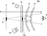
- a virtual image display device 10g shown in FIG. 14 has a transparent display 16 and an optical system having a half mirror 12 and a reflective polarizer 14 in this order.
- An infrared lighting device 50 and an infrared sensor 52 are provided on the side opposite to the side to be exposed.
- a virtual image display device 10g shown in FIG. 14 has an optical system similar to that of the virtual image display device 10a shown in FIG. Therefore, the virtual image display device 10g can display the background and the virtual image V 1 in an overlapping manner by the same action as the virtual image display device 10a.
- the infrared lighting device 50 is arranged to irradiate infrared light toward the transparent display 16 side, and irradiates the infrared light toward the eyes of the user U through the optical system.
- the infrared illumination device 50 conventionally known infrared light sources that irradiate infrared rays can be appropriately used.
- the infrared light source known LEDs (light-emitting diodes), organic light-emitting diodes (OLEDs), infrared lasers, VCSELs (vertical cavity surface emitting semiconductor lasers), glow bars, xenon lamps, halogen lamps, and the like can be used.
- LEDs light-emitting diodes
- OLEDs organic light-emitting diodes
- VCSELs vertical cavity surface emitting semiconductor lasers
- glow bars xenon lamps, halogen lamps, and the like.
- xenon lamps halogen lamps, and the like
- the infrared sensor 52 is arranged with its light-receiving surface facing the transparent display 16 side, and photographs the eyes of the user U through the optical system. That is, the infrared sensor 52 detects infrared light reflected by the user's eye and/or the periphery of the eye.
- the infrared sensor 52 a combination of a photoelectric conversion element such as a CCD sensor or a CMOS sensor and an infrared light filter that allows infrared light to pass through, an infrared camera, or the like can be used.
- a photoelectric conversion element such as a CCD sensor or a CMOS sensor
- an infrared light filter that allows infrared light to pass through, an infrared camera, or the like
- the virtual image display device 10g has an infrared lighting device 50 and an infrared sensor 52, and emits infrared light emitted by the infrared lighting device 50 and reflected by the eye and/or the periphery of the eye of the user U. Detected by the sensor 52 .
- the line-of-sight direction of the user U can be detected from the amount of infrared light detected by the infrared sensor 52, the image captured with the infrared light, and the like.
- a method of detecting (calculating) the line-of-sight direction of the user U using infrared light a conventionally known method may be used.
- the virtual image display device 10g By detecting the line-of-sight direction of the user U of the virtual image display device 10g using infrared light, it is possible to focus on what the user U is looking at or increase the resolution of the area the user U is looking at. For example, it can be used to improve the performance of the virtual image display device.
- infrared lighting devices 50 and/or infrared sensors 52 may be provided.
- a half mirror is a conventionally known half mirror that transmits approximately half of incident light and reflects the remaining approximately half.
- the transmittance of the half mirror is preferably 50 ⁇ 30%, more preferably 50 ⁇ 10%, most preferably 50%.
- the half mirror is made of a transparent resin such as polyethylene terephthalate (PET), cycloolefin polymer (COP), polymethyl methacrylate (PMMA), or a substrate made of glass or the like, and a metal such as silver or aluminum is coated on the substrate. and the like.
- a reflective layer made of metal such as silver or aluminum is formed on the surface of the substrate by vapor deposition or the like.
- the thickness of the reflective layer is preferably 1 to 20 nm, more preferably 2 to 10 nm, even more preferably 3 to 6 nm.
- the base material does not have retardation.
- the half mirror 12 itself may be formed in a concave shape as in the example shown in FIG.
- the half mirror 12 may be a plate-like one that functions as a concave mirror by being composed of a diffraction element or the like.
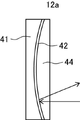
- the half mirror 12a shown in FIG. 15 includes a transparent support 41 having a concave surface, a reflective surface 42 formed on the concave surface of the support 41, and a surface of the reflective surface 42 opposite to the support 41. It has a cover layer 44 .
- the support 41 is made of transparent resin such as polyethylene terephthalate (PET), cycloolefin polymer (COP), polymethyl methacrylate (PMMA), glass, or the like. It has a recessed portion of the paraboloid.
- the material of the reflective surface 42, the forming method, and the like are the same as those of the reflective surface of a general half mirror.
- the reflecting surface 42 can be formed on the concave surface of the support 41 by vapor deposition of metal such as silver or aluminum.
- the thickness is preferably 1 to 20 nm, more preferably 2 to 10 nm, even more preferably 3 to 6 nm.
- the support 41 does not have a retardation.
- the half mirror 12a semi-transmits and semi-reflects incident light, and has the function of a concave mirror that collects the reflected light by forming the reflecting surface 42 in a concave shape.
- the half mirror 12a of the illustrated example has, as a preferred embodiment, a covering layer 44 laminated on the surface of the reflecting surface 42 opposite to the support 41 .
- the covering layer 44 is preferably transparent. Moreover, it is preferably made of a material having substantially the same refractive index as that of the support 41 . Moreover, it is preferable that the coating layer 44 does not have a retardation.
- the surface of the support 41 opposite to the reflecting surface 42 and the surface of the coating layer 44 opposite to the reflecting surface 42 are preferably flat surfaces parallel to each other.
- the half mirror 12a has a coating layer 44 having substantially the same refractive index as the support 41, and the surfaces of the support 41 and the coating layer 44 are flat surfaces parallel to each other.
- the transmitted light can be prevented from being bent by the concave surface of the support 41, and the image of the light transmitted through the half mirror 12a can be prevented from being enlarged or reduced.
- the refractive index of the support 41 and the refractive index of the coating layer 44 do not have to be exactly the same as long as the above effects can be obtained, and they may differ within the range in which the effects are exhibited.
- the difference between the refractive index of the support 41 and the coating layer 44 is preferably 0.1 or less, more preferably 0.05 or less, and even more preferably 0.01 or less.
- FIG. 16 is a cross-sectional view showing an example of a half mirror of a Fresnel mirror.
- the half mirror 12c shown in FIG. It has a coating layer 44 laminated on the opposite side.
- the support 41 is made of transparent resin such as polyethylene terephthalate (PET), cycloolefin polymer (COP), polymethyl methacrylate (PMMA), or glass, and has a well-known Fresnel lens shape on one surface.
- the material of the reflecting surface 42, the forming method, and the like are the same as those of a general half-mirror reflecting surface.
- the reflective surface 42 can be formed on the surface of the support 41 on which Fresnel lens-shaped grooves are formed by vapor deposition of metal such as silver or aluminum.
- the thickness is preferably 1 to 20 nm, more preferably 2 to 10 nm, even more preferably 3 to 6 nm.
- the half mirror 12c semi-transmits and semi-reflects the incident light, and has the function of a concave mirror that collects the reflected light by the same function as a concave mirror because the reflecting surface 42 is formed in the shape of a Fresnel mirror. .
- the half mirror 12c of the illustrated example also has a coating layer 44 laminated on the surface of the reflecting surface 42 opposite to the support 41 as a preferred embodiment.
- the coating layer is preferably transparent, and the difference between the refractive index of the support 41 and the coating layer 44 is preferably 0.1 or less, more preferably 0.05 or less, and further preferably 0.01 or less. preferable. Moreover, it is preferable that the coating layer 44 does not have a retardation.
- the reflective polarizer has a reflective polarizer, which constitutes the reflective surface of the reflective polarizer, and transmits light in one polarization state of the incident light. It reflects polarized light orthogonal to the polarized light.
- a reflective polarizer is basically a reflective linear polarizer or a reflective circular polarizer.
- a reflective linear polarizer is a polarizer that transmits linearly polarized light in a certain direction and reflects linearly polarized light in a direction perpendicular to the linearly polarized light.
- the reflective linear polarizer include films obtained by stretching a dielectric multilayer film, as described in JP-A-2011-053705, etc., A wire grid type polarizer and the like are exemplified.
- Commercially available reflective linear polarizers are also suitable for use.
- Commercially available reflective linear polarizers include reflective polarizers (trade name: APF) manufactured by 3M and wire grid polarizers (trade name: WGF) manufactured by AGC.
- a reflective circular polarizer is a polarizer that transmits right-handed circularly polarized light or left-handed circularly polarized light and reflects circularly polarized light whose direction of rotation is opposite to that of the transmitted circularly polarized light.
- a reflective circular polarizer having a cholesteric liquid crystal layer is exemplified.
- a cholesteric liquid crystal layer is a liquid crystal phase obtained by fixing a cholesterically aligned liquid crystal phase (cholesteric liquid crystal phase).
- a cholesteric liquid crystal layer has a helical structure in which a liquid crystal compound is spirally revolved and stacked.
- a cycle helical cycle
- a liquid crystal compound that spirals spirally has a structure in which multiple cycles are stacked.
- the cholesteric liquid crystal layer reflects right-handed or left-handed circularly polarized light in a specific wavelength range and transmits other light, depending on the length of the helical period and the direction of helical rotation (sense) of the liquid crystal compound. do.
- the reflective circular polarizer may include, for example, a cholesteric liquid crystal layer having a central wavelength of selective reflection to red light, a central wavelength of selective reflection to green light, and a cholesteric liquid crystal layer having a central wavelength of selective reflection for blue light.
- the reflective circular polarizer when it has a cholesteric liquid crystal layer, it may have a support and an alignment film for orienting the liquid crystal compound in the cholesteric liquid crystal layer.
- the thickness of the reflective polarizer is determined according to the type of the reflective polarizer so that the polarized light that should be reflected can be sufficiently reflected and the polarized light that should be transmitted can be sufficiently transmitted. It can be adjusted as appropriate.
- the reflective polarizer 14 itself may be formed in a concave shape, as in the example shown in FIG.
- the reflective polarizer 14 may be a plate-like one that functions as a concave mirror by being composed of a diffraction element or the like.
- Examples of the flat reflective polarizer 14 include the various half mirrors shown in FIGS. 15 and 16 in which the reflective surface 42 is replaced with the above-described reflective linear polarizer or reflective circular polarizer layer. .
- the reflective polarizer is a cholesteric liquid crystal layer having a radial liquid crystal alignment pattern in which the direction of the optic axis derived from the liquid crystal compound is continuously rotated along one in-plane direction on either surface. It may be a liquid crystal diffraction element containing.
- FIG. 17 to 19 are diagrams for explaining the liquid crystal diffraction element (cholesteric liquid crystal layer) of the reflective polarizer.
- FIG. 17 is a cross-sectional view conceptually showing a liquid crystal diffraction element.
- 18 is a plan view of the liquid crystal diffraction element (cholesteric liquid crystal layer) shown in FIG. 17.
- FIG. 19 is a plan view for explaining the configuration of the liquid crystal diffraction element.
- the liquid crystal diffraction element shown in FIGS. 17 and 18 has a fixed cholesteric liquid crystal phase, and the orientation of the optic axis derived from the liquid crystal compound changes while continuously rotating along one direction within the plane. It has a patterned cholesteric liquid crystal layer 34 .
- the liquid crystal diffraction element has a support 30, an alignment film 32, and a cholesteric liquid crystal layer .
- the liquid crystal diffraction element of the example shown in FIG. 17 has a support 30, an alignment film 32, and a cholesteric liquid crystal layer 34
- the present invention is not limited to this.
- the liquid crystal diffraction element may have, for example, only the alignment film 32 and the cholesteric liquid crystal layer 34 from which the support 30 is removed.
- the liquid crystal diffraction element may have only the cholesteric liquid crystal layer 34 from which the support 30 and the alignment film 32 are removed, for example.
- the cholesteric liquid crystal layer 34 is a cholesteric liquid crystal layer in which the cholesteric liquid crystal phase is fixed.
- a cholesteric liquid crystal layer having a liquid crystal orientation pattern in which the direction of the optic axis derived from the liquid crystal compound changes while continuously rotating along one direction in the plane on any surface is provided on the main surface of the cholesteric liquid crystal layer.
- the alignment direction of the bright areas and dark areas derived from the cholesteric liquid crystal phase observed by SEM in the vertical cross section is tilted with respect to the main surface of the cholesteric liquid crystal layer.
- liquid crystal compounds 40 are spirally stacked in the thickness direction in the same manner as the cholesteric liquid crystal layer in which the cholesteric liquid crystal phase is fixed.
- a structure in which the liquid crystal compounds 40 having a helical structure are stacked one helically (rotated by 360°) is defined as one helical period, and the helically swirling liquid crystal compounds 40 are stacked for a plurality of periods. have.
- a cholesteric liquid crystal layer in which a cholesteric liquid crystal phase is fixed has wavelength selective reflectivity.
- the selective reflection wavelength range of the cholesteric liquid crystal layer depends on the length of one helical period in the thickness direction described above. Therefore, the spiral period P of the cholesteric liquid crystal layer should be adjusted according to the wavelength reflected by the liquid crystal diffraction element.
- the liquid crystal compounds 40 are aligned along a plurality of alignment axes D in the XY plane.
- the orientation of the optic axis 40A of the liquid crystal compound 40 changes while continuously rotating in one direction in the plane along the alignment axis D.
- FIG. In the area shown in FIG. 18, for the sake of explanation, it is assumed that the array axis D is oriented in the X direction. In the Y direction, the liquid crystal compounds 40 having the same optical axis 40A are aligned at regular intervals.
- the direction of the optic axis 40A of the liquid crystal compound 40 changes while continuously rotating in one direction in the plane along the alignment axis D
- the optic axis 40A of the liquid crystal compound 40 and the alignment axis D differs depending on the position along the arrangement axis D, and the angle formed by the optical axis 40A and the arrangement axis D along the arrangement axis D gradually changes from ⁇ to ⁇ +180° or ⁇ 180°.
- the plurality of liquid crystal compounds 40 aligned along the alignment axis D changes while the optical axis 40A rotates along the alignment axis D by a constant angle as shown in FIG.
- the difference between the angles of the optical axes 40A of the liquid crystal compounds 40 adjacent to each other in the direction of the alignment axis D is preferably 45° or less, more preferably 15° or less, and further preferably a smaller angle. preferable.
- the optic axis 40A of the liquid crystal compound 40 is intended to be the long molecular axis of the rod-shaped liquid crystal compound.
- the optical axis 40A of the liquid crystal compound 40 is intended to be an axis parallel to the normal direction to the discotic surface of the discotic liquid crystal compound.
- the optical axis 40A of the liquid crystal compound 40 is 180° in the direction of the alignment axis D in which the optical axis 40A continuously rotates and changes in the plane.
- the length (distance) of rotation be the length ⁇ of one cycle in the liquid crystal alignment pattern. That is, the distance between the centers in the direction of the alignment axis D of two liquid crystal compounds 40 having the same angle with respect to the direction of the alignment axis D is defined as the length of one period ⁇ .
- the distance between the centers of the two liquid crystal compounds 40 in the direction of the alignment axis D and the direction of the optical axis 40A is equal to the length of one period ⁇ and In the following description, the length ⁇ of one period is also referred to as "one period ⁇ ".
- the liquid crystal alignment pattern of the cholesteric liquid crystal layer 34 repeats this one period ⁇ in one direction in which the direction of the alignment axis D, that is, the direction of the optical axis 40A rotates continuously and changes.
- the action of diffraction by the cholesteric liquid crystal layer will be described below.
- the helical axis derived from the cholesteric liquid crystal phase is perpendicular to the main surface (XY plane), and the reflecting surface is parallel to the main surface (XY plane).
- the optical axis of the liquid crystal compound is not tilted with respect to the main plane (XY plane). In other words, the optical axis is parallel to the principal plane (XY plane). Therefore, when the XZ plane of a conventional cholesteric liquid crystal layer is observed with an SEM, the direction in which the bright portions and the dark portions are alternately arranged is perpendicular to the principal plane (XY plane). Since the cholesteric liquid crystal phase is specularly reflective, for example, when light is incident on the cholesteric liquid crystal layer in the normal direction, the light is reflected in the normal direction.
- the cholesteric liquid crystal layer 34 having a structure in which the alignment directions of the bright portions and the dark portions are tilted reflects the incident light while being tilted in the direction of the alignment axis D with respect to the specular reflection.
- the cholesteric liquid crystal layer 34 has a liquid crystal orientation pattern that changes while the optical axis 40A continuously rotates along the orientation axis D direction (predetermined one direction) in the plane.
- the cholesteric liquid crystal layer 34 is a cholesteric liquid crystal layer that selectively reflects right-handed circularly polarized red light. Therefore, when light is incident on the cholesteric liquid crystal layer 34, the cholesteric liquid crystal layer 34 reflects only right-handed circularly polarized red light and transmits other light.
- the optical axis 40A of the liquid crystal compound 40 changes while rotating along the alignment axis D direction (one direction).
- the liquid crystal alignment pattern formed in the cholesteric liquid crystal layer 34 is a periodic pattern in the alignment axis D direction. Therefore, the right-handed circularly polarized red light incident on the cholesteric liquid crystal layer 34 is reflected (diffracted) in a direction corresponding to the period of the liquid crystal alignment pattern, and the reflected right-handed circularly polarized light of the red light is reflected in the XY plane ( The light is reflected (diffracted) in a direction inclined in the direction of the alignment axis D with respect to the main surface of the cholesteric liquid crystal layer.
- the light reflection direction can be adjusted by appropriately setting the direction of the alignment axis D, which is one direction in which the optical axis 40A rotates.
- the direction of reflection of the circularly polarized light can be reversed by reversing the direction of rotation of the optical axis 40A of the liquid crystal compound 40 toward the direction of the alignment axis D.
- the direction of rotation of the optical axis 40A toward the direction of the array axis D is clockwise, and a certain circularly polarized light is tilted and reflected in the direction of the array axis D, which is assumed to be counterclockwise.
- a certain circularly polarized light is tilted in the direction opposite to the direction of the array axis D and reflected.
- the reflection direction is reversed depending on the spiraling direction of the liquid crystal compound 40, that is, the rotating direction of the reflected circularly polarized light.
- the direction of rotation of the spiral is right-handed
- the right-handed circularly polarized light is selectively reflected.
- Circularly polarized light is tilted in the direction of the array axis D and reflected.
- the liquid crystal layer selectively reflects left-handed circularly polarized light and has a liquid crystal orientation pattern in which the optical axis 40A rotates clockwise along the direction of the alignment axis D. reflects the left-handed circularly polarized light by tilting it in the direction opposite to the direction of the array axis D.
- the shorter one period ⁇ the greater the angle of reflected light with respect to incident light. That is, the shorter the period ⁇ , the greater the inclination of the reflected light with respect to the incident light. Therefore, one cycle of the liquid crystal alignment pattern in the liquid crystal layer of each diffraction element may be appropriately set according to the diffraction angle, arrangement, etc. of each diffraction element.
- the period (one period ⁇ ) of the diffraction structure of these diffraction elements is preferably 0.1 ⁇ m to 10 ⁇ m, more preferably 0.1 ⁇ m to 1 ⁇ m, even more preferably 0.1 ⁇ m to 0.8 ⁇ m, and is equal to or less than the wavelength ⁇ of incident light. is more preferred.
- the cholesteric liquid crystal layer 34 has radial alignment axes in the liquid crystal alignment pattern. That is, as shown in FIG. 19, each array axis (A 1 to A 3 . . . ) exists so as to extend in different directions from the center.
- the cholesteric liquid crystal layer 34 which has such a radial liquid crystal alignment pattern, that is, a liquid crystal alignment pattern in which the optic axis continuously rotates and changes radially, has the rotational direction of the optic axis of the liquid crystal compound 40 and the reflected circularly polarized light. Depending on the direction of , incident light can be reflected as divergent or convergent light. That is, by making the liquid crystal orientation pattern (orientation axis) of the cholesteric liquid crystal layer radial, the liquid crystal diffraction element functions as, for example, a concave mirror or a convex mirror.
- one period ⁇ in which the optical axis rotates 180° in the liquid crystal orientation pattern is rotated from the center of the cholesteric liquid crystal layer to the optical axis. is preferably progressively shortened outwardly in one direction of continuous rotation.
- the reflection angle of light with respect to the incident direction increases as one period ⁇ in the liquid crystal alignment pattern becomes shorter. Therefore, by gradually shortening one period ⁇ in the liquid crystal alignment pattern from the center of the cholesteric liquid crystal layer toward the outer direction in which the optical axis rotates continuously, the liquid crystal as shown in FIG. The angle of reflection increases toward the outer side of the diffraction element, so that the light can be more focused and the performance as a concave mirror can be improved.
- one period ⁇ in the radial liquid crystal orientation pattern is shifted from the center of the cholesteric liquid crystal layer to the outward direction in which the optical axis continuously rotates. You may lengthen it gradually toward.
- a configuration is also available that has regions with one period ⁇ different in .
- the liquid crystal compound 40 in the XZ plane of the cholesteric liquid crystal layer 34, is aligned with its optical axis 40A parallel to the main plane (XY plane).
- the liquid crystal compound 40 in the XZ plane of the cholesteric liquid crystal layer 34, may be oriented with its optic axis 40A tilted with respect to the main plane (XY plane).
- the inclination angle (tilt angle) with respect to the main plane (XY plane) of the liquid crystal compound 40 may be uniform in the thickness direction (Z direction),
- the liquid crystal compound 40 may have regions with different tilt angles in the thickness direction.
- the optical axis 40A of the liquid crystal compound 40 is parallel to the main surface (the pretilt angle is 0) and is separated from the interface on the alignment film 32 side in the thickness direction. Accordingly, the tilt angle of the liquid crystal compound 40 may be increased, and then the liquid crystal compound may be aligned at a constant tilt angle to the other interface (air interface) side.
- the optic axis of the liquid crystal compound may have a pretilt angle at one of the upper and lower interfaces, or may have a pretilt angle at both interfaces. good too. Also, the pretilt angles may be different at both interfaces. Since the liquid crystal compound has a tilt angle (tilted) in this way, the effective birefringence of the liquid crystal compound increases when light is diffracted, and the diffraction efficiency can be improved.
- the average angle (average tilt angle) formed between the optical axis 40A of the liquid crystal compound 40 and the main surface (XY plane) is preferably 5 to 80°, more preferably 10 to 50°.
- the average tilt angle can be measured by observing the XZ plane of the cholesteric liquid crystal layer 34 with a polarizing microscope.
- the liquid crystal compound 40 preferably has its optic axis 40A tilted in the same direction with respect to the main plane (XY plane).
- the tilt angle is a value obtained by measuring angles formed by the optical axis 40A of the liquid crystal compound 40 and the main surface at five or more arbitrary points in observation of the cross section of the cholesteric liquid crystal layer with a polarizing microscope and arithmetically averaging the angles. be.
- liquid crystal diffraction element cholesteric liquid crystal layer
- Light that is vertically incident on the liquid crystal diffraction element travels obliquely in the cholesteric liquid crystal layer due to bending force applied in the oblique direction.
- a diffraction loss occurs due to a deviation from conditions such as a diffraction period that are originally set to obtain a desired diffraction angle with respect to normal incidence.
- the liquid crystal compound is tilted, there is an orientation in which a higher birefringence index is generated with respect to the direction of light diffraction, compared to the case where the liquid crystal compound is not tilted.
- the birefringence which is the difference between the extraordinary refractive index and the ordinary refractive index, increases.
- the tilt angle is desirably controlled by treatment of the interface of the liquid crystal layer.
- the tilt angle of the liquid crystal compound can be controlled by subjecting the alignment film to pretilt treatment.
- the alignment film is exposed to ultraviolet rays from the front and then obliquely exposed, so that a pretilt angle can be generated in the liquid crystal compound in the cholesteric liquid crystal layer formed on the alignment film. In this case, it is pretilted in a direction in which the uniaxial side of the liquid crystal compound can be seen with respect to the second irradiation direction.
- the liquid crystal compound oriented in the direction perpendicular to the second irradiation direction does not pretilt, there are regions pretilted and regions not pretilted in the plane. This is suitable for increasing the diffraction efficiency because it contributes to increasing the birefringence in the target direction when the light is diffracted in that direction.
- an additive that promotes the pretilt angle can be added in the cholesteric liquid crystal layer or the alignment film. In this case, an additive can be used as a factor that further increases the diffraction efficiency. This additive can also be used to control the pretilt angle of the interface on the air side.
- the in-plane retardation Re of the cholesteric liquid crystal layer is measured from the normal direction and from the direction inclined with respect to the normal, the in-plane retardation Re is either in the slow axis plane or in the fast axis plane. It is preferable that the direction in which Re is minimum is inclined from the normal direction. Specifically, it is preferable that the absolute value of the measurement angle formed by the normal line and the direction in which the in-plane retardation Re is minimum is 5° or more. In other words, it is preferable that the liquid crystal compound of the cholesteric liquid crystal layer is tilted with respect to the main surface, and that the tilt direction substantially coincides with the bright portion and the dark portion of the cholesteric liquid crystal layer.
- the normal direction is a direction perpendicular to the main surface.
- the cholesteric liquid crystal layer can diffract circularly polarized light with higher diffraction efficiency than a cholesteric liquid crystal layer in which the liquid crystal compound is parallel to the main surface.
- the liquid crystal compound of the cholesteric liquid crystal layer is tilted with respect to the main surface and the tilt direction substantially coincides with the bright portion and the dark portion
- the light portion and the dark portion substantially corresponding to the reflecting surface and the optical axis of the liquid crystal compound is consistent with Therefore, the action of the liquid crystal compound on the reflection (diffraction) of light increases, and the diffraction efficiency can be improved. As a result, the amount of reflected light with respect to incident light can be further improved.
- the absolute value of the optic axis tilt angle of the cholesteric liquid crystal layer is preferably 5° or more, more preferably 15° or more, and still more preferably 20° or more.
- the cholesteric liquid crystal layer can be formed by fixing a cholesteric liquid crystal phase in layers.
- the structure in which the cholesteric liquid crystal phase is fixed may be any structure as long as the alignment of the liquid crystal compound in the cholesteric liquid crystal phase is maintained. It is preferable that the structure is polymerized and cured by UV irradiation, heating, or the like to form a non-fluid layer and, at the same time, changed to a state in which the orientation is not changed by an external field or external force.
- the polymerizable liquid crystal compound may be polymerized by a curing reaction and lose liquid crystallinity.
- Examples of materials used for forming a cholesteric liquid crystal layer in which a cholesteric liquid crystal phase is fixed include a liquid crystal composition containing a liquid crystal compound.
- the liquid crystal compound is preferably a polymerizable liquid crystal compound.
- the liquid crystal composition used for forming the cholesteric liquid crystal layer may further contain a surfactant and a chiral agent.
- the polymerizable liquid crystal compound may be a rod-like liquid crystal compound or a discotic liquid crystal compound.
- rod-like polymerizable liquid crystal compounds that form a cholesteric liquid crystal phase include rod-like nematic liquid crystal compounds.
- Rod-shaped nematic liquid crystal compounds include azomethines, azoxys, cyanobiphenyls, cyanophenyl esters, benzoic acid esters, cyclohexanecarboxylic acid phenyl esters, cyanophenylcyclohexanes, cyano-substituted phenylpyrimidines, and alkoxy-substituted phenylpyrimidines.
- phenyldioxane, tolan, and alkenylcyclohexylbenzonitriles are preferably used. Not only low-molecular-weight liquid crystal compounds but also high-molecular liquid-crystal compounds can be used.
- a polymerizable liquid crystal compound is obtained by introducing a polymerizable group into a liquid crystal compound.
- polymerizable groups include unsaturated polymerizable groups, epoxy groups, and aziridinyl groups, with unsaturated polymerizable groups being preferred, and ethylenically unsaturated polymerizable groups being more preferred.
- Polymerizable groups can be introduced into molecules of liquid crystal compounds by various methods.
- the number of polymerizable groups possessed by the polymerizable liquid crystal compound is preferably 1 to 6, more preferably 1 to 3. Examples of polymerizable liquid crystal compounds are described in Makromol. Chem. , 190, 2255 (1989), Advanced Materials 5, 107 (1993), U.S. Pat. No. 4,683,327, U.S.
- a cyclic organopolysiloxane compound having a cholesteric phase as disclosed in JP-A-57-165480 can be used as polymerizable liquid crystal compounds other than the above.
- the polymer liquid crystal compounds described above there are polymers in which mesogenic groups exhibiting liquid crystal are introduced into the main chain, side chains, or both of the main chain and side chains, and polymer cholesteric compounds in which cholesteryl groups are introduced into the side chains.
- Liquid crystals, liquid crystalline polymers as disclosed in JP-A-9-133810, and liquid-crystalline polymers as disclosed in JP-A-11-293252 and the like can be used.
- discotic Liquid Crystal Compound As the discotic liquid crystal compound, for example, those described in JP-A-2007-108732 and JP-A-2010-244038 can be preferably used.
- the amount of the polymerizable liquid crystal compound added in the liquid crystal composition is preferably 75 to 99.9% by mass, and preferably 80 to 99%, based on the solid content mass (mass excluding the solvent) of the liquid crystal composition. % by mass is more preferred, and 85 to 90% by mass is even more preferred.
- the liquid crystal composition used for forming the cholesteric liquid crystal layer may contain a surfactant.
- the surfactant is preferably a compound that can stably or quickly function as an alignment control agent that contributes to the alignment of the cholesteric liquid crystal phase.
- Examples of surfactants include silicone-based surfactants and fluorine-based surfactants, with fluorine-based surfactants being preferred examples.
- the surfactant include compounds described in paragraphs [0082] to [0090] of JP-A-2014-119605, and compounds described in paragraphs [0031] to [0034] of JP-A-2012-203237. , Compounds exemplified in paragraphs [0092] and [0093] of JP-A-2005-099248, paragraphs [0076] to [0078] and paragraphs [0082] to [0085] of JP-A-2002-129162 compounds exemplified therein, and fluorine (meth)acrylate polymers described in paragraphs [0018] to [0043] of JP-A-2007-272185.
- surfactant may be used individually by 1 type, and may use 2 or more types together.
- fluorosurfactant compounds described in paragraphs [0082] to [0090] of JP-A-2014-119605 are preferable.
- the amount of the surfactant added in the liquid crystal composition is preferably 0.01 to 10% by mass, more preferably 0.01 to 5% by mass, and 0.02 to 1% by mass with respect to the total mass of the liquid crystal compound. is more preferred.
- a chiral agent has a function of inducing a helical structure of a cholesteric liquid crystal phase.
- the chiral agent may be selected depending on the purpose because the helical twist direction or helical period induced by the compound differs.
- the chiral agent is not particularly limited, and known compounds (for example, liquid crystal device handbook, Chapter 3, Section 4-3, chiral agent for TN (twisted nematic), STN (Super Twisted Nematic), page 199, Japan Society for the Promotion of Science 142nd Committee, ed., 1989), isosorbide, isomannide derivatives, and the like can be used.
- Chiral agents generally contain an asymmetric carbon atom, but axially chiral compounds or planar chiral compounds that do not contain an asymmetric carbon atom can also be used as chiral agents.
- Examples of axially or planarly chiral compounds include binaphthyl, helicene, paracyclophane, and derivatives thereof.
- the chiral agent may have a polymerizable group. When both the chiral agent and the liquid crystal compound have a polymerizable group, a repeating unit derived from the polymerizable liquid crystal compound and a repeating unit derived from the chiral agent are formed by the polymerization reaction of the polymerizable chiral agent and the polymerizable liquid crystal compound.
- the polymerizable group possessed by the polymerizable chiral agent is preferably the same type of group as the polymerizable group possessed by the polymerizable liquid crystal compound. Therefore, the polymerizable group of the chiral agent is also preferably an unsaturated polymerizable group, an epoxy group or an aziridinyl group, more preferably an unsaturated polymerizable group, and an ethylenically unsaturated polymerizable group. More preferred. Also, the chiral agent may be a liquid crystal compound.
- the chiral agent has a photoisomerizable group
- the photoisomerizable group is preferably an isomerization site of a compound exhibiting photochromic properties, an azo group, an azoxy group, or a cinnamoyl group.
- Specific compounds include JP-A-2002-080478, JP-A-2002-080851, JP-A-2002-179668, JP-A-2002-179669, JP-A-2002-179670, JP-A-2002- 179681, JP-A-2002-179682, JP-A-2002-338575, JP-A-2002-338668, JP-A-2003-313189, and compounds described in JP-A-2003-313292, etc. can be used.
- the content of the chiral agent in the liquid crystal composition is preferably 0.01 to 200 mol%, more preferably 1 to 30 mol%, relative to the content molar amount of the liquid crystal compound.
- the liquid crystal composition contains a polymerizable compound, it preferably contains a polymerization initiator.
- the polymerization initiator used is preferably a photopolymerization initiator capable of initiating the polymerization reaction by ultraviolet irradiation.
- photoinitiators include ⁇ -carbonyl compounds (described in US Pat. Nos. 2,367,661 and 2,367,670), acyloin ethers (described in US Pat. No. 2,448,828), ⁇ -hydrocarbons substituted aromatic acyloin compounds (described in US Pat. No.
- the content of the photopolymerization initiator in the liquid crystal composition is preferably 0.1 to 20% by mass, more preferably 0.5 to 12% by mass, based on the content of the liquid crystal compound.
- the liquid crystal composition may optionally contain a cross-linking agent in order to improve film strength and durability after curing.
- a cross-linking agent one that is cured by ultraviolet rays, heat, humidity, and the like can be preferably used.
- the cross-linking agent is not particularly limited and can be appropriately selected depending on the intended purpose.
- polyfunctional acrylate compounds such as trimethylolpropane tri(meth)acrylate and pentaerythritol tri(meth)acrylate
- epoxy compounds such as ethylene glycol diglycidyl ether
- aziridine compounds such as 2,2-bishydroxymethylbutanol-tris[3-(1-aziridinyl)propionate] and 4,4-bis(ethyleneiminocarbonylamino)diphenylmethane
- hexa isocyanate compounds such as methylene diisocyanate and biuret-type isocyanate
- alkoxysilane compounds such as vinyltrimethoxysilane and N-(2-aminoethyl)3-aminopropyltrimethoxysilane.
- the content of the cross-linking agent is preferably 3 to 20% by mass, more preferably 5 to 15% by mass, based on the solid mass of the liquid crystal composition. When the content of the cross-linking agent is within the above range, the effect of improving the cross-linking density is likely to be obtained, and the stability of the cholesteric liquid crystal phase is further improved.
- the liquid crystal composition may further contain polymerization inhibitors, antioxidants, ultraviolet absorbers, light stabilizers, colorants, metal oxide fine particles, etc., within a range that does not reduce optical performance. can be added at
- the liquid crystal composition is preferably used as a liquid when forming the cholesteric liquid crystal layer.
- the liquid crystal composition may contain a solvent.
- the solvent is not limited and can be appropriately selected according to the purpose, but organic solvents are preferred.
- the organic solvent is not limited and can be appropriately selected depending on the purpose. Examples include ketones, alkyl halides, amides, sulfoxides, heterocyclic compounds, hydrocarbons, esters and ethers. etc. These may be used individually by 1 type, and may use 2 or more types together. Among these, ketones are preferred in consideration of the load on the environment.
- a liquid crystal composition is applied to the surface on which the cholesteric liquid crystal layer is to be formed, the liquid crystal compound is aligned in the cholesteric liquid crystal phase state, and then the liquid crystal compound is cured to form the cholesteric liquid crystal layer.
- a liquid crystal composition is applied to the alignment film 32 to align the liquid crystal compound in a cholesteric liquid crystal phase, and then the liquid crystal compound is cured to form a cholesteric liquid crystal phase. It is preferable to form a cholesteric liquid crystal layer in which the liquid crystal phase is fixed.
- the liquid crystal composition can be applied by printing methods such as inkjet and scroll printing, and known methods such as spin coating, bar coating and spray coating, which can uniformly apply the liquid to the sheet.
- the applied liquid crystal composition is dried and/or heated as necessary, and then cured to form a cholesteric liquid crystal layer.
- the liquid crystal compound in the liquid crystal composition may be oriented in the cholesteric liquid crystal phase.
- the heating temperature is preferably 200° C. or lower, more preferably 130° C. or lower.
- the aligned liquid crystal compound is further polymerized as necessary.
- Polymerization may be either thermal polymerization or photopolymerization by light irradiation, but photopolymerization is preferred.
- the irradiation energy is preferably 20 mJ/cm 2 to 50 J/cm 2 , more preferably 50 to 1500 mJ/cm 2 .
- light irradiation may be performed under heating conditions or under a nitrogen atmosphere.
- the wavelength of the ultraviolet rays to be irradiated is preferably 250 to 430 nm.
- a composition containing a discotic liquid crystal compound is used to form an inclined liquid crystal layer in which the molecular axis of the discotic liquid crystal compound is inclined with respect to the surface.
- a method of forming a cholesteric liquid crystal layer using a composition containing a liquid crystal compound is also preferably used. A method of forming a cholesteric liquid crystal layer using such a tilted liquid crystal layer is described in paragraphs [0049] to [0194] of WO2019/181247.
- the thickness of the cholesteric liquid crystal layer is not limited, and the necessary light reflectance is determined according to the application of the liquid crystal diffraction element, the light reflectance required for the cholesteric liquid crystal layer, and the material used to form the cholesteric liquid crystal layer.
- the thickness at which is obtained can be set as appropriate.
- the liquid crystal diffraction element may have a structure having one cholesteric liquid crystal layer having wavelength selectivity, or may have a structure having two or more layers.
- the two or more cholesteric liquid crystal layers preferably have different selective reflection center wavelengths.
- the liquid crystal diffraction element may have two cholesteric liquid crystal layers, a cholesteric liquid crystal layer that selectively reflects red light and a cholesteric liquid crystal layer that selectively reflects green light. It may have three liquid crystal layers: a reflecting cholesteric liquid crystal layer, a green light selectively reflecting cholesteric liquid crystal layer, and a blue light selectively reflecting cholesteric liquid crystal layer.
- each cholesteric liquid crystal layer is configured to reflect three colors of light, red, green, and blue, respectively, thereby forming a virtual image display device. can guide a color image and a white image displayed by .
- the liquid crystal diffraction element has three layers of cholesteric liquid crystal layers with different selective reflection center wavelengths, one or two colors selected from visible light such as red light, green light and blue light, infrared light and / Or it may be configured to reflect ultraviolet rays.
- the liquid crystal diffraction element may have two or four or more cholesteric liquid crystal layers with different selective reflection center wavelengths.
- liquid crystal diffraction element may be configured to reflect light other than visible light such as infrared light and/or ultraviolet light in addition to visible light such as red light, green light and blue light, or each cholesteric liquid crystal layer may It may be configured to reflect light other than visible light such as infrared rays and/or ultraviolet rays.
- each of the two or more cholesteric liquid crystal layers has a length such that the direction of the optical axis derived from the liquid crystal compound in the liquid crystal alignment pattern rotates 180° in the in-plane direction, That is, it is preferable that one period ⁇ of the diffractive structure be different from each other.
- the permutation of the period P the length of the central wavelength of selective reflection
- the permutation of the length of one period ⁇ in the liquid crystal alignment pattern of the cholesteric liquid crystal layer are preferably equal.
- each cholesteric liquid crystal layer can be substantially matched, and the diffraction angle of each cholesteric liquid crystal layer with respect to the light of the selective reflection wavelength can be substantially matched. That is, light with different wavelengths can be diffracted in substantially the same direction.
- the support 30 supports the alignment film 32 and the cholesteric liquid crystal layer 34 .
- Various sheet-like materials can be used as the support 30 as long as it can support the alignment film 32 and the cholesteric liquid crystal layer 34 .
- the support 30 preferably has a transmittance of 50% or more, more preferably 70% or more, and even more preferably 85% or more for the corresponding light.
- the thickness of the support 30 is not limited, and the thickness capable of holding the alignment film 32 and the cholesteric liquid crystal layer 34 can be appropriately set according to the application of the liquid crystal diffraction element, the material for forming the support 30, and the like. good.
- the thickness of the support 30 is preferably 1-2000 ⁇ m, more preferably 3-500 ⁇ m, and even more preferably 5-250 ⁇ m.
- the support 30 may be a single layer or multiple layers.
- the single layer support 30 include support 30 made of glass, triacetyl cellulose (TAC), polyethylene terephthalate (PET), polycarbonate, polyvinyl chloride, acrylic, polyolefin, and the like.
- TAC triacetyl cellulose
- PET polyethylene terephthalate
- PET polycarbonate
- polyvinyl chloride acrylic, polyolefin, and the like.
- the multi-layer support 30 include any one of the single-layer supports described above as a substrate, and another layer provided on the surface of this substrate.
- an alignment film 32 is formed on the surface of the support 30 .
- the alignment film 32 is an alignment film for aligning the liquid crystal compound 40 in a predetermined liquid crystal alignment pattern when forming the cholesteric liquid crystal layer 34 .
- the direction of the optical axis 40A (see FIG. 19) derived from the liquid crystal compound 40 changes while continuously rotating along one direction within the plane. It has a radial liquid crystal alignment pattern. Accordingly, the alignment film 32 is formed such that the cholesteric liquid crystal layer 34 can form this liquid crystal alignment pattern.
- “rotation of the direction of the optical axis 40A” is also simply referred to as "rotation of the optical axis 40A”.
- rubbed films made of organic compounds such as polymers, oblique deposition films of inorganic compounds, films with microgrooves, and Langmuir films of organic compounds such as ⁇ -tricosanoic acid, dioctadecylmethylammonium chloride and methyl stearate.
- LB Liquinuir-Blodgett
- the alignment film 32 by rubbing treatment can be formed by rubbing the surface of the polymer layer with paper or cloth several times in one direction.
- Materials used for the alignment film 32 include polyimide, polyvinyl alcohol, a polymer having a polymerizable group described in JP-A-9-152509, JP-A-2005-097377, JP-A-2005-099228, and , a material used for forming the alignment film 32 and the like described in Japanese Patent Application Laid-Open No. 2005-128503 is preferable.
- a so-called photo-alignment film which is formed by irradiating a photo-orientation material with polarized or non-polarized light, is preferably used as the alignment film 32 . That is, in the liquid crystal diffraction element, a photo-alignment film formed by coating a photo-alignment material on the support 30 is preferably used as the alignment film 32 . Irradiation with polarized light can be performed in a direction perpendicular to or oblique to the photo-alignment film, and irradiation with non-polarized light can be performed in a direction oblique to the photo-alignment film.
- photo-alignment materials used in the alignment film include, for example, JP-A-2006-285197, JP-A-2007-076839, JP-A-2007-138138, and JP-A-2007-094071.
- Preferable examples include photodimerizable compounds described in JP-A-177561 and JP-A-2014-012823, particularly cinnamate compounds, chalcone compounds and coumarin compounds.
- photodimerizable compounds described in JP-A-177561 and JP-A-2014-012823 particularly cinnamate compounds, chalcone compounds and coumarin compounds.
- azo compounds, photocrosslinkable polyimides, photocrosslinkable polyamides, photocrosslinkable polyesters, cinnamate compounds, and chalcone compounds are preferably used.
- the thickness of the alignment film 32 is not limited, and the thickness may be appropriately set according to the material forming the alignment film 32 so that the required alignment function can be obtained.
- the thickness of the alignment film 32 is preferably 0.01-5 ⁇ m, more preferably 0.05-2 ⁇ m.
- the method for forming the alignment film 32 is not limited, and various known methods can be used depending on the material for forming the alignment film 32 .
- a method of coating the alignment film 32 on the surface of the support 30 and drying it, exposing the alignment film 32 with a laser beam to form an alignment pattern is exemplified.
- FIG. 21 conceptually shows an example of an exposure apparatus that exposes the alignment film 32 to form an alignment pattern radially.
- the exposure device 80 includes a light source 84 having a laser 82, a polarization beam splitter 86 that splits the laser beam M from the laser 82 into S-polarized light MS and P-polarized light MP, and a mirror 90A arranged in the optical path of the P-polarized light MP. and a mirror 90B arranged in the optical path of the S-polarized MS, a lens 92 arranged in the optical path of the S-polarized MS, a polarizing beam splitter 94, and a ⁇ /4 plate 96.
- the P-polarized light MP split by the polarizing beam splitter 86 is reflected by the mirror 90A and enters the polarizing beam splitter 94 .
- the S-polarized light MS split by the polarizing beam splitter 86 is reflected by the mirror 90B, condensed by the lens 92, and enters the polarizing beam splitter 94.
- FIG. The P-polarized MP and S-polarized light MS are combined by a polarizing beam splitter 94 into right-handed circularly polarized light and left-handed circularly polarized light according to the polarization direction by a ⁇ /4 plate 96, and are applied to the alignment film 32 on the support 30.
- the polarization state of the light with which the alignment film 32 is irradiated periodically changes in the form of interference fringes. Since the crossing angle of the left-handed circularly polarized light and the right-handed circularly polarized light changes from the inside to the outside of the concentric circle, an exposure pattern whose period changes from the inside to the outside can be obtained. As a result, a concentric alignment pattern in which the alignment state changes periodically is obtained in the alignment film 32 .
- the length ⁇ of one cycle of the liquid crystal orientation pattern in which the optical axis of the liquid crystal compound 40 is continuously rotated by 180° is the refractive power of the lens 92 (F number of the lens 92), the focal length of the lens 92 , and by changing the distance between the lens 92 and the alignment film 32 or the like. Also, by adjusting the refractive power of the lens 92 (F-number of the lens 92), the length ⁇ of one period of the liquid crystal alignment pattern can be changed in one direction in which the optical axis rotates continuously.
- the length ⁇ of one period of the liquid crystal orientation pattern in one direction in which the optical axis rotates continuously, depending on the spread angle of the light spread by the lens 92 that interferes with the parallel light. More specifically, when the refractive power of the lens 92 is weakened, the light becomes closer to parallel light, so the length ⁇ of one period of the liquid crystal orientation pattern gradually decreases from the inside to the outside, and the F-number increases. Conversely, when the refractive power of the lens 92 is strengthened, the length ⁇ of one period of the liquid crystal orientation pattern abruptly shortens from the inside to the outside, and the F-number becomes smaller.
- the polarization separation element has a function of separating at least part of the incident light into mutually orthogonal polarized light.
- the polarization separation element separates the incident light into right-handed circularly polarized light and left-handed circularly polarized light, or into linearly polarized light orthogonal to each other.
- the polarization separation element preferably has any one of an active retardation layer, a patterned retardation layer, an active polarizer, and a patterned polarizer.
- An active retardation layer is a retardation layer that can switch the direction of the slow axis or the magnitude of retardation.
- Various known active retardation layers that switch the direction of the slow axis can be used.
- the direction of the slow axis (optical axis of the liquid crystal compound) can be changed by switching the applied voltage, such as in an active shutter type three-dimensional transparent display.
- Active retardation layers that switch in mutually orthogonal directions are exemplified.
- various known active retardation layers that switch the magnitude of retardation can be used.
- a liquid crystal cell such as a VA (Vertical Alignment) method is used, and an active retardation layer that switches, for example, a phase difference state of zero and a phase difference state of 1/2 wavelength by switching the applied voltage. exemplified.
- VA Vertical Alignment
- a quarter-wave plate is a retardation plate having a retardation of about a quarter wavelength at any wavelength of visible light.
- a quarter-wave plate for example, at a wavelength of 550 nm, a quarter-wave plate having a phase difference of 120 nm to 150 nm is preferably exemplified, and a quarter-wave plate having a phase difference of 130 nm to 140 nm is more preferably exemplified. be.
- the patterned retardation layer has a plurality of regions with different slow axis directions and/or retardation magnitudes.
- An example of the patterned retardation layer having different slow axis directions is a quarter-wave plate, in which regions are divided into dots according to the arrangement of pixels (light emitters) of a transparent display, and adjacent regions , a patterned retardation layer in which the directions of the slow axes are orthogonal to each other is exemplified.
- the patterned retardation layer with different retardation the patterned retardation layer is divided into regions in the same manner, and the regions with a retardation of 1/4 wavelength and the regions with a retardation of 3/4 wavelength are alternately formed. is exemplified.
- Such a patterned retardation layer may be produced by known methods such as the method described in JP-A-2012-008170 and the method described in JP-A-2012-032661. Moreover, a commercial item can also be used for the pattern retardation layer.
- the active retardation layer for switching the direction of the slow axis and the patterned retardation layer having a plurality of regions with different directions of the slow axis were described as typical examples. Similar effects can be obtained with a retardation layer and a patterned retardation layer having a plurality of regions with different retardation magnitudes.
- An active polarizer is a polarizer that can switch the direction of its transmission or absorption axis. Active polarizers, for example, switch the direction of the absorption axis (transmission axis) between two orthogonal directions.
- Various types of known active polarizers are available. As an example, as described in Japanese Patent Laid-Open No. 2019-70781, a guest-host type liquid crystal layer having a dichroic dye is sandwiched between a pair of opposing electrode layers, and a voltage is applied to obtain a two-color liquid crystal layer. An active polarizer that changes the alignment direction of a polar dye is exemplified.
- a patterned polarizer is a polarizer having a plurality of regions with different transmission or absorption axis directions.
- regions are divided into dots according to the arrangement of pixels (light emitters) of a transparent display, and in adjacent regions, the directions of the transmission axes (absorption axes) are orthogonal to each other.
- Layers are exemplified.
- patterned polarizers such as patterned polarizers including two or more regions having absorption axis directions different from each other, such as those described in JP-A-2009-193014, can be used. be.
- the transparent display when the polarization separation element has an active retardation layer or an active polarizer, the transparent display time-divides the virtual image V 1 (image of the virtual image V 1 ). Switch between display and non-display alternately.
- the polarization splitting element when the polarization splitting element is an active retardation layer or an active polarizer, when displaying the background, the polarization splitting element is positioned along the slow axis or the transmission axis (absorption axis) so as to become the optical path of the background. axis) direction.
- the transparent display displays the virtual image V1
- the polarization separation element switches the direction of the slow axis or the transmission axis so as to become the optical path of the virtual image V1 .
- the transparent display displays the background and the virtual image V 1 (image of the virtual image V 1 ) by dividing the image (spatial division).
- a self-luminous transparent display using an OLED or the like is formed by arranging minute light emitters on a transparent substrate.
- the slow axis or the transmission axis is orthogonal to the position where no light emitter is arranged.
- a transparent display according to the present disclosure may be a combination of a transparent screen and a projector.
- the transparent screen may be a transparent screen having a cholesteric liquid crystal layer containing liquid crystal compounds.
- a transparent screen having a cholesteric liquid crystal layer containing a liquid crystal compound will be described in detail below.
- a cholesteric liquid crystal layer is a layer containing cholesteric liquid crystals.
- Cholesteric liquid crystal known as one form of liquid crystal, has a helical structure formed by helically arranging a plurality of liquid crystal compounds. In the helical structure, the molecular axis of the liquid crystal compound is substantially perpendicular to the helical axis derived from the liquid crystal compound (hereinafter sometimes simply referred to as "helical axis").
- Observation of a cholesteric liquid crystal layer (for example, a cross section in the thickness direction of the cholesteric liquid crystal layer) using a scanning electron microscope or a polarizing microscope reveals a bright portion (a region that appears relatively bright; the same shall apply hereinafter) and a dark portion.
- a striped pattern containing (refers to a region that looks relatively dark; the same shall apply hereinafter) is observed.
- a striped pattern is observed, for example, as a striped pattern in which bright portions and dark portions are alternately arranged. The reason why the striped pattern is observed is that the direction of the molecular axis of the liquid crystal compound forming the helical structure changes with respect to the observation direction.
- a region in which the orientation of the molecular axis of the liquid crystal compound is parallel (including positions close to parallel) to the observation direction appears relatively bright.
- a region in which the direction of the molecular axis of the liquid crystal compound is orthogonal (including a position close to the orthogonal) to the viewing direction looks relatively dark.
- the helical axis derived from the liquid crystal compound of the cholesteric liquid crystal layer is normal to at least one of the two opposite main surfaces of the cholesteric liquid crystal layer. It is preferably slanted with respect to the line. Since the spiral axis is inclined as described above, a pattern in which the refractive index changes periodically is formed on the main surface, and the emitted light is diffracted.
- the aspect that "the spiral axis is inclined with respect to the normal to the main surface” is not limited to the state in which the spiral axis is inclined with respect to the normal to the main surface of the cholesteric liquid crystal layer, It includes the state in which the helical axis is perpendicular to the normal to the major surface of the cholesteric liquid crystal layer (ie, the angle between the helical axis and the normal to the major surface of the cholesteric liquid crystal layer is 90 degrees).
- a cross-sectional view in the thickness direction of the cholesteric liquid crystal layer is observed using a scanning electron microscope or a polarizing microscope.
- a sample used for cross-sectional observation may be prepared using, for example, a microtome.
- the inclination of the helical axis may be observed in at least one cross-sectional view in the thickness direction of the cholesteric liquid crystal layer. For example, even if the inclination of the helical axis is not observed in any one cross-sectional view, it suffices if the inclination of the helical axis is observed in other cross-sectional views. This is because the orientation of the observed spiral axis may change depending on the observation direction.
- the applicability of the inclination of the helical axis may be confirmed based on the striped pattern. . This is because, in the striped pattern in which the bright portions and the dark portions are alternately arranged, the spiral axis is substantially orthogonal to the arrangement direction of the bright portions and the dark portions.
- the average angle of the helical axis is 5 to 5 with respect to the normal to at least one of two main surfaces of the cholesteric liquid crystal layer located on opposite sides of each other. It is preferably 80 degrees, more preferably 8 to 70 degrees, and particularly preferably 10 to 60 degrees.
- the average angle of the spiral axis is obtained by the following method. Based on a cross-sectional image of the cholesteric liquid crystal layer obtained using a scanning electron microscope or a polarizing microscope, the angles formed by the five spiral axes and the normal to the main surface of the cholesteric liquid crystal layer are measured. The value obtained by arithmetically averaging the measured values is taken as the average angle of the helical axis.
- the liquid crystal compounds observed on at least one of the two opposite main surfaces of the cholesteric liquid crystal layer are arranged while being twisted along one of the in-plane directions of the cholesteric liquid crystal layer. is preferred. It is more preferable that the liquid crystal compounds observed on the two main surfaces located on opposite sides of the cholesteric liquid crystal layer are aligned while being twisted along one of the in-plane directions of the cholesteric liquid crystal layer.
- the liquid crystal compound is arranged while being twisted along one of the in-plane directions of the cholesteric liquid crystal layer
- the main surface of the cholesteric liquid crystal layer When observing (i.e., planarly) the cholesteric liquid crystal layer, a striped pattern in which bright portions and dark portions are alternately arranged along one of the in-plane directions of the cholesteric liquid crystal layer is observed. meant to be observed.
- the orientation of the molecular axis of the liquid crystal compound changes as it advances in the one direction.
- the change in the direction of the molecular axis of the liquid crystal compound is caused by the twisted positions of the two liquid crystal compounds adjacent to each other along the one direction.
- a striped pattern in which bright portions and dark portions are alternately arranged is observed according to the direction of the molecular axis of the liquid crystal compound with respect to the observation direction.
- the average length of one period of the helical axis (that is, the length of the helical axis per one rotation of the spiral) is preferably 0.1 ⁇ m or more, and preferably 0.2 ⁇ m. It is more preferably 0.3 ⁇ m or more, and particularly preferably 0.3 ⁇ m or more. This is because when the average length of one cycle of the helical axis is small, the diffraction angle of light (especially visible light) increases, and the visibility of the image in front of the screen (front of the main surface) deteriorates.
- the average length of one cycle of the spiral axis is preferably 500 ⁇ m or less, more preferably 200 ⁇ m or less, and particularly preferably 100 ⁇ m or less. Also, the average length of one cycle of the spiral axis may be changed in the plane.
- the average length of one cycle of the helical axis can be adjusted by the amount of the chiral agent, the spontaneous twist amount of the chiral agent, and the like. The amount of spontaneous twisting of the in-plane chiral agent can be adjusted using photoisomerization.
- the cholesteric liquid crystal layer is preferably adjusted so that the pitch of light near the light source is large and the pitch of light far from the light source is small.
- the pitch is a projection component determined by the average length of one cycle of the spiral axis and the inclination angle.
- the cholesteric liquid crystal layer changes the direction of the helical axis in minute regions. By doing so, it is possible to add a function to scatter incident light in multiple directions as well as to diffract the incident light in one direction. It is desirable that the dimension of the minute area range is larger than the light wavelength, for example, approximately 1 ⁇ m to 100 ⁇ m.
- the cholesteric layer is inclined with respect to a straight line orthogonal to at least one of two main surfaces located on opposite sides of each other, and in a cross-sectional view in the thickness direction, the periodic length of the bright portion and the dark portion is is preferably 0.1 ⁇ m or more, more preferably 0.3 ⁇ m or more.
- the upper limit of the fluctuation width of the period lengths of the bright portion and the dark portion is not limited.
- the fluctuation width of the periodic lengths of the bright portion and the dark portion may be 100 ⁇ m or less or 80 ⁇ m or less from the viewpoint of providing the effect of diffraction.
- the fluctuation range of the periodic lengths of the bright and dark portions is measured by the following method.
- a cholesteric liquid crystal layer is cut in the thickness direction, and a cross-sectional image of the cholesteric liquid crystal layer is obtained using a scanning electron microscope or a polarizing microscope.
- a plurality of imaginary lines that are parallel to at least one of the two main surfaces of the cholesteric liquid crystal layer located on opposite sides of each other and divide the thickness of the cholesteric liquid crystal layer every 1 ⁇ m are shown in the cross section. Draw on the cholesteric liquid crystal layer shown in the image.
- the thickness of the cholesteric liquid crystal layer is divided into three equal parts instead of “a plurality of virtual lines dividing the thickness of the cholesteric liquid crystal layer every 1 ⁇ m”.
- the measurements of the bright and dark period lengths are performed along a 50 ⁇ m imaginary line, in other words over a range of 50 ⁇ m.
- the alignment control force exerted on the liquid crystal compound present in the vicinity of each of the two main surfaces located on opposite sides of the cholesteric liquid crystal layer is controlled.
- the orientation regulating force is controlled by, for example, an orientation control agent and an orientation layer.
- the average length of one cycle of the spiral axis is obtained by the following method. Based on a cross-sectional image of the cholesteric liquid crystal layer obtained using a scanning electron microscope or a polarizing microscope, the length of one period of five spiral axes is measured. The value obtained by arithmetically averaging the measured values is taken as the average length of one cycle of the spiral axis. When a striped pattern in which bright portions and dark portions are alternately arranged is observed in a cross-sectional view of the cholesteric liquid crystal layer in the thickness direction, the length of one cycle of the spiral axis can be measured based on the striped pattern. good.
- the length of one cycle of the helical axis in the stripe pattern corresponds to the distance from end to end of a region containing two light areas and three dark areas (i.e., dark area-light area-dark area-light area-dark area). do.
- a long triacetyl cellulose (TAC) film (Fuji Film Co., Ltd., refractive index: 1.48, thickness: 80 ⁇ m, width: 300 mm) was prepared as a base material.
- a composition for forming an alignment layer was prepared by stirring a mixture containing pure water (96 parts by mass) and PVA-205 (Kuraray Co., Ltd., polyvinyl alcohol) in a container kept at 80°C. Using a bar (bar number: 6), the alignment layer-forming composition was applied onto a base material (triacetylcellulose film), and then dried in an oven at 100° C. for 10 minutes. An alignment layer (thickness: 2 ⁇ m) was formed on the substrate by the above procedure.
- Rod-shaped thermotropic liquid crystal compound (compound (A) below): 100 parts by mass (2) Chiral agent (compound (B) below, Palicolor (registered trademark) LC756, BASF): 1.2 parts by mass (3) Photopolymerization initiator (IRGACURE (registered trademark) 907, BASF): 3 parts by mass (4) Photopolymerization initiator (PM758, Nippon Kayaku Co., Ltd.): 1 mass (5) Alignment-regulating agent (the following compound (C)): 0.5 parts by mass (6) Solvent (methyl ethyl ketone): 184 parts by mass (7) Solvent (cyclohexanone): 31 parts by mass
- Compound (A) is a mixture of the three compounds shown below. The content of each compound in the mixture is 84% by mass, 14% by mass, and 2% by mass in order from the top.
- the substrate having the alignment layer was heated at 70° C., and then, using a bar (bar number: 18), the liquid crystal layer forming coating solution (1) was applied onto the alignment layer.
- the liquid crystal layer forming coating solution (1) applied on the alignment layer was dried in an oven at 70°C for 1 minute to form a coating film (thickness: 10 ⁇ m, solvent content in the coating film: 1%). below) were formed.
- the coating film to which the shearing force is applied is cured by irradiating the coating film with ultraviolet rays (exposure amount: 500 mJ/cm 2 ) using a metal halide lamp in a nitrogen atmosphere (oxygen concentration: ⁇ 100 ppm). rice field.
- the cholesteric helical axis angle of the transparent screen thus produced was 20 degrees, and the helical pitch was 350 nm. Further, when the cholesteric layer was observed with an SEM image, it was recognized that the periodic lines caused by the cholesteric extended in the direction of 20 degrees from the horizontal and undulated in a gentle wave shape. When projection light with a wavelength of 550 nm is incident on this transparent screen from a direction of 70 degrees to the normal direction, it is confirmed that the light is reflected and diffracted and scattered within a range of ⁇ 10 degrees around the normal direction. did it. In this way, the transparent display of the invention can be produced.
- the polarization of the incident light is not particularly limited, but circularly polarized light (right-handed circularly polarized light or left-handed circularly polarized light) corresponding to the twisting direction (right-handed twisting or left-handed twisting) of the circularly polarized light reflected by the cholesteric liquid crystal of the transparent screen is desirable.
- the circularly polarized light reflected by the cholesteric liquid crystal is preferably in the first polarization state described above.
- the transparent screen described above is of the front projector type in which the projector light is incident from the observer side, but it may be of the rear projector type in which the projector light is incident from the side opposite to the observer. Even in this case, the angle of the helical axis, the helical pitch, and the in-plane distribution of the helical pitch can be appropriately adjusted to improve the visibility of the projection image.
- the transparent screen described above uses reflection diffraction for front projection and transmission diffraction for rear projection. is desirable. Also, the order of the main diffracted light may be changed depending on the wavelength. For example, secondary light can be used for light in the blue region, and primary light can be used for light in the green and red regions. By doing so, the problem of color breakup on display can be improved.
- the transparent screen described above may diffract light other than visible light, such as infrared light. By doing so, a sensor function such as eye tracking can be provided on the transparent screen.
- the position at which the virtual image V1 is displayed is the distance between the transparent display and the half mirror, between the transparent display and the reflective polarizer, or between the half mirror and the reflective polarizer. Adjustments can be made by changing the separation distance. Alternatively, it can be adjusted by changing the F number of the concave mirror of the half mirror and/or the reflective polarizer.
Landscapes
- Physics & Mathematics (AREA)
- General Physics & Mathematics (AREA)
- Optics & Photonics (AREA)
- Engineering & Computer Science (AREA)
- Chemical & Material Sciences (AREA)
- Crystallography & Structural Chemistry (AREA)
- Nonlinear Science (AREA)
- General Engineering & Computer Science (AREA)
- Theoretical Computer Science (AREA)
- Human Computer Interaction (AREA)
- Mathematical Physics (AREA)
- Devices For Indicating Variable Information By Combining Individual Elements (AREA)
Priority Applications (3)
| Application Number | Priority Date | Filing Date | Title |
|---|---|---|---|
| JP2023500788A JPWO2022176758A1 (https=) | 2021-02-22 | 2022-02-10 | |
| CN202280014553.5A CN116848454A (zh) | 2021-02-22 | 2022-02-10 | 虚像显示装置 |
| US18/453,152 US12135431B2 (en) | 2021-02-22 | 2023-08-21 | Virtual image display device |
Applications Claiming Priority (2)
| Application Number | Priority Date | Filing Date | Title |
|---|---|---|---|
| JP2021-026308 | 2021-02-22 | ||
| JP2021026308 | 2021-02-22 |
Related Child Applications (1)
| Application Number | Title | Priority Date | Filing Date |
|---|---|---|---|
| US18/453,152 Continuation US12135431B2 (en) | 2021-02-22 | 2023-08-21 | Virtual image display device |
Publications (1)
| Publication Number | Publication Date |
|---|---|
| WO2022176758A1 true WO2022176758A1 (ja) | 2022-08-25 |
Family
ID=82931627
Family Applications (1)
| Application Number | Title | Priority Date | Filing Date |
|---|---|---|---|
| PCT/JP2022/005273 Ceased WO2022176758A1 (ja) | 2021-02-22 | 2022-02-10 | 虚像表示装置 |
Country Status (4)
| Country | Link |
|---|---|
| US (1) | US12135431B2 (https=) |
| JP (1) | JPWO2022176758A1 (https=) |
| CN (1) | CN116848454A (https=) |
| WO (1) | WO2022176758A1 (https=) |
Cited By (3)
| Publication number | Priority date | Publication date | Assignee | Title |
|---|---|---|---|---|
| TWI858854B (zh) * | 2023-08-02 | 2024-10-11 | 大陸商業成光電(深圳)有限公司 | 頭戴式顯示裝置 |
| JP2025087847A (ja) * | 2023-11-10 | 2025-06-10 | 京セラ株式会社 | 表示装置、結像装置、表示システムおよび車両 |
| JP2025172065A (ja) * | 2024-05-10 | 2025-11-20 | 京セラ株式会社 | 表示装置、表示システム、車両及び表示パネル収容装置 |
Families Citing this family (3)
| Publication number | Priority date | Publication date | Assignee | Title |
|---|---|---|---|---|
| WO2022196650A1 (ja) * | 2021-03-15 | 2022-09-22 | 富士フイルム株式会社 | 視線追跡システムおよび虚像表示装置 |
| TWI838140B (zh) * | 2023-02-24 | 2024-04-01 | 新鉅科技股份有限公司 | 光學透鏡組及頭戴式電子裝置 |
| TWI823809B (zh) * | 2023-04-13 | 2023-11-21 | 新鉅科技股份有限公司 | 光學透鏡組和頭戴式電子裝置 |
Citations (4)
| Publication number | Priority date | Publication date | Assignee | Title |
|---|---|---|---|---|
| JP2003529795A (ja) * | 2000-03-31 | 2003-10-07 | コーニンクレッカ フィリップス エレクトロニクス エヌ ヴィ | ヘッドマウントディスプレイ |
| JP2010526321A (ja) * | 2007-06-01 | 2010-07-29 | シャープ株式会社 | 光学システムおよびディスプレイ |
| WO2020032943A1 (en) * | 2018-08-07 | 2020-02-13 | Facebook Technologies, Llc | Reflective circular polarizer for head-mounted display |
| US10606349B1 (en) * | 2018-06-22 | 2020-03-31 | Facebook Technologies, Llc | Infrared transparent backlight device for eye tracking applications |
Family Cites Families (8)
| Publication number | Priority date | Publication date | Assignee | Title |
|---|---|---|---|---|
| US6075651A (en) * | 1999-01-28 | 2000-06-13 | Kaiser Electro-Optics, Inc. | Compact collimating apparatus |
| GB2437553A (en) * | 2006-04-28 | 2007-10-31 | Sharp Kk | Optical system with two spaced apart partial reflectors for display |
| US9513480B2 (en) | 2015-02-09 | 2016-12-06 | Microsoft Technology Licensing, Llc | Waveguide |
| US10451885B2 (en) * | 2017-03-28 | 2019-10-22 | Facebook Technologies, Llc | Multifocal system using pixel level polarization controllers and folded optics |
| JP6975258B2 (ja) * | 2017-12-27 | 2021-12-01 | 富士フイルム株式会社 | 光学素子およびセンサー |
| JP7151255B2 (ja) * | 2018-08-06 | 2022-10-12 | セイコーエプソン株式会社 | 虚像表示装置 |
| JP2020148871A (ja) * | 2019-03-13 | 2020-09-17 | 日本放送協会 | 三次元映像表示装置 |
| CN111258073B (zh) * | 2020-03-30 | 2021-07-20 | 武汉理工大学 | 反射显示屏眼镜 |
-
2022
- 2022-02-10 JP JP2023500788A patent/JPWO2022176758A1/ja active Pending
- 2022-02-10 CN CN202280014553.5A patent/CN116848454A/zh active Pending
- 2022-02-10 WO PCT/JP2022/005273 patent/WO2022176758A1/ja not_active Ceased
-
2023
- 2023-08-21 US US18/453,152 patent/US12135431B2/en active Active
Patent Citations (4)
| Publication number | Priority date | Publication date | Assignee | Title |
|---|---|---|---|---|
| JP2003529795A (ja) * | 2000-03-31 | 2003-10-07 | コーニンクレッカ フィリップス エレクトロニクス エヌ ヴィ | ヘッドマウントディスプレイ |
| JP2010526321A (ja) * | 2007-06-01 | 2010-07-29 | シャープ株式会社 | 光学システムおよびディスプレイ |
| US10606349B1 (en) * | 2018-06-22 | 2020-03-31 | Facebook Technologies, Llc | Infrared transparent backlight device for eye tracking applications |
| WO2020032943A1 (en) * | 2018-08-07 | 2020-02-13 | Facebook Technologies, Llc | Reflective circular polarizer for head-mounted display |
Cited By (4)
| Publication number | Priority date | Publication date | Assignee | Title |
|---|---|---|---|---|
| TWI858854B (zh) * | 2023-08-02 | 2024-10-11 | 大陸商業成光電(深圳)有限公司 | 頭戴式顯示裝置 |
| JP2025087847A (ja) * | 2023-11-10 | 2025-06-10 | 京セラ株式会社 | 表示装置、結像装置、表示システムおよび車両 |
| JP2025090675A (ja) * | 2023-11-10 | 2025-06-17 | 京セラ株式会社 | 表示装置、結像装置、表示システムおよび車両 |
| JP2025172065A (ja) * | 2024-05-10 | 2025-11-20 | 京セラ株式会社 | 表示装置、表示システム、車両及び表示パネル収容装置 |
Also Published As
| Publication number | Publication date |
|---|---|
| JPWO2022176758A1 (https=) | 2022-08-25 |
| US20230400694A1 (en) | 2023-12-14 |
| CN116848454A (zh) | 2023-10-03 |
| US12135431B2 (en) | 2024-11-05 |
Similar Documents
| Publication | Publication Date | Title |
|---|---|---|
| JP7153087B2 (ja) | 導光素子、画像表示装置およびセンシング装置 | |
| WO2022176758A1 (ja) | 虚像表示装置 | |
| JP6336572B2 (ja) | 反射部材、投映スクリーン、コンバイナ、および、遮熱部材 | |
| JP7175995B2 (ja) | 光学積層体、導光素子および画像表示装置 | |
| WO2019131966A1 (ja) | 光学素子、導光素子および画像表示装置 | |
| JP7676601B2 (ja) | 画像表示装置およびarグラス | |
| KR101944227B1 (ko) | 투영상 표시용 하프 미러 및 그 제조 방법, 그리고 투영상 표시 시스템 | |
| JP7561763B2 (ja) | 画像表示装置 | |
| JP7199521B2 (ja) | 導光素子および画像表示装置 | |
| JP6194256B2 (ja) | 投映システムおよびプロジェクター | |
| JP2021107871A (ja) | 投映型画像表示システム | |
| JP2023160888A (ja) | 光学素子および画像表示装置 | |
| WO2021132630A1 (ja) | ハイパースペクトルセンサー、ハイパースペクトルカメラ | |
| WO2022215748A1 (ja) | 液晶回折素子、画像表示装置およびヘッドマウントディスプレイ | |
| JP6193471B2 (ja) | 投映像表示用部材および投映像表示用部材を含む投映システム | |
| JP7161623B2 (ja) | バックライトユニットおよび液晶表示装置 | |
| JP7526743B2 (ja) | 画像表示装置およびarグラス | |
| JP7303326B2 (ja) | 導光素子および画像表示装置 | |
| WO2019172270A1 (ja) | 光学装置 | |
| WO2022024581A1 (ja) | 光学素子および導光素子 | |
| WO2020110806A1 (ja) | 反射シートおよび発光装置 | |
| JP7292414B2 (ja) | 導光素子および画像表示装置 | |
| JP2004163523A (ja) | 位相差光学素子及び液晶表示装置 | |
| JP7519271B2 (ja) | 画像表示システム | |
| JP7545296B2 (ja) | 画像表示システム |
Legal Events
| Date | Code | Title | Description |
|---|---|---|---|
| 121 | Ep: the epo has been informed by wipo that ep was designated in this application |
Ref document number: 22756078 Country of ref document: EP Kind code of ref document: A1 |
|
| WWE | Wipo information: entry into national phase |
Ref document number: 202280014553.5 Country of ref document: CN |
|
| WWE | Wipo information: entry into national phase |
Ref document number: 2023500788 Country of ref document: JP |
|
| NENP | Non-entry into the national phase |
Ref country code: DE |
|
| 122 | Ep: pct application non-entry in european phase |
Ref document number: 22756078 Country of ref document: EP Kind code of ref document: A1 |