WO2022176362A1 - プロペラシャフト - Google Patents
プロペラシャフト Download PDFInfo
- Publication number
- WO2022176362A1 WO2022176362A1 PCT/JP2021/046411 JP2021046411W WO2022176362A1 WO 2022176362 A1 WO2022176362 A1 WO 2022176362A1 JP 2021046411 W JP2021046411 W JP 2021046411W WO 2022176362 A1 WO2022176362 A1 WO 2022176362A1
- Authority
- WO
- WIPO (PCT)
- Prior art keywords
- shaft
- cover
- region
- area portion
- extending
- Prior art date
- Legal status (The legal status is an assumption and is not a legal conclusion. Google has not performed a legal analysis and makes no representation as to the accuracy of the status listed.)
- Ceased
Links
Images




Classifications
-
- F—MECHANICAL ENGINEERING; LIGHTING; HEATING; WEAPONS; BLASTING
- F16—ENGINEERING ELEMENTS AND UNITS; GENERAL MEASURES FOR PRODUCING AND MAINTAINING EFFECTIVE FUNCTIONING OF MACHINES OR INSTALLATIONS; THERMAL INSULATION IN GENERAL
- F16J—PISTONS; CYLINDERS; SEALINGS
- F16J15/00—Sealings
- F16J15/16—Sealings between relatively-moving surfaces
- F16J15/164—Sealings between relatively-moving surfaces the sealing action depending on movements; pressure difference, temperature or presence of leaking fluid
-
- F—MECHANICAL ENGINEERING; LIGHTING; HEATING; WEAPONS; BLASTING
- F16—ENGINEERING ELEMENTS AND UNITS; GENERAL MEASURES FOR PRODUCING AND MAINTAINING EFFECTIVE FUNCTIONING OF MACHINES OR INSTALLATIONS; THERMAL INSULATION IN GENERAL
- F16D—COUPLINGS FOR TRANSMITTING ROTATION; CLUTCHES; BRAKES
- F16D3/00—Yielding couplings, i.e. with means permitting movement between the connected parts during the drive
- F16D3/84—Shrouds, e.g. casings, covers; Sealing means specially adapted therefor
-
- F—MECHANICAL ENGINEERING; LIGHTING; HEATING; WEAPONS; BLASTING
- F16—ENGINEERING ELEMENTS AND UNITS; GENERAL MEASURES FOR PRODUCING AND MAINTAINING EFFECTIVE FUNCTIONING OF MACHINES OR INSTALLATIONS; THERMAL INSULATION IN GENERAL
- F16C—SHAFTS; FLEXIBLE SHAFTS; ELEMENTS OR CRANKSHAFT MECHANISMS; ROTARY BODIES OTHER THAN GEARING ELEMENTS; BEARINGS
- F16C19/00—Bearings with rolling contact, for exclusively rotary movement
- F16C19/02—Bearings with rolling contact, for exclusively rotary movement with bearing balls essentially of the same size in one or more circular rows
- F16C19/04—Bearings with rolling contact, for exclusively rotary movement with bearing balls essentially of the same size in one or more circular rows for radial load mainly
- F16C19/06—Bearings with rolling contact, for exclusively rotary movement with bearing balls essentially of the same size in one or more circular rows for radial load mainly with a single row or balls
-
- F—MECHANICAL ENGINEERING; LIGHTING; HEATING; WEAPONS; BLASTING
- F16—ENGINEERING ELEMENTS AND UNITS; GENERAL MEASURES FOR PRODUCING AND MAINTAINING EFFECTIVE FUNCTIONING OF MACHINES OR INSTALLATIONS; THERMAL INSULATION IN GENERAL
- F16C—SHAFTS; FLEXIBLE SHAFTS; ELEMENTS OR CRANKSHAFT MECHANISMS; ROTARY BODIES OTHER THAN GEARING ELEMENTS; BEARINGS
- F16C27/00—Elastic or yielding bearings or bearing supports, for exclusively rotary movement
- F16C27/06—Elastic or yielding bearings or bearing supports, for exclusively rotary movement by means of parts of rubber or like materials
- F16C27/066—Ball or roller bearings
-
- F—MECHANICAL ENGINEERING; LIGHTING; HEATING; WEAPONS; BLASTING
- F16—ENGINEERING ELEMENTS AND UNITS; GENERAL MEASURES FOR PRODUCING AND MAINTAINING EFFECTIVE FUNCTIONING OF MACHINES OR INSTALLATIONS; THERMAL INSULATION IN GENERAL
- F16C—SHAFTS; FLEXIBLE SHAFTS; ELEMENTS OR CRANKSHAFT MECHANISMS; ROTARY BODIES OTHER THAN GEARING ELEMENTS; BEARINGS
- F16C3/00—Shafts; Axles; Cranks; Eccentrics
- F16C3/02—Shafts; Axles
-
- F—MECHANICAL ENGINEERING; LIGHTING; HEATING; WEAPONS; BLASTING
- F16—ENGINEERING ELEMENTS AND UNITS; GENERAL MEASURES FOR PRODUCING AND MAINTAINING EFFECTIVE FUNCTIONING OF MACHINES OR INSTALLATIONS; THERMAL INSULATION IN GENERAL
- F16C—SHAFTS; FLEXIBLE SHAFTS; ELEMENTS OR CRANKSHAFT MECHANISMS; ROTARY BODIES OTHER THAN GEARING ELEMENTS; BEARINGS
- F16C33/00—Parts of bearings; Special methods for making bearings or parts thereof
- F16C33/72—Sealings
- F16C33/76—Sealings of ball or roller bearings
- F16C33/80—Labyrinth sealings
- F16C33/805—Labyrinth sealings in addition to other sealings, e.g. dirt guards to protect sealings with sealing lips
-
- F—MECHANICAL ENGINEERING; LIGHTING; HEATING; WEAPONS; BLASTING
- F16—ENGINEERING ELEMENTS AND UNITS; GENERAL MEASURES FOR PRODUCING AND MAINTAINING EFFECTIVE FUNCTIONING OF MACHINES OR INSTALLATIONS; THERMAL INSULATION IN GENERAL
- F16J—PISTONS; CYLINDERS; SEALINGS
- F16J15/00—Sealings
- F16J15/16—Sealings between relatively-moving surfaces
- F16J15/32—Sealings between relatively-moving surfaces with elastic sealings, e.g. O-rings
- F16J15/3204—Sealings between relatively-moving surfaces with elastic sealings, e.g. O-rings with at least one lip
- F16J15/3224—Sealings between relatively-moving surfaces with elastic sealings, e.g. O-rings with at least one lip capable of accommodating changes in distances or misalignment between the surfaces, e.g. able to compensate for defaults of eccentricity or angular deviations
-
- B—PERFORMING OPERATIONS; TRANSPORTING
- B60—VEHICLES IN GENERAL
- B60K—ARRANGEMENT OR MOUNTING OF PROPULSION UNITS OR OF TRANSMISSIONS IN VEHICLES; ARRANGEMENT OR MOUNTING OF PLURAL DIVERSE PRIME-MOVERS IN VEHICLES; AUXILIARY DRIVES FOR VEHICLES; INSTRUMENTATION OR DASHBOARDS FOR VEHICLES; ARRANGEMENTS IN CONNECTION WITH COOLING, AIR INTAKE, GAS EXHAUST OR FUEL SUPPLY OF PROPULSION UNITS IN VEHICLES
- B60K17/00—Arrangement or mounting of transmissions in vehicles
- B60K17/22—Arrangement or mounting of transmissions in vehicles characterised by arrangement, location, or type of main drive shafting, e.g. cardan shaft
-
- F—MECHANICAL ENGINEERING; LIGHTING; HEATING; WEAPONS; BLASTING
- F16—ENGINEERING ELEMENTS AND UNITS; GENERAL MEASURES FOR PRODUCING AND MAINTAINING EFFECTIVE FUNCTIONING OF MACHINES OR INSTALLATIONS; THERMAL INSULATION IN GENERAL
- F16C—SHAFTS; FLEXIBLE SHAFTS; ELEMENTS OR CRANKSHAFT MECHANISMS; ROTARY BODIES OTHER THAN GEARING ELEMENTS; BEARINGS
- F16C2326/00—Articles relating to transporting
- F16C2326/01—Parts of vehicles in general
- F16C2326/06—Drive shafts
Definitions
- the present invention relates to an automobile propeller shaft, and more particularly to a propeller shaft supported by a vehicle body via a center bearing.
- Patent Document 1 An example of a propeller shaft support device that is attached to the underside of the vehicle body of an automobile and that elastically supports a center bearing attached to the propeller shaft is described in Japanese Unexamined Patent Application Publication No. 2016-124422 (Patent Document 1). It has been known.
- the propeller shaft support device disclosed in Patent Document 1 includes an annular elastic support member having a substantially U-shaped cross section, an outer ring integrally vulcanized and bonded to the outer peripheral edge of the elastic support member, and an inner peripheral portion of the elastic support member.
- An inner ring that is integrally vulcanized and bonded to the outer ring of the center bearing and press-fitted to the outer ring of the center bearing, and a retainer that is fitted to the inner side of the inner ring to be integrated and restricts the movement of the outer ring of the center bearing in the axial direction. has a ring.
- the outer ring is fitted to the bracket on the lower side of the vehicle body, and the inner ring is fitted to the outer ring of the center bearing attached to the outer periphery of the propeller shaft.
- An elastic support member made of a rubber-like elastic material is elastically supported on the lower side, and this elastic support member absorbs and cushions vibrations between the propeller shaft side and the vehicle body side during running.
- the propeller shaft support device described in Patent Document 1 extends inside the holding ring that rotates together with the propeller shaft portion in the "U"-shaped internal space of the holding ring fixed to the inner circumference of the inner ring.
- the end face of the dust cover is inserted to form a labyrinth seal between the inner wall of the retaining ring and the end face of the dust cover.
- Patent Document 1 Although a labyrinth seal is formed, a gap is formed between the inner wall of the presser ring and the end surface of the dust cover. There is a risk of causing an event that penetrates the inside of the center bearing.
- An object of the present invention is to provide a propeller shaft that can prevent muddy water and the like from entering the inside of the center bearing as much as possible.
- the present invention In the propeller shaft that transmits the driving force of the power source, a shaft having a first end and a second end; a center bearing having an inner ring fixed to the outer peripheral surface of the shaft, rolling elements arranged on the outer circumference of the inner ring, and an outer ring arranged on the outer circumference of the rolling elements; an inner ring that is cylindrically formed along the rotation axis of the shaft so as to surround the outer peripheral surface of the shaft and that holds the outer ring of the center bearing; A second bearing is disposed in an annular gap between the outer peripheral surface of the shaft and the inner peripheral surface of the inner ring, is fixed to the inner peripheral surface of the inner ring when viewed from the axis of rotation of the shaft, and extends along the shaft in a direction toward the center bearing.
- a first bearing is arranged on the outer peripheral surface of the shaft on the side opposite to the center bearing with respect to the presser ring, is fixed to the outer peripheral surface of the shaft when viewed from the rotation axis of the shaft, and extends along the shaft in the direction toward the presser ring.
- It has a cover area part, a second cover area part that continues from the first cover area part and extends in a direction away from the shaft, and a third cover area part that continues from the second cover area part and extends along the shaft in a direction toward the presser ring.
- a dust cover By combining the pressing ring and the dust cover, the third covering area portion of the dust cover extends between the first annular area portion and the third annular area portion of the pressing ring, and the first covering area portion and the third annular area portion of the dust cover extend.
- a third annular region of the pressing ring extends between the three cover regions, a first impermeable region disposed on the outer peripheral surface of the shaft on the side opposite to the pressing ring with respect to the dust cover, fixed to the outer peripheral surface of the shaft when viewed from the rotation axis of the shaft, and extending along the shaft; A second water impermeable region extending from the first water impermeable region and extending in a direction away from the shaft; and a water impermeable cover having a third water impermeable area covering a part of the third cover area from the outside.
- the water impermeable cover is fixed to the position of the stub shaft on the open side of the holding ring so as to sandwich the dust cover, and the open part of the water impervious cover is extended so as to be close to the open part of the holding ring. Therefore, even if muddy water or the like flies obliquely from the open side of the presser ring, the water impermeable cover prevents muddy water from entering the open part of the presser ring. becomes less likely to cause the phenomenon of intrusion.
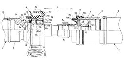
- FIG. 1 is an external view showing the external appearance of a propeller shaft to which the present invention is applied;
- FIG. 2 is an enlarged cross-sectional view showing an enlarged cross-section of the propeller shaft support device and its vicinity shown in FIG. 1 ;
- FIG. 3 is an enlarged cross-sectional view of the vicinity of the propeller shaft support device shown in FIG. 2 further enlarged;
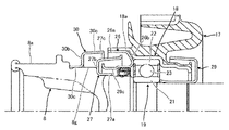
- FIG. 2 is a cross-sectional view of the vicinity of the propeller shaft support device according to the first embodiment of the present invention;
- FIG. 5 is an enlarged cross-sectional view showing an enlarged cross-section of the vicinity of the support device for the propeller shaft shown in FIG. 4;
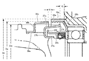
- FIG. 7 is a cross-sectional view of the vicinity of a propeller shaft support device according to a second embodiment of the present invention
- FIG. 8 is a cross-sectional view of the vicinity of a propeller shaft support device according to a third embodiment of the present invention
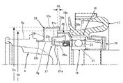
- FIG. 11 is a cross-sectional view of the vicinity of a propeller shaft support device according to a fourth embodiment of the present invention
- FIG. 11 is a cross-sectional view of the vicinity of a propeller shaft support device according to a fifth embodiment of the present invention
- FIG. 11 is a cross-sectional view of the vicinity of a propeller shaft support device according to a sixth embodiment of the present invention
- FIG. 1 The propeller shaft described below has already been proposed by the applicant.
- the propeller shaft to which the present invention is applied is applied to automobiles using four-wheel drive or front engine rear drive drive systems, and is connected to a transmission coupled to a power source such as an internal combustion engine.
- It consists mainly of a member, for example a support device 5 fixed to the lower part of the cross member 4 .
- the drive shaft 1 includes a drive-side tube 6 made of a steel pipe, a cardan joint 7 axially fixed to the front end of the drive-side tube 6 by welding, and axially fixed to the rear end of the drive-side tube 6 by welding. and a stub shaft 8.
- the driven shaft 2 includes a driven tube 9 made of a steel pipe, a constant velocity joint casing 10 which is axially fixed to the front end of the driven tube 9 by welding and into which the end of the stub shaft 8 is inserted, It is mainly composed of a cardan joint 11 axially fixed to the rear end of the driven tube 9 by welding.
- the stub shaft 8 is made of ferrous metal and has a stepped diameter. It has a stub medium diameter portion 8b and a stub small diameter portion 8c that are formed.
- a stub second large-diameter stepped portion having a smaller diameter than the stub large-diameter portion 8a and a larger diameter than the stub medium-diameter portion 8b is formed.
- 8d is formed between the stub second large-diameter stepped portion 8d and the stub medium-diameter portion 8b.
- a step surface 8f is formed between the stub intermediate stepped portion 8e and the stub intermediate stepped portion 8b.
- the constant velocity joint 3 is fixed to the front end of the driven shaft 2 and includes a constant velocity joint casing 10 which is an outer race formed in a substantially cylindrical shape, and a constant velocity joint casing 10 on the inner peripheral side of the constant velocity joint casing 10.
- a constant velocity joint casing 10 which is an outer race formed in a substantially cylindrical shape
- a constant velocity joint casing 10 on the inner peripheral side of the constant velocity joint casing 10.
- a plurality of torque transmission balls 13 rotatably provided between the constant velocity joint casing 10 and the inner race 12, and a cage 14 holding the torque transmission balls 13. It is configured.
- the constant velocity joint casing 10 has a plurality of grooves 10a formed along the axial direction on the inner peripheral side at substantially equal intervals in the circumferential direction.
- a plurality of recesses 12a are formed along the axial direction at substantially equal intervals along the circumferential direction corresponding to the grooves 10a.
- the interior of the constant velocity joint 3 is filled with lubricating oil such as grease, and a boot 15 made of rubber is attached to the front end side of the constant velocity joint casing 10 to seal the interior of the constant velocity joint casing 10. ing.
- the boot 15 is formed of a rubber material in a cylindrical shape having a stepped diameter. and a folded portion 15c which is bent in a substantially folded shape and whose tip end is fitted to the outer circumference of the stub small diameter portion 8c of the stub shaft 8. As shown in FIG. Further, a core material 15d is embedded inside the body portion 15a.
- the support device 5 includes a mounting bracket 16 which is an annular member mounted on the cross member 4 of the vehicle body, an elastic member 17 fixed inside the mounting bracket 16, and an elastic member 17. It is mainly composed of a metal inner ring 18 which is a supporting member fixed to the inner peripheral side of 17 and a center bearing 19 held inside the inner ring 18 .
- the inner ring 18 is formed in a cylindrical shape surrounding the outer peripheral side of the stub shaft 8 along the rotation axis of the stub shaft 8 that constitutes the shaft. That is, the stub shaft 8 is inserted through the inner ring 18 , and an annular gap is formed between the inner peripheral surface of the inner ring 18 and the outer peripheral surface of the stub shaft 8 . A center bearing 19 and a pressing ring 26 are accommodated in this annular gap.
- the elastic member 17 is made of a rubber material and has a horizontal U-shaped longitudinal section that opens toward the front of the vehicle body. 20 and the inner peripheral surface is vulcanized and bonded to the outer peripheral surface of the inner ring 18 .
- the inner ring 18 is formed of a thin metal plate into a cylindrical shape with a stepped diameter. It is composed of a middle-diameter annular portion 18b formed more continuously and provided on the outer peripheral side of the stub middle-diameter portion 8b, and a small-diameter annular portion 18c formed continuously from the middle-diameter annular portion 18b.
- the center bearing 19 includes an inner ring 21 press-fitted onto the outer periphery of the stub intermediate diameter portion 8b of the stub shaft 8, an outer ring 22 held on the inner periphery of the intermediate diameter annular portion 18b of the inner ring 18, the inner ring 21 and the outer ring 22. and a plurality of steel balls 23 rotatably held between arc-shaped holding grooves formed in the center of the facing surfaces of the rollers.
- Annular oil seals 24 and 25 are attached to both ends of the inner ring 21 and the outer ring 22 in the width direction.
- a pressing ring 26 that opens toward the front of the vehicle body is press-fitted and fixed to the inner peripheral side of the large-diameter annular portion 18a of the inner ring 18 .
- a dust cover 27 is press-fitted and fixed to the stub second large-diameter stepped portion 8d of the stub shaft 8 positioned on the front side of the vehicle body of the presser ring 26, and the other end thereof extends inside the opened interior of the presser ring 26.
- an annular seal member 28 is provided between the inner peripheral surface of the pressing ring 26 and the outer peripheral surface of the stub middle diameter stepped portion 8e.
- the pressing ring 26 is arranged so as to surround the other end of the dust cover 27, complicating the route for muddy water to enter the outer peripheral surface of the stub middle diameter stepped portion 8e of the stub shaft 8.
- a so-called labyrinth seal is formed to prevent muddy water from entering the outer peripheral surface of the stub middle diameter stepped portion 8 e of the stub shaft 8 .
- an annular seal member 28 is arranged between the inner peripheral surface of the presser ring 26 and the outer peripheral surface of the stub middle diameter stepped portion 8e to prevent muddy water from entering the center bearing 19 from the front of the vehicle. are preventing.
- a holding member 29 is provided that is press-fitted into the outer periphery of the stub medium diameter portion 8b of the stub shaft 8 to position and fix the center bearing 19 in the axial direction.
- the holding member 29 is formed by bending a thin metal plate into a substantially U-shaped cross section by press forming, and includes one end portion 29a press-fitted into the outer peripheral surface of the stub middle diameter portion 8b, and this one end portion 29a.
- the other end portion 29b extends radially from the rear edge of the portion 29a and is bent toward the center bearing 19 in a folded shape.
- One end portion 29a is formed in a substantially cylindrical shape, and a tip portion 29c on the side of the center bearing 19 is bent and formed to expand its diameter.
- the inner ring 21 is held in a sandwiched state in cooperation with the stepped surface 8f by abutting against the inner ring 21a from the axial direction. Therefore, since the inner ring 21 of the center bearing 19 is fixed in the axial direction, the whole can be firmly held.
- the other end portion 29b is composed of a bent portion 29e bent radially outward and a cylindrical portion 29f extending from the outer peripheral edge of the bent portion 29e toward the outer ring 22 of the center bearing 19.
- the portion 29e and the cylindrical portion 29f surround the small-diameter annular portion 18c of the inner ring 18 to shield the inside of the center bearing 19. As shown in FIG.
- the other end 29b of the holding member 29 surrounds the outer circumference of the small-diameter annular portion 18c of the inner ring 18, thereby complicating the entry path into the center bearing 19 and forming a so-called labyrinth seal.
- labyrinth seal there is As a result, it is possible to prevent muddy water from entering the center bearing 19 from the rear side of the inner ring 18 .
- the labyrinth seal can prevent muddy water from entering from the rear side of the vehicle body, a gap between the small-diameter annular portion 18c and the other end portion 29b of the inner ring 18 prevents muddy water from entering the inside of the center bearing 19. It is also possible to dispense with the annular sealing member that prevents this.
- the presser ring 26 is arranged so as to surround the other end of the dust cover 27 to form a labyrinth seal. Since a gap is formed between the center bearing 19 and the other end, muddy water or the like flying toward the gap may enter the inside of the center bearing 19 .
- a waterproof cover having an open portion extending close to the open portion of the holding ring is provided at a position sandwiching the dust cover on the open portion side of the holding ring of the propeller shaft, here, the stub shaft. It is characterized by
- the water impermeable cover is fixed to the position of the stub shaft on the open side of the presser ring, and the open part of the water impervious cover is extended so as to approach the open part of the presser ring to the extent that it does not come into contact with the presser ring. Even if muddy water, etc., flies obliquely toward the open part of the bearing, the water impermeable cover prevents muddy water, etc. from entering from the open part of the holding ring, and as a result, the phenomenon of muddy water, etc. entering the inside of the center bearing is prevented. hard to come by.
- FIG. 4 shows the configuration of the propeller shaft support portion
- FIG. 5 shows its enlarged portion.
- the pressing ring 26 when cross-sectioned along a plane parallel to the axis of rotation of the stub shaft 8, the pressing ring 26 has three regions, that is, a first annular region 26a and a second region continuing from the first annular region 26a. It is formed of an annular area portion 26b and a third annular area portion 26c continuing from the second annular area portion 26b.
- the first annular region portion 26 a is press-fitted and fixed to the large-diameter annular portion 18 a of the inner ring 18 , the second annular region portion 26 b extends closer to the stub shaft 8 side, and the outer ring 22 of the center bearing 19 . , the third annular region 26c extends to the opposite side of the center bearing 19 so that the annular seal member 28 extends radially and axially. restricts movement to
- first annular area portion 26a, the second annular area portion 26b, and the third annular area portion 26c are formed to have a substantially "U"-shaped cross section, and extend along the rotation axis of the stub shaft 8 to the first annular area portion 26a.
- An open portion is formed by the annular region portion 26a and the third annular region portion 26c.
- the first annular area portion 26 a and the third annular area portion 26 c extend toward the side opposite to the center bearing 19 .
- the dust cover 27 has three area portions, that is, a first cover area portion 27a, a second cover area portion 27b continuing from the first cover area portion 27a, and a third cover area portion 27c continuing from the second cover area portion 27b. is formed from The dust cover 27 is arranged on the side opposite to the center bearing 19 with the pressing ring 26 as a boundary.
- the first cover region portion 27a is press-fitted and fixed to the stub second large-diameter stepped portion 8d of the stub shaft 8, and the second cover region portion 27b extends radially outward with respect to the rotation axis of the stub shaft 8. Further, the third cover region portion 27c is formed so as to gradually widen (the outer diameter gradually increases) in the direction away from the rotation axis of the stub shaft 8 in the radial direction.
- first cover region portion 27a, the second cover region portion 27b, and the third cover region portion 27c are formed to have a substantially “U”-shaped cross section, and extend along the rotation axis of the stub shaft 8 to the first cover region portion 27a.
- An open portion is formed by the cover area portion 27a and the third cover area portion 27c.
- the first cover area portion 27a and the third cover area portion 27c extend toward the center bearing 19 side.
- the open portions of the pressing ring 26 and the dust cover 27 face each other, and the third annular region portion 26c and the third cover region portion 27c extend into the spaces of the respective open portions. It will be configured to be
- the open portion of the pressing ring 26 (formed by the first annular area portion 26a and the third annular area portion 26c) and the open portion of the dust cover 27 (the first cover area portion 27a and the third cover area portion 27c) ) are arranged facing each other.
- the third cover area portion 27c of the dust cover 27 is located between the first annular area portion 26a and the third annular area portion 26c forming the open portion of the pressing ring 26. extends into the space of As a result, a labyrinth is formed between the second annular area portion 26b of the pressing ring 26 and the tip 27t of the third cover area portion 27c of the dust cover 27. As shown in FIG.
- the third annular area portion 26c of the pressing ring 26 extends into the space between the first cover area portion 27a and the third cover area portion 27c that form the open portion of the dust cover 27. As shown in FIG. As a result, a labyrinth is formed between the second cover region portion 27b of the dust cover 27 and the tip 26t of the third annular region portion 26c of the pressing ring 26. As shown in FIG.
- the first cover region portion 27a of the dust cover 27 is bent toward the presser ring 26 and fixed to the stub shaft 8, as compared to the one shown in FIG. As a result, the length in the rotation axis direction can be shortened.
- the vicinity of the tip 27t of the third cover region portion 27c of the dust cover 27 is bent outward in a radial direction orthogonal to the rotation axis, so that the third cover region portion 27c is bent outward. This prevents the flowing muddy water from changing direction and flowing into the gap between the second annular area portion 26b of the pressing ring 26 and the tip end 27t of the third cover area portion 27c of the dust cover 27.
- the vicinity of the tip 26t of the third annular region portion 26c of the pressing ring 26 is bent outward in the radial direction orthogonal to the rotation axis, so that the muddy water flowing through the third annular region portion 26c changes direction. This prevents the dust from flowing into the gap between the second cover area 27b of the dust cover 27 and the tip 26t of the third annular area 26c of the pressing ring 26.
- the waterproof cover 30 which is a feature of this embodiment, will be described.
- the waterproof cover 30 is fixed to the stub shaft 8 at a position opposite to the pressing ring 26 with the dust cover 27 interposed therebetween.
- the impermeable cover 30 has three areas, namely, a first impermeable area 30a, a second impermeable area 30b continuing from the first impermeable area 30a, and a third impermeable area continuing from the second impermeable area 30b. It is formed from the impermeable region portion 30c.
- the first impermeable region 30a is fixed to the stub first large-diameter stepped portion 8g of the stub shaft 8, and the second impermeable region 30b extends radially outward with respect to the rotation axis of the stub shaft 8. Further, the third impermeable region 30c is formed so as to gradually widen (the outer diameter gradually increases) in the direction away from the rotation axis of the stub shaft 8 in the radial direction.
- an open portion is formed by the outer surface of the third waterproof region portion 30c and the stub shaft 8. Then, the second cover region portion 27b of the dust cover 27 and a part of the third cover region portion 27C of the dust cover 27 are accommodated in the open portion in a state of being overlapped in the direction of the rotation axis, and as a result, the third impervious region portion 30c is , the second cover area portion 27b and part of the third cover area portion 27C of the dust cover 27 are covered from the outside.
- the third waterproof region 30c is positioned outside the third cover region 27c of the dust cover 27 when viewed in the direction orthogonal to the rotation axis of the stub shaft 8, and
- the end face of the third waterproof region portion 30c is close to the end face of the first annular region portion 26a of the pressing ring 26 and faces them with a gap (g) interposed therebetween.
- the third waterproof region 30c overlaps the third cover region 27c.
- This gap (g) is determined to be shorter than the gap (G) formed by the tip 27t of the third cover region portion 27c of the dust cover 27 and the second annular region portion 26b of the pressing ring 26.
- the dust cover 27 is covered from the outside by both the pressing ring 26 and the waterproof cover 30 .
- the gap (g) is set to a length shorter than the axial length (Ls) of the third water impermeable region portion 30c of the water impermeable cover 30.
- the water impermeable cover 30 is arranged to cover the dust cover 27 from the outside, even if muddy water or the like flies obliquely toward the open portion side of the pressing ring 26, the water impermeable cover 30 does not Therefore, the risk of muddy water or the like entering from the open portion of the pressing ring 26 is suppressed, and as a result, the phenomenon of muddy water or the like entering the inside of the center bearing can be made difficult to occur.
- the maximum outer diameter (Ds) of the third impermeable region portion 30c overlapping the third cover region portion 27c is , equal to or smaller than the maximum outer diameter (Dr) of the large-diameter annular portion 18a of the inner ring 18, in other words, the length is determined not to exceed the maximum outer diameter (Dr) of the large-diameter annular portion 18a of the inner ring 18. ing.
- the waterproof cover 30 does not interfere when the stub shaft 8 is welded to the drive-side tube 6.
- the maximum outer diameter (Ds) of the third impermeable region 30c of the impermeable cover 30 is equal to the large-diameter annular diameter of the inner ring 18. It is determined to be smaller than the maximum outer diameter (Dr) of the portion 18 a and larger than the maximum outer diameter (Dd) of the dust cover 27 . This makes it possible to suppress the intrusion of muddy water.
- the outer diameter of the third impermeable region 30 c of the impermeable cover 30 is determined to gradually increase toward the center bearing 19 .
- the outer diameter of the third cover region 27c of the dust cover 27 is determined to gradually increase as it approaches the center bearing 19 when viewed in the rotation axis direction of the stub shaft 8. .
- a tip 27t is newly formed in the third cover area portion 27c of the dust cover 27 and extends outward (curves outward) in a radial direction orthogonal to the rotation axis of the stub shaft 8. As shown in FIG. This prevents the muddy water flowing through the third annular area 26c from changing direction and flowing into the gap between the second annular area 26b of the pressing ring 26 and the tip 27t of the third cover area 27c of the dust cover 27.
- the water impermeable cover 30 has a first water impermeable region 30a extending on the side opposite to the dust cover 27 and fixed to the stub shaft 8, and a third water impervious region 30c extending toward the dust cover 27.
- the cross-sectional shape is substantially an inverted "Z" shape in the drawing.
- the third water impermeable region 30c of the water impermeable cover 30 can overlap the third cover region 27c of the dust cover 27 with a small amount of material.
- the first cover area portion 27a is fixed to the stub shaft 8, but the first cover area portion 27a and the third cover area portion 27c extend toward the pressing ring 26. , and has a substantially "U"-shaped cross section. Thereby, the axial length of the stub shaft 8 can be shortened.
- the stub shaft 8 is provided with a stepped portion that abuts against the radial surface of the waterproof cover 30 when the waterproof cover 30 is attached so as to extend radially by the stub first large-diameter stepped portion 8g of the stub shaft 8. It is As a result, the impermeable cover 30 can be reliably positioned and fixed.
- the stub shaft 8 is formed with a first stub large-diameter stepped portion 8g and a second stub large-diameter stepped portion 8d having a smaller diameter than the first large-diameter stepped portion 8g. is fixed, and a dust cover 27 is fixed to the stub second large-diameter stepped portion 8d. Since a stepped portion is formed between the first stub large-diameter stepped portion 8g and the second large-diameter stepped portion 8d, the dust cover 27 can be reliably positioned and fixed.
- the annular seal member 28 arranged on the outer periphery of the stub shaft 8 is pressed radially by the third annular region portion 26c, thereby restricting the movement of the annular seal member 28, and , the sealing performance is improved.
- a tip 27t extending outward in a direction orthogonal to the rotation axis of the stub shaft 8 is formed at the tip of the third cover region portion 27c of the dust cover 27.
- a distal end portion 31t extending outward in a direction perpendicular to the rotation axis of the stub shaft 8 is formed at the distal end of the third waterproof region portion 31c of the waterproof cover 31 .
- the maximum outer diameter of the third impermeable region portion 32c ( Ds) is equal to or larger than the maximum outer diameter (Dr) of the large-diameter annular portion 18a of the inner ring 18, in other words, the length exceeds the maximum outer diameter (Dr) of the large-diameter annular portion 18a of the inner ring 18. It is decided.
- the third impermeable region 32c of the impermeable cover 32 covers the dust cover 27 from the outside. , the risk of muddy water or the like entering from the open portion of the presser ring 26 is suppressed, and as a result, the phenomenon of muddy water or the like entering the inside of the center bearing can be made difficult to occur.
- the maximum outer diameter of the third impermeable region portion 33c of the impervious cover 33 is made larger than the maximum outer diameter of the large-diameter annular portion 18a of the inner ring 18, and the third impermeable region portion 33c is It is characterized by extending to the large-diameter annular portion 18 a of the inner ring 18 .
- the same reference numerals are assigned to the same components as those shown in FIGS. 4 and 5, and the description thereof is omitted.
- the maximum outer diameter ( Ds) is equal to or larger than the maximum outer diameter (Dr) of the large-diameter annular portion 18a of the inner ring 18, in other words, the length exceeds the maximum outer diameter (Dr) of the large-diameter annular portion 18a of the inner ring 18. It is decided.
- the third waterproof region portion 33c extends toward the center bearing 19 beyond the end surface of the large-diameter annular portion 18a of the inner ring 18 and the end surface of the first annular region portion 26a of the pressing ring 26. As shown in FIG. That is, an overlapping region (OL) is formed between the tip of the third impermeable region portion 33c, the end surface of the large-diameter annular portion 18a of the inner ring 18, and the end surface of the first annular region portion 26a of the pressing ring 26.
- the water impermeable covers 30 to 33 have the first water impermeable regions 30a to 33a extending in the opposite direction to the pressing ring 26, fixed to the stub shaft 8, and the third impermeable regions 30c to 33a.
- 33c extends toward the presser ring 26 and has a substantially inverted "Z" cross-sectional shape in the drawing.
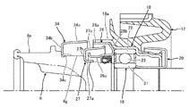
- the three impervious regions 34c both extend toward the pressing ring 26 and have a substantially "U"-shaped cross section. Thereby, the axial length of the stub shaft 8 can be shortened.
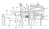
- the water impermeable cover 35 is arranged away from the pressing ring 26, and the tip of the third water impermeable area 35c of the water impermeable cover 35 and the second cover area 27b of the dust cover 27 are separated from each other.
- a gap is formed between the end face on the side of 35 and the waterproof cover 35 and the dust cover 27 are characterized in that they do not overlap each other.
- the same reference numerals are assigned to the same components as those shown in FIGS. 4 and 5, and the description thereof is omitted.
- the water impermeable covers 30 to 34 are provided with a region that overlaps the dust cover 27 when viewed from the rotation axis of the stub shaft 8 .
- the third impervious region 30c extends along the stub shaft 8 toward the dust cover 27 and further extends to the front of the dust cover 27 reaching the second cover region 27b.
- the tip of the third impervious region 30c is close to the end surface of the first annular region 26a of the pressing ring 26 so as to face it.
- the clearance (OD) is determined to be shorter than the clearance (g) shown in FIG.
- the end surface of the first annular area portion 26a of the pressing ring 26 and the end surface of the second cover area portion 27b of the dust cover 27 are at substantially the same position when viewed from the rotation axis line walking of the stub shaft 8. As shown in FIG.
- the third water impermeable region 35c of the water impermeable cover 35 has the same shape as the third water impermeable region 31c of the water impermeable cover 31 shown in FIG. That is, when viewed from the rotation axis of the stub shaft 8, the end face of the third impervious region 35c extends radially outward and is curved outward.
- the first impermeable region 35a of the impermeable cover 35 has the shape of the first impermeable region 34a of the impermeable cover 34 shown in FIG. That is, when viewed from the rotation axis of the stub shaft 8, the first water impermeable region 35a and the third water impermeable region 35c both extend toward the pressing ring 26 and have a substantially "U" cross-sectional shape. It is considered to be in the form of a shape.
- a water impermeable cover having an open portion extending close to the open portion of the holding ring is provided in addition to the dust cover at the position on the open portion side of the holding ring of the propeller shaft.
- the water impermeable cover is fixed to the position of the stub shaft on the side of the open portion of the presser ring, and the open portion of the water impervious cover is extended so as to be close to the open portion of the presser ring. Even if muddy water, etc., flies obliquely from the side, the water impermeable cover prevents muddy water, etc. from entering through the opening of the retaining ring. .
- the present invention is not limited to the several embodiments described above, and includes various modifications.
- the above embodiments have been described in detail for easy understanding of the present invention, and are not necessarily limited to those having all the described configurations.
- Other configurations can be added, deleted, or replaced with respect to the configuration of each embodiment.
Landscapes
- Engineering & Computer Science (AREA)
- General Engineering & Computer Science (AREA)
- Mechanical Engineering (AREA)
- Ocean & Marine Engineering (AREA)
- Motor Power Transmission Devices (AREA)
- Sealing Of Bearings (AREA)
- Sealing Using Fluids, Sealing Without Contact, And Removal Of Oil (AREA)
- Sealing Devices (AREA)
- Rolling Contact Bearings (AREA)
- Diaphragms And Bellows (AREA)
Abstract
Description
動力源の駆動力を伝達するプロペラシャフトにおいて、
第1端部と第2端部とを有したシャフトと、
シャフトの外周面に固定された内輪と、内輪の外周に配置された転動体と、転動体の外周に配置された外輪とを有したセンターベアリングと、
シャフトの回転軸線に沿ってシャフトの外周面を囲むように筒状に形成され、センターベアリングの外輪を保持する内環と、
シャフトの外周面と内環の内周面の間の環状隙間に配置され、シャフトの回転軸線で見て、内環の内周面に固定され、シャフトに沿ってセンターベアリングに向かう方向に延びる第1環状領域部と、第1環状領域部から続きシャフトに向かう方向に延びる第2環状領域部と、第2環状領域部から続きシャフトに沿ってセンターベアリングとは反対側に向かう方向に延びる第3環状領域部を有する押さえ環と、
押さえ環を境にしてセンターベアリングとは反対側のシャフトの外周面に配置され、シャフトの回転軸線で見て、シャフトの外周面に固定され、シャフトに沿って押さえ環に向かう方向に延びる第1カバー領域部と、第1カバー領域部から続きシャフトから遠ざかる方向に延びる第2カバー領域部と、第2カバー領域部から続きシャフトに沿って押さえ環に向かう方向に延びる第3カバー領域部を有するダストカバーと、
押さえ環とダストカバーの組み合わせによって、押さえ環の第1環状領域部と第3環状領域部の間に、ダストカバーの第3カバー領域部が延出され、ダストカバーの第1カバー領域部と第3カバー領域部の間に、押さえ環の第3環状領域部が延出されると共に、
ダストカバーを境にして押さえ環とは反対側のシャフトの外周面に配置され、シャフトの回転軸線で見て、シャフトの外周面に固定され、シャフトに沿って延びる第1遮水領域部と、第1遮水領域部から続きシャフトから遠ざかる方向に延びる第2遮水領域部と、第2遮水領域部から続きシャフトに沿ってダストカバーに向かう方向に延び、ダストカバーの第2カバー領域部及び第3カバー領域部の一部を外側から覆う第3遮水領域部を有する遮水カバーとを備える
ことを特徴としている。
そこで、本実施形態では、プロペラシャフト、ここではスタブ軸の押さえ環の開放部側でダストカバーを挟んだ位置に、押さえ環の開放部に近接するように延びる開放部を備える遮水カバーを設けたことを特徴としている。
これによってスタブ軸8を駆動側チューブ6と溶接するとき遮水カバー30が邪魔になることがない。
次に、本発明の第2の実施形態について、図6を用いて説明する。本実施形態では、遮水カバー31の第3遮水領域部31cの先端の形状を変更したことを特徴としている。尚、図4及び図5に示す構成要素と同じ構成要素については、同じ参照番号を付しており、これについては説明を省略している。
次に、本発明の第3の実施形態について、図7を用いて説明する。本実施形態では、遮水カバー31の第3遮水領域部32cの最大外径を、内環18の大径環状部18aの最大外径より大きくしたことを特徴としている。尚、図4及び図5に示す構成要素と同じ構成要素については、同じ参照番号を付しており、これについては説明を省略している。
次に、本発明の第4の実施形態について、図8を用いて説明する。本実施形態では、遮水カバー33の第3遮水領域部33cの最大外径を、内環18の大径環状部18aの最大外径より大きくし、しかも第3遮水領域部33cが、内環18の大径環状部18aまで延びていることを特徴としている。尚、図4及び図5に示す構成要素と同じ構成要素については、同じ参照番号を付しており、これについては説明を省略している。
次に、本発明の第5の実施形態について、図9を用いて説明する。本実施形態では、遮水カバー34の第1遮水領域部34aの形成方向を押さえ環26の側に向けて形成したことを特徴としている。尚、図4及び図5に示す構成要素と同じ構成要素については、同じ参照番号を付しており、これについては説明を省略している。
次に、本発明の第6の実施形態について、図10を用いて説明する。本実施形態では、遮水カバー35の配置位置を押さえ環26から遠ざけて、遮水カバー35の第3遮水領域部35cの先端と、ダストカバー27の第2カバー領域部27bの遮水カバー35の側の端面との間に隙間を形成し、遮水カバー35とダストカバー27が重なり合わない形態としたことを特徴としている。尚、図4及び図5に示す構成要素と同じ構成要素については、同じ参照番号を付しており、これについては説明を省略している。
Claims (18)
- 動力源の駆動力を伝達するプロペラシャフトにおいて、
第1端部と第2端部とを有したシャフトと、
前記シャフトの外周面に固定された内輪と、前記内輪の外周に配置された転動体と、前記転動体の外周に配置された外輪とを有したセンターベアリングと、
前記シャフトの回転軸線に沿って前記シャフトの前記外周面を囲むように筒状に形成され、前記センターベアリングの前記外輪を保持する内環と、
前記シャフトの前記外周面と前記内環の内周面の間の環状隙間に配置され、前記シャフトの回転軸線で見て、前記内環の前記内周面に固定され、前記シャフトに沿って前記センターベアリングに向かう方向に延びる第1環状領域部と、前記第1環状領域部から続き前記シャフトに向かう方向に延びる第2環状領域部と、前記第2環状領域部から続き前記シャフトに沿って前記センターベアリングとは反対側に向かう方向に延びる第3環状領域部を有する押さえ環と、
前記押さえ環を境にして前記センターベアリングとは反対側の前記シャフトの前記外周面に配置され、前記シャフトの回転軸線で見て、前記シャフトの前記外周面に固定され、前記シャフトに沿って前記押さえ環に向かう方向に延びる第1カバー領域部と、前記第1カバー領域部から続き前記シャフトから遠ざかる方向に延びる第2カバー領域部と、前記第2カバー領域部から続き前記シャフトに沿って前記押さえ環に向かう方向に延びる第3カバー領域部を有するダストカバーと、
前記押さえ環と前記ダストカバーの組み合わせによって、前記押さえ環の前記第1環状領域部と前記第3環状領域部の間に、前記ダストカバーの前記第3カバー領域部が延出され、前記ダストカバーの前記第1カバー領域部と前記第3カバー領域部の間に、前記押さえ環の前記第3環状領域部が延出されると共に、
前記ダストカバーを境にして前記押さえ環とは反対側の前記シャフトの前記外周面に配置され、前記シャフトの回転軸線で見て、前記シャフトの前記外周面に固定され、前記シャフトに沿って延びる第1遮水領域部と、前記第1遮水領域部から続き前記シャフトから遠ざかる方向に延びる第2遮水領域部と、前記第2遮水領域部から続き前記シャフトに沿って前記ダストカバーに向かう方向に延び、前記ダストカバーの前記第2カバー領域部及び前記第3カバー領域部の一部を外側から覆う第3遮水領域部を有する遮水カバーと
を備えることを特徴とするプロペラシャフト。 - 請求項1に記載のプロペラシャフトにおいて、
前記遮水カバーの前記第3遮水領域部の最大外径は、前記内環の最大外径と同等、若しくは小さく決定されている
ことを特徴とするプロペラシャフト。 - 請求項2に記載のプロペラシャフトにおいて、
前記遮水カバーの前記第3遮水領域部の外径は、前記内環の最大外径より小さく、前記ダストカバーの最外径よりも大きく決められている
ことを特徴とするプロペラシャフト。 - 請求項1に記載のプロペラシャフトにおいて、
前記遮水カバーの前記第3遮水領域部は、前記シャフトの回転軸線から離れる方向に、徐々に拡開する形状である
ことを特徴とするプロペラシャフト。 - 請求項1に記載のプロペラシャフトにおいて、
前記ダストカバーの前記第3カバー領域部は、前記シャフトの回転軸線から離れる方向に、徐々に拡開する形状である
ことを特徴とするプロペラシャフト。 - 請求項1に記載のプロペラシャフトにおいて、
前記遮水カバーは、前記第1遮水領域部が前記ダストカバーとは反対側に延び、前記第3遮水領域部が前記ダストカバーの側に延びている
ことを特徴とするプロペラシャフト。 - 請求項1に記載のプロペラシャフトにおいて、
前記ダストカバーは、前記第1カバー領域部と前記第3カバー領域部が、前記押さえ環の方に向けて延びている
ことを特徴とするプロペラシャフト。 - 請求項1に記載のプロペラシャフトにおいて、
前記シャフトには、前記遮水カバーの径方向の面と突き当たる段部が形成されている
ことを特徴とするプロペラシャフト。 - 請求項1に記載のプロペラシャフトにおいて、
前記シャフトには、前記遮水カバーが固定される第1外径部と、前記センターベアリングが固定される前記第1外径部よりも小径の第2外径部が形成され、前記第1外径部と前記第2外径部の間の部分に、前記ダストカバーが固定されている
ことを特徴とするプロペラシャフト。 - 請求項1に記載のプロペラシャフトにおいて、
前記押さえ環の前記第3環状領域部と前記シャフトの前記外周面には、環状シール部材が配置されている
ことを特徴とするプロペラシャフト。 - 請求項1に記載のプロペラシャフトにおいて、
前記ダストカバーの前記第3カバー領域部の先端、及び/又は前記遮水カバーの前記第3遮水領域部の先端は、前記シャフトの回転軸線に直交する方向で外側に向かって延びている
ことを特徴とするプロペラシャフト。 - 請求項1に記載のプロペラシャフトにおいて、
前記遮水カバーの前記第3遮水領域部の最大外径は、前記内環の最大外径と同等、若しくは大きく決定されている
ことを特徴とするプロペラシャフト。 - 請求項1に記載のプロペラシャフトにおいて、
前記遮水カバーの前記第3遮水領域部の最大外径は、前記内環の最大外径より大きく決定され、更に前記第3遮水領域部は、前記ダストカバー及び前記内環の一部を外側から覆うように延びている
ことを特徴とするプロペラシャフト。 - 請求項1に記載のプロペラシャフトにおいて、
前記遮水カバーは、前記第1遮水領域部と前記第3遮水領域部が、前記ダストカバーの方に向けて延びている
ことを特徴とするプロペラシャフト。 - 動力源の駆動力を伝達するプロペラシャフトにおいて、
第1端部と第2端部とを有したシャフトと、
前記シャフトの外周面に固定された内輪と、前記内輪の外周に配置された転動体と、前記転動体の外周に配置された外輪とを有したセンターベアリングと、
前記シャフトの回転軸線に沿って前記シャフトの前記外周面を囲むように筒状に形成され、前記センターベアリングの前記外輪を保持する内環と、
前記シャフトの前記外周面と前記内環の内周面の間の環状隙間に配置され、前記シャフトの回転軸線で見て、前記内環の前記内周面に固定され、前記シャフトに沿って前記センターベアリングに向かう方向に延びる第1環状領域部と、前記第1環状領域部から続き前記シャフトに向かう方向に延びる第2環状領域部と、前記第2環状領域部から続き前記シャフトに沿って前記センターベアリングとは反対側に向かう方向に延びる第3環状領域部を有する押さえ環と、
前記押さえ環を境にして前記センターベアリングとは反対側の前記シャフトの前記外周面に配置され、前記シャフトの回転軸線で見て、前記シャフトの前記外周面に固定され、前記シャフトに沿って前記押さえ環に向かう方向に延びる第1カバー領域部と、前記第1カバー領域部から続き前記シャフトから遠ざかる方向に延びる第2カバー領域部と、前記第2カバー領域部から続き前記シャフトに沿って前記押さえ環に向かう方向に延びる第3カバー領域部を有するダストカバーと、
前記押さえ環と前記ダストカバーの組み合わせによって、前記押さえ環の前記第1環状領域部と前記第3環状領域部の間に、前記ダストカバーの前記第3カバー領域部が延出され、前記ダストカバーの前記第1カバー領域部と前記第3カバー領域部の間に、前記押さえ環の前記第3環状領域部が延出されると共に、
前記ダストカバーを境にして前記押さえ環とは反対側の前記シャフトの前記外周面に配置され、前記シャフトの回転軸線で見て、前記シャフトの前記外周面に固定され、前記シャフトに沿って延びる第1遮水領域部と、前記第1遮水領域部から続き前記シャフトから遠ざかる方向に延びる第2遮水領域部と、前記第2遮水領域部から続き前記シャフトに沿って前記ダストカバーに向かう方向に延び、前記ダストカバーの前記第2カバー領域部及び前記第3カバー領域部の一部を外側から覆う第3遮水領域部を有する遮水カバーとを備え、
更に、前記シャフトの回転軸線の方向で見て、前記遮水カバーの前記第3遮水領域部の長さに比べて、前記遮水カバーの前記第3遮水領域部の先端と向き合う前記押さえ環の前記第1環状領域部の先端と前記第3遮水領域部の先端との間の長さの方が短く決められている
ことを特徴とするプロペラシャフト。 - 請求項15に記載のプロペラシャフトにおいて、
前記ダストカバーの前記第3カバー領域部の先端、及び/又は前記遮水カバーの前記第3遮水領域部の先端は、前記シャフトの回転軸線に直交する方向で外側に向かって延びている
ことを特徴とするプロペラシャフト。 - 動力源の駆動力を伝達するプロペラシャフトにおいて、
第1端部と第2端部とを有したシャフトと、
前記シャフトの外周面に固定された内輪と、前記内輪の外周に配置された転動体と、前記転動体の外周に配置された外輪とを有したセンターベアリングと、
前記シャフトの回転軸線に沿って前記シャフトの前記外周面を囲むように筒状に形成され、前記センターベアリングの前記外輪を保持する内環と、
前記シャフトの前記外周面と前記内環の内周面の間の環状隙間に配置され、前記シャフトの回転軸線で見て、前記内環の前記内周面に固定され、前記シャフトに沿って前記センターベアリングに向かう方向に延びる第1環状領域部と、前記第1環状領域部から続き前記シャフトに向かう方向に延びる第2環状領域部と、前記第2環状領域部から続き前記シャフトに沿って前記センターベアリングとは反対側に向かう方向に延びる第3環状領域部を有する押さえ環と、
前記押さえ環を境にして前記センターベアリングとは反対側の前記シャフトの前記外周面に配置され、前記シャフトの回転軸線で見て、前記シャフトの前記外周面に固定され、前記シャフトに沿って前記押さえ環に向かう方向に延びる第1カバー領域部と、前記第1カバー領域部から続き前記シャフトから遠ざかる方向に延びる第2カバー領域部と、前記第2カバー領域部から続き前記シャフトに沿って前記押さえ環に向かう方向に延びる第3カバー領域部を有するダストカバーと、
前記押さえ環と前記ダストカバーの組み合わせによって、前記押さえ環の前記第1環状領域部と前記第3環状領域部の間に、前記ダストカバーの前記第3カバー領域部が延出され、前記ダストカバーの前記第1カバー領域部と前記第3カバー領域部の間に、前記押さえ環の前記第3環状領域部が延出されると共に、
前記ダストカバーを境にして前記押さえ環とは反対側の前記シャフトの前記外周面に配置され、前記シャフトの回転軸線で見て、前記シャフトの前記外周面に固定され、前記シャフトに沿って延びる第1遮水領域部と、前記第1遮水領域部から続き前記シャフトから遠ざかる方向に延びる第2遮水領域部と、前記第2遮水領域部から続き前記シャフトに沿って前記ダストカバーに向かう方向で、前記ダストカバーの前記第2カバー領域部に至る手前まで延びる第3遮水領域部を有する遮水カバーと
を備えることを特徴とするプロペラシャフト。 - 請求項17に記載のプロペラシャフトにおいて、
前記遮水カバーの前記第3遮水領域部の最大外径は、前記ダストカバーの前記第3カバー領域部の最大外径より大きく決められている
ことを特徴とするプロペラシャフト。
Priority Applications (2)
| Application Number | Priority Date | Filing Date | Title |
|---|---|---|---|
| CN202180094258.0A CN116887999A (zh) | 2021-02-22 | 2021-12-16 | 传动轴 |
| US18/277,945 US12601380B2 (en) | 2021-02-22 | 2021-12-16 | Propeller shaft |
Applications Claiming Priority (2)
| Application Number | Priority Date | Filing Date | Title |
|---|---|---|---|
| JP2021026516A JP7492470B2 (ja) | 2021-02-22 | 2021-02-22 | プロペラシャフト |
| JP2021-026516 | 2021-12-02 |
Publications (1)
| Publication Number | Publication Date |
|---|---|
| WO2022176362A1 true WO2022176362A1 (ja) | 2022-08-25 |
Family
ID=82930499
Family Applications (1)
| Application Number | Title | Priority Date | Filing Date |
|---|---|---|---|
| PCT/JP2021/046411 Ceased WO2022176362A1 (ja) | 2021-02-22 | 2021-12-16 | プロペラシャフト |
Country Status (4)
| Country | Link |
|---|---|
| US (1) | US12601380B2 (ja) |
| JP (2) | JP7492470B2 (ja) |
| CN (1) | CN116887999A (ja) |
| WO (1) | WO2022176362A1 (ja) |
Cited By (1)
| Publication number | Priority date | Publication date | Assignee | Title |
|---|---|---|---|---|
| CN117067904A (zh) * | 2023-10-18 | 2023-11-17 | 万向钱潮股份公司 | 一种支架总成、传动轴连接结构、传动轴及汽车 |
Citations (6)
| Publication number | Priority date | Publication date | Assignee | Title |
|---|---|---|---|---|
| US2927825A (en) * | 1956-12-03 | 1960-03-08 | Gen Motors Corp | Bearing support |
| JPS59231209A (ja) * | 1983-06-09 | 1984-12-25 | ジー・ケー・エヌ・オートモーティヴ・アクチェンゲゼルシャフト | 駆動軸 |
| JPH0434005B2 (ja) * | 1979-04-24 | 1992-06-04 | Glaenzer Spicer Sa | |
| JP2007106359A (ja) * | 2005-10-17 | 2007-04-26 | Fuji Heavy Ind Ltd | 車両用プロペラシャフトのセンターマウント構造 |
| JP2009006990A (ja) * | 2007-05-25 | 2009-01-15 | Hitachi Ltd | プロペラシャフトおよび該プロペラシャフトの支持装置 |
| JP2019048560A (ja) * | 2017-09-11 | 2019-03-28 | 日立オートモティブシステムズ株式会社 | 車両の動力伝達軸 |
Family Cites Families (7)
| Publication number | Priority date | Publication date | Assignee | Title |
|---|---|---|---|---|
| JPS6271725A (ja) * | 1985-09-25 | 1987-04-02 | Honda Motor Co Ltd | 前輪駆動車輌の中間軸支持構造 |
| JP3958621B2 (ja) * | 2002-04-22 | 2007-08-15 | 株式会社日立製作所 | 動力伝達装置の緩衝機構 |
| US8628250B2 (en) | 2007-05-25 | 2014-01-14 | Hitchi, Ltd. | Support device for supporting propeller shaft and propeller shaft itself |
| JP6296552B2 (ja) * | 2014-09-11 | 2018-03-20 | 株式会社ショーワ | ブラケット組み立て体 |
| JP6527332B2 (ja) | 2015-01-05 | 2019-06-05 | Nok株式会社 | センターベアリングサポート |
| JP2025071725A (ja) * | 2023-10-23 | 2025-05-08 | ローレルバンクマシン株式会社 | 硬貨処理装置 |
| JP2024071725A (ja) * | 2024-03-29 | 2024-05-24 | 住友精化株式会社 | ポリマー含有組成物 |
-
2021
- 2021-02-22 JP JP2021026516A patent/JP7492470B2/ja active Active
- 2021-12-16 CN CN202180094258.0A patent/CN116887999A/zh active Pending
- 2021-12-16 WO PCT/JP2021/046411 patent/WO2022176362A1/ja not_active Ceased
- 2021-12-16 US US18/277,945 patent/US12601380B2/en active Active
-
2024
- 2024-04-03 JP JP2024059845A patent/JP7624104B2/ja active Active
Patent Citations (6)
| Publication number | Priority date | Publication date | Assignee | Title |
|---|---|---|---|---|
| US2927825A (en) * | 1956-12-03 | 1960-03-08 | Gen Motors Corp | Bearing support |
| JPH0434005B2 (ja) * | 1979-04-24 | 1992-06-04 | Glaenzer Spicer Sa | |
| JPS59231209A (ja) * | 1983-06-09 | 1984-12-25 | ジー・ケー・エヌ・オートモーティヴ・アクチェンゲゼルシャフト | 駆動軸 |
| JP2007106359A (ja) * | 2005-10-17 | 2007-04-26 | Fuji Heavy Ind Ltd | 車両用プロペラシャフトのセンターマウント構造 |
| JP2009006990A (ja) * | 2007-05-25 | 2009-01-15 | Hitachi Ltd | プロペラシャフトおよび該プロペラシャフトの支持装置 |
| JP2019048560A (ja) * | 2017-09-11 | 2019-03-28 | 日立オートモティブシステムズ株式会社 | 車両の動力伝達軸 |
Cited By (1)
| Publication number | Priority date | Publication date | Assignee | Title |
|---|---|---|---|---|
| CN117067904A (zh) * | 2023-10-18 | 2023-11-17 | 万向钱潮股份公司 | 一种支架总成、传动轴连接结构、传动轴及汽车 |
Also Published As
| Publication number | Publication date |
|---|---|
| JP2024091661A (ja) | 2024-07-05 |
| US12601380B2 (en) | 2026-04-14 |
| JP2022128147A (ja) | 2022-09-01 |
| CN116887999A (zh) | 2023-10-13 |
| JP7492470B2 (ja) | 2024-05-29 |
| US20240133468A1 (en) | 2024-04-25 |
| US20240229936A9 (en) | 2024-07-11 |
| JP7624104B2 (ja) | 2025-01-29 |
Similar Documents
| Publication | Publication Date | Title |
|---|---|---|
| US7922394B2 (en) | Propeller shaft for motor vehicle | |
| JP6526387B2 (ja) | 密封装置 | |
| JP2010180896A (ja) | 車輪用軸受シールおよびこれを備えた車輪用軸受装置 | |
| CN211778585U (zh) | 轮毂单元轴承 | |
| US20080293502A1 (en) | Support device for supporting propeller shaft and propeller shaft itself | |
| JP7624104B2 (ja) | プロペラシャフト | |
| JP2013231470A (ja) | 密封構造 | |
| KR102544727B1 (ko) | 드라이브 액슬의 부트조립체 | |
| KR102873865B1 (ko) | 차량의 구동륜 액슬장치 | |
| JP7437723B2 (ja) | 密封装置 | |
| KR20220144075A (ko) | 드라이브 액슬 조립체 | |
| JP6985881B2 (ja) | 車輪用軸受装置 | |
| JPH0118892Y2 (ja) | ||
| JP2005337446A (ja) | 密封型転がり軸受 | |
| JP2011158017A (ja) | 密封装置 | |
| JP2015227673A (ja) | 車輪用軸受装置 | |
| JP2012163175A (ja) | 密封装置 | |
| JP2007270873A (ja) | 密封装置 | |
| KR20230040373A (ko) | 휠 베어링용 실링 배열, 및 실링 배열을 포함하는 휠 베어링 유닛 | |
| JP2022149089A (ja) | ハブユニット軸受 | |
| JP6757221B2 (ja) | 農機具の車軸用密封装置 | |
| JP6839948B2 (ja) | 農機具の車軸用密封装置 | |
| WO2016021649A1 (ja) | 車輪用軸受装置 | |
| WO2021005882A1 (ja) | 密封装置および密封構造 | |
| JP4960819B2 (ja) | プロペラシャフトの支持装置 |
Legal Events
| Date | Code | Title | Description |
|---|---|---|---|
| 121 | Ep: the epo has been informed by wipo that ep was designated in this application |
Ref document number: 21926786 Country of ref document: EP Kind code of ref document: A1 |
|
| WWE | Wipo information: entry into national phase |
Ref document number: 18277945 Country of ref document: US |
|
| WWE | Wipo information: entry into national phase |
Ref document number: 202180094258.0 Country of ref document: CN |
|
| NENP | Non-entry into the national phase |
Ref country code: DE |
|
| 122 | Ep: pct application non-entry in european phase |
Ref document number: 21926786 Country of ref document: EP Kind code of ref document: A1 |
|
| WWG | Wipo information: grant in national office |
Ref document number: 18277945 Country of ref document: US |