WO2022171754A1 - Dispositif de deplacement d'une charge roulant sur des rails - Google Patents
Dispositif de deplacement d'une charge roulant sur des rails Download PDFInfo
- Publication number
- WO2022171754A1 WO2022171754A1 PCT/EP2022/053281 EP2022053281W WO2022171754A1 WO 2022171754 A1 WO2022171754 A1 WO 2022171754A1 EP 2022053281 W EP2022053281 W EP 2022053281W WO 2022171754 A1 WO2022171754 A1 WO 2022171754A1
- Authority
- WO
- WIPO (PCT)
- Prior art keywords
- wheel
- geared motor
- shaft
- arm
- displacement device
- Prior art date
- Legal status (The legal status is an assumption and is not a legal conclusion. Google has not performed a legal analysis and makes no representation as to the accuracy of the status listed.)
- Ceased
Links
Images






Classifications
-
- B—PERFORMING OPERATIONS; TRANSPORTING
- B61—RAILWAYS
- B61J—SHIFTING OR SHUNTING OF RAIL VEHICLES
- B61J3/00—Shunting or short-distance haulage devices; Similar devices for hauling trains on steep gradients or as starting aids; Car propelling devices therefor
- B61J3/12—Self-propelled tractors or pushing vehicles, e.g. mules
-
- A—HUMAN NECESSITIES
- A63—SPORTS; GAMES; AMUSEMENTS
- A63C—SKATES; SKIS; ROLLER SKATES; DESIGN OR LAYOUT OF COURTS, RINKS OR THE LIKE
- A63C17/00—Roller skates; Skate-boards
- A63C17/14—Roller skates; Skate-boards with brakes, e.g. toe stoppers, freewheel roller clutches
- A63C17/1409—Roller skates; Skate-boards with brakes, e.g. toe stoppers, freewheel roller clutches contacting one or more of the wheels
- A63C17/1427—Roller skates; Skate-boards with brakes, e.g. toe stoppers, freewheel roller clutches contacting one or more of the wheels the brake contacting other wheel associated surfaces, e.g. hubs, brake discs or wheel flanks
-
- B—PERFORMING OPERATIONS; TRANSPORTING
- B62—LAND VEHICLES FOR TRAVELLING OTHERWISE THAN ON RAILS
- B62D—MOTOR VEHICLES; TRAILERS
- B62D57/00—Vehicles characterised by having other propulsion or other ground- engaging means than wheels or endless track, alone or in addition to wheels or endless track
- B62D57/02—Vehicles characterised by having other propulsion or other ground- engaging means than wheels or endless track, alone or in addition to wheels or endless track with ground-engaging propulsion means, e.g. walking members
-
- B—PERFORMING OPERATIONS; TRANSPORTING
- B62—LAND VEHICLES FOR TRAVELLING OTHERWISE THAN ON RAILS
- B62D—MOTOR VEHICLES; TRAILERS
- B62D57/00—Vehicles characterised by having other propulsion or other ground- engaging means than wheels or endless track, alone or in addition to wheels or endless track
- B62D57/02—Vehicles characterised by having other propulsion or other ground- engaging means than wheels or endless track, alone or in addition to wheels or endless track with ground-engaging propulsion means, e.g. walking members
- B62D57/028—Vehicles characterised by having other propulsion or other ground- engaging means than wheels or endless track, alone or in addition to wheels or endless track with ground-engaging propulsion means, e.g. walking members having wheels and mechanical legs
-
- B—PERFORMING OPERATIONS; TRANSPORTING
- B62—LAND VEHICLES FOR TRAVELLING OTHERWISE THAN ON RAILS
- B62D—MOTOR VEHICLES; TRAILERS
- B62D57/00—Vehicles characterised by having other propulsion or other ground- engaging means than wheels or endless track, alone or in addition to wheels or endless track
- B62D57/02—Vehicles characterised by having other propulsion or other ground- engaging means than wheels or endless track, alone or in addition to wheels or endless track with ground-engaging propulsion means, e.g. walking members
- B62D57/032—Vehicles characterised by having other propulsion or other ground- engaging means than wheels or endless track, alone or in addition to wheels or endless track with ground-engaging propulsion means, e.g. walking members with alternately or sequentially lifted supporting base and legs; with alternately or sequentially lifted feet or skid
Definitions
- the present invention relates to the field of devices for moving heavy rolling loads, and more specifically devices for moving heavy loads rolling on railway tracks.
- displacement devices comprising in particular a roller driven by a motor and engaged against the running surface of one of the wheels of said rolling loads so as to set the latter in motion.
- a drive device comprising a transportable carriage equipped with two rolling cylinders and a driving cylinder actuated by a traction motor and arranged above said rolling cylinders so that when the driving device is brought into contact with the wheel of a rolling load, a frictional contact is established between the driving cylinder and the rolling cylinders, which causes the carriage to move during rotation of the drive cylinder and, at the same time, the displacement of the rolling load by the rotation of its wheel driven by the rotation of the drive cylinder.
- the carriage further has a handle in which the cables, sheaths or similar elements for supplying energy to the motor are preferably fitted and which has control mechanisms such as switches or similar elements.
- This type of drive device is effective but has the major drawback of having to be placed only at one end of the rolling load to be moved, so it cannot be placed between the axles of the latter. . Furthermore, this type of drive device requires the use of very long power supply cables. Finally, with this type of drive device, once in motion, the rolling load will not stop at a given position, but only when its kinetic energy is zero.
- the object of the present invention is therefore to overcome the drawbacks mentioned above and to propose an alternative to the known rolling load drive devices, this alternative being autonomous, compact, easy to move and to implement by a single operator whatever or the place of its implementation on said rolling load and making it possible to easily stop the latter at a given position.
- a device for moving a load provided with wheels and rolling on rails comprising at least: - a geared motor whose axis of rotation of its shaft is horizontal, - a drive roller fixed to the free end of the shaft of the geared motor and driven in rotation by the latter, said drive roller being arranged to bear against one of the wheels of the load to be moved, and - two support rollers arranged to come to rest on the rail of the railway receiving said wheel of the load to be moved and configured to be driven in rotation by adhesion by said drive roller, said displacement device being remarkable in that it comprises at least: - an arm secured by one of its ends to the shaft of the geared motor and extending horizontally and perpendicular to the axis of rotation of said shaft, and - a braking pad integral with the free end of said arm and arranged to, on the one hand, be arranged near said wheel of the load to be moved on the side opposite to said drive roller and, on the other hand, come into support on
- the displacement device according to the invention comprises only a single geared motor assembly - drive and support rollers, which makes the device more compact and less heavy while by allowing the rolling load to be easily stopped at a given position.
- the arm is advantageously adjustable in length.
- the arm is pivotally mounted on the shaft of the geared motor around the axis of rotation of the latter and in that the braking pad is pivotally mounted at the end of the associated arm around an axis of rotation parallel to the axis of rotation of the gearmotor shaft.
- This particular configuration makes it possible to place the braking pad on one side or the other of the wheel of the rolling load in order, if necessary, to facilitate the implementation of the device for moving a load according to the invention.
- the arm advantageously comprises a joint arranged on the side of the end secured to the shaft of the geared motor and allowing said arm to pass from an "unfolded" position in which it is completely straight to a "folded” position.
- the braking pad is preferably a section of cylinder of generally isosceles triangular cross-section comprising a horizontal lower face arranged to rest on the rail and two inclined faces arranged to receive the wheel of the load.
- the braking pad is advantageously made of elastomer.
- the moving device comprises a guide plate integral with at least the support rollers on the side opposite the geared motor and extending on the side opposite the drive roller beyond said support rollers, and a guide plate secured to the braking shoe on the side opposite the geared motor and extending from the side opposite the inclined faces of said braking shoe beyond the underside of the latter.
- the guide plate secured to the braking pad is preferably associated with a retractable guide plate secured to the braking pad on the side of the geared motor and which may or may not extend beyond the underside of said braking pad 9.
- the displacement device comprises a carriage containing at least in part the gear motor, the drive roller, the two support rollers, the arm and the braking pad, said gear motor being oriented so that its shaft extends beyond from the front face of the carriage, said carriage being provided, on the one hand, with at least one first retractable wheel making it possible to easily move said moving device on the ground from its place of storage to its place of use and , on the other hand, at least one second wheel replacing the first wheel(s) for moving said moving device, when the latter is used to roll a load to be moved.
- Each second wheel is advantageously adjustable in height and of the "jockey" wheel type.
- Said displacement device preferably comprises:
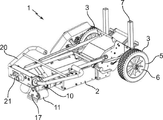
- FIG. 1 is a front perspective view of a rolling load drive device according to the invention.
- FIG. 1 is a rear perspective view of the driving device of the .
- FIG. 1 is a front perspective view of the drive device according to the invention in the folded position
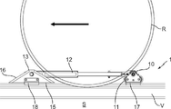
- FIG. 1 is a partial view of the front face of the drive device of the implemented on a wheel of a rolling load
- FIG. 1 to 8 there is shown a device 1 for moving a rolling load, not shown in the figures, such as, for example, wagons, convoys of wagons or even locomotives, and provided with wheels R configured to ride on V rails of train tracks.
- a device 1 for moving a rolling load such as, for example, wagons, convoys of wagons or even locomotives, and provided with wheels R configured to ride on V rails of train tracks.
- V rails are assumed to be horizontal, but that they can also be more or less inclined with respect to the horizontal, the terms: horizontal, horizontally, vertical or even vertically, will then have to be adapted.
- the moving device 1 comprises a carriage 2 provided, on the one hand, with at least one first wheel 3, advantageously two for an obvious reason of stability, making it possible to move easily on a ground S said displacement device 1 from its place of storage to its place of use and, on the other hand, at least one second wheel 4, advantageously two for an obvious reason of stability, replacing the first wheel(s) 3 for moving said moving device 1, when the latter is used to roll a load to be moved.
- each first wheel 3 preferably comprises a tire 5 mounted on a rim 6 and is pivotally mounted on the carriage 2 around a horizontal axis perpendicular to the sagittal plane (vertical plane, oriented from front to rear) of said displacement device 1.
- front designates here any element or part of an element of the movement device 1, according to the invention, located on the side of the front of the latter in its direction D of normal movement, represented by the arrow on the , and by “rear” any element or part of an element of said movement device 1 located on the opposite side.
- each first wheel 3 is advantageously retractable vertically between a "low” position in which the second wheel(s) is resting on the ground S ( s) wheel(s) 4 then not being in contact with said ground S, and a "high” position in which is no longer in contact with the ground S, the second wheel(s) 4 then resting on said ground S so as to allow movement of the moving device 1 when it is used to roll a load to be moved.
- each second wheel 4 is advantageously adjustable in height.
- each second wheel 4 is attached to the carriage 2 by means of a vertical section 7 adjustable in length.
- each second wheel 4 is advantageously of the "jockey" wheel type and pivots around a horizontal axis, but can also pivot around a vertical axis.
- the displacement device 1 comprises at least the following elements contained at least in part in the carriage 2: - a geared motor 8 whose axis of rotation of its shaft 9 is horizontal and is parallel, and preferably belongs, to the sagittal plane of the displacement device 1, said geared motor 8 being oriented so that its shaft 9 extends beyond from the front face of carriage 2, - a drive roller 10 fixed to the free end of the shaft 9 of the geared motor 8 and therefore driven in rotation by the latter, said drive roller 10 being arranged to bear against one of the wheels R of the load (see ) to move, and - two support rollers 11 arranged to bear against one of the rails V of the railway track receiving said wheel R of the load to be moved and configured to be driven in rotation by adhesion by said drive roller 10.
- said support rollers 11 are pivoted around horizontal axes, coplanar and parallel to the axis of rotation of the shaft 9 of the geared motor 8 and arranged on either side of said drive roller 10 and lower than the latter so that, when said drive roller 10 rotates, it drives with it in rotation by adhesion the two support rollers 11.
- the displacement device 1 further comprises: - an arm 12 secured by one of its ends to the shaft 9 of the geared motor 8 and extending horizontally and perpendicular to the axis of rotation of said shaft 9, and - a braking pad 13 secured to the free end of said arm 12 and arranged to, on the one hand, be arranged close to said wheel R of the load (Cf. ) to move to the opposite side and, on the other hand, come to rest on the rail V of the railway receiving said wheel R.
- the displacement device 1 may comprise only one support roller 11 without departing from the scope of the present invention. However, it is well understood that for obvious reasons of stability, the displacement device 1 will advantageously comprise two support rollers 11 arranged according to the configuration described above.
- the drive rollers 10 and support rollers 11 are each coated with a polymer coating.
- the arm 12 is advantageously adjustable in length.
- the arm 12 is advantageously pivotally mounted on the shaft 9 of the geared motor 8 around the axis of rotation of the latter in order to position the braking pad 13 on one side or the other of said drive roller assembly 10 - rollers d 'support 11.
- the braking pad 13 will be pivotally mounted at the end of the arm 12 associated around an axis of rotation parallel to the axis of rotation of the shaft 9 of the geared motor 8 in order to correctly position the bearing face of the braking shoe 13 on the rail V of the railway receiving said wheel R.
- the arm 12 comprises a joint 14 arranged on the side of the end secured to the shaft 9 of the geared motor 8 and allowing said arm 12 to pass from an "unfolded" position in which it is completely straight to a position "folded” in which the portion of the arm 12 going from the joint 14 to the braking pad 13 pivots to form an angle of between 60° and 120°, advantageously equal to 90°, with the portion of the arm 12 going from the joint 14 to shaft 9 of gearmotor 8.
- the braking pad 13 is a section of cylinder of globally isosceles triangular cross-section comprising a horizontal lower face 15 arranged to rest on the rail V and two inclined faces 16 arranged to receive the wheel R of the load .
- the braking pad 13 is made of elastomer.
- the drive roller assembly 10 - support rollers 11 and the braking pad 13 each comprise at least one guide plate 17,18 arranged to bear against the edge of said rail V.
- the guide plate 17 is integral with at least the support rollers 11 on the side opposite the gear motor 8 and extends on the side opposite the drive roller 10 beyond said rollers support 11.
- the guide plate 18 is integral with the braking pad 13 on the side opposite the gear motor 8 and extends on the side opposite the inclined faces 16 of said braking pad 13 beyond the lower face 15 of the last.
- the guide plate 18 is advantageously associated with a retractable guide plate 19 secured to the braking pad 13 on the side of the geared motor 8 and which may or may not extend beyond the underside 15 of said braking pad 13.
- the displacement device 1 also includes a certain number of ancillary equipment.
- ancillary equipment includes: - a handlebar 20 secured to the rear part of the trolley 2 and height-adjustable and foldable for good ergonomics in all situations, - a cockpit 21 advantageously integral with said handlebar 20 and provided with all the elements necessary for controlling the displacement device 1 and allowing in particular to start the geared motor 8, to choose the direction of rotation of the latter, to stop in emergency rotation, and - an energy storage element 22 of the rechargeable battery type to power the geared motor 8 in particular.
- the displacement device 1 may also comprise a headlight 23 secured to the handlebar 20 and making it possible to illuminate the area of use of said displacement device 1.
- the displacement device 1 is moved using the handlebar 20 to position the drive roller assembly 10 - support rollers 11 close to one of the wheels R by placing said two rollers of support 11 on the rail V and the drive roller 10 close to said wheel R.
- the braking pad 13 is positioned close to the wheel R on the opposite side to said roller assembly drive 10 - support rollers 11 so that the lower horizontal face 15 of said braking shoe 13 is placed on the rail V and that one of its inclined faces 16 is close to the wheel R.
- the position of the second wheels 4 is adjusted, using the vertical profile 7, so that they are resting on the ground S, then the first wheels 3 are raised to their "high" position.
- the gear motor 8 is started using the cockpit 21 in order to rotate the drive roller 10, the latter drives with it in rotation by adhesion the two support rollers 11, which causes the displacement along the rail V of the drive roller assembly 10 - support rollers 11 but also of the arms 12 and braking pad 13.
- said drive roller assembly 10 - support rollers 11 arrives under the wheel R of the load to be moved, it gets stuck between said wheel R and rail V, and the drive roller 10 then transmits the engine torque by adhesion to wheel R, thus causing the load to move on rail V, the latter moving as long as the gearmotor 8 is running.
- the drive roller 10 - support rollers 11 assembly can advantageously pivot around the shaft 9 of the geared motor 8.
- the displacement device 1 finds a particular application in the displacement of loads rolling on V rails of a railway track.
- the moving device 1 can be adapted and used to move other types of loads such as, for example, rolls of paper or steel sheets.
Landscapes
- Engineering & Computer Science (AREA)
- Mechanical Engineering (AREA)
- Chemical & Material Sciences (AREA)
- Combustion & Propulsion (AREA)
- Transportation (AREA)
- Electric Propulsion And Braking For Vehicles (AREA)
- Braking Arrangements (AREA)
- Transmission Devices (AREA)
- Handcart (AREA)
- Bearings For Parts Moving Linearly (AREA)
Priority Applications (3)
| Application Number | Priority Date | Filing Date | Title |
|---|---|---|---|
| JP2023548879A JP2024506679A (ja) | 2021-02-12 | 2022-02-10 | レール上を転動する荷物を移動させるための装置 |
| US18/546,154 US20240116549A1 (en) | 2021-02-12 | 2022-02-10 | Device for moving a load rolling on rails |
| CA3207318A CA3207318A1 (fr) | 2021-02-12 | 2022-02-10 | Dispositif de deplacement d'une charge roulant sur des rails |
Applications Claiming Priority (2)
| Application Number | Priority Date | Filing Date | Title |
|---|---|---|---|
| FRFR2101370 | 2021-02-12 | ||
| FR2101370A FR3119823B1 (fr) | 2021-02-12 | 2021-02-12 | Dispositif de deplacement d 'une charge roulant sur des rails |
Publications (1)
| Publication Number | Publication Date |
|---|---|
| WO2022171754A1 true WO2022171754A1 (fr) | 2022-08-18 |
Family
ID=74860312
Family Applications (1)
| Application Number | Title | Priority Date | Filing Date |
|---|---|---|---|
| PCT/EP2022/053281 Ceased WO2022171754A1 (fr) | 2021-02-12 | 2022-02-10 | Dispositif de deplacement d'une charge roulant sur des rails |
Country Status (11)
| Country | Link |
|---|---|
| US (1) | US20240116549A1 (https=) |
| EP (1) | EP4043316B1 (https=) |
| JP (1) | JP2024506679A (https=) |
| CA (1) | CA3207318A1 (https=) |
| ES (1) | ES2985450T3 (https=) |
| FR (1) | FR3119823B1 (https=) |
| HR (1) | HRP20240982T1 (https=) |
| HU (1) | HUE067980T2 (https=) |
| MA (1) | MA59556B1 (https=) |
| PL (1) | PL4043316T3 (https=) |
| WO (1) | WO2022171754A1 (https=) |
Families Citing this family (1)
| Publication number | Priority date | Publication date | Assignee | Title |
|---|---|---|---|---|
| CN121799463A (zh) * | 2026-03-11 | 2026-04-07 | 长春工业大学 | 一种铁路货运车厢推进装置 |
Citations (5)
| Publication number | Priority date | Publication date | Assignee | Title |
|---|---|---|---|---|
| CH101080A (de) * | 1922-10-20 | 1923-09-01 | Graber Jakob | Einrichtung zum Schieben von Eisenbahnfahrzeugen. |
| US4125029A (en) | 1977-09-30 | 1978-11-14 | The Boeing Company | Wheeled vehicle moving apparatus |
| WO1984002119A1 (en) | 1982-12-01 | 1984-06-07 | Rejmyre Maskin | Drive apparatus |
| JP2014080076A (ja) | 2012-10-15 | 2014-05-08 | West Japan Railway Technos Corp | 簡易移動装置 |
| CN206552051U (zh) * | 2017-01-17 | 2017-10-13 | 青岛第七产业设备工程有限公司 | 一种机车助推器 |
Family Cites Families (5)
| Publication number | Priority date | Publication date | Assignee | Title |
|---|---|---|---|---|
| US2423156A (en) * | 1939-03-06 | 1947-07-01 | Laurence S Reid | Method of recovering desirable petroleum hydrocarbon fractions at substantially wellhead pressure |
| US4570731A (en) * | 1983-09-09 | 1986-02-18 | Del Oaks | Controllable golf bag cart |
| JPH078147U (ja) * | 1993-07-16 | 1995-02-03 | 日本交通機械株式会社 | 車両等の推進装置 |
| DE202013100965U1 (de) * | 2013-03-06 | 2013-04-08 | Rainer Lehmann | Schiebegerät für Schienenfahrzeuge |
| CN210971098U (zh) * | 2019-11-13 | 2020-07-10 | 武汉地铁运营有限公司 | 一种轨道机车推车器 |
-
2021
- 2021-02-12 FR FR2101370A patent/FR3119823B1/fr active Active
-
2022
- 2022-02-10 HU HUE22156175A patent/HUE067980T2/hu unknown
- 2022-02-10 JP JP2023548879A patent/JP2024506679A/ja active Pending
- 2022-02-10 ES ES22156175T patent/ES2985450T3/es active Active
- 2022-02-10 HR HRP20240982TT patent/HRP20240982T1/hr unknown
- 2022-02-10 US US18/546,154 patent/US20240116549A1/en active Pending
- 2022-02-10 CA CA3207318A patent/CA3207318A1/fr active Pending
- 2022-02-10 PL PL22156175.6T patent/PL4043316T3/pl unknown
- 2022-02-10 EP EP22156175.6A patent/EP4043316B1/fr active Active
- 2022-02-10 WO PCT/EP2022/053281 patent/WO2022171754A1/fr not_active Ceased
- 2022-02-10 MA MA59556A patent/MA59556B1/fr unknown
Patent Citations (5)
| Publication number | Priority date | Publication date | Assignee | Title |
|---|---|---|---|---|
| CH101080A (de) * | 1922-10-20 | 1923-09-01 | Graber Jakob | Einrichtung zum Schieben von Eisenbahnfahrzeugen. |
| US4125029A (en) | 1977-09-30 | 1978-11-14 | The Boeing Company | Wheeled vehicle moving apparatus |
| WO1984002119A1 (en) | 1982-12-01 | 1984-06-07 | Rejmyre Maskin | Drive apparatus |
| JP2014080076A (ja) | 2012-10-15 | 2014-05-08 | West Japan Railway Technos Corp | 簡易移動装置 |
| CN206552051U (zh) * | 2017-01-17 | 2017-10-13 | 青岛第七产业设备工程有限公司 | 一种机车助推器 |
Also Published As
| Publication number | Publication date |
|---|---|
| EP4043316A1 (fr) | 2022-08-17 |
| JP2024506679A (ja) | 2024-02-14 |
| CA3207318A1 (fr) | 2022-08-18 |
| ES2985450T3 (es) | 2024-11-05 |
| EP4043316B1 (fr) | 2024-06-05 |
| HRP20240982T1 (hr) | 2024-10-25 |
| HUE067980T2 (hu) | 2024-11-28 |
| FR3119823A1 (fr) | 2022-08-19 |
| EP4043316C0 (fr) | 2024-06-05 |
| PL4043316T3 (pl) | 2024-09-02 |
| FR3119823B1 (fr) | 2024-11-08 |
| MA59556B1 (fr) | 2024-07-31 |
| US20240116549A1 (en) | 2024-04-11 |
Similar Documents
| Publication | Publication Date | Title |
|---|---|---|
| EP1178154B1 (fr) | Meuleuse de profils de rails | |
| CA2670672C (fr) | Sabot de calage d'une roue et installation de calage motorisee | |
| EP1278984B1 (fr) | Un chariot automoteur apte a se deplacer dans une galerie cylindrique | |
| EP4043316B1 (fr) | Dispositif de deplacement d'une charge roulant sur des rails | |
| EP2763869B1 (fr) | Ensemble d'alimentation électrique a assistance à la prise de contact électrique sur une piste réceptrice d'alimentation portée par un véhicule a propulsion électrique | |
| WO2016034701A1 (fr) | Vehicule ferroviaire et installation de funiculaire | |
| EP3222483A1 (fr) | Bogie à moteur extérieur et véhicule ferroviaire associé | |
| CA1125096A (fr) | Train de renouvellement des voies ferrees | |
| EP1110837A1 (fr) | Dispositif d'aiguillage pour véhicules à effet de sol | |
| BE1008920A4 (fr) | Systeme de guidage a rail et galet a gorge. | |
| EP0648660B1 (fr) | Dispositif et procédé de propulsion et de manoeuvre de véhicules ferroviaires ou routiers | |
| EP2822833B1 (fr) | Dispositif de pendulation permettant de reprendre les efforts transversaux et longitudinaux | |
| EP1789301B1 (fr) | Bogie, pour vehicules ferroviaires, a roues orientables selon la courbure des voies | |
| FR2937939A1 (fr) | Installation double monocables a voie large | |
| FR2936212A1 (fr) | Dispositif de transport a carrossage variable pour tunnel | |
| FR2741582A1 (fr) | Vehicule sur pneumatiques, guide sur des rails de voies existantes au moyen de bogies, pouvu d'un dispositif d'auto-positionnement de la caisse par rapport aux dits bogies | |
| FR3118073A1 (fr) | Système de déchargement d’un caniveau | |
| EP3912879B1 (fr) | Rame ferroviaire avec système de guidage pour guider un équipement de travail, et combinaison d'une telle rame ferroviaire et d'un équipement de travail | |
| EP4642681A1 (fr) | Structure de stationnement pour véhicules articulés attelables | |
| FR2931778A1 (fr) | Chariot de transport de charge | |
| CA2329862A1 (fr) | Dispositif de guidage d'un galet porteur, et vehicule ferroviaire comprenant un tel dispositif | |
| BE552793A (https=) | ||
| FR3060464A1 (fr) | Dispositif et procede d'entrainement d'un cable de traction pour le transport de vehicules, et installation comprenant un tel dispositif | |
| FR2483870A1 (fr) | Attache pour teleski debrayable | |
| BE518099A (https=) |
Legal Events
| Date | Code | Title | Description |
|---|---|---|---|
| 121 | Ep: the epo has been informed by wipo that ep was designated in this application |
Ref document number: 22704916 Country of ref document: EP Kind code of ref document: A1 |
|
| DPE1 | Request for preliminary examination filed after expiration of 19th month from priority date (pct application filed from 20040101) | ||
| WWE | Wipo information: entry into national phase |
Ref document number: 3207318 Country of ref document: CA |
|
| WWE | Wipo information: entry into national phase |
Ref document number: 2023548879 Country of ref document: JP |
|
| WWE | Wipo information: entry into national phase |
Ref document number: 18546154 Country of ref document: US |
|
| WWE | Wipo information: entry into national phase |
Ref document number: 202327058551 Country of ref document: IN |
|
| NENP | Non-entry into the national phase |
Ref country code: DE |
|
| 122 | Ep: pct application non-entry in european phase |
Ref document number: 22704916 Country of ref document: EP Kind code of ref document: A1 |