WO2022168902A1 - 熱交換器 - Google Patents
熱交換器 Download PDFInfo
- Publication number
- WO2022168902A1 WO2022168902A1 PCT/JP2022/004198 JP2022004198W WO2022168902A1 WO 2022168902 A1 WO2022168902 A1 WO 2022168902A1 JP 2022004198 W JP2022004198 W JP 2022004198W WO 2022168902 A1 WO2022168902 A1 WO 2022168902A1
- Authority
- WO
- WIPO (PCT)
- Prior art keywords
- sheet
- heat exchange
- exchange medium
- heat exchanger
- flow path
- Prior art date
Links
- 125000006850 spacer group Chemical group 0.000 claims description 35
- 238000009792 diffusion process Methods 0.000 claims description 30
- 239000010410 layer Substances 0.000 description 178
- 229920005989 resin Polymers 0.000 description 99
- 239000011347 resin Substances 0.000 description 99
- -1 fluororesin Polymers 0.000 description 85
- 239000012790 adhesive layer Substances 0.000 description 72
- 239000010408 film Substances 0.000 description 70
- 239000002609 medium Substances 0.000 description 60
- 230000004888 barrier function Effects 0.000 description 54
- 239000000463 material Substances 0.000 description 48
- 229920000098 polyolefin Polymers 0.000 description 48
- 238000011282 treatment Methods 0.000 description 42
- 239000002585 base Substances 0.000 description 38
- 238000000034 method Methods 0.000 description 36
- 239000000853 adhesive Substances 0.000 description 29
- 230000001070 adhesive effect Effects 0.000 description 29
- 239000011888 foil Substances 0.000 description 29
- 239000003795 chemical substances by application Substances 0.000 description 25
- 150000001875 compounds Chemical class 0.000 description 25
- 230000007797 corrosion Effects 0.000 description 25
- 238000005260 corrosion Methods 0.000 description 25
- 239000004743 Polypropylene Substances 0.000 description 24
- 239000000314 lubricant Substances 0.000 description 24
- 230000002093 peripheral effect Effects 0.000 description 24
- 229920001155 polypropylene Polymers 0.000 description 24
- 229920000642 polymer Polymers 0.000 description 19
- 239000002253 acid Substances 0.000 description 17
- 239000002313 adhesive film Substances 0.000 description 17
- 229920001577 copolymer Polymers 0.000 description 17
- 238000007789 sealing Methods 0.000 description 17
- 239000004952 Polyamide Substances 0.000 description 16
- 238000000576 coating method Methods 0.000 description 16
- 229920002647 polyamide Polymers 0.000 description 16
- 239000000758 substrate Substances 0.000 description 16
- 229910000838 Al alloy Inorganic materials 0.000 description 15
- 239000003822 epoxy resin Substances 0.000 description 15
- 229910052751 metal Inorganic materials 0.000 description 15
- 239000002184 metal Substances 0.000 description 15
- 230000004048 modification Effects 0.000 description 15
- 238000012986 modification Methods 0.000 description 15
- 229920000647 polyepoxide Polymers 0.000 description 15
- 239000004814 polyurethane Substances 0.000 description 15
- 239000011342 resin composition Substances 0.000 description 15
- 125000003504 2-oxazolinyl group Chemical group O1C(=NCC1)* 0.000 description 14
- 229920000728 polyester Polymers 0.000 description 14
- 229920000139 polyethylene terephthalate Polymers 0.000 description 14
- 150000001408 amides Chemical class 0.000 description 13
- 229920002635 polyurethane Polymers 0.000 description 13
- XEEYBQQBJWHFJM-UHFFFAOYSA-N Iron Chemical compound [Fe] XEEYBQQBJWHFJM-UHFFFAOYSA-N 0.000 description 12
- 239000011248 coating agent Substances 0.000 description 12
- 238000006243 chemical reaction Methods 0.000 description 11
- 229910001220 stainless steel Inorganic materials 0.000 description 11
- ZCDOYSPFYFSLEW-UHFFFAOYSA-N chromate(2-) Chemical class [O-][Cr]([O-])(=O)=O ZCDOYSPFYFSLEW-UHFFFAOYSA-N 0.000 description 10
- IQPQWNKOIGAROB-UHFFFAOYSA-N isocyanate group Chemical group [N-]=C=O IQPQWNKOIGAROB-UHFFFAOYSA-N 0.000 description 10
- 239000000203 mixture Substances 0.000 description 10
- 239000000126 substance Substances 0.000 description 10
- 239000004698 Polyethylene Substances 0.000 description 9
- 239000003086 colorant Substances 0.000 description 9
- 238000000465 moulding Methods 0.000 description 9
- 229920006284 nylon film Polymers 0.000 description 9
- 239000000049 pigment Substances 0.000 description 9
- 229920000573 polyethylene Polymers 0.000 description 9
- 239000010935 stainless steel Substances 0.000 description 9
- NBIIXXVUZAFLBC-UHFFFAOYSA-N Phosphoric acid Chemical compound OP(O)(O)=O NBIIXXVUZAFLBC-UHFFFAOYSA-N 0.000 description 8
- 238000001816 cooling Methods 0.000 description 8
- 239000007788 liquid Substances 0.000 description 8
- 239000005020 polyethylene terephthalate Substances 0.000 description 8
- 229920000178 Acrylic resin Polymers 0.000 description 7
- 239000004925 Acrylic resin Substances 0.000 description 7
- 229920001400 block copolymer Polymers 0.000 description 7
- 125000004122 cyclic group Chemical group 0.000 description 7
- 125000003700 epoxy group Chemical group 0.000 description 7
- 238000001125 extrusion Methods 0.000 description 7
- 229920006267 polyester film Polymers 0.000 description 7
- NIXOWILDQLNWCW-UHFFFAOYSA-N 2-Propenoic acid Natural products OC(=O)C=C NIXOWILDQLNWCW-UHFFFAOYSA-N 0.000 description 6
- VGGSQFUCUMXWEO-UHFFFAOYSA-N Ethene Chemical compound C=C VGGSQFUCUMXWEO-UHFFFAOYSA-N 0.000 description 6
- 239000005977 Ethylene Substances 0.000 description 6
- WSFSSNUMVMOOMR-UHFFFAOYSA-N Formaldehyde Chemical compound O=C WSFSSNUMVMOOMR-UHFFFAOYSA-N 0.000 description 6
- 238000004566 IR spectroscopy Methods 0.000 description 6
- 125000000217 alkyl group Chemical group 0.000 description 6
- 150000008064 anhydrides Chemical class 0.000 description 6
- 150000001732 carboxylic acid derivatives Chemical class 0.000 description 6
- 238000004140 cleaning Methods 0.000 description 6
- 238000005238 degreasing Methods 0.000 description 6
- 230000000694 effects Effects 0.000 description 6
- 125000002887 hydroxy group Chemical group [H]O* 0.000 description 6
- 229910052742 iron Inorganic materials 0.000 description 6
- 150000002989 phenols Chemical class 0.000 description 6
- QQONPFPTGQHPMA-UHFFFAOYSA-N propylene Natural products CC=C QQONPFPTGQHPMA-UHFFFAOYSA-N 0.000 description 6
- 125000004805 propylene group Chemical group [H]C([H])([H])C([H])([*:1])C([H])([H])[*:2] 0.000 description 6
- 229910052761 rare earth metal Inorganic materials 0.000 description 6
- 238000005011 time of flight secondary ion mass spectroscopy Methods 0.000 description 6
- XLYOFNOQVPJJNP-UHFFFAOYSA-N water Substances O XLYOFNOQVPJJNP-UHFFFAOYSA-N 0.000 description 6
- 229920000089 Cyclic olefin copolymer Polymers 0.000 description 5
- 229910019142 PO4 Inorganic materials 0.000 description 5
- 239000011651 chromium Substances 0.000 description 5
- RTZKZFJDLAIYFH-UHFFFAOYSA-N ether Substances CCOCC RTZKZFJDLAIYFH-UHFFFAOYSA-N 0.000 description 5
- 238000010438 heat treatment Methods 0.000 description 5
- 125000002768 hydroxyalkyl group Chemical group 0.000 description 5
- 238000004519 manufacturing process Methods 0.000 description 5
- 229910052757 nitrogen Inorganic materials 0.000 description 5
- 239000002245 particle Substances 0.000 description 5
- 235000021317 phosphate Nutrition 0.000 description 5
- 229920001707 polybutylene terephthalate Polymers 0.000 description 5
- 229920001225 polyester resin Polymers 0.000 description 5
- 239000004645 polyester resin Substances 0.000 description 5
- 229920005862 polyol Polymers 0.000 description 5
- 230000008569 process Effects 0.000 description 5
- 150000003839 salts Chemical class 0.000 description 5
- 239000002904 solvent Substances 0.000 description 5
- 229920003002 synthetic resin Polymers 0.000 description 5
- 239000000057 synthetic resin Substances 0.000 description 5
- 238000002042 time-of-flight secondary ion mass spectrometry Methods 0.000 description 5
- 239000004711 α-olefin Substances 0.000 description 5
- SMZOUWXMTYCWNB-UHFFFAOYSA-N 2-(2-methoxy-5-methylphenyl)ethanamine Chemical compound COC1=CC=C(C)C=C1CCN SMZOUWXMTYCWNB-UHFFFAOYSA-N 0.000 description 4
- 239000004677 Nylon Substances 0.000 description 4
- 229920002125 Sokalan® Polymers 0.000 description 4
- 229910000831 Steel Inorganic materials 0.000 description 4
- KKEYFWRCBNTPAC-UHFFFAOYSA-N Terephthalic acid Chemical compound OC(=O)C1=CC=C(C(O)=O)C=C1 KKEYFWRCBNTPAC-UHFFFAOYSA-N 0.000 description 4
- GWEVSGVZZGPLCZ-UHFFFAOYSA-N Titan oxide Chemical compound O=[Ti]=O GWEVSGVZZGPLCZ-UHFFFAOYSA-N 0.000 description 4
- 229910000147 aluminium phosphate Inorganic materials 0.000 description 4
- 229920006318 anionic polymer Polymers 0.000 description 4
- 229920006317 cationic polymer Polymers 0.000 description 4
- 229910052804 chromium Inorganic materials 0.000 description 4
- 239000000498 cooling water Substances 0.000 description 4
- 238000010586 diagram Methods 0.000 description 4
- 239000008151 electrolyte solution Substances 0.000 description 4
- LNEPOXFFQSENCJ-UHFFFAOYSA-N haloperidol Chemical compound C1CC(O)(C=2C=CC(Cl)=CC=2)CCN1CCCC(=O)C1=CC=C(F)C=C1 LNEPOXFFQSENCJ-UHFFFAOYSA-N 0.000 description 4
- 238000007654 immersion Methods 0.000 description 4
- 239000012948 isocyanate Substances 0.000 description 4
- QQVIHTHCMHWDBS-UHFFFAOYSA-N isophthalic acid Chemical compound OC(=O)C1=CC=CC(C(O)=O)=C1 QQVIHTHCMHWDBS-UHFFFAOYSA-N 0.000 description 4
- 239000005001 laminate film Substances 0.000 description 4
- 229920001778 nylon Polymers 0.000 description 4
- 239000010452 phosphate Substances 0.000 description 4
- NBIIXXVUZAFLBC-UHFFFAOYSA-K phosphate Chemical compound [O-]P([O-])([O-])=O NBIIXXVUZAFLBC-UHFFFAOYSA-K 0.000 description 4
- 239000004584 polyacrylic acid Substances 0.000 description 4
- 239000011112 polyethylene naphthalate Substances 0.000 description 4
- 229920005604 random copolymer Polymers 0.000 description 4
- 150000004671 saturated fatty acids Chemical class 0.000 description 4
- 239000002356 single layer Substances 0.000 description 4
- 239000010959 steel Substances 0.000 description 4
- 150000004670 unsaturated fatty acids Chemical class 0.000 description 4
- 235000021122 unsaturated fatty acids Nutrition 0.000 description 4
- VXNZUUAINFGPBY-UHFFFAOYSA-N 1-Butene Chemical compound CCC=C VXNZUUAINFGPBY-UHFFFAOYSA-N 0.000 description 3
- VYZAMTAEIAYCRO-UHFFFAOYSA-N Chromium Chemical compound [Cr] VYZAMTAEIAYCRO-UHFFFAOYSA-N 0.000 description 3
- 229920002292 Nylon 6 Polymers 0.000 description 3
- 229920002302 Nylon 6,6 Polymers 0.000 description 3
- 239000004721 Polyphenylene oxide Substances 0.000 description 3
- 239000000654 additive Substances 0.000 description 3
- 150000003863 ammonium salts Chemical class 0.000 description 3
- 238000004458 analytical method Methods 0.000 description 3
- 125000003118 aryl group Chemical group 0.000 description 3
- IAQRGUVFOMOMEM-UHFFFAOYSA-N butene Natural products CC=CC IAQRGUVFOMOMEM-UHFFFAOYSA-N 0.000 description 3
- 229910000420 cerium oxide Inorganic materials 0.000 description 3
- 239000011162 core material Substances 0.000 description 3
- 230000032798 delamination Effects 0.000 description 3
- 238000004090 dissolution Methods 0.000 description 3
- 239000000835 fiber Substances 0.000 description 3
- 125000000524 functional group Chemical group 0.000 description 3
- 238000002290 gas chromatography-mass spectrometry Methods 0.000 description 3
- 229920001903 high density polyethylene Polymers 0.000 description 3
- 239000004700 high-density polyethylene Substances 0.000 description 3
- 238000010030 laminating Methods 0.000 description 3
- 238000003475 lamination Methods 0.000 description 3
- 229920000092 linear low density polyethylene Polymers 0.000 description 3
- 239000004707 linear low-density polyethylene Substances 0.000 description 3
- FPYJFEHAWHCUMM-UHFFFAOYSA-N maleic anhydride Chemical compound O=C1OC(=O)C=C1 FPYJFEHAWHCUMM-UHFFFAOYSA-N 0.000 description 3
- 229920001179 medium density polyethylene Polymers 0.000 description 3
- 239000004701 medium-density polyethylene Substances 0.000 description 3
- 229910044991 metal oxide Inorganic materials 0.000 description 3
- 150000004706 metal oxides Chemical class 0.000 description 3
- VNWKTOKETHGBQD-UHFFFAOYSA-N methane Chemical compound C VNWKTOKETHGBQD-UHFFFAOYSA-N 0.000 description 3
- BMMGVYCKOGBVEV-UHFFFAOYSA-N oxo(oxoceriooxy)cerium Chemical compound [Ce]=O.O=[Ce]=O BMMGVYCKOGBVEV-UHFFFAOYSA-N 0.000 description 3
- 229920001568 phenolic resin Polymers 0.000 description 3
- 239000005011 phenolic resin Substances 0.000 description 3
- 229910052698 phosphorus Inorganic materials 0.000 description 3
- 229920003207 poly(ethylene-2,6-naphthalate) Polymers 0.000 description 3
- 229920006122 polyamide resin Polymers 0.000 description 3
- 229920005672 polyolefin resin Polymers 0.000 description 3
- 159000000000 sodium salts Chemical class 0.000 description 3
- 239000000243 solution Substances 0.000 description 3
- 239000010936 titanium Substances 0.000 description 3
- 238000010792 warming Methods 0.000 description 3
- VKLNMSFSTCXMSB-UHFFFAOYSA-N 1,1-diisocyanatopentane Chemical compound CCCCC(N=C=O)N=C=O VKLNMSFSTCXMSB-UHFFFAOYSA-N 0.000 description 2
- UPMLOUAZCHDJJD-UHFFFAOYSA-N 4,4'-Diphenylmethane Diisocyanate Chemical compound C1=CC(N=C=O)=CC=C1CC1=CC=C(N=C=O)C=C1 UPMLOUAZCHDJJD-UHFFFAOYSA-N 0.000 description 2
- LLLVZDVNHNWSDS-UHFFFAOYSA-N 4-methylidene-3,5-dioxabicyclo[5.2.2]undeca-1(9),7,10-triene-2,6-dione Chemical compound C1(C2=CC=C(C(=O)OC(=C)O1)C=C2)=O LLLVZDVNHNWSDS-UHFFFAOYSA-N 0.000 description 2
- LCFVJGUPQDGYKZ-UHFFFAOYSA-N Bisphenol A diglycidyl ether Chemical compound C=1C=C(OCC2OC2)C=CC=1C(C)(C)C(C=C1)=CC=C1OCC1CO1 LCFVJGUPQDGYKZ-UHFFFAOYSA-N 0.000 description 2
- 239000004215 Carbon black (E152) Substances 0.000 description 2
- 229920001634 Copolyester Polymers 0.000 description 2
- YCKRFDGAMUMZLT-UHFFFAOYSA-N Fluorine atom Chemical compound [F] YCKRFDGAMUMZLT-UHFFFAOYSA-N 0.000 description 2
- PEDCQBHIVMGVHV-UHFFFAOYSA-N Glycerine Chemical compound OCC(O)CO PEDCQBHIVMGVHV-UHFFFAOYSA-N 0.000 description 2
- 239000005057 Hexamethylene diisocyanate Substances 0.000 description 2
- JHWNWJKBPDFINM-UHFFFAOYSA-N Laurolactam Chemical compound O=C1CCCCCCCCCCCN1 JHWNWJKBPDFINM-UHFFFAOYSA-N 0.000 description 2
- HBBGRARXTFLTSG-UHFFFAOYSA-N Lithium ion Chemical compound [Li+] HBBGRARXTFLTSG-UHFFFAOYSA-N 0.000 description 2
- OFOBLEOULBTSOW-UHFFFAOYSA-N Malonic acid Chemical compound OC(=O)CC(O)=O OFOBLEOULBTSOW-UHFFFAOYSA-N 0.000 description 2
- CERQOIWHTDAKMF-UHFFFAOYSA-N Methacrylic acid Chemical compound CC(=C)C(O)=O CERQOIWHTDAKMF-UHFFFAOYSA-N 0.000 description 2
- PXHVJJICTQNCMI-UHFFFAOYSA-N Nickel Chemical compound [Ni] PXHVJJICTQNCMI-UHFFFAOYSA-N 0.000 description 2
- 229920000299 Nylon 12 Polymers 0.000 description 2
- 229920002873 Polyethylenimine Polymers 0.000 description 2
- 239000004642 Polyimide Substances 0.000 description 2
- 229920002367 Polyisobutene Polymers 0.000 description 2
- 239000004793 Polystyrene Substances 0.000 description 2
- VYPSYNLAJGMNEJ-UHFFFAOYSA-N Silicium dioxide Chemical compound O=[Si]=O VYPSYNLAJGMNEJ-UHFFFAOYSA-N 0.000 description 2
- XUIMIQQOPSSXEZ-UHFFFAOYSA-N Silicon Chemical compound [Si] XUIMIQQOPSSXEZ-UHFFFAOYSA-N 0.000 description 2
- RTAQQCXQSZGOHL-UHFFFAOYSA-N Titanium Chemical compound [Ti] RTAQQCXQSZGOHL-UHFFFAOYSA-N 0.000 description 2
- 238000004833 X-ray photoelectron spectroscopy Methods 0.000 description 2
- MCMNRKCIXSYSNV-UHFFFAOYSA-N Zirconium dioxide Chemical compound O=[Zr]=O MCMNRKCIXSYSNV-UHFFFAOYSA-N 0.000 description 2
- 239000005456 alcohol based solvent Substances 0.000 description 2
- 239000003513 alkali Substances 0.000 description 2
- 238000007743 anodising Methods 0.000 description 2
- 229910000963 austenitic stainless steel Inorganic materials 0.000 description 2
- TZCXTZWJZNENPQ-UHFFFAOYSA-L barium sulfate Chemical compound [Ba+2].[O-]S([O-])(=O)=O TZCXTZWJZNENPQ-UHFFFAOYSA-L 0.000 description 2
- 230000005540 biological transmission Effects 0.000 description 2
- 125000004432 carbon atom Chemical group C* 0.000 description 2
- 239000006229 carbon black Substances 0.000 description 2
- 125000003178 carboxy group Chemical group [H]OC(*)=O 0.000 description 2
- PHFQLYPOURZARY-UHFFFAOYSA-N chromium trinitrate Chemical compound [Cr+3].[O-][N+]([O-])=O.[O-][N+]([O-])=O.[O-][N+]([O-])=O PHFQLYPOURZARY-UHFFFAOYSA-N 0.000 description 2
- 238000005536 corrosion prevention Methods 0.000 description 2
- 239000003431 cross linking reagent Substances 0.000 description 2
- 235000014113 dietary fatty acids Nutrition 0.000 description 2
- GYZLOYUZLJXAJU-UHFFFAOYSA-N diglycidyl ether Chemical class C1OC1COCC1CO1 GYZLOYUZLJXAJU-UHFFFAOYSA-N 0.000 description 2
- WMYWOWFOOVUPFY-UHFFFAOYSA-L dihydroxy(dioxo)chromium;phosphoric acid Chemical compound OP(O)(O)=O.O[Cr](O)(=O)=O WMYWOWFOOVUPFY-UHFFFAOYSA-L 0.000 description 2
- 238000007599 discharging Methods 0.000 description 2
- 239000002612 dispersion medium Substances 0.000 description 2
- 238000009820 dry lamination Methods 0.000 description 2
- 239000000975 dye Substances 0.000 description 2
- 239000003759 ester based solvent Substances 0.000 description 2
- 239000004210 ether based solvent Substances 0.000 description 2
- 239000000194 fatty acid Substances 0.000 description 2
- 229930195729 fatty acid Natural products 0.000 description 2
- 239000010419 fine particle Substances 0.000 description 2
- 229910052731 fluorine Inorganic materials 0.000 description 2
- 239000011737 fluorine Substances 0.000 description 2
- 125000003709 fluoroalkyl group Chemical group 0.000 description 2
- 230000004927 fusion Effects 0.000 description 2
- 238000005227 gel permeation chromatography Methods 0.000 description 2
- 238000007756 gravure coating Methods 0.000 description 2
- 125000000623 heterocyclic group Chemical group 0.000 description 2
- RRAMGCGOFNQTLD-UHFFFAOYSA-N hexamethylene diisocyanate Chemical compound O=C=NCCCCCCN=C=O RRAMGCGOFNQTLD-UHFFFAOYSA-N 0.000 description 2
- 229930195733 hydrocarbon Natural products 0.000 description 2
- 150000002430 hydrocarbons Chemical class 0.000 description 2
- 125000004435 hydrogen atom Chemical group [H]* 0.000 description 2
- 229910052809 inorganic oxide Inorganic materials 0.000 description 2
- 150000002500 ions Chemical group 0.000 description 2
- 238000005304 joining Methods 0.000 description 2
- 239000005453 ketone based solvent Substances 0.000 description 2
- MRELNEQAGSRDBK-UHFFFAOYSA-N lanthanum(3+);oxygen(2-) Chemical compound [O-2].[O-2].[O-2].[La+3].[La+3] MRELNEQAGSRDBK-UHFFFAOYSA-N 0.000 description 2
- 229910001416 lithium ion Inorganic materials 0.000 description 2
- 229920001684 low density polyethylene Polymers 0.000 description 2
- 239000004702 low-density polyethylene Substances 0.000 description 2
- 239000007769 metal material Substances 0.000 description 2
- XMYQHJDBLRZMLW-UHFFFAOYSA-N methanolamine Chemical class NCO XMYQHJDBLRZMLW-UHFFFAOYSA-N 0.000 description 2
- FTQWRYSLUYAIRQ-UHFFFAOYSA-N n-[(octadecanoylamino)methyl]octadecanamide Chemical compound CCCCCCCCCCCCCCCCCC(=O)NCNC(=O)CCCCCCCCCCCCCCCCC FTQWRYSLUYAIRQ-UHFFFAOYSA-N 0.000 description 2
- PLDDOISOJJCEMH-UHFFFAOYSA-N neodymium(3+);oxygen(2-) Chemical compound [O-2].[O-2].[O-2].[Nd+3].[Nd+3] PLDDOISOJJCEMH-UHFFFAOYSA-N 0.000 description 2
- 229910052755 nonmetal Inorganic materials 0.000 description 2
- TWNQGVIAIRXVLR-UHFFFAOYSA-N oxo(oxoalumanyloxy)alumane Chemical compound O=[Al]O[Al]=O TWNQGVIAIRXVLR-UHFFFAOYSA-N 0.000 description 2
- 229910052760 oxygen Inorganic materials 0.000 description 2
- 150000003013 phosphoric acid derivatives Chemical class 0.000 description 2
- 239000011574 phosphorus Substances 0.000 description 2
- 229920001230 polyarylate Polymers 0.000 description 2
- 229920005906 polyester polyol Polymers 0.000 description 2
- 229920000570 polyether Polymers 0.000 description 2
- 229920001721 polyimide Polymers 0.000 description 2
- 239000005056 polyisocyanate Substances 0.000 description 2
- 229920001228 polyisocyanate Polymers 0.000 description 2
- 238000006116 polymerization reaction Methods 0.000 description 2
- 150000003077 polyols Chemical class 0.000 description 2
- 229920005629 polypropylene homopolymer Polymers 0.000 description 2
- 229920002223 polystyrene Polymers 0.000 description 2
- 229920005749 polyurethane resin Polymers 0.000 description 2
- 229910052710 silicon Inorganic materials 0.000 description 2
- 239000010703 silicon Substances 0.000 description 2
- 239000010409 thin film Substances 0.000 description 2
- 229910052719 titanium Inorganic materials 0.000 description 2
- OGIDPMRJRNCKJF-UHFFFAOYSA-N titanium oxide Inorganic materials [Ti]=O OGIDPMRJRNCKJF-UHFFFAOYSA-N 0.000 description 2
- DVKJHBMWWAPEIU-UHFFFAOYSA-N toluene 2,4-diisocyanate Chemical compound CC1=CC=C(N=C=O)C=C1N=C=O DVKJHBMWWAPEIU-UHFFFAOYSA-N 0.000 description 2
- 230000009466 transformation Effects 0.000 description 2
- LWIHDJKSTIGBAC-UHFFFAOYSA-K tripotassium phosphate Chemical compound [K+].[K+].[K+].[O-]P([O-])([O-])=O LWIHDJKSTIGBAC-UHFFFAOYSA-K 0.000 description 2
- OYUBNQOGHWGLJB-WRBBJXAJSA-N (13z,33z)-hexatetraconta-13,33-dienediamide Chemical compound NC(=O)CCCCCCCCCCC\C=C/CCCCCCCCCCCCCCCCCC\C=C/CCCCCCCCCCCC(N)=O OYUBNQOGHWGLJB-WRBBJXAJSA-N 0.000 description 1
- MXJJJAKXVVAHKI-WRBBJXAJSA-N (9z,29z)-octatriaconta-9,29-dienediamide Chemical compound NC(=O)CCCCCCC\C=C/CCCCCCCCCCCCCCCCCC\C=C/CCCCCCCC(N)=O MXJJJAKXVVAHKI-WRBBJXAJSA-N 0.000 description 1
- CPUBMKFFRRFXIP-YPAXQUSRSA-N (9z,33z)-dotetraconta-9,33-dienediamide Chemical compound NC(=O)CCCCCCC\C=C/CCCCCCCCCCCCCCCCCCCCCC\C=C/CCCCCCCC(N)=O CPUBMKFFRRFXIP-YPAXQUSRSA-N 0.000 description 1
- VZGOTNLOZGRSJA-ZZEZOPTASA-N (z)-n-octadecyloctadec-9-enamide Chemical compound CCCCCCCCCCCCCCCCCCNC(=O)CCCCCCC\C=C/CCCCCCCC VZGOTNLOZGRSJA-ZZEZOPTASA-N 0.000 description 1
- 125000004066 1-hydroxyethyl group Chemical group [H]OC([H])([*])C([H])([H])[H] 0.000 description 1
- RDYWHMBYTHVOKZ-UHFFFAOYSA-N 18-hydroxyoctadecanamide Chemical compound NC(=O)CCCCCCCCCCCCCCCCCO RDYWHMBYTHVOKZ-UHFFFAOYSA-N 0.000 description 1
- XHSVWKJCURCWFU-UHFFFAOYSA-N 19-[3-(19-amino-19-oxononadecyl)phenyl]nonadecanamide Chemical compound NC(=O)CCCCCCCCCCCCCCCCCCC1=CC=CC(CCCCCCCCCCCCCCCCCCC(N)=O)=C1 XHSVWKJCURCWFU-UHFFFAOYSA-N 0.000 description 1
- HAZJTCQWIDBCCE-UHFFFAOYSA-N 1h-triazine-6-thione Chemical class SC1=CC=NN=N1 HAZJTCQWIDBCCE-UHFFFAOYSA-N 0.000 description 1
- JAHNSTQSQJOJLO-UHFFFAOYSA-N 2-(3-fluorophenyl)-1h-imidazole Chemical compound FC1=CC=CC(C=2NC=CN=2)=C1 JAHNSTQSQJOJLO-UHFFFAOYSA-N 0.000 description 1
- 125000000954 2-hydroxyethyl group Chemical group [H]C([*])([H])C([H])([H])O[H] 0.000 description 1
- KXGFMDJXCMQABM-UHFFFAOYSA-N 2-methoxy-6-methylphenol Chemical compound [CH]OC1=CC=CC([CH])=C1O KXGFMDJXCMQABM-UHFFFAOYSA-N 0.000 description 1
- MUZDXNQOSGWMJJ-UHFFFAOYSA-N 2-methylprop-2-enoic acid;prop-2-enoic acid Chemical compound OC(=O)C=C.CC(=C)C(O)=O MUZDXNQOSGWMJJ-UHFFFAOYSA-N 0.000 description 1
- 125000003903 2-propenyl group Chemical group [H]C([*])([H])C([H])=C([H])[H] 0.000 description 1
- LZFNKJKBRGFWDU-UHFFFAOYSA-N 3,6-dioxabicyclo[6.3.1]dodeca-1(12),8,10-triene-2,7-dione Chemical compound O=C1OCCOC(=O)C2=CC=CC1=C2 LZFNKJKBRGFWDU-UHFFFAOYSA-N 0.000 description 1
- OFNISBHGPNMTMS-UHFFFAOYSA-N 3-methylideneoxolane-2,5-dione Chemical compound C=C1CC(=O)OC1=O OFNISBHGPNMTMS-UHFFFAOYSA-N 0.000 description 1
- 241000251468 Actinopterygii Species 0.000 description 1
- GVNWZKBFMFUVNX-UHFFFAOYSA-N Adipamide Chemical compound NC(=O)CCCCC(N)=O GVNWZKBFMFUVNX-UHFFFAOYSA-N 0.000 description 1
- 239000004953 Aliphatic polyamide Substances 0.000 description 1
- 239000004254 Ammonium phosphate Substances 0.000 description 1
- 229920002799 BoPET Polymers 0.000 description 1
- OKTJSMMVPCPJKN-UHFFFAOYSA-N Carbon Chemical compound [C] OKTJSMMVPCPJKN-UHFFFAOYSA-N 0.000 description 1
- 229920000049 Carbon (fiber) Polymers 0.000 description 1
- 229910021555 Chromium Chloride Inorganic materials 0.000 description 1
- RYGMFSIKBFXOCR-UHFFFAOYSA-N Copper Chemical compound [Cu] RYGMFSIKBFXOCR-UHFFFAOYSA-N 0.000 description 1
- 229910000881 Cu alloy Inorganic materials 0.000 description 1
- ORAWFNKFUWGRJG-UHFFFAOYSA-N Docosanamide Chemical compound CCCCCCCCCCCCCCCCCCCCCC(N)=O ORAWFNKFUWGRJG-UHFFFAOYSA-N 0.000 description 1
- 229920000219 Ethylene vinyl alcohol Polymers 0.000 description 1
- KRHYYFGTRYWZRS-UHFFFAOYSA-N Fluorane Chemical compound F KRHYYFGTRYWZRS-UHFFFAOYSA-N 0.000 description 1
- FYYHWMGAXLPEAU-UHFFFAOYSA-N Magnesium Chemical compound [Mg] FYYHWMGAXLPEAU-UHFFFAOYSA-N 0.000 description 1
- 229920000877 Melamine resin Polymers 0.000 description 1
- 239000004640 Melamine resin Substances 0.000 description 1
- 238000005481 NMR spectroscopy Methods 0.000 description 1
- 229920000459 Nitrile rubber Polymers 0.000 description 1
- 229920003189 Nylon 4,6 Polymers 0.000 description 1
- 229920000305 Nylon 6,10 Polymers 0.000 description 1
- NBIIXXVUZAFLBC-UHFFFAOYSA-L Phosphate ion(2-) Chemical compound OP([O-])([O-])=O NBIIXXVUZAFLBC-UHFFFAOYSA-L 0.000 description 1
- OAICVXFJPJFONN-UHFFFAOYSA-N Phosphorus Chemical compound [P] OAICVXFJPJFONN-UHFFFAOYSA-N 0.000 description 1
- 239000004696 Poly ether ether ketone Substances 0.000 description 1
- 229920002845 Poly(methacrylic acid) Polymers 0.000 description 1
- 239000005062 Polybutadiene Substances 0.000 description 1
- 239000004734 Polyphenylene sulfide Substances 0.000 description 1
- 229920000491 Polyphenylsulfone Polymers 0.000 description 1
- 229920006121 Polyxylylene adipamide Polymers 0.000 description 1
- NRCMAYZCPIVABH-UHFFFAOYSA-N Quinacridone Chemical compound N1C2=CC=CC=C2C(=O)C2=C1C=C1C(=O)C3=CC=CC=C3NC1=C2 NRCMAYZCPIVABH-UHFFFAOYSA-N 0.000 description 1
- 238000001069 Raman spectroscopy Methods 0.000 description 1
- 239000006087 Silane Coupling Agent Substances 0.000 description 1
- WGLPBDUCMAPZCE-UHFFFAOYSA-N Trioxochromium Chemical compound O=[Cr](=O)=O WGLPBDUCMAPZCE-UHFFFAOYSA-N 0.000 description 1
- 229920001807 Urea-formaldehyde Polymers 0.000 description 1
- YOGFUEYUFUYXLT-UHFFFAOYSA-N acetyl acetate;chromium Chemical compound [Cr].CC(=O)OC(C)=O YOGFUEYUFUYXLT-UHFFFAOYSA-N 0.000 description 1
- 150000008065 acid anhydrides Chemical class 0.000 description 1
- 229920000122 acrylonitrile butadiene styrene Polymers 0.000 description 1
- 230000009471 action Effects 0.000 description 1
- 230000004913 activation Effects 0.000 description 1
- 230000000996 additive effect Effects 0.000 description 1
- WNLRTRBMVRJNCN-UHFFFAOYSA-L adipate(2-) Chemical compound [O-]C(=O)CCCCC([O-])=O WNLRTRBMVRJNCN-UHFFFAOYSA-L 0.000 description 1
- 125000002723 alicyclic group Chemical group 0.000 description 1
- 125000001931 aliphatic group Chemical group 0.000 description 1
- 229920003231 aliphatic polyamide Polymers 0.000 description 1
- PNEYBMLMFCGWSK-UHFFFAOYSA-N aluminium oxide Inorganic materials [O-2].[O-2].[O-2].[Al+3].[Al+3] PNEYBMLMFCGWSK-UHFFFAOYSA-N 0.000 description 1
- 150000001412 amines Chemical class 0.000 description 1
- 229920003180 amino resin Polymers 0.000 description 1
- 229910000148 ammonium phosphate Inorganic materials 0.000 description 1
- 235000019289 ammonium phosphates Nutrition 0.000 description 1
- 238000000137 annealing Methods 0.000 description 1
- PYKYMHQGRFAEBM-UHFFFAOYSA-N anthraquinone Natural products CCC(=O)c1c(O)c2C(=O)C3C(C=CC=C3O)C(=O)c2cc1CC(=O)OC PYKYMHQGRFAEBM-UHFFFAOYSA-N 0.000 description 1
- 150000004056 anthraquinones Chemical class 0.000 description 1
- 230000002528 anti-freeze Effects 0.000 description 1
- 239000003963 antioxidant agent Substances 0.000 description 1
- 239000002216 antistatic agent Substances 0.000 description 1
- 239000012298 atmosphere Substances 0.000 description 1
- 238000007611 bar coating method Methods 0.000 description 1
- MYONAGGJKCJOBT-UHFFFAOYSA-N benzimidazol-2-one Chemical compound C1=CC=CC2=NC(=O)N=C21 MYONAGGJKCJOBT-UHFFFAOYSA-N 0.000 description 1
- 125000001797 benzyl group Chemical group [H]C1=C([H])C([H])=C(C([H])=C1[H])C([H])([H])* 0.000 description 1
- 229920006378 biaxially oriented polypropylene Polymers 0.000 description 1
- 239000011127 biaxially oriented polypropylene Substances 0.000 description 1
- 238000000071 blow moulding Methods 0.000 description 1
- 229910001593 boehmite Inorganic materials 0.000 description 1
- 229910052793 cadmium Inorganic materials 0.000 description 1
- BDOSMKKIYDKNTQ-UHFFFAOYSA-N cadmium atom Chemical compound [Cd] BDOSMKKIYDKNTQ-UHFFFAOYSA-N 0.000 description 1
- 229910052799 carbon Inorganic materials 0.000 description 1
- 239000004917 carbon fiber Substances 0.000 description 1
- 150000001735 carboxylic acids Chemical class 0.000 description 1
- 239000001913 cellulose Substances 0.000 description 1
- 229920002678 cellulose Polymers 0.000 description 1
- 238000006757 chemical reactions by type Methods 0.000 description 1
- OIDPCXKPHYRNKH-UHFFFAOYSA-J chrome alum Chemical compound [K]OS(=O)(=O)O[Cr]1OS(=O)(=O)O1 OIDPCXKPHYRNKH-UHFFFAOYSA-J 0.000 description 1
- 229910021563 chromium fluoride Inorganic materials 0.000 description 1
- 229910000423 chromium oxide Inorganic materials 0.000 description 1
- QSWDMMVNRMROPK-UHFFFAOYSA-K chromium(3+) trichloride Chemical compound [Cl-].[Cl-].[Cl-].[Cr+3] QSWDMMVNRMROPK-UHFFFAOYSA-K 0.000 description 1
- UBFMILMLANTYEU-UHFFFAOYSA-H chromium(3+);oxalate Chemical compound [Cr+3].[Cr+3].[O-]C(=O)C([O-])=O.[O-]C(=O)C([O-])=O.[O-]C(=O)C([O-])=O UBFMILMLANTYEU-UHFFFAOYSA-H 0.000 description 1
- WYYQVWLEPYFFLP-UHFFFAOYSA-K chromium(3+);triacetate Chemical compound [Cr+3].CC([O-])=O.CC([O-])=O.CC([O-])=O WYYQVWLEPYFFLP-UHFFFAOYSA-K 0.000 description 1
- GRWVQDDAKZFPFI-UHFFFAOYSA-H chromium(III) sulfate Chemical compound [Cr+3].[Cr+3].[O-]S([O-])(=O)=O.[O-]S([O-])(=O)=O.[O-]S([O-])(=O)=O GRWVQDDAKZFPFI-UHFFFAOYSA-H 0.000 description 1
- IKZBVTPSNGOVRJ-UHFFFAOYSA-K chromium(iii) phosphate Chemical compound [Cr+3].[O-]P([O-])([O-])=O IKZBVTPSNGOVRJ-UHFFFAOYSA-K 0.000 description 1
- 229910052802 copper Inorganic materials 0.000 description 1
- 239000010949 copper Substances 0.000 description 1
- 238000004132 cross linking Methods 0.000 description 1
- LDHQCZJRKDOVOX-NSCUHMNNSA-N crotonic acid Chemical compound C\C=C\C(O)=O LDHQCZJRKDOVOX-NSCUHMNNSA-N 0.000 description 1
- 239000013078 crystal Substances 0.000 description 1
- 238000005520 cutting process Methods 0.000 description 1
- 239000013527 degreasing agent Substances 0.000 description 1
- 238000005237 degreasing agent Methods 0.000 description 1
- 238000004925 denaturation Methods 0.000 description 1
- 230000036425 denaturation Effects 0.000 description 1
- MNNHAPBLZZVQHP-UHFFFAOYSA-N diammonium hydrogen phosphate Chemical compound [NH4+].[NH4+].OP([O-])([O-])=O MNNHAPBLZZVQHP-UHFFFAOYSA-N 0.000 description 1
- KHEMNHQQEMAABL-UHFFFAOYSA-J dihydroxy(dioxo)chromium Chemical compound O[Cr](O)(=O)=O.O[Cr](O)(=O)=O KHEMNHQQEMAABL-UHFFFAOYSA-J 0.000 description 1
- PPSZHCXTGRHULJ-UHFFFAOYSA-N dioxazine Chemical compound O1ON=CC=C1 PPSZHCXTGRHULJ-UHFFFAOYSA-N 0.000 description 1
- 238000002845 discoloration Methods 0.000 description 1
- VVTXSHLLIKXMPY-UHFFFAOYSA-L disodium;2-sulfobenzene-1,3-dicarboxylate Chemical compound [Na+].[Na+].OS(=O)(=O)C1=C(C([O-])=O)C=CC=C1C([O-])=O VVTXSHLLIKXMPY-UHFFFAOYSA-L 0.000 description 1
- GZCKIUIIYCBICZ-UHFFFAOYSA-L disodium;benzene-1,3-dicarboxylate Chemical compound [Na+].[Na+].[O-]C(=O)C1=CC=CC(C([O-])=O)=C1 GZCKIUIIYCBICZ-UHFFFAOYSA-L 0.000 description 1
- 238000009826 distribution Methods 0.000 description 1
- ILRSCQWREDREME-UHFFFAOYSA-N dodecanamide Chemical compound CCCCCCCCCCCC(N)=O ILRSCQWREDREME-UHFFFAOYSA-N 0.000 description 1
- 229920001971 elastomer Polymers 0.000 description 1
- 239000003792 electrolyte Substances 0.000 description 1
- 238000010894 electron beam technology Methods 0.000 description 1
- 238000002149 energy-dispersive X-ray emission spectroscopy Methods 0.000 description 1
- 230000002708 enhancing effect Effects 0.000 description 1
- UAUDZVJPLUQNMU-KTKRTIGZSA-N erucamide Chemical compound CCCCCCCC\C=C/CCCCCCCCCCCC(N)=O UAUDZVJPLUQNMU-KTKRTIGZSA-N 0.000 description 1
- 238000005530 etching Methods 0.000 description 1
- 125000001495 ethyl group Chemical group [H]C([H])([H])C([H])([H])* 0.000 description 1
- JXZAVFLAOZYIOR-UHFFFAOYSA-N ethyl octadecanoate;octadecanamide Chemical compound CCCCCCCCCCCCCCCCCC(N)=O.CCCCCCCCCCCCCCCCCC(=O)OCC JXZAVFLAOZYIOR-UHFFFAOYSA-N 0.000 description 1
- 229920006242 ethylene acrylic acid copolymer Polymers 0.000 description 1
- 230000001747 exhibiting effect Effects 0.000 description 1
- 238000007765 extrusion coating Methods 0.000 description 1
- 239000000945 filler Substances 0.000 description 1
- 239000003063 flame retardant Substances 0.000 description 1
- 150000002222 fluorine compounds Chemical class 0.000 description 1
- XUCNUKMRBVNAPB-UHFFFAOYSA-N fluoroethene Chemical group FC=C XUCNUKMRBVNAPB-UHFFFAOYSA-N 0.000 description 1
- 230000009477 glass transition Effects 0.000 description 1
- 235000011187 glycerol Nutrition 0.000 description 1
- 125000003055 glycidyl group Chemical group C(C1CO1)* 0.000 description 1
- 238000010559 graft polymerization reaction Methods 0.000 description 1
- 238000007646 gravure printing Methods 0.000 description 1
- FEEPBTVZSYQUDP-UHFFFAOYSA-N heptatriacontanediamide Chemical compound NC(=O)CCCCCCCCCCCCCCCCCCCCCCCCCCCCCCCCCCCC(N)=O FEEPBTVZSYQUDP-UHFFFAOYSA-N 0.000 description 1
- RKVQXYMNVZNJHZ-UHFFFAOYSA-N hexacosanediamide Chemical compound NC(=O)CCCCCCCCCCCCCCCCCCCCCCCCC(N)=O RKVQXYMNVZNJHZ-UHFFFAOYSA-N 0.000 description 1
- HSEMFIZWXHQJAE-UHFFFAOYSA-N hexadecanamide Chemical compound CCCCCCCCCCCCCCCC(N)=O HSEMFIZWXHQJAE-UHFFFAOYSA-N 0.000 description 1
- BHIXMQGGBKDGTH-UHFFFAOYSA-N hexatetracontanediamide Chemical compound NC(=O)CCCCCCCCCCCCCCCCCCCCCCCCCCCCCCCCCCCCCCCCCCCCC(N)=O BHIXMQGGBKDGTH-UHFFFAOYSA-N 0.000 description 1
- 239000012943 hotmelt Substances 0.000 description 1
- 229910000040 hydrogen fluoride Inorganic materials 0.000 description 1
- FAHBNUUHRFUEAI-UHFFFAOYSA-M hydroxidooxidoaluminium Chemical compound O[Al]=O FAHBNUUHRFUEAI-UHFFFAOYSA-M 0.000 description 1
- 125000004029 hydroxymethyl group Chemical group [H]OC([H])([H])* 0.000 description 1
- 238000001746 injection moulding Methods 0.000 description 1
- 229920000831 ionic polymer Polymers 0.000 description 1
- 229920000554 ionomer Polymers 0.000 description 1
- 125000000959 isobutyl group Chemical group [H]C([H])([H])C([H])(C([H])([H])[H])C([H])([H])* 0.000 description 1
- 150000002513 isocyanates Chemical class 0.000 description 1
- NIMLQBUJDJZYEJ-UHFFFAOYSA-N isophorone diisocyanate Chemical compound CC1(C)CC(N=C=O)CC(C)(CN=C=O)C1 NIMLQBUJDJZYEJ-UHFFFAOYSA-N 0.000 description 1
- QQVIHTHCMHWDBS-UHFFFAOYSA-L isophthalate(2-) Chemical compound [O-]C(=O)C1=CC=CC(C([O-])=O)=C1 QQVIHTHCMHWDBS-UHFFFAOYSA-L 0.000 description 1
- 125000001449 isopropyl group Chemical group [H]C([H])([H])C([H])(*)C([H])([H])[H] 0.000 description 1
- 239000004611 light stabiliser Substances 0.000 description 1
- 239000011777 magnesium Substances 0.000 description 1
- 229910052749 magnesium Inorganic materials 0.000 description 1
- VZCYOOQTPOCHFL-UPHRSURJSA-N maleic acid Chemical compound OC(=O)\C=C/C(O)=O VZCYOOQTPOCHFL-UPHRSURJSA-N 0.000 description 1
- 239000011976 maleic acid Substances 0.000 description 1
- WPBNNNQJVZRUHP-UHFFFAOYSA-L manganese(2+);methyl n-[[2-(methoxycarbonylcarbamothioylamino)phenyl]carbamothioyl]carbamate;n-[2-(sulfidocarbothioylamino)ethyl]carbamodithioate Chemical compound [Mn+2].[S-]C(=S)NCCNC([S-])=S.COC(=O)NC(=S)NC1=CC=CC=C1NC(=S)NC(=O)OC WPBNNNQJVZRUHP-UHFFFAOYSA-L 0.000 description 1
- 229910000734 martensite Inorganic materials 0.000 description 1
- 238000002844 melting Methods 0.000 description 1
- 230000008018 melting Effects 0.000 description 1
- 150000002736 metal compounds Chemical class 0.000 description 1
- 229910001512 metal fluoride Inorganic materials 0.000 description 1
- 229910001463 metal phosphate Inorganic materials 0.000 description 1
- 150000002739 metals Chemical class 0.000 description 1
- 125000002496 methyl group Chemical group [H]C([H])([H])* 0.000 description 1
- LVHBHZANLOWSRM-UHFFFAOYSA-N methylenebutanedioic acid Natural products OC(=O)CC(=C)C(O)=O LVHBHZANLOWSRM-UHFFFAOYSA-N 0.000 description 1
- 239000010445 mica Substances 0.000 description 1
- 229910052618 mica group Inorganic materials 0.000 description 1
- 150000007522 mineralic acids Chemical class 0.000 description 1
- 239000000178 monomer Substances 0.000 description 1
- JHOKTNSTUVKGJC-UHFFFAOYSA-N n-(hydroxymethyl)octadecanamide Chemical compound CCCCCCCCCCCCCCCCCC(=O)NCO JHOKTNSTUVKGJC-UHFFFAOYSA-N 0.000 description 1
- VMRGZRVLZQSNHC-ZCXUNETKSA-N n-[(z)-octadec-9-enyl]hexadecanamide Chemical compound CCCCCCCCCCCCCCCC(=O)NCCCCCCCC\C=C/CCCCCCCC VMRGZRVLZQSNHC-ZCXUNETKSA-N 0.000 description 1
- PECBPCUKEFYARY-ZPHPHTNESA-N n-[(z)-octadec-9-enyl]octadecanamide Chemical compound CCCCCCCCCCCCCCCCCC(=O)NCCCCCCCC\C=C/CCCCCCCC PECBPCUKEFYARY-ZPHPHTNESA-N 0.000 description 1
- KYMPOPAPQCIHEG-UHFFFAOYSA-N n-[2-(decanoylamino)ethyl]decanamide Chemical compound CCCCCCCCCC(=O)NCCNC(=O)CCCCCCCCC KYMPOPAPQCIHEG-UHFFFAOYSA-N 0.000 description 1
- 125000004108 n-butyl group Chemical group [H]C([H])([H])C([H])([H])C([H])([H])C([H])([H])* 0.000 description 1
- DJWFNQUDPJTSAD-UHFFFAOYSA-N n-octadecyloctadecanamide Chemical compound CCCCCCCCCCCCCCCCCCNC(=O)CCCCCCCCCCCCCCCCC DJWFNQUDPJTSAD-UHFFFAOYSA-N 0.000 description 1
- 125000004123 n-propyl group Chemical group [H]C([H])([H])C([H])([H])C([H])([H])* 0.000 description 1
- 229910052759 nickel Inorganic materials 0.000 description 1
- 239000004745 nonwoven fabric Substances 0.000 description 1
- 229920003986 novolac Polymers 0.000 description 1
- LYRFLYHAGKPMFH-UHFFFAOYSA-N octadecanamide Chemical compound CCCCCCCCCCCCCCCCCC(N)=O LYRFLYHAGKPMFH-UHFFFAOYSA-N 0.000 description 1
- WGOROJDSDNILMB-UHFFFAOYSA-N octatriacontanediamide Chemical compound NC(=O)CCCCCCCCCCCCCCCCCCCCCCCCCCCCCCCCCCCCC(N)=O WGOROJDSDNILMB-UHFFFAOYSA-N 0.000 description 1
- FATBGEAMYMYZAF-KTKRTIGZSA-N oleamide Chemical compound CCCCCCCC\C=C/CCCCCCCC(N)=O FATBGEAMYMYZAF-KTKRTIGZSA-N 0.000 description 1
- 239000012860 organic pigment Substances 0.000 description 1
- 239000005026 oriented polypropylene Substances 0.000 description 1
- SIWVEOZUMHYXCS-UHFFFAOYSA-N oxo(oxoyttriooxy)yttrium Chemical compound O=[Y]O[Y]=O SIWVEOZUMHYXCS-UHFFFAOYSA-N 0.000 description 1
- 125000004430 oxygen atom Chemical group O* 0.000 description 1
- WOQDVIVTFCTQCE-UHFFFAOYSA-N pentacontanediamide Chemical compound NC(=O)CCCCCCCCCCCCCCCCCCCCCCCCCCCCCCCCCCCCCCCCCCCCCCCCC(N)=O WOQDVIVTFCTQCE-UHFFFAOYSA-N 0.000 description 1
- 150000003018 phosphorus compounds Chemical class 0.000 description 1
- IEQIEDJGQAUEQZ-UHFFFAOYSA-N phthalocyanine Chemical compound N1C(N=C2C3=CC=CC=C3C(N=C3C4=CC=CC=C4C(=N4)N3)=N2)=C(C=CC=C2)C2=C1N=C1C2=CC=CC=C2C4=N1 IEQIEDJGQAUEQZ-UHFFFAOYSA-N 0.000 description 1
- 238000007747 plating Methods 0.000 description 1
- 229920000083 poly(allylamine) Polymers 0.000 description 1
- 229920001084 poly(chloroprene) Polymers 0.000 description 1
- 229920006111 poly(hexamethylene terephthalamide) Polymers 0.000 description 1
- 229920002492 poly(sulfone) Polymers 0.000 description 1
- 229920001281 polyalkylene Polymers 0.000 description 1
- 229920000768 polyamine Polymers 0.000 description 1
- 229920002857 polybutadiene Polymers 0.000 description 1
- 229920001083 polybutene Polymers 0.000 description 1
- 229920000515 polycarbonate Polymers 0.000 description 1
- 239000004417 polycarbonate Substances 0.000 description 1
- 229920006149 polyester-amide block copolymer Polymers 0.000 description 1
- 229920006393 polyether sulfone Polymers 0.000 description 1
- 229920006146 polyetheresteramide block copolymer Polymers 0.000 description 1
- 229920002530 polyetherether ketone Polymers 0.000 description 1
- 229920000921 polyethylene adipate Polymers 0.000 description 1
- 229920001195 polyisoprene Polymers 0.000 description 1
- 229920006380 polyphenylene oxide Polymers 0.000 description 1
- 229920000069 polyphenylene sulfide Polymers 0.000 description 1
- 229920000137 polyphosphoric acid Polymers 0.000 description 1
- 239000011118 polyvinyl acetate Substances 0.000 description 1
- 229920002689 polyvinyl acetate Polymers 0.000 description 1
- 229910000160 potassium phosphate Inorganic materials 0.000 description 1
- 235000011009 potassium phosphates Nutrition 0.000 description 1
- 239000000843 powder Substances 0.000 description 1
- 238000001556 precipitation Methods 0.000 description 1
- 150000003141 primary amines Chemical class 0.000 description 1
- 229920005675 propylene-butene random copolymer Polymers 0.000 description 1
- 229910001404 rare earth metal oxide Inorganic materials 0.000 description 1
- 239000005060 rubber Substances 0.000 description 1
- 239000000565 sealant Substances 0.000 description 1
- 239000000377 silicon dioxide Substances 0.000 description 1
- 239000001488 sodium phosphate Substances 0.000 description 1
- 229910000162 sodium phosphate Inorganic materials 0.000 description 1
- 235000011008 sodium phosphates Nutrition 0.000 description 1
- 238000000638 solvent extraction Methods 0.000 description 1
- 241000894007 species Species 0.000 description 1
- 238000004611 spectroscopical analysis Methods 0.000 description 1
- 229920003048 styrene butadiene rubber Polymers 0.000 description 1
- 229920001897 terpolymer Polymers 0.000 description 1
- 125000000999 tert-butyl group Chemical group [H]C([H])([H])C(*)(C([H])([H])[H])C([H])([H])[H] 0.000 description 1
- 238000009823 thermal lamination Methods 0.000 description 1
- 229920002725 thermoplastic elastomer Polymers 0.000 description 1
- XOLBLPGZBRYERU-UHFFFAOYSA-N tin dioxide Chemical compound O=[Sn]=O XOLBLPGZBRYERU-UHFFFAOYSA-N 0.000 description 1
- 229910001887 tin oxide Inorganic materials 0.000 description 1
- JUWGUJSXVOBPHP-UHFFFAOYSA-B titanium(4+);tetraphosphate Chemical compound [Ti+4].[Ti+4].[Ti+4].[O-]P([O-])([O-])=O.[O-]P([O-])([O-])=O.[O-]P([O-])([O-])=O.[O-]P([O-])([O-])=O JUWGUJSXVOBPHP-UHFFFAOYSA-B 0.000 description 1
- VZCYOOQTPOCHFL-UHFFFAOYSA-N trans-butenedioic acid Natural products OC(=O)C=CC(O)=O VZCYOOQTPOCHFL-UHFFFAOYSA-N 0.000 description 1
- LDHQCZJRKDOVOX-UHFFFAOYSA-N trans-crotonic acid Natural products CC=CC(O)=O LDHQCZJRKDOVOX-UHFFFAOYSA-N 0.000 description 1
- FTBATIJJKIIOTP-UHFFFAOYSA-K trifluorochromium Chemical compound F[Cr](F)F FTBATIJJKIIOTP-UHFFFAOYSA-K 0.000 description 1
- RYFMWSXOAZQYPI-UHFFFAOYSA-K trisodium phosphate Chemical compound [Na+].[Na+].[Na+].[O-]P([O-])([O-])=O RYFMWSXOAZQYPI-UHFFFAOYSA-K 0.000 description 1
- 238000007740 vapor deposition Methods 0.000 description 1
- 239000011701 zinc Substances 0.000 description 1
- LRXTYHSAJDENHV-UHFFFAOYSA-H zinc phosphate Chemical compound [Zn+2].[Zn+2].[Zn+2].[O-]P([O-])([O-])=O.[O-]P([O-])([O-])=O LRXTYHSAJDENHV-UHFFFAOYSA-H 0.000 description 1
- LEHFSLREWWMLPU-UHFFFAOYSA-B zirconium(4+);tetraphosphate Chemical compound [Zr+4].[Zr+4].[Zr+4].[O-]P([O-])([O-])=O.[O-]P([O-])([O-])=O.[O-]P([O-])([O-])=O.[O-]P([O-])([O-])=O LEHFSLREWWMLPU-UHFFFAOYSA-B 0.000 description 1
Images


Classifications
-
- F—MECHANICAL ENGINEERING; LIGHTING; HEATING; WEAPONS; BLASTING
- F28—HEAT EXCHANGE IN GENERAL
- F28F—DETAILS OF HEAT-EXCHANGE AND HEAT-TRANSFER APPARATUS, OF GENERAL APPLICATION
- F28F3/00—Plate-like or laminated elements; Assemblies of plate-like or laminated elements
-
- Y—GENERAL TAGGING OF NEW TECHNOLOGICAL DEVELOPMENTS; GENERAL TAGGING OF CROSS-SECTIONAL TECHNOLOGIES SPANNING OVER SEVERAL SECTIONS OF THE IPC; TECHNICAL SUBJECTS COVERED BY FORMER USPC CROSS-REFERENCE ART COLLECTIONS [XRACs] AND DIGESTS
- Y02—TECHNOLOGIES OR APPLICATIONS FOR MITIGATION OR ADAPTATION AGAINST CLIMATE CHANGE
- Y02E—REDUCTION OF GREENHOUSE GAS [GHG] EMISSIONS, RELATED TO ENERGY GENERATION, TRANSMISSION OR DISTRIBUTION
- Y02E60/00—Enabling technologies; Technologies with a potential or indirect contribution to GHG emissions mitigation
- Y02E60/10—Energy storage using batteries
Definitions
- the present invention relates to heat exchangers.
- Patent Literature 1 discloses a heat exchanger for cooling batteries.
- This heat exchanger includes an exterior body and inner fins housed in the exterior body.
- the inner fins are made of a sheet material, and are accommodated in the exterior body while being bent so as to form tunnels and grooves through which cooling water flows.
- the heat exchanger is arranged near the battery, for example, when the battery expands, the battery may push the inner fins and deform the inner fins. In addition, when some external force acts on the inner fins, the inner fins may be deformed. When the tunnel portions and groove portions of the inner fins are deformed, the amount of cooling water flowing is reduced, and the battery may not be sufficiently cooled. Such a problem exists even when heating the heat exchange object, and also when cooling and warming the heat exchange object so that the temperature of the heat exchange object is maintained within a predetermined temperature range. can occur as well.
- An object of the present invention is to provide a heat exchanger capable of suppressing deformation of the heat exchange medium flow path.
- a heat exchanger includes: a container sealed so as to form an internal space; a supply member through which the flowing heat exchange medium passes; a discharge member attached to the container so as to communicate the internal space and the outside, through which the heat exchange medium flowing outward from the internal space passes; a plate disposed in the space and forming a flow path for the heat exchange medium in the internal space.
- a heat exchanger includes: a container sealed so as to form an internal space; a supply member through which the flowing heat exchange medium passes; a discharge member attached to the container so as to communicate the internal space and the outside, through which the heat exchange medium flowing outward from the internal space passes; and a plurality of plates disposed in a space and defining the internal space to form flow paths for the heat exchange medium.
- a heat exchanger according to a third aspect of the present invention is the heat exchanger according to the first aspect or the second aspect, wherein at least part of the surface of the plate is joined to the inner surface of the container.
- a heat exchanger according to a fourth aspect of the present invention is the heat exchanger according to any one of the first aspect to the third aspect, and is arranged between the supply member and the plate in the internal space. and a first diffusion member that diffuses the heat exchange medium that has passed through the supply member toward the flow path.
- a heat exchanger according to a fifth aspect of the present invention is the heat exchanger according to any one of the first aspect to the fourth aspect, and is arranged between the discharge member and the plate in the internal space. and a second diffusion member that diffuses the heat exchange medium that has passed through the flow path toward the discharge member.
- a heat exchanger according to a sixth aspect of the present invention is the heat exchanger according to any one of the first to fifth aspects, wherein at least one of the supply member and the discharge member is integrated with the plate. formed
- a heat exchanger is a first sheet that is joined to the first sheet so that a plurality of flow paths through which a heat exchange medium flows are formed between the first sheet and the first sheet. 2 sheets, a supply member attached to the first sheet and the second sheet so as to communicate between the flow path and the outside, through which the heat exchange medium flowing toward the flow path passes, the flow path and the outside a discharge member attached to the first sheet and the second sheet so as to communicate with and through which the heat exchange medium flowing outward from the flow path passes; and a spacer that retains the shape of the channel.
- the heat exchanger according to the eighth aspect of the present invention is joined to the first sheet such that at least one flow path through which a heat exchange medium flows is formed between the first sheet and the first sheet.
- a second sheet a supply member attached to the first sheet and the second sheet so as to communicate the flow path with the outside, and through which the heat exchange medium flowing toward the flow path passes; and the flow path.
- a discharge member attached to the first sheet and the second sheet so as to communicate with the outside and through which the heat exchange medium flowing outward from the flow path passes;
- the heat exchanger according to the ninth aspect of the present invention is joined to the first sheet such that at least one flow path through which a heat exchange medium flows is formed between the first sheet and the first sheet.
- a second sheet a supply member attached to the first sheet and the second sheet so as to communicate the flow path with the outside, and through which the heat exchange medium flowing toward the flow path passes; and the flow path.
- a discharge member attached to the first sheet and the second sheet so as to communicate with the outside, and through which the heat exchange medium flowing outward from the flow path passes, wherein the discharge member A body portion joined with the sheet and the second sheet, and a plurality of passages formed in the body portion through which the heat exchange medium passes.
- the heat exchanger of the present invention it is possible to suppress the deformation of the flow path of the heat exchange medium.
- FIG. 2 is a diagram showing an example of the layer structure of the sheet of FIG. 1;
- FIG. 2 is a cross-sectional view taken along line D3-D3 in FIG. 1;
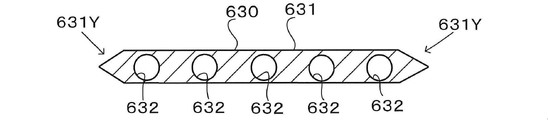
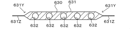
- 2 is a perspective view of the plate of FIG. 1;
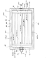
- FIG. The top view of the heat exchanger of 2nd Embodiment.
- FIG. 8 is a cross-sectional view taken along line D8-D8 of FIG. 7;
- FIG. 10 is a cross-sectional view taken along line D10-D10 in FIG.
- FIG. 10 is a diagram relating to a spacer forming step in the method for manufacturing the heat exchanger of FIG. 9;
- FIG. 12 is a diagram of a state in which the spacer base material of FIG. 11 has been cut;
- FIG. 10 is a diagram relating to a spacer attachment step in the method for manufacturing the heat exchanger of FIG. 9;
- FIG. 15 is a cross-sectional view taken along line D15-D15 in FIG. 14; Sectional drawing of the supply member with which the heat exchanger of the modification of 6th Embodiment is provided. Sectional drawing of the supply member with which the heat exchanger of another modification of 6th Embodiment is provided.
- the top view of the supply member with which the heat exchanger of another modification of 6th Embodiment is provided.
- the top view of the state where the supply hose of the modification was connected to the supply member of the heat exchanger of 6th Embodiment.
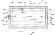
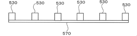
- FIG. 1 is a plan view of a heat exchanger 10 according to this embodiment.
- the heat exchanger 10 is used to cool or heat a heat exchange object via a heat exchange medium. Cooling or warming the heat exchange object includes maintaining the temperature of the heat exchange object within a predetermined temperature range by repeatedly cooling and warming the heat exchange object.
- a heat exchange object is, for example, a battery.
- the battery is, for example, a lithium ion battery.
- heat exchanger 10 is arranged to be interposed between a plurality of cells or modules of a lithium ion battery.
- the heat exchanger 10 is used to keep the temperature of the heat exchange object below a predetermined temperature by cooling the heat exchange object.
- the heat exchange medium is, for example, cooling water or antifreeze.
- the heat exchange medium is hot water, for example.
- the heat exchange medium is cooling water and hot water, for example.
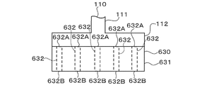
- the heat exchanger 10 is, for example, a pouch type. Therefore, the degree of freedom in shape is enhanced. Moreover, the heat exchanger 10 can be made lightweight. Types of pouches include, for example, a three-side seal type, a four-side seal type, a pillow type, or a gusset type. Heat exchanger 10 includes vessel 20 , supply member 30 , discharge member 40 and plate 50 . In addition, in FIG. 1, components that are originally invisible from the outside are partially indicated by broken lines for reference. Hereinafter, for convenience of explanation, unless otherwise specified, the vertical direction in FIG. It is called height direction.
- the container 20 has an internal space S1 and a peripheral seal portion 90 .
- Container 20 is configured including sheet 21 and sheet 22 .
- the sheets 21 and 22 are heat-sealed and fused together at the outer peripheral portion of the container 20 in plan view, thereby forming a peripheral edge seal portion 90 .
- the inner space S1 of the container 20, which is isolated from the outer space, is formed by the peripheral seal portion 90.
- Perimeter seal 90 defines the perimeter of interior space S ⁇ b>1 of container 20 .
- the mode of heat sealing referred to herein includes modes such as thermal fusion from a heat source and ultrasonic fusion.
- the peripheral seal portion 90 means a portion where the sheets 21 and 22 are fused and integrated.
- the sheets 21 and 22 are composed of resin moldings or films, for example.
- the resin molded product referred to here can be manufactured by methods such as injection molding, pressure molding, vacuum molding, and blow molding, and in-mold molding may be performed to impart design and functionality.
- the type of resin can be polyolefin, polyester, nylon, ABS, and the like.
- the film referred to here is, for example, a resin film that can be produced by a method such as an inflation method or a T-die method, or a laminate of such a resin film on a metal foil.
- the film referred to here may or may not be stretched, and may be a single-layer film or a multilayer film.
- the multilayer film referred to here may be produced by a coating method, may be produced by adhering a plurality of films with an adhesive or the like, or may be produced by a multilayer extrusion method.
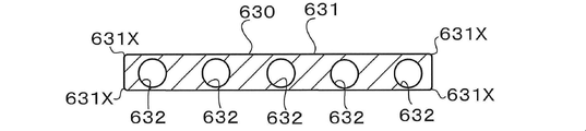
- the sheets 21 and 22 can be configured in various ways, but in this embodiment, the sheets 21 and 22 are composed of the laminate film shown in FIG. 2, for example.
- the laminate film can be a laminate in which a substrate layer 1, an adhesive layer 2, a barrier layer 3, a heat-fusible resin layer 4, and an adhesive layer 5 are laminated.
- the base material layer 1 functions as a base material for the sheets 21 and 22, typically forms the outer layer side of the container 20, and is an insulating resin layer.
- the barrier layer 3 has a function of improving the strength of the sheets 21 and 22 and at least preventing moisture from entering the internal space S1, and is typically a metal layer made of an aluminum alloy foil or the like.
- the heat-sealable resin layer 4 and the adhesive layer 5 are typically made of a heat-sealable resin such as polyolefin, and form the innermost layer of the container 20 .
- a heat-sealable resin such as polyolefin
- the base material layer 1 is a layer provided for the purpose of exhibiting a function as a base material for the sheets 21 and 22 .
- the base material layer 1 is positioned on the outer layer side of the sheets 21 and 22 .
- the material forming the base material layer 1 is not particularly limited as long as it functions as a base material, that is, at least has insulating properties.
- the base material layer 1 can be formed using, for example, a resin, and the resin may contain additives described later.
- the substrate layer 1 may be, for example, a resin film made of resin, or may be formed by applying resin.
- the resin film may be an unstretched film or a stretched film.
- stretched films include uniaxially stretched films and biaxially stretched films, with biaxially stretched films being preferred.
- stretching methods for forming a biaxially stretched film include successive biaxial stretching, inflation, and simultaneous biaxial stretching.
- Methods for applying the resin include a roll coating method, a gravure coating method, an extrusion coating method, and the like.
- resins forming the base material layer 1 include resins such as polyester, polyamide, polyolefin, epoxy resin, acrylic resin, fluororesin, polyurethane, silicon resin, phenolic resin, and modified products of these resins. Further, the resin forming the base material layer 1 may be a copolymer of these resins or a modified product of the copolymer. Furthermore, it may be a mixture of these resins.
- polyesters and polyamides are preferred as resins forming the base material layer 1 .
- polyester examples include polyethylene terephthalate, polybutylene terephthalate, polyethylene naphthalate, polybutylene naphthalate, polyethylene isophthalate, and copolymerized polyester.
- copolyester examples include copolyester having ethylene terephthalate as a main repeating unit.
- copolymer polyester polymerized with ethylene isophthalate with ethylene terephthalate as the main repeating unit hereinafter abbreviated after polyethylene (terephthalate / isophthalate)
- polyethylene (terephthalate / adipate) polyethylene (terephthalate / sodium sulfoisophthalate)
- polyethylene (terephthalate/sodium isophthalate) polyethylene (terephthalate/phenyl-dicarboxylate), polyethylene (terephthalate/decanedicarboxylate), and the like.
- These polyesters may be used singly or in combination of two or more.
- polyamide specifically, aliphatic polyamide such as nylon 6, nylon 66, nylon 610, nylon 12, nylon 46, copolymer of nylon 6 and nylon 66; terephthalic acid and / or isophthalic acid Nylon 6I, nylon 6T, nylon 6IT, nylon 6I6T (I represents isophthalic acid, T represents terephthalic acid) containing structural units derived from hexamethylenediamine-isophthalic acid-terephthalic acid copolymer polyamide, polyamide MXD6 (polymetallic Polyamides containing aromatics such as silylene adipamide); alicyclic polyamides such as polyamide PACM6 (polybis(4-aminocyclohexyl)methane adipamide); Copolymerized polyamides, polyesteramide copolymers and polyetheresteramide copolymers which are copolymers of copolymerized polyamides with polyesters or polyalkylene ether glycols; and polyamides such
- the substrate layer 1 preferably includes at least one of a polyester film, a polyamide film, and a polyolefin film, preferably includes at least one of an oriented polyester film, an oriented polyamide film, and an oriented polyolefin film, More preferably, at least one of an oriented polyethylene terephthalate film, an oriented polybutylene terephthalate film, an oriented nylon film, and an oriented polypropylene film is included, and a biaxially oriented polyethylene terephthalate film, a biaxially oriented polybutylene terephthalate film, and a biaxially oriented nylon film. , biaxially oriented polypropylene film.
- the base material layer 1 may be a single layer, or may be composed of two or more layers.
- the substrate layer 1 may be a laminate obtained by laminating resin films with an adhesive or the like, or may be formed by co-extrusion of resin to form two or more layers. It may also be a laminate of resin films. A laminate of two or more resin films formed by coextrusion of resin may be used as the base material layer 1 without being stretched, or may be used as the base material layer 1 by being uniaxially or biaxially stretched.
- the laminate of two or more resin films in the substrate layer 1 include a laminate of a polyester film and a nylon film, a laminate of nylon films of two or more layers, and a laminate of polyester films of two or more layers. etc., preferably a laminate of a stretched nylon film and a stretched polyester film, a laminate of two or more layers of stretched nylon films, and a laminate of two or more layers of stretched polyester films.
- the substrate layer 1 is a laminate of two layers of resin films, a laminate of polyester resin films and polyester resin films, a laminate of polyamide resin films and polyamide resin films, or a laminate of polyester resin films and polyamide resin films.
- a laminate is preferred, and a laminate of polyethylene terephthalate film and polyethylene terephthalate film, a laminate of nylon film and nylon film, or a laminate of polyethylene terephthalate film and nylon film is more preferred.
- the polyester resin is resistant to discoloration when, for example, an electrolytic solution adheres to the surface. It is preferably located in the outermost layer.
- the two or more layers of resin films may be laminated via an adhesive.
- Preferred adhesives include those similar to those exemplified for the adhesive layer 2 described later.
- the method for laminating two or more layers of resin films is not particularly limited, and known methods can be employed. Examples thereof include dry lamination, sandwich lamination, extrusion lamination, thermal lamination, and the like. A lamination method is mentioned.
- the thickness of the adhesive is, for example, about 2 to 5 ⁇ m.
- an anchor coat layer may be formed on the resin film and laminated.
- the anchor coat layer the same adhesives as those exemplified for the adhesive layer 2 described later can be used. At this time, the thickness of the anchor coat layer is, for example, about 0.01 to 1.0 ⁇ m.
- At least one of the surface and the inside of the substrate layer 1 may contain additives such as lubricants, flame retardants, antiblocking agents, antioxidants, light stabilizers, tackifiers, and antistatic agents. good. Only one type of additive may be used, or two or more types may be mixed and used.
- the surface of the base material layer 1 contains a lubricant.
- the lubricant is not particularly limited, but preferably includes an amide-based lubricant.
- Specific examples of amide lubricants include saturated fatty acid amides, unsaturated fatty acid amides, substituted amides, methylolamides, saturated fatty acid bisamides, unsaturated fatty acid bisamides, fatty acid ester amides, and aromatic bisamides.
- Specific examples of saturated fatty acid amides include lauric acid amide, palmitic acid amide, stearic acid amide, behenic acid amide, and hydroxystearic acid amide.
- unsaturated fatty acid amides include oleic acid amide and erucic acid amide.
- substituted amides include N-oleyl palmitic acid amide, N-stearyl stearic acid amide, N-stearyl oleic acid amide, N-oleyl stearic acid amide, N-stearyl erucic acid amide and the like.
- methylolamide include methylol stearamide.
- saturated fatty acid bisamide examples include methylenebisstearic acid amide, ethylenebiscapric acid amide, ethylenebislauric acid amide, ethylenebisstearic acid amide, ethylenebishydroxystearic acid amide, ethylenebisbehenic acid amide, hexamethylenebisstearin. acid amide, hexamethylenebisbehenamide, hexamethylenehydroxystearic acid amide, N,N'-distearyladipic acid amide, N,N'-distearylsebacic acid amide and the like.
- unsaturated fatty acid bisamides include ethylenebisoleic acid amide, ethylenebiserucic acid amide, hexamethylenebisoleic acid amide, N,N'-dioleyladipic acid amide, and N,N'-dioleylsebacic acid amide. etc.
- fatty acid ester amides include stearamide ethyl stearate.
- aromatic bisamide include m-xylylenebisstearic acid amide, m-xylylenebishydroxystearic acid amide, N,N'-distearylisophthalic acid amide and the like.
- Lubricants may be used singly or in combination of two or more.
- a lubricant exists on the surface of the base material layer 1, its amount is not particularly limited, but is preferably about 3 mg/m 2 or more, more preferably about 4 to 15 mg/m 2 , and still more preferably 5 to 14 mg. / m 2 degree.
- the lubricant present on the surface of the substrate layer 1 may be obtained by exuding the lubricant contained in the resin constituting the substrate layer 1, or by coating the surface of the substrate layer 1 with the lubricant.
- the thickness of the base material layer 1 is not particularly limited as long as it functions as a base material, but it is, for example, about 3 to 50 ⁇ m, preferably about 10 to 35 ⁇ m.
- the thickness of each resin film constituting each layer is preferably about 2 to 25 ⁇ m.
- the adhesive layer 2 is a layer provided between the base layer 1 and the barrier layer 3 as necessary for the purpose of enhancing the adhesiveness between them.
- the adhesive layer 2 is made of an adhesive that can bond the base material layer 1 and the barrier layer 3 together.
- the adhesive used to form the adhesive layer 2 is not limited, but may be any of a chemical reaction type, a solvent volatilization type, a hot melt type, a hot pressure type, and the like. Further, it may be a two-liquid curing adhesive (two-liquid adhesive), a one-liquid curing adhesive (one-liquid adhesive), or a resin that does not involve a curing reaction. Further, the adhesive layer 2 may be a single layer or multiple layers.
- the adhesive component contained in the adhesive include polyesters such as polyethylene terephthalate, polybutylene terephthalate, polyethylene naphthalate, polybutylene naphthalate, polyethylene isophthalate, and copolymerized polyester; polyether; polyurethane; epoxy resin; Phenolic resins; polyamides such as nylon 6, nylon 66, nylon 12, and copolyamides; polyolefin resins such as polyolefins, cyclic polyolefins, acid-modified polyolefins, and acid-modified cyclic polyolefins; polyvinyl acetate; cellulose; (meth)acrylic resins; polyimide; polycarbonate; amino resin such as urea resin and melamine resin; rubber such as chloroprene rubber, nitrile rubber and styrene-butadiene rubber; These adhesive components may be used singly or in combination of two or more.
- polyurethane adhesives are preferred.
- an appropriate curing agent can be used in combination with these adhesive component resins to increase the adhesive strength.
- the curing agent is selected from among polyisocyanates, polyfunctional epoxy resins, oxazoline group-containing polymers, polyamine resins, acid anhydrides, etc., depending on the functional groups of the adhesive component.
- polyurethane adhesives examples include polyurethane adhesives containing a main agent containing a polyol compound and a curing agent containing an isocyanate compound.
- Preferred examples include a two-pack curable polyurethane adhesive that uses a polyol such as polyester polyol, polyether polyol, and acrylic polyol as a main component and an aromatic or aliphatic polyisocyanate as a curing agent.
- a polyol compound it is preferable to use a polyester polyol having a hydroxyl group in a side chain in addition to the terminal hydroxyl group of the repeating unit.
- the adhesive layer 2 is formed of a polyurethane adhesive, the sheets 21 and 22 are provided with excellent resistance to the electrolyte solution, and even if the electrolyte solution adheres to the side surfaces, the peeling of the base layer 1 is suppressed.
- the adhesive layer 2 may contain other components as long as they do not impede adhesion, and may contain colorants, thermoplastic elastomers, tackifiers, fillers, and the like. Since the adhesive layer 2 contains a coloring agent, the sheets 21 and 22 can be colored. Known substances such as pigments and dyes can be used as the colorant. In addition, only one type of colorant may be used, or two or more types may be mixed and used.
- the type of pigment is not particularly limited as long as it does not impair the adhesiveness of the adhesive layer 2.
- organic pigments include azo-based, phthalocyanine-based, quinacridone-based, anthraquinone-based, dioxazine-based, indigothioindigo-based, perinone-perylene-based, isoindolenine-based, and benzimidazolone-based pigments.
- pigments include carbon black, titanium oxide, cadmium, lead, chromium oxide, and iron pigments, as well as fine powder of mica and fish scale foil.
- coloring agents for example, carbon black is preferable in order to make the appearance of the sheets 21 and 22 black.
- the average particle size of the pigment is not particularly limited, and is, for example, about 0.05 to 5 ⁇ m, preferably about 0.08 to 2 ⁇ m.
- the average particle size of the pigment is the median size measured with a laser diffraction/scattering particle size distribution analyzer.
- the pigment content in the adhesive layer 2 is not particularly limited as long as the sheets 21 and 22 are colored, and is, for example, about 5 to 60% by mass, preferably 10 to 40% by mass.
- the thickness of the adhesive layer 2 is not particularly limited as long as the substrate layer 1 and the barrier layer 3 can be adhered, but is, for example, about 1 ⁇ m or more, or about 2 ⁇ m or more. Moreover, the thickness of the adhesive layer 2 is, for example, about 10 ⁇ m or less, or about 5 ⁇ m or less. Preferred ranges for the thickness of the adhesive layer 2 include about 1 to 10 ⁇ m, about 1 to 5 ⁇ m, about 2 to 10 ⁇ m, and about 2 to 5 ⁇ m.
- the colored layer is a layer provided as necessary between the base layer 1 and the barrier layer 3 (not shown).
- a colored layer may be provided between the base material layer 1 and the adhesive layer 2 and between the adhesive layer 2 and the barrier layer 3 . Further, a colored layer may be provided outside the base material layer 1 . By providing a colored layer, the sheets 21 and 22 can be colored.
- the colored layer can be formed, for example, by applying ink containing a coloring agent to the surface of the base material layer 1 or the surface of the barrier layer 3 .
- a coloring agent such as pigments and dyes can be used as the colorant.
- only one type of colorant may be used, or two or more types may be mixed and used.
- colorant contained in the colored layer are the same as those exemplified in the [Adhesive layer 2] column.
- the barrier layer 3 is a layer that prevents at least moisture from entering.
- the barrier layer 3 examples include a metal foil, vapor deposition film, and resin layer having barrier properties.
- vapor-deposited films include metal vapor-deposited films, inorganic oxide vapor-deposited films, and carbon-containing inorganic oxide vapor-deposited films.
- the barrier layer 3 may also include a resin film provided with at least one of these deposited films and a resin layer.
- a plurality of barrier layers 3 may be provided.
- the barrier layer 3 preferably includes a layer made of a metal material. Specific examples of the metal material constituting the barrier layer 3 include aluminum alloys, stainless steels, titanium steels, and steel plates. When used as metal foils, at least one of aluminum alloy foils and stainless steel foils is included. is preferred.
- the aluminum alloy foil is more preferably a soft aluminum alloy foil made of, for example, an annealed aluminum alloy. , an aluminum alloy foil containing iron.
- the iron content is preferably 0.1 to 9.0% by mass, more preferably 0.5 to 2.0% by mass.
- the iron content is 0.1% by mass or more, sheets 21 and 22 having better formability can be obtained.
- the iron content is 9.0% by mass or less, the sheets 21 and 22 with more excellent flexibility can be obtained.
- the soft aluminum alloy foil for example, an aluminum alloy having a composition specified by JIS H4160: 1994 A8021H-O, JIS H4160: 1994 A8079H-O, JIS H4000: 2014 A8021P-O, or JIS H4000: 2014 A8079P-O foil.
- silicon, magnesium, copper, manganese, etc. may be added as needed.
- softening can be performed by annealing treatment or the like.
- stainless steel foils include austenitic, ferritic, austenitic/ferritic, martensitic, and precipitation hardened stainless steel foils. Furthermore, from the viewpoint of providing the sheets 21 and 22 with excellent moldability, the stainless steel foil is preferably made of austenitic stainless steel.
- austenitic stainless steel that constitutes the stainless steel foil
- SUS304 is particularly preferable.
- the thickness of the barrier layer 3 should be at least as long as it functions as a barrier layer that suppresses the intrusion of moisture.
- the thickness of the barrier layer 3 is preferably about 85 ⁇ m or less, more preferably about 50 ⁇ m or less, even more preferably about 40 ⁇ m or less, particularly preferably about 35 ⁇ m or less.
- the thickness of the barrier layer 3 is preferably about 10 ⁇ m or more, more preferably about 20 ⁇ m or more, and more preferably about 25 ⁇ m or more.
- Preferred ranges for the thickness are about 10 to 85 ⁇ m, about 10 to 50 ⁇ m, about 10 to 40 ⁇ m, about 10 to 35 ⁇ m, about 20 to 85 ⁇ m, about 20 to 50 ⁇ m, about 20 to 40 ⁇ m, about 20 to 35 ⁇ m, 25 to about 85 ⁇ m, about 25 to 50 ⁇ m, about 25 to 40 ⁇ m, and about 25 to 35 ⁇ m.
- the barrier layer 3 is made of an aluminum alloy foil, the above range is particularly preferred.
- the thickness of the stainless steel foil is preferably about 60 ⁇ m or less, more preferably about 50 ⁇ m or less, even more preferably about 40 ⁇ m or less, and even more preferably about 40 ⁇ m or less. 30 ⁇ m or less, particularly preferably about 25 ⁇ m or less.
- the thickness of the stainless steel foil is preferably about 10 ⁇ m or more, more preferably about 15 ⁇ m or more.
- the preferable range of the thickness of the stainless steel foil is about 10 to 60 ⁇ m, about 10 to 50 ⁇ m, about 10 to 40 ⁇ m, about 10 to 30 ⁇ m, about 10 to 25 ⁇ m, about 15 to 60 ⁇ m, about 15 to 50 ⁇ m, About 15 to 40 ⁇ m, about 15 to 30 ⁇ m, and about 15 to 25 ⁇ m can be mentioned.
- the barrier layer 3 is a metal foil, it is preferable that at least the surface opposite to the base layer is provided with a corrosion-resistant film in order to prevent dissolution and corrosion.
- the barrier layer 3 may be provided with a corrosion resistant coating on both sides.
- the corrosion-resistant film includes, for example, hydrothermal transformation treatment such as boehmite treatment, chemical conversion treatment, anodizing treatment, plating treatment such as nickel and chromium, and corrosion prevention treatment such as applying a coating agent to the surface of the barrier layer.
- a thin film that provides corrosion resistance to the barrier layer As the treatment for forming the corrosion-resistant film, one type may be performed, or two or more types may be used in combination. Also, not only one layer but also multiple layers can be used.
- the hydrothermal transformation treatment and the anodizing treatment are treatments in which the surface of the metal foil is dissolved by a treatment agent to form a metal compound having excellent corrosion resistance. These treatments are sometimes included in the definition of chemical conversion treatment.
- the barrier layer 3 has a corrosion-resistant film, the barrier layer 3 includes the corrosion-resistant film.
- the corrosion-resistant coating prevents delamination between the barrier layer (e.g., aluminum alloy foil) and the substrate layer during molding of the sheets 21 and 22, and the hydrogen fluoride generated by the reaction between the electrolyte and moisture. It prevents the dissolution and corrosion of the barrier layer surface, especially dissolution and corrosion of aluminum oxide present on the barrier layer surface when the barrier layer is an aluminum alloy foil, and improves the adhesion (wettability) of the barrier layer surface. It shows the effect of preventing delamination between the base material layer and the barrier layer during heat sealing and preventing delamination between the base material layer and the barrier layer during molding.
- the barrier layer e.g., aluminum alloy foil
- corrosion-resistant coatings formed by chemical conversion treatment are known, and are mainly composed of at least one of phosphates, chromates, fluorides, triazinethiol compounds, and rare earth oxides. and corrosion-resistant coatings containing.
- Examples of chemical conversion treatments using phosphate and chromate include chromic acid chromate treatment, phosphoric acid chromate treatment, phosphoric acid-chromate treatment, and chromate treatment.
- Examples of compounds include chromium nitrate, chromium fluoride, chromium sulfate, chromium acetate, chromium oxalate, chromium biphosphate, chromium acetyl acetate, chromium chloride, potassium chromium sulfate, and the like.
- Phosphorus compounds used for these treatments include sodium phosphate, potassium phosphate, ammonium phosphate, polyphosphoric acid, and the like.
- Examples of the chromate treatment include etching chromate treatment, electrolytic chromate treatment, coating-type chromate treatment, etc., and coating-type chromate treatment is preferred.
- the inner layer side surface of the barrier layer (for example, aluminum alloy foil) is first subjected to a well-known method such as an alkali immersion method, an electrolytic cleaning method, an acid cleaning method, an electrolytic acid cleaning method, an acid activation method, or the like.
- metal phosphate such as Cr (chromium) phosphate, Ti (titanium) phosphate, Zr (zirconium) phosphate, Zn (zinc) phosphate is applied to the degreased surface.
- This is a treatment in which a treatment liquid comprising a mixture is applied by a well-known coating method such as a roll coating method, a gravure printing method, or an immersion method, and then dried.
- Various solvents such as water, alcohol-based solvents, hydrocarbon-based solvents, ketone-based solvents, ester-based solvents, and ether-based solvents can be used as the treatment liquid, and water is preferred.
- the resin component used at this time includes polymers such as phenolic resins and acrylic resins. and the chromate treatment used.
- the repeating units represented by the following general formulas (1) to (4) may be contained singly or in any combination of two or more. good too.
- the acrylic resin is polyacrylic acid, acrylic acid methacrylic acid ester copolymer, acrylic acid maleic acid copolymer, acrylic acid styrene copolymer, or derivatives thereof such as sodium salts, ammonium salts, and amine salts. is preferred.
- derivatives of polyacrylic acid such as ammonium salt, sodium salt or amine salt of polyacrylic acid are preferred.
- polyacrylic acid means a polymer of acrylic acid.
- the acrylic resin is preferably a copolymer of acrylic acid and dicarboxylic acid or dicarboxylic anhydride, and the ammonium salt, sodium salt, Alternatively, it is preferably an amine salt. Only one type of acrylic resin may be used, or two or more types may be mixed and used.
- X represents a hydrogen atom, hydroxy group, alkyl group, hydroxyalkyl group, allyl group or benzyl group.
- R 1 and R 2 are the same or different and represent a hydroxy group, an alkyl group, or a hydroxyalkyl group.
- alkyl groups represented by X, R 1 and R 2 in general formulas (1) to (4) include methyl group, ethyl group, n-propyl group, isopropyl group, n-butyl group, isobutyl group, A linear or branched alkyl group having 1 to 4 carbon atoms such as a tert-butyl group can be mentioned.
- hydroxyalkyl groups represented by X, R 1 and R 2 include hydroxymethyl group, 1-hydroxyethyl group, 2-hydroxyethyl group, 1-hydroxypropyl group, 2-hydroxypropyl group, 3- A straight or branched chain having 1 to 4 carbon atoms substituted with one hydroxy group such as hydroxypropyl group, 1-hydroxybutyl group, 2-hydroxybutyl group, 3-hydroxybutyl group and 4-hydroxybutyl group An alkyl group is mentioned.
- the alkyl groups and hydroxyalkyl groups represented by X, R 1 and R 2 may be the same or different.
- X is preferably a hydrogen atom, a hydroxy group or a hydroxyalkyl group.
- the number average molecular weight of the aminated phenol polymer having repeating units represented by formulas (1) to (4) is, for example, preferably about 500 to 1,000,000, more preferably about 1,000 to 20,000. more preferred.
- the aminated phenol polymer is produced, for example, by polycondensing a phenol compound or naphthol compound and formaldehyde to produce a polymer comprising repeating units represented by the general formula (1) or general formula (3), followed by formaldehyde. and an amine (R 1 R 2 NH) to introduce a functional group (--CH 2 NR 1 R 2 ) into the polymer obtained above.
- An aminated phenol polymer is used individually by 1 type or in mixture of 2 or more types.
- the corrosion-resistant film is formed by a coating-type corrosion prevention treatment in which a coating agent containing at least one selected from the group consisting of rare earth element oxide sol, anionic polymer, and cationic polymer is applied.
- a thin film that is The coating agent may further contain phosphoric acid or a phosphate, a cross-linking agent for cross-linking the polymer.
- rare earth element oxide sol rare earth element oxide fine particles (for example, particles having an average particle size of 100 nm or less) are dispersed in a liquid dispersion medium.
- rare earth element oxides include cerium oxide, yttrium oxide, neodymium oxide, and lanthanum oxide, and cerium oxide is preferable from the viewpoint of further improving adhesion.
- the rare earth element oxides contained in the corrosion-resistant coating can be used singly or in combination of two or more.
- various solvents such as water, alcohol solvents, hydrocarbon solvents, ketone solvents, ester solvents, and ether solvents can be used, with water being preferred.
- the cationic polymer include polyethyleneimine, an ionic polymer complex composed of a polymer containing polyethyleneimine and carboxylic acid, a primary amine-grafted acrylic resin obtained by graft-polymerizing a primary amine to an acrylic backbone, polyallylamine, or a derivative thereof. , aminated phenols and the like are preferred.
- the anionic polymer is preferably poly(meth)acrylic acid or a salt thereof, or a copolymer containing (meth)acrylic acid or a salt thereof as a main component.
- the cross-linking agent is preferably at least one selected from the group consisting of a compound having a functional group such as an isocyanate group, a glycidyl group, a carboxyl group, or an oxazoline group, and a silane coupling agent.
- the phosphoric acid or phosphate is preferably condensed phosphoric acid or condensed phosphate.
- fine particles of metal oxides such as aluminum oxide, titanium oxide, cerium oxide, and tin oxide, and barium sulfate are dispersed in phosphoric acid, which is applied to the surface of the barrier layer. C. or higher and formed by baking.
- the corrosion-resistant coating may, if necessary, have a laminated structure in which at least one of a cationic polymer and an anionic polymer is further laminated.
- a cationic polymer and anionic polymers include those described above.
- the analysis of the composition of the corrosion-resistant coating can be performed using, for example, time-of-flight secondary ion mass spectrometry.
- the amount of the corrosion - resistant film formed on the surface of the barrier layer 3 in the chemical conversion treatment is not particularly limited. is about 0.5 to 50 mg, preferably about 1.0 to 40 mg in terms of chromium, the phosphorus compound is about 0.5 to 50 mg, preferably about 1.0 to 40 mg in terms of phosphorus, and aminated phenol polymer is contained in a proportion of, for example, about 1.0 to 200 mg, preferably about 5.0 to 150 mg.
- the thickness of the corrosion-resistant coating is not particularly limited, but is preferably about 1 nm to 20 ⁇ m, more preferably 1 nm to 100 nm, from the viewpoint of cohesion of the coating and adhesion to the barrier layer and the heat-sealable resin layer. about 1 nm to 50 nm, more preferably about 1 nm to 50 nm.
- the thickness of the corrosion-resistant film can be measured by observation with a transmission electron microscope, or by a combination of observation with a transmission electron microscope and energy dispersive X-ray spectroscopy or electron beam energy loss spectroscopy.
- secondary ions composed of Ce, P and O for example, at least one of Ce 2 PO 4 + and CePO 4 ⁇ species
- secondary ions composed of Cr, P, and O eg, at least one of CrPO 2 + and CrPO 4 ⁇
- Chemical conversion treatment involves applying a solution containing a compound used to form a corrosion-resistant film to the surface of the barrier layer by a bar coating method, roll coating method, gravure coating method, immersion method, etc., and then changing the temperature of the barrier layer. is carried out by heating so that the temperature is about 70 to 200°C.
- the barrier layer may be previously subjected to a degreasing treatment by an alkali immersion method, an electrolytic cleaning method, an acid cleaning method, an electrolytic acid cleaning method, or the like. By performing the degreasing treatment in this way, it becomes possible to perform the chemical conversion treatment on the surface of the barrier layer more efficiently.
- the heat-fusible resin layer 4 corresponds to the innermost layer, and the heat-fusible resin layers are heat-fused to seal the plate 50 when the heat exchanger 10 is manufactured. It is a layer (sealant layer) that exhibits its function.
- the heat-fusible resin layer 4 contains polypropylene and polyethylene.
- a sea-island structure is observed in a cross-sectional image of the heat-fusible resin layer 4 taken in the direction parallel to the TD and in the thickness direction y using a scanning electron microscope. .
- Propylene includes homopolypropylene, block copolymers of polypropylene (e.g. block copolymers of propylene and ethylene, block copolymers of propylene and butene, block copolymers of propylene, ethylene and butene, preferably block copolymers of propylene and ethylene), polypropylene. (e.g. random copolymers of propylene and ethylene, random copolymers of propylene and butene, random copolymers of propylene, ethylene and butene, preferably random copolymers of propylene and ethylene), propylene-alpha olefin copolymers, etc. mentioned.
- block copolymers of polypropylene e.g. block copolymers of propylene and ethylene, block copolymers of propylene and butene, block copolymers of propylene, ethylene and butene, preferably block copolymers of propylene and ethylene
- Ethylene includes low-density polyethylene, medium-density polyethylene, high-density polyethylene, linear low-density polyethylene, ethylene- ⁇ -olefin copolymer, and the like.
- the polypropylene and polyethylene contained in the heat-fusible resin layer 4 may be of one type, or may be of two or more types.
- the heat-fusible resin layer 4 is preferably made of a polypropylene resin composition containing 45% by mass or less of polyethylene.
- the polyethylene content is, for example, about 45% by mass or less, preferably about 30% by mass or less, more preferably about 20% by mass or less, and preferably about 5% by mass or more, more preferably about 10% by mass or more.
- a preferred range is about 5 to 45% by mass, about 5 to 30% by mass, about 5 to 20% by mass, about 10 to 45% by mass, about 10 to 30% by mass, and about 10 to 20% by mass. mentioned.
- the content rate of polypropylene is 95 mass % or less and 90 mass % or less, for example.
- the content rate of polypropylene is 55 mass % or more, 70 mass % or more, and 80 mass % or more, for example.
- the preferred range of polypropylene content is about 55 to 95% by mass, about 70 to 95% by mass, about 80 to 95% by mass, about 55 to 90% by mass, about 70 to 90% by mass, and 80 to 90% by mass. degree.
- the mass ratio of polypropylene and polyethylene in the polypropylene resin composition is preferably about 5 to 80 parts by mass, more preferably about 5 to 45 parts by mass, more preferably about 10 parts by mass with respect to 100 parts by mass of polypropylene. up to about 30 parts by mass.
- the heat-fusible resin layer 4 may contain other resins in addition to polypropylene and polyethylene.
- Other resins include, for example, acid-modified polyolefins.
- Acid-modified polyolefin is a polymer modified by block polymerization or graft polymerization of polyolefin with an acid component.
- acid-modified polyolefins include polyethylenes such as low-density polyethylene, medium-density polyethylene, high-density polyethylene, and linear low-density polyethylene; ethylene- ⁇ -olefin copolymers; homopolypropylene and block copolymers of polypropylene ( propylene- ⁇ -olefin copolymers; ethylene-butene-propylene terpolymers; and the like.
- polypropylene is preferred.
- the polyolefin resin is a copolymer, it may be a block copolymer or a random copolymer. These polyolefin-based resins may be used alone or in combination of two or more.
- acid-modified polyolefin a copolymer obtained by copolymerizing a polar molecule such as acrylic acid or methacrylic acid with the above polyolefin, or a polymer such as crosslinked polyolefin can be used.
- acid components used for acid modification include carboxylic acids such as maleic acid, acrylic acid, itaconic acid, crotonic acid, maleic anhydride and itaconic anhydride, and anhydrides thereof.
- the acid-modified polyolefin may be an acid-modified cyclic polyolefin.
- Acid-modified cyclic polyolefin is a polymer obtained by copolymerizing a part of the monomers constituting the cyclic polyolefin in place of the acid component, or by block-polymerizing or graft-polymerizing the acid component to the cyclic polyolefin. be.
- the acid-modified cyclic polyolefin is the same as described above.
- the acid component used for acid modification is the same as the acid component used for modification of polyolefin.
- Preferable acid-modified polyolefins include polyolefins modified with carboxylic acid or its anhydride, polypropylene modified with carboxylic acid or its anhydride, maleic anhydride-modified polyolefin, and maleic anhydride-modified polypropylene.
- the heat-fusible resin layer 4 may be formed of only one layer, or may be formed of two or more layers of the same or different resins.
- the heat-fusible resin layer 4 may contain a lubricant or the like as necessary.
- a lubricant is not particularly limited, and known lubricants can be used. Lubricants may be used singly or in combination of two or more.
- the lubricant is not particularly limited, but preferably includes an amide-based lubricant. Specific examples of the lubricant include those exemplified for the base material layer 1 . Lubricants may be used singly or in combination of two or more.
- the amount of the lubricant is not particularly limited, but from the viewpoint of improving the moldability of the sheets 21 and 22, it is preferably about 10 to 50 mg/m 2 , More preferably, it is about 15 to 40 mg/m 2 .
- the lubricant present on the surface of the heat-fusible resin layer 4 may be obtained by exuding the lubricant contained in the resin constituting the heat-fusible resin layer 4 .
- the surface may be coated with a lubricant.
- the thickness of the heat-fusible resin layer 4 is not particularly limited as long as the heat-fusible resin layers are heat-sealed to each other to exhibit the function of sealing the plate 50, but for example, about 100 ⁇ m or less, preferably about 85 ⁇ m or less, more preferably about 15 to 85 ⁇ m.
- the thickness of the heat-fusible resin layer 4 is preferably about 85 ⁇ m or less, more preferably about 15 to 45 ⁇ m.
- the thickness of the heat-fusible resin layer 4 is preferably about 20 ⁇ m or more, more preferably 35 to 85 ⁇ m. degree.
- the heat-fusible resin layer 4 is preferably formed by melt extrusion molding. Moreover, when it has the adhesive layer 5 mentioned later, it is preferable that the adhesive layer 5 and the heat-fusible resin layer 4 are formed by melt co-extrusion molding. In the present embodiment, it is preferable to suppress the crystal growth of polyethylene in polypropylene by setting the cooling condition of the molten resin forming the heat-fusible resin layer 4 to a rapid cooling condition. When the adhesive layer 5 and the heat-fusible resin layer 4 are formed by melt co-extrusion molding, the thickness of the adhesive layer 5 is set to 15 to 45 ⁇ m, and the thickness of the heat-fusible resin layer 4 is set to 15 to 45 ⁇ m. is preferred.
- Adhesion layer In the sheets 21 and 22 of the present embodiment, the adhesive layer 5 is optionally provided between the barrier layer 3 (or acid-resistant film) and the heat-fusible resin layer 4 in order to firmly bond them. layer.
- the adhesive layer 5 is made of a resin capable of bonding the barrier layer 3 and the heat-fusible resin layer 4 together.
- the resin used for forming the adhesive layer 5 for example, the same adhesives as those exemplified for the adhesive layer 2 can be used.
- the resin used to form the adhesive layer 5 preferably contains a polyolefin skeleton, and includes the polyolefins and acid-modified polyolefins exemplified for the heat-fusible resin layer 4 described above. Whether the resin constituting the adhesive layer 5 contains a polyolefin skeleton can be analyzed by, for example, infrared spectroscopy, gas chromatography mass spectrometry, or the like, and the analysis method is not particularly limited.
- the resin forming the adhesive layer 5 is analyzed by infrared spectroscopy, it is preferable that a peak derived from maleic anhydride is detected.
- a peak derived from maleic anhydride is detected near wavenumbers of 1760 cm ⁇ 1 and 1780 cm ⁇ 1 .
- the peak may be too small to be detected. In that case, it can be analyzed by nuclear magnetic resonance spectroscopy.
- the adhesive layer 5 preferably contains an acid-modified polyolefin.
- acid-modified polyolefins are polyolefins modified with carboxylic acid or its anhydride, polypropylene modified with carboxylic acid or its anhydride, maleic anhydride-modified polyolefin, and maleic anhydride-modified polypropylene.
- the adhesive layer 5 is made of a cured resin composition containing an acid-modified polyolefin and a curing agent. It is more preferable to be a thing.
- Preferred examples of the acid-modified polyolefin include those mentioned above.
- the adhesive layer 5 is a cured product of a resin composition containing acid-modified polyolefin and at least one selected from the group consisting of a compound having an isocyanate group, a compound having an oxazoline group, and a compound having an epoxy group.
- a cured product of a resin composition containing an acid-modified polyolefin and at least one selected from the group consisting of a compound having an isocyanate group and a compound having an epoxy group is particularly preferred.
- the adhesive layer 5 preferably contains at least one selected from the group consisting of polyurethane, polyester, and epoxy resin, and more preferably contains polyurethane and epoxy resin.
- the polyester for example, an amide ester resin is preferable.
- Amide ester resins are generally produced by the reaction of carboxyl groups and oxazoline groups. More preferably, the adhesive layer 5 is a cured product of a resin composition containing at least one of these resins and the acid-modified polyolefin.
- the adhesive layer 5 contains an isocyanate group-containing compound, an oxazoline group-containing compound, or an unreacted product of a curing agent such as an epoxy resin
- the presence of the unreacted product can be detected by, for example, infrared spectroscopy, It can be confirmed by a method selected from Raman spectroscopy, time-of-flight secondary ion mass spectrometry (TOF-SIMS), and the like.
- the adhesive layer 5 contains at least one selected from the group consisting of oxygen atoms, heterocycles, C ⁇ N bonds, and C—O—C bonds It is preferably a cured product of a resin composition containing one curing agent.
- the curing agent having a heterocyclic ring includes, for example, a curing agent having an oxazoline group, a curing agent having an epoxy group, and the like.
- the curing agent having a C ⁇ N bond includes a curing agent having an oxazoline group, a curing agent having an isocyanate group, and the like.
- curing agents having a C—O—C bond include curing agents having an oxazoline group, curing agents having an epoxy group, and polyurethanes.
- the adhesive layer 5 is a cured product of a resin composition containing these curing agents, for example, gas chromatography mass spectrometry (GCMS), infrared spectroscopy (IR), time-of-flight secondary ion mass spectrometry (TOF -SIMS) and X-ray photoelectron spectroscopy (XPS).
- GCMS gas chromatography mass spectrometry
- IR infrared spectroscopy
- TOF -SIMS time-of-flight secondary ion mass spectrometry
- XPS X-ray photoelectron spectroscopy
- the compound having an isocyanate group is not particularly limited, but from the viewpoint of effectively increasing the adhesion between the barrier layer 3 and the adhesive layer 5, polyfunctional isocyanate compounds are preferred.
- the polyfunctional isocyanate compound is not particularly limited as long as it is a compound having two or more isocyanate groups.
- Specific examples of polyfunctional isocyanate curing agents include pentane diisocyanate (PDI), isophorone diisocyanate (IPDI), hexamethylene diisocyanate (HDI), tolylene diisocyanate (TDI), diphenylmethane diisocyanate (MDI), polymerization and nurate compounds, mixtures thereof, copolymers with other polymers, and the like.
- adducts, burettes, isocyanurates and the like are included.
- the content of the compound having an isocyanate group in the adhesive layer 5 is preferably in the range of 0.1 to 50% by mass, more preferably 0.5 to 40% by mass in the resin composition constituting the adhesive layer 5. A range is more preferred. Thereby, the adhesion between the barrier layer 3 and the adhesive layer 5 can be effectively improved.
- the compound having an oxazoline group is not particularly limited as long as it is a compound having an oxazoline skeleton.
- Specific examples of compounds having an oxazoline group include those having a polystyrene main chain and those having an acrylic main chain.
- the Epocross series by Nippon Shokubai Co., Ltd. etc. are mentioned, for example.
- the ratio of the compound having an oxazoline group in the adhesive layer 5 is preferably in the range of 0.1 to 50% by mass, more preferably 0.5 to 40% by mass, in the resin composition constituting the adhesive layer 5. is more preferable. Thereby, the adhesion between the barrier layer 3 and the adhesive layer 5 can be effectively improved.
- Examples of compounds having an epoxy group include epoxy resins.
- the epoxy resin is not particularly limited as long as it is a resin capable of forming a crosslinked structure with epoxy groups present in the molecule, and known epoxy resins can be used.
- the weight average molecular weight of the epoxy resin is preferably about 50 to 2000, more preferably about 100 to 1000, still more preferably about 200 to 800.
- the weight average molecular weight of the epoxy resin is a value measured by gel permeation chromatography (GPC) under conditions using polystyrene as a standard sample.
- epoxy resins include glycidyl ether derivatives of trimethylolpropane, bisphenol A diglycidyl ether, modified bisphenol A diglycidyl ether, novolac glycidyl ether, glycerin polyglycidyl ether, and polyglycerin polyglycidyl ether.
- An epoxy resin may be used individually by 1 type, and may be used in combination of 2 or more types.
- the proportion of the epoxy resin in the adhesive layer 5 is preferably in the range of 0.1 to 50% by mass, more preferably in the range of 0.5 to 40% by mass, in the resin composition constituting the adhesive layer 5. is more preferred. Thereby, the adhesion between the barrier layer 3 and the adhesive layer 5 can be effectively improved.
- the polyurethane is not particularly limited, and known polyurethanes can be used.
- the adhesive layer 5 may be, for example, a cured product of two-component curing type polyurethane.
- the proportion of polyurethane in the adhesive layer 5 is preferably in the range of 0.1 to 50% by mass, more preferably in the range of 0.5 to 40% by mass, in the resin composition constituting the adhesive layer 5. more preferred.
- the adhesion between the barrier layer 3 and the adhesive layer 5 can be effectively enhanced in an atmosphere containing a component that induces corrosion of the barrier layer, such as an electrolytic solution.
- the adhesive layer 5 is a cured product of a resin composition containing at least one selected from the group consisting of a compound having an isocyanate group, a compound having an oxazoline group, and an epoxy resin, and the acid-modified polyolefin.
- the acid-modified polyolefin functions as a main agent, and the compound having an isocyanate group, the compound having an oxazoline group, and the compound having an epoxy group each function as a curing agent.
- the thickness of the adhesive layer 5 is preferably about 50 ⁇ m or less, about 45 ⁇ m or less, about 30 ⁇ m or less, about 20 ⁇ m or less, or about 5 ⁇ m or less.
- the thickness of the adhesive layer 5 is preferably about 0.1 ⁇ m or more, about 0.5 ⁇ m or more, about 5 ⁇ m or more, about 10 ⁇ m or more, or about 15 ⁇ m or more.
- the thickness range is preferably about 0.1 to 50 ⁇ m, about 0.1 to 45 ⁇ m, about 0.1 to 30 ⁇ m, about 0.1 to 20 ⁇ m, about 0.1 to 5 ⁇ m, 0.5 to About 50 ⁇ m, about 0.5 to 45 ⁇ m, about 0.5 to 30 ⁇ m, about 0.5 to 20 ⁇ m, about 0.5 to 5 ⁇ m, about 5 to 50 ⁇ m, about 5 to 45 ⁇ m, about 5 to 30 ⁇ m, about 5 to 20 ⁇ m , about 10-50 ⁇ m, about 10-45 ⁇ m, about 10-30 ⁇ m, about 10-20 ⁇ m, about 15-50 ⁇ m, about 15-45 ⁇ m, about 15-30 ⁇ m, about 15-20 ⁇ m.
- the thickness is preferably about 1 to 10 ⁇ m, more preferably about 1 to 5 ⁇ m. be done.
- a resin (acid-modified polyolefin, etc.) exemplified for the heat-fusible resin layer 4 it is preferably about 5 to 50 ⁇ m, about 5 to 45 ⁇ m, about 10 to 50 ⁇ m, about 10 to 45 ⁇ m, About 15 to 50 ⁇ m and about 15 to 45 ⁇ m can be mentioned.
- the adhesive layer 5 is the adhesive exemplified for the adhesive layer 2 or a cured product of a resin composition containing an acid-modified polyolefin and a curing agent, for example, the resin composition is applied and cured by heating or the like.
- the adhesive layer 5 can be formed.
- the resins exemplified for the heat-fusible resin layer 4 for example, the heat-fusible resin layer 4 and the adhesive layer 5 can be suitably formed by melt co-extrusion molding.
- the material constituting the adhesive layer 5 is not limited to this.
- a resin having a high glass transition point or a high melting point can be selected as the material forming the adhesive layer 5 from the viewpoint of heat resistance.
- a material that can be bonded to the plate 50 can be selected as the material forming the adhesive layer 5 .
- the container 20 of this embodiment has a shape as shown in FIG. Manufactured by heat-sealing along.
- the seat 22 includes an angular ring-shaped flange portion 22A corresponding to an outer peripheral portion in plan view, and a formed portion 22B that is continuous with the inner edge of the flange portion 22A and bulges upward therefrom.
- the sheets 21, 22 are superimposed so that their outer edges are coincident. In this state, a predetermined range including the outer edge of the sheet 21 and the flange portion 22A of the sheet 22 are heat-sealed so as to be integrated, thereby forming the peripheral edge seal portion 90 .
- the peripheral edge seal portion 90 extends over the entire outer circumference of the container 20 and is formed in an angular annular shape.
- the sheet 21 may be tray-shaped and the sheet 22 may be flat, or both the sheets 21 and 22 may be tray-shaped.
- the heat exchange medium is taken out by breaking the portion of the sheets 21 and 22 including the peripheral edge seal portion 90 so that the internal space S1 is opened. , can extinguish the heat exchange object.
- the supply member 30 is attached to the container 20 so as to communicate the internal space S1 with the outside.
- the supply member 30 is, for example, a spout.
- Feed member 30 has an inlet 31 and an outlet 32 .
- Inlet 31 is located outside container 20 .
- the outlet 32 is located in the interior space S1.
- a supply hose 110 is attached to the inlet 31 to supply the heat exchange medium to the vessel 20 .
- the heat exchange medium supplied by the supply hose 110 passes through the inlet 31 and the outlet 32 of the supply member 30 and flows into the internal space S1.
- the discharge member 40 is attached to the container 20 so as to communicate the internal space S1 with the outside.
- the ejection member 40 is, for example, a spout.
- Evacuation member 40 has an inlet 41 and an outlet 42 .
- the entrance 41 is located in the internal space S1.
- Outlet 42 is located outside container 20 .
- a discharge hose 120 is attached to the outlet 42 for discharging the heat exchange medium from the vessel 20 .
- the heat exchange medium that has passed through the internal space S1 passes through the inlet 41 and outlet 42 of the discharge member 40 and flows to the discharge hose 120 .
- the material forming the supply member 30 and the discharge member 40 is, for example, synthetic resin or metal.
- Synthetic resins include, for example, polyesters, polyolefins, polyamides, polyimides, polymethyltempene, polyphenylene oxides, polysulfones, polyethersulfones, polyphenylsulfones, polyarylates, polyetheretherketones, polyphenylenesulfides, fluororesins, polyarylates, etc. is.
- Polyolefin specifically includes medium-density polyethylene, high-density polyethylene, linear low-density polyethylene, ethylene- ⁇ -olefin copolymer, polypropylene, polybutene, polyisobutene, polyisobutylene, polybutadiene, polyisoprene, and ethylene-methacryl. They include acid copolymers, copolymers of ethylene and unsaturated carboxylic acid such as ethylene-acrylic acid copolymers, and the like. Examples of metals include aluminum alloys, copper alloys, stainless steels, titanium steels, and steel plates.
- the supply member 30 is sandwiched between the sheets 21 and 22 via a pair of adhesive films 100 at the left end of the peripheral seal portion 90 .
- the discharge member 40 is also sandwiched between the sheets 21 and 22 with a pair of adhesive films 100 interposed at the right end of the peripheral seal portion 90 .
- Adhesive film 100 is configured to adhere to sheets 21 , 22 , supply member 30 and ejection member 40 . By interposing the adhesive film 100, even if the supply member 30, the discharge member 40, and the innermost layers (heat-fusible resin layers 4) of the sheets 21 and 22 are made of different materials, they can be fixed.
- the adhesive film 100 is integrated with the supply member 30 and the discharge member 40 by being fused and fixed in advance. They are integrated by sandwiching and fusing.
- the sheet 22 , the supply member 30 , the pair of adhesive films 100 , and the sheet 21 are integrated at the portion of the peripheral seal portion 90 sandwiching the supply member 30 and the adhesive film 100 .
- the portion of the peripheral seal portion 90 that extends in the width direction and includes the portion that sandwiches the supply member 30 and the adhesive film 100 may be referred to as the left seal portion 91 .
- the sheet 22 , the discharge member 40 , the pair of adhesive films 100 , and the sheet 21 are integrated at the portion of the peripheral seal portion 90 sandwiching the discharge member 40 and the adhesive film 100 .
- the portion of the peripheral seal portion 90 that extends in the width direction and includes the portion that sandwiches the discharge member 40 and the adhesive film 100 may be referred to as the right seal portion 92 .
- the sheet 22 , the pair of adhesive films 100 , and the sheet 21 are integrated at a portion of the peripheral seal portion 90 that sandwiches only the pair of adhesive films 100 .
- only the sheet 21 and the sheet 22 of the peripheral edge seal portion 90 are fused together, and the portion extending in the left-right direction may be referred to as a side seal portion 93 .
- the adhesive film 100 may be, for example, a single-layer film of modified polypropylene (PPa), or a multi-layer laminated film of PPa, polyethylene naphthalate (PEN), and PPa. Also, a multi-layer laminated film of PPa, polypropylene (PP), and PPa may be applied. Also, in place of the above PPa resin, a resin capable of metal adhesion such as maleic anhydride-modified polypropylene resin, ionomer resin, modified polyethylene, and EVA can be applied.
- PPa resin a resin capable of metal adhesion such as maleic anhydride-modified polypropylene resin, ionomer resin, modified polyethylene, and EVA can be applied.
- the adhesive film 100 employs a laminated film having a three-layer structure including a core material made of PPa/polyester fiber/PPa.
- a core material made of PPa/polyester fiber/PPa.
- the core material various known materials can be employed in addition to the polyester fiber described above.
- the core material may be a polyester film such as PEN, polyethylene terephthalate, or polybutylene terephthalate, polyamide fiber, or carbon fiber.
- Plate configuration> 4 is a perspective view of the plate 50.
- the plate 50 is arranged in the internal space S1 (see FIG. 1) to form a heat exchange medium flow path 51 in the internal space S1.
- the material forming the plate 50 is a material that does not substantially deform even when the heat exchanger 10 is subjected to an external force of an assumed magnitude under the normal usage environment.
- the material forming the plate 50 is synthetic resin, metal, or metal oxide. Examples of synthetic resin and metal are the materials exemplified in the explanations regarding the supply member 30 and the discharge member 40 .
- Metal oxides are, for example, alumina, silica, titania, or zirconia.
- the shape of the plate 50 in plan view can be arbitrarily selected.
- the plate 50 has a rectangular shape in plan view.
- the shape of the plate 50 in plan view may be a square, a triangle, a polygon with pentagons or more, a circle, or an ellipse.
- the thickness, length and width of the plate 50 can be arbitrarily selected.
- the heat exchanger 10 is arranged so as to be inserted between a plurality of modules, so the thickness of the plate 50 is approximately 1 mm to 2 mm.
- the length and width are determined based on the size of the heat exchange object.
- the plate 50 has an upper surface 50A, a lower surface 50B, a pair of first side surfaces 50CX and 50CY extending in the left-right direction, and a pair of second side surfaces 50DX and 50DY extending in the width direction. At least a portion of the upper surface 50A and the lower surface 50B of the plate 50 is preferably joined to the inner surfaces of the sheets 21 and 22 so that the plate 50 is not displaced relative to the container 20 in the left-right direction and the width direction. In this embodiment, the entire upper surface 50A of the plate 50 is joined to the inner surface of the sheet 22, and the entire lower surface 50B of the plate 50 is joined to the inner surface of the sheet 21.
- the supply member The heat exchange medium passing through the outlets 32 of 30 is preferably guided to the channels 51 of the plate 50 .
- the plate 50 is arranged such that the second side surface 50DX is spaced from the outlet 32 of the supply member 30 by a predetermined distance.
- the plate 50 is arranged such that the second side surface 50DY is spaced from the entrance 41 of the discharging member 40 by a predetermined distance.
- the flow path 51 shown in FIG. 3 guides the heat exchange medium from the outlet 32 of the supply member 30 to the inlet 41 of the discharge member 40 in the internal space S1.
- the number of channels 51 formed in the plate 50 can be arbitrarily selected. In this embodiment, the number of channels 51 formed in the plate 50 is nine. The number of channels 51 formed in the plate 50 may be 1 to 8, or 10 or more.
- the plurality of channels 51 are grooves that extend along the left-right direction of the plate 50 and do not penetrate the plate 50 . In this embodiment, five channels 51 (hereinafter referred to as “upper surface channels 51A”) are formed in the upper surface 50A of the plate 50 .
- Four channels 51 (hereinafter referred to as “lower surface channels 51B”) are formed in the lower surface 50B of the plate 50 .
- the 51 A of upper surface channels are located in a line with the width direction of the plate 50 at predetermined intervals.
- the upper flow path 51A extends from the second side surface 50DX to the second side surface 50DY.
- the lower surface flow paths 51B are arranged at predetermined intervals along the width direction of the plate 50 .
- the lower surface flow path 51B reaches from the second side surface 50DX to the second side surface 50DY.
- the positions in the width direction of the plate 50 are different from each other between the upper surface flow paths 51A and the lower surface flow paths 51B. Since the plate 50 does not have a locally thin portion, the strength of the plate 50 is less likely to decrease.
- the upper surface flow paths 51A and the lower surface flow paths 51B are alternately formed in the width direction of the plate 50 .
- the heat exchange medium flows through the outlet 32 of the supply member 30 and the flow path 51 of the plate 50 in this order, absorbs heat from the object to be heat exchanged, passes through the outlet 42 of the discharge member 40, and is discharged to the outside.
- the flow paths 51 are formed in the plate 50, even if some external force acts on the heat exchanger 10 when the heat exchanger 10 is in use, the flow paths 51 are less likely to deform. Since the flow rate of the heat exchange medium in the flow path 51 is stabilized, the object to be heat exchanged can be suitably cooled or heated.
- the external force that acts on the heat exchanger 10 when the heat exchanger 10 is used is, for example, an external force that acts when the heat exchange object expands and is pressed against the heat exchanger 10 .
- the heat exchanger 200 of the second embodiment differs from the first embodiment in that it includes a diffusion member 210, and the rest of the configuration is the same as that of the first embodiment.
- the same reference numerals are given to the same configurations as in the first embodiment, and the description thereof will be omitted, and the description will focus on the parts that differ from the first embodiment.
- FIG. 5 is a plan view of the heat exchanger 200 of the second embodiment.
- the heat exchanger 200 includes a diffusion member 210 that diffuses the heat exchange medium.
- the material forming the diffusion member 210 is, for example, sponge or non-woven fabric.
- the shape of diffusion member 210 can be arbitrarily selected. In this embodiment, the shape of the diffusion member 210 is a rectangular parallelepiped. Diffusion member 210 includes a first diffusion member 211 and a second diffusion member 212 .
- the first diffusion member 211 diffuses the heat exchange medium that has passed through the outlet 32 of the supply member 30 toward the flow path 51 of the plate 50 .
- the first diffusion member 211 is arranged between the outlet 32 of the supply member 30 and the second side surface 50DX of the plate 50 in the left-right direction.
- the first diffusion member 211 is arranged so that there is substantially no gap between the inner edge of the side seal portion 93 and the first diffusion member 211 so as not to be misaligned with respect to the container 20 in the width direction.
- the first diffusion member 211 is arranged to contact the second side surface 50DX of the plate 50 .
- the first diffusion member 211 may be joined with the plate 50 .
- the first diffusion member 211 is arranged so as to form a predetermined gap with the inner edge of the left seal portion 91 .
- the second diffusion member 212 diffuses the heat exchange medium that has passed through the flow paths 51 of the plate 50 toward the discharge member 40 .
- the second diffusion member 212 is arranged between the inlet 41 of the discharge member 40 and the second side surface 50DY of the plate 50 in the left-right direction.
- the second diffusion member 212 is arranged so that there is substantially no gap with the inner edge of the side seal portion 93 so that the position of the second diffusion member 212 with respect to the container 20 does not shift in the width direction.
- the second diffusion member 212 is arranged to contact the second side surface 50DY of the plate 50 .
- the second diffusion member 212 may be joined with the plate 50 .
- the second diffusion member 212 is arranged so as to form a predetermined gap with the inner edge of the right seal portion 92 .
- the heat exchanger 200 effects similar to those of the heat exchanger 10 of the first embodiment can be obtained. Further, according to the heat exchanger 200 , since the first diffusion member 211 is provided, the heat exchange medium that has passed through the outlet 32 of the supply member 30 can be preferably diffused toward the flow path 51 of the plate 50 . Furthermore, according to the heat exchanger 200 , since the second diffusion member 212 is provided, the heat exchange medium that has passed through the flow path 51 of the plate 50 can be preferably diffused toward the inlet 41 of the discharge member 40 .
- a heat exchanger 300 of the third embodiment differs from that of the first embodiment in the configuration of the supply member 30 and the discharge member 40 .
- Other configurations are basically the same as those of the first embodiment.
- the same reference numerals are given to the same configurations as in the first embodiment, and the description thereof will be omitted, and the description will focus on the parts that differ from the first embodiment.
- FIG. 6 is a plan view of the heat exchanger 300 of the third embodiment.
- Heat exchanger 300 comprises a supply member 330 and an exhaust member 340 .
- the supply member 330 is integrally formed with the plate 50 .
- the shape of the supply member 330 can be arbitrarily selected.
- the supply member 330 has a flat plate shape.
- the length of the supply member 330 is shorter than the length of the plate 50 in the width direction.
- Supply member 330 includes a passageway 331 through which the heat exchange medium passes.
- the number of passages 331 formed in the supply member 330 can be arbitrarily selected.
- supply member 330 has five passageways 331 .
- the number of passages 331 formed in the supply member 330 may be one to four, or six or more.
- Passage 331 has an inlet 332 and an outlet 333 for the heat exchange medium.
- Inlet 332 is located outside vessel 20 and is connected to supply hose 110 (FIG. 1).
- the outlet 333 is located in the internal space S1, and is, for example, the end of the upper flow path 51A on the second side surface 50DX side.
- the discharge member 340 is integrally formed with the plate 50.
- the discharge member 340 has a body portion 341, a pair of blade portions 342, and a passage 343 through which the heat exchange medium passes.
- the shape of the body portion 341 can be arbitrarily selected. In this embodiment, the body portion 341 has a flat plate shape. The length of the body portion 341 is shorter than the length of the plate 50 in the width direction.
- the blade portion 342 is formed integrally with the main body portion 341 and protrudes from the end portion of the main body portion 341 in the width direction. The shape of the blade portion 342 can be arbitrarily selected. In the present embodiment, the blade portion 342 has a flat plate shape. A passage 343 is formed in the body portion 341 .
- the number of passages 343 formed in the discharge member 340 can be arbitrarily selected.
- the ejection member 340 has five passageways 343 .
- the number of passages 343 formed in the ejection member 340 may be one to four, or six or more.
- Passageway 343 has an inlet 344 and an outlet 345 for the heat exchange medium.
- the inlet 344 is positioned in the internal space S1 and faces, for example, the end of the upper flow path 51A on the second side surface 50DY side.
- Outlet 345 is located outside container 20 and is connected to exhaust hose 120 (see FIG. 1).
- the heat exchanger 200 effects similar to those of the heat exchanger 10 of the first embodiment can be obtained. Moreover, according to the heat exchanger 200, since the supply member 330 and the discharge member 340 are integrally formed with the plate 50, the heat exchanger 200 can be easily manufactured. Further, since the supply member 330 and the discharge member 340 are flat plate-shaped, the sheets 21 and 22 can be easily heat-sealed with the supply member 330 and the discharge member 340 .
- a heat exchanger 400 of the fourth embodiment differs from that of the first embodiment in the configuration of the plate 50, the number of supply members 30, and the number of discharge members 40.
- FIG. Other configurations are basically the same as those of the first embodiment.
- the same reference numerals are given to the same configurations as in the first embodiment, and the description thereof will be omitted, and the description will focus on the parts that differ from the first embodiment.
- FIG. 7 is a plan view of the heat exchanger 400 of the fourth embodiment.
- the heat exchanger 400 includes a plurality of plates 450 arranged in the internal space S1.
- the plurality of plates 450 are bar-shaped, for example, extending in the left-right direction, and form flow paths 460 for the heat exchange medium by partitioning the internal space S1.
- the number of plates 450 provided in heat exchanger 400 can be arbitrarily selected as long as it is two or more.
- heat exchanger 400 comprises six plates 450 .
- the heat exchanger 400 may have 2-5 plates 450 or more than 7 plates 450 .
- the plurality of plates 450 are arranged at predetermined intervals along the width direction in the internal space S1. Of the plurality of plates 450 , the two plates 450 arranged on the outermost sides in the width direction are arranged so that there is substantially no gap between the inner edge of the side seal portion 93 and the side seal portion 93 .
- the plurality of plates 450 have upper surfaces 451 and lower surfaces 452 . At least a part of the upper surface 451 and the lower surface 452 of the plurality of plates 450 are preferably joined to the inner surfaces of the sheets 21 and 22 so that the positions of the plates 450 do not shift with respect to the container 20 in the horizontal direction and the width direction. . In this embodiment, the entire top surface 451 of the plate 450 is bonded to the inner surface of the sheet 22 and the entire bottom surface 452 of the plate 50 is bonded to the inner surface of the sheet 21 .
- the supply member 30 is The heat exchange medium that has passed through outlet 32 is preferably directed to flow path 460 .
- the channel 460 is formed between the plates 450 adjacent in the width direction among the plurality of plates 450 . Therefore, the number of flow paths 460 provided in heat exchanger 400 depends on the number of plates 450 arranged in internal space S1. In this embodiment, heat exchanger 400 has five flow paths 460 .
- the supply member 30 is arranged, for example, so that the outlet 32 faces the channel 460 . Therefore, the heat exchange medium that has passed through the outlet 32 is preferably guided to the flow path 460 .
- the number of supply members 30 provided in the heat exchanger 400 can be arbitrarily selected.
- the number of supply members 30 provided in the heat exchanger 400 preferably matches the number of flow paths 460 . In this embodiment, the heat exchanger 400 has five supply members 30 .
- the discharge member 40 is arranged, for example, so that the inlet 41 faces the flow path 460 . Therefore, the heat exchange medium that has passed through the flow path 460 is preferably guided to the inlet 41 .
- the number of discharge members 40 provided in the heat exchanger 400 can be arbitrarily selected.
- the number of discharge members 40 provided in the heat exchanger 400 preferably matches the number of channels 460 .
- the heat exchanger 400 comprises five exhaust members 40 . According to the heat exchanger 400, effects similar to those of the heat exchanger 10 of the first embodiment can be obtained.
- a heat exchanger 500 of the fifth embodiment differs from that of the fourth embodiment in that the container 20 has a configuration and a spacer 530 is provided.
- Other configurations are basically the same as those of the fourth embodiment.
- the same reference numerals are given to the same configurations as in the fourth embodiment, and the description thereof will be omitted, and the description will focus on the portions different from the fourth embodiment.
- FIG. 9 is a plan view of the heat exchanger 500 of the fifth embodiment.
- 10 is a cross-sectional view taken along line D10-D10 in FIG. 9.
- Heat exchanger 500 comprises vessel 520 and spacer 530 .
- the container 520 includes a first sheet 521 and a second sheet 522. Materials forming the first sheet 521 and the second sheet 522 are the same as those exemplified in the first embodiment.
- the second sheet 522 is joined to the first sheet 521 such that a plurality of flow paths 540 through which the heat exchange medium flows are formed between the second sheet 521 and the first sheet 521 .
- the second sheet 522 has a plurality of folded portions 522A.
- the plurality of bent portions 522A are portions that are not joined to the first sheet 521, and a flow path 540 is formed in a space surrounded by the inner surface of the bent portions 522A and the inner surface of the first sheet 521.
- the bent portions 522A are formed at predetermined intervals in the width direction.
- the bent portion 522A extends in the left-right direction. Therefore, the flow path 540 also extends in the left-right direction.
- the number of bent portions 522A formed in the second sheet 522 can be arbitrarily selected as long as it is two or more.
- the second sheet 522 has five folded portions 522A.
- the number of bent portions 522A formed in the second sheet 522 may be two to four, or six or more.
- the shape of the bent portion 522A in a cross-sectional view can be arbitrarily selected. As shown in FIG. 9, in the present embodiment, the cross-sectional shape of the bent portion 522A is rectangular.
- the shape of the bent portion 522A in a cross-sectional view may be a square, a triangle, a polygon with pentagons or more, or a semicircle.
- a portion of the second sheet 522 other than the folded portion 522A is joined to the first sheet 521 inside the inner edge of the peripheral seal portion 90 .
- the joining method of the first sheet 521 and the second sheet 522 can be arbitrarily selected. In this embodiment, the method of joining the first sheet 521 and the second sheet 522 is heat sealing.
- the portion where the first sheet 521 and the second sheet 522 are joined inside the inner edge of the peripheral seal portion 90 is referred to as an inner seal portion 550 .
- the inner seal portion 550 has a first inner seal portion 551 and a second inner seal portion 552 .
- the first inner seal portion 551 is located between the outermost bent portion 522A in the width direction and the inner edge of the side seal portion 93 .
- the second inner seal portion 552 is located between the bent portions 522A adjacent in the width direction.
- the width of the first inner seal portion 551 and the width of the second inner seal portion 552 in the width direction are substantially equal.
- the width of the bent portion 552A in the width direction is wider than the width of the first inner seal portion 551 and the width of the second inner seal portion 552 .
- the spacer 530 is arranged on the inner seal portion 550 so that the bent portion 522A is not deformed even when an external force acts on the second sheet 522, for example.
- the spacer 530 has a function of retaining the shape of the flow path 540 even when an external force acts on the second sheet 522 .
- the spacer 530 has, for example, a bar shape extending in the left-right direction.
- the material forming the spacer 530 is, for example, the same as the material forming the plate 50 exemplified in the first embodiment.
- Spacer 530 has a top surface 531 and a bottom surface 532 .
- the position of the upper surface 531 of the spacer 530 in the height direction is flush with the surface of the second sheet 522 or higher than the surface of the second sheet 522 .
- a lower surface 532 of spacer 530 is bonded to the surface of second sheet 522 . Therefore, the position of the spacer 530 is less likely to shift with respect to the container 20 .
- the number of spacers 530 provided in heat exchanger 500 is determined based on the number of first inner seal portions 551 and second inner seal portions 552 .
- Spacers 530 are preferably positioned on all first inner seal portions 551 and second inner seal portions 552 .
- heat exchanger 500 includes six spacers 530 .
- the supply member 30 is arranged, for example, so that the outlet 32 faces the channel 540 . Therefore, the heat exchange medium that has passed through the outlet 32 is preferably guided to the flow path 540 .
- the number of supply members 30 provided in the heat exchanger 400 can be arbitrarily selected.
- the number of supply members 30 provided in the heat exchanger 400 preferably matches the number of flow paths 540 . In this embodiment, the heat exchanger 400 has five supply members 30 .
- the discharge member 40 is arranged, for example, so that the inlet 41 faces the channel 540 . Therefore, the heat exchange medium that has passed through the flow path 540 is preferably guided to the inlet 41 .
- the number of discharge members 40 provided in the heat exchanger 400 can be arbitrarily selected.
- the number of discharge members 40 provided in the heat exchanger 400 preferably matches the number of channels 540 .
- the heat exchanger 400 comprises five exhaust members 40 .
- the method of manufacturing the heat exchanger 500 includes, for example, a container molding process, a spacer molding process, and a spacer attachment process.
- the second sheet 522 is folded so as to form the folded portion 522A, and the first sheet 521 and the second sheet 522 are folded so as to form the peripheral seal portion 90 and the inner seal portion 550. are spliced.
- a flat spacer base material 560 and a connection sheet 570 are joined.
- a material that constitutes the connecting sheet 570 can be arbitrarily selected.
- the material forming the connecting sheet 570 is polyethylene terephthalate.
- a plurality of spacers 530 of a predetermined size are manufactured by cutting the spacer base material 560 joined to the connecting sheet 570 .
- the plurality of spacers 530 are kept joined to the connection sheet 570 .
- the lower surfaces 532 of the plurality of spacers 530 joined to the connecting sheet 570 are joined to the inner seal portion 550 .
- the connecting sheet 570 is peeled off from the plurality of spacers 530 .
- the heat exchanger 500 may be used while the connecting sheet 570 remains joined to the plurality of spacers 530 . In this case, the container 20 is protected because substantially the entire upper surface of the second sheet 522 is covered with the connecting sheet 570 .
- the spacer 530 is provided, even if some external force acts on the heat exchanger 500 when the heat exchanger 500 is in use, the flow path 540 is less likely to deform. Since the flow rate of the heat exchange medium in the flow path 540 is stabilized, the heat exchange object can be cooled appropriately.
- the heat exchanger 600 of the sixth embodiment differs from the fifth embodiment in that the supply member 30 and the discharge member 40 are configured and the spacer 530 is not provided.
- Other configurations are basically the same as those of the fifth embodiment.
- the same reference numerals are given to the same configurations as in the fifth embodiment, the description thereof is omitted, and the description will focus on the portions different from the fifth embodiment.
- FIG. 14 is a plan view of the heat exchanger 600 of the sixth embodiment.
- 15 is a cross-sectional view taken along line D15-D15 in FIG. 14.
- Heat exchanger 600 comprises a supply member 630 and an exhaust member 640 .
- the configuration of the supply member 630 and the discharge member 640 is devised in order to improve the sealing performance of the left seal portion 91 and the right seal portion 92 .
- the supply member 630 is attached to the first sheet 521 and the second sheet 522 so as to communicate the channel 540 with the outside.
- the supply member 630 is sandwiched between the first sheet 521 and the second sheet 522 at the left end of the peripheral seal portion 90 .
- the supply member 630 has a body portion 631 joined to the first sheet 521 and the second sheet 522, and a plurality of passages 632 formed in the body portion 631 through which the heat exchange medium passes.
- the shape of the body portion 631 can be arbitrarily selected as long as it is a shape that can be easily joined to the first sheet 521 and the second sheet 522 .
- the body portion 631 has a flat plate shape.
- the body portion 631, the first sheet 521 and the second sheet 522 are joined by heat sealing.
- the four corners 631X of the main body portion 631 are rounded in order to improve the sealing performance between the main body portion 631 and the first sheet 521 and the second sheet 522 .
- a plurality of passages 632 pass through the body portion 631 in the left-right direction.
- a plurality of passages 632 are formed side by side at predetermined intervals in the width direction.
- the number of the plurality of passages 632 formed in the body portion 631 can be arbitrarily selected as long as it is two or more.
- the body portion 631 has five passages 632 .
- the number of passages 632 formed in the body portion 631 may be two to four, or six or more.
- Passage 632 has a heat exchange medium inlet 632A and outlet 632B.
- Inlet 632A is located outside container 520 and is connected to supply hose 110 (FIG. 1).
- the outlet 632B is located in the interior space S1.
- Outlet 632B faces channel 540 . Therefore, the heat exchange medium that has passed through the outlet 632B is preferably guided to the flow path 540.
- the discharge member 640 has the same configuration as the supply member 630.
- the discharge member 640 is attached to the first sheet 521 and the second sheet 522 so as to communicate the channel 540 with the outside.
- the discharge member 640 is sandwiched between the first sheet 521 and the second sheet 522 at the right end of the peripheral seal portion 90 .
- the discharge member 640 has a body portion 641 joined to the first sheet 521 and the second sheet 522, and a plurality of passages 642 formed in the body portion 641 through which the heat exchange medium passes.
- the shape of the body portion 641 can be arbitrarily selected as long as it is a shape that can be easily joined to the first sheet 521 and the second sheet 522 .
- the body portion 641 has a flat plate shape.
- the body portion 641, the first sheet 521 and the second sheet 522 are joined by heat sealing.
- the four corners of the body portion 641 are rounded. It is
- a plurality of passages 642 pass through the body portion 641 in the left-right direction.
- a plurality of passages 642 are formed side by side at predetermined intervals in the width direction.
- the number of the plurality of passages 642 formed in the body portion 641 can be arbitrarily selected as long as it is two or more. In this embodiment, the body portion 641 has five passages 642 .
- the number of passages 642 formed in the body portion 641 may be two to four, or six or more.
- Passage 642 has an inlet 642A and an outlet 642B for the heat exchange medium.
- the inlet 642A is located in the internal space S1. Inlet 642 A faces channel 540 . Therefore, the heat exchange medium that has passed through flow path 540 is preferably guided to inlet 642A.
- the outlet 642B is located outside the container 520 and is connected to the discharge hose 120 (see FIG. 1).
- the heat exchanger 600 since a plurality of passages 632 are formed in one body portion 631 of the supply member 630, for example, the plurality of supply members and the first sheet 521 and the second sheet 522 are heat-sealed. The sealing performance of the left seal portion 91 is better than in the case.
- the discharge member 640 since the discharge member 640 has a plurality of passages 642 formed in one body portion 641, for example, the plurality of discharge members and the first sheet 521 and the second sheet 522 can be heated.
- the sealing performance of the right sealing portion 92 is better than in the case of sealing.
- each of the above-described embodiments is an example of a form that the heat exchanger according to the present invention can take, and is not intended to limit the form.
- a heat exchanger according to the present invention may take a form different from that illustrated in each embodiment.
- One example is a form in which a part of the configuration of each embodiment is replaced, changed, or omitted, or a form in which a new configuration is added to each embodiment.
- Some examples of modifications of each embodiment are shown below. In addition to the first embodiment, the gist of the following modifications can be similarly applied to the second to fifth embodiments.
- the configuration of the plate 50 is not limited to those shown in each embodiment, and can be arbitrarily changed.
- one of the upper surface channel 51A or the lower surface channel 51B of the plate 50 may be omitted.
- the configurations of the supply member 330 and the discharge member 340 can be changed arbitrarily.
- supply member 330 may have one inlet 332 and passageway 331 configured to branch off from one inlet 332 .
- one supply hose 110 is connected to the supply member 330, so the configuration can be simplified.
- the ejection member 340 may have one outlet 345 and a passageway 343 configured to branch off from the one outlet 345 .
- one discharge hose 120 is connected to the discharge member 340, so the configuration can be simplified.
- the configuration of the supply member 630 can be changed arbitrarily.
- a main body portion 631 of the supply member 630 may be formed with a tapered portion 631Y that tapers outward in the width direction at the end portion in the width direction.
- the sealing performance between the main body portion 631 and the first sheet 521 and the second sheet 522 is improved.
- the body portion 631 of the supply member 630 may have a blade portion 631Z that is connected to the tapered portion 631Y and extends along the width direction.
- the blade portion 631Z has, for example, a flat plate shape. According to the modification shown in FIG. 17, the sealability between the body portion 631 and the first sheet 521 and the second sheet 522 is improved. 16 and 17 can be similarly applied to the discharge member 640, and the supply member 330 and the discharge member 340 of the third embodiment.
- the supply member 630 may have one inlet 632A and multiple passages 632 configured to branch off from the one inlet 632A.
- one supply hose 110 is connected to the supply member 630, so the configuration can be simplified.
- the discharge member 640 may have one outlet 642B and multiple passages 642 configured to branch off from the one outlet 642B.
- one discharge hose 120 is connected to the discharge member 640, so the configuration can be simplified.
- supply hose 110 may be configured to have a single base 111 and extensions 112 connected to base 111 and connected to multiple inlets 632 A of supply member 630 .
- the heat exchange medium that has passed through the base portion 111 is supplied to the plurality of inlets 632A through the extension portion 112.
- the configuration can be simplified compared to the configuration in which the supply hose 110 is connected to each of the plurality of inlets 632A.
- This modification is applicable to the discharge hose 120 as well. That is, the drain hose 120 may be configured to have a base and extensions that connect with the base and connect with the plurality of outlets 642B of the drain member 640 . Note that the modification shown in FIG. 19 can be similarly applied to the third embodiment.
- the heat exchanger 600 may have at least one flow path 540 .
- the first sheet 521 and the second sheet 522 are joined only by the peripheral seal portion 90 .
- the bent portion 522A is omitted.
- any configuration of the first to fourth embodiments can be adopted as the configuration for forming the flow path of the heat exchange medium in the internal space S1.
- a spacer 530 may be arranged on the inner seal portion 550 of the heat exchanger 600 as in the fifth embodiment.
- the container 20 is constructed by heat-sealing the sheets 21 and 22, the container 20 may be constructed by folding one sheet and heat-sealing the peripheral edge portion.
- first diffusion member 212 Second diffusion member 521: First sheet 522: Second sheet 530: Spacer 632, 642: Passage
Landscapes
- Engineering & Computer Science (AREA)
- Physics & Mathematics (AREA)
- Thermal Sciences (AREA)
- Mechanical Engineering (AREA)
- General Engineering & Computer Science (AREA)
- Laminated Bodies (AREA)
- Secondary Cells (AREA)
Abstract
熱交換器は、内部空間が形成されるようにシールされる容器と、前記内部空間と外部とを連通するように前記容器に取り付けられ、前記内部空間に向けて流れる熱交換媒体が通過する供給部材と、前記内部空間と外部とを連通するように前記容器に取り付けられ、前記内部空間から外部に向けて流れる前記熱交換媒体が通過する排出部材と、前記内部空間に配置され、前記内部空間における前記熱交換媒体の流路が形成されるプレートと、を備える。
Description
本発明は、熱交換器に関する。
従来から、電池等の熱交換対象物を冷却または加温するための熱交換器が知られている。例えば、特許文献1は、電池を冷却する熱交換器を開示している。この熱交換器は、外装体と、外装体に収容されるインナーフィンとを備える。インナーフィンは、シート材によって構成され、冷却水が流れるトンネル部および溝部が形成されるように折り曲げられた状態で、外装体に収容される。
上記熱交換器は、電池の近傍に配置されるため、例えば、電池が膨張した場合に、電池によってインナーフィンが押されて、インナーフィンが変形するおそれがある。この他、インナーフィンに何らかの外力が作用した場合にも、インナーフィンが変形するおそれがある。インナーフィンのトンネル部および溝部が変形した場合、流れる冷却水の水量が減少し、電池の冷却を十分に行えない場合がある。なお、このような課題は、熱交換対象物を加温する場合、ならびに、熱交換対象物の温度が所定温度範囲内に維持されるように、熱交換対象物を冷却および加温する場合でも同様に生じ得る。
本発明は、熱交換媒体の流路が変形することを抑制できる熱交換器を提供することを目的とする。
本発明の第1観点に係る熱交換器は、内部空間が形成されるようにシールされる容器と、前記内部空間と外部とを連通するように前記容器に取り付けられ、前記内部空間に向けて流れる熱交換媒体が通過する供給部材と、前記内部空間と外部とを連通するように前記容器に取り付けられ、前記内部空間から外部に向けて流れる前記熱交換媒体が通過する排出部材と、前記内部空間に配置され、前記内部空間における前記熱交換媒体の流路が形成されるプレートと、を備える。
本発明の第2観点に係る熱交換器は、内部空間が形成されるようにシールされる容器と、前記内部空間と外部とを連通するように前記容器に取り付けられ、前記内部空間に向けて流れる熱交換媒体が通過する供給部材と、前記内部空間と外部とを連通するように前記容器に取り付けられ、前記内部空間から外部に向けて流れる前記熱交換媒体が通過する排出部材と、前記内部空間に配置され、前記内部空間を区画することによって、前記熱交換媒体の流路を形成する複数のプレートと、を備える。
本発明の第3観点に係る熱交換器は、第1観点または第2観点に係る熱交換器であって、前記プレートの表面の少なくとも一部は、前記容器の内面と接合されている。
本発明の第4観点に係る熱交換器は、第1観点から第3観点のいずれか1つに係る熱交換器であって、前記内部空間において前記供給部材と前記プレートとの間に配置され、前記供給部材を通過した前記熱交換媒体を前記流路に向けて拡散する第1拡散部材をさらに備える。
本発明の第5観点に係る熱交換器は、第1観点から第4観点のいずれか1つに係る熱交換器であって、前記内部空間において前記排出部材と前記プレートとの間に配置され、前記流路を通過した前記熱交換媒体を前記排出部材に向けて拡散する第2拡散部材をさらに備える。
本発明の第6観点に係る熱交換器は、第1観点~第5観点のいずれか1つに係る熱交換器であって、前記供給部材および前記排出部材の少なくとも一方は、前記プレートと一体的に形成される。
本発明の第7観点に係る熱交換器は、第1シートと、熱交換媒体が流れる複数の流路が前記第1シートとの間に形成されるように前記第1シートと接合される第2シートと、前記流路と外部とを連通するように前記第1シートおよび第2シートに取り付けられ、前記流路に向けて流れる前記熱交換媒体が通過する供給部材と、前記流路と外部とを連通するように前記第1シートおよび第2シートに取り付けられ、前記流路から外部に向けて流れる前記熱交換媒体が通過する排出部材と、前記複数の流路の間に配置され、前記流路の形状を保持するスペーサと、を備える。
本発明の第8観点に係る熱交換器は、第1シートと、熱交換媒体が流れる少なくとも1つの流路が前記第1シートとの間に形成されるように前記第1シートと接合される第2シートと、前記流路と外部とを連通するように前記第1シートおよび第2シートに取り付けられ、前記流路に向けて流れる前記熱交換媒体が通過する供給部材と、前記流路と外部とを連通するように前記第1シートおよび第2シートに取り付けられ、前記流路から外部に向けて流れる前記熱交換媒体が通過する排出部材と、を備え、前記供給部材は、前記第1シートおよび前記第2シートと接合される本体部、および、前記本体部に形成され、前記熱交換媒体が通過する複数の通路を含む。
本発明の第9観点に係る熱交換器は、第1シートと、熱交換媒体が流れる少なくとも1つの流路が前記第1シートとの間に形成されるように前記第1シートと接合される第2シートと、前記流路と外部とを連通するように前記第1シートおよび第2シートに取り付けられ、前記流路に向けて流れる前記熱交換媒体が通過する供給部材と、前記流路と外部とを連通するように前記第1シートおよび第2シートに取り付けられ、前記流路から外部に向けて流れる前記熱交換媒体が通過する排出部材と、を備え、前記排出部材は、前記第1シートおよび前記第2シートと接合される本体部、および、前記本体部に形成され、前記熱交換媒体が通過する複数の通路を含む。
本発明に関する熱交換器によれば、熱交換媒体の流路が変形することを抑制できる。
以下、図面を参照しつつ、本発明の一実施形態に係る熱交換器について説明する。
<1.第1実施形態>
<1-1.熱交換器の全体構成>
図1は、本実施形態に係る熱交換器10の平面図である。熱交換器10は、熱交換媒体を介して熱交換対象物を冷却または加温するために用いられる。熱交換対象物の冷却または加温とは、熱交換対象物の冷却および加温を繰り返し実施することによって、熱交換対象物の温度を所定温度範囲内に維持することを含む。熱交換対象物は、例えば、電池である。電池は、例えば、リチウムイオン電池である。本実施形態では、熱交換器10は、リチウムイオン電池の複数のセルまたはモジュールの間に挿入されるように配置される。本実施形態では、熱交換器10は、熱交換対象物を冷却することによって、熱交換対象物の温度を所定温度以下に維持するために使用される。このため、本実施形態では、熱交換媒体は、例えば、冷却水または不凍液等である。熱交換器10が、熱交換対象物を加温するために使用される場合、熱交換媒体は、例えば、温水である。熱交換器10が、熱交換対象物の温度を所定温度範囲内に維持するために使用される場合、熱交換媒体は、例えば、冷却水および温水である。
熱交換器10は、例えば、パウチ型である。このため、形状の自由度が高められる。また、熱交換器10を軽量に構成できる。パウチの種類は、例えば、三方シールタイプ、四方シールタイプ、ピロータイプ、または、ガセットタイプ等である。熱交換器10は、容器20と、供給部材30と、排出部材40と、プレート50とを含む。なお、図1では、本来外部から視認できない構成要素が、参考のため、部分的に破線で示されている。以下では、説明の便宜のため、特に断らない限り、図1の上下方向を幅方向と称し、平面視において幅方向と直交する方向を左右方向と称し、幅方向および左右方向と直交する方向を高さ方向と称する。
<1-2.容器の構成>
容器20は、内部空間S1および周縁シール部90を備える。容器20は、シート21およびシート22を含んで構成される。平面視における容器20の外周部分においては、シート21、22がヒートシールされ、互いに融着しており、これにより、周縁シール部90が形成されている。そして、この周縁シール部90によって、外部空間から遮断された容器20の内部空間S1が形成される。周縁シール部90は、容器20の内部空間S1の周縁を画定する。なお、ここでいうヒートシールの態様には、熱源からの加熱融着、超音波融着等の態様が想定される。いずれにせよ、周縁シール部90とは、シート21、22が融着され、一体化している部分を意味する。
容器20は、内部空間S1および周縁シール部90を備える。容器20は、シート21およびシート22を含んで構成される。平面視における容器20の外周部分においては、シート21、22がヒートシールされ、互いに融着しており、これにより、周縁シール部90が形成されている。そして、この周縁シール部90によって、外部空間から遮断された容器20の内部空間S1が形成される。周縁シール部90は、容器20の内部空間S1の周縁を画定する。なお、ここでいうヒートシールの態様には、熱源からの加熱融着、超音波融着等の態様が想定される。いずれにせよ、周縁シール部90とは、シート21、22が融着され、一体化している部分を意味する。
シート21、22は、例えば、樹脂成形品またはフィルムから構成される。ここでいう樹脂成形品とは、射出成形や圧空成形、真空成形、ブロー成形等の方法により製造することができ、意匠性や機能性を付与するためにインモールド成形を行ってもよい。樹脂の種類は、ポリオレフィン、ポリエステル、ナイロン、ABS等とすることができる。また、ここでいうフィルムとは、例えば、インフレーション法やTダイ法等の方法により製造することができる樹脂フィルムや、このような樹脂フィルムを金属箔に積層したものである。また、ここでいうフィルムは、延伸されたものであってもなくてもよく、単層のフィルムであっても多層フィルムであってもよい。また、ここでいう多層フィルムは、コーティング法により製造されてもよいし、複数枚のフィルムが接着剤等により接着されたものでもよいし、多層押出法により製造されてもよい。
以上のとおり、シート21、22は様々に構成することができるが、本実施形態では、シート21、22は、例えば、図2に示されるラミネートフィルムから構成される。ラミネートフィルムは、基材層1、接着剤層2、バリア層3、熱融着性樹脂層4、および、接着層5を積層した積層体とすることができる。基材層1は、シート21、22の基材として機能し、典型的には、容器20の外層側を形成し、絶縁性を有する樹脂層である。バリア層3は、シート21、22の強度向上の他、内部空間S1に少なくとも水分等が侵入することを防止する機能を有し、典型的には、アルミニウム合金箔等からなる金属層である。熱融着性樹脂層4および接着層5は、典型的には、ポリオレフィン等の熱融着可能な樹脂からなり、容器20の最内層を形成する。以下では、シート21、22を構成するラミネートフィルムの各層の具体的な構成の例について説明する。
<1-2-1.基材層>
本実施形態において、基材層1は、シート21、22の基材としての機能を発揮させることなどを目的として設けられる層である。基材層1は、シート21、22の外層側に位置する。
本実施形態において、基材層1は、シート21、22の基材としての機能を発揮させることなどを目的として設けられる層である。基材層1は、シート21、22の外層側に位置する。
基材層1を形成する素材については、基材としての機能、すなわち少なくとも絶縁性を備えるものであることを限度として特に制限されない。基材層1は、例えば樹脂を用いて形成することができ、樹脂には後述の添加剤が含まれていてもよい。
基材層1が樹脂により形成されている場合、基材層1は、例えば、樹脂により形成された樹脂フィルムであってもよいし、樹脂を塗布して形成したものであってもよい。樹脂フィルムは、未延伸フィルムであってもよいし、延伸フィルムであってもよい。延伸フィルムとしては、一軸延伸フィルム、二軸延伸フィルムが挙げられ、二軸延伸フィルムが好ましい。二軸延伸フィルムを形成する延伸方法としては、例えば、逐次二軸延伸法、インフレーション法、同時二軸延伸法等が挙げられる。樹脂を塗布する方法としては、ロールコーティング法、グラビアコーティング法、押出コーティング法などがあげられる。
基材層1を形成する樹脂としては、例えば、ポリエステル、ポリアミド、ポリオレフィン、エポキシ樹脂、アクリル樹脂、フッ素樹脂、ポリウレタン、珪素樹脂、フェノール樹脂などの樹脂や、これらの樹脂の変性物が挙げられる。また、基材層1を形成する樹脂は、これらの樹脂の共重合物であってもよいし、共重合物の変性物であってもよい。さらに、これらの樹脂の混合物であってもよい。
基材層1を形成する樹脂としては、これらの中でも、好ましくはポリエステル、ポリアミドが挙げられる。
ポリエステルとしては、具体的には、ポリエチレンテレフタレート、ポリブチレンテレフタレート、ポリエチレンナフタレート、ポリブチレンナフタレート、ポリエチレンイソフタレート、共重合ポリエステル等が挙げられる。また、共重合ポリエステルとしては、エチレンテレフタレートを繰り返し単位の主体とした共重合ポリエステル等が挙げられる。具体的には、エチレンテレフタレートを繰り返し単位の主体としてエチレンイソフタレートと重合する共重合体ポリエステル(以下、ポリエチレン(テレフタレート/イソフタレート)にならって略す)、ポリエチレン(テレフタレート/アジペート)、ポリエチレン(テレフタレート/ナトリウムスルホイソフタレート)、ポリエチレン(テレフタレート/ナトリウムイソフタレート)、ポリエチレン(テレフタレート/フェニル-ジカルボキシレート)、ポリエチレン(テレフタレート/デカンジカルボキシレート)等が挙げられる。これらのポリエステルは、1種単独で使用してもよく、また2種以上を組み合わせて使用してもよい。
また、ポリアミドとしては、具体的には、ナイロン6、ナイロン66、ナイロン610、ナイロン12、ナイロン46、ナイロン6とナイロン66との共重合体等の脂肪族ポリアミド;テレフタル酸および/またはイソフタル酸に由来する構成単位を含むナイロン6I、ナイロン6T、ナイロン6IT、ナイロン6I6T(Iはイソフタル酸、Tはテレフタル酸を表す)等のヘキサメチレンジアミン-イソフタル酸-テレフタル酸共重合ポリアミド、ポリアミドMXD6(ポリメタキシリレンアジパミド)等の芳香族を含むポリアミド;ポリアミドPACM6(ポリビス(4-アミノシクロヘキシル)メタンアジパミド)等の脂環式ポリアミド;さらにラクタム成分や、4,4'-ジフェニルメタン-ジイソシアネート等のイソシアネート成分を共重合させたポリアミド、共重合ポリアミドとポリエステルやポリアルキレンエーテルグリコールとの共重合体であるポリエステルアミド共重合体やポリエーテルエステルアミド共重合体;これらの共重合体等のポリアミドが挙げられる。これらのポリアミドは、1種単独で使用してもよく、また2種以上を組み合わせて使用してもよい。
基材層1は、ポリエステルフィルム、ポリアミドフィルム、およびポリオレフィンフィルムのうち少なくとも1つを含むことが好ましく、延伸ポリエステルフィルム、および延伸ポリアミドフィルム、および延伸ポリオレフィンフィルムのうち少なくとも1つを含むことが好ましく、延伸ポリエチレンテレフタレートフィルム、延伸ポリブチレンテレフタレートフィルム、延伸ナイロンフィルム、延伸ポリプロピレンフィルムのうち少なくとも1つを含むことがさらに好ましく、二軸延伸ポリエチレンテレフタレートフィルム、二軸延伸ポリブチレンテレフタレートフィルム、二軸延伸ナイロンフィルム、二軸延伸ポリプロピレンフィルムのうち少なくとも1つを含むことがさらに好ましい。
基材層1は、単層であってもよいし、2層以上により構成されていてもよい。基材層1が2層以上により構成されている場合、基材層1は、樹脂フィルムを接着剤などで積層させた積層体であってもよいし、樹脂を共押出しして2層以上とした樹脂フィルムの積層体であってもよい。また、樹脂を共押出しして2層以上とした樹脂フィルムの積層体を、未延伸のまま基材層1としてもよいし、一軸延伸または二軸延伸して基材層1としてもよい。
基材層1において、2層以上の樹脂フィルムの積層体の具体例としては、ポリエステルフィルムとナイロンフィルムとの積層体、2層以上のナイロンフィルムの積層体、2層以上のポリエステルフィルムの積層体などが挙げられ、好ましくは、延伸ナイロンフィルムと延伸ポリエステルフィルムとの積層体、2層以上の延伸ナイロンフィルムの積層体、2層以上の延伸ポリエステルフィルムの積層体が好ましい。例えば、基材層1が2層の樹脂フィルムの積層体である場合、ポリエステル樹脂フィルムとポリエステル樹脂フィルムの積層体、ポリアミド樹脂フィルムとポリアミド樹脂フィルムの積層体、またはポリエステル樹脂フィルムとポリアミド樹脂フィルムの積層体が好ましく、ポリエチレンテレフタレートフィルムとポリエチレンテレフタレートフィルムの積層体、ナイロンフィルムとナイロンフィルムの積層体、またはポリエチレンテレフタレートフィルムとナイロンフィルムの積層体がより好ましい。また、ポリエステル樹脂は、例えば電解液が表面に付着した際に変色し難いことなどから、基材層1が2層以上の樹脂フィルムの積層体である場合、ポリエステル樹脂フィルムが基材層1の最外層に位置することが好ましい。
基材層1が、2層以上の樹脂フィルムの積層体である場合、2層以上の樹脂フィルムは、接着剤を介して積層させてもよい。好ましい接着剤については、後述の接着剤層2で例示する接着剤と同様のものが挙げられる。なお、2層以上の樹脂フィルムを積層させる方法としては、特に制限されず、公知方法が採用でき、例えばドライラミネート法、サンドイッチラミネート法、押出ラミネート法、サーマルラミネート法などが挙げられ、好ましくはドライラミネート法が挙げられる。ドライラミネート法により積層させる場合には、接着剤としてポリウレタン接着剤を用いることが好ましい。このとき、接着剤の厚みとしては、例えば2~5μm程度が挙げられる。また、樹脂フィルムにアンカーコート層を形成し積層させても良い。アンカーコート層は、後述の接着剤層2で例示する接着剤と同様のものがあげられる。このとき、アンカーコート層の厚みとしては、例えば0.01から1.0μm程度が挙げられる。
また、基材層1の表面および内部の少なくとも一方には、滑剤、難燃剤、アンチブロッキング剤、酸化防止剤、光安定剤、粘着付与剤、耐電防止剤等の添加剤が存在していてもよい。添加剤は、1種類のみを用いてもよいし、2種類以上を混合して用いてもよい。
本実施形態において、シート21、22の成形性を高める観点からは、基材層1の表面には、滑剤が存在していることが好ましい。滑剤としては、特に制限されないが、好ましくはアミド系滑剤が挙げられる。アミド系滑剤の具体例としては、例えば、飽和脂肪酸アミド、不飽和脂肪酸アミド、置換アミド、メチロールアミド、飽和脂肪酸ビスアミド、不飽和脂肪酸ビスアミド、脂肪酸エステルアミド、芳香族ビスアミドなどが挙げられる。飽和脂肪酸アミドの具体例としては、ラウリン酸アミド、パルミチン酸アミド、ステアリン酸アミド、ベヘン酸アミド、ヒドロキシステアリン酸アミドなどが挙げられる。不飽和脂肪酸アミドの具体例としては、オレイン酸アミド、エルカ酸アミドなどが挙げられる。置換アミドの具体例としては、N-オレイルパルミチン酸アミド、N-ステアリルステアリン酸アミド、N-ステアリルオレイン酸アミド、N-オレイルステアリン酸アミド、N-ステアリルエルカ酸アミドなどが挙げられる。また、メチロールアミドの具体例としては、メチロールステアリン酸アミドなどが挙げられる。飽和脂肪酸ビスアミドの具体例としては、メチレンビスステアリン酸アミド、エチレンビスカプリン酸アミド、エチレンビスラウリン酸アミド、エチレンビスステアリン酸アミド、エチレンビスヒドロキシステアリン酸アミド、エチレンビスベヘン酸アミド、ヘキサメチレンビスステアリン酸アミド、ヘキサメチレンビスベヘン酸アミド、ヘキサメチレンヒドロキシステアリン酸アミド、N,N'-ジステアリルアジピン酸アミド、N,N'-ジステアリルセバシン酸アミドなどが挙げられる。不飽和脂肪酸ビスアミドの具体例としては、エチレンビスオレイン酸アミド、エチレンビスエルカ酸アミド、ヘキサメチレンビスオレイン酸アミド、N,N'-ジオレイルアジピン酸アミド、N,N'-ジオレイルセバシン酸アミドなどが挙げられる。脂肪酸エステルアミドの具体例としては、ステアロアミドエチルステアレートなどが挙げられる。また、芳香族ビスアミドの具体例としては、m-キシリレンビスステアリン酸アミド、m-キシリレンビスヒドロキシステアリン酸アミド、N,N'-ジステアリルイソフタル酸アミドなどが挙げられる。滑剤は、1種類単独で使用してもよいし、2種類以上を組み合わせて使用してもよい。
基材層1の表面に滑剤が存在する場合、その存在量としては、特に制限されないが、好ましくは約3mg/m2以上、より好ましくは4~15mg/m2程度、さらに好ましくは5~14mg/m2程度が挙げられる。
基材層1の表面に存在する滑剤は、基材層1を構成する樹脂に含まれる滑剤を滲出させたものであってもよいし、基材層1の表面に滑剤を塗布したものであってもよい。
基材層1の厚みについては、基材としての機能を発揮すれば特に制限されないが、例えば、3~50μm程度、好ましくは10~35μm程度が挙げられる。基材層1が、2層以上の樹脂フィルムの積層体である場合、各層を構成している樹脂フィルムの厚みとしては、それぞれ、好ましくは2~25μm程度が挙げられる。
<1-2-2.接着剤層>
本実施形態のシート21、22において、接着剤層2は、基材層1とバリア層3との接着性を高めることを目的として、必要に応じて、これらの間に設けられる層である。
本実施形態のシート21、22において、接着剤層2は、基材層1とバリア層3との接着性を高めることを目的として、必要に応じて、これらの間に設けられる層である。
接着剤層2は、基材層1とバリア層3とを接着可能である接着剤によって形成される。接着剤層2の形成に使用される接着剤は限定されないが、化学反応型、溶剤揮発型、熱溶融型、熱圧型等のいずれであってもよい。また、2液硬化型接着剤(2液性接着剤)であってもよく、1液硬化型接着剤(1液性接着剤)であってもよく、硬化反応を伴わない樹脂でもよい。また、接着剤層2は単層であってもよいし、多層であってもよい。
接着剤に含まれる接着成分としては、具体的には、ポリエチレンテレフタレート、ポリブチレンテレフタレート、ポリエチレンナフタレート、ポリブチレンナフタレート、ポリエチレンイソフタレート、共重合ポリエステル等のポリエステル;ポリエーテル;ポリウレタン;エポキシ樹脂;フェノール樹脂;ナイロン6、ナイロン66、ナイロン12、共重合ポリアミド等のポリアミド;ポリオレフィン、環状ポリオレフィン、酸変性ポリオレフィン、酸変性環状ポリオレフィンなどのポリオレフィン系樹脂;ポリ酢酸ビニル;セルロース;(メタ)アクリル樹脂;ポリイミド;ポリカーボネート;尿素樹脂、メラミン樹脂等のアミノ樹脂;クロロプレンゴム、ニトリルゴム、スチレン-ブタジエンゴム等のゴム;シリコーン樹脂等が挙げられる。これらの接着成分は1種単独で使用してもよく、また2種以上を組み合わせて使用してもよい。これらの接着成分の中でも、好ましくはポリウレタン接着剤が挙げられる。また、これらの接着成分となる樹脂は適切な硬化剤を併用して接着強度を高めることができる。前記硬化剤は、接着成分の持つ官能基に応じて、ポリイソシアネート、多官能エポキシ樹脂、オキサゾリン基含有ポリマー、ポリアミン樹脂、酸無水物などから適切なものを選択する。
ポリウレタン接着剤としては、例えば、ポリオール化合物を含有する主剤と、イソシアネート化合物を含有する硬化剤とを含むポリウレタン接着剤が挙げられる。好ましくはポリエステルポリオール、ポリエーテルポリオール、およびアクリルポリオール等のポリオールを主剤として、芳香族系または脂肪族系のポリイソシアネートを硬化剤とした二液硬化型のポリウレタン接着剤が挙げられる。また、ポリオール化合物としては、繰り返し単位の末端の水酸基に加えて、側鎖にも水酸基を有するポリエステルポリオールを用いることが好ましい。接着剤層2がポリウレタン接着剤により形成されていることでシート21、22に優れた電解液耐性が付与され、側面に電解液が付着しても基材層1が剥がれることが抑制される。
また、接着剤層2は、接着性を阻害しない限り他成分の添加が許容され、着色剤や熱可塑性エラストマー、粘着付与剤、フィラーなどを含有してもよい。接着剤層2が着色剤を含んでいることにより、シート21、22を着色することができる。着色剤としては、顔料、染料などの公知のものが使用できる。また、着色剤は、1種類のみを用いてもよいし、2種類以上を混合して用いてもよい。
顔料の種類は、接着剤層2の接着性を損なわない範囲であれば、特に限定されない。有機顔料としては、例えば、アゾ系、フタロシアニン系、キナクリドン系、アンスラキノン系、ジオキサジン系、インジゴチオインジゴ系、ペリノン-ペリレン系、イソインドレニン系、ベンズイミダゾロン系等の顔料が挙げられ、無機顔料としては、カーボンブラック系、酸化チタン系、カドミウム系、鉛系、酸化クロム系、鉄系等の顔料が挙げられ、その他に、マイカ(雲母)の微粉末、魚鱗箔等が挙げられる。
着色剤の中でも、例えばシート21、22の外観を黒色とするためには、カーボンブラックが好ましい。
顔料の平均粒子径としては、特に制限されず、例えば、0.05~5μm程度、好ましくは0.08~2μm程度が挙げられる。なお、顔料の平均粒子径は、レーザ回折/散乱式粒子径分布測定装置で測定されたメジアン径とする。
接着剤層2における顔料の含有量としては、シート21、22が着色されれば特に制限されず、例えば5~60質量%程度、好ましくは10~40質量%が挙げられる。
接着剤層2の厚みは、基材層1とバリア層3とを接着できれば、特に制限されないが、例えば、約1μm以上、約2μm以上である。また、接着剤層2の厚みは、例えば、約10μm以下、約5μm以下である。接着剤層2の厚みの好ましい範囲については、1~10μm程度、1~5μm程度、2~10μm程度、2~5μm程度が挙げられる。
<1-2-3.着色層>
着色層は、基材層1とバリア層3との間に必要に応じて設けられる層である(図示を省略する)。接着剤層2を有する場合には、基材層1と接着剤層2との間、接着剤層2とバリア層3との間に着色層を設けてもよい。また、基材層1の外側に着色層を設けてもよい。着色層を設けることにより、シート21、22を着色することができる。
着色層は、基材層1とバリア層3との間に必要に応じて設けられる層である(図示を省略する)。接着剤層2を有する場合には、基材層1と接着剤層2との間、接着剤層2とバリア層3との間に着色層を設けてもよい。また、基材層1の外側に着色層を設けてもよい。着色層を設けることにより、シート21、22を着色することができる。
着色層は、例えば、着色剤を含むインキを基材層1の表面、またはバリア層3の表面に塗布することにより形成することができる。着色剤としては、顔料、染料などの公知のものが使用できる。また、着色剤は、1種類のみを用いてもよいし、2種類以上を混合して用いてもよい。
着色層に含まれる着色剤の具体例としては、[接着剤層2]の欄で例示したものと同じものが例示される。
<1-2-4.バリア層>
シート21、22において、バリア層3は、少なくとも水分の浸入を抑止する層である
。
シート21、22において、バリア層3は、少なくとも水分の浸入を抑止する層である
。
バリア層3としては、例えば、バリア性を有する金属箔、蒸着膜、樹脂層などが挙げられる。蒸着膜としては金属蒸着膜、無機酸化物蒸着膜、炭素含有無機酸化物蒸着膜などが挙げられ、樹脂層としてはポリ塩化ビニリデン、クロロトリフルオロエチレン(CTFE)を主成分としたポリマー類やテトラフルオロエチレン(TFE)を主成分としたポリマー類やフルオロアルキル基を有するポリマー、およびフルオロアルキル単位を主成分としたポリマー類などのフッ素含有樹脂、エチレンビニルアルコール共重合体などが挙げられる。また、バリア層3としては、これらの蒸着膜および樹脂層の少なくとも1層を設けた樹脂フィルムなども挙げられる。バリア層3は、複数層設けてもよい。バリア層3は、金属材料により構成された層を含むことが好ましい。バリア層3を構成する金属材料としては、具体的には、アルミニウム合金、ステンレス鋼、チタン鋼、鋼板などが挙げられ、金属箔として用いる場合は、アルミニウム合金箔およびステンレス鋼箔の少なくとも一方を含むことが好ましい。
アルミニウム合金箔は、シート21、22の成形性を向上させる観点から、例えば、焼きなまし処理済みのアルミニウム合金などにより構成された軟質アルミニウム合金箔であることがより好ましく、より成形性を向上させる観点から、鉄を含むアルミニウム合金箔であることが好ましい。鉄を含むアルミニウム合金箔(100質量%)において、鉄の含有量は、0.1~9.0質量%であることが好ましく、0.5~2.0質量%であることがより好ましい。鉄の含有量が0.1質量%以上であることにより、より優れた成形性を有するシート21、22を得ることができる。鉄の含有量が9.0質量%以下であることにより、より柔軟性に優れたシート21、22を得ることができる。軟質アルミニウム合金箔としては、例えば、JIS H4160:1994 A8021H-O、JIS H4160:1994 A8079H-O、JIS H4000:2014 A8021P-O、またはJIS H4000:2014 A8079P-Oで規定される組成を備えるアルミニウム合金箔が挙げられる。また必要に応じて、ケイ素、マグネシウム、銅、マンガンなどが添加されていてもよい。また軟質化は焼鈍処理などで行うことができる。
また、ステンレス鋼箔としては、オーステナイト系、フェライト系、オーステナイト・フェライト系、マルテンサイト系、析出硬化系のステンレス鋼箔などが挙げられる。さらに成形性に優れたシート21、22を提供する観点から、ステンレス鋼箔は、オーステナイト系のステンレス鋼により構成されていることが好ましい。
ステンレス鋼箔を構成するオーステナイト系のステンレス鋼の具体例としては、SUS304、SUS301、SUS316Lなどが挙げられ、これら中でも、SUS304が特に好ましい。
バリア層3の厚みは、金属箔の場合、少なくとも水分の浸入を抑止するバリア層としての機能を発揮すればよく、例えば9~200μm程度が挙げられる。バリア層3の厚みは、好ましくは約85μm以下、より好ましくは約50μm以下、さらに好ましくは約40μm以下、特に好ましくは約35μm以下である。また、バリア層3の厚みは、好ましくは約10μm以上、さらに好ましくは約20μm以上、より好ましくは約25μm以上である。当該厚みの好ましい範囲としては、10~85μm程度、10~50μm程度、10~40μm程度、10~35μm程度、20~85μm程度、20~50μm程度、20~40μm程度、20~35μm程度、25~85μm程度、25~50μm程度、25~40μm程度、25~35μm程度が挙げられる。バリア層3がアルミニウム合金箔により構成されている場合、上述した範囲が特に好ましい。また、特に、バリア層3がステンレス鋼箔により構成されている場合、ステンレス鋼箔の厚みとしては、好ましくは約60μm以下、より好ましくは約50μm以下、さらに好ましくは約40μm以下、さらに好ましくは約30μm以下、特に好ましくは約25μm以下が挙げられる。また、ステンレス鋼箔の厚みとしては、好ましくは約10μm以上、より好ましくは約15μm以上が挙げられる。また、ステンレス鋼箔の厚みの好ましい厚みの範囲としては、10~60μm程度、10~50μm程度、10~40μm程度、10~30μm程度、10~25μm程度、15~60μm程度、15~50μm程度、15~40μm程度、15~30μm程度、15~25μm程度が挙げられる。
また、バリア層3が金属箔の場合は、溶解や腐食の防止などのために、少なくとも基材層と反対側の面に耐腐食性皮膜を備えていることが好ましい。バリア層3は、耐腐食性皮膜を両面に備えていてもよい。ここで、耐腐食性皮膜とは、例えば、ベーマイト処理などの熱水変成処理、化成処理、陽極酸化処理、ニッケルやクロムなどのメッキ処理、コーティング剤を塗工する腐食防止処理をバリア層の表面に行い、バリア層に耐腐食性を備えさせる薄膜をいう。耐腐食性皮膜を形成する処理としては、1種類を行ってもよいし、2種類以上を組み合わせて行ってもよい。また、1層だけではなく多層化することもできる。さらに、これらの処理のうち、熱水変成処理および陽極酸化処理は、処理剤によって金属箔表面を溶解させ、耐腐食性に優れる金属化合物を形成させる処理である。なお、これらの処理は、化成処理の定義に包含される場合もある。また、バリア層3が耐腐食性皮膜を備えている場合、耐腐食性皮膜を含めてバリア層3とする。
耐腐食性皮膜は、シート21、22の成形時において、バリア層(例えば、アルミニウム合金箔)と基材層との間のデラミネーション防止、電解質と水分とによる反応で生成するフッ化水素により、バリア層表面の溶解、腐食、特にバリア層がアルミニウム合金箔である場合にバリア層表面に存在する酸化アルミニウムが溶解、腐食することを防止し、かつ、バリア層表面の接着性(濡れ性)を向上させ、ヒートシール時の基材層とバリア層とのデラミネーション防止、成形時の基材層とバリア層とのデラミネーション防止の効果を示す。
化成処理によって形成される耐腐食性皮膜としては、種々のものが知られており、主には、リン酸塩、クロム酸塩、フッ化物、トリアジンチオール化合物、および希土類酸化物のうち少なくとも1種を含む耐腐食性皮膜などが挙げられる。リン酸塩、クロム酸塩を用いた化成処理としては、例えば、クロム酸クロメート処理、リン酸クロメート処理、リン酸-クロム酸塩処理、クロム酸塩処理などが挙げられ、これらの処理に用いるクロム化合物としては、例えば、硝酸クロム、フッ化クロム、硫酸クロム、酢酸クロム、蓚酸クロム、重リン酸クロム、クロム酸アセチルアセテート、塩化クロム、硫酸カリウムクロムなどが挙げられる。また、これらの処理に用いるリン化合物としては、リン酸ナトリウム、リン酸カリウム、リン酸アンモニウム、ポリリン酸などが挙げられる。また、クロメート処理としてはエッチングクロメート処理、電解クロメート処理、塗布型クロメート処理などが挙げられ、塗布型クロメート処理が好ましい。この塗布型クロメート処理は、バリア層(例えばアルミニウム合金箔)の少なくとも内層側の面を、まず、アルカリ浸漬法、電解洗浄法、酸洗浄法、電解酸洗浄法、酸活性化法等の周知の処理方法で脱脂処理を行い、その後、脱脂処理面にリン酸Cr(クロム)塩、リン酸Ti(チタン)塩、リン酸Zr(ジルコニウム)塩、リン酸Zn(亜鉛)塩などのリン酸金属塩およびこれらの金属塩の混合体を主成分とする処理液、または、リン酸非金属塩およびこれらの非金属塩の混合体を主成分とする処理液、あるいは、これらと合成樹脂などとの混合物からなる処理液をロールコート法、グラビア印刷法、浸漬法等の周知の塗工法で塗工し、乾燥する処理である。処理液は例えば、水、アルコール系溶剤、炭化水素系溶剤、ケトン系溶剤、エステル系溶剤、エーテル系溶剤など各種溶媒を用いることができ、水が好ましい。また、このとき用いる樹脂成分としては、フェノール系樹脂やアクリル系樹脂などの高分子などが挙げられ、下記一般式(1)~(4)で表される繰り返し単位を有するアミノ化フェノール重合体を用いたクロメート処理などが挙げられる。なお、当該アミノ化フェノール重合体において、下記一般式(1)~(4)で表される繰り返し単位は、1種類単独で含まれていてもよいし、2種類以上の任意の組み合わせであってもよい。アクリル系樹脂は、ポリアクリル酸、アクリル酸メタクリル酸エステル共重合体、アクリル酸マレイン酸共重合体、アクリル酸スチレン共重合体、またはこれらのナトリウム塩、アンモニウム塩、アミン塩等の誘導体であることが好ましい。特にポリアクリル酸のアンモニウム塩、ナトリウム塩、またはアミン塩等のポリアクリル酸の誘導体が好ましい。本実施形態において、ポリアクリル酸とは、アクリル酸の重合体を意味している。また、アクリル系樹脂は、アクリル酸とジカルボン酸またはジカルボン酸無水物との共重合体であることも好ましく、アクリル酸とジカルボン酸またはジカルボン酸無水物との共重合体のアンモニウム塩、ナトリウム塩、またはアミン塩であることも好ましい。アクリル系樹脂は、1種類のみを用いてもよいし、2種類以上を混合して用いてもよい。


一般式(1)~(4)中、Xは、水素原子、ヒドロキシ基、アルキル基、ヒドロキシアルキル基、アリル基またはベンジル基を示す。また、R1およびR2は、それぞれ同一または異なって、ヒドロキシ基、アルキル基、またはヒドロキシアルキル基を示す。一般式(1)~(4)において、X、R1およびR2で示されるアルキル基としては、例えば、メチル基、エチル基、n-プロピル基、イソプロピル基、n-ブチル基、イソブチル基、tert-ブチル基などの炭素数1~4の直鎖または分枝鎖状アルキル基が挙げられる。また、X、R1およびR2で示されるヒドロキシアルキル基としては、例えば、ヒドロキシメチル基、1-ヒドロキシエチル基、2-ヒドロキシエチル基、1-ヒドロキシプロピル基、2-ヒドロキシプロピル基、3-ヒドロキシプロピル基、1-ヒドロキシブチル基、2-ヒドロキシブチル基、3-ヒドロキシブチル基、4-ヒドロキシブチル基などのヒドロキシ基が1個置換された炭素数1~4の直鎖または分枝鎖状アルキル基が挙げられる。一般式(1)~(4)において、X、R1およびR2で示されるアルキル基およびヒドロキシアルキル基は、それぞれ同一であってもよいし、異なっていてもよい。一般式(1)~(4)において、Xは、水素原子、ヒドロキシ基またはヒドロキシアルキル基であることが好ましい。一般式(1)~(4)で表される繰り返し単位を有するアミノ化フェノール重合体の数平均分子量は、例えば、500~100万程度であることが好ましく、1000~2万程度であることがより好ましい。アミノ化フェノール重合体は、例えば、フェノール化合物またはナフトール化合物とホルムアルデヒドとを重縮合して上記一般式(1)または一般式(3)で表される繰返し単位からなる重合体を製造し、次いでホルムアルデヒドおよびアミン(R1R2NH)を用いて官能基(-CH2NR1R2)を上記で得られた重合体に導入することにより、製造される。アミノ化フェノール重合体は、1種単独でまたは2種以上混合して使用される。
耐腐食性皮膜の他の例としては、希土類元素酸化物ゾル、アニオン性ポリマー、カチオン性ポリマーからなる群から選ばれる少なくとも1種を含有するコーティング剤を塗工するコーティングタイプの腐食防止処理によって形成される薄膜が挙げられる。コーティング剤には、さらにリン酸またはリン酸塩、ポリマーを架橋させる架橋剤を含んでもよい。希土類元素酸化物ゾルには、液体分散媒中に希土類元素酸化物の微粒子(例えば、平均粒径100nm以下の粒子)が分散されている。希土類元素酸化物としては、酸化セリウム、酸化イットリウム、酸化ネオジウム、酸化ランタン等が挙げられ、密着性をより向上させる観点から酸化セリウムが好ましい。耐腐食性皮膜に含まれる希土類元素酸化物は1種を単独でまたは2種以上を組み合わせて用いることができる。希土類元素酸化物ゾルの液体分散媒としては、例えば、水、アルコール系溶剤、炭化水素系溶剤、ケトン系溶剤、エステル系溶剤、エーテル系溶剤など各種溶媒を用いることができ、水が好ましい。カチオン性ポリマーとしては、例えば、ポリエチレンイミン、ポリエチレンイミンとカルボン酸を有するポリマーからなるイオン高分子錯体、アクリル主骨格に1級アミンをグラフト重合させた1級アミングラフトアクリル樹脂、ポリアリルアミンまたはその誘導体、アミノ化フェノールなどが好ましい。また、アニオン性ポリマーとしては、ポリ(メタ)アクリル酸またはその塩、あるいは(メタ)アクリル酸またはその塩を主成分とする共重合体であることが好ましい。また、架橋剤が、イソシアネート基、グリシジル基、カルボキシル基、オキサゾリン基のいずれかの官能基を有する化合物とシランカップリング剤よりなる群から選ばれる少なくとも1種であることが好ましい。また、前記リン酸またはリン酸塩が、縮合リン酸または縮合リン酸塩であることが好ましい。
耐腐食性皮膜の一例としては、リン酸中に、酸化アルミニウム、酸化チタン、酸化セリウム、酸化スズなどの金属酸化物や硫酸バリウムの微粒子を分散させたものをバリア層の表面に塗布し、150℃以上で焼付け処理を行うことにより形成したものが挙げられる。
耐腐食性皮膜は、必要に応じて、さらにカチオン性ポリマーおよびアニオン性ポリマーの少なくとも一方を積層した積層構造としてもよい。カチオン性ポリマー、アニオン性ポリマーとしては、上述したものが挙げられる。
なお、耐腐食性皮膜の組成の分析は、例えば、飛行時間型2次イオン質量分析法を用いて行うことができる。
化成処理においてバリア層3の表面に形成させる耐腐食性皮膜の量については、特に制限されないが、例えば、塗布型クロメート処理を行う場合であれば、バリア層3の表面1m2当たり、クロム酸化合物がクロム換算で例えば0.5~50mg程度、好ましくは1.0~40mg程度、リン化合物がリン換算で例えば0.5~50mg程度、好ましくは1.0~40mg程度、およびアミノ化フェノール重合体が例えば1.0~200mg程度、好ましくは5.0~150mg程度の割合で含有されていることが望ましい。
耐腐食性皮膜の厚みとしては、特に制限されないが、皮膜の凝集力や、バリア層や熱融着性樹脂層との密着力の観点から、好ましくは1nm~20μm程度、より好ましくは1nm~100nm程度、さらに好ましくは1nm~50nm程度が挙げられる。なお、耐腐食性皮膜の厚みは、透過電子顕微鏡による観察、または、透過電子顕微鏡による観察と、エネルギー分散型X線分光法もしくは電子線エネルギー損失分光法との組み合わせによって測定することができる。飛行時間型2次イオン質量分析法を用いた耐腐食性皮膜の組成の分析により、例えば、CeとPとOからなる2次イオン(例えば、Ce2PO4
+、CePO4
-などの少なくとも1種)や、例えば、CrとPとOからなる2次イオン(例えば、CrPO2
+、CrPO4
-などの少なくとも1種)に由来するピークが検出される。
化成処理は、耐腐食性皮膜の形成に使用される化合物を含む溶液を、バーコート法、ロールコート法、グラビアコート法、浸漬法などによって、バリア層の表面に塗布した後に、バリア層の温度が70~200℃程度になるように加熱することにより行われる。また、バリア層に化成処理を施す前に、予めバリア層を、アルカリ浸漬法、電解洗浄法、酸洗浄法、電解酸洗浄法などによる脱脂処理に供してもよい。このように脱脂処理を行うことにより、バリア層の表面の化成処理をより効率的に行うことが可能となる。また、脱脂処理にフッ素含有化合物を無機酸で溶解させた酸脱脂剤を用いることで、金属箔の脱脂効果だけでなく不動態である金属のフッ化物を形成させることが可能であり、このような場合には脱脂処理だけを行ってもよい。
<1-2-5.熱融着性層>
本実施形態のシート21、22において、熱融着性樹脂層4は、最内層に該当し、熱交換器10の製造時に熱融着性樹脂層同士が熱融着してプレート50を密封する機能を発揮する層(シーラント層)である。
本実施形態のシート21、22において、熱融着性樹脂層4は、最内層に該当し、熱交換器10の製造時に熱融着性樹脂層同士が熱融着してプレート50を密封する機能を発揮する層(シーラント層)である。
熱融着性樹脂層4は、ポリプロピレンおよびポリエチレンを含んでいる。本実施形態のシート21、22においては、熱融着性樹脂層4のTDに平行な方向かつ厚み方向yの断面について、走査型電子顕微鏡を用いて取得した断面画像に海島構造が観察される。
プロピレンとしては、ホモポリプロピレン、ポリプロピレンのブロックコポリマー(例えば、プロピレンとエチレンのブロックコポリマー、プロピレンとブテンのブロックコポリマー、プロピレンとエチレンとブテンのブロックコポリマーであり、好ましくはプロピレンとエチレンのブロックコポリマー)、ポリプロピレンのランダムコポリマー(例えば、プロピレンとエチレンのランダムコポリマー、プロピレンとブテンのランダムコポリマー、プロピレンとエチレンとブテンのランダムコポリマーであり、好ましくはプロピレンとエチレンのランダムコポリマー)、プロピレン-αオレフィン共重合体などが挙げられる。また、エチレンとしては、低密度ポリエチレン、中密度ポリエチレン、高密度ポリエチレン、線状低密度ポリエチレン、エチレン-αオレフィン共重合体等が挙げられる。熱融着性樹脂層4に含まれるポリプロピレンおよびポリエチレンは、それぞれ、1種類であってもよいし、2種類以上であってもよい。
熱融着性樹脂層4は、45質量%以下のポリエチレンを含むポリプロピレン樹脂組成物により形成されていることが好ましい。ポリエチレンの含有率は、例えば約45質量%以下、好ましくは約30質量%以下、より好ましくは約20質量%以下であり、また、好ましくは約5質量%以上、より好ましくは約10質量%以上であり、好ましい範囲としては、5~45質量%程度、5~30質量%程度、5~20質量%程度、10~45質量%程度、10~30質量%程度、10~20質量%程度が挙げられる。また、ポリプロピレンの含有率は、例えば、95質量%以下、90質量%以下である。また、ポリプロピレンの含有率は、例えば、55質量%以上、70質量%以上、80質量%以上である。ポリプロピレンの含有率の好ましい範囲としては、55~95質量%程度、70~95質量%程度、80~95質量%程度、55~90質量%程度、70~90質量%程度、80~90質%程度が挙げられる。また、ポリプロピレン樹脂組成物におけるポリプロピレンとポリエチレンの質量比としては、ポリプロピレン100質量部に対して、ポリエチレンは、好ましくは5~80質量部程度、より好ましくは5~45質量部程度、さらに好ましくは10~30質量部程度が挙げられる。
熱融着性樹脂層4は、ポリプロピレンおよびポリエチレンに加えて、他の樹脂を含んでいてもよい。他の樹脂としては、例えば、酸変性ポリオレフィンが挙げられる。
酸変性ポリオレフィンとは、ポリオレフィンを酸成分でブロック重合またはグラフト重合することにより変性したポリマーである。
酸変性されるポリオレフィンとしては、具体的には、低密度ポリエチレン、中密度ポリエチレン、高密度ポリエチレン、線状低密度ポリエチレン等のポリエチレン;エチレン-αオレフィン共重合体;ホモポリプロピレン、ポリプロピレンのブロックコポリマー(例えば、プロピレンとエチレンのブロックコポリマー)、ポリプロピレンのランダムコポリマー(例えば、プロピレンとエチレンのランダムコポリマー)等のポリプロピレン;プロピレン-αオレフィン共重合体;エチレン-ブテン-プロピレンのターポリマー等が挙げられる。これらの中でも、ポリプロピレンが好ましい。共重合体である場合のポリオレフィン樹脂は、ブロック共重合体であってもよく、ランダム共重合体であってもよい。これらポリオレフィン系樹脂は、1種を単独で使用してもよく、2種以上を併用してもよい。
また、酸変性ポリオレフィンは、前記のポリオレフィンにアクリル酸若しくはメタクリル酸等の極性分子を共重合させた共重合体、または、架橋ポリオレフィン等の重合体等も使用できる。また、酸変性に使用される酸成分としては、例えば、マレイン酸、アクリル酸、イタコン酸、クロトン酸、無水マレイン酸、無水イタコン酸等のカルボン酸またはその無水物が挙げられる。
酸変性ポリオレフィンは、酸変性環状ポリオレフィンであってもよい。酸変性環状ポリオレフィンとは、環状ポリオレフィンを構成するモノマーの一部を、酸成分に代えて共重合することにより、または環状ポリオレフィンに対して酸成分をブロック重合またはグラフト重合することにより得られるポリマーである。酸変性される環状ポリオレフィンについては、前記と同様である。また、酸変性に使用される酸成分としては、前記のポリオレフィンの変性に使用される酸成分と同様である。
好ましい酸変性ポリオレフィンとしては、カルボン酸またはその無水物で変性されたポリオレフィン、カルボン酸またはその無水物で変性されたポリプロピレン、無水マレイン酸変性ポリオレフィン、無水マレイン酸変性ポリプロピレンが挙げられる。
熱融着性樹脂層4は、1層のみで形成されていてもよいが、同一または異なる樹脂によって2層以上で形成されていてもよい。
また、熱融着性樹脂層4は、必要に応じて滑剤などを含んでいてもよい。熱融着性樹脂層4が滑剤を含む場合、シート21、22の成形性を高め得る。滑剤としては、特に制限されず、公知の滑剤を用いることができる。滑剤は、1種単独で使用してもよく、また2種以上を組み合わせて使用してもよい。
滑剤としては、特に制限されないが、好ましくはアミド系滑剤が挙げられる。滑剤の具体例としては、基材層1で例示したものが挙げられる。滑剤は、1種類単独で使用してもよいし、2種類以上を組み合わせて使用してもよい。
熱融着性樹脂層4の表面に滑剤が存在する場合、その存在量としては、特に制限されないが、シート21、22の成形性を高める観点からは、好ましくは10~50mg/m2程度、さらに好ましくは15~40mg/m2程度が挙げられる。
熱融着性樹脂層4の表面に存在する滑剤は、熱融着性樹脂層4を構成する樹脂に含まれる滑剤を滲出させたものであってもよいし、熱融着性樹脂層4の表面に滑剤を塗布したものであってもよい。
また、熱融着性樹脂層4の厚みとしては、熱融着性樹脂層同士が熱融着してプレート50を密封する機能を発揮すれば特に制限されないが、例えば約100μm以下、好ましくは約85μm以下、より好ましくは15~85μm程度が挙げられる。なお、例えば、後述の接着層5の厚みが10μm以上である場合には、熱融着性樹脂層4の厚みとしては、好ましくは約85μm以下、より好ましくは15~45μm程度が挙げられ、例えば後述の接着層5の厚みが10μm未満である場合や接着層5が設けられていない場合には、熱融着性樹脂層4の厚みとしては、好ましくは約20μm以上、より好ましくは35~85μm程度が挙げられる。
熱融着性樹脂層4は、溶融押出成形により形成されたものであることが好ましい。また、後述の接着層5を有する場合、接着層5と熱融着性樹脂層4とは、溶融共押出成形により形成されたものであることが好ましい。本実施形態においては、熱融着性樹脂層4を形成する溶融樹脂の冷却条件を急冷条件にして、ポリプロピレン中でのポリエチレンの結晶成長を抑制することが好ましい。接着層5と熱融着性樹脂層4とを溶融共押出成形により形成する場合、接着層5の厚さを15~45μmとし、熱融着性樹脂層4の厚さを15~45μmとすることが好ましい。
<1-2-6.接着層>
本実施形態のシート21、22において、接着層5は、バリア層3(または耐酸性皮膜)と熱融着性樹脂層4を強固に接着させるために、これらの間に必要に応じて設けられる層である。
本実施形態のシート21、22において、接着層5は、バリア層3(または耐酸性皮膜)と熱融着性樹脂層4を強固に接着させるために、これらの間に必要に応じて設けられる層である。
接着層5は、バリア層3と熱融着性樹脂層4とを接着可能である樹脂によって形成される。接着層5の形成に使用される樹脂としては、例えば接着剤層2で例示した接着剤と同様のものが使用できる。なお、接着層5の形成に使用される樹脂としては、ポリオレフィン骨格を含んでいることが好ましく、前述の熱融着性樹脂層4で例示したポリオレフィン、酸変性ポリオレフィンが挙げられる。接着層5を構成している樹脂がポリオレフィン骨格を含むことは、例えば、赤外分光法、ガスクロマトグラフィー質量分析法などにより分析可能であり、分析方法は特に問わない。また、接着層5を構成している樹脂を赤外分光法で分析すると、無水マレイン酸に由来するピークが検出されることが好ましい。例えば、赤外分光法にて無水マレイン酸変性ポリオレフィンを測定すると、波数1760cm-1付近と波数1780cm-1付近に無水マレイン酸由来のピークが検出される。ただし、酸変性度が低いとピークが小さくなり検出されない場合がある。その場合は核磁気共鳴分光法にて分析可能である。
バリア層3と熱融着性樹脂層4とを強固に接着する観点から、接着層5は、酸変性ポリオレフィンを含むことが好ましい。酸変性ポリオレフィンとしては、カルボン酸またはその無水物で変性されたポリオレフィン、カルボン酸またはその無水物で変性されたポリプロピレン、無水マレイン酸変性ポリオレフィン、無水マレイン酸変性ポリプロピレンが特に好ましい。
さらに、シート21、22の厚みを薄くしつつ、成形後の形状安定性に優れたシート21、22とする観点からは、接着層5は、酸変性ポリオレフィンと硬化剤を含む樹脂組成物の硬化物であることがより好ましい。酸変性ポリオレフィンとしては、好ましくは、前記のものが例示できる。
また、接着層5は、酸変性ポリオレフィンと、イソシアネート基を有する化合物、オキサゾリン基を有する化合物、およびエポキシ基を有する化合物からなる群より選択される少なくとも1種とを含む樹脂組成物の硬化物であることが好ましく、酸変性ポリオレフィンと、イソシアネート基を有する化合物およびエポキシ基を有する化合物からなる群より選択される少なくとも1種とを含む樹脂組成物の硬化物であることが特に好ましい。また、接着層5は、ポリウレタン、ポリエステル、およびエポキシ樹脂からなる群より選択される少なくとも1種を含むことが好ましく、ポリウレタンおよびエポキシ樹脂を含むことがより好ましい。ポリエステルとしては、例えばアミドエステル樹脂が好ましい。アミドエステル樹脂は、一般的にカルボキシル基とオキサゾリン基の反応で生成する。接着層5は、これらの樹脂のうち少なくとも1種と前記酸変性ポリオレフィンを含む樹脂組成物の硬化物であることがより好ましい。なお、接着層5に、イソシアネート基を有する化合物、オキサゾリン基を有する化合物、エポキシ樹脂などの硬化剤の未反応物が残存している場合、未反応物の存在は、例えば、赤外分光法、ラマン分光法、飛行時間型二次イオン質量分析法(TOF-SIMS)などから選択される方法で確認することが可能である。
また、バリア層3と接着層5との密着性をより高める観点から、接着層5は、酸素原子、複素環、C=N結合、およびC-O-C結合からなる群より選択される少なくとも1種を有する硬化剤を含む樹脂組成物の硬化物であることが好ましい。複素環を有する硬化剤としては、例えば、オキサゾリン基を有する硬化剤、エポキシ基を有する硬化剤などが挙げられる。また、C=N結合を有する硬化剤としては、オキサゾリン基を有する硬化剤、イソシアネート基を有する硬化剤などが挙げられる。また、C-O-C結合を有する硬化剤としては、オキサゾリン基を有する硬化剤、エポキシ基を有する硬化剤、ポリウレタンなどが挙げられる。接着層5がこれらの硬化剤を含む樹脂組成物の硬化物であることは、例えば、ガスクロマトグラフ質量分析(GCMS)、赤外分光法(IR)、飛行時間型二次イオン質量分析法(TOF-SIMS)、X線光電子分光法(XPS)などの方法で確認することができる。
イソシアネート基を有する化合物としては、特に制限されないが、バリア層3と接着層5との密着性を効果的に高める観点からは、好ましくは多官能イソシアネート化合物が挙げられる。多官能イソシアネート化合物は、2つ以上のイソシアネート基を有する化合物であれば、特に限定されない。多官能イソシアネート系硬化剤の具体例としては、ペンタンジイソシアネート(PDI)、イソホロンジイソシアネート(IPDI)、ヘキサメチレンジイソシアネート(HDI)、トリレンジイソシアネート(TDI)、ジフェニルメタンジイソシアネート(MDI)、これらをポリマー化やヌレート化したもの、これらの混合物や他ポリマーとの共重合物などが挙げられる。また、アダクト体、ビュレット体、イソシアヌレート体などが挙げられる。
接着層5における、イソシアネート基を有する化合物の含有量としては、接着層5を構成する樹脂組成物中、0.1~50質量%の範囲にあることが好ましく、0.5~40質量%の範囲にあることがより好ましい。これにより、バリア層3と接着層5との密着性を効果的に高めることができる。
オキサゾリン基を有する化合物は、オキサゾリン骨格を備える化合物であれば、特に限定されない。オキサゾリン基を有する化合物の具体例としては、ポリスチレン主鎖を有するもの、アクリル主鎖を有するものなどが挙げられる。また、市販品としては、例えば、日本触媒社製のエポクロスシリーズなどが挙げられる。
接着層5における、オキサゾリン基を有する化合物の割合としては、接着層5を構成する樹脂組成物中、0.1~50質量%の範囲にあることが好ましく、0.5~40質量%の範囲にあることがより好ましい。これにより、バリア層3と接着層5との密着性を効果的に高めることができる。
エポキシ基を有する化合物としては、例えば、エポキシ樹脂が挙げられる。エポキシ樹脂としては、分子内に存在するエポキシ基によって架橋構造を形成することが可能な樹脂であれば、特に制限されず、公知のエポキシ樹脂を用いることができる。エポキシ樹脂の重量平均分子量としては、好ましくは50~2000程度、より好ましくは100~1000程度、さらに好ましくは200~800程度が挙げられる。なお、第1の開示において、エポキシ樹脂の重量平均分子量は、標準サンプルとしてポリスチレンを用いた条件で測定された、ゲル浸透クロマトグラフィ(GPC)により測定された値である。
エポキシ樹脂の具体例としては、トリメチロールプロパンのグリシジルエーテル誘導体、ビスフェノールAジグリシジルエーテル、変性ビスフェノールAジグリシジルエーテル、ノボラックグリシジルエーテル、グリセリンポリグリシジルエーテル、ポリグリセリンポリグリシジルエーテルなどが挙げられる。エポキシ樹脂は、1種類単独で使用してもよいし、2種類以上を組み合わせて使用してもよい。
接着層5における、エポキシ樹脂の割合としては、接着層5を構成する樹脂組成物中、0.1~50質量%の範囲にあることが好ましく、0.5~40質量%の範囲にあることがより好ましい。これにより、バリア層3と接着層5との密着性を効果的に高めることができる。
ポリウレタンとしては、特に制限されず、公知のポリウレタンを使用することができる。接着層5は、例えば、2液硬化型ポリウレタンの硬化物であってもよい。
接着層5における、ポリウレタンの割合としては、接着層5を構成する樹脂組成物中、0.1~50質量%の範囲にあることが好ましく、0.5~40質量%の範囲にあることがより好ましい。これにより、電解液などのバリア層の腐食を誘発する成分が存在する雰囲気における、バリア層3と接着層5との密着性を効果的に高めることができる。
なお、接着層5が、イソシアネート基を有する化合物、オキサゾリン基を有する化合物、およびエポキシ樹脂からなる群より選択される少なくとも1種と、前記酸変性ポリオレフィンとを含む樹脂組成物の硬化物である場合、酸変性ポリオレフィンが主剤として機能し、イソシアネート基を有する化合物、オキサゾリン基を有する化合物、およびエポキシ基を有する化合物は、それぞれ、硬化剤として機能する。
接着層5の厚さは、好ましくは、約50μm以下、約45μm以下、約30μm以下、約20μm以下、約5μm以下である。また、接着層5の厚さは、好ましくは、約0.1μm以上、約0.5μm以上、約5μm以上、約10μm以上、約15μm以上である。当該厚さの範囲としては、好ましくは、0.1~50μm程度、0.1~45μm程度、0.1~30μm程度、0.1~20μm程度、0.1~5μm程度、0.5~50μm程度、0.5~45μm程度、0.5~30μm程度、0.5~20μm程度、0.5~5μm程度、5~50μm程度、5~45μm程度、5~30μm程度、5~20μm程度、10~50μm程度、10~45μm程度、10~30μm程度、10~20μm程度、15~50μm程度、15~45μm程度、15~30μm程度、15~20μm程度などが挙げられる。
より具体的には、特に、接着剤層2で例示した接着剤や、酸変性ポリオレフィンと硬化剤との硬化物である場合は、好ましくは1~10μm程度、より好ましくは1~5μm程度が挙げられる。また、特に、熱融着性樹脂層4で例示した樹脂(酸変性ポリオレフィンなど)を用いる場合であれば、好ましくは5~50μm程度、5~45μm程度、10~50μm程度、10~45μm程度、15~50μm程度、15~45μm程度が挙げられる。なお、接着層5が接着剤層2で例示した接着剤や、酸変性ポリオレフィンと硬化剤を含む樹脂組成物の硬化物である場合、例えば、当該樹脂組成物を塗布し、加熱等により硬化させることにより、接着層5を形成することができる。また、熱融着性樹脂層4で例示した樹脂を用いる場合、例えば、熱融着性樹脂層4と接着層5との溶融共押出成形により好適に形成することができる。
なお、ラミネートフィルムに含まれる接着層5に関して、ポリオレフィンを用いて具体例を示したが、接着層5を構成する材料は、これに限定されない。熱交換対象物を加温する場合、接着層5を構成する材料としては、耐熱性の観点から、ガラス転移点または融点が高い樹脂等を選択できる。また、プレート50と容器20とは、接合されているほうがより好ましいため、接着層5を構成する材料は、プレート50と接合可能な材料を選択できる。
本実施形態の容器20は、図3のような形状を有し、平坦状のシート21と、トレイ状に成形され、シート21の上から重ね合わされたシート22とを、平面視における外周部分に沿ってヒートシールすることにより製造される。シート22は、平面視における外周部分に相当する角環状のフランジ部22Aと、フランジ部22Aの内縁に連続し、そこから上方に膨出する成形部22Bとを含む。シート21、22は、それぞれの外縁が一致するように重ね合わされる。この状態で、シート21の外縁を含む所定範囲と、シート22のフランジ部22Aとが、一体化するようにヒートシールされることによって、周縁シール部90が形成される。周縁シール部90は、容器20の外周全周に亘って延び、角環状に形成される。なお、容器20は、シート21がトレイ形状であり、シート22が平坦状であってもよく、シート21およびシート22の両方がトレイ形状であってもよい。本実施形態では、例えば、熱交換対象物が発火した場合、内部空間S1が開放されるようにシート21、22のうちの周縁シール部90を含む部分を破断することによって、熱交換媒体を取り出し、熱交換対象物を消火することができる。
<1-3.供給部材の構成>
供給部材30は、内部空間S1と外部とを連通するように容器20に取り付けられる。供給部材30は、例えば、スパウトである。供給部材30は、入口31および出口32を有する。入口31は、容器20の外部に位置する。出口32は、内部空間S1に位置する。入口31には、熱交換媒体を容器20に供給する供給ホース110が取り付けられる。供給ホース110によって供給される熱交換媒体は、供給部材30の入口31および出口32を通過して内部空間S1に流れる。
供給部材30は、内部空間S1と外部とを連通するように容器20に取り付けられる。供給部材30は、例えば、スパウトである。供給部材30は、入口31および出口32を有する。入口31は、容器20の外部に位置する。出口32は、内部空間S1に位置する。入口31には、熱交換媒体を容器20に供給する供給ホース110が取り付けられる。供給ホース110によって供給される熱交換媒体は、供給部材30の入口31および出口32を通過して内部空間S1に流れる。
<1-4.排出部材の構成>
排出部材40は、内部空間S1と外部とを連通するように容器20に取り付けられる。排出部材40は、例えば、スパウトである。排出部材40は、入口41および出口42を有する。入口41は、内部空間S1に位置する。出口42は、容器20の外部に位置する。出口42には、熱交換媒体を容器20から排出する排出ホース120が取り付けられる。内部空間S1を通過した熱交換媒体は、排出部材40の入口41および出口42を通過して排出ホース120に流れる。
排出部材40は、内部空間S1と外部とを連通するように容器20に取り付けられる。排出部材40は、例えば、スパウトである。排出部材40は、入口41および出口42を有する。入口41は、内部空間S1に位置する。出口42は、容器20の外部に位置する。出口42には、熱交換媒体を容器20から排出する排出ホース120が取り付けられる。内部空間S1を通過した熱交換媒体は、排出部材40の入口41および出口42を通過して排出ホース120に流れる。
供給部材30および排出部材40を構成する材料は、例えば、合成樹脂または金属である。合成樹脂は、例えば、ポリエステル、ポリオレフィン、ポリアミド、ポリイミド、ポリメチルテンペン、ポリフェニレンオキサイド、ポリサルホン、ポリエーテルサルホン、ポリフェニルサルホン、ポリアリレート、ポリエーテルエーテルケトン、ポリフェニレンサルファイド、フッ素樹脂、ポリアリレート等である。なお、ポリオレフィンは、具体的には、中密度ポリエチレン、高密度ポリエチレン、線状低密度ポリエチレン、エチレン-α・オレフィン共重合体、ポリプロピレン、ポリブテン、ポリイソブテン、ポリイソブチレン、ポリブタジエン、ポリイソプレン、エチレン-メタクリル酸共重合体、あるいはエチレン-アクリル酸共重合体等のエチレンと不飽和カルボン酸との共重合体等である。金属は、例えば、アルミニウム合金、銅合金、ステンレス鋼、チタン鋼、鋼板などが挙げられる。供給部材30は、周縁シール部90のうちの左端部において、一対の接着フィルム100を介してシート21、22に挟まれている。排出部材40も周縁シール部90のうちの右端部において、一対の接着フィルム100を介してシート21、22に挟まれている。
<1-5.接着フィルムの構成>
接着フィルム100は、シート21、22と、供給部材30と、排出部材40とに接着するように構成されている。接着フィルム100を介することによって、供給部材30および排出部材40と、シート21、22の最内層(熱融着性樹脂層4)とが異素材であっても、これらを固定することができる。なお、接着フィルム100は、供給部材30および排出部材40に予め融着して固定することで一体化しておき、この接着フィルム100が固定された供給部材30および排出部材40をシート21、22で挟んで融着することで一体化される。周縁シール部90のうちの供給部材30と接着フィルム100とを挟む部分は、シート22、供給部材30、一対の接着フィルム100、および、シート21が一体化されている。以下では、周縁シール部90のうちの供給部材30と接着フィルム100とを挟む部分を含む幅方向に延びる部分を左方シール部91と称する場合がある。周縁シール部90の排出部材40と接着フィルム100とを挟む部分は、シート22、排出部材40、一対の接着フィルム100、および、シート21が一体化されている。以下では、周縁シール部90のうちの排出部材40と接着フィルム100とを挟む部分を含む幅方向に延びる部分を右方シール部92と称する場合がある。周縁シール部90のうちの一対の接着フィルム100のみを挟む部分は、シート22、一対の接着フィルム100、および、シート21が一体化されている。以下では、周縁シール部90のうちのシート21およびシート22のみが融着された部分であり、左右方向に延びる部分を側方シール部93と称する場合がある。
接着フィルム100は、シート21、22と、供給部材30と、排出部材40とに接着するように構成されている。接着フィルム100を介することによって、供給部材30および排出部材40と、シート21、22の最内層(熱融着性樹脂層4)とが異素材であっても、これらを固定することができる。なお、接着フィルム100は、供給部材30および排出部材40に予め融着して固定することで一体化しておき、この接着フィルム100が固定された供給部材30および排出部材40をシート21、22で挟んで融着することで一体化される。周縁シール部90のうちの供給部材30と接着フィルム100とを挟む部分は、シート22、供給部材30、一対の接着フィルム100、および、シート21が一体化されている。以下では、周縁シール部90のうちの供給部材30と接着フィルム100とを挟む部分を含む幅方向に延びる部分を左方シール部91と称する場合がある。周縁シール部90の排出部材40と接着フィルム100とを挟む部分は、シート22、排出部材40、一対の接着フィルム100、および、シート21が一体化されている。以下では、周縁シール部90のうちの排出部材40と接着フィルム100とを挟む部分を含む幅方向に延びる部分を右方シール部92と称する場合がある。周縁シール部90のうちの一対の接着フィルム100のみを挟む部分は、シート22、一対の接着フィルム100、および、シート21が一体化されている。以下では、周縁シール部90のうちのシート21およびシート22のみが融着された部分であり、左右方向に延びる部分を側方シール部93と称する場合がある。
接着フィルム100としては、公知の種々のものを採用することができる。接着フィルム100は、例えば、変性ポリプロピレン(PPa)の単層フィルムであってもよいし、PPa、ポリエチレンナフタレート(PEN)、および、PPaの複数層の積層フィルムであってもよい。また、PPa、ポリプロピレン(PP)、PPaの複数層の積層フィルムが適用されてもよい。また、上記のPPa樹脂に替えて、無水マレイン酸変性ポリプロピレン樹脂、アイオノマー樹脂、変性ポリエチレン、EVA等の金属接着可能な樹脂も適用可能である。本実施形態において、接着フィルム100は、PPa/ポリエステル繊維/PPaからなる、芯材が含まれている三層構造の積層フィルムを採用している。芯材としては、上記したポリエステル繊維以外にも公知の種々の材料を採用することができる。例えば、芯材は、PEN、ポリエチレンテレフタレート、または、ポリブチレンテレフタレート等のポリエステルフィルムであってもよいし、ポリアミド繊維であってもよいし、カーボン繊維であってもよい。
<1-6.プレートの構成>
図4は、プレート50の斜視図である。プレート50は、内部空間S1(図1参照)に配置され、内部空間S1における熱交換媒体の流路51が形成される。プレート50を構成する材料は、熱交換器10の通常の使用環境下において想定される大きさの外力が作用した場合であっても、実質的に変形しない材料である。プレート50を構成する材料は、合成樹脂、金属、または、金属酸化物である。合成樹脂および金属の例は、供給部材30および排出部材40に関する説明で例示した材料である。金属酸化物は、例えば、アルミナ、シリカ、チタニア、または、ジルコニア等である。
図4は、プレート50の斜視図である。プレート50は、内部空間S1(図1参照)に配置され、内部空間S1における熱交換媒体の流路51が形成される。プレート50を構成する材料は、熱交換器10の通常の使用環境下において想定される大きさの外力が作用した場合であっても、実質的に変形しない材料である。プレート50を構成する材料は、合成樹脂、金属、または、金属酸化物である。合成樹脂および金属の例は、供給部材30および排出部材40に関する説明で例示した材料である。金属酸化物は、例えば、アルミナ、シリカ、チタニア、または、ジルコニア等である。
平面視におけるプレート50の形状は、任意に選択可能である。本実施形態では、平面視におけるプレート50の形状は、長方形である。平面視におけるプレート50の形状は、正方形、三角形、五角形以上の多角形、円、または、楕円であってもよい。
プレート50の厚さ、長さ、および、幅は、任意に選択可能である。本実施形態では、熱交換器10は、複数のモジュールの間に挿入されるように配置されるため、プレート50の厚さは、1mm~2mm程度である。長さおよび幅は、熱交換対象物の大きさに基づいて決められる。
プレート50は、上面50A、下面50B、左右方向に延びる一対の第1側面50CX、50CY、および、幅方向に延びる一対の第2側面50DX、50DYを有する。プレート50は、左右方向および幅方向において、容器20に対して位置がずれないように、上面50Aおよび下面50Bの少なくとも一部が、シート21、22の内面と接合されていることが好ましい。本実施形態では、プレート50の上面50Aの全体がシート22の内面と接合され、プレート50の下面50Bの全体がシート21の内面と接合される。また、上面50Aおよび下面50Bの全体がシート21、22と接合されている場合、換言すれば、上面50Aおよび下面50Bとシート21、22との間に実質的に隙間が存在しない場合、供給部材30の出口32を通過した熱交換媒体がプレート50の流路51に好適に誘導される。
図1に示されるように、幅方向において、プレート50の位置が容器20に対してずれないように、一対の第1側面50CX、50CYと側方シール部93の内縁との間に実質的に隙間が形成されないことが好ましい。プレート50は、第2側面50DXが供給部材30の出口32との間に所定間隔を有するように配置される。プレート50は、第2側面50DYが排出部材40の入口41との間に所定間隔を有するように配置される。
図3に示される流路51は、内部空間S1において、熱交換媒体を供給部材30の出口32から排出部材40の入口41に誘導する。プレート50に形成される流路51の数は、任意に選択可能である。本実施形態では、プレート50に形成される流路51の数は、9個である。プレート50に形成される流路51の数は、1~8個、または、10個以上であってもよい。複数の流路51は、プレート50の左右方向に沿って延び、プレート50を貫通しない溝である。本実施形態では、プレート50の上面50Aに5個の流路51(以下では、「上面流路51A」という)が形成される。プレート50の下面50Bに4個の流路51(以下では、「下面流路51B」という)が形成される。上面流路51Aは、プレート50の幅方向に沿って所定の間隔で並んでいる。上面流路51Aは、第2側面50DXから第2側面50DYまで達している。下面流路51Bは、プレート50の幅方向に沿って所定の間隔で並んでいる。下面流路51Bは、第2側面50DXから第2側面50DYまで達している。上面流路51Aと、下面流路51Bとは、プレート50の幅方向における位置が互いに異なる。プレート50に局所的に薄い部分が形成されないため、プレート50の強度が低下しにくい。上面流路51Aと下面流路51Bとは、プレート50の幅方向において、交互に形成される。
<1-7.熱交換器の作用および効果>
熱交換媒体は、供給部材30の出口32、プレート50の流路51の順に流れ、熱交換対象物から熱を奪い、排出部材40の出口42を通過して外部に排出される。本実施形態では、プレート50に流路51が形成されているため、熱交換器10の使用時に熱交換器10に何らかの外力が作用した場合であっても、流路51が変形しにくい。流路51における熱交換媒体の流量が安定するため、熱交換対象物を好適に冷却または加温できる。なお、熱交換器10の使用時に熱交換器10に作用する外力は、例えば、熱交換対象物が膨張し、熱交換器10に熱交換対象物が押し付けられることによって作用する外力である。
熱交換媒体は、供給部材30の出口32、プレート50の流路51の順に流れ、熱交換対象物から熱を奪い、排出部材40の出口42を通過して外部に排出される。本実施形態では、プレート50に流路51が形成されているため、熱交換器10の使用時に熱交換器10に何らかの外力が作用した場合であっても、流路51が変形しにくい。流路51における熱交換媒体の流量が安定するため、熱交換対象物を好適に冷却または加温できる。なお、熱交換器10の使用時に熱交換器10に作用する外力は、例えば、熱交換対象物が膨張し、熱交換器10に熱交換対象物が押し付けられることによって作用する外力である。
<2.第2実施形態>
第2実施形態の熱交換器200は、拡散部材210を備える点において、第1実施形態と異なり、その他の構成は、第1実施形態と同様である。以下では、第1実施形態と同一の構成については、同一の符号を付し、その説明を省略し、第1実施形態と異なる部分を中心に説明する。
第2実施形態の熱交換器200は、拡散部材210を備える点において、第1実施形態と異なり、その他の構成は、第1実施形態と同様である。以下では、第1実施形態と同一の構成については、同一の符号を付し、その説明を省略し、第1実施形態と異なる部分を中心に説明する。
図5は、第2実施形態の熱交換器200の平面図である。熱交換器200は、熱交換媒体を拡散する拡散部材210を備える。拡散部材210を構成する材料は、例えば、スポンジまたは不織布である。拡散部材210の形状は、任意に選択可能である。本実施形態では、拡散部材210の形状は、直方体である。拡散部材210は、第1拡散部材211および第2拡散部材212を含む。
第1拡散部材211は、供給部材30の出口32を通過した熱交換媒体をプレート50の流路51に向けて拡散する。第1拡散部材211は、左右方向において、供給部材30の出口32と、プレート50の第2側面50DXとの間に配置される。第1拡散部材211は、幅方向において、容器20に対する位置がずれないように、側方シール部93の内縁と実質的に隙間が形成されないように配置される。第1拡散部材211は、プレート50の第2側面50DXと接触するように配置される。第1拡散部材211は、プレート50と接合されていてもよい。第1拡散部材211は、左方シール部91の内縁と所定の隙間が形成されるように配置される。
第2拡散部材212は、プレート50の流路51を通過した熱交換媒体を排出部材40に向けて拡散する。第2拡散部材212は、左右方向において、排出部材40の入口41と、プレート50の第2側面50DYとの間に配置される。第2拡散部材212は、幅方向において、容器20に対する位置がずれないように、側方シール部93の内縁と実質的に隙間が形成されないように配置される。第2拡散部材212は、プレート50の第2側面50DYと接触するように配置される。第2拡散部材212は、プレート50と接合されていてもよい。第2拡散部材212は、右方シール部92の内縁と所定の隙間が形成されるように配置される。
熱交換器200によれば、第1実施形態の熱交換器10と同様の効果が得られる。また、熱交換器200によれば、第1拡散部材211を備えるため、供給部材30の出口32を通過した熱交換媒体をプレート50の流路51に向けて好適に拡散できる。さらに、熱交換器200によれば、第2拡散部材212を備えるため、プレート50の流路51を通過した熱交換媒体を排出部材40の入口41に向けて好適に拡散できる。
<3.第3実施形態>
第3実施形態の熱交換器300は、第1実施形態と比較して、供給部材30および排出部材40の構成が異なる。他の構成は、基本的に第1実施形態と同様である。以下では、第1実施形態と同一の構成については、同一の符号を付し、その説明を省略し、第1実施形態と異なる部分を中心に説明する。
第3実施形態の熱交換器300は、第1実施形態と比較して、供給部材30および排出部材40の構成が異なる。他の構成は、基本的に第1実施形態と同様である。以下では、第1実施形態と同一の構成については、同一の符号を付し、その説明を省略し、第1実施形態と異なる部分を中心に説明する。
図6は、第3実施形態の熱交換器300の平面図である。熱交換器300は、供給部材330および排出部材340を備える。
供給部材330は、プレート50と一体的に形成される。供給部材330の形状は、任意に選択可能である。本実施形態では、供給部材330は、偏平の板状である。幅方向において、供給部材330の長さは、プレート50の長さよりも短い。供給部材330は、熱交換媒体が通過する通路331を含む。供給部材330に形成される通路331の数は、任意に選択可能である。本実施形態では、供給部材330は、5つの通路331を有する。供給部材330に形成される通路331の数は、1~4つ、または、6つ以上であってもよい。通路331は、熱交換媒体の入口332および出口333を有する。入口332は、容器20の外部に位置し、供給ホース110(図1)が接続される。出口333は、内部空間S1に位置し、例えば、上面流路51Aのうちの第2側面50DX側の端部とする。
排出部材340は、プレート50と一体的に形成される。排出部材340は、本体部341、一対の羽根部342、および、熱交換媒体が通過する通路343を有する。本体部341の形状は、任意に選択可能である。本実施形態では、本体部341は、偏平の板状である。幅方向において、本体部341の長さは、プレート50の長さよりも短い。羽根部342は、本体部341と一体的に形成され、幅方向における本体部341の端部から張り出す。羽根部342の形状は、任意に選択可能である。本実施形態では、羽根部342は、偏平の板状である。通路343は、本体部341に形成される。排出部材340に形成される通路343の数は、任意に選択可能である。本実施形態では、排出部材340は、5つの通路343を有する。排出部材340に形成される通路343の数は、1~4つ、または、6つ以上であってもよい。通路343は、熱交換媒体の入口344および出口345を有する。入口344は、内部空間S1に位置し、例えば、上面流路51Aのうちの第2側面50DY側の端部と面する。出口345は、容器20の外部に位置し、排出ホース120(図1参照)が接続される。
熱交換器200によれば、第1実施形態の熱交換器10と同様の効果が得られる。また、熱交換器200によれば、供給部材330および排出部材340がプレート50と一体的に形成されているため、熱交換器200を容易に製造できる。また、供給部材330および排出部材340が偏平の板状であるため、シート21、22と供給部材330および排出部材340とを容易にヒートシールすることができる。
<4.第4実施形態>
第4実施形態の熱交換器400は、第1実施形態と比較して、プレート50の構成、供給部材30の数、および、排出部材40の数が異なる。他の構成は、基本的に第1実施形態と同様である。以下では、第1実施形態と同一の構成については、同一の符号を付し、その説明を省略し、第1実施形態と異なる部分を中心に説明する。
第4実施形態の熱交換器400は、第1実施形態と比較して、プレート50の構成、供給部材30の数、および、排出部材40の数が異なる。他の構成は、基本的に第1実施形態と同様である。以下では、第1実施形態と同一の構成については、同一の符号を付し、その説明を省略し、第1実施形態と異なる部分を中心に説明する。
図7は、第4実施形態の熱交換器400の平面図である。熱交換器400は、内部空間S1に配置される複数のプレート450を備える。複数のプレート450は、例えば、左右方向に延びるバー状であり、内部空間S1を区画することによって、熱交換媒体の流路460を形成する。熱交換器400が備えるプレート450の数は、2つ以上であれば、任意に選択可能である。本実施形態では、熱交換器400は、6つのプレート450を備える。熱交換器400は、2~5つ、または、7つ以上のプレート450を備えていてもよい。複数のプレート450は、内部空間S1において、幅方向に沿って所定間隔毎に並べられる。複数のプレート450のうちの、幅方向の最も外側に配置される2つのプレート450は、側方シール部93の内縁と実質的に隙間が存在しないように配置される。
図8に示されるように、複数のプレート450は、上面451および下面452を有する。複数のプレート450は、左右方向および幅方向において、容器20に対して位置がずれないように、上面451および下面452の少なくとも一部が、シート21、22の内面と接合されていることが好ましい。本実施形態では、プレート450の上面451の全体がシート22の内面と接合され、プレート50の下面452の全体がシート21の内面と接合される。上面451および下面452の全体がシート21、22と接合されている場合、換言すれば、上面451および下面452とシート21、22との間に実質的に隙間が存在しない場合、供給部材30の出口32を通過した熱交換媒体が流路460に好適に誘導される。
流路460は、複数のプレート450のうちの幅方向において隣り合うプレート450の間に形成される。このため、熱交換器400が備える流路460の数は、内部空間S1に配置されるプレート450の数に依存する。本実施形態では、熱交換器400は、5つの流路460を有する。
供給部材30は、例えば、出口32が流路460と面するように配置される。このため、出口32を通過した熱交換媒体が流路460に好適に誘導される。熱交換器400が備える供給部材30の数は、任意に選択可能である。熱交換器400が備える供給部材30の数は、流路460の数と一致していることが好ましい。本実施形態では、熱交換器400は、5つの供給部材30を備える。
排出部材40は、例えば、入口41が流路460と面するように配置される。このため、流路460を通過した熱交換媒体が入口41に好適に誘導される。熱交換器400が備える排出部材40の数は、任意に選択可能である。熱交換器400が備える排出部材40の数は、流路460の数と一致していることが好ましい。本実施形態では、熱交換器400は、5つの排出部材40を備える。熱交換器400によれば、第1実施形態の熱交換器10と同様の効果が得られる。
<5.第5実施形態>
第5実施形態の熱交換器500は、第4実施形態と比較して、容器20の構成、および、スペーサ530を備える点が異なる。他の構成は、基本的に第4実施形態と同様である。以下では、第4実施形態と同一の構成については、同一の符号を付し、その説明を省略し、第4実施形態と異なる部分を中心に説明する。
第5実施形態の熱交換器500は、第4実施形態と比較して、容器20の構成、および、スペーサ530を備える点が異なる。他の構成は、基本的に第4実施形態と同様である。以下では、第4実施形態と同一の構成については、同一の符号を付し、その説明を省略し、第4実施形態と異なる部分を中心に説明する。
<5-1.熱交換器の構成>
図9は、第5実施形態の熱交換器500の平面図である。図10は、図9のD10-D10線に沿う断面図である。熱交換器500は、容器520およびスペーサ530を備える。
図9は、第5実施形態の熱交換器500の平面図である。図10は、図9のD10-D10線に沿う断面図である。熱交換器500は、容器520およびスペーサ530を備える。
容器520は、第1シート521および第2シート522を含む。第1シート521および第2シート522を構成する材料は、第1実施形態で例示した材料と同様である。第2シート522は、第1シート521との間に熱交換媒体が流れる複数の流路540が形成されるように第1シート521と接合される。第2シート522は、複数の折曲部522Aを有する。複数の折曲部522Aは、第1シート521と接合されていない部分であり、折曲部522Aの内面と第1シート521の内面とによって囲まれる空間に流路540が形成される。折曲部522Aは、幅方向に所定の間隔毎に形成される。折曲部522Aは、左右方向に延びる。このため、流路540も左右方向に延びる。
第2シート522に形成される折曲部522Aの数は、2つ以上であれば任意に選択可能である。本実施形態では、第2シート522は、5つの折曲部522Aを有する。第2シート522に形成される折曲部522Aの数は、2~4つ、または、6つ以上であってもよい。断面視における折曲部522Aの形状は、任意に選択可能である。図9に示されるように、本実施形態では、断面視における折曲部522Aの形状は、長方形である。断面視における折曲部522Aの形状は、正方形、三角形、五角形以上の多角形、または、半円であってもよい。
周縁シール部90の内縁よりも内側において、第2シート522のうちの折曲部522A以外の部分は、第1シート521と接合される。第1シート521と第2シート522との接合方法は、任意に選択可能である。本実施形態では、第1シート521と第2シート522との接合方法は、ヒートシールである。以下では、周縁シール部90の内縁よりも内側において、第1シート521と第2シート522とが接合されている部分を、内方シール部550と称する。
内方シール部550は、第1内方シール部551および第2内方シール部552を有する。第1内方シール部551は、幅方向において最も外側に形成される折曲部522Aと側方シール部93の内縁との間に位置する。第2内方シール部552は、幅方向において隣り合う折曲部522Aの間に位置する。本実施形態では、幅方向における第1内方シール部551の幅と、第2内方シール部552の幅は、概ね等しい。本実施形態では、幅方向における折曲部552Aの幅は、第1内方シール部551の幅、および、第2内方シール部552の幅よりも広い。
スペーサ530は、例えば、第2シート522に外力が作用した場合であっても、折曲部522Aが変形しないように、内方シール部550上に配置される。換言すれば、スペーサ530は、第2シート522に外力が作用した場合であっても、流路540の形状を保持する機能を有する。
スペーサ530は、例えば、左右方向に延びるバー状である。スペーサ530を構成する材料は、例えば、第1実施形態で例示した、プレート50を構成する材料と同様である。スペーサ530は、上面531および下面532を有する。高さ方向におけるスペーサ530の上面531の位置は、第2シート522の表面と面一、または、第2シート522の表面よりも高い。スペーサ530の下面532は、第2シート522の表面と接合される。このため、スペーサ530の位置が、容器20に対してずれにくい。熱交換器500が備えるスペーサ530の数は、第1内方シール部551および第2内方シール部552の数に基づいて決められる。スペーサ530は、全ての第1内方シール部551および第2内方シール部552に配置されることが好ましい。本実施形態では、熱交換器500は、6つのスペーサ530を備える。
供給部材30は、例えば、出口32が流路540と面するように配置される。このため、出口32を通過した熱交換媒体が流路540に好適に誘導される。熱交換器400が備える供給部材30の数は、任意に選択可能である。熱交換器400が備える供給部材30の数は、流路540の数と一致していることが好ましい。本実施形態では、熱交換器400は、5つの供給部材30を備える。
排出部材40は、例えば、入口41が流路540と面するように配置される。このため、流路540を通過した熱交換媒体が入口41に好適に誘導される。熱交換器400が備える排出部材40の数は、任意に選択可能である。熱交換器400が備える排出部材40の数は、流路540の数と一致していることが好ましい。本実施形態では、熱交換器400は、5つの排出部材40を備える。
<5-2.熱交換器の製造方法>
図11~図13を参照して、熱交換器500の製造方法の一例を説明する。
熱交換器500の製造方法は、例えば、容器成形工程、スペーサ成形工程、および、スペーサ取付工程を含む。
図11~図13を参照して、熱交換器500の製造方法の一例を説明する。
熱交換器500の製造方法は、例えば、容器成形工程、スペーサ成形工程、および、スペーサ取付工程を含む。
容器成形工程では、折曲部522Aが形成されるように第2シート522が折り曲げられ、周縁シール部90および内方シール部550が形成されるように、第1シート521と第2シート522とが接合される。
図11に示されるように、スペーサ成形工程では、平板状のスペーサ基材560と連結シート570とが接合される。連結シート570を構成する材料は、任意に選択可能である。本実施形態では、連結シート570を構成する材料は、ポリエチレンテレフタレートである。
図12に示されるように、連結シート570に接合されたスペーサ基材560に切削加工が施されることにより、所定の大きさの複数のスペーサ530が製造される。複数のスペーサ530は、連結シート570に接合された状態が維持される。
図13に示されるように、スペーサ取付工程では、連結シート570に接合された状態の複数のスペーサ530の下面532が内方シール部550と接合される。複数のスペーサ530の下面532と内方シール部550とが接合された後、連結シート570は、複数のスペーサ530から剥がされる。なお、複数のスペーサ530の下面532と内方シール部550とが接合された後、連結シート570が複数のスペーサ530と接合された状態のまま、熱交換器500を使用してもよい。この場合、第2シート522の上面の概ね全体が連結シート570によって覆われるため、容器20が保護される。
熱交換器500によれば、スペーサ530を備えるため、熱交換器500の使用時に熱交換器500に何らかの外力が作用した場合であっても、流路540が変形しにくい。流路540における熱交換媒体の流量が安定するため、熱交換対象物を好適に冷却できる。
<6.第6実施形態>
第6実施形態の熱交換器600は、第5実施形態と比較して、供給部材30および排出部材40の構成、ならびに、スペーサ530を備えていない点が異なる。他の構成は、基本的に第5実施形態と同様である。以下では、第5実施形態と同一の構成については、同一の符号を付し、その説明を省略し、第5実施形態と異なる部分を中心に説明する。
第6実施形態の熱交換器600は、第5実施形態と比較して、供給部材30および排出部材40の構成、ならびに、スペーサ530を備えていない点が異なる。他の構成は、基本的に第5実施形態と同様である。以下では、第5実施形態と同一の構成については、同一の符号を付し、その説明を省略し、第5実施形態と異なる部分を中心に説明する。
図14は、第6実施形態の熱交換器600の平面図である。図15は、図14のD15-D15線に沿う断面図である。熱交換器600は、供給部材630および排出部材640を備える。本実施形態では、左方シール部91および右方シール部92のシール性を良好にするため、供給部材630および排出部材640の構成に工夫が施されている。
供給部材630は、流路540と外部とを連通するように第1シート521および第2シート522に取り付けられる。供給部材630は、周縁シール部90のうちの左端部において、第1シート521および第2シート522に挟まれている。供給部材630は、第1シート521および第2シート522と接合される本体部631、および、本体部631に形成され、熱交換媒体が通過する複数の通路632を有する。
本体部631の形状は、第1シート521および第2シート522と接合しやすい形状であれば、任意に選択可能である。本実施形態では、本体部631は、偏平の板状である。本実施形態では、本体部631と、第1シート521および第2シート522とは、ヒートシールによって接合される。本実施形態では、本体部631と、第1シート521および第2シート522とのシール性を良好にするため、本体部631の4つの角631Xには、R加工が施されている。
複数の通路632は、左右方向において、本体部631を貫通している。複数の通路632は、幅方向において、所定の間隔毎に並んで形成される。本体部631に形成される複数の通路632の数は、2つ以上であれば任意に選択可能である。本実施形態では、本体部631は、5つの通路632を有する。本体部631に形成される通路632の数は、2~4つ、または、6つ以上であってもよい。通路632は、熱交換媒体の入口632Aおよび出口632Bを有する。入口632Aは、容器520の外部に位置し、供給ホース110(図1)が接続される。出口632Bは、内部空間S1に位置する。出口632Bは、流路540と面する。このため、出口632Bを通過した熱交換媒体が流路540に好適に誘導される。
排出部材640は、供給部材630と同じ構成である。排出部材640は、流路540と外部とを連通するように第1シート521および第2シート522に取り付けられる。排出部材640は、周縁シール部90のうちの右端部において、第1シート521および第2シート522に挟まれている。排出部材640は、第1シート521および第2シート522と接合される本体部641、および、本体部641に形成され、熱交換媒体が通過する複数の通路642を有する。
本体部641の形状は、第1シート521および第2シート522と接合しやすい形状であれば、任意に選択可能である。本実施形態では、本体部641は、偏平の板状である。本実施形態では、本体部641と、第1シート521および第2シート522とは、ヒートシールによって接合される。本実施形態では、本体部641と、第1シート521および第2シート522とのシール性を良好にするため、供給部材630と同様に、本体部641の4つの角には、R加工が施されている。
複数の通路642は、左右方向において、本体部641を貫通している。複数の通路642は、幅方向において、所定の間隔毎に並んで形成される。本体部641に形成される複数の通路642の数は、2つ以上であれば任意に選択可能である。本実施形態では、本体部641は、5つの通路642を有する。本体部641に形成される通路642の数は、2~4つ、または、6つ以上であってもよい。通路642は、熱交換媒体の入口642Aおよび出口642Bを有する。入口642Aは、内部空間S1に位置する。入口642Aは、流路540と面する。このため、流路540を通過した熱交換媒体が入口642Aに好適に誘導される。出口642Bは、容器520の外部に位置し、排出ホース120(図1参照)が接続される。
熱交換器600によれば、供給部材630は、1つの本体部631に複数の通路632が形成されるため、例えば、複数の供給部材と第1シート521および第2シート522とをヒートシールする場合よりも、左方シール部91のシール性が良好になる。また、熱交換器600によれば、排出部材640は、1つの本体部641に複数の通路642が形成されるため、例えば、複数の排出部材と第1シート521および第2シート522とをヒートシールする場合よりも、右方シール部92のシール性が良好になる。
<7.変形例>
上記各実施形態は本発明に関する熱交換器が取り得る形態の例示であり、その形態を制限することを意図していない。本発明に関する熱交換器は、各実施形態に例示された形態とは異なる形態を取り得る。その一例は、各実施形態の構成の一部を置換、変更、もしくは、省略した形態、または、各実施形態に新たな構成を付加した形態である。以下に各実施形態の変形例の幾つかの例を示す。なお、以下の変形例の要旨は、第1実施形態に加えて、第2実施形態~第5実施形態にも同様に適用可能である。
上記各実施形態は本発明に関する熱交換器が取り得る形態の例示であり、その形態を制限することを意図していない。本発明に関する熱交換器は、各実施形態に例示された形態とは異なる形態を取り得る。その一例は、各実施形態の構成の一部を置換、変更、もしくは、省略した形態、または、各実施形態に新たな構成を付加した形態である。以下に各実施形態の変形例の幾つかの例を示す。なお、以下の変形例の要旨は、第1実施形態に加えて、第2実施形態~第5実施形態にも同様に適用可能である。
<7-1>
プレート50の構成は、各実施形態で示したものに限定されず、任意に変更可能である。例えば、第1実施形態~第3実施形態において、プレート50のうちの上面流路51Aまたは下面流路51Bの一方を省略してもよい。
プレート50の構成は、各実施形態で示したものに限定されず、任意に変更可能である。例えば、第1実施形態~第3実施形態において、プレート50のうちの上面流路51Aまたは下面流路51Bの一方を省略してもよい。
<7-2>
第3実施形態において、供給部材330および排出部材340の構成は、任意に変更可能である。例えば、供給部材330は、1つの入口332と、1つの入口332から分岐するように構成される通路331を有していてもよい。この変形例では、供給部材330に接続される供給ホース110が1本であるため、構成を簡素化できる。また、例えば、排出部材340は、1つの出口345と、1つの出口345から分岐するように構成される通路343を有していいてもよい。この変形例では、排出部材340に接続される排出ホース120が1本であるため、構成を簡素化できる。
第3実施形態において、供給部材330および排出部材340の構成は、任意に変更可能である。例えば、供給部材330は、1つの入口332と、1つの入口332から分岐するように構成される通路331を有していてもよい。この変形例では、供給部材330に接続される供給ホース110が1本であるため、構成を簡素化できる。また、例えば、排出部材340は、1つの出口345と、1つの出口345から分岐するように構成される通路343を有していいてもよい。この変形例では、排出部材340に接続される排出ホース120が1本であるため、構成を簡素化できる。
<7-3>
第6実施形態において、供給部材630の構成は、任意に変更可能である。
第6実施形態において、供給部材630の構成は、任意に変更可能である。
図16に示されるように、例えば、供給部材630の本体部631は、幅方向の端部に、幅方向の外側に向かうにつれて先細りとなるテーパ加工部631Yが形成されていてもよい。本体部631にテーパ加工部631Yが形成されていることにより、本体部631と、第1シート521および第2シート522とのシール性がより良好となる。
図17に示されるように、例えば、供給部材630の本体部631は、テーパ加工部631Yと繋がり、幅方向に沿って延びる羽根部631Zを有していてもよい。羽根部631Zは、例えば、偏平の板状である。図17に示される変形例によれば、本体部631と、第1シート521および第2シート522とのシール性がより良好となる。なお、図16および図17に示される変形例は、排出部材640、ならびに、第3実施形態の供給部材330および排出部材340にも同様に適用できる。
図18に示されるように、例えば、供給部材630は、1つの入口632Aと、1つの入口632Aから分岐するように構成される複数の通路632を有していてもよい。この変形例では、供給部材630に接続される供給ホース110が1本であるため、構成を簡素化できる。また、供給部材630と同様に、例えば、排出部材640は、1つの出口642Bと、1つの出口642Bから分岐するように構成される複数の通路642を有していてもよい。この変形例では、排出部材640に接続される排出ホース120が1本であるため、構成を簡素化できる。
<7-4>
第6実施形態において、供給ホース110の構成は、任意に変更可能である。図19に示されるように、供給ホース110は、1つの基部111と、基部111と繋がり、供給部材630の複数の入口632Aと繋がる拡張部112とを有するように構成してもよい。基部111を通過した熱交換媒体は、拡張部112を介して複数の入口632Aに供給される。この変形例によれば、複数の入口632Aのそれぞれに供給ホース110を接続する構成と比較して、構成を簡素化できる。この変形例は、排出ホース120にも適用可能である。すなわち、排出ホース120は、1つの基部と、基部と繋がり、排出部材640の複数の出口642Bと繋がる拡張部とを有するように構成してもよい。なお、図19に示される変形例は、第3実施形態にも同様に適用可能である。
第6実施形態において、供給ホース110の構成は、任意に変更可能である。図19に示されるように、供給ホース110は、1つの基部111と、基部111と繋がり、供給部材630の複数の入口632Aと繋がる拡張部112とを有するように構成してもよい。基部111を通過した熱交換媒体は、拡張部112を介して複数の入口632Aに供給される。この変形例によれば、複数の入口632Aのそれぞれに供給ホース110を接続する構成と比較して、構成を簡素化できる。この変形例は、排出ホース120にも適用可能である。すなわち、排出ホース120は、1つの基部と、基部と繋がり、排出部材640の複数の出口642Bと繋がる拡張部とを有するように構成してもよい。なお、図19に示される変形例は、第3実施形態にも同様に適用可能である。
<7-5>
第6実施形態において、熱交換器600は、5つの流路540を有していたが、熱交換器600は、少なくとも1つの流路540を有していればよい。例えば、熱交換器600が1つの流路540を有する場合、第1シート521と第2シート522とは、周縁シール部90のみで接合される。換言すれば、熱交換器600が1つの流路540を有する場合、折曲部522Aが省略される。また、第6実施形態において、内部空間S1において、熱交換媒体の流路を形成する構成は、第1実施形態~第4実施形態の構成を任意に採用できる。また、第6実施形態において、第5実施形態と同様に、熱交換器600の内方シール部550上にスペーサ530を配置してもよい。
第6実施形態において、熱交換器600は、5つの流路540を有していたが、熱交換器600は、少なくとも1つの流路540を有していればよい。例えば、熱交換器600が1つの流路540を有する場合、第1シート521と第2シート522とは、周縁シール部90のみで接合される。換言すれば、熱交換器600が1つの流路540を有する場合、折曲部522Aが省略される。また、第6実施形態において、内部空間S1において、熱交換媒体の流路を形成する構成は、第1実施形態~第4実施形態の構成を任意に採用できる。また、第6実施形態において、第5実施形態と同様に、熱交換器600の内方シール部550上にスペーサ530を配置してもよい。
<7-6>
容器20は、シート21とシート22とがヒートシールされることによって構成されたが、容器20を1枚のシートを折り畳み、周縁部をヒートシールすることによって構成してもよい。
容器20は、シート21とシート22とがヒートシールされることによって構成されたが、容器20を1枚のシートを折り畳み、周縁部をヒートシールすることによって構成してもよい。
10、200、300、400、500、600:熱交換器
30、330、630:供給部材
40、340、640:排出部材
50、450:プレート
51、460、540:流路
211:第1拡散部材
212:第2拡散部材
521:第1シート
522:第2シート
530:スペーサ
632、642:通路
30、330、630:供給部材
40、340、640:排出部材
50、450:プレート
51、460、540:流路
211:第1拡散部材
212:第2拡散部材
521:第1シート
522:第2シート
530:スペーサ
632、642:通路
Claims (9)
- 内部空間が形成されるようにシールされる容器と、
前記内部空間と外部とを連通するように前記容器に取り付けられ、前記内部空間に向けて流れる熱交換媒体が通過する供給部材と、
前記内部空間と外部とを連通するように前記容器に取り付けられ、前記内部空間から外部に向けて流れる前記熱交換媒体が通過する排出部材と、
前記内部空間に配置され、前記内部空間における前記熱交換媒体の流路が形成されるプレートと、を備える
熱交換器。 - 内部空間が形成されるようにシールされる容器と、
前記内部空間と外部とを連通するように前記容器に取り付けられ、前記内部空間に向けて流れる熱交換媒体が通過する供給部材と、
前記内部空間と外部とを連通するように前記容器に取り付けられ、前記内部空間から外部に向けて流れる前記熱交換媒体が通過する排出部材と、
前記内部空間に配置され、前記内部空間を区画することによって、前記熱交換媒体の流路を形成する複数のプレートと、を備える
熱交換器。 - 前記プレートの表面の少なくとも一部は、前記容器の内面と接合されている
請求項1または2に記載の熱交換器。 - 前記内部空間において前記供給部材と前記プレートとの間に配置され、前記供給部材を通過した前記熱交換媒体を前記流路に向けて拡散する第1拡散部材をさらに備える
請求項1~3のいずれか一項に記載の熱交換器。 - 前記内部空間において前記排出部材と前記プレートとの間に配置され、前記流路を通過した前記熱交換媒体を前記排出部材に向けて拡散する第2拡散部材をさらに備える
請求項1~4のいずれか一項に記載の熱交換器。 - 前記供給部材および前記排出部材の少なくとも一方は、前記プレートと一体的に形成される
請求項1~5のいずれか一項に記載の熱交換器。 - 第1シートと、
熱交換媒体が流れる複数の流路が前記第1シートとの間に形成されるように前記第1シートと接合される第2シートと、
前記流路と外部とを連通するように前記第1シートおよび第2シートに取り付けられ、前記流路に向けて流れる前記熱交換媒体が通過する供給部材と、
前記流路と外部とを連通するように前記第1シートおよび第2シートに取り付けられ、前記流路から外部に向けて流れる前記熱交換媒体が通過する排出部材と、
前記複数の流路の間に配置され、前記流路の形状を保持するスペーサと、を備える
熱交換器。 - 第1シートと、
熱交換媒体が流れる少なくとも1つの流路が前記第1シートとの間に形成されるように前記第1シートと接合される第2シートと、
前記流路と外部とを連通するように前記第1シートおよび第2シートに取り付けられ、前記流路に向けて流れる前記熱交換媒体が通過する供給部材と、
前記流路と外部とを連通するように前記第1シートおよび第2シートに取り付けられ、前記流路から外部に向けて流れる前記熱交換媒体が通過する排出部材と、を備え、
前記供給部材は、前記第1シートおよび前記第2シートと接合される本体部、および、前記本体部に形成され、前記熱交換媒体が通過する複数の通路を含む
熱交換器。 - 第1シートと、
熱交換媒体が流れる少なくとも1つの流路が前記第1シートとの間に形成されるように前記第1シートと接合される第2シートと、
前記流路と外部とを連通するように前記第1シートおよび第2シートに取り付けられ、前記流路に向けて流れる前記熱交換媒体が通過する供給部材と、
前記流路と外部とを連通するように前記第1シートおよび第2シートに取り付けられ、前記流路から外部に向けて流れる前記熱交換媒体が通過する排出部材と、を備え、
前記排出部材は、前記第1シートおよび前記第2シートと接合される本体部、および、前記本体部に形成され、前記熱交換媒体が通過する複数の通路を含む
熱交換器。
Priority Applications (2)
| Application Number | Priority Date | Filing Date | Title |
|---|---|---|---|
| JP2022548216A JP7184229B1 (ja) | 2021-02-04 | 2022-02-03 | 熱交換器 |
| JP2022182657A JP2023016846A (ja) | 2021-02-04 | 2022-11-15 | 熱交換器 |
Applications Claiming Priority (4)
| Application Number | Priority Date | Filing Date | Title |
|---|---|---|---|
| JP2021016976 | 2021-02-04 | ||
| JP2021-016976 | 2021-02-04 | ||
| JP2021-082725 | 2021-05-14 | ||
| JP2021082725 | 2021-05-14 |
Publications (1)
| Publication Number | Publication Date |
|---|---|
| WO2022168902A1 true WO2022168902A1 (ja) | 2022-08-11 |
Family
ID=82742233
Family Applications (1)
| Application Number | Title | Priority Date | Filing Date |
|---|---|---|---|
| PCT/JP2022/004198 WO2022168902A1 (ja) | 2021-02-04 | 2022-02-03 | 熱交換器 |
Country Status (2)
| Country | Link |
|---|---|
| JP (2) | JP7184229B1 (ja) |
| WO (1) | WO2022168902A1 (ja) |
Citations (3)
| Publication number | Priority date | Publication date | Assignee | Title |
|---|---|---|---|---|
| JPH0694386A (ja) * | 1992-09-14 | 1994-04-05 | Sanden Corp | 熱交換器 |
| JP2005009848A (ja) * | 2003-05-22 | 2005-01-13 | Toyo Radiator Co Ltd | プレート型熱交換器 |
| JP2020159667A (ja) * | 2019-03-28 | 2020-10-01 | 昭和電工パッケージング株式会社 | 熱交換器 |
Family Cites Families (2)
| Publication number | Priority date | Publication date | Assignee | Title |
|---|---|---|---|---|
| JPS56150841A (en) * | 1980-04-23 | 1981-11-21 | Hitachi Ltd | Cooling material for electric parts |
| JP4312339B2 (ja) * | 2000-02-24 | 2009-08-12 | ナブテスコ株式会社 | 蛇行通路付熱伝達装置 |
-
2022
- 2022-02-03 JP JP2022548216A patent/JP7184229B1/ja active Active
- 2022-02-03 WO PCT/JP2022/004198 patent/WO2022168902A1/ja active Application Filing
- 2022-11-15 JP JP2022182657A patent/JP2023016846A/ja active Pending
Patent Citations (3)
| Publication number | Priority date | Publication date | Assignee | Title |
|---|---|---|---|---|
| JPH0694386A (ja) * | 1992-09-14 | 1994-04-05 | Sanden Corp | 熱交換器 |
| JP2005009848A (ja) * | 2003-05-22 | 2005-01-13 | Toyo Radiator Co Ltd | プレート型熱交換器 |
| JP2020159667A (ja) * | 2019-03-28 | 2020-10-01 | 昭和電工パッケージング株式会社 | 熱交換器 |
Also Published As
| Publication number | Publication date |
|---|---|
| JP2023016846A (ja) | 2023-02-02 |
| JP7184229B1 (ja) | 2022-12-06 |
| JPWO2022168902A1 (ja) | 2022-08-11 |
Similar Documents
| Publication | Publication Date | Title |
|---|---|---|
| WO2016158797A1 (ja) | 電池用包装材料及び電池 | |
| JP6672600B2 (ja) | 電池用包装材料 | |
| JP7306429B2 (ja) | 電池用包装材料、その製造方法、及び電池 | |
| WO2020235534A1 (ja) | 蓄電デバイス用外装材、その製造方法、蓄電デバイス、及びポリアミドフィルム | |
| JP7367645B2 (ja) | 蓄電デバイス用外装材、その製造方法、及び蓄電デバイス | |
| JP2023075950A (ja) | 電池用包装材料、その製造方法、電池用包装材料の巻取体、電池 | |
| JP7325926B2 (ja) | 電池用包装材料及び電池 | |
| WO2020085462A1 (ja) | 蓄電デバイス用外装材、その製造方法、及び蓄電デバイス | |
| JPWO2017188445A1 (ja) | 電池用包装材料及び電池 | |
| JP2024038124A (ja) | 蓄電デバイス用外装材、その製造方法、及び蓄電デバイス | |
| JP7380544B2 (ja) | 蓄電デバイス用外装材、その製造方法、及び蓄電デバイス | |
| JP7234794B2 (ja) | 蓄電デバイス用外装材、その製造方法、蓄電デバイス、及びポリアミドフィルム | |
| JP7184229B1 (ja) | 熱交換器 | |
| WO2022168900A1 (ja) | 熱交換器 | |
| JPWO2019198802A1 (ja) | 電池用包装材料、その製造方法、ポリエステルフィルム、及び電池 | |
| JP7036290B2 (ja) | 蓄電デバイス用外装材、その製造方法、及び蓄電デバイス | |
| JP7192795B2 (ja) | 電池用包装材料及び電池 | |
| WO2020075731A1 (ja) | 電池用弁体、その製造方法及び電池 | |
| JP6699130B2 (ja) | 電池用包装材料 | |
| JP7347455B2 (ja) | 蓄電デバイス用外装材、蓄電デバイス、及びこれらの製造方法 | |
| JP7435598B2 (ja) | 蓄電デバイス用外装材、その製造方法、及び蓄電デバイス | |
| WO2023243696A1 (ja) | 蓄電デバイス用外装材、その製造方法、及び蓄電デバイス | |
| WO2023058453A1 (ja) | 蓄電デバイス用外装材、その製造方法、及び蓄電デバイス | |
| JP7447797B2 (ja) | 蓄電デバイス用外装材、その製造方法、及び蓄電デバイス | |
| WO2022114024A1 (ja) | 蓄電デバイス用外装材、その製造方法、及び蓄電デバイス |
Legal Events
| Date | Code | Title | Description |
|---|---|---|---|
| ENP | Entry into the national phase |
Ref document number: 2022548216 Country of ref document: JP Kind code of ref document: A |
|
| 121 | Ep: the epo has been informed by wipo that ep was designated in this application |
Ref document number: 22749773 Country of ref document: EP Kind code of ref document: A1 |
|
| NENP | Non-entry into the national phase |
Ref country code: DE |
|
| 122 | Ep: pct application non-entry in european phase |
Ref document number: 22749773 Country of ref document: EP Kind code of ref document: A1 |