WO2022168570A1 - イオン交換装置および超純水製造装置 - Google Patents
イオン交換装置および超純水製造装置 Download PDFInfo
- Publication number
- WO2022168570A1 WO2022168570A1 PCT/JP2022/001262 JP2022001262W WO2022168570A1 WO 2022168570 A1 WO2022168570 A1 WO 2022168570A1 JP 2022001262 W JP2022001262 W JP 2022001262W WO 2022168570 A1 WO2022168570 A1 WO 2022168570A1
- Authority
- WO
- WIPO (PCT)
- Prior art keywords
- ion exchange
- container
- exchange device
- exchange resin
- metallic material
- Prior art date
- Legal status (The legal status is an assumption and is not a legal conclusion. Google has not performed a legal analysis and makes no representation as to the accuracy of the status listed.)
- Ceased
Links
Images


Classifications
-
- C—CHEMISTRY; METALLURGY
- C02—TREATMENT OF WATER, WASTE WATER, SEWAGE, OR SLUDGE
- C02F—TREATMENT OF WATER, WASTE WATER, SEWAGE, OR SLUDGE
- C02F1/00—Treatment of water, waste water, or sewage
- C02F1/42—Treatment of water, waste water, or sewage by ion-exchange
Definitions
- the present invention relates to an ion exchange device and an ultrapure water production device.
- ultrapure water In the manufacturing process of semiconductor devices and liquid crystal devices, ultrapure water from which impurities have been highly removed is used for various purposes such as cleaning processes. Even a very small amount of metal components contained in ultrapure water has a great effect on the characteristics of the device, so strict control of the concentration is required. In recent years, with the rapid increase in integration and miniaturization of semiconductor devices, the requirements for metal concentration in ultrapure water have become more and more stringent, and ultrapure water with a metal concentration of pg/L level is required. . Ultrapure water is generally produced by sequentially treating raw water (river water, groundwater, industrial water, etc.) with a pretreatment system, a primary pure water system, and a secondary pure water system (subsystem).
- Patent Documents 1 and 2 It is known that metal components are eluted from pipes and pumps used during the manufacturing process. Therefore, in the ultrapure water production apparatus having the system described above, several proposals have been made to minimize the influence of elution of metal components (see, for example, Patent Documents 1 and 2).
- Some of the subsystems described above are equipped with an ion exchange resin tower (ion exchange device) filled with ion exchange resin.
- an ion-exchange resin tower for example, is installed at the most downstream side of the subsystem, so that even if metal components are eluted upstream, the effect of the ion-exchange resin tower on the ultrapure water quality can be suppressed. can do.
- the ion-exchange resin column itself also causes the elution of metal components. Therefore, in order to meet recent strict requirements for metal concentration in ultrapure water, it is required to minimize the elution of metal components from the ion-exchange resin tower.
- an object of the present invention is to provide an ion exchange device and an ultrapure water production device that minimize the elution of metal components.
- the ion exchange apparatus of the present invention communicates with a container filled with an ion exchange resin and an opening formed in the bottom surface of the container, and treats water treated with the ion exchange resin. and a screen provided at the opening to prevent the ion-exchange resin from flowing out of the container to the outlet channel, and the portion in contact with the treated water of the outlet channel and
- Each wetted portion of the screen with treated water is made of a non-metallic material or a metallic material substantially free of iron, nickel, chromium, manganese, aluminum, lead, or copper.
- the ultrapure water production apparatus of the present invention has the ion exchange device described above.
- FIG. 1 is a schematic diagram showing the configuration of an ultrapure water production apparatus according to an embodiment of the present invention
- FIG. 1 is a schematic cross-sectional view of an ion exchange device according to one embodiment of the present invention
- FIG. 1 is a schematic diagram showing the configuration of an ultrapure water production apparatus according to one embodiment of the present invention
- FIG. 2 is a schematic cross-sectional view of an ion exchange apparatus that constitutes the ultrapure water production apparatus.
- the illustrated configuration of the ultrapure water production apparatus is merely an example, and does not limit the present invention.
- the ultrapure water production apparatus 20 includes a primary pure water tank 21, a pump 22, a heat exchanger 23, an ultraviolet oxidation device 24, an ion exchange device 1, a membrane degassing device 25, and an ultrafiltration (UF). and a membrane device 26 . These constitute a secondary pure water system (subsystem), which sequentially processes the primary pure water produced in the primary pure water system (not shown) to produce ultrapure water, which is then used. It feeds point 27.
- a secondary pure water system subsystem
- the water to be treated (primary pure water) stored in the primary pure water tank 21 is pumped out by the pump 22 and supplied to the heat exchanger 23 .
- the water to be treated is supplied to the ultraviolet oxidation device 24 and irradiated with ultraviolet rays. In this way, all organic carbon (TOC) in the water to be treated is decomposed.
- ion components such as metal ions are removed from the water to be treated by ion exchange treatment in the ion exchange device 1 .
- fine particles are removed in the UF membrane device 26 .
- Part of the ultrapure water thus obtained is supplied to the point of use 27 and the rest is returned to the primary pure water tank 21 .
- Primary pure water is supplied to the primary pure water tank 21 from a primary pure water system (not shown) as needed.
- the primary pure water tank 21, the pump 22, the heat exchanger 23, the ultraviolet oxidation device 24, the membrane degassing device 25, and the UF membrane device 26 are generally used in the subsystem of the ultrapure water production system. can be used.
- the ion exchange device 1 a non-regenerative mixed bed type ion exchange device (cartridge polisher) in which a cation exchange resin and an anion exchange resin are packed in a mixed bed, which is common in a subsystem of an ultrapure water production device. can be used, but its configuration has the following features.
- the ion exchange device 1 has a resin tower 10 which is a cylindrical container filled with a mixed-bed ion exchange resin (a mixture of a cation exchange resin and an anion exchange resin) 2 .
- the resin tower 10 has a tower body 11 , an upper socket 12 attached to the upper part of the tower body 11 , and a lower socket 13 attached to the lower part of the tower body 11 .
- the upper socket 12 defines an inlet channel 12a for circulating the water to be treated from the ultraviolet oxidation device 24, and the lower socket 13 defines an outlet channel for circulating the treated water treated with the ion exchange resin 2. 13a.
- the flat and horizontal upper surface 3 in the resin tower 10 is formed with an inlet (opening) 12b communicating with the inlet channel 12a, and the flat and horizontal bottom 4 in the resin tower 10 is formed with an outlet channel 13a.
- An outflow port (opening) 13b communicating with is formed.
- the ion exchange device 1 includes an upper collector screen 5 (covered over the inlet 12b) provided to cover the inlet 12b in the resin tower 10, and an outlet 13b in the resin tower 10. and a lower collector screen 6 provided (covering the outlet 13b).
- Each of the collector screens 5 and 6 is composed of a cylindrical wedge wire screen with one end open.
- the upper collector screen 5 is attached at its open top end to the inlet 12b and the lower collector screen 6 is attached at its open lower end to the outlet 13b.
- the collector screens 5 and 6 have the function of allowing the water to be treated to flow into the resin tower 10 from the inlet channel 12a and the treated water to flow out from the resin tower 10 into the outlet channel 13a. ing.
- the lower collector screen 6 has the function of preventing the ion exchange resin 2 from flowing out from the inside of the resin tower 10 to the outlet channel 13a.
- the slit width of the wedge wire screen is set according to the particle size of the ion-exchange resin used, but is not particularly limited as long as it does not generate a differential pressure when water is passed.
- the material of the resin tower 10 is not particularly limited as long as it has strength suitable for the filling amount of the ion exchange resin 2 .
- the tower body 11 can be made of composite material such as fiber reinforced plastic (FRP), and the sockets 12 and 13 can be made of synthetic resin such as polyvinyl chloride (PVC).
- FRP fiber reinforced plastic
- PVC polyvinyl chloride
- the tower body 11, the upper socket 12 and the lower socket 13 are integrally formed in consideration of the initial cost and maintainability.
- a higher-strength metal material such as stainless steel (SUS) can be used.
- metal components such as calcium and cobalt elute from FRP, and metal components such as calcium and zinc elute from PVC.
- metal components such as iron and nickel are more eluted from SUS than from fluororesins such as perfluoroalkoxy fluororesin (PFA). Therefore, in this embodiment, in order to suppress such elution of metal components, the inner surface of the resin tower 10, which is the liquid-contacting portion, is lined with a non-metallic material.
- nonmetallic material examples include synthetic resins, and specific examples include fluororesins such as polytetrafluoroethylene (PTFE) and polyvinylidene fluoride (PVDF), and polypropylene (PP).
- PTFE polytetrafluoroethylene
- PVDF polyvinylidene fluoride
- PP polypropylene
- the sockets 12 and 13 that define the inlet channel 12a and the outlet channel 13a may themselves be made of fluororesin such as PTFE or PP.
- the cost will be very high.
- the cost will be 5 million yen or more.
- the cost will be 5 million yen or more.
- the ion-exchange resin 2 is filled in the lower part, the eluted metal components can be removed by the ion-exchange resin 2. .
- the part is a part where even if the metal component is eluted therefrom, the metal component may be treated with the ion exchange resin 2 in a later stage. Conversely, it is preferable that at least a portion of the liquid-contacting portion of the resin tower 10 is lined.
- the part is a part where even if the metal component is eluted from there, there is no possibility that the metal component will be treated with the ion exchange resin 2 in a later stage. This is the inner surface of the passage 13b which is the wetted portion.
- the curved surface 8 that connects the bottom surface 4 and the side surface 7 in the resin tower 10 does not necessarily need to be lined, but the elution of the metal component can be more reliably performed. In order to suppress it, it is preferable that such a curved surface 8 is also lined.
- the bottom surface 4 is not a flat horizontal surface but is a curved surface such as a conical surface or a hemispherical surface, and the outflow port 13a is formed at the bottommost portion of the curved surface, the bottom surface 4 is not lined. good too.
- the material of the collector screens 5 and 6 it is preferable to use a non-metallic material such as a synthetic resin from the viewpoint of suppressing the elution of metal components. It is preferable to use a metal material with as little elution as possible. Specifically, it is preferable to use a metal material substantially free of iron, nickel, chromium, manganese, aluminum, lead, or copper. Such metal materials include, for example, titanium. According to the concept described above, for the upper collector screen 5 of the two collector screens 5 and 6, the material may be selected in consideration of only strength, and may be made of SUS, for example. The term "substantially free” as used herein means that they may be contained as impurities as long as they do not affect the quality of the treated water even if they are eluted.
- the test results verified by the present inventors regarding the elution of metal components from the resin tower 10 and the collector screens 5 and 6 will be described below.
- the inventors of the present invention have found the following. That is, when ultrapure water with a metal concentration of ng/L level is required, it may have been sufficient to consider only the elution of metal components from the resin tower 10, but the recent stringent requirement level (i.e. pg/L level), it is important to consider elution not only from the resin tower 10, but also from other components, especially the collector screens 5,6.
- Test 1 First, in order to confirm the elution of the metal components from the metal container, the inventors measured the concentration of the metal components in the sample water at the outlet of the container when the sample water was passed through the container. Specifically, the sample water is passed through a SUS (SUS316) container filled with a non-regenerative ion exchange resin, and then passed through a monolithic ion exchanger installed at the outlet of the container. did. After the metal components in the sample water flowing out of the container were captured by the ion exchanger, the captured metal components were eluted with the eluent, and the amounts of various metals in the eluent were measured.
- SUS SUS316
- a container having an inner diameter of 1200 mm and a height of 1000 mm was used, and as sample water, ultrapure water was passed through the container at a flow rate of 50 L/(L-resin ⁇ h).
- As an eluent 100 mL of nitric acid obtained by diluting high-concentration nitric acid (trade name: TAMAPURE AA-100) manufactured by Tama Chemical Industry Co., Ltd. to 1N or higher was used.
- the metal content was measured using an inductively coupled plasma mass spectrometer (ICP-MS), and the metal concentration in the sample water flowing out of the container was calculated by dividing the measured metal content by the concentration ratio of the eluent.
- ICP-MS inductively coupled plasma mass spectrometer
- PFA non-metallic
- Table 1 shows the measurement results for metallic and non-metallic containers.
- Test 2 Next, in order to confirm the elution of metal components from the metal collector screen, the present inventors compared the amount of metal components eluted with and without a metal collector screen installed in the resin tower. did. Specifically, a resin tower similar to the resin tower shown in FIG. 1 was prepared except that it was not filled with ion exchange resin and that the wetted part was not lined. Then, a test was conducted in the same procedure as in Test 1 above, in the case where SUS (SUS304) collector screens were installed at the inlet and outlet of the resin tower, and in the case where they were not installed. Various metal concentrations were calculated. As the resin tower, an FRP tower body with an inner diameter of 400 mm and a height of 1000 mm and a PVC socket were used. watered. Other conditions are the same as in Test 1 described above.
- Table 2 shows the measurement results with and without the collector screen installed.
- the installation of a metal (SUS304) collector screen significantly increased the amount of eluted iron.
- the collector screen is a wedge wire screen formed into a cylindrical shape, and due to its structure, it is difficult to apply a lining made of a non-metallic material.
- the measurement results shown in Table 2 indicate that the material of the collector screen should be a non-metallic material, or from the viewpoint of strength, the metallic elements contained in SUS (specifically, iron, nickel, chromium, Manganese, aluminum, lead, or copper) are shown to be preferred.
- Table 3 shows the measurement results when a SUS collector screen and a titanium collector screen are installed.
- At least the bottom surface 4 and the inner surface of the outlet channel 13b of the liquid-contacting portion of the resin tower 10 are lined with a non-metallic material.
- at least the material of the lower collector screen 6 is a non-metallic material or a metallic material substantially free of iron, nickel, chromium, manganese, aluminum, lead or copper, preferably titanium. .
- the lining material for the resin tower 10 is preferably a non-metallic material such as a synthetic resin as described above, but a metallic material may be used as long as the elution amount of the metallic component is as small as possible. , iron, nickel, chromium, manganese, aluminum, lead, or copper.
- the lower collector screen 6 itself does not necessarily have to be made of the above-mentioned material, and only the surface (liquid contact part) in contact with the treated water may be made of the above-mentioned material.
- it may consist of a metallic material substantially free of iron, nickel, chromium, manganese, aluminum, lead, or copper.
- a pipe connected to the outlet flow path 13a is attached to the lower part of the resin tower 10.
- the pipe is made of metal such as SUS, it is preferable that the inner surface of the pipe is also lined.
- the material is preferably a nonmetallic material, specifically a synthetic resin such as fluororesin, or iron, nickel, chromium, manganese, aluminum, lead, or copper. It may be a metal material that does not substantially contain it.
- the configuration of the ultrapure water production device 1 is not limited to the illustrated configuration, and therefore the installation position of the ion exchange device 1 is also not limited to the illustrated position.
- the membrane degasser 25 may be omitted, thereby placing the ion exchange device 1 immediately upstream of the most downstream UF membrane device 26 in the subsystem.
- the membrane degassing device 25 and the UF membrane device 26 may be omitted, thereby placing the ion exchange device 1 at the most downstream side of the subsystem.
- the above-described configuration of the ion exchange device 1 is not limited to the ion exchange device installed in the subsystem as in the present embodiment, and may be applied to the ion exchange device that constitutes the primary pure water system. .
- the packing form of the ion exchange resin to be packed in the ion exchange device 1 is not limited to the above-described mixed bed form of the cation exchange resin and the anion exchange resin, but a double bed form of the cation exchange resin and the anion exchange resin.
- the cation exchange resin or anion exchange resin may be in single bed form.
- a chelate resin may be filled. Therefore, for example, the ion exchange device 1 may be packed with a single bed of chelate resin, or packed with multiple beds or mixed beds of at least one of the cation exchange resin and the anion exchange resin and the chelate resin. can be anything.
- REFERENCE SIGNS LIST 1 ion exchange device 2 ion exchange resin 3 top surface 4 bottom surface 5 upper collector screen 6 lower collector screen 7 side surface 8 curved surface 10 resin tower (container)
- REFERENCE SIGNS LIST 11 container body 12 upper socket 12a inlet channel 12b inlet 13 lower socket 13a outlet channel 13b outlet (opening) 20 ultrapure water production device 21 primary pure water tank 22 pump 23 heat exchanger 24 ultraviolet oxidizer 25 membrane degassing device 26 ultrafiltration membrane device 27 point of use
Landscapes
- Life Sciences & Earth Sciences (AREA)
- Hydrology & Water Resources (AREA)
- Engineering & Computer Science (AREA)
- Environmental & Geological Engineering (AREA)
- Water Supply & Treatment (AREA)
- Chemical & Material Sciences (AREA)
- Organic Chemistry (AREA)
- Treatment Of Water By Ion Exchange (AREA)
Abstract
イオン交換装置1は、イオン交換樹脂2が充填された容器10と、容器10内の底面4に形成された開口部13bに連通し、イオン交換樹脂2で処理された処理水を流通させるための出口流路13aと、開口部13bに設けられ、容器10から出口流路13aへのイオン交換樹脂2の流出を防止するスクリーン6と、を有し、出口流路13aの処理水との接液部およびスクリーン6の処理水との接液部のそれぞれが、非金属材料、あるいは、鉄、ニッケル、クロム、マンガン、アルミニウム、鉛、または銅を実質的に含まない金属材料からなる。
Description
本発明は、イオン交換装置および超純水製造装置に関する。
半導体デバイスや液晶デバイスの製造プロセスでは、洗浄工程など様々な用途に、不純物が高度に除去された超純水が用いられている。超純水に含まれる金属成分は、それが微量であってもデバイスの特性に大きな影響を及ぼすことから、その濃度を厳しく管理することが求められている。近年では、半導体デバイスの急激な高集積化・微細化に伴い、超純水中の金属濃度に対する要求はますます厳しくなっており、金属濃度がpg/Lレベルの超純水が求められている。超純水は、一般に、原水(河川水、地下水、工業用水など)を、前処理システム、一次純水システム、および二次純水システム(サブシステム)で順次処理することで製造されるが、その製造過程で、使用する配管やポンプなどから金属成分が溶出することが知られている。そのため、上述したシステムを有する超純水製造装置では、金属成分の溶出による影響を最小限に抑えるためにいくつかの提案がなされている(例えば、特許文献1,2参照)。
上述したサブシステムの中には、内部にイオン交換樹脂が充填されたイオン交換樹脂塔(イオン交換装置)を備えたものがある。このようなイオン交換樹脂塔は、例えば、サブシステムの最も下流側に設置されることで、それより上流側で金属成分が溶出しても、その影響が超純水の水質に現れるのを抑制することができる。しかしながら、イオン交換樹脂塔には、それ自体からも金属成分の溶出があることが分かっている。そのため、超純水中の金属濃度に対する近年の厳しい要求を満たすためには、イオン交換樹脂塔からの金属成分の溶出を最小限に抑えることが求められている。
そこで、本発明の目的は、金属成分の溶出を最小限に抑えたイオン交換装置および超純水製造装置を提供することである。
上述した目的を達成するために、本発明のイオン交換装置は、イオン交換樹脂が充填された容器と、容器内の底面に形成された開口部に連通し、イオン交換樹脂で処理された処理水を流通させるための出口流路と、開口部に設けられ、容器から出口流路へのイオン交換樹脂の流出を防止するスクリーンと、を有し、出口流路の処理水との接液部およびスクリーンの処理水との接液部のそれぞれが、非金属材料、あるいは、鉄、ニッケル、クロム、マンガン、アルミニウム、鉛、または銅を実質的に含まない金属材料からなる。
また、本発明の超純水製造装置は、上記のイオン交換装置を有している。
以上、本発明によれば、金属成分の溶出を最小限に抑えたイオン交換装置および超純水製造装置を提供することができる。
以下、図面を参照して、本発明の実施の形態について説明する。
図1は、本発明の一実施形態に係る超純水製造装置の構成を示す概略図であり、図2は、その超純水製造装置を構成するイオン交換装置の概略断面図である。なお、図示した超純水製造装置の構成は、単なる一例であり、本発明を制限するものではない。
超純水製造装置20は、一次純水タンク21と、ポンプ22と、熱交換器23と、紫外線酸化装置24と、イオン交換装置1と、膜脱気装置25と、限外ろ過(UF)膜装置26とを有している。これらは、二次純水システム(サブシステム)を構成し、一次純水システム(図示せず)で製造された一次純水を順次処理して超純水を製造し、その超純水をユースポイント27に供給するものである。
一次純水タンク21に貯留された被処理水(一次純水)は、ポンプ22により送出され、熱交換器23に供給される。熱交換器23を通過して温度調節された被処理水は、紫外線酸化装置24に供給されて紫外線を照射される。こうして、被処理水中の全有機炭素(TOC)が分解される。その後、被処理水は、イオン交換装置1においてイオン交換処理により金属イオンなどのイオン成分などが除去される。そして、被処理水は、膜脱気装置25において溶存ガスが除去された後、UF膜装置26において微粒子が除去される。こうして得られた超純水は、一部がユースポイント27に供給され、残りが一次純水タンク21に返送されるようになっている。一次純水タンク21には、必要に応じて、一次純水システム(図示せず)から一次純水が供給される。
一次純水タンク21、ポンプ22、熱交換器23、紫外線酸化装置24、膜脱気装置25、およびUF膜装置26としては、超純水製造装置のサブシステムにおいて一般的に用いられているものを使用することができる。一方、イオン交換装置1としても、超純水製造装置のサブシステムにおいて一般的な、カチオン交換樹脂とアニオン交換樹脂とが混床で充填された非再生型混床式イオン交換装置(カートリッジポリッシャー)を使用することができるが、その構成には以下のような特徴がある。
イオン交換装置1は、混床式のイオン交換樹脂(カチオン交換樹脂とアニオン交換樹脂の混合物)2が充填された円筒状の容器である樹脂塔10を有している。樹脂塔10は、塔本体11と、塔本体11の上部に取り付けられた上部ソケット12と、塔本体11の下部に取り付けられた下部ソケット13とを有している。上部ソケット12は、紫外線酸化装置24からの被処理水を流通させるための入口流路12aを規定し、下部ソケット13は、イオン交換樹脂2で処理された処理水を流通させるための出口流路13aを規定している。樹脂塔10内の平坦で水平な上面3には、入口流路12aに連通する流入口(開口部)12bが形成され、樹脂塔10内の平坦で水平な底面4には、出口流路13aに連通する流出口(開口部)13bが形成されている。
また、イオン交換装置1は、樹脂塔10内の流入口12bを覆うように設けられた(流入口12bに被せられた)上部コレクタスクリーン5と、樹脂塔10内の流出口13bを覆うように設けられた(流出口13bに被せられた)下部コレクタスクリーン6とを有している。それぞれのコレクタスクリーン5,6は、一端が開口する円筒状に形成されたウェッジワイヤースクリーンで構成されている。上部コレクタスクリーン5は、開口する上端で流入口12bに取り付けられ、下部コレクタスクリーン6は、開口する下端で流出口13bに取り付けられている。これにより、コレクタスクリーン5,6は、入口流路12aから樹脂塔10内部への被処理水の流入と樹脂塔10内部から出口流路13aへの処理水の流出とを許容する機能を有している。それと同時に、特に下部コレクタスクリーン6は、樹脂塔10内部から出口流路13aへのイオン交換樹脂2の流出を防止する機能を有している。なお、ウェッジワイヤースクリーンのスリット幅は、使用するイオン交換樹脂の粒径に応じて設定されるが、通水時に差圧を発生しない程度であれば、特に限定されるものではない。
樹脂塔10の材料は、イオン交換樹脂2の充填量に見合った強度を有していれば、特に限定されるものではない。例えば、塔本体11には、繊維強化プラスチック(FRP)などの複合材料を用いることができ、ソケット12,13には、ポリ塩化ビニル(PVC)などの合成樹脂を用いることができる。また、イオン交換樹脂2の充填量が1000Lを上回るような大型の樹脂塔10の場合、初期コストやメンテナンス性などを考慮すると、塔本体11と上部ソケット12と下部ソケット13とは一体に形成されていてもよい。その材料としては、より高強度の金属材料、例えば、ステンレス鋼(SUS)を用いることができる。
しかしながら、例えば、FRPからはカルシウムやコバルトなどの金属成分が、PVCからはカルシウムや亜鉛などの金属成分がそれぞれ溶出することが知られている。また、後述する実験結果によれば、ペルフルオロアルコキシフッ素樹脂(PFA)などのフッ素樹脂と比べて、SUSからも、鉄やニッケルなどの金属成分がより多く溶出することが確認されている。そこで、本実施形態では、このような金属成分の溶出を抑制するために、樹脂塔10の接液部となる内面には、非金属材料からなるライニングが施されている。この非金属材料としては、合成樹脂が挙げられ、具体的には、ポリテトラフルオロエチレン(PTFE)やポリフッ化ビニリデン(PVDF)などのフッ素樹脂やポリプロピレン(PP)が挙げられる。なお、入口流路12aおよび出口流路13aを規定するソケット12,13については、それ自体がPTFEなどのフッ素樹脂やPPから形成されていてもよい。
ただし、特に大型の樹脂塔10の場合には、その内面全体に上述したライニングを施そうとすると、非常に多くのコストがかかることになる。例えば、内径が1000mm、高さが1000mmのSUS製の樹脂塔10において、表面積が7m2の内面全体にフッ素樹脂からなるライニングを施そうとすると、500万円以上のコストがかかることになる。その一方で、仮に樹脂塔10の内面から金属成分が溶出しても、それより下部にイオン交換樹脂2が充填されていれば、そのイオン交換樹脂2により溶出した金属成分を除去することもできる。そのため、必ずしも樹脂塔10の接液部となる内面全体にライニングを施す必要はなく、すなわち、樹脂塔10の接液部の一部には、必ずしもライニングを施す必要はない。その一部とは、そこから金属成分が溶出してもその金属成分がそれよりも後段においてイオン交換樹脂2で処理される可能性がある部分である。逆に言えば、樹脂塔10の接液部のうち少なくとも一部には、ライニングが施されていることが好ましい。その一部とは、そこから金属成分が溶出してもその金属成分がそれよりも後段においてイオン交換樹脂2で処理される可能性がない部分であり、具体的には、底面4と出口流路13bの接液部となる内面である。
なお、このような考え方によれば、樹脂塔10内の底面4と側面7とを接続する湾曲面8には、必ずしもライニングが施されている必要はないが、より確実に金属成分の溶出を抑制するためには、そのような湾曲面8にもライニングが施されていることが好ましい。一方、底面4が平坦な水平面でなく、例えば円錐面や半球面などの曲面から構成され、その最底部に流出口13aが形成されている場合には、底面4にライニングが施されていなくてもよい。
一方、コレクタスクリーン5,6の材料としては、金属成分の溶出を抑制するという観点からは、合成樹脂などの非金属材料を用いることが好ましいが、十分な強度を確保することも考慮すると、可能な限り溶出量が少ない金属材料を用いることが好ましい。具体的には、鉄、ニッケル、クロム、マンガン、アルミニウム、鉛、または銅を実質的に含まない金属材料を用いることが好ましい。そのような金属材料としては、例えば、チタンが挙げられる。なお、上述した考え方によれば、2つのコレクタスクリーン5,6のうち上部コレクタスクリーン5については、強度のみを考慮して材料を選択してもよく、例えば、SUS製であってもよい。また、ここでいう「実質的に含まない」とは、それらが溶出しても処理水質にほとんど影響を与えない程度であれば、不純物として含まれていてもよいことを意味する。
以下、樹脂塔10およびコレクタスクリーン5,6からの金属成分の溶出について、本発明者らが検証した試験結果について説明する。なお、こうした本発明者らの検証により、次のようなことが見出されている。すなわち、金属濃度がng/Lレベルの超純水が要求される場合には、樹脂塔10からの金属成分の溶出のみを考慮すれば十分であったかもしれないところ、近年の厳しい要求レベル(すなわちpg/Lレベル)を満たすためには、樹脂塔10からだけでなく、その他の構成部材、特にコレクタスクリーン5,6からの溶出も考慮することが重要である。
(試験1)
まず、本発明者らは、金属製の容器からの金属成分の溶出を確認するために、容器に試料水を通水したときの容器出口での試料水中の金属成分の濃度を測定した。具体的には、試料水を、非再生型のイオン交換樹脂を充填したSUS(SUS316)製の容器の内部に通水した後、引き続き、容器出口に設置したモノリス状のイオン交換体に通水した。そして、容器から流出した試料水中の金属成分をイオン交換体で捕捉した後、捕捉した金属成分を溶離液に溶離させ、溶離液中の各種金属量を測定した。容器として、内径が1200mm、高さが1000mmのものを用い、試料水として、容器内部に50L/(L-樹脂・h)の流量で超純水を通水した。溶離液として、多摩化学工業株式会社製の高濃度硝酸(商品名:TAMAPURE AA-100)を1N以上に希釈した100mLの硝酸を用いた。金属量の測定は、誘導結合プラズマ質量分析装置(ICP-MS)を用いて行い、測定した金属量を溶離液の濃縮倍率で除した値を容器から流出した試料水中の金属濃度として算出した。
まず、本発明者らは、金属製の容器からの金属成分の溶出を確認するために、容器に試料水を通水したときの容器出口での試料水中の金属成分の濃度を測定した。具体的には、試料水を、非再生型のイオン交換樹脂を充填したSUS(SUS316)製の容器の内部に通水した後、引き続き、容器出口に設置したモノリス状のイオン交換体に通水した。そして、容器から流出した試料水中の金属成分をイオン交換体で捕捉した後、捕捉した金属成分を溶離液に溶離させ、溶離液中の各種金属量を測定した。容器として、内径が1200mm、高さが1000mmのものを用い、試料水として、容器内部に50L/(L-樹脂・h)の流量で超純水を通水した。溶離液として、多摩化学工業株式会社製の高濃度硝酸(商品名:TAMAPURE AA-100)を1N以上に希釈した100mLの硝酸を用いた。金属量の測定は、誘導結合プラズマ質量分析装置(ICP-MS)を用いて行い、測定した金属量を溶離液の濃縮倍率で除した値を容器から流出した試料水中の金属濃度として算出した。
なお、比較のために、非金属(PFA)製の容器からの金属成分の溶出量も同様に測定した。PFA製の容器として、内径が26mm、高さが1000mmのものを用いた。上述した金属製容器の場合と同様の通水条件になるように試料水を通水したことを除いて、上述した試験と同様の手順および条件で試験を行い、容器から流出した試料水中の各種金属濃度を算出した。
表1に、金属製容器と非金属製容器における測定結果を示す。

表1に示す測定結果から、測定対象とした金属のうちクロムを除いたすべてにおいて、非金属(PFA)製容器に比べて、金属(SUS316)製容器からの金属成分の溶出量が多くなっていることが確認された。このことから、樹脂塔として、例えばSUSなどの金属製のもの用いる場合、その内面には、合成樹脂などの非金属材料からなるライニングが施されていることが好ましいと考えられる。
(試験2)
次に、本発明者らは、金属製のコレクタスクリーンからの金属成分の溶出を確認するために、樹脂塔に金属製のコレクタスクリーンを設置した場合と設置しない場合の金属成分の溶出量を比較した。具体的には、イオン交換樹脂が充填されていないことと接液部にライニングが施されていないことを除いて図1に示す樹脂塔と同様の樹脂塔を用意した。そして、その樹脂塔の流入口と流出口に、SUS(SUS304)製のコレクタスクリーンを設置した場合と、設置しない場合のそれぞれにおいて、上述した試験1と同様の手順で試験を行い、試料水中の各種金属濃度を算出した。樹脂塔として、内径が400mm、高さが1000mmのFRP製の塔本体と、PVC製のソケットとからなるものを用い、試料水として、10L/minの流量で超純水を樹脂塔内部に通水した。その他の条件は、上述した試験1と同様である。
次に、本発明者らは、金属製のコレクタスクリーンからの金属成分の溶出を確認するために、樹脂塔に金属製のコレクタスクリーンを設置した場合と設置しない場合の金属成分の溶出量を比較した。具体的には、イオン交換樹脂が充填されていないことと接液部にライニングが施されていないことを除いて図1に示す樹脂塔と同様の樹脂塔を用意した。そして、その樹脂塔の流入口と流出口に、SUS(SUS304)製のコレクタスクリーンを設置した場合と、設置しない場合のそれぞれにおいて、上述した試験1と同様の手順で試験を行い、試料水中の各種金属濃度を算出した。樹脂塔として、内径が400mm、高さが1000mmのFRP製の塔本体と、PVC製のソケットとからなるものを用い、試料水として、10L/minの流量で超純水を樹脂塔内部に通水した。その他の条件は、上述した試験1と同様である。
表2に、コレクタスクリーンを設置した場合と設置しない場合の測定結果を示す。
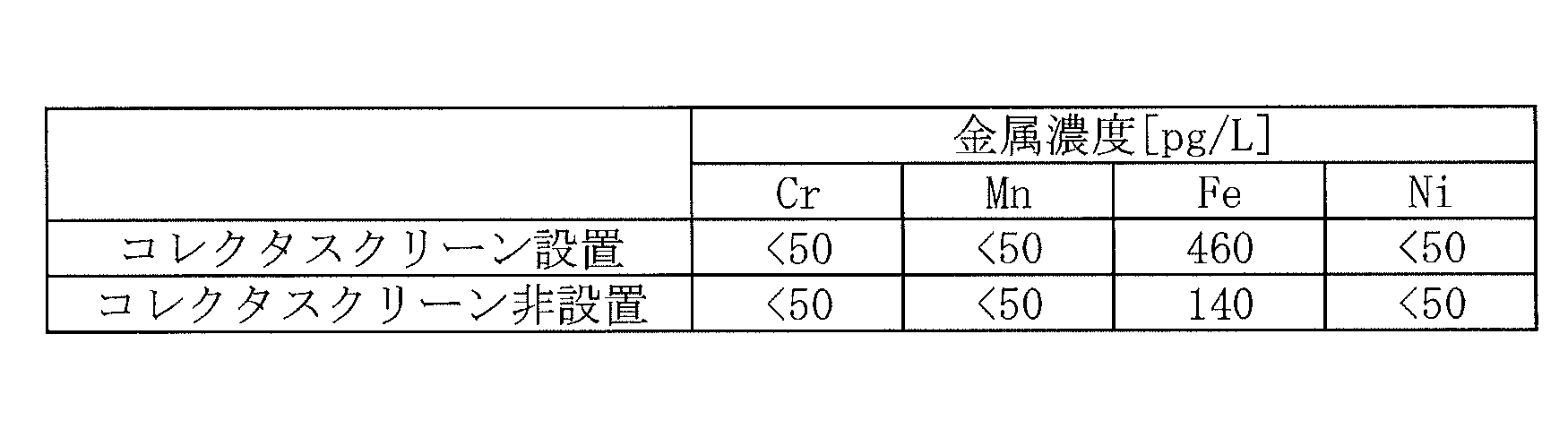
金属(SUS304)製のコレクタスクリーンを設置したことにより、鉄の溶出量が大幅に増加していることが確認された。コレクタスクリーンは、上述したように、ウェッジワイヤースクリーンを円筒状に形成したものであり、その構造上、非金属材料からなるライニングを施すことが困難である。このことも考慮すると、表2に示す測定結果は、コレクタスクリーンの材料としては、非金属材料か、強度の点からは、SUSに含まれる金属元素(具体的には、鉄、ニッケル、クロム、マンガン、アルミニウム、鉛、または銅)を実質的に含まない金属材料が好ましいことを示している。
(試験3)
次に、本発明者らは、コレクタスクリーンを構成する金属材料の違いにより金属成分の溶出量がどのように変化するかを確認するために、樹脂塔に構成材料が異なる2種類のコレクタスクリーンを設置した場合の金属成分の溶出量を比較した。具体的には、接液部にライニングが施されていないことを除いて図1に示す樹脂塔と同様の(したがって、非再生型のイオン交換樹脂を充填した)樹脂塔を用意した。そして、その樹脂塔の流入口と流出口に、SUS(SUS304)製のコレクタスクリーンを設置した場合と、チタン製のコレクタスクリーンを設置した場合のそれぞれにおいて、上述した試験1と同様の手順で試験を行い、容器から流出した試料水中の各種金属濃度を算出した。樹脂塔として、内径が400mm、高さが1000mmのFRP製の塔本体と、PTFE製のソケットとからなるものを用い、試料水として、10L/minの流量で純水を樹脂塔内部に通水した。その他の条件は、上述した試験1と同様である。
次に、本発明者らは、コレクタスクリーンを構成する金属材料の違いにより金属成分の溶出量がどのように変化するかを確認するために、樹脂塔に構成材料が異なる2種類のコレクタスクリーンを設置した場合の金属成分の溶出量を比較した。具体的には、接液部にライニングが施されていないことを除いて図1に示す樹脂塔と同様の(したがって、非再生型のイオン交換樹脂を充填した)樹脂塔を用意した。そして、その樹脂塔の流入口と流出口に、SUS(SUS304)製のコレクタスクリーンを設置した場合と、チタン製のコレクタスクリーンを設置した場合のそれぞれにおいて、上述した試験1と同様の手順で試験を行い、容器から流出した試料水中の各種金属濃度を算出した。樹脂塔として、内径が400mm、高さが1000mmのFRP製の塔本体と、PTFE製のソケットとからなるものを用い、試料水として、10L/minの流量で純水を樹脂塔内部に通水した。その他の条件は、上述した試験1と同様である。
表3に、SUS製のコレクタスクリーンを設置した場合とチタン製のコレクタスクリーンを設置した場合の測定結果を示す。
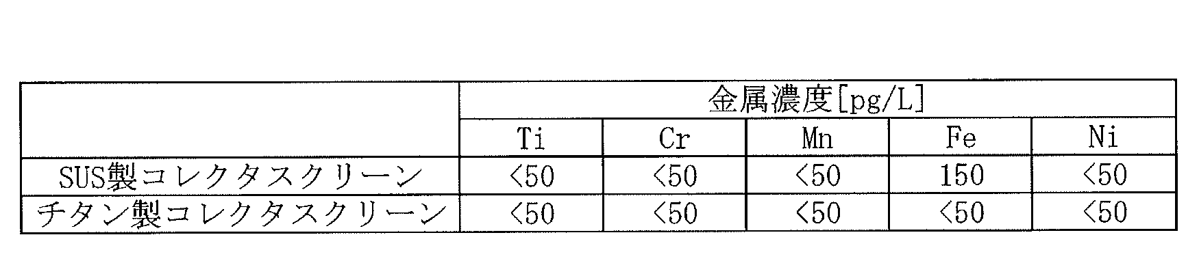
表3に示す測定結果から、SUS製のコレクタスクリーンを設置した場合に比べて、チタン製のコレクタスクリーンを設置した場合に鉄の溶出量が大幅に低減されることが確認され、これにより、コレクタスクリーンの金属材料としてチタンを用いることが好ましいことが確認された。なお、試験2のコレクタスクリーンを設置しない場合に比べても、チタン製のコレクタスクリーンを設置した場合の鉄の溶出量は低減している。このことは、金属成分の溶出の抑制には、フッ素樹脂からなるソケットを用いることも有効であることを示している。
以上のような試験結果を踏まえ、本実施形態では、上述したように、樹脂塔10の接液部のうち少なくとも底面4と出口流路13bの内面に、非金属材料からなるライニングが施されている。加えて、少なくとも下部コレクタスクリーン6の材料として、非金属材料か、あるいは、鉄、ニッケル、クロム、マンガン、アルミニウム、鉛、または銅を実質的に含まない金属材料、好ましくはチタンが用いられている。これにより、イオン交換装置1の接液部の一部、具体的には、そこから金属成分が溶出してもその金属成分がそれより後段においてイオン交換樹脂で処理される可能性がない部分からの金属成分の溶出を抑制することが可能になる。なお、樹脂塔10のライニング材としては、上述したように合成樹脂などの非金属材料が好ましいが、可能な限り金属成分の溶出量が少ないものであれば、金属材料であってもよく、例えば、鉄、ニッケル、クロム、マンガン、アルミニウム、鉛、または銅を実質的に含まない金属材料であってもよい。また、下部コレクタスクリーン6については、必ずしもそれ自体が上述した材料からなる必要はなく、処理水と接する表面(接液部)のみが上述した材料からなっていてもよく、すなわち、非金属材料か、あるいは、鉄、ニッケル、クロム、マンガン、アルミニウム、鉛、または銅を実質的に含まない金属材料からなっていてもよい。
また、図示していないが、樹脂塔10の下部には、出口流路13aに接続する配管が取り付けられている。その配管が、例えばSUSなどの金属製である場合、その内面にもライニングが施されていることが好ましい。その材料としては、樹脂塔10のライニング材と同様に、非金属材料、具体的には、フッ素樹脂などの合成樹脂が好ましく、あるいは、鉄、ニッケル、クロム、マンガン、アルミニウム、鉛、または銅を実質的に含まない金属材料であってもよい。
なお、上述したように、超純水製造装置1の構成は、図示した構成に限定されず、したがって、イオン交換装置1の設置位置も、図示した位置に限定されるものではない。例えば、膜脱気装置25が省略され、それにより、サブシステムの最も下流側のUF膜装置26のすぐ上流側にイオン交換装置1が設置されてもよい。また、膜脱気装置25とUF膜装置26が省略され、それにより、サブシステムの最も下流側にイオン交換装置1が設置されてもよい。また、イオン交換装置1の上述した構成は、本実施形態のようにサブシステムに設置されるイオン交換装置のものに限定されず、一次純水システムを構成するイオン交換装置に適用されてもよい。また、イオン交換装置1に充填されるイオン交換樹脂の充填形態は、上述したカチオン交換樹脂とアニオン交換樹脂との混床形態に限定されず、カチオン交換樹脂とアニオン交換樹脂との複床形態であってもよく、カチオン交換樹脂またはアニオン交換樹脂が単床形態であってもよい。さらに、イオン交換樹脂の代わりに、あるいはそれに加え、キレート樹脂が充填されていてもよい。したがって、例えば、イオン交換装置1は、キレート樹脂が単床で充填されたものであってもよく、カチオン交換樹脂およびアニオン交換樹脂の少なくとも一方とキレート樹脂とが複床または混床で充填されたものであってもよい。
1 イオン交換装置
2 イオン交換樹脂
3 上面
4 底面
5 上部コレクタスクリーン
6 下部コレクタスクリーン
7 側面
8 湾曲面
10樹脂塔(容器)
11 容器本体
12 上部ソケット
12a 入口流路
12b 流入口
13 下部ソケット
13a 出口流路
13b 流出口(開口部)
20 超純水製造装置
21 一次純水タンク
22 ポンプ
23 熱交換器
24 紫外線酸化装置
25 膜脱気装置
26 限外ろ過膜装置
27 ユースポイント
2 イオン交換樹脂
3 上面
4 底面
5 上部コレクタスクリーン
6 下部コレクタスクリーン
7 側面
8 湾曲面
10樹脂塔(容器)
11 容器本体
12 上部ソケット
12a 入口流路
12b 流入口
13 下部ソケット
13a 出口流路
13b 流出口(開口部)
20 超純水製造装置
21 一次純水タンク
22 ポンプ
23 熱交換器
24 紫外線酸化装置
25 膜脱気装置
26 限外ろ過膜装置
27 ユースポイント
Claims (10)
- イオン交換樹脂が充填された容器と、
前記容器内の底面に形成された開口部に連通し、前記イオン交換樹脂で処理された処理水を流通させるための出口流路と、
前記開口部に設けられ、前記容器から前記出口流路への前記イオン交換樹脂の流出を防止するスクリーンと、を有し、
前記出口流路の前記処理水との接液部および前記スクリーンの前記処理水との接液部のそれぞれが、非金属材料、あるいは、鉄、ニッケル、クロム、マンガン、アルミニウム、鉛、または銅を実質的に含まない金属材料からなる、イオン交換装置。 - 前記容器内の前記底面は、前記開口部が形成された水平面を含み、前記水平面が、非金属材料、あるいは、鉄、ニッケル、クロム、マンガン、アルミニウム、鉛、または銅を実質的に含まない金属材料からなる、請求項1に記載のイオン交換装置。
- 前記容器内の前記底面と側面とを接続する湾曲面が、非金属材料、あるいは、鉄、ニッケル、クロム、マンガン、アルミニウム、鉛、または銅を実質的に含まない金属材料からなる、請求項2に記載のイオン交換装置。
- 前記容器が、前記出口流路を規定するソケットを有し、前記ソケットが前記非金属材料からなる、請求項1から3のいずれか1項に記載のイオン交換装置。
- 前記容器の下部に取り付けられて前記出口流路に接続され、前記出口流路からの前記処理水を流通させるための配管を有し、
前記配管の内面が、非金属材料、あるいは、鉄、ニッケル、クロム、マンガン、アルミニウム、鉛、または銅を実質的に含まない金属材料からなる、請求項1から4のいずれか1項に記載のイオン交換装置。 - 前記非金属材料がフッ素樹脂またはポリプロピレンである、請求項1から5のいずれか1項に記載のイオン交換装置。
- 前記鉄、ニッケル、クロム、マンガン、アルミニウム、鉛、または銅を実質的に含まない金属材料がチタンである、請求項1から6のいずれか1項に記載のイオン交換装置。
- 前記スクリーンは、一端が開口する円筒状に形成され、前記一端で前記開口部に取り付けられている、請求項1から7のいずれか1項に記載のイオン交換装置。
- 請求項1から8のいずれか1項に記載のイオン交換装置を有する超純水製造装置。
- イオン交換装置に用いられ、イオン交換樹脂が充填される容器であって、
前記容器内の底面には、前記イオン交換樹脂で処理された処理水を流通させるための出口流路に連通する開口部が形成され、前記開口部には、前記容器から前記出口流路への前記イオン交換樹脂の流出を防止するスクリーンが設けられ、
前記出口流路の前記処理水との接液部および前記スクリーンの前記処理水との接液部のそれぞれが、非金属材料、あるいは、鉄、ニッケル、クロム、マンガン、アルミニウム、鉛、または銅を実質的に含まない金属材料からなる、容器。
Applications Claiming Priority (2)
| Application Number | Priority Date | Filing Date | Title |
|---|---|---|---|
| JP2021-017487 | 2021-02-05 | ||
| JP2021017487A JP7759728B2 (ja) | 2021-02-05 | 2021-02-05 | イオン交換装置および超純水製造装置 |
Publications (1)
| Publication Number | Publication Date |
|---|---|
| WO2022168570A1 true WO2022168570A1 (ja) | 2022-08-11 |
Family
ID=82741314
Family Applications (1)
| Application Number | Title | Priority Date | Filing Date |
|---|---|---|---|
| PCT/JP2022/001262 Ceased WO2022168570A1 (ja) | 2021-02-05 | 2022-01-17 | イオン交換装置および超純水製造装置 |
Country Status (2)
| Country | Link |
|---|---|
| JP (2) | JP7759728B2 (ja) |
| WO (1) | WO2022168570A1 (ja) |
Citations (7)
| Publication number | Priority date | Publication date | Assignee | Title |
|---|---|---|---|---|
| US4028251A (en) * | 1975-10-14 | 1977-06-07 | William Deneen | Agitator for solids-containing vessels |
| JPH05103999A (ja) * | 1991-10-18 | 1993-04-27 | Tosoh Corp | イオン交換樹脂塔 |
| JPH11105847A (ja) * | 1997-09-30 | 1999-04-20 | Toho Titanium Co Ltd | チタン製飲料容器並びにその製造方法 |
| JP2007117781A (ja) * | 2005-10-24 | 2007-05-17 | Japan Organo Co Ltd | イオン交換樹脂、イオン交換樹脂カラム、イオン交換樹脂の含有金属不純物量低減方法、精製装置、及び精製方法 |
| JP2008256364A (ja) * | 2007-03-30 | 2008-10-23 | Kurita Water Ind Ltd | 液体クロマトグラフィ用のフィルタ、その製造方法および液体クロマトグラフィ装置 |
| JP2011067793A (ja) * | 2009-09-28 | 2011-04-07 | Kurita Water Ind Ltd | イオン交換装置 |
| JP2011206722A (ja) * | 2010-03-30 | 2011-10-20 | Kurita Water Ind Ltd | イオン交換装置及び超純水製造装置用サブシステム |
-
2021
- 2021-02-05 JP JP2021017487A patent/JP7759728B2/ja active Active
-
2022
- 2022-01-17 WO PCT/JP2022/001262 patent/WO2022168570A1/ja not_active Ceased
-
2025
- 2025-06-27 JP JP2025109000A patent/JP2025126310A/ja not_active Withdrawn
Patent Citations (7)
| Publication number | Priority date | Publication date | Assignee | Title |
|---|---|---|---|---|
| US4028251A (en) * | 1975-10-14 | 1977-06-07 | William Deneen | Agitator for solids-containing vessels |
| JPH05103999A (ja) * | 1991-10-18 | 1993-04-27 | Tosoh Corp | イオン交換樹脂塔 |
| JPH11105847A (ja) * | 1997-09-30 | 1999-04-20 | Toho Titanium Co Ltd | チタン製飲料容器並びにその製造方法 |
| JP2007117781A (ja) * | 2005-10-24 | 2007-05-17 | Japan Organo Co Ltd | イオン交換樹脂、イオン交換樹脂カラム、イオン交換樹脂の含有金属不純物量低減方法、精製装置、及び精製方法 |
| JP2008256364A (ja) * | 2007-03-30 | 2008-10-23 | Kurita Water Ind Ltd | 液体クロマトグラフィ用のフィルタ、その製造方法および液体クロマトグラフィ装置 |
| JP2011067793A (ja) * | 2009-09-28 | 2011-04-07 | Kurita Water Ind Ltd | イオン交換装置 |
| JP2011206722A (ja) * | 2010-03-30 | 2011-10-20 | Kurita Water Ind Ltd | イオン交換装置及び超純水製造装置用サブシステム |
Also Published As
| Publication number | Publication date |
|---|---|
| TW202239715A (zh) | 2022-10-16 |
| JP7759728B2 (ja) | 2025-10-24 |
| JP2022120535A (ja) | 2022-08-18 |
| JP2025126310A (ja) | 2025-08-28 |
Similar Documents
| Publication | Publication Date | Title |
|---|---|---|
| US5766321A (en) | Apparatus for reducing dissolved oxygen | |
| JP7555184B2 (ja) | 超純水製造装置とその水質管理方法 | |
| WO2023053572A1 (ja) | 超純水製造用イオン交換装置、超純水製造システム、及び超純水製造方法 | |
| WO2004085318A1 (en) | Apparatus and method for continuous electrodeionization | |
| CN103359850A (zh) | 超纯水制造装置 | |
| US5906738A (en) | Apparatus and method for removing impurities from aqueous hydrogen peroxide | |
| US20240158267A1 (en) | Ultrapure water production system | |
| WO2018110177A1 (ja) | イオン交換体充填カートリッジ及び金属除去カラム | |
| WO2022168570A1 (ja) | イオン交換装置および超純水製造装置 | |
| JP3778158B2 (ja) | 超純水製造装置 | |
| DE19610322B4 (de) | Verfahren zur Passivierungsbehandlung eines Rohrleitungssystems für hochreines Gas und seine Verwendung | |
| TWI915495B (zh) | 離子交換裝置及超純水製造裝置 | |
| JP3963319B2 (ja) | 超純水製造装置 | |
| WO2025163967A1 (ja) | 純水製造用ストレーナー及びそれを用いた超純水製造システム、超純水製造方法 | |
| WO2023042723A1 (ja) | イオン交換樹脂の品質評価方法および超純水製造方法 | |
| KR20240087783A (ko) | 전극수의 회수 방법, 및 초순수 또는 제약용수의 제조 방법 | |
| US20250263313A1 (en) | Method for producing ultrapure water, ultrapure water production apparatus, and ultrapure water production system | |
| JP2011206722A (ja) | イオン交換装置及び超純水製造装置用サブシステム | |
| JP2005187306A (ja) | 油田かん水からのヨウ素製造方法 | |
| JP5257175B2 (ja) | 超純水製造装置 | |
| WO2026094554A1 (ja) | 温超純水製造システム | |
| JPH10273193A (ja) | 高純度薬液輸送用大型容器 | |
| JP4968432B2 (ja) | 電気脱イオン装置の流量調整方法 | |
| JP7845087B2 (ja) | イオン交換樹脂カラム | |
| KR0168313B1 (ko) | 용존산소 감소장치 |
Legal Events
| Date | Code | Title | Description |
|---|---|---|---|
| 121 | Ep: the epo has been informed by wipo that ep was designated in this application |
Ref document number: 22749447 Country of ref document: EP Kind code of ref document: A1 |
|
| NENP | Non-entry into the national phase |
Ref country code: DE |
|
| 122 | Ep: pct application non-entry in european phase |
Ref document number: 22749447 Country of ref document: EP Kind code of ref document: A1 |