WO2022163136A1 - ハイブリッド車の制御装置 - Google Patents
ハイブリッド車の制御装置 Download PDFInfo
- Publication number
- WO2022163136A1 WO2022163136A1 PCT/JP2021/044802 JP2021044802W WO2022163136A1 WO 2022163136 A1 WO2022163136 A1 WO 2022163136A1 JP 2021044802 W JP2021044802 W JP 2021044802W WO 2022163136 A1 WO2022163136 A1 WO 2022163136A1
- Authority
- WO
- WIPO (PCT)
- Prior art keywords
- battery
- vehicle
- upper limit
- output value
- output
- Prior art date
- Legal status (The legal status is an assumption and is not a legal conclusion. Google has not performed a legal analysis and makes no representation as to the accuracy of the status listed.)
- Ceased
Links
Images


Classifications
-
- B—PERFORMING OPERATIONS; TRANSPORTING
- B60—VEHICLES IN GENERAL
- B60K—ARRANGEMENT OR MOUNTING OF PROPULSION UNITS OR OF TRANSMISSIONS IN VEHICLES; ARRANGEMENT OR MOUNTING OF PLURAL DIVERSE PRIME-MOVERS IN VEHICLES; AUXILIARY DRIVES FOR VEHICLES; INSTRUMENTATION OR DASHBOARDS FOR VEHICLES; ARRANGEMENTS IN CONNECTION WITH COOLING, AIR INTAKE, GAS EXHAUST OR FUEL SUPPLY OF PROPULSION UNITS IN VEHICLES
- B60K6/00—Arrangement or mounting of plural diverse prime-movers for mutual or common propulsion, e.g. hybrid propulsion systems comprising electric motors and internal combustion engines
- B60K6/20—Arrangement or mounting of plural diverse prime-movers for mutual or common propulsion, e.g. hybrid propulsion systems comprising electric motors and internal combustion engines the prime-movers consisting of electric motors and internal combustion engines, e.g. HEVs
- B60K6/42—Arrangement or mounting of plural diverse prime-movers for mutual or common propulsion, e.g. hybrid propulsion systems comprising electric motors and internal combustion engines the prime-movers consisting of electric motors and internal combustion engines, e.g. HEVs characterised by the architecture of the hybrid electric vehicle
- B60K6/44—Series-parallel type
-
- B—PERFORMING OPERATIONS; TRANSPORTING
- B60—VEHICLES IN GENERAL
- B60L—PROPULSION OF ELECTRICALLY-PROPELLED VEHICLES; SUPPLYING ELECTRIC POWER FOR AUXILIARY EQUIPMENT OF ELECTRICALLY-PROPELLED VEHICLES; ELECTRODYNAMIC BRAKE SYSTEMS FOR VEHICLES IN GENERAL; MAGNETIC SUSPENSION OR LEVITATION FOR VEHICLES; MONITORING OPERATING VARIABLES OF ELECTRICALLY-PROPELLED VEHICLES; ELECTRIC SAFETY DEVICES FOR ELECTRICALLY-PROPELLED VEHICLES
- B60L3/00—Electric devices on electrically-propelled vehicles for safety purposes; Monitoring operating variables, e.g. speed, deceleration or energy consumption
-
- B—PERFORMING OPERATIONS; TRANSPORTING
- B60—VEHICLES IN GENERAL
- B60L—PROPULSION OF ELECTRICALLY-PROPELLED VEHICLES; SUPPLYING ELECTRIC POWER FOR AUXILIARY EQUIPMENT OF ELECTRICALLY-PROPELLED VEHICLES; ELECTRODYNAMIC BRAKE SYSTEMS FOR VEHICLES IN GENERAL; MAGNETIC SUSPENSION OR LEVITATION FOR VEHICLES; MONITORING OPERATING VARIABLES OF ELECTRICALLY-PROPELLED VEHICLES; ELECTRIC SAFETY DEVICES FOR ELECTRICALLY-PROPELLED VEHICLES
- B60L50/00—Electric propulsion with power supplied within the vehicle
- B60L50/50—Electric propulsion with power supplied within the vehicle using propulsion power supplied by batteries or fuel cells
- B60L50/60—Electric propulsion with power supplied within the vehicle using propulsion power supplied by batteries or fuel cells using power supplied by batteries
- B60L50/61—Electric propulsion with power supplied within the vehicle using propulsion power supplied by batteries or fuel cells using power supplied by batteries by batteries charged by engine-driven generators, e.g. series hybrid electric vehicles
-
- B—PERFORMING OPERATIONS; TRANSPORTING
- B60—VEHICLES IN GENERAL
- B60L—PROPULSION OF ELECTRICALLY-PROPELLED VEHICLES; SUPPLYING ELECTRIC POWER FOR AUXILIARY EQUIPMENT OF ELECTRICALLY-PROPELLED VEHICLES; ELECTRODYNAMIC BRAKE SYSTEMS FOR VEHICLES IN GENERAL; MAGNETIC SUSPENSION OR LEVITATION FOR VEHICLES; MONITORING OPERATING VARIABLES OF ELECTRICALLY-PROPELLED VEHICLES; ELECTRIC SAFETY DEVICES FOR ELECTRICALLY-PROPELLED VEHICLES
- B60L58/00—Methods or circuit arrangements for monitoring or controlling batteries or fuel cells, specially adapted for electric vehicles
- B60L58/10—Methods or circuit arrangements for monitoring or controlling batteries or fuel cells, specially adapted for electric vehicles for monitoring or controlling batteries
- B60L58/24—Methods or circuit arrangements for monitoring or controlling batteries or fuel cells, specially adapted for electric vehicles for monitoring or controlling batteries for controlling the temperature of batteries
- B60L58/25—Methods or circuit arrangements for monitoring or controlling batteries or fuel cells, specially adapted for electric vehicles for monitoring or controlling batteries for controlling the temperature of batteries by controlling the electric load
-
- B—PERFORMING OPERATIONS; TRANSPORTING
- B60—VEHICLES IN GENERAL
- B60W—CONJOINT CONTROL OF VEHICLE SUB-UNITS OF DIFFERENT TYPE OR DIFFERENT FUNCTION; CONTROL SYSTEMS SPECIALLY ADAPTED FOR HYBRID VEHICLES; ROAD VEHICLE DRIVE CONTROL SYSTEMS FOR PURPOSES NOT RELATED TO THE CONTROL OF A PARTICULAR SUB-UNIT
- B60W10/00—Conjoint control of vehicle sub-units of different type or different function
- B60W10/24—Conjoint control of vehicle sub-units of different type or different function including control of energy storage means
- B60W10/26—Conjoint control of vehicle sub-units of different type or different function including control of energy storage means for electrical energy, e.g. batteries or capacitors
-
- B—PERFORMING OPERATIONS; TRANSPORTING
- B60—VEHICLES IN GENERAL
- B60W—CONJOINT CONTROL OF VEHICLE SUB-UNITS OF DIFFERENT TYPE OR DIFFERENT FUNCTION; CONTROL SYSTEMS SPECIALLY ADAPTED FOR HYBRID VEHICLES; ROAD VEHICLE DRIVE CONTROL SYSTEMS FOR PURPOSES NOT RELATED TO THE CONTROL OF A PARTICULAR SUB-UNIT
- B60W20/00—Control systems specially adapted for hybrid vehicles
-
- B—PERFORMING OPERATIONS; TRANSPORTING
- B60—VEHICLES IN GENERAL
- B60W—CONJOINT CONTROL OF VEHICLE SUB-UNITS OF DIFFERENT TYPE OR DIFFERENT FUNCTION; CONTROL SYSTEMS SPECIALLY ADAPTED FOR HYBRID VEHICLES; ROAD VEHICLE DRIVE CONTROL SYSTEMS FOR PURPOSES NOT RELATED TO THE CONTROL OF A PARTICULAR SUB-UNIT
- B60W20/00—Control systems specially adapted for hybrid vehicles
- B60W20/10—Controlling the power contribution of each of the prime movers to meet required power demand
- B60W20/13—Controlling the power contribution of each of the prime movers to meet required power demand in order to stay within battery power input or output limits; in order to prevent overcharging or battery depletion
-
- Y—GENERAL TAGGING OF NEW TECHNOLOGICAL DEVELOPMENTS; GENERAL TAGGING OF CROSS-SECTIONAL TECHNOLOGIES SPANNING OVER SEVERAL SECTIONS OF THE IPC; TECHNICAL SUBJECTS COVERED BY FORMER USPC CROSS-REFERENCE ART COLLECTIONS [XRACs] AND DIGESTS
- Y02—TECHNOLOGIES OR APPLICATIONS FOR MITIGATION OR ADAPTATION AGAINST CLIMATE CHANGE
- Y02T—CLIMATE CHANGE MITIGATION TECHNOLOGIES RELATED TO TRANSPORTATION
- Y02T10/00—Road transport of goods or passengers
- Y02T10/60—Other road transportation technologies with climate change mitigation effect
- Y02T10/62—Hybrid vehicles
Definitions
- the present invention relates to an output control device for an onboard battery in a hybrid vehicle.
- hybrid vehicles that have been developed in recent years are able to supply the electric power output from the generator driven by the engine to the drive motor to drive the vehicle, as well as supply it to the on-board battery for charging.
- a hybrid vehicle having an engine, a generator, and an on-board battery as described above, when a drive motor requires high output, both the electric power output from the generator driven by the engine and the electric power output from the on-board battery are used. is used to develop a vehicle capable of driving a drive motor.
- Patent Document 1 describes a control device for a hybrid vehicle that suppresses the output from the onboard battery based on the temperature of the onboard battery in order to suppress the temperature rise of the onboard battery.
- the present invention has been made in view of such problems, and its object is to provide a control device for a hybrid vehicle that can improve acceleration performance while suppressing an increase in battery temperature in a series mode. It is in.
- the hybrid vehicle control device of the present invention is driven by an onboard battery, an engine, a generator driven by the engine to generate power, and electric power supplied from the onboard battery or the generator.
- a motor for driving running wheels of the vehicle and capable of a series mode in which the engine is driven to generate power by the generator while the motor is used to drive the hybrid vehicle, wherein the series mode is mode, a battery upper limit output value setting unit for setting a battery upper limit output value as a reference value, a vehicle speed detection unit for detecting the vehicle speed, and a request for vehicle running.
- the battery upper limit output value setting unit sets the battery upper limit output value higher than the reference value when the required output is a predetermined value or more and a high output is requested in the series mode. It is characterized in that output suppression mitigation control is performed to set the battery output higher for a predetermined period of time, and the battery upper limit output value and the predetermined period of time are changed based on the vehicle speed.
- the battery upper limit output value is set high for a predetermined period of time by output suppression relaxation control, thereby increasing the power supplied from the on-board battery and supplying it to the motor, thereby increasing driving force. Increase to improve the acceleration performance of the vehicle.
- the battery upper limit output value and the predetermined time based on the vehicle speed, it is possible to output electric power from the on-vehicle battery that is suitable for each acceleration request during low speed running and high speed running.
- the battery upper limit output value setting unit lowers the battery upper limit output value when the vehicle speed is higher than or equal to a predetermined speed than when the vehicle speed is lower than the predetermined speed, and It is preferable to set the predetermined time longer than the reference value while setting it higher.
- the battery upper limit output value is kept lower than when accelerating at low vehicle speeds to suppress the temperature rise of the on-board battery, and the battery upper limit output value is kept lower than the long-term reference value.
- the battery upper limit output value setting unit reduces the battery upper limit output value in stages from a value higher than the reference value to the reference value after the predetermined time has elapsed.
- the battery's upper limit output value is finely changed to suppress the temperature rise of the on-board battery and further improve acceleration performance.
- a battery temperature detection unit that detects the temperature of the on-vehicle battery
- the battery upper limit output value setting unit detects, in the output suppression mitigation control, based on the temperature of the on-vehicle battery, the lower the temperature, the lower the temperature. It is preferable to increase the number of steps for lowering the battery upper limit output value to the reference value. As a result, the lower the temperature of the vehicle battery, the finer the battery upper limit output value can be changed, and the acceleration performance can be improved more appropriately while suppressing the temperature rise of the vehicle battery.
- the battery upper limit output value setting unit selects the battery upper limit based on the selected operating mode in the output suppression mitigation control. Change the output value.
- the battery upper limit output value setting unit selects the battery upper limit based on the selected operating mode in the output suppression mitigation control. Change the output value.
- the battery upper limit output value and the predetermined period of time are adjusted according to the vehicle speed. Since it is changed, the output from the vehicle-mounted battery can be appropriately suppressed according to the vehicle speed. For example, when the vehicle speed is high, the battery upper limit output value is reduced more than when the vehicle speed is low, and by increasing the duration of increasing the battery upper limit output value from the reference value for a predetermined period of time, a relatively suppressed output is maintained for a long time. of power can be increased. On the other hand, when the vehicle speed is low, high output is possible for a short period of time and acceleration performance can be improved.
- FIG. 1 is a schematic configuration diagram of a traveling drive system of a vehicle according to one embodiment of the present invention
- FIG. 1 is a configuration diagram of a battery output control system of this embodiment
- FIG. 7 is a graph showing a setting example of a battery upper limit output value when the on-vehicle battery is in a low temperature state
- 7 is a graph showing a setting example of a battery upper limit output value when the on-vehicle battery is in a high temperature state.
- 7 is a graph showing a setting example of battery upper limit output value based on vehicle speed and driver selection mode
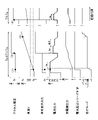
- 5 is a time chart showing transition examples of accelerator opening, vehicle speed, battery output, generator output, battery high temperature series determination, and driving mode determination during acceleration.
- FIG. 1 is a schematic configuration diagram of a plug-in hybrid vehicle (hereinafter referred to as vehicle 1) according to one embodiment of the present invention.
- vehicle 1 equipped with the battery output control system (control device) of this embodiment can run by driving the front wheels 3 (running wheels) by the output of the engine 2, and the front wheels 3 can be driven by the output of the engine 2.
- vehicle 1 equipped with the battery output control system (control device) of this embodiment can run by driving the front wheels 3 (running wheels) by the output of the engine 2, and the front wheels 3 can be driven by the output of the engine 2.
- It is a four-wheel drive vehicle equipped with an electric front motor 4 for driving and an electric rear motor 6 for driving rear wheels 5 (running wheels).
- the engine 2 can drive the drive shaft 8 of the front wheels 3 via the speed reducer 7 and drive the motor generator 9 (generator) via the speed reducer 7 to generate power.
- the front motor 4 is driven by being supplied with high-voltage electric power from an onboard battery 11 mounted on the vehicle 1 and a motor generator 9 via a front inverter 10, and drives a drive shaft 8 of the front wheels 3 via a speed reducer 7. drive.
- the speed reducer 7 incorporates a clutch 7a capable of switching power transmission between the output shaft of the engine 2 and the drive shaft 8 of the front wheel 3.
- the rear motor 6 is driven by being supplied with high-voltage power from the vehicle-mounted battery 11 and the motor generator 9 via the rear inverter 12 , and drives the drive shaft 14 of the rear wheel 5 via the speed reducer 13 .
- the electric power generated by the motor generator 9 can charge the onboard battery 11 via the front inverter 10 and can also supply electric power to the front motor 4 and the rear motor 6 .
- the in-vehicle battery 11 is composed of a secondary battery such as a lithium ion battery, and has a battery module (not shown) configured by collectively configuring a plurality of battery cells.
- the vehicle-mounted battery 11 also includes a monitoring unit 11a (battery temperature detector) that monitors the state of the battery module, such as the voltage and temperature of the battery module.
- the front inverter 10 has a function of controlling the output of the front motor 4 based on the control signal from the hybrid ECU 20 and controlling the output of the motor generator 9 based on the control signal from the hybrid ECU 20 .
- Rear inverter 12 has a function of controlling the output of rear motor 6 based on a control signal from hybrid ECU 20 .
- the vehicle 1 is provided with an engine ECU 22 that drives and controls the engine 2 and a charger (not shown) that charges the vehicle battery 11 with an external power source.
- the hybrid ECU 20 is a comprehensive control device for performing travel control of the vehicle 1, and includes an input/output device, a storage device (ROM, RAM, nonvolatile RAM, etc.), a central processing unit (CPU), a timer, and the like. It is configured.
- the engine ECU 22 also includes an input/output device, a storage device (ROM, RAM, non-volatile RAM, etc.), a central processing unit (CPU), a timer, and the like.
- a monitoring unit 11a for the onboard battery 11 for the onboard battery 11, a front inverter 10, a rear inverter 12, an engine control unit 22, an accelerator opening sensor 40 for detecting the amount of accelerator operation, and a running speed of the vehicle 1 (vehicle speed V), a vehicle speed sensor 41 (vehicle speed detector) and a mode selection switch 42 (driving mode selector) for selecting the driving mode (NOMAL mode, POWER mode, etc.) of the vehicle 1 are connected. detection, actuation and operation information is input.
- a front inverter 10, a rear inverter 12, a reduction gear 7 (clutch 7a), and an engine control unit 22 are connected to the output side of the hybrid control unit 20.
- the hybrid control unit 20 detects the above-mentioned various detection amounts and various operation information of the accelerator opening sensor 40, the vehicle speed sensor 41, the mode selection switch 42, etc., and controls the vehicle required output and driving force required for driving the vehicle 1. calculate the torque, send a control signal to the engine control unit 22, the front inverter 10, the rear inverter 12, and the reduction gear 7, and switch the running mode ((EV mode: electric vehicle mode), series mode, parallel mode), The output of the engine 2, the front motor 4, the rear motor 6, and the output of the motor generator 9 are controlled.
- EV mode electric vehicle mode
- series mode series mode
- parallel mode The output of the engine 2, the front motor 4, the rear motor 6, and the output of the motor generator 9 are controlled.
- the engine 2 In the EV mode, the engine 2 is stopped, and the front motor 4 and the rear motor 6 are driven by electric power supplied from the onboard battery 11 to run the vehicle 1 .
- the clutch 7a of the speed reducer 7 In the series mode, the clutch 7a of the speed reducer 7 is disengaged and the motor generator 9 is operated by the engine 2. The electric power generated by the motor generator 9 and the electric power supplied from the vehicle battery 11 are used to drive the front motor 4 and the rear motor 6 to run the vehicle.
- the rotation speed of the engine 2 In the series mode, the rotation speed of the engine 2 is set to a predetermined rotation speed, and surplus electric power is supplied to the vehicle battery 11 to charge the vehicle battery 11 .
- the clutch 7a of the speed reducer 7 is connected, and power is mechanically transmitted from the engine 2 through the speed reducer 7 to drive the front wheels 3.
- the front motor 4 and the rear motor 6 are driven by electric power generated by operating the motor generator 9 by the engine 2 and electric power supplied from the onboard battery 11 to drive the vehicle.
- the hybrid control unit 20 sets the running mode to the parallel mode in areas where the engine 2 is efficient, such as high-speed areas. Further, in a region other than the parallel mode, that is, in the middle/low speed region, switching is made between the EV mode and the series mode based on the driving torque of the vehicle 1 and the state of charge SOC of the vehicle battery 11 .
- the vehicle 1 is equipped with a charge/discharge control unit 50 that controls the input/output of the onboard battery 11 .
- the charge/discharge control unit 50 has a function of controlling power input/output from the vehicle battery 11 based on a control signal from the hybrid ECU 20 .
- the charge/discharge control unit 50 regulates the output from the vehicle battery 11 so that the output from the vehicle battery 11 does not exceed the upper limit value (hereinafter referred to as the battery upper limit output value) input from the hybrid ECU 20 .
- FIG. 2 is a block diagram showing the configuration of the battery output control system 51 of this embodiment.
- the battery output control system 51 of the present embodiment includes a charge/discharge control unit 50, a vehicle required output calculation unit 52 and a driving mode determination unit 53 provided in the hybrid ECU 20, and a battery upper limit output value setting unit 54. ing.
- the vehicle required output calculation unit 52 calculates the vehicle required output based on the accelerator opening, the vehicle speed V, and the like, as described above.
- the running mode determination unit 53 determines the running mode of the vehicle based on the accelerator opening, the vehicle speed V, and the like, as described above.
- the battery upper limit output value setting unit 54 inputs the driving mode (EV mode, series mode, parallel mode) determined by the driving mode determination unit 53 of the hybrid ECU 20 based on the accelerator operation amount, the vehicle speed V, etc. as described above.
- the vehicle speed V from the vehicle speed sensor 41, the temperature of the vehicle battery 11 (battery temperature T) from the monitoring unit 11a, and the driver selection mode (driving mode) from the mode selection switch 42 are input.
- the driver selection mode is selected by the driver operating a mode selection switch 42 installed near the driver's seat of the vehicle 1 .
- the driver selection modes are driving modes in which the acceleration performance of the vehicle 1 differs, and for example, NORMAL mode and POWER mode can be selected.
- the POWER mode is selected when acceleration performance is more important than fuel efficiency performance.
- the battery upper limit output value setting unit 54 sets the battery upper limit output when the required vehicle output calculated by the required vehicle output calculation unit 52 is less than the suppression mitigation threshold value Pr (predetermined value) and a low output is requested (normal time).
- Pr suppression mitigation threshold value
- a value Pmax is set to the reference value P1.
- the battery upper limit output value Pmax is set to a value higher than the reference value P1
- the reference value Pmax is set to a value higher than the reference value P1.
- Output suppression mitigation control is performed to restore the value P1.
- This output suppression relaxation control permits the output value from the on-vehicle battery 11 to temporarily increase to a value higher than the reference value P1 when a high output is requested, so that power supply to the motors 4 and 6 of the vehicle 1 is allowed. can be increased, and the acceleration performance of the vehicle 1 can be improved. Then, after a predetermined time (ta or ta+tb) has elapsed, the battery upper limit output value Pmax is returned to the reference value P1, thereby avoiding a continued increase in the output from the vehicle battery 11 and increasing the temperature of the vehicle battery 11. is suppressed.
- the motor generator 9 since the output suppression mitigation control is enabled in the series mode, even if the battery upper limit output value Pmax changes and the output value from the onboard battery 11 is restricted, the motor generator 9 also supplies power to the motors 4 and 6. is supplied to cover the power required for running. Therefore, even if the battery upper limit output value Pmax is changed, the variation in the running output of the vehicle 1 is suppressed. Furthermore, in the present embodiment, the battery upper limit output value setting unit 54 changes the battery upper limit output value Pmax based on the vehicle speed V, battery temperature T, and driver selection mode at the start of output suppression mitigation control in the series mode.
- FIG. 3 and 4 are graphs showing setting examples of the battery upper limit output value Pmax, and are graphs showing changes in the set value of the battery upper limit output value Pmax in output suppression mitigation control.
- FIG. 3 shows the battery upper limit output value Pmax in a low temperature state in which the battery temperature T is less than the predetermined temperature Ta.
- FIG. 4 shows the battery upper limit output value Pmax when the battery temperature T is at a high temperature equal to or higher than the predetermined temperature Ta.
- the battery upper limit output is reached.
- the value Pmax increases, when the battery temperature T at this time is in a low temperature state below a predetermined temperature Ta (T ⁇ Ta) and the vehicle speed V is a low vehicle speed below a predetermined vehicle speed V2 (V ⁇ V2), the battery
- the upper limit output value Pmax is set to a value (for example, P5) higher than the reference value P1.
- the battery upper limit output value Pmax is maintained at this high value for a predetermined time ta (for example, several seconds), and then returned to the reference value P1.
- ta for example, several seconds
- the set value of the battery upper limit output value Pmax may be changed according to the vehicle speed V within a range higher than the reference value P1.
- the battery temperature T is in a low temperature state below a predetermined temperature Ta (T ⁇ Ta) and the vehicle speed V is a high vehicle speed equal to or higher than a predetermined vehicle speed V2 (V ⁇ V2)
- the upper limit output value Pmax is set to a value higher than the reference value P1 and lower than the set value P5 for low vehicle speed (for example, the battery upper limit output value P4) and maintained for a predetermined time ta.
- the set value is lowered to a set value P2 higher than the reference value P1, maintained for a predetermined time tb, and then lowered to the reference value P1.
- Both of the predetermined times ta and tb are about several seconds, but the predetermined time tb is equal to or longer than the predetermined time ta (tb ⁇ ta). It can be set as appropriate.
- the predetermined time tb may be changed according to the vehicle speed V as shown in FIG. 5 which will be described later.
- the battery upper limit output value that is set immediately after the high output request is started.
- Pmax is set to a set value P3 that is lower than the battery upper limit output values P4 and P5 in the low temperature state, and is maintained for a predetermined time ta.
- the battery upper limit output value Pmax is set to the reference value P1, as in the low temperature and low speed state described above.
- the battery upper limit output is set for a predetermined time ta immediately after the start of the high output request (Aos in FIGS. 3 and 4).
- the value Pmax is changed according to the vehicle speed V, and the battery upper limit output value P4 at high vehicle speeds is kept lower than the battery upper limit output value P5 at low vehicle speeds (P4 ⁇ P5).
- the battery upper limit output value Pmax at low vehicle speeds is switched back to the reference value P1, but at high vehicle speeds the battery upper limit output value Pmax is set to P2, which is higher than the reference value P1.
- battery upper limit output value Pmax is set to a value higher than reference value P1 for a longer period of time than at low vehicle speeds.
- FIG. 5 is a graph showing a setting example of the battery upper limit output value Pmax according to the vehicle speed V and the driver selection mode.
- the vehicle speed V is classified into four stages of low speed (V ⁇ V1), medium low speed (V1 ⁇ V ⁇ V2), medium high speed (V2 ⁇ V ⁇ V3), and high speed (V3 ⁇ V).
- the battery upper limit output value Pmax which is set for a predetermined time ta immediately after the start of the high output request (Aos) is set to different values in four stages according to the vehicle speed range. .
- the battery upper limit output value Pmax immediately after the start of the high output request is set to a higher value in a region where the vehicle speed V is low than in a region where the vehicle speed V is high.
- the battery upper limit output value Pmax which is set immediately after the start of the high output request, is set higher than in the NORMAL mode.
- the battery upper limit output value Pmax which is set when the vehicle speed V is equal to or higher than the predetermined vehicle speed V2 after the predetermined time ta has elapsed, when the vehicle speed V is at a high vehicle speed (V ⁇ V3) than when the vehicle speed is medium to high (V ⁇ V3). is set longer (predetermined time tb1 at medium and high vehicle speeds ⁇ predetermined time tb2 at high vehicle speeds).
- the battery upper limit output value Pmax which is set after a predetermined time ta has elapsed from the start of the high output request, is set to the same set value P2 when the vehicle speed V is medium to high or high.
- FIG. 6 shows the accelerator opening, vehicle speed V, battery output (battery upper limit output value Pmax, actual output P), generator output, battery high temperature series determination, and driving mode determination during acceleration in the vehicle 1 of this embodiment. It is a time chart which shows a transition example.
- the diagram on the left side of FIG. 6 shows an example of transition in a low temperature state (Tb ⁇ T ⁇ Ta) in which the battery temperature T is in the range between the predetermined temperatures Ta and Tb
- the diagram on the right side of FIG. shows an example of transition in a high temperature state (T ⁇ Ta) in which is equal to or higher than a predetermined temperature Ta.
- the predetermined temperature Tb is a value lower than the predetermined temperature Ta (Tb ⁇ Ta), and in a low temperature state (T ⁇ Tb) where the battery temperature T is less than the predetermined temperature Tb, the performance of the vehicle battery 11 may not be ensured. , output suppression mitigation control is not executed.
- the series determination condition is, for example, that the vehicle speed V is equal to or greater than the engine start threshold value Vs (V ⁇ Vs).
- V ⁇ Vs the engine start threshold value
- the engine 2 is started and the series mode is entered ( ⁇ 1> in FIG. 6).
- the power suppression mitigation control is performed to increase the battery upper limit output value Pmax again ( ⁇ 2 in FIG. 6). >).
- the battery upper limit output value Pmax is set to P2, which is higher than the reference value P1, for a predetermined time tb2. Stepwise output suppression mitigation control is performed.
- the traveling mode transitions from the series mode to the parallel mode ( ⁇ 3> in FIG. 6).
- the battery upper limit output value Pmax changes, and the actual battery output is also limited accordingly, but in the series mode, the output from the generator is added to satisfy the vehicle required output.
- the battery temperature T is in a high temperature state (T ⁇ Ta) equal to or higher than the predetermined temperature Ta, and the required vehicle output is equal to or higher than the suppression relaxation threshold value Pr, and the output suppression is relaxed.
- the battery upper limit output value Pmax is set to be lower than in the low temperature state, and, similarly to the low speed state, the battery upper limit output value Pmax is set to the reference value P1 after the elapse of the predetermined time ta. Lower.
- the battery upper limit output value Pmax is set to the reference value P1 by the output suppression mitigation control executed in the series mode. 11 output is suppressed to suppress temperature rise of the vehicle battery 11, and the output value from the vehicle battery 11 is permitted to temporarily increase to a value higher than the reference value P1 when a high output is requested. can improve the acceleration performance of
- the battery upper limit output value Pmax immediately after the high output request is changed based on the vehicle speed V. of power output.
- the vehicle speed V at the start of the output relaxation control is divided into four stages, and as the vehicle speed V decreases, the battery upper limit output value Pmax immediately after the start of the output suppression relaxation control increases. It is possible to accelerate.
- the battery upper limit output value Pmax immediately after the start of output suppression mitigation control is suppressed more than at low vehicle speeds. can. Therefore, acceleration at high vehicle speeds can be made possible for a long time.
- the battery upper limit output value Pmax is set relatively high to improve acceleration performance while avoiding an increase in battery temperature and a decrease in battery capacity.
- the battery upper limit output value Pmax is set to a value higher than the reference value P1 and lower than when the vehicle speed is low. is set for a long time, it is possible to accelerate for a long time while avoiding an excessive increase in the battery temperature T and a decrease in the battery capacity.
- the battery upper limit output value can be finely changed step by step to suppress the temperature rise of the on-vehicle battery 11 while controlling the vehicle speed V. Acceleration is possible and drivability can be improved.
- the battery upper limit output value Pmax is set to the reference value P1
- the value is lowered to the reference value P1 in two stages.
- the lower the battery temperature T the more the number of steps for gradually lowering the battery upper limit output value Pmax to the reference value P1. can be improved.
- the battery upper limit output value Pmax is set to different values based on the driver selection mode (for example, NORMAL mode and POWER mode) selected by the mode selection switch 42 .
- the driver selection mode for example, NORMAL mode and POWER mode
- the battery upper limit output value Pmax can be set higher than in the NORMAL mode to obtain a driving output suitable for the driver selection mode.
- the predetermined time ta for increasing the battery upper limit output value Pmax in the initial output suppression mitigation control is set to a constant value regardless of the battery temperature T and the vehicle speed V. It may be changed according to V. For example, the predetermined time ta may be increased as the battery temperature T decreases, or the predetermined time ta may be increased as the vehicle speed V decreases.
- the set value P2 of the battery upper limit output value P which is set after the elapse of the predetermined time ta at medium to high speed or high vehicle speed, may be changed according to the battery temperature T and the vehicle speed V.
- the set value P2 may be increased as the battery temperature T decreases, or the set value P2 may be increased as the vehicle speed V decreases.
- the vehicle 1 of the above embodiment is a four-wheel drive plug-in hybrid vehicle
- the present invention may be applied to a two-wheel drive vehicle or a non-plug-in hybrid vehicle.
- INDUSTRIAL APPLICABILITY The present invention can be widely applied to hybrid vehicles capable of the series mode.
- vehicle 2 engine 4 front motor (motor) 6 rear motor (motor) 9 Motor generator (generator) 11 vehicle battery 11a monitoring unit (battery temperature detector) 20 hybrid control unit 41 vehicle speed sensor (vehicle speed detector) 42 Mode selection switch (operation mode selection part) 50 charge/discharge control unit 51 battery output control system (control device) 52 Vehicle required output calculation unit 53 Driving mode determination unit 54 Battery upper limit output value setting unit
Landscapes
- Engineering & Computer Science (AREA)
- Transportation (AREA)
- Mechanical Engineering (AREA)
- Sustainable Energy (AREA)
- Power Engineering (AREA)
- Life Sciences & Earth Sciences (AREA)
- Sustainable Development (AREA)
- Chemical & Material Sciences (AREA)
- Combustion & Propulsion (AREA)
- Automation & Control Theory (AREA)
- Hybrid Electric Vehicles (AREA)
- Electric Propulsion And Braking For Vehicles (AREA)
- Secondary Cells (AREA)
Priority Applications (1)
| Application Number | Priority Date | Filing Date | Title |
|---|---|---|---|
| JP2022538882A JP7235173B2 (ja) | 2021-01-26 | 2021-12-06 | ハイブリッド車の制御装置 |
Applications Claiming Priority (2)
| Application Number | Priority Date | Filing Date | Title |
|---|---|---|---|
| JP2021-010299 | 2021-01-26 | ||
| JP2021010299 | 2021-01-26 |
Publications (1)
| Publication Number | Publication Date |
|---|---|
| WO2022163136A1 true WO2022163136A1 (ja) | 2022-08-04 |
Family
ID=82653299
Family Applications (1)
| Application Number | Title | Priority Date | Filing Date |
|---|---|---|---|
| PCT/JP2021/044802 Ceased WO2022163136A1 (ja) | 2021-01-26 | 2021-12-06 | ハイブリッド車の制御装置 |
Country Status (2)
| Country | Link |
|---|---|
| JP (1) | JP7235173B2 (https=) |
| WO (1) | WO2022163136A1 (https=) |
Cited By (1)
| Publication number | Priority date | Publication date | Assignee | Title |
|---|---|---|---|---|
| JP7666747B1 (ja) * | 2024-03-01 | 2025-04-22 | 三菱自動車工業株式会社 | ハイブリッド車両の制御方法および装置 |
Families Citing this family (1)
| Publication number | Priority date | Publication date | Assignee | Title |
|---|---|---|---|---|
| JP2025014737A (ja) * | 2023-07-19 | 2025-01-30 | トヨタ自動車株式会社 | 電動車両制御装置、電動車両およびその制御方法 |
Citations (4)
| Publication number | Priority date | Publication date | Assignee | Title |
|---|---|---|---|---|
| JP2012057553A (ja) * | 2010-09-09 | 2012-03-22 | Mitsubishi Motors Corp | 車両の制御装置 |
| JP2015150974A (ja) * | 2014-02-13 | 2015-08-24 | トヨタ自動車株式会社 | ハイブリッド車両の制御装置 |
| JP2016046919A (ja) * | 2014-08-22 | 2016-04-04 | トヨタ自動車株式会社 | 自動車 |
| JP2019094013A (ja) * | 2017-11-27 | 2019-06-20 | トヨタ自動車株式会社 | ハイブリッド自動車 |
-
2021
- 2021-12-06 WO PCT/JP2021/044802 patent/WO2022163136A1/ja not_active Ceased
- 2021-12-06 JP JP2022538882A patent/JP7235173B2/ja active Active
Patent Citations (4)
| Publication number | Priority date | Publication date | Assignee | Title |
|---|---|---|---|---|
| JP2012057553A (ja) * | 2010-09-09 | 2012-03-22 | Mitsubishi Motors Corp | 車両の制御装置 |
| JP2015150974A (ja) * | 2014-02-13 | 2015-08-24 | トヨタ自動車株式会社 | ハイブリッド車両の制御装置 |
| JP2016046919A (ja) * | 2014-08-22 | 2016-04-04 | トヨタ自動車株式会社 | 自動車 |
| JP2019094013A (ja) * | 2017-11-27 | 2019-06-20 | トヨタ自動車株式会社 | ハイブリッド自動車 |
Cited By (2)
| Publication number | Priority date | Publication date | Assignee | Title |
|---|---|---|---|---|
| JP7666747B1 (ja) * | 2024-03-01 | 2025-04-22 | 三菱自動車工業株式会社 | ハイブリッド車両の制御方法および装置 |
| WO2025182065A1 (ja) * | 2024-03-01 | 2025-09-04 | 三菱自動車工業株式会社 | ハイブリッド車両の制御方法および装置 |
Also Published As
| Publication number | Publication date |
|---|---|
| JP7235173B2 (ja) | 2023-03-08 |
| JPWO2022163136A1 (https=) | 2022-08-04 |
Similar Documents
| Publication | Publication Date | Title |
|---|---|---|
| CN103879400B (zh) | 混合动力车辆的行驶模式切换控制器 | |
| EP1433641B1 (en) | Drive control apparatus for hybrid vehicle | |
| EP3296134B1 (en) | Operation control system for hybrid vehicle | |
| KR101339264B1 (ko) | 하이브리드 차량의 충방전 제어 방법 및 시스템 | |
| EP3138713B1 (en) | Hybrid vehicle | |
| EP3238971B1 (en) | Travel driving apparatus of vehicle | |
| KR101889648B1 (ko) | 하이브리드 차량의 제어 장치, 하이브리드 차량 및 하이브리드 차량의 제어 방법 | |
| CN107264294B (zh) | 车辆的行进驱动装置 | |
| JP2005218250A (ja) | トルク制御装置 | |
| JP7235173B2 (ja) | ハイブリッド車の制御装置 | |
| JP7794598B2 (ja) | 四輪駆動電動化車両の駆動制御装置 | |
| KR101518898B1 (ko) | 플러그인 하이브리드 자동차의 충전지향모드 제어장치 및 방법 | |
| JP7372597B2 (ja) | 車両の走行制御装置 | |
| JP2017103980A (ja) | 車両の回生制御装置 | |
| KR20210127269A (ko) | 사륜 구동 전동화 차량의 구동 제어 장치 및 방법 | |
| KR20190048254A (ko) | 하이브리드 전기 자동차의 강제 사륜구동장치 및 그 방법 | |
| JP2012188062A (ja) | ハイブリッド車の空調制御装置 | |
| JP2008001301A (ja) | ハイブリッド車両の制御装置 | |
| WO2023157227A1 (ja) | ハイブリッド車の駆動制御装置 | |
| JP7216329B2 (ja) | 車両の制御装置 | |
| WO2026083487A1 (ja) | ハイブリッド車の駆動制御装置 | |
| JP2014043183A (ja) | ハイブリッド車両 | |
| JP7632739B2 (ja) | ハイブリッド車両 | |
| JP2011225077A (ja) | ハイブリッド自動車 | |
| JP2010252427A (ja) | 自動車およびこれに搭載された二次電池の充電方法 |
Legal Events
| Date | Code | Title | Description |
|---|---|---|---|
| ENP | Entry into the national phase |
Ref document number: 2022538882 Country of ref document: JP Kind code of ref document: A |
|
| 121 | Ep: the epo has been informed by wipo that ep was designated in this application |
Ref document number: 21923141 Country of ref document: EP Kind code of ref document: A1 |
|
| NENP | Non-entry into the national phase |
Ref country code: DE |
|
| 122 | Ep: pct application non-entry in european phase |
Ref document number: 21923141 Country of ref document: EP Kind code of ref document: A1 |