WO2022162889A1 - Cathéter - Google Patents
Cathéter Download PDFInfo
- Publication number
- WO2022162889A1 WO2022162889A1 PCT/JP2021/003329 JP2021003329W WO2022162889A1 WO 2022162889 A1 WO2022162889 A1 WO 2022162889A1 JP 2021003329 W JP2021003329 W JP 2021003329W WO 2022162889 A1 WO2022162889 A1 WO 2022162889A1
- Authority
- WO
- WIPO (PCT)
- Prior art keywords
- shape
- handle body
- catheter
- tip
- handle
- Prior art date
Links
- 230000007246 mechanism Effects 0.000 claims abstract description 57
- 239000007788 liquid Substances 0.000 claims description 40
- 230000002262 irrigation Effects 0.000 claims description 20
- 238000003973 irrigation Methods 0.000 claims description 20
- 230000001681 protective effect Effects 0.000 claims description 14
- 230000008859 change Effects 0.000 claims description 2
- 230000000052 comparative effect Effects 0.000 description 12
- 238000002679 ablation Methods 0.000 description 6
- 239000000463 material Substances 0.000 description 5
- 230000000694 effects Effects 0.000 description 4
- 238000005259 measurement Methods 0.000 description 4
- 230000001131 transforming effect Effects 0.000 description 4
- 230000009471 action Effects 0.000 description 3
- 230000004323 axial length Effects 0.000 description 3
- 238000005452 bending Methods 0.000 description 3
- 239000004020 conductor Substances 0.000 description 3
- 238000010586 diagram Methods 0.000 description 3
- BASFCYQUMIYNBI-UHFFFAOYSA-N platinum Chemical compound [Pt] BASFCYQUMIYNBI-UHFFFAOYSA-N 0.000 description 3
- 230000009466 transformation Effects 0.000 description 3
- 239000004952 Polyamide Substances 0.000 description 2
- 229920002614 Polyether block amide Polymers 0.000 description 2
- XECAHXYUAAWDEL-UHFFFAOYSA-N acrylonitrile butadiene styrene Chemical compound C=CC=C.C=CC#N.C=CC1=CC=CC=C1 XECAHXYUAAWDEL-UHFFFAOYSA-N 0.000 description 2
- 229920000122 acrylonitrile butadiene styrene Polymers 0.000 description 2
- 239000004676 acrylonitrile butadiene styrene Substances 0.000 description 2
- 239000010949 copper Substances 0.000 description 2
- 230000008878 coupling Effects 0.000 description 2
- 238000010168 coupling process Methods 0.000 description 2
- 238000005859 coupling reaction Methods 0.000 description 2
- 239000010931 gold Substances 0.000 description 2
- WABPQHHGFIMREM-UHFFFAOYSA-N lead(0) Chemical compound [Pb] WABPQHHGFIMREM-UHFFFAOYSA-N 0.000 description 2
- 239000007769 metal material Substances 0.000 description 2
- 230000004048 modification Effects 0.000 description 2
- 238000012986 modification Methods 0.000 description 2
- 229920002647 polyamide Polymers 0.000 description 2
- 229920002635 polyurethane Polymers 0.000 description 2
- 239000004814 polyurethane Substances 0.000 description 2
- 229920005989 resin Polymers 0.000 description 2
- 239000011347 resin Substances 0.000 description 2
- 229920003002 synthetic resin Polymers 0.000 description 2
- 239000000057 synthetic resin Substances 0.000 description 2
- RYGMFSIKBFXOCR-UHFFFAOYSA-N Copper Chemical compound [Cu] RYGMFSIKBFXOCR-UHFFFAOYSA-N 0.000 description 1
- 239000004677 Nylon Substances 0.000 description 1
- 239000004721 Polyphenylene oxide Substances 0.000 description 1
- 229910052782 aluminium Inorganic materials 0.000 description 1
- XAGFODPZIPBFFR-UHFFFAOYSA-N aluminium Chemical compound [Al] XAGFODPZIPBFFR-UHFFFAOYSA-N 0.000 description 1
- 230000006793 arrhythmia Effects 0.000 description 1
- 206010003119 arrhythmia Diseases 0.000 description 1
- 230000002457 bidirectional effect Effects 0.000 description 1
- 239000008280 blood Substances 0.000 description 1
- 210000004369 blood Anatomy 0.000 description 1
- 210000004204 blood vessel Anatomy 0.000 description 1
- 229910052802 copper Inorganic materials 0.000 description 1
- PCHJSUWPFVWCPO-UHFFFAOYSA-N gold Chemical compound [Au] PCHJSUWPFVWCPO-UHFFFAOYSA-N 0.000 description 1
- 229910052737 gold Inorganic materials 0.000 description 1
- 230000006872 improvement Effects 0.000 description 1
- 230000014759 maintenance of location Effects 0.000 description 1
- 229920001778 nylon Polymers 0.000 description 1
- 239000002504 physiological saline solution Substances 0.000 description 1
- 229910052697 platinum Inorganic materials 0.000 description 1
- 239000004417 polycarbonate Substances 0.000 description 1
- 229920000515 polycarbonate Polymers 0.000 description 1
- 229920000570 polyether Polymers 0.000 description 1
- 239000011148 porous material Substances 0.000 description 1
- 230000004044 response Effects 0.000 description 1
- 229920002379 silicone rubber Polymers 0.000 description 1
- 239000004945 silicone rubber Substances 0.000 description 1
- 229920005992 thermoplastic resin Polymers 0.000 description 1
Images


Classifications
-
- A—HUMAN NECESSITIES
- A61—MEDICAL OR VETERINARY SCIENCE; HYGIENE
- A61B—DIAGNOSIS; SURGERY; IDENTIFICATION
- A61B18/00—Surgical instruments, devices or methods for transferring non-mechanical forms of energy to or from the body
- A61B18/04—Surgical instruments, devices or methods for transferring non-mechanical forms of energy to or from the body by heating
- A61B18/12—Surgical instruments, devices or methods for transferring non-mechanical forms of energy to or from the body by heating by passing a current through the tissue to be heated, e.g. high-frequency current
- A61B18/14—Probes or electrodes therefor
- A61B18/1482—Probes or electrodes therefor having a long rigid shaft for accessing the inner body transcutaneously in minimal invasive surgery, e.g. laparoscopy
-
- A—HUMAN NECESSITIES
- A61—MEDICAL OR VETERINARY SCIENCE; HYGIENE
- A61B—DIAGNOSIS; SURGERY; IDENTIFICATION
- A61B18/00—Surgical instruments, devices or methods for transferring non-mechanical forms of energy to or from the body
- A61B2018/00053—Mechanical features of the instrument of device
- A61B2018/00214—Expandable means emitting energy, e.g. by elements carried thereon
- A61B2018/00267—Expandable means emitting energy, e.g. by elements carried thereon having a basket shaped structure
-
- A—HUMAN NECESSITIES
- A61—MEDICAL OR VETERINARY SCIENCE; HYGIENE
- A61B—DIAGNOSIS; SURGERY; IDENTIFICATION
- A61B18/00—Surgical instruments, devices or methods for transferring non-mechanical forms of energy to or from the body
- A61B2018/0091—Handpieces of the surgical instrument or device
- A61B2018/00916—Handpieces of the surgical instrument or device with means for switching or controlling the main function of the instrument or device
- A61B2018/0094—Types of switches or controllers
- A61B2018/00946—Types of switches or controllers slidable
-
- A—HUMAN NECESSITIES
- A61—MEDICAL OR VETERINARY SCIENCE; HYGIENE
- A61B—DIAGNOSIS; SURGERY; IDENTIFICATION
- A61B18/00—Surgical instruments, devices or methods for transferring non-mechanical forms of energy to or from the body
- A61B18/04—Surgical instruments, devices or methods for transferring non-mechanical forms of energy to or from the body by heating
- A61B18/12—Surgical instruments, devices or methods for transferring non-mechanical forms of energy to or from the body by heating by passing a current through the tissue to be heated, e.g. high-frequency current
- A61B18/14—Probes or electrodes therefor
- A61B2018/1467—Probes or electrodes therefor using more than two electrodes on a single probe
-
- A—HUMAN NECESSITIES
- A61—MEDICAL OR VETERINARY SCIENCE; HYGIENE
- A61M—DEVICES FOR INTRODUCING MEDIA INTO, OR ONTO, THE BODY; DEVICES FOR TRANSDUCING BODY MEDIA OR FOR TAKING MEDIA FROM THE BODY; DEVICES FOR PRODUCING OR ENDING SLEEP OR STUPOR
- A61M25/00—Catheters; Hollow probes
- A61M25/01—Introducing, guiding, advancing, emplacing or holding catheters
- A61M25/0105—Steering means as part of the catheter or advancing means; Markers for positioning
- A61M25/0133—Tip steering devices
- A61M25/0136—Handles therefor
Definitions
- the present invention relates to a catheter having a catheter shaft.
- An example of a medical device having an electrode near its tip is a catheter (electrode catheter) in which such an electrode is provided on the catheter shaft (eg, Patent Document 1).
- a catheter electrode catheter
- the structure near the distal end of the catheter shaft is configured to be deformable.
- catheters such as those described above are generally required to improve their convenience. It would be desirable to provide a catheter that can improve convenience.
- a catheter according to one embodiment of the present invention comprises a catheter shaft extending along the axial direction and having a tip-near structure including a plurality of electrodes, and a handle attached to the proximal end side of the catheter shaft.
- the handle includes a handle body extending along the axial direction, and the handle body being slidable along the axial direction. and a slide mechanism operated during the deformation operation.
- the first shape is a non-deployed shape in which the structure near the distal end is not expanded along the axial direction
- the second shape is a shape in which the structure near the distal end is expanded from the non-developed shape in the axial direction. It is a developed shape developed along.
- the handle body is provided with a slide mechanism that is slidable along the axial direction, so that the shape of the structure near the tip including the plurality of electrodes can be adjusted to the first position. (the undeployed shape) and the second shape (the developed shape), the following occurs. That is, in a situation where the operator holds the handle body with one hand, the deformation operation for the slide mechanism can be performed with that one hand (same hand). In other words, for example, the operation with both hands of the operator, such as in the case of pushing the wire (deformation wire) used for the deformation operation into the handle body with the other hand, becomes unnecessary. , the transformation operation can be easily performed.
- the tip vicinity structure may be set to an arbitrary intermediate shape between the non-developed shape and the developed shape.
- the tip vicinity structure can be set to the arbitrary intermediate shape, so that the convenience can be further improved.
- the distal end side of the deformation wire used for the deformation operation is fixed to the structure near the distal end, and the proximal end side of the deformation wire is inserted through the rigid tube in the handle body. It may be fixed by the slide mechanism in the state. In this case, since the base end side of the deformation wire is inserted through the rigid tube inside the handle body, the deformation wire can be moved inside the handle body when the deformation operation is performed. Bending is avoided. As a result, the deformation operation can be performed smoothly, and convenience can be further improved.
- the structure near the distal end may be configured so that the liquid for irrigation is jetted to the outside.
- a distal end side region of the rigid tube is configured to be able to be inserted into the protective tube, and a gap between the protective tube and the rigid tube is provided toward the structure near the distal end.
- a liquid stop member for preventing leakage of the liquid is provided on the base end side of the inflow position of the liquid with respect to the gap. good too.
- the liquid for irrigation can be supplied toward the structure near the distal end by utilizing the gap between the protective tube and the rigid tube, and the liquid stop member is provided. , the leakage of this irrigation liquid will be prevented.
- the size of the handle body can be reduced, and the reliability of the handle as a product can be improved.
- the handle may be further provided with a rotation operating portion that is rotated during the deflection operation for deflecting the vicinity of the tip of the catheter shaft.
- the rotating operation portion is configured to be rotatable about a rotation axis perpendicular to the axial direction with respect to the handle body, and a rotating plate which is a portion operated during the rotating operation;
- a path defining member configured using a member separate from the rotating plate and defining a non-rotating path through which the deformation wire used in the deformation operation described above passes may be provided.
- the rotating plate operated during the rotating operation and the path defining member defining the non-rotating path of the deforming wire used during the deforming operation are separate members. Therefore, even during the rotating operation, the deformation wire maintains the non-rotating path.
- the rotating operation and the transforming operation can be easily performed with a simple structure, thereby further improving convenience.
- the slide mechanism has knobs that are operated during the deformation operation, and the knobs are arranged on both the front side and the back side of the handle body.
- the knobs are arranged on both the front side and the back side of the handle body.
- the rotational movements from the knobs of the two to their intermediate directions will cancel each other out.
- the structure near the distal end is a portion that individually connects the branch point of the catheter shaft, the confluence located near the distal end of the catheter shaft, and the branch point and the confluence in a curved shape. and a plurality of branched structures each having said electrode.
- the undeveloped shape may be a petal shape formed by the plurality of branched structures, and the developed shape may be a shape in which the petal shape is developed along the axial direction.
- the handle body is provided with the slide mechanism, the deforming operation for changing the shape of the structure near the distal end can be performed using only one hand of the operator. , can be easily implemented. Therefore, convenience in using the catheter can be improved.
- FIG. 1 is a schematic diagram showing a schematic configuration example of a catheter according to an embodiment of the present invention
- FIG. FIG. 2 is an exploded perspective view showing a schematic configuration example of the handle shown in FIG. 1
- FIG. 3 is a plan view schematically showing a configuration example of a part of the handle shown in FIG. 2
- FIG. 2 is a cross-sectional view showing a detailed configuration example of a part of the handle shown in FIG. 1
- 2 is a cross-sectional view showing a detailed configuration example of another portion of the handle shown in FIG. 1
- FIG. 2 is a schematic diagram showing an example of a deformed state near the tip of the catheter shaft shown in FIG. 1.
- FIG. 3 is a schematic diagram showing an example of another deformed state in the vicinity of the tip of the catheter shaft shown in FIG. 1;
- FIG. 3 is a schematic plan view showing a schematic configuration of a catheter according to a comparative example;
- FIG. 5 is a schematic cross-sectional view for explaining the action of a knob on the handle shown in FIG. 4;
- FIG. 1 schematically shows a schematic configuration example of a catheter (electrode catheter 1) according to one embodiment of the present invention. Specifically, FIG. 1A schematically shows a planar configuration example (ZX planar configuration example) of the electrode catheter 1, and FIG. A configuration example (YZ side configuration example) is schematically shown.
- the electrode catheter 1 corresponds to a specific example of "catheter” in the present invention.
- the electrode catheter 1 is a catheter that is inserted into a patient's body (for example, inside the heart) through a blood vessel and used for examination, treatment, etc. of arrhythmia. Specifically, using a plurality of electrodes (electrodes 111), which will be described later, in the electrode catheter 1, measurement of electric potential near the affected area in the body, cauterization (ablation) of the affected area, and the like are performed. .
- the electrode catheter 1 supplies a predetermined irrigation liquid L (for example, physiological saline) to the vicinity of the tip (the tip vicinity structure 6 to be described later) at the time of such ablation. It has an irrigation mechanism that flows (injects) from the predetermined irrigation liquid L (for example, physiological saline) to the vicinity of the tip (the tip vicinity structure 6 to be described later) at the time of such ablation. It has an irrigation mechanism that flows (injects) from the predetermined irrigation liquid L (for example, physiological saline) to the vicinity of the tip (the tip vicinity structure 6 to be described later) at the time of such ablation. It has an irrigation mechanism that flows (injects) from the predetermined irrigation liquid L (for example, physiological saline) to the vicinity of the tip (the tip vicinity structure 6 to be described later) at the time of such ablation. It has an irrigation mechanism that flows (injects) from the predetermined irrigation liquid L (for example, physiological saline) to the vicinity of the tip (the tip vicinity structure 6 to be described later
- Such an electrode catheter 1, as shown in FIG. I have.
- the handle 12 described above corresponds to a specific example of the "handle" in the present invention.
- the catheter shaft 11 is made of a tubular structure (hollow tubular member) having flexibility, and has a shape extending along its own axial direction (Z-axis direction) (see FIG. 1). Specifically, the axial length of the catheter shaft 11 is several times to several tens of times longer than the axial length (Z-axis direction) of the handle 12 .
- the catheter shaft 11 has a distal end (flexible distal end portion 11A) configured to be relatively flexible. Further, as shown in FIG. 1, a predetermined tip vicinity structure 6, which will be described later, is provided in the tip flexible portion 11A.
- This catheter shaft 11 also has a so-called multi-lumen structure in which a plurality of lumens (inner holes, pores, through-holes) are formed inside so as to extend along its own axial direction (Z-axis direction). is doing.
- Various fine wires (lead wires 50, deflection wires, deformation wires 60, etc., which will be described later) are inserted through the lumen of the catheter shaft 11 while being electrically insulated from each other.
- a lumen for flowing the above-described irrigation liquid L is formed so as to extend along the axial direction. It is
- the outer diameter of such a catheter shaft 11 is, for example, approximately 1.0 to 4.0 mm, and the axial length of the catheter shaft 11 is, for example, approximately 300 to 1500 mm.
- Materials constituting the catheter shaft 11 include, for example, thermoplastic resins such as polyamide, polyether polyamide, polyurethane, polyether block amide (PEBAX) (registered trademark), and nylon.
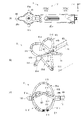
- the tip vicinity structure 6 described above includes the branch point of the catheter shaft 11 (located on the proximal end side of the tip vicinity structure 6) and the vicinity of the tip of the catheter shaft 11 (the tip end described later). a confluence located near the chip 110) and a plurality of (five in this example) branch structures 61a to 61e that are portions that individually connect these branch points and confluence in a curved shape. I'm in. These branch structures 61a to 61e are spaced apart from each other at approximately equal intervals in a plane (XY plane) perpendicular to the axial direction (Z-axis direction) of the catheter shaft 11. As shown in FIG.
- these branch structures 61a to 61e have one or more electrodes 111 (four electrodes 111 in this example) along their curved extending directions. They are spaced apart from each other at predetermined intervals. Each electrode 111 is a ring-shaped electrode.
- a distal tip 110 is arranged at the confluence of the branch structures 61a to 61e (near the distal end of the catheter shaft 11).
- Such electrodes 111 are, as described above, for example, electrodes for potential measurement or cauterization, and examples thereof include aluminum (Al), copper (Cu), SUS, gold (Au), platinum (Pt), and the like. is made of a metal material with good electrical conductivity.
- the tip 110 is made of, for example, the same metal material as the electrodes 111, and is also made of a resin material such as silicone rubber resin or polyurethane.
- each electrode 111 the tip side of the conducting wire 50 described above is electrically connected individually.
- the base end side of each lead wire 50 can be connected to the outside of the electrode catheter 1 through the inside of the catheter shaft 11 and the inside of the handle 12 .
- the base end side of each conductor 50 is taken out from the base end portion (connector portion) of the handle 12 along the Z-axis direction. .
- such a shape of the tip vicinity structure 6 is configured to change (deform) according to a deformation operation to be described later on the handle 12 (deformation operation to the slide mechanism 123 to be described later).
- a non-deployed shape in which the structure 6 near the tip is not expanded along the axial direction (Z-axis direction)
- the shape of the tip vicinity structure 6 changes between the expanded shape (expanded shape: see FIG. 1 and FIG. 7 described later) developed along the direction.
- a “petal shape” an example of a flat shape: see FIG.
- the above-mentioned “basket shape” means, for example, as shown in FIGS. , means that they are of similar shape.
- non-expanded shape (and petal shape) described above corresponds to a specific example of the "first shape” in the present invention.
- developed shape (and basket shape) described above corresponds to a specific example of the "second shape” in the present invention.
- the handle 12 is a portion that is gripped (grasped) by an operator (doctor) when using the electrode catheter 1 .
- the handle 12 has, as shown in FIG. 1, a handle main body 121 attached to the proximal end side of the catheter shaft 11 and a rotary operation section 122 .
- the handle body 121 corresponds to a portion (gripping portion) that an operator actually grips, and has a shape extending along its axial direction (Z-axis direction).
- the handle body 121 is made of a synthetic resin such as polycarbonate or acrylonitrile-butadiene-styrene copolymer (ABS).
- the rotation operation part 122 is a part that is operated during a deflection operation for deflecting (bending) the vicinity of the tip of the catheter shaft 11 (tip flexible part 11A) in both directions.
- the rotary operation part 122 is used together with a pair of deflection wires (not shown) for such a deflection operation.
- the operator of the electrode catheter 1 operates (rotates) the rotary operation section 122 .
- Such a rotary operation unit 122 is configured including a lock mechanism 40 and a rotating plate 41 as shown in FIG.
- Each tip of the pair of deflection wires described above is fixed to the tip side of the catheter shaft 11 (for example, near the tip 110 described above).
- Each proximal end of the pair of deflection wires extends from inside the catheter shaft 11 to inside the handle 12 (inside the handle body 121).
- the rotating plate 41 is rotatable with respect to the handle body 121 about a rotation axis (Y-axis direction: rotation axis Yr to be described later) perpendicular to its axial direction (Z-axis direction). It is a member attached to the The rotating plate 41 corresponds to a portion that is actually operated by the operator during the rotating operation described above, and has a substantially disk-like shape. Specifically, in this example, as indicated by arrows d1a and d1b in FIG. rotation about the rotation axis Yr) is possible.
- the locking mechanism 40 described above is a mechanism for fixing (locking) the rotational position of the rotating plate 41 within the ZY plane.
- knobs 41a and 41b are provided integrally with the rotating plate 41 on the side surface of the rotating plate 41, as shown in FIG.
- the knobs 41a and 41b are arranged in positions that are point-symmetrical about the rotation axis of the rotary plate 41.
- Each of these knobs 41a and 41b corresponds to a portion that is operated (pushed) by the fingers of one hand when the operator rotates the rotary plate 41, for example.
- a rotary plate 41 is made of, for example, the same material (synthetic resin, etc.) as the handle body 121 described above.
- a pair of fasteners are provided on the rotary plate 41 as described above. These fasteners are members (wire fasteners) for individually fixing the proximal ends of the pair of deflection wires described above by screwing or the like. It should be noted that, with these fasteners, it is possible to arbitrarily adjust the retraction length in the vicinity of each proximal end when fixing each proximal end of the pair of deflection wires described above.
- FIG. 2 is an exploded perspective view of an example of the schematic configuration of the handle 12 (the slide mechanism 123 and the like, which will be described later, are omitted).
- FIG. 3 is a schematic plan view (ZY plan view) of a configuration example of a part of the handle 12 shown in FIG. 2 (a configuration example with a handle member 121a described later removed). be.
- FIG. 4 is a cross-sectional view (YZ cross-sectional view) showing a detailed configuration example of a portion of the handle 12 (a portion near the slide mechanism 123, which will be described later).
- FIG. 5 is a cross-sectional view (YZ cross-sectional view) showing a detailed configuration example of another portion of the handle 12 (the portion near the rotation axis Yr shown in FIG. 2).
- the handle body 121 is configured using a pair of handle members 121a and 121b that can be separated along the Y-axis direction.
- the handle body 121 is configured by connecting these handle members 121a and 121b to each other.
- a fixing member 124 is arranged in the handle member 121b for fixing each path of the conducting wire 50 and the deformation wire 60 in the handle body 121.
- the rotation operation unit 122 includes the locking mechanism 40 and the rotating plate 41, the path defining member 42, the rotating member 43, and the ring-shaped member, which are arranged along the rotation axis Yr in the Y-axis direction. 44a, 44b and a connecting member 45 are arranged respectively.
- coupling members 46 and 47 for coupling the proximal end side of the catheter shaft 11 to the handle body 121 are arranged on the distal end side of the rotary operation portion 122, respectively.
- the path defining member 42 is a member that defines a non-rotating path 420 through which the deformation wire 60 passes.
- the non-rotating path 420 is a linear path along the axial direction (Z-axis direction) of the handle 12 as shown in FIG. 3, and passes through the rotation axis Yr as shown in FIG. It is the route.
- the rotating member 43 is a member that rotates within the ZX plane together with the rotating plate 41 .
- the ring-shaped member 44a is arranged between the rotating plate 41 and the path defining member 42
- the ring-shaped member 44b is arranged between the rotating plate 41 and the rotating member 43. ing. As shown in FIG.
- the connecting member 45 includes the rotating plate 41, the path defining member 42, the rotating member 43, and the ring-shaped members 44a and 44b, which are sandwiched between the handle members 121a and 121b together with the locking mechanism 40. It is a member for connecting.
- the path through which the irrigation liquid L flows and the path through which the conductor 50 passes are arranged separately from each other. ing. Specifically, the paths of the liquid L and the conducting wire 50 are separated from each other so as to be opposite to each other with a slide mechanism 123 (such as a knob 123a, which will be described later) interposed therebetween.
- a slide mechanism 123 such as a knob 123a, which will be described later
- the handle 12 (handle body 121) is slidable along the axial direction (Z-axis direction) in the handle body 121 (arrow d3 in FIG. 1). See), a slide mechanism 123 is provided.
- the slide mechanism 123 is operated by the operator (slide operation) during the deformation operation for changing the shape of the tip vicinity structure 6 between the non-expanded shape (petal shape) and the expanded shape (basket shape). ) is performed.
- such a sliding operation of the slide mechanism 123 is performed on rails (openings) in the Z-axis direction formed on the handle body 121 (handle members 121a and 121b). Along the way, it is supposed to be done.
- the slide mechanism 123 is provided with a pair of knobs 123a and 123b, which are actually operated during the deformation operation described above. .
- These knobs 123a and 123b are arranged on both the front side and the back side of the handle body 121 so as to face each other along the Y-axis direction, as shown in FIG.
- the knobs 123a and 123b also slide on both the front side and the back side of the handle body 121, respectively.
- such a slide mechanism 123 can be set to any slide position along the axial direction (Z-axis direction) on the handle body 121 . Therefore, depending on the sliding position of the slide mechanism 123, the shape of the tip vicinity structure 6 during the deformation operation described above is between the non-developed shape (petal shape) and the developed shape (basket shape). Any intermediate shape can be set.
- the tip side of the deformation wire 60 used in such a deformation operation is fixed to the tip vicinity structure 6 (near the tip tip 110 described above).
- the proximal end of the deformation wire 60 is fixed by a slide mechanism 123 in the handle body 121 while being inserted into a rigid tube 125a (lead pipe).
- the rigid tube 125a is fixed to the sleeve 127a on the handle body 121 by a screw 127b formed on the knob 123a, thereby fixing the base end side of the deformation wire 60.
- a rigid tube 125a extends along the axial direction (Z-axis direction) of the handle body 121 and is a highly rigid tube that is difficult to bend.
- the distal end region of the rigid tube 125a is configured to be able to be inserted into the protective tube 125b (protective pipe). Specifically, in the example of the state shown in FIGS. 4 and 5, the distal end side region of the rigid tube 125a is inserted into the protective tube 125b.
- the irrigation liquid L described above flows into the gap between the protective tube 125b and the rigid tube 125a toward the catheter shaft 11 side (the distal end vicinity structure 6).
- a liquid stop member 126 is provided on the base end side of the inflow position of the liquid L with respect to the gap.
- the liquid stop member 126 is a member for preventing leakage of the liquid L for irrigation (leakage from the gap to the base end side).
- a liquid stop member 126 is configured using an O-ring, for example.
- such a liquid stop member 126 may also have a function of adjusting the load of the slide mechanism 123, for example.
- the proximal end side of the protective tube 125b is connected to the irrigation liquid tube 125c via the relay member 128 inside the handle body 121.
- the irrigation liquid L flows toward the distal end side, and the deformation wire 60 is inserted therethrough.
- such an irrigation liquid tube 125 c is connected to the catheter shaft 11 .
- the operator grasps the handle 12 (handle main body 121) with one hand and operates the knob 41a with the fingers of the one hand to move the rotating plate 41 in the direction of the arrow d1a in FIG.
- the knob 41a With the fingers of the one hand to move the rotating plate 41 in the direction of the arrow d1a in FIG.
- the operator can rotate the rotary plate 41 to perform a bidirectional (swing) deflection operation in the catheter shaft 11 .
- the tip flexible portion 11A of the catheter shaft 11 can be bent while the catheter shaft 11 is inserted into the patient's body.
- the direction (deflection direction) can be freely set.
- the electrode catheter 1 is provided with a deflection mechanism for deflecting the tip flexible portion 11A in both directions, so that the shape of the catheter shaft 11 near its tip (tip flexible portion 11A) can be changed. can be inserted into the patient's body.
- the above-described potential measurement and ablation are performed in the flexible tip portion 11A (the tip vicinity structure 6 having a plurality of electrodes 111).
- the above-described irrigation liquid L is supplied to the electrode catheter 1 during such ablation.
- the liquid L is supplied into the handle body 121 from the side surface (liquid inlet) on the base end side of the handle body 121 .
- the liquid L flows out (is jetted) from the vicinity of the tip of the electrode catheter 1 (the vicinity of the above-described branching point in the structure 6 near the tip) to the outside. .
- the liquid L flows out (is jetted) from the vicinity of the tip of the electrode catheter 1 (the vicinity of the above-described branching point in the structure 6 near the tip) to the outside.
- FIG. 6 shows a deformed state (a petal-shaped state described above as an example of the non-deployed shape described above) in the vicinity of the tip of the catheter shaft 11 (the structure 6 near the tip).
- An example of is schematically represented.
- 7 shows another deformed state (the basket shape described above as an example of the expanded shape described above) in the vicinity of the tip of the catheter shaft 11 (the structure 6 near the tip). state) is schematically shown.
- the developed shape (basket shape) shown in FIG. 7 is merely an example, and may be, for example, a shape slightly deflated (distorted) from the shape shown in FIG.
- the distal tip 110 is pulled proximally, so that each of the branch structures 61a to 61e is contracted proximally. That is, the tip vicinity structure 6 becomes the above-described non-expanded shape (in this example, a shape substantially flattened in the XY plane). Specifically, in this example, as shown in FIG. 6B, the shape of the structure 6 near the tip is the above-described petal shape constituted by the branch structures 61a to 61e.
- the tip vicinity structure 6 has the above-described expanded shape (a shape expanded toward the tip side along the Z-axis direction).
- the shape of the tip vicinity structure 6 is the aforementioned basket shape constituted by the respective branched structures 61a to 61e.
- the tip vicinity structure 6 is deformed according to the deformation operation on the slide mechanism 123 .
- FIG. 8 is a schematic plan view (ZX plan view) of a schematic configuration of a catheter (electrode catheter 101) according to a comparative example.
- the electrode catheter 101 of this comparative example includes a catheter shaft 11 having a tip vicinity structure 6 and a handle 102 having a handle main body 103 and a rotary operation section 122 . That is, the electrode catheter 101 of this comparative example is provided with the handle 102 and the handle body 103, respectively, instead of the handle 12 and the handle body 121 in the electrode catheter 1 (see FIG. 1) of the present embodiment. It's becoming
- the following push-in operation section 104 is provided in this handle body 103.
- the proximal end side of the deformation wire 60 taken out from the proximal end of the handle body 103 is attached to the pushing operation portion 104 .
- the push-in operation portion 104 When the operator operates the push-in operation portion 104 along the direction of the arrow d103 (the Z-axis direction: the extending direction of the deformation wire 60), the deformation wire 60 is moved to the handle body 121. operation is performed.
- the tip vicinity structure 6 is deformed in the same manner as in the present embodiment described above. That is, in this comparative example, such an operation in the direction of the arrow d103 with respect to the pressing operation portion 104 corresponds to a deformation operation for deforming the tip vicinity structure 6.
- the conducting wire 50 is also drawn out. That is, since the deformation wire 60 described above is pulled out from the proximal end of the handle body 103, unlike the present embodiment, the conductor wire 50 is not extended from the proximal end of the handle body 103 but from the above-described side surface. are also drawn out.
- the electrode catheter 101 of this comparative example is less convenient to use.
- the handle 12 is provided with a slide mechanism 123 that can slide along the axial direction (Z-axis direction) in the handle body 121 .
- the deformation operation for changing the shape of the tip vicinity structure 6 including the plurality of electrodes 111 between the non-expanded shape (petal shape) and the expanded shape (basket shape) is as follows. That is, in a situation where the operator holds the handle body 121 with one hand, the deformation operation on the slide mechanism 123 can be performed with that one hand (same hand).
- the deformation operation is performed using such a slide mechanism 123, it is possible to obtain the following effects, for example. That is, for example, in a state where the handle 12 is placed on a predetermined table, it is possible to easily perform the above-described rotating operation with the other hand while performing the transforming operation with one hand. Further, unlike the handle body 103 of the comparative example described above, the lead wire 50 can be easily pulled out from the proximal end of the handle body 121 in a state separated from the inflow path of the liquid L for irrigation.
- the tip vicinity structure 6 can be set to any intermediate shape between the non-deployed shape and the developed shape. , it is possible to further improve convenience.
- the distal end of the deformation wire 60 is fixed to the distal end vicinity structure 6, and the proximal end of the deformation wire 60 is inserted through the rigid tube 125a in the handle body 121. Since it is fixed by the slide mechanism 123 in the folded state, it is as follows. That is, since the base end side of the deformation wire 60 is inserted through the rigid tube 125a inside the handle body 121, the deformation wire 60 may be bent inside the handle body 121 when the deformation operation is performed. , is avoided. As a result, the deformation operation can be performed smoothly, and convenience can be further improved.
- the distal end region of the rigid tube 125a is configured to be able to be inserted into the protective tube 125b, and the gap between the protective tube 125b and the rigid tube 125a is filled with , toward the tip-near structure 6, the irrigation liquid L is configured to flow.
- a liquid stop member 126 is provided in the handle body 121 on the base end side of the inflow position of the liquid L with respect to the gap.
- the rotating operation portion 122 which is rotated during the deflecting operation described above, is configured using the rotating plate 41 described above and a member separate from the rotating plate 141 described above. and a path defining member 42 that defines a non-rotating path 420 for the wire 60 to pass through. That is, since the rotating plate 41 and the path defining member 42 are configured using separate members, the non-rotating path 420 is held by the deformation wire 60 even during the rotating operation described above. will be As a result, the rotation operation and the deformation operation can be easily performed with a simple structure, and convenience can be further improved.
- knobs 123a and 123b which are portions to be operated during the deformation operation, are provided on the slide mechanism 123, and these knobs 123a and 123b are attached to the front side and the back side of the handle body 121. Since it is arranged on both sides, it will be as follows. That is, when the slide mechanism 123 slides along the axial direction (Z-axis direction), the knobs 123a and 123b slide on both the front side and the back side of the handle body 121, respectively. In addition, the rotational movements from the knobs 123a and 123b to their intermediate directions cancel each other out. As a result, it is possible to prevent the operation load from being lost during the transforming operation, and as a result, the transforming operation can be performed smoothly, which makes it possible to further improve convenience.
- knob 123a and 123b when only one of the knobs 123a and 123b (knob 123a) is provided on the slide mechanism 123, the following operations are performed. There is a risk that the operating load during the deformation operation will be lost. That is, first, when an operation load F1a is generated from the knob 123a toward the base end during the deforming operation using the knob 123a, the structure 6 near the distal end tries to return to its original shape (basket shape as described above). A restoring force F2 toward the distal end is generated in the deformation wire 60 .
- the shape, arrangement position, size, number, material, etc. of each member described in the above embodiment are not limited, and other shapes, arrangement positions, sizes, numbers, materials, etc. may be used.
- the configuration of the catheter shaft 11 was specifically described, but it is not necessary to include all members, and other members may be included.
- a leaf spring that can be deformed in the bending direction may be provided inside the catheter shaft 11 as a swinging member.
- the arrangement, shape, number (one or more), and the like of each electrode 111 in the vicinity of the tip of the catheter shaft 11 (within the tip vicinity structure 6) are not limited to those described in the above embodiment.
- the shape of the structure 6 near the tip is also limited to the shapes described in the above embodiments (petal shape, basket shape, etc. as an example of the flat shape described above).
- the configuration of the tip vicinity structure 6 itself is not limited to the configuration described in the above embodiment. may be configured.
- the structure of the handle 12 (the handle body 121, the rotation operation section 122, the slide mechanism 123, etc.) was specifically described, but it is not always necessary to include all the members. You may further have a member of.
- the type of shape when deforming the tip vicinity structure 6 is not limited to the case where it can be set to an arbitrary intermediate shape as described in the above embodiment, but also other cases. may That is, for example, instead of an arbitrary intermediate shape, it may be possible to set only a plurality of types of preset intermediate shapes, or, for example, only the two types of shapes, the non-developed shape and the developed shape, described above. may be settable (cannot be set to intermediate shapes).
- the sliding mechanism 123 is provided with a pair of knobs 123a and 123b. You may do so.
- the rotary plate 41 and the path defining member 42 are made of different members. good.
- the configurations of the rigid tube 125a, the protective tube 125b, the liquid stop member 126, etc. are not limited to those described in the above embodiments, and other configurations may be used.
- the shape of the vicinity of the distal end of the catheter shaft 11 is not limited to that described in the above embodiment.
- the electrode catheter 1 of a type (bi-direction type) in which the shape of the vicinity of the distal end of the catheter shaft 11 changes in both directions according to the operation of the rotating plate 41 has been described as an example.
- the electrode catheter may be of a type (single-direction type) in which the shape of the vicinity of the distal end of the catheter shaft 11 changes in one direction according to the operation of the rotating plate 41 . In this case, only one (one) operation wire is provided.
- the electrode catheter 1 (having an irrigation mechanism) that injects the liquid L for irrigation to the outside has been described as an example.
- the present invention may be applied to electrode catheters having no mechanism.
- the electrode catheter 1 for performing potential measurement and cauterization (ablation) was described as an example, but the present invention is not limited to this example. The present invention may be applied.
Landscapes
- Health & Medical Sciences (AREA)
- Surgery (AREA)
- Engineering & Computer Science (AREA)
- Life Sciences & Earth Sciences (AREA)
- Biomedical Technology (AREA)
- Otolaryngology (AREA)
- Nuclear Medicine, Radiotherapy & Molecular Imaging (AREA)
- Plasma & Fusion (AREA)
- Physics & Mathematics (AREA)
- Heart & Thoracic Surgery (AREA)
- Medical Informatics (AREA)
- Molecular Biology (AREA)
- Animal Behavior & Ethology (AREA)
- General Health & Medical Sciences (AREA)
- Public Health (AREA)
- Veterinary Medicine (AREA)
- Media Introduction/Drainage Providing Device (AREA)
Abstract
Priority Applications (4)
| Application Number | Priority Date | Filing Date | Title |
|---|---|---|---|
| PCT/JP2021/003329 WO2022162889A1 (fr) | 2021-01-29 | 2021-01-29 | Cathéter |
| CN202180073703.5A CN116456919A (zh) | 2021-01-29 | 2021-01-29 | 导管 |
| DE112021006955.1T DE112021006955T5 (de) | 2021-01-29 | 2021-01-29 | Katheter |
| JP2022577962A JPWO2022162889A1 (fr) | 2021-01-29 | 2021-01-29 |
Applications Claiming Priority (1)
| Application Number | Priority Date | Filing Date | Title |
|---|---|---|---|
| PCT/JP2021/003329 WO2022162889A1 (fr) | 2021-01-29 | 2021-01-29 | Cathéter |
Publications (1)
| Publication Number | Publication Date |
|---|---|
| WO2022162889A1 true WO2022162889A1 (fr) | 2022-08-04 |
Family
ID=82654322
Family Applications (1)
| Application Number | Title | Priority Date | Filing Date |
|---|---|---|---|
| PCT/JP2021/003329 WO2022162889A1 (fr) | 2021-01-29 | 2021-01-29 | Cathéter |
Country Status (4)
| Country | Link |
|---|---|
| JP (1) | JPWO2022162889A1 (fr) |
| CN (1) | CN116456919A (fr) |
| DE (1) | DE112021006955T5 (fr) |
| WO (1) | WO2022162889A1 (fr) |
Citations (5)
| Publication number | Priority date | Publication date | Assignee | Title |
|---|---|---|---|---|
| JP2002541905A (ja) * | 1999-04-21 | 2002-12-10 | ブロンカス テクノロジーズ, インコーポレイテッド | エネルギーの適用による気道の改変 |
| JP2006505377A (ja) * | 2002-11-11 | 2006-02-16 | アドメデス、シュスラー、ゲゼルシャフト、ミット、ベシュレンクテル、ハフツング | 金属電極 |
| JP2008519669A (ja) * | 2004-11-12 | 2008-06-12 | アスマティックス,インコーポレイテッド | 改善されたエネルギー送達の装置および方法 |
| WO2015141046A1 (fr) * | 2014-03-18 | 2015-09-24 | 日本ライフライン株式会社 | Poignée d'équipement médical et équipement médical |
| WO2017104023A1 (fr) * | 2015-12-16 | 2017-06-22 | 有限会社日本エレクテル | Système de cathéter à ballonnet à haute fréquence |
-
2021
- 2021-01-29 CN CN202180073703.5A patent/CN116456919A/zh active Pending
- 2021-01-29 JP JP2022577962A patent/JPWO2022162889A1/ja active Pending
- 2021-01-29 WO PCT/JP2021/003329 patent/WO2022162889A1/fr active Application Filing
- 2021-01-29 DE DE112021006955.1T patent/DE112021006955T5/de active Pending
Patent Citations (5)
| Publication number | Priority date | Publication date | Assignee | Title |
|---|---|---|---|---|
| JP2002541905A (ja) * | 1999-04-21 | 2002-12-10 | ブロンカス テクノロジーズ, インコーポレイテッド | エネルギーの適用による気道の改変 |
| JP2006505377A (ja) * | 2002-11-11 | 2006-02-16 | アドメデス、シュスラー、ゲゼルシャフト、ミット、ベシュレンクテル、ハフツング | 金属電極 |
| JP2008519669A (ja) * | 2004-11-12 | 2008-06-12 | アスマティックス,インコーポレイテッド | 改善されたエネルギー送達の装置および方法 |
| WO2015141046A1 (fr) * | 2014-03-18 | 2015-09-24 | 日本ライフライン株式会社 | Poignée d'équipement médical et équipement médical |
| WO2017104023A1 (fr) * | 2015-12-16 | 2017-06-22 | 有限会社日本エレクテル | Système de cathéter à ballonnet à haute fréquence |
Also Published As
| Publication number | Publication date |
|---|---|
| JPWO2022162889A1 (fr) | 2022-08-04 |
| CN116456919A (zh) | 2023-07-18 |
| DE112021006955T5 (de) | 2023-11-09 |
Similar Documents
| Publication | Publication Date | Title |
|---|---|---|
| JP6482337B2 (ja) | 医療機器用ハンドルおよび医療機器 | |
| JP5188811B2 (ja) | 把持ツールの遠隔操作のための手動式装置 | |
| TWI583410B (zh) | 醫療器械 | |
| EP3735164B1 (fr) | Sonde médicale pouvant être déviée | |
| EP2591819A1 (fr) | Poignée de commande de dispositif médical avec multiplication de mouvement linéaire | |
| WO2018168024A1 (fr) | Poignée pour dispositif médical et dispositif médical | |
| WO2022162889A1 (fr) | Cathéter | |
| JP6113682B2 (ja) | 医療機器用ハンドルおよび医療機器 | |
| WO2018037594A1 (fr) | Poignée pour dispositif médical, et dispositif médical | |
| JP5360945B1 (ja) | 電極カテーテルおよびその製造方法 | |
| WO2023276080A1 (fr) | Cathéter | |
| JP6166399B1 (ja) | カテーテル | |
| JP5167949B2 (ja) | 内視鏡用高周波処置具 | |
| JP6866110B2 (ja) | 食道温度測定用カテーテル | |
| WO2017119151A1 (fr) | Cathéter et dispositif de cathéter | |
| WO2022137505A1 (fr) | Cathéter à électrode | |
| WO2021220847A1 (fr) | Cathéter pour mesure de potentiel cardiaque | |
| JP6219805B2 (ja) | 電極カテーテル | |
| WO2021166057A1 (fr) | Cathéter à électrode | |
| CN115803076A (zh) | 电致动铰接导管系统 | |
| JP2016135196A (ja) | 医療機器用ハンドルおよび医療機器 |
Legal Events
| Date | Code | Title | Description |
|---|---|---|---|
| 121 | Ep: the epo has been informed by wipo that ep was designated in this application |
Ref document number: 21922904 Country of ref document: EP Kind code of ref document: A1 |
|
| ENP | Entry into the national phase |
Ref document number: 2022577962 Country of ref document: JP Kind code of ref document: A |
|
| WWE | Wipo information: entry into national phase |
Ref document number: 202180073703.5 Country of ref document: CN |
|
| WWE | Wipo information: entry into national phase |
Ref document number: 18252810 Country of ref document: US |
|
| WWE | Wipo information: entry into national phase |
Ref document number: 112021006955 Country of ref document: DE |
|
| 122 | Ep: pct application non-entry in european phase |
Ref document number: 21922904 Country of ref document: EP Kind code of ref document: A1 |