WO2022158262A1 - センサシステム、車両の制御方法および車両 - Google Patents
センサシステム、車両の制御方法および車両 Download PDFInfo
- Publication number
- WO2022158262A1 WO2022158262A1 PCT/JP2021/048375 JP2021048375W WO2022158262A1 WO 2022158262 A1 WO2022158262 A1 WO 2022158262A1 JP 2021048375 W JP2021048375 W JP 2021048375W WO 2022158262 A1 WO2022158262 A1 WO 2022158262A1
- Authority
- WO
- WIPO (PCT)
- Prior art keywords
- vehicle
- vehicle speed
- sensor
- cleaner
- predetermined value
- Prior art date
- Legal status (The legal status is an assumption and is not a legal conclusion. Google has not performed a legal analysis and makes no representation as to the accuracy of the status listed.)
- Ceased
Links
Images




Classifications
-
- B—PERFORMING OPERATIONS; TRANSPORTING
- B60—VEHICLES IN GENERAL
- B60W—CONJOINT CONTROL OF VEHICLE SUB-UNITS OF DIFFERENT TYPE OR DIFFERENT FUNCTION; CONTROL SYSTEMS SPECIALLY ADAPTED FOR HYBRID VEHICLES; ROAD VEHICLE DRIVE CONTROL SYSTEMS FOR PURPOSES NOT RELATED TO THE CONTROL OF A PARTICULAR SUB-UNIT
- B60W50/00—Details of control systems for road vehicle drive control not related to the control of a particular sub-unit, e.g. process diagnostic or vehicle driver interfaces
- B60W50/02—Ensuring safety in case of control system failures, e.g. by diagnosing, circumventing or fixing failures
-
- B—PERFORMING OPERATIONS; TRANSPORTING
- B60—VEHICLES IN GENERAL
- B60W—CONJOINT CONTROL OF VEHICLE SUB-UNITS OF DIFFERENT TYPE OR DIFFERENT FUNCTION; CONTROL SYSTEMS SPECIALLY ADAPTED FOR HYBRID VEHICLES; ROAD VEHICLE DRIVE CONTROL SYSTEMS FOR PURPOSES NOT RELATED TO THE CONTROL OF A PARTICULAR SUB-UNIT
- B60W60/00—Drive control systems specially adapted for autonomous road vehicles
-
- G—PHYSICS
- G01—MEASURING; TESTING
- G01C—MEASURING DISTANCES, LEVELS OR BEARINGS; SURVEYING; NAVIGATION; GYROSCOPIC INSTRUMENTS; PHOTOGRAMMETRY OR VIDEOGRAMMETRY
- G01C21/00—Navigation; Navigational instruments not provided for in groups G01C1/00 - G01C19/00
- G01C21/26—Navigation; Navigational instruments not provided for in groups G01C1/00 - G01C19/00 specially adapted for navigation in a road network
- G01C21/34—Route searching; Route guidance
- G01C21/36—Input/output arrangements for on-board computers
-
- G—PHYSICS
- G08—SIGNALLING
- G08G—TRAFFIC CONTROL SYSTEMS
- G08G1/00—Traffic control systems for road vehicles
- G08G1/16—Anti-collision systems
Definitions
- the present invention relates to a sensor system, a vehicle control method, and a vehicle.
- a cleaner system equipped with a cleaner is known from Patent Document 1 and the like.
- Patent Document 1 when dirt adheres to the sensor, the cleaner is operated to try to remove the dirt, and when the dirt on the sensor still does not come off, the automatic operation mode is switched to the manual operation mode.
- the vehicle cannot travel in the automatic operation mode, and it is assumed that the vehicle cannot travel in the automatic operation mode frequently.
- the original detection sensitivity of the sensor has not been achieved, for example, there will be no problem with sensing at short distances, but there will be no problem with the execution of the low-speed automatic driving mode. Considering this situation, I realized that there is room to secure a longer distance that can be driven in automatic driving mode.
- the present invention provides a sensor system, a vehicle control method, and a vehicle that can ensure a long driving distance in automatic driving mode.
- a sensor system comprises: A sensor system mounted on a vehicle capable of traveling in an autonomous driving mode, the sensor acquiring information from the outside of the vehicle; an abnormality determination unit that determines an abnormality caused by a scratch or dirt based on the detection result of the sensor; a vehicle speed limit setting unit that outputs a first maximum vehicle speed signal indicating a first maximum vehicle speed in the automatic driving mode to the vehicle according to a determination result of the abnormality determination unit.
- the vehicle control unit determines that mud or the like causes an abnormality in the detection result of the sensor
- the vehicle speed limit setting unit outputs a maximum vehicle speed signal to the vehicle control unit. can execute the automatic driving mode below the first maximum vehicle speed. As a result, it is possible to secure a long distance that the vehicle can travel in the automatic driving mode.
- a vehicle control method includes: Running in automatic driving mode using a sensor system that includes a sensor that acquires information on the outside of the vehicle and an abnormality determination unit that determines that an abnormality has occurred in the detection result of the sensor due to scratches or dirt.
- a possible vehicle control method comprising: The first maximum vehicle speed in the automatic driving mode is set according to the determination result of the abnormality determination section.
- the vehicle control unit determines that mud or the like causes an abnormality in the detection result of the sensor
- the maximum vehicle speed in the automatic driving mode is set according to the determination result of the abnormality determination unit.
- a vehicle includes: A vehicle capable of automated driving, an automatic driving execution unit that drives the vehicle in an automatic driving mode; a sensor that acquires information outside the vehicle; an abnormality determination unit that determines that an abnormality caused by a scratch or dirt has occurred in the detection result of the sensor; and a vehicle speed limit setting unit that generates a first maximum vehicle speed signal indicating a first maximum vehicle speed in the automatic driving mode according to a determination result of the abnormality determination unit.
- the vehicle control unit determines that mud or the like causes an abnormality in the detection result of the sensor
- the vehicle speed limit setting unit outputs a maximum vehicle speed signal to the vehicle control unit. can execute the automatic driving mode below the first maximum vehicle speed. As a result, it is possible to secure a long distance that the vehicle can travel in the automatic driving mode.
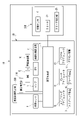
- FIG. 1 is a system block diagram of a vehicle;
- FIG. It is a sectional view of a camera. 4 shows an image captured by a camera in normal operation; The image which the camera imaged at the time of abnormality is shown.
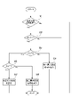
- 4 is a flowchart of processing executed by a vehicle speed limit setting unit;
- FIG. 5 is a flow chart of a method according to a modification of the invention, which is executed by a vehicle speed limit setting unit;
- FIG. It is a system block diagram of the vehicle concerning the first modification of the present invention.
- FIG. 10 is a system block diagram of a vehicle according to a second modified example of the invention.
- the terms “left-right direction”, “front-rear direction”, and “vertical direction” will be referred to as appropriate. These directions are relative directions set for the vehicle.
- the “vertical direction” is a direction including the “upward direction” and the “downward direction”.
- “Fore-and-aft direction” is a direction that includes “forward direction” and “rearward direction.”
- a “left-right direction” is a direction including a “left direction” and a “right direction.”
- FIG. 1 is a system block diagram of a vehicle 1.
- the vehicle system 2 includes a vehicle control unit 3, an internal sensor 5, a lamp 7, an HMI 8 (Human Machine Interface), a GPS 9 (Global Positioning System), a wireless communication unit 10, a map and an information storage unit 11 .
- the vehicle system 2 includes a steering actuator 12 , a steering device 13 , a brake actuator 14 , a brake device 15 , an accelerator actuator 16 and an accelerator device 17 .
- the vehicle control unit 3 is composed of an electronic control unit (ECU).
- the vehicle control unit 3 includes a processor such as a CPU (Central Processing Unit), a ROM (Read Only Memory) storing various vehicle control programs, and a RAM (Random Access Memory) temporarily storing various vehicle control data. It is composed of The processor develops on the RAM programs designated from various vehicle control programs stored in the ROM, and is configured to execute various processes in cooperation with the RAM.
- the vehicle control unit 3 is configured to control travel of the vehicle 1 .
- the internal sensor 5 is a sensor capable of acquiring information on the own vehicle.
- the internal sensor 5 is, for example, at least one of an acceleration sensor, a speed (vehicle speed) sensor, a wheel speed sensor, a gyro sensor, and the like.
- the internal sensor 5 is configured to acquire information about the vehicle including the running state of the vehicle 1 and output the information to the vehicle control unit 3 .
- the internal sensors 5 include a seating sensor that detects whether or not the driver is sitting in the driver's seat, a face direction sensor that detects the direction of the driver's face, and a human sensor that detects whether or not there is a person inside the vehicle. may
- the lamps 7 include head lamps and position lamps provided at the front of the vehicle 1, rear combination lamps provided at the rear of the vehicle 1, turn signal lamps provided at the front or side of the vehicle, pedestrians and drivers of other vehicles. It is at least one of various lamps or the like for informing the driver of the situation of the own vehicle.
- the HMI 8 is composed of an input section that receives input operations from the driver and an output section that outputs driving information and the like to the driver.
- the input unit includes a steering wheel, an accelerator pedal, a brake pedal, an operation mode switch for switching the operation mode of the vehicle 1, and the like.
- the output unit is a display that displays various running information.
- the GPS 9 is configured to acquire current position information of the vehicle 1 and output the acquired current position information to the vehicle control unit 3 .
- the wireless communication unit 10 is configured to receive travel information of other vehicles around the vehicle 1 from other vehicles and to transmit travel information of the vehicle 1 to the other vehicles (vehicle-to-vehicle communication). Further, the wireless communication unit 10 is configured to receive infrastructure information from infrastructure equipment such as traffic lights and marker lights, and to transmit travel information of the vehicle 1 to the infrastructure equipment (road-to-vehicle communication).
- the map information storage unit 11 is an external storage device such as a hard disk drive storing map information, and is configured to output the map information to the vehicle control unit 3 .
- the vehicle control unit 3 When the vehicle 1 runs in the automatic driving mode, the vehicle control unit 3 generates at least a steering control signal, an accelerator control signal, and a brake control signal based on the running state information, the surrounding environment information, the current position information, the map information, and the like. Automatically generate one.
- the steering actuator 12 is configured to receive a steering control signal from the vehicle control unit 3 and control the steering device 13 based on the received steering control signal.
- the brake actuator 14 is configured to receive a brake control signal from the vehicle control unit 3 and control the brake device 15 based on the received brake control signal.
- the accelerator actuator 16 is configured to receive an accelerator control signal from the vehicle control unit 3 and control the accelerator device 17 based on the received accelerator control signal.
- the running of the vehicle 1 is automatically controlled by the vehicle system 2 .
- the vehicle control unit 3 when the vehicle 1 runs in manual operation mode, the vehicle control unit 3 generates a steering control signal, an accelerator control signal, and a brake control signal according to the driver's manual operation of the accelerator pedal, brake pedal, and steering wheel.
- the steering control signal, the accelerator control signal and the brake control signal are generated by the driver's manual operation, so that the driving of the vehicle 1 is controlled by the driver.
- the operation mode consists of an automatic operation mode and a manual operation mode.
- the automatic driving mode consists of a fully automatic driving mode, an advanced driving assistance mode, and a driving assistance mode.
- the vehicle system 2 In the fully automatic driving mode, the vehicle system 2 automatically performs all driving control including steering control, brake control and accelerator control, and the driver is not in a state where the vehicle 1 can be driven.
- the vehicle system 2 In the advanced driving assistance mode, the vehicle system 2 automatically performs all driving control including steering control, brake control and accelerator control, and the driver does not drive the vehicle 1 although the vehicle 1 is ready to be driven.
- the vehicle system 2 In the driving assistance mode, the vehicle system 2 automatically performs part of driving control out of steering control, brake control, and accelerator control, and the driver drives the vehicle 1 under the driving assistance of the vehicle system 2 .
- the vehicle system 2 In the manual driving mode, the vehicle system 2 does not automatically perform travel control, and the driver drives the vehicle 1 without the driving assistance of the vehicle system 2 .
- the driving mode of the vehicle 1 may be switched by operating a driving mode changeover switch.
- the vehicle control unit 3 changes the driving mode of the vehicle 1 into four driving modes (fully automatic driving mode, advanced driving support mode, driving support mode, manual driving mode) according to the driver's operation of the driving mode switch. ).
- the driving mode of the vehicle 1 is automatically set based on information about drivable sections in which the autonomous vehicle can travel, prohibited sections in which the autonomous vehicle is prohibited from traveling, or information about external weather conditions. may be switched.
- the vehicle control unit 3 switches the driving mode of the vehicle 1 based on these pieces of information.
- the driving mode of the vehicle 1 may be automatically switched by using a seating sensor, a face orientation sensor, or the like of the internal sensors 5 . In this case, the vehicle control unit 3 switches the driving mode of the vehicle 1 based on the output signals from the seating sensor and face direction sensor.
- the vehicle system 2 further includes a sensor system 20 as shown in FIG.
- the sensor system 20 includes an external sensor 6 (sensor), an abnormality determination section 21 , a vehicle speed limit setting section 22 , a driving mode acquisition section 23 , a cleaner 24 and a cleaner control section 25 .
- the external sensor 6 is a sensor capable of acquiring information on the outside of the own vehicle 1 .
- the external sensor 6 is, for example, at least one of a camera, radar, LiDAR, gating camera, and the like.
- the external sensor 6 acquires information on the outside of the own vehicle including the surrounding environment of the vehicle 1 (other vehicles, pedestrians, road shape, traffic signs, obstacles, etc.) and outputs the information to the vehicle control unit 3.
- the external sensor 6 may include a weather sensor that detects weather conditions, an illuminance sensor that detects the illuminance of the surrounding environment of the vehicle 1, or the like.
- the external sensor 6 is configured to acquire at least one information on the front, sides, and rear of the vehicle 1 .
- the camera is, for example, a camera including an imaging device 31 such as a CCD (Charge-Coupled Device) or CMOS (Complementary MOS).
- the camera is a camera that detects visible light, an infrared camera that detects infrared light, or a gating camera (range gate camera).
- the radar is millimeter wave radar, microwave radar, or the like.
- LiDAR is an abbreviation for Light Detection and Ranging or Laser Imaging Detection and Ranging.
- LiDAR is a sensor that generally emits invisible light in front of it and acquires information such as the distance to an object, the shape of the object, the material of the object, and the color of the object based on the emitted light and the returned light.
- the present embodiment will be described using a camera as an example of the external sensor 6 .
- the driving mode acquisition unit 23 acquires from the vehicle control unit 3 an automatic driving signal indicating that the vehicle 1 is running in the automatic driving mode. In other words, when the vehicle 1 is running in the automatic driving mode, the driving mode acquisition unit 23 acquires the automatic driving signal from the vehicle control unit 3 .
- the cleaner 24 is a device that cleans the area detected by the external sensor 6 by spraying a cleaning medium such as air or water onto mud or dust adhering to the external sensor 6 , or operates a wiper to detect the external sensor 6 . It is a device that cleans the part to be cleaned.
- a cleaner control section 25 controls the operation of the cleaner 24 based on a command from the vehicle speed limit setting section 22 .
- FIG. 2 is a cross-sectional view of the camera 6.
- the camera 6 includes an imaging element 31, a substrate 32 on which the imaging element 31 is mounted, an inner lens 33 for condensing external light onto the imaging element 31, an outer cover 34, and a housing 35.
- the outer cover 34 is a transparent member and forms a closed space together with the housing 35 .
- the imaging device 31, substrate 32, and inner lens 33 are housed in this sealed space.
- the abnormality determination unit 21 determines that an abnormality caused by scratches or stains has occurred based on the detection result of the external sensor 6 .
- dirt, dust, leaves, insects, and the like adhere to the outer cover 34 .
- the outer cover 34 may be scratched or cracked due to contact with obstacles or stepping stones, deterioration over time, or the like.
- the inner lens 33 may also crack due to aged deterioration or the like.
- the inner surface of the inner lens 33 may become cloudy or water droplets may adhere.
- the inner lens 33 may be deformed due to temperature change or stress, and this deformation may affect the polarized light, resulting in a reduction in the output of linearly polarized laser light. Light entering the imaging element 31 from the outside passes through the outer cover 34 and the inner lens 33 . If the outer cover 34 and the inner lens 33 are scratched or soiled, the detection result of the camera 6 will be abnormal.
- FIG. 3 shows an image captured by the camera 6 when the outer cover 34 and the inner lens 33 are not scratched or dusty.
- FIG. 4 shows an image captured by the camera 6 when mud adheres to the outer cover 34 . Note that in FIGS. 3 and 4, the pixels 41 are drawn much coarser than they actually are for the convenience of drawing.
- the camera 6 forms an image 40 consisting of a plurality of pixels 41, as shown in FIGS.
- the camera 6 decomposes a predetermined area within the angle of view of the camera 6 of the vehicle 1 into arbitrary minute elements, and obtains information such as the wavelength (color) of light coming from each minute element and the intensity of the light at that wavelength. Acquired by the corresponding image sensor 31 .
- Information on minute elements acquired by one imaging device 31 is output as a pixel 41 .
- the pixel 41 contains information such as brightness and color according to the brightness and the wavelength of light acquired by the imaging device 31 .
- the camera integrates pixels 41 output from the respective imaging elements 31 to generate an image 40 and outputs the generated image 40 to the vehicle control unit 3 .
- reference symbol D indicates a pixel for which an abnormality has occurred in the detection result.
- the abnormality determination unit 21 determines whether or not an abnormality has occurred in the detection result of the minute element by determining whether the change in the information of the minute element is equal to or less than a predetermined threshold over a predetermined period of time while the vehicle 1 is running. judge. In this example, when the change in the information of the minute element (change in pixel) is equal to or less than a predetermined threshold value over a predetermined period of time while the vehicle 1 is running, the abnormality determination unit 21 detects an abnormality in the detection result of the minute element. determined to be
- the abnormality determination unit 21 does not determine abnormality of the external sensor 6 caused by an abnormality of an electric circuit that configures the external sensor 6 or the like.
- the abnormality determination unit 21 referred to here is caused by scratches, cracks, dust, mud, sand, water, insects, leaves, etc. adhering to optical members such as the outer cover 34 and the inner lens 33 that constitute the external sensor 6. An abnormality of the external sensor 6 that occurs is targeted for determination.
- LiDAR also decomposes a predetermined area within the angle of view outside the vehicle 1 into arbitrary minute elements, irradiates each minute element with a laser, and obtains the reflection intensity, frequency, and return time (TOF (time off of flight)).
- the LiDAR includes a transmitter that transmits a laser, a receiver that receives the laser reflected by an object in front of the LiDAR, a housing that accommodates the transmitter and the receiver, and an outer cover. If the outer cover is stained with mud, dust, scratches, etc., the information obtained from the specific minute area will not change even if the vehicle 1 is running.
- the abnormality determination unit 21 determines that an abnormality has occurred in the detection result of the minute element when the change in information obtained from the minute element over a predetermined period of time is equal to or less than a predetermined threshold even when the vehicle 1 is running. determine that there is
- Millimeter-wave radar also divides a predetermined area within the angle of view outside the vehicle 1 into arbitrary minute elements, and irradiates each minute element with millimeter waves to obtain the reflection intensity, frequency, and return time ( TOF).
- a millimeter-wave radar includes a transmitting section that transmits millimeter waves, a receiving section that receives millimeter waves that have been reflected by an object in front of the millimeter-wave radar, a housing that accommodates the transmitting section and the receiving section, and an outer cover. If the outer cover is stained with mud, dust, scratches, etc., the information obtained from the specific minute area will not change even if the vehicle 1 is running.
- the abnormality determination unit 21 determines that an abnormality has occurred in the detection result of the minute element when the change in information obtained from the minute element over a predetermined period of time is equal to or less than a predetermined threshold even when the vehicle 1 is running. determine that there is
- the vehicle speed limit setting unit 22 outputs a first maximum vehicle speed signal indicating the first maximum vehicle speed V1 in the automatic driving mode to the vehicle control unit 3 of the vehicle 1 according to the determination result of the abnormality determination unit 21. More specifically, the vehicle speed limit setting unit 22 executes the processing shown in FIG. FIG. 5 is a flowchart of processing executed by the vehicle speed limit setting unit 22. As shown in FIG.
- the vehicle speed limit setting unit 22 first determines whether or not the automatic driving signal is acquired from the vehicle control unit 3 (step S01). If the vehicle speed limit setting unit 22 has not acquired the automatic driving signal (step S01: No), the vehicle speed limit setting unit 22 ends the processing.
- step S02 it is determined whether the index S is equal to or greater than the first predetermined value T1 (step S02).
- the index S represents the ratio of the total sum Sd to the total number Smax of all minute elements forming the predetermined region, where Sd is the sum of minute elements determined to be abnormal in the detection result by the abnormality determination unit 21. is an indicator.
- step S02: Yes the vehicle speed limit setting unit 22 determines that the index S: 0.25 is equal to or greater than the first predetermined value T1: 0.15 (step S02: Yes), and proceeds to step S03. On the other hand, if the index S is less than the first predetermined value T1 (step S02: No), the process ends.
- step S03 the vehicle speed limit setting unit 22 determines whether or not the calculated index S is equal to or greater than the second predetermined value T2, which is greater than the first predetermined value T1.
- the vehicle speed limit setting unit 22 determines that the index S is not equal to or greater than the second predetermined value T2 (step S03: No), and the first maximum vehicle speed in the automatic driving mode.
- a first maximum vehicle speed signal indicating V1 is output to the vehicle control unit 3 (step S04), and the process ends.
- the first maximum vehicle speed V1 in the automatic driving mode is the maximum speed of the vehicle 1 that is set when the vehicle 1 travels in the automatic driving mode.
- the vehicle speed limit setting unit 22 can output a first maximum vehicle speed signal indicating 20 km/h as the maximum vehicle speed.
- the first maximum vehicle speed signal indicating the first maximum vehicle speed V1 in the automatic driving mode is output to the vehicle 1 according to the determination result of the abnormality determination unit 21. .
- the vehicle control unit 3 executes the automatic driving mode based on the output of an external sensor 6 such as a camera.
- an external sensor 6 such as a camera.
- the vehicle control unit 3 may find it difficult to execute the automatic driving mode at normal speed.
- the vehicle speed limit setting unit 22 outputs the maximum vehicle speed to the vehicle control unit 3,
- the vehicle control unit 3 executes the automatic driving mode at the first maximum vehicle speed V1 or less. As a result, it is possible to ensure a long distance that the vehicle 1 can travel in the automatic driving mode.
- the external sensor 6 has a transmitter that emits a signal and/or a receiver that receives the signal.
- the vehicle speed limit setting unit 22 outputs the first maximum vehicle speed signal. is configured to output
- step S03 determines that the index S is equal to or greater than the second predetermined value T2 (step S03: Yes). It is determined whether or not it is equal to or greater than a large third predetermined value T3 (step S05).
- the vehicle speed limit setting unit 22 sets the second maximum vehicle speed V2 indicating the second maximum vehicle speed V2 during the automatic driving mode.
- a maximum vehicle speed signal is output to the vehicle control unit 3 (step S06), and the process ends.
- the second maximum vehicle speed V2 is a value smaller than the first maximum vehicle speed V1.
- step S ⁇ b>06 the vehicle speed limit setting unit 22 outputs to the vehicle control unit 3 a second maximum vehicle speed signal indicating a second maximum vehicle speed V ⁇ b>2 that is lower than the first maximum vehicle speed V ⁇ b>1 .
- the vehicle control unit 3 executes the automatic driving mode at a lower speed so that the execution of the automatic driving mode is not hindered.
- the maximum vehicle speed By gradually decreasing the maximum vehicle speed in accordance with the increase in the number of minute elements with abnormal detection results, the number of minute elements with abnormal detection results exceeding a predetermined value is reduced. Sometimes extremely low maximum vehicle speed is not set suddenly. Therefore, convenience for users such as the owner of the vehicle 1 and the driver of the vehicle is enhanced.
- step S05 When it is determined in step S05 that the index S is equal to or greater than the third predetermined value T3 (step S05: Yes), the vehicle speed limit setting unit 22 cancels the destination currently set in the vehicle control unit 3 and sets it in advance.
- the predetermined destination is set and the process ends.
- the predetermined destination is, for example, a vehicle maintenance shop, a car dealer, or the user's home.
- the predetermined destination may be configured to be determined by the provider of the sensor system 20, the provider (car manufacturer) of the vehicle 1, or the user of the vehicle.
- step S ⁇ b>07 vehicle speed limit setting unit 22 moves vehicle 1 to a predetermined destination in order to have external sensor 6 inspected.
- the vehicle speed limit setting unit 22 may be configured to output a signal to stop the vehicle in addition to causing the vehicle control unit 3 to set a predetermined destination.
- the vehicle can be stopped and an inspection of the external sensor 6 can be urged on the spot, or an act such as calling an inspector can be urged.
- the example in which the index S is compared with the first predetermined value T1 and then with the second predetermined value T2 or the third predetermined value T3 has been described. may be configured to be compared only with the first predetermined value T1.
- the vehicle speed limit setting unit 22 may be configured to compare the index S with the first predetermined value T1 and the second predetermined value T2.
- the vehicle speed limit setting unit 22 may be configured to compare the index S with the first predetermined value T1 and the third predetermined value T3.
- the third predetermined value T3 may be set to a value smaller than the second predetermined value T2.
- the above-described first predetermined value T1, second predetermined value T2, and third predetermined value T3 become smaller values in this order.
- the vehicle speed limit setting unit 22 may be configured to execute the processing shown in FIG.
- FIG. 6 is a flow chart of a method according to a modification of the invention, which is executed by the vehicle speed limit setting unit 22.
- the vehicle speed limit setting unit 22 determines whether or not the automatic driving signal has been acquired from the vehicle control unit 3 (step S11), and further determines whether the index S is equal to or greater than the first predetermined value T1. It is determined whether or not (step S12). Since these steps S11 and S12 are the same as steps S01 and S02 described above, description thereof will be omitted.
- step S12 when it is determined that the index S is equal to or greater than the first predetermined value T1 (step S12: Yes), the vehicle speed limit setting unit 22 outputs the first maximum vehicle speed V1 to the vehicle control unit 3 (step S13 ), and further outputs an activation signal to the cleaner control section 25 to activate the cleaner 24 (step S14).
- the cleaner may be activated once or multiple times.
- the vehicle speed limit setting unit 22 acquires a signal indicating that the operation of the cleaner 24 has been completed (step S15)
- the vehicle speed limit setting unit 22 acquires again from the abnormality determination unit 21 the number of minute elements for which an abnormality has occurred in the detection result. is calculated, and it is determined whether or not the index S is equal to or greater than the first predetermined value T1 (step S16).
- the vehicle speed limit setting unit 22 When it is determined that the index S has decreased to less than the first predetermined value T1 after the cleaner 24 has been operated (step S16: No), the vehicle speed limit setting unit 22 outputs a cancellation signal for canceling the setting of the first maximum vehicle speed V1 to the vehicle. Output to the control unit 3 (step S16). That is, when the dirt and dust adhering to the outer cover 34 are removed by the operation of the cleaner 24, it becomes unnecessary to limit the maximum vehicle speed in the automatic driving mode. , the vehicle control unit 3 can execute the automatic driving mode without any restriction on the maximum vehicle speed.
- step S16: Yes if it is determined that the index S has remained equal to or greater than the first predetermined value T1 even after the cleaner 24 has been activated (step S16: Yes), the vehicle speed limit setting unit 22 is currently set in the vehicle control unit 3. The destination is canceled and set to a predetermined destination, and the processing ends. In other words, if the number of minute elements with abnormal detection results does not decrease even when the cleaner 24 operates, it is assumed that the outer cover 34 and the inner lens 33 are damaged or cracked. Therefore, in the present embodiment, when it is determined that the index S is maintained at or above the first predetermined value T1 even after the cleaner 24 has been activated, the vehicle 1 can be moved to a maintenance shop or the like for inspection.
- the sensor system 20 has the vehicle speed limit setting unit 22 and the abnormality determination unit 21, and the vehicle speed limit setting unit 22 of the sensor system 20 outputs a maximum vehicle speed signal to the vehicle control unit 3.
- the present invention is not limited to this example.
- FIG. 7 is a system block diagram of vehicle 1A according to the first modified example of the present invention.
- a vehicle 1A has a vehicle system 2A and a sensor system 20A.
- the vehicle system 2A has a vehicle control section 3 and a vehicle speed limit setting section 22A.
- a sensor system 20 ⁇ /b>A has an external sensor 6 , an abnormality determination section 21 , a cleaner 24 and a cleaner control section 25 .
- the abnormality determination unit 21 of the sensor system 20A outputs the number of minute elements for which an abnormality has occurred in the detection result to the vehicle system 2A
- the vehicle speed limit setting unit 22A of the vehicle system 2A calculates the index S to obtain a predetermined value. may be configured to be compared with
- FIG. 8 is a system block diagram of a vehicle 1B according to a second modified example of the invention.
- the vehicle 1B has a vehicle system 2B and a sensor system 20B.
- the vehicle system 2B has a vehicle speed limit setting section 22B and an abnormality determination section 21B.
- a sensor system 20B has an external sensor 6, a cleaner 24 and a cleaner controller 25.
- FIG. In this case, the output of the external sensor 6 of the sensor system 20B is output to the vehicle system 2B, the abnormality determination unit 21 of the vehicle system 2B calculates the number of minute elements for which abnormality has occurred in the detection result, and the vehicle speed of the vehicle system 2B is calculated.
- the limit setting unit 22B may be configured to calculate the index S and compare it with a predetermined value.
- the vehicle not the sensor system, may be configured to set the first maximum vehicle speed in the automatic driving mode according to the determination result of the abnormality determination unit. That is, the present invention uses a sensor system 20 that includes a sensor that acquires information on the outside of the vehicle, and an abnormality determination unit 21 that determines whether an abnormality has occurred in the detection result of the sensor due to damage or dirt. , is a control method for a vehicle that can run in the automatic driving mode, and can also be expressed as a vehicle control method in which the first maximum vehicle speed in the automatic driving mode is set according to the determination result of the abnormality determination unit 21.
- the present invention is a vehicle capable of automatic operation, an automatic operation execution unit that drives the vehicle in an automatic operation mode, a sensor that acquires information on the outside of the vehicle, and a detection result of the sensor due to scratches or dirt.
- An abnormality determination unit 21 that determines that an abnormality has occurred, and a vehicle speed limit setting unit 22 that generates a first maximum vehicle speed signal indicating the first maximum vehicle speed in the automatic driving mode according to the determination result of the abnormality determination unit 21. and can also be expressed as a vehicle.
- the vehicle driving mode includes a fully automatic driving mode, an advanced driving support mode, a driving support mode, and a manual driving mode, but the vehicle driving mode includes these four modes.
- the operating modes of the vehicle may include at least one of these four modes. For example, only one of the driving modes of the vehicle may be executable.
- classification of vehicle driving modes and the display format may be changed as appropriate in accordance with the laws and regulations related to automated driving in each country.
- definitions of "fully automatic driving mode”, “advanced driving support mode”, and “driving support mode” described in the description of the present embodiment are only examples, and laws and ordinances related to automatic driving in each country In keeping with the rules, these definitions may be changed accordingly.
- a sensor system a vehicle control method, and a vehicle are provided that can ensure a long driving distance in automatic driving mode.
Landscapes
- Engineering & Computer Science (AREA)
- Automation & Control Theory (AREA)
- Radar, Positioning & Navigation (AREA)
- Remote Sensing (AREA)
- Physics & Mathematics (AREA)
- General Physics & Mathematics (AREA)
- Human Computer Interaction (AREA)
- Transportation (AREA)
- Mechanical Engineering (AREA)
- Traffic Control Systems (AREA)
- Control Of Vehicle Engines Or Engines For Specific Uses (AREA)
Abstract
Description
自動運転モードで走行可能な車両に搭載されるセンサシステムであって
車両の外部の情報を取得するセンサと、
前記センサの検出結果に基づき傷または汚れに起因する異常が生じていることを判定する異常判定部と、
前記異常判定部の判定結果に応じて、前記車両に前記自動運転モード時の第一最大車速を示す第一最大車速信号を出力する車速制限設定部と、を有する、センサシステム。
車両の外部の情報を取得するセンサと、前記センサの検出結果に傷または汚れに起因する異常が生じていることを判定する異常判定部と、を含むセンサシステムを用いた、自動運転モードで走行可能な車両の制御方法であって、
前記異常判定部の判定結果に応じて、前記自動運転モード時の第一最大車速が設定される。
自動運転可能な車両であって、
自動運転モードで車両を走行させる自動運転実行部と、
車両の外部の情報を取得するセンサと、
前記センサの検出結果に傷または汚れに起因する異常が生じていることを判定する異常判定部と、
前記異常判定部の判定結果に応じて、前記自動運転モード時の第一最大車速を示す第一最大車速信号を生成する車速制限設定部と、を有する。
図1は、車両1のシステムブロック図である。図1に示すように、車両システム2は、車両制御部3と、内部センサ5と、ランプ7と、HMI8(Human Machine Interface)と、GPS9(Global Positioning System)と、無線通信部10と、地図情報記憶部11とを備えている。さらに、車両システム2は、ステアリングアクチュエータ12と、ステアリング装置13と、ブレーキアクチュエータ14と、ブレーキ装置15と、アクセルアクチュエータ16と、アクセル装置17とを備えている。
レーダは、ミリ波レーダ、マイクロ波レーダ等である。
LiDARとは、Light Detection and RangingまたはLaser Imaging Detection and Rangingの略語である。LiDARは、一般にその前方に非可視光を出射し、出射光と戻り光とに基づいて、物体までの距離、物体の形状、物体の材質、物体の色などの情報を取得するセンサである。
なお、以降の説明ではカメラを外部センサ6の一例として取り上げて本実施形態を説明する。
具体的には、アウタカバー34に泥や埃、木の葉や虫などが付着する。あるいは障害物や飛び石との接触や経年劣化などによりアウタカバー34に傷や亀裂が生じることがある。あるいは、インナレンズ33にも経年劣化などにより亀裂が生じることがある。あるいはインナレンズ33の内面へくもりが生じたり、水滴が付着することがある。あるいは、温度変化や応力によりインナレンズ33の内部に変形が生じ、この変形により偏光の影響が生じ、直線偏光であるレーザ光の出力が低下することがある。
外部から撮像素子31に入射する光は、アウタカバー34やインナレンズ33を通過する。これらアウタカバー34やインナレンズ33に傷や汚れが付いていると、カメラ6の検出結果に異常が生じてしまう。
一方で、指標Sが第一所定値T1未満であった場合(ステップS02:No)、処理を終了する。
車両制御部3は、カメラなどの外部センサ6の出力に基づいて自動運転モードを実行している。泥などにより外部センサ6の検出結果に異常が生じて外部センサ6の信頼性を担保できなくなった場合には、車両制御部3は自動運転モードを実行することが難しくなる。しかしながら、外部センサ6の検出結果を完全には信頼できないもののそれなりの検出結果が得られている場合には、車両制御部3は通常の速度で自動運転モードを実行することは困難であっても、通常の速度よりも低速であれば自動運転モードの実行に支障が無い場合がある。そこで本実施形態では、異常判定部21が泥などによって外部センサ6の検出結果に異常が生じていると判定した場合には、車速制限設定部22は車両制御部3に最大車速を出力し、車両制御部3は第一最大車速V1以下で自動運転モードを実行する。これにより、車両1が自動運転モードで走行できる距離を長く確保することができる。
つまり本発明は、車両の外部の情報を取得するセンサと、センサの検出結果に傷または汚れに起因する異常が生じていることを判定する異常判定部21と、を含むセンサシステム20を用いた、自動運転モードで走行可能な車両の制御方法であって、異常判定部21の判定結果に応じて、自動運転モード時の第一最大車速が設定される、車両の制御方法としても表現できる。
あるいは本発明は、自動運転可能な車両であって、自動運転モードで車両を走行させる自動運転実行部と、車両の外部の情報を取得するセンサと、センサの検出結果に傷または汚れに起因する異常が生じていることを判定する異常判定部21と、異常判定部21の判定結果に応じて、自動運転モード時の第一最大車速を示す第一最大車速信号を生成する車速制限設定部22と、を有する、車両としても表現できる。
以上、本発明の実施形態について説明をしたが、本発明の技術的範囲が本実施形態の説明によって限定的に解釈されるべきではないのは言うまでもない。本実施形態は単なる一例であって、特許請求の範囲に記載された発明の範囲内において、様々な実施形態の変更が可能であることが当業者によって理解されるところである。本発明の技術的範囲は特許請求の範囲に記載された発明の範囲及びその均等の範囲に基づいて定められるべきである。
2,2A,2B 車両システム
3 車両制御部
5 内部センサ
6 外部センサ(カメラ)
7 ランプ
10 無線通信部
11 地図情報記憶部
12 ステアリングアクチュエータ
13 ステアリング装置
14 ブレーキアクチュエータ
15 ブレーキ装置
16 アクセルアクチュエータ
17 アクセル装置
20,20A,20B センサシステム
21,21B 異常判定部
22,22A,22B 車速制限設定部
23 運転モード取得部
24 クリーナ
25 クリーナ制御部
31 撮像素子
32 基板
33 インナレンズ
34 アウタカバー
35 ハウジング
40 画像
41 画素
Claims (13)
- 自動運転モードで走行可能な車両に搭載されるセンサシステムであって
車両の外部の情報を取得するセンサと、
前記センサの検出結果に基づき傷または汚れに起因する異常が生じていることを判定する異常判定部と、
前記異常判定部の判定結果に応じて、前記車両に前記自動運転モード時の第一最大車速を示す第一最大車速信号を出力する車速制限設定部と、を有する、センサシステム。 - 前記センサは、信号を発する発信部および/または信号を受信する受信部を有し、
前記受信部および/または前記発信部の表面に傷または汚れに起因する異常が生じていると前記異常判定部により判定された異常面積が閾値より大きいときに、前記車速制限設定部が前記第一最大車速信号を出力する、請求項1に記載のセンサシステム。 - 前記センサは、前記車両の外部の所定領域が任意の微小要素に分解されており、各々の前記微小要素の情報を収集して前記所定領域の情報を取得し、
前記異常判定部は、各々の前記微小要素ごとに前記検出結果の異常が生じているか否かを判定可能であり、
前記車速制限設定部は、前記異常判定部により前記検出結果に異常が生じているとされた前記微小要素の総和をSdとしたとき、前記所定領域をなす全ての微小要素の総数Smaxに対する総和Sdの占める割合を表す指標Sが、第一所定値T1以上となったときに、前記第一最大車速信号を出力する、請求項1に記載のセンサシステム。 - 前記車両が自動運転モードで走行していることを示す自動運転信号を取得する運転モード取得部を有し、
前記車速制限設定部は、前記運転モード取得部が前記自動運転信号を取得し、かつ、前記指標Sが前記第一所定値T1以上となったときに、前記第一最大車速信号を出力する、請求項3に記載のセンサシステム。 - 前記車速制限設定部は、前記指標Sが前記第一所定値T1よりも大きな第二所定値T2以上となったときに、前記車両に前記第一最大車速より小さい第二最大車速を示す第二最大車速信号を前記車両に出力する、請求項3に記載のセンサシステム。
- 前記車速制限設定部は、前記指標Sが、前記第一所定値T1より大きな第三所定値T3以上となった時に、ユーザが予め設定した場所あるいは自動車整備工場を設定させる、請求項3に記載のセンサシステム。
- 前記センサを洗浄可能なクリーナと、
前記クリーナを制御するクリーナ制御部と、を有し、
前記クリーナ制御部は、前記指標Sが前記第一所定値T1以上となったときに前記クリーナを作動させ、
前記車速制限設定部は、前記クリーナを作動させた後に前記指標Sが前記第一所定値T1未満となったら、前記第一最大車速の設定を解除させる解除信号を出力する、請求項3に記載のセンサシステム。 - 前記車速制限設定部は、前記クリーナを作動させた後に前記指標Sが前記第一所定値T1とならなかったら、前記第一最大車速より小さい第二最大車速を示す第二最大車速信号、または、前記車両を停止させる停止信号を前記車両に出力する、請求項7に記載のセンサシステム。
- 前記車速制限設定部は、前記クリーナを作動させた後に前記指標Sが前記第一所定値T1以下とならなかったら、ユーザが予め設定した場所あるいは自動車整備工場を、前記車両の目的地として設定させる、請求項7に記載のセンサシステム。
- 前記センサを洗浄可能なクリーナと、
前記クリーナを制御するクリーナ制御部と、を有し、
前記クリーナ制御部は、前記指標Sが前記第一所定値T1以上となったときに前記クリーナを作動させ、
前記車速制限設定部は、前記クリーナを作動させた後に前記指標Sが前記第一所定値T1未満とならなかったら、前記第一最大車速より小さい第二最大車速を示す第二最大車速信号、または、前記車両を停止させる停止信号を前記車両に出力する、請求項3に記載のセンサシステム。 - 前記センサを洗浄可能なクリーナと、
前記クリーナを制御するクリーナ制御部と、を有し、
前記クリーナ制御部は、前記指標Sが前記第一所定値T1以上となったときに前記クリーナを作動させ、
前記車速制限設定部は、前記クリーナを作動させた後に前記指標Sが前記第一所定値T1未満とならなかったら、ユーザが予め設定した場所あるいは自動車整備工場を、前記車両の目的地として設定させる、請求項3に記載のセンサシステム。 - 車両の外部の情報を取得するセンサと、前記センサの検出結果に傷または汚れに起因する異常が生じていることを判定する異常判定部と、を含むセンサシステムを用いた、自動運転モードで走行可能な車両の制御方法であって、
前記異常判定部の判定結果に応じて、自動運転モード時の第一最大車速が設定される、車両の制御方法。 - 自動運転可能な車両であって、
自動運転モードで車両を走行させる自動運転実行部と、
車両の外部の情報を取得するセンサと、
前記センサの検出結果に傷または汚れに起因する異常が生じていることを判定する異常判定部と、
前記異常判定部の判定結果に応じて、自動運転モード時の第一最大車速を示す第一最大車速信号を生成する車速制限設定部と、を有する、車両。
Priority Applications (2)
| Application Number | Priority Date | Filing Date | Title |
|---|---|---|---|
| JP2022576576A JP7781080B2 (ja) | 2021-01-22 | 2021-12-24 | センサシステム、車両の制御方法および車両 |
| CN202180091568.7A CN116829421A (zh) | 2021-01-22 | 2021-12-24 | 传感器系统、车辆的控制方法以及车辆 |
Applications Claiming Priority (2)
| Application Number | Priority Date | Filing Date | Title |
|---|---|---|---|
| JP2021-008956 | 2021-01-22 | ||
| JP2021008956 | 2021-01-22 |
Publications (1)
| Publication Number | Publication Date |
|---|---|
| WO2022158262A1 true WO2022158262A1 (ja) | 2022-07-28 |
Family
ID=82549384
Family Applications (1)
| Application Number | Title | Priority Date | Filing Date |
|---|---|---|---|
| PCT/JP2021/048375 Ceased WO2022158262A1 (ja) | 2021-01-22 | 2021-12-24 | センサシステム、車両の制御方法および車両 |
Country Status (3)
| Country | Link |
|---|---|
| JP (1) | JP7781080B2 (ja) |
| CN (1) | CN116829421A (ja) |
| WO (1) | WO2022158262A1 (ja) |
Cited By (1)
| Publication number | Priority date | Publication date | Assignee | Title |
|---|---|---|---|---|
| CN115946652A (zh) * | 2023-01-05 | 2023-04-11 | 长城汽车股份有限公司 | 一种激光雷达的清洗方法、装置、智能驾驶设备和介质 |
Citations (4)
| Publication number | Priority date | Publication date | Assignee | Title |
|---|---|---|---|---|
| WO2019026469A1 (ja) * | 2017-07-31 | 2019-02-07 | 日立オートモティブシステムズ株式会社 | 車両制御装置、車両制御方法、車両制御プログラム |
| JP2019029940A (ja) * | 2017-08-02 | 2019-02-21 | クラリオン株式会社 | 付着物検出装置、および、それを備えた車両システム |
| JP2019094880A (ja) * | 2017-11-27 | 2019-06-20 | 本田技研工業株式会社 | 車両制御装置、車両制御方法、およびプログラム |
| JP2019109903A (ja) * | 2013-03-25 | 2019-07-04 | エイディシーテクノロジー株式会社 | 車両 |
Family Cites Families (5)
| Publication number | Priority date | Publication date | Assignee | Title |
|---|---|---|---|---|
| DE102008000819B4 (de) * | 2008-03-26 | 2018-12-27 | Robert Bosch Gmbh | Steuereinrichtung zur Steuerung eines Bildsensors, Bildaufnahmesystem und Verfahren zur Regelung eines Bildsensors eines Fahrzeugs |
| SG11202002385QA (en) * | 2017-09-22 | 2020-04-29 | Waymo Llc | Detecting motion of an autonomous vehicle using radar technology |
| JP2019066240A (ja) * | 2017-09-29 | 2019-04-25 | 株式会社デンソーテン | レーダ装置及び情報処理方法 |
| JP2020076589A (ja) * | 2018-11-06 | 2020-05-21 | 日本電産モビリティ株式会社 | 対象物検出装置 |
| JP2020117014A (ja) * | 2019-01-22 | 2020-08-06 | トヨタ自動車株式会社 | 車両制御装置 |
-
2021
- 2021-12-24 CN CN202180091568.7A patent/CN116829421A/zh active Pending
- 2021-12-24 JP JP2022576576A patent/JP7781080B2/ja active Active
- 2021-12-24 WO PCT/JP2021/048375 patent/WO2022158262A1/ja not_active Ceased
Patent Citations (4)
| Publication number | Priority date | Publication date | Assignee | Title |
|---|---|---|---|---|
| JP2019109903A (ja) * | 2013-03-25 | 2019-07-04 | エイディシーテクノロジー株式会社 | 車両 |
| WO2019026469A1 (ja) * | 2017-07-31 | 2019-02-07 | 日立オートモティブシステムズ株式会社 | 車両制御装置、車両制御方法、車両制御プログラム |
| JP2019029940A (ja) * | 2017-08-02 | 2019-02-21 | クラリオン株式会社 | 付着物検出装置、および、それを備えた車両システム |
| JP2019094880A (ja) * | 2017-11-27 | 2019-06-20 | 本田技研工業株式会社 | 車両制御装置、車両制御方法、およびプログラム |
Cited By (1)
| Publication number | Priority date | Publication date | Assignee | Title |
|---|---|---|---|---|
| CN115946652A (zh) * | 2023-01-05 | 2023-04-11 | 长城汽车股份有限公司 | 一种激光雷达的清洗方法、装置、智能驾驶设备和介质 |
Also Published As
| Publication number | Publication date |
|---|---|
| JPWO2022158262A1 (ja) | 2022-07-28 |
| JP7781080B2 (ja) | 2025-12-05 |
| CN116829421A (zh) | 2023-09-29 |
Similar Documents
| Publication | Publication Date | Title |
|---|---|---|
| JP7486416B2 (ja) | 車両用クリーナシステムおよび車両用システム | |
| JP6981218B2 (ja) | 車両用洗浄システム | |
| JP7362592B2 (ja) | 車両用クリーナシステム、車両システム、車両用クリーナシステムによる洗浄方法、車両用クリーナ制御装置 | |
| US20230391293A1 (en) | Vehicle cleaner system and vehicle system | |
| JP6988914B2 (ja) | 車両用清掃システム | |
| JP7273789B2 (ja) | 車両用クリーナシステム | |
| JP6961002B2 (ja) | 車両 | |
| CN109466555B (zh) | 判定装置以及车辆 | |
| US20130103257A1 (en) | Method and device for assisting a driver while driving a vehicle by detecting weather-related visibility limitations | |
| CN110958962A (zh) | 车辆用清洁系统及车辆用清洁器控制装置 | |
| JP7182053B2 (ja) | 車両用洗浄システム | |
| JP2019029940A (ja) | 付着物検出装置、および、それを備えた車両システム | |
| JP7781080B2 (ja) | センサシステム、車両の制御方法および車両 | |
| WO2018074076A1 (ja) | 撮像装置 | |
| US20250236268A1 (en) | Cleaner system | |
| JP2024090609A (ja) | 運転支援システム及び、運転支援方法 |
Legal Events
| Date | Code | Title | Description |
|---|---|---|---|
| 121 | Ep: the epo has been informed by wipo that ep was designated in this application |
Ref document number: 21921363 Country of ref document: EP Kind code of ref document: A1 |
|
| ENP | Entry into the national phase |
Ref document number: 2022576576 Country of ref document: JP Kind code of ref document: A |
|
| WWE | Wipo information: entry into national phase |
Ref document number: 202180091568.7 Country of ref document: CN |
|
| NENP | Non-entry into the national phase |
Ref country code: DE |
|
| 122 | Ep: pct application non-entry in european phase |
Ref document number: 21921363 Country of ref document: EP Kind code of ref document: A1 |