WO2022158151A1 - 可搬型放射線検出器及び収容装置 - Google Patents
可搬型放射線検出器及び収容装置 Download PDFInfo
- Publication number
- WO2022158151A1 WO2022158151A1 PCT/JP2021/044956 JP2021044956W WO2022158151A1 WO 2022158151 A1 WO2022158151 A1 WO 2022158151A1 JP 2021044956 W JP2021044956 W JP 2021044956W WO 2022158151 A1 WO2022158151 A1 WO 2022158151A1
- Authority
- WO
- WIPO (PCT)
- Prior art keywords
- ultraviolet
- housing
- radiation detector
- ultraviolet light
- portable radiation
- Prior art date
- Legal status (The legal status is an assumption and is not a legal conclusion. Google has not performed a legal analysis and makes no representation as to the accuracy of the status listed.)
- Ceased
Links
Images









Classifications
-
- A—HUMAN NECESSITIES
- A61—MEDICAL OR VETERINARY SCIENCE; HYGIENE
- A61B—DIAGNOSIS; SURGERY; IDENTIFICATION
- A61B6/00—Apparatus or devices for radiation diagnosis; Apparatus or devices for radiation diagnosis combined with radiation therapy equipment
-
- G—PHYSICS
- G01—MEASURING; TESTING
- G01T—MEASUREMENT OF NUCLEAR OR X-RADIATION
- G01T7/00—Details of radiation-measuring instruments
Definitions
- the technology of the present disclosure relates to a portable radiation detector and a containment device.
- Portable radiation detectors are often in direct contact with operators such as radiological technologists and patients, and are likely to be contaminated with bacteria or viruses. For this reason, it has been proposed to sterilize a portable radiation detector by irradiating the portable radiation detector with ultraviolet light by providing an ultraviolet light source in equipment used for radiography.
- Japanese Patent Application Laid-Open No. 2009-172243 describes providing an ultraviolet light source inside a charging cradle for charging a portable radiation detector.
- a portable radiation detector loaded in a cradle is sterilized by being irradiated with ultraviolet light from an ultraviolet light source.
- Japanese Patent Application Laid-Open No. 2013-248124 describes that a germicidal lamp (that is, an ultraviolet light source) is provided in a storage holder for storing a portable radiation detector provided in a mobile radiation generator. there is The portable radiation detector housed in the housing holder is sterilized by being irradiated with ultraviolet rays from the ultraviolet light source.
- a germicidal lamp that is, an ultraviolet light source
- the purpose of the technology of the present disclosure is to provide a portable radiation detector and storage device that enable efficient sterilization by ultraviolet rays.
- the portable radiation detector of the present disclosure includes a detection panel that detects radiation and generates a radiographic image, a housing that accommodates the detection panel, and an ultraviolet light source that is disposed on the outer surface of the housing and emits ultraviolet light. .
- the ultraviolet light source is preferably arranged outside the area corresponding to the detection panel on the outer surface of the housing.
- the ultraviolet light source preferably emits at least part of the ultraviolet light toward the area corresponding to the detection panel on the outer surface of the housing.
- the housing has a rectangular shape and one ultraviolet light source is arranged on each side of the housing.
- the ultraviolet light source is preferably arranged in the center of each side of the housing.
- An indicator is provided in the center of each side of the housing, and the ultraviolet light source is preferably integrated with the indicator.
- the housing has a rectangular shape and a plurality of ultraviolet light sources are arranged along each side of the housing.
- a luminous part that is provided on the outer surface of the housing and that absorbs ultraviolet rays and emits visible light.
- the luminous portion is preferably formed by applying or attaching a luminous material to the outside of the area corresponding to the detection panel on the outer surface of the housing.
- the human sensor is preferably a moving body sensor that detects a moving body or an acceleration sensor that detects acceleration.
- the light emission control unit sets the intensity of ultraviolet rays to less than a certain value in normal sterilization mode, and sets the intensity of ultraviolet rays to a certain value or more in rapid sterilization mode.
- the ultraviolet light sources include a first ultraviolet light source that emits first ultraviolet rays having a first central wavelength, and a second ultraviolet light source that emits second ultraviolet rays having a second central wavelength longer than the first central wavelength.
- the light emission controller causes the first ultraviolet light source to emit the first ultraviolet rays in the normal sterilization mode, and emits the second ultraviolet rays in the rapid sterilization mode.
- the first center wavelength is 222 nm and the second center wavelength is 254 nm.
- a storage device includes a storage section that stores any of the portable radiation detectors described above, and an ultraviolet reflection section that is formed on the inner surface of the storage section and reflects ultraviolet rays emitted from an ultraviolet light source.
- the storage unit is preferably a holder provided on the imaging table, a holder provided on the mobile radiation generator, or a holder provided on the charging cradle.
- the ultraviolet reflection part faces at least the radiation detection surface of the portable radiation detector.
- FIG. 1 is a schematic diagram showing an example of the configuration of a radiodiagnostic apparatus
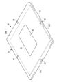
- FIG. FIG. 3 is a perspective view of the electronic cassette viewed from the front side where radiation is incident
- FIG. 3 is a perspective view of the electronic cassette as seen from the rear side
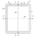
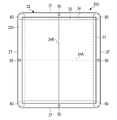
- 2 is a plan view of the electronic cassette as seen from the front side
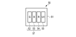
- FIG. It is a schematic diagram which shows an example of a structure of a light emission part.
- FIG. 2 is a front view showing an example of the configuration of an upright imaging platform
- FIG. 4 is a cross-sectional view showing an example of the internal configuration of the standing holder
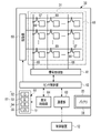
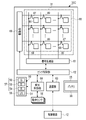
- 2 is a block diagram showing an example of the internal configuration of an electronic cassette;
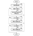
- FIG. 4 is a flowchart showing an example of light emission control by a light emission control unit;
- FIG. 10 is a plan view of an electronic cassette according to a first modified example;
- FIG. 11 is a plan view of an electronic cassette according to a second modified example;
- FIG. 11 is a plan view of an electronic cassette according to a third modified example;
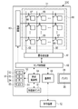
- FIG. 11 is a block diagram showing the internal configuration of an electronic cassette according to a third modified example;
- 2 is a block diagram showing the internal configuration of an electronic cassette incorporating an acceleration sensor;
- FIG. It is a figure explaining normal sterilization mode and rapid sterilization mode.
- FIG. 11 is a schematic diagram showing the configuration of a light emitting unit according to a fifth modified example; It is a figure which shows an example of a structure of a mobile radiation generator.
- FIG. 2 is a diagram showing an example of a configuration of a charging cradle;
- the radiation diagnostic apparatus 10 includes a radiation source 11 , a control device 12 , an upright imaging table 13 and a lying imaging table 14 .
- the radiation source 11 is used both for radiography using the upright imaging table 13 and radiographic imaging using the lying imaging table 14 .
- the upright imaging table 13 and the lying imaging table 14 are examples of the “imaging table” according to the technology of the present disclosure.
- a radiation tube 15 is built into the radiation source 11 .
- the radiation tube 15 generates and emits radiation R.
- Radiation R is, for example, X-rays.
- An irradiation field limiter 16 is attached to the radiation source 11 .
- the radiation source 11 is suspended from the ceiling of the radiography room by a support 18.
- the strut 18 is attached via a carriage to a rail provided on the ceiling.
- the radiation source 11 is horizontally movable in the radiography room by means of rails and carriages.
- the support 18 is extendable in the height direction, and allows the radiation source 11 to be moved in the height direction.
- the radiation source 11 is rotatable about an axis perpendicular to the plane of the drawing.
- the standing-position imaging stand 13 has a stand 20 , a connecting portion 21 , and a standing-position holder 22 .
- the stand 20 is composed of a pedestal 23 installed on the floor of the radiography room and a support 24 extending in the height direction from the pedestal 23 .
- the connecting portion 21 connects the standing position holder 22 to the stand 20 .
- the standing position holder 22 is movable in the height direction, and enables height adjustment according to the part of the patient P to be imaged.
- the standing position holder 22 is box-shaped and accommodates the electronic cassette 30 inside.
- the standing position holder 22 is mostly made of a conductive material having electromagnetic wave shielding properties, such as aluminum or stainless steel. Most of the surface of the standing position holder 22 facing the radiation source 11 is made of a material such as carbon that allows the radiation R to pass therethrough.
- the electronic cassette 30 is an example of a “portable radiation detector” according to the technology of the present disclosure.
- the standing position holder 22 is an example of the “receiving portion” according to the technology of the present disclosure.
- the upright imaging platform 13 is an example of the “accommodation device” according to the technology of the present disclosure.
- the supine position imaging table 14 has a pedestal 40, a connecting part 41, a top plate 42, and a supine position holder 43, which are installed on the floor surface of the radiography room.
- the connecting portion 41 connects the top plate 42 to the base 40 .
- the pedestal 40 is of a lifting type and enables the height of the top plate 42 to be adjusted.
- the top plate 42 has a length and width that allow the patient P to lie on his or her back.
- the top plate 42 is made of a material that transmits radiation R, such as carbon.
- the lying position holder 43 is arranged in a space 41A between the pedestal 40 formed by the connecting portion 41 and the top plate 42 .
- the supine position holder 43 has a box shape whose top is covered with a top plate 42 and accommodates the electronic cassette 30 therein.
- the supine position holder 43 is made of a conductive material having electromagnetic shielding properties, such as aluminum or stainless steel.
- the supine position holder 43 is slidable in the direction along the long side of the top plate 42 by a slide mechanism (not shown).
- the supine position holder 43 is an example of the “accommodating portion” according to the technology of the present disclosure.
- the supine-position imaging table 14 is an example of the “accommodation device” according to the technology of the present disclosure.
- the control device 12 is, for example, a console installed in the control room next to the radiography room.
- a photographing menu is input to the control device 12 by the operator.
- the control device 12 controls radiation imaging by the radiation source 11 and the electronic cassette 30 based on irradiation conditions according to the input imaging menu.
- the control device 12 also receives radiographic images transmitted from the electronic cassette 30 and displays the received radiographic images on a display (not shown).
- the control device 12 communicates with the electronic cassette 30 wirelessly or by wire.
- the control device 12 is communicably connected to a radiology information system (RIS) via a network such as a LAN (Local Area Network).
- RIS radiology information system
- the controller 12 receives the imaging order from the RIS.
- the imaging order includes patient information of the patient P and an imaging menu.
- the control device 12 is also communicably connected to an image database server (not shown) via a network.
- the image database server is, for example, a PACS (Picture Archiving and Communication System) server, receives radiation images from the control device 12, and stores and manages the received radiation images.
- FIG. 2 to 4 show an example of the external configuration of the electronic cassette 30.
- FIG. FIG. 2 is a perspective view of the electronic cassette 30 viewed from the front side where the radiation R is incident.
- FIG. 3 is a perspective view of the electronic cassette 30 as seen from the rear side.
- FIG. 4 is a plan view of the electronic cassette 30 viewed from the front side.
- the electronic cassette 30 has a detection panel 31 that detects radiation R and generates a radiation image, and a housing 32 that houses the detection panel 31 .
- the housing 32 has a flat rectangular parallelepiped shape.
- the housing 32 is composed of a front surface 32A on which radiation R is incident, a rear surface 32B facing the front surface 32A, and four side surfaces 32C.
- the front surface 32A and rear surface 32B are substantially rectangular in plan view.
- a surface composed of the front surface 32A, the rear surface 32B, and the four side surfaces 32C is hereinafter referred to as the outer surface of the housing 32. As shown in FIG.
- the housing 32 is made of, for example, conductive resin.
- the housing 32 has a size conforming to the international standard ISO (International Organization for Standardization) 4090:2001, for example, like a film cassette, an IP (Imaging Plate) cassette, and a CR (Computed Radiography) cassette.
- ISO International Organization for Standardization
- a rectangular opening 33 is formed in the front surface 32A of the housing 32.
- a transmission plate 34 that transmits the radiation R is attached to the opening 33 .
- the transmission plate 34 has a rectangular shape in plan view and is larger than the detection panel 31 .
- the transmission plate 34 is made of, for example, a carbon material that is lightweight, highly rigid, and highly transparent to radiation.
- Lines 34A and 34B indicating the center of the detection panel 31 are formed on the transmission plate 34 by a method such as printing. Lines 34A and 34B are orthogonal to each other, and the intersection of the two corresponds to the center of the imaging area.
- the imaging region is a region of the front surface 32A on which the radiation R that contributes to the generation of the radiographic image by the detection panel 31 is incident.
- a resin protective film (not shown) through which the radiation R is transmitted is attached to the surface of the transmission plate 34 .
- the protective film protects the transmission plate 34 and flattens the surface of the transmission plate 34 .
- the electronic cassette 30 is housed in the standing position holder 22 or the lying position holder 43 so that the radiation source 11 and the front surface 32A are held facing each other. Also, the electronic cassette 30 can be used without being housed in a holder. In this case, the electronic cassette 30 is used, for example, placed between the patient lying on the bed and the bed.
- a battery mounting portion 35 is provided in the central portion of the rear surface 32B of the housing 32 .
- a battery 36 for supplying electric power to the electronic cassette 30 is detachably attached to the battery attachment portion 35 .
- FIG. 3 shows a state in which the battery 36 is attached to the battery attachment portion 35 .
- the battery 36 is a secondary battery such as a rechargeable lithium ion battery.
- a light-emitting section 50 for indicating the operating state of the electronic cassette 30 is provided on the outer surface of the housing 32 .
- the housing 32 has four sides 37 in plan view. Side 37 corresponds to side 32C described above.
- the light emitting section 50 is arranged in the center of each side 37 . That is, the light-emitting portion 50 is formed at a position where the side 37 and an extension line obtained by virtually extending the lines 34A and 34B and the side 37 intersect.
- the light emitting unit 50 is arranged outside the transmission plate 34 . That is, the light emitting unit 50 is arranged outside the area corresponding to the detection panel 31 (that is, the imaging area) on the outer surface of the housing 32 .
- the light-emitting portion 50 is formed to extend from the side surface 32C to the front surface 32A and the rear surface 32B. As a result, the light emitted by the light emitting section 50 spreads to include directions perpendicular to the side surface 32C, the front surface 32A, and the rear surface 32B, and is emitted radially.
- the light emitting unit 50 is an LED module configured by mounting a plurality of LEDs (Light Emitting Diodes) 52 to 55 on a substrate 51, for example.
- the LED module is provided inside the housing 32 and emits light through a translucent plate provided on the outer surface of the housing 32 .
- the LED 52 is a green LED that emits green light.
- the LED 53 is a blue LED that emits blue light.
- the LED 54 is a red LED that emits red light.
- the LED 55 is an ultraviolet LED that emits ultraviolet rays. The LED 55 emits at least part of the ultraviolet rays toward the area corresponding to the detection panel 31 on the outer surface of the housing 32 .
- the LEDs 52-55 function as an indicator 57 that indicates the operational status of the electronic cassette 30 to the operator.
- Operational states include a power-on state, a ready state, and an error state.
- the power-on state is a state in which the electronic cassette 30 is powered on.
- the ready state is a state in which preparations for detection of radiation R by the detection panel 31 have been completed.
- An error state is a state in which an abnormality has occurred in the operation of the electronic cassette 30 . For example, when the power is on, the green LED 52 emits light. In the ready state, the blue LED 53 emits light. In an error condition, the red LED 54 will illuminate.
- the ultraviolet LED 55 is an example of an ultraviolet light source that emits ultraviolet light for sterilization. That is, in this embodiment, the ultraviolet light source is integrated with the indicator 57 .
- sterilization means inactivating bacteria, microorganisms, or viruses adhering to an object to be irradiated with light energy.
- the irradiation time of ultraviolet rays required for sterilization varies depending on the irradiation energy of ultraviolet rays, the distance from the ultraviolet light source to the object to be irradiated, and the type of bacteria or viruses to be sterilized, but is about several minutes to several tens of minutes. For example, it has been reported that the new coronavirus is inactivated by UV irradiation for several minutes.
- the ultraviolet rays emitted by the ultraviolet LEDs 55 are, for example, deep ultraviolet rays having a central wavelength in the range of 200 nm or more and 280 nm or less.
- the UV LED 55 emits deep UV light with a central wavelength of 222 nm. Deep ultraviolet rays with a center wavelength of 222 nm are known to have little effect on the human body (see, for example, Japanese Patent No. 6306097). Therefore, even if the patient P or the like is irradiated with the ultraviolet rays emitted from the ultraviolet LED 55, safety is maintained.
- the ultraviolet LED 55 emits ultraviolet light during a period in which the detection panel 31 does not detect the radiation R (that is, a non-imaging period). For example, the ultraviolet LED 55 emits light for a predetermined irradiation time when the power is on.
- FIG. 6 shows an example of the configuration of the standing imaging stand 13.
- a tray 25 is slidably attached to the standing position holder 22 .
- rails 26 Inside the standing position holder 22 are provided rails 26 (see FIG. 7) for guiding the movement of the tray 25, a position fixing frame 27 for determining the mounting position of the electronic cassette 30 with respect to the tray 25, and a lock for locking the tray 25 in the inserted state.
- a mechanism (not shown) is provided.
- FIG. 6 shows a state in which the locking mechanism is unlocked and the tray 25 is pulled out from the standing position holder 22 .
- An electronic cassette 30 is detachably set on the tray 25 .
- the tray 25 is provided with a holding mechanism that vertically sandwiches and holds the electronic cassette 30 .
- the surface 22A of the standing position holder 22 has a radiation transmitting region 28 formed of a material that transmits the radiation R, such as carbon.
- FIG. 7 schematically shows a cross section of the holder 22 for standing position.
- the inner surface of the standing position holder 22 is formed with an ultraviolet reflecting portion 29 that reflects the ultraviolet rays UV emitted from the LED 55 (see FIG. 5) included in the light emitting portion 50 of the standing position holder 22. It is The ultraviolet reflector 29 faces at least the radiation detection surface of the electronic cassette 30 .
- a radiation detection surface is a region corresponding to the detection panel 31 on the outer surface of the housing 32 .
- the ultraviolet reflecting part 29 is a reflecting film that mirror-reflects or diffusely reflects deep ultraviolet rays.
- the ultraviolet reflecting portion 29 is formed, for example, by coating the inner surface of the standing position holder 22 with paint having ultraviolet reflecting properties by screen printing or the like.
- paint having UV reflectivity for example, "Hi-UVC", a highly reflective UV ink manufactured by Okamoto Glass Co., Ltd. pdf) can be used.
- the ultraviolet reflecting portion 29 is formed by bonding a laminated substrate formed by depositing an ultraviolet reflecting material on a metal substrate such as aluminum to the inner surface of the standing position holder 22 via an adhesive layer.
- a UVC reflector "MIRO-UV-C” https://www.materialhouse.co.jp/miro-top/newmirouv/) manufactured by Material House Co., Ltd. can be used.
- the ultraviolet reflecting portion 29 may be formed of a metal member. In this case, for example, an aluminum material with a protective film on the surface, a metal body such as SUS (Stainless Used Steel) material, a composite material formed by vapor-depositing metal on a resin film (Alpet (registered trademark), etc. It can be used as the ultraviolet reflecting portion 29 .
- the ultraviolet rays UV emitted from the light emitting section 50 are reflected by the ultraviolet reflecting section 29 and enter the housing 32 of the electronic cassette 30 .
- the entire exposed portion of the outer surface of the housing 32 is irradiated with the ultraviolet rays UV.
- the electronic cassette 30 is sterilized.
- the inside of the standing position holder 22, the tray 25, and the like are also sterilized by being irradiated with ultraviolet rays UV.
- FIG. 7 schematically shows part of the ultraviolet rays UV emitted from the light emitting section 50.
- the supine holder 43 has the same configuration as the standing holder 22, so the description thereof is omitted.
- FIG. 8 shows an example of the internal configuration of the electronic cassette 30.
- the electronic cassette 30 has a detection panel 31 , a drive section 60 , a signal processing section 61 , a sensor control section 62 , a communication section 63 , a light emission control section 64 and a light emission section 50 .
- the electronic cassette 30 of this embodiment is an indirect conversion type radiation detector that converts radiation into light (visible light) and then converts the converted light into charges.
- the sensor control unit 62 and the light emission control unit 64 are each configured by a processor such as an IC (Integrated Circuit). Note that the sensor control unit 62 and the light emission control unit 64 may be configured by one processor. Moreover, the sensor control unit 62 and the light emission control unit 64 may be configured by a processor that executes processing based on a program stored in memory.
- a processor such as an IC (Integrated Circuit).
- a scintillator 65 as a conversion layer is laminated on the detection panel 31 .
- the scintillator 65 is made of, for example, GOS (Gd 2 O 2 :Tb) or CsI (CsI:TI).
- the scintillator 65 converts the radiation R emitted from the radiation source 11 (see FIG. 1) and transmitted through the imaging region of the patient P into visible light.
- Photodiodes 66 as photoelectric conversion elements are arranged in a two-dimensional matrix on the detection panel 31 .
- the photodiode 66 generates charges in response to the light converted by the scintillator 65 and accumulates the generated charges.
- the photodiode 66 is connected to a signal line 68 via a TFT (Thin Film Transistor) 67 as a switching element.
- a gate of the TFT 67 is connected to the scanning line 69 .
- the driving section 60 is, for example, a gate driver, and is connected to a plurality of scanning lines 69 .
- the drive section 60 applies voltage to the scanning line 69 based on the timing signal supplied from the sensor control section 62 .
- the TFT 67 When a voltage is applied through the scanning line 69 , the TFT 67 is turned on and outputs an electric signal corresponding to the charge accumulated in the photodiode 66 to the signal line 68 .
- the electrical signal output to the signal line 68 is input to the signal processing section 61 .
- the signal processing unit 61 generates image data according to the electrical signals input from each of the signal lines 68, and outputs it to the outside via the communication unit 63 as a radiographic image.
- the signal processing unit 61 is a signal processing circuit including an amplifier circuit, a correlated double sampling circuit, a multiplexer, an A/D converter, and the like.
- the communication unit 63 communicates with the control device 12, for example, wirelessly.
- the communication unit 63 receives control signals transmitted from the control device 12 and inputs them to the sensor control unit 62 , transmits radiographic images generated by the sensor control unit 62 to the control device 12 , and the like.
- the light emission control section 64 controls the light emission operation of the light emission section 50 .
- the sensor control unit 62 turns on any one of the LEDs 52 to 55 included in the light emitting unit 50 or Light multiple lights.
- the electronic cassette 30 is of the indirect conversion type in this embodiment, it may be of the direct conversion type.
- a direct conversion radiation detector uses a conversion layer such as amorphous selenium (a-Se) that converts the radiation R directly into electrical charges.
- a-Se amorphous selenium
- a capacitor is provided for accumulating charges generated by the conversion layer.
- FIG. 9 is a flowchart showing an example of light emission control by the light emission control unit 64.
- the light emission control unit 64 determines the operating state of the electronic cassette 30 that is being executed based on the control of the sensor control unit 62 (step S10).
- the light emission control unit 64 determines whether or not the operating state is the power-on state (step S11).
- step S11 the power-on state
- step S12 the green LED 52 and the ultraviolet LED 55 are caused to emit light
- the light emission control unit 64 returns the process to step S10.
- step S11 determines whether the operating state is the power-on state (step S11: NO).
- step S13 determines whether the operating state is the ready state (step S13).
- step S13 determines that the operating state is the ready state (step S13: YES)
- step S14 the blue LED 53 emits light (step S14). After step S14, the light emission control unit 64 returns the process to step S10.
- step S13 determines whether the operating state is an error state (step S15).
- step S15 determines that the operating state is the error state (step S15: YES)
- step S16 the red LED 54 emits light (step S16). After step S16, the light emission control unit 64 returns the process to step S10.
- step S15: NO the process ends.
- the ultraviolet LED 55 as an ultraviolet light source that emits ultraviolet light for sterilization emits light when the power is on. That is, the light emission of the ultraviolet LED 55 is stopped in the ready state and the error state.
- the ready state corresponds to the operator inputting an imaging menu to the control device 12 or the control device 12 receiving an imaging order from the RIS.
- the patient P is placed in the vicinity of the electronic cassette 30 and preparations for radiation imaging are performed. Therefore, by prohibiting the emission of the ultraviolet LED 55 in the ready state, the patient P and the like are irradiated with ultraviolet rays. can be suppressed.
- the light-emitting portion 50 containing the ultraviolet LED 55 as an ultraviolet light source on the outer surface of the electronic cassette 30, sterilization using ultraviolet rays can be performed efficiently.
- the cost since it is not necessary to separately use a device having an ultraviolet light source to sterilize the electronic cassette 30, the cost can be reduced.
- the light emission control unit 64 causes the ultraviolet LED 55 to emit light when the power of the electronic cassette 30 is on. good.
- the light emission control unit 64 causes the ultraviolet LED 55 to emit light according to the operating state of the electronic cassette 30.
- the operator causes the ultraviolet LED 55 to emit light based on the operation signal input to the control device 12.
- the electronic cassette 30 may be provided with an operation unit such as an operation switch for causing the ultraviolet LED 55 to emit light by an operator's operation.
- the light emission control section 64 may cause the ultraviolet LED 55 to emit light in response to turning on a power switch (not shown) provided in the electronic cassette 30 .
- FIG. 10 shows an electronic cassette 30A according to a first modified example.
- one light emitting unit 50 is arranged on each side 37 of the housing 32 .
- a plurality of light emitting units 50 are arranged along each side 37 of the housing 32 .
- the light-emitting portions 50 other than the light-emitting portion 50 located in the center of each side 37 may include only the ultraviolet LED 55 among the LEDs 52-55. That is, a plurality of ultraviolet light sources alone may be arranged on each side 37 .
- an ultraviolet lamp such as an excimer lamp may be used instead of the ultraviolet LED 55 . Since the ultraviolet lamps are bar-shaped, they can be arranged along each side 37 of the housing 32 .
- FIG. 11 shows an electronic cassette 30B according to a second modification.
- the electronic cassette 30B according to the second modified example has a light storage section 70 that absorbs ultraviolet rays and emits visible light on the outer surface of the housing 32 .
- the light storing section 70 is arranged outside the transmission plate 34 . That is, the light storing section 70 is arranged outside the area corresponding to the detection panel 31 (that is, the imaging area) on the outer surface of the housing 32 .
- the luminous units 70 are provided at the four corners of the front surface 32A of the housing 32 .
- the luminous portion 70 is formed, for example, by applying a luminous paint to the outer surface of the housing 32 by screen printing or the like.
- a luminous paint As for paints with luminous properties, luminous paints manufactured by Asahipen Co., Ltd. (https://www.asahipen.jp/products/view/16813), transparent luminous paints manufactured by Tateyama Kagaku Kogyo Co., Ltd. (https:/ /www.tateyama.jp/product/dev_newmaterial.html) etc. can be adopted.
- the light storing section 70 While the outer surface of the housing 32 is irradiated with the ultraviolet rays emitted from the ultraviolet LEDs 55, the light storing section 70 absorbs the emitted ultraviolet rays and emits visible light. The light storing section 70 emits visible light even after the ultraviolet LED 55 stops emitting light. The amount of visible light emitted from the light storage unit 70 gradually decreases after the ultraviolet irradiation is stopped, and is extinguished after a certain period of time.
- the operator can easily visually confirm whether or not the electronic cassette 30B has been sterilized.
- the luminous portion 70 can be formed by applying a luminous material instead of applying the luminous material.
- the luminous portion 70 can be formed by attaching a film-like luminous material to the outer surface of the housing 32 .
- This film-like phosphorescent material is preferably peelable.
- the luminous section 70 is provided on the front surface 32A of the housing 32, but may be provided on the rear surface 32B of the housing 32, or may be provided on both the front surface 32A and the rear surface 32B. may have been
- FIG. 12 shows an electronic cassette 30C according to a third modified example.
- an electronic cassette 30C according to the third modification has a moving body sensor 80 that detects a moving body.
- the moving body sensors 80 are built in the four corners of the housing 32 .
- the moving body sensor 80 detects a change in infrared rays, a change in reflected ultrasonic waves, a change in visible light, or the like through a window (not shown) provided on the outer surface of the housing 32, thereby detecting the movement of the electronic cassette 30C. Detect the presence of people in the surroundings.
- the moving body sensor 80 is an example of a “human sensor” according to the technology of the present disclosure.
- the moving body sensor 80 is connected to the light emission control section 64.
- the light emission control unit 64 performs light emission prohibition control for prohibiting emission of ultraviolet rays from the ultraviolet LEDs 55 when at least one of the plurality of moving body sensors 80 detects a moving body. For example, in addition to the light emission control shown in FIG.
- the number of moving object sensors 80 is not limited, and only one moving object sensor 80 may be provided in the electronic cassette 30C.
- an acceleration sensor 81 for detecting acceleration may be provided.
- the acceleration sensor 81 is connected to the light emission control section 64 .
- the light emission control unit 64 executes light emission prohibition control for prohibiting the ultraviolet LED 55 from emitting ultraviolet rays when the acceleration sensor 81 detects an acceleration equal to or greater than a predetermined value.
- the light emission control unit 64 performs light emission prohibition control based on the detection signal of the acceleration sensor 81 in addition to the light emission control shown in FIG.
- the electronic cassette 30C is subjected to acceleration of a certain value or more.
- the acceleration sensor 81 indirectly detects the presence of a person by acceleration, and thus can be used as a human sensor.
- a voice sensor that detects noise such as voice as the human sensor.
- the light emission control unit 64 controls the irradiation time and intensity of the ultraviolet rays emitted by the ultraviolet LEDs 55, thereby providing a normal sterilization mode in which the irradiation time is relatively long and a rapid sterilization mode in which the irradiation time is relatively short. be executable.
- the light emission control unit 64 sets the intensity of the ultraviolet rays below a predetermined value in the normal sterilization mode, and sets the intensity of the ultraviolet rays to a predetermined value or more in the rapid sterilization mode.
- the light emission control unit 64 sets the irradiation time to T1 and the intensity to I1 in the normal sterilization mode. In addition, the light emission control unit 64 sets the irradiation time to T2 and the intensity to I2 in the rapid sterilization mode.
- the irradiation time satisfies the relationship of T1>T2, and the intensity satisfies the relationship of I1 ⁇ I2.
- the light emission control unit 64 changes the intensity of the ultraviolet rays by controlling the driving current of the ultraviolet LEDs 55, for example.
- the light emission control unit 64 controls the pulse width of the drive pulse (that is, controls the duty ratio) to change the effective voltage or effective current. may change the intensity of the UV light.
- the light emission control unit 64 switches between the normal sterilization mode and the rapid sterilization mode, for example, based on an operation signal input to the control device 12 by an operator.
- the normal sterilization mode since the intensity of ultraviolet rays is low, deterioration of the timing of the housing 32 of the electronic cassette 30 due to ultraviolet irradiation is alleviated.
- the normal sterilization mode since the intensity of ultraviolet rays is low and the effect on the human body is small, the normal sterilization mode is suitable when the electronic cassette 30C is used without being housed in a holder (standing holder 22 or lying holder 43). .
- the rapid sterilization mode is used, for example, when sterilization of the electronic cassette 30C is urgently required. Further, when the rapid sterilization mode is selected, the light emission control unit 64 preferably switches from the rapid sterilization mode to the normal sterilization mode when the human sensor detects the presence of a person.
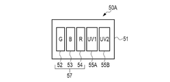
- FIG. 16 shows a light emitting section 50A according to a fifth modification.
- a light emitting section 50A shown in FIG. 16 is used instead of the light emitting section 50 shown in FIG.
- the light-emitting portion 50A has, in addition to the LEDs 52 to 54 as the indicator 57, a first ultraviolet LED 55A and a second ultraviolet LED 55B.
- the first ultraviolet LED 55A and the second ultraviolet LED 55B generate different wavelengths of ultraviolet rays.
- the first ultraviolet LED 55A is an example of the "first ultraviolet light source” according to the technology of the present disclosure.
- the second ultraviolet LED 55B is an example of a "second ultraviolet light source” according to the technology of the present disclosure.
- the first ultraviolet LED 55A emits first ultraviolet light having a first center wavelength.
- the first center wavelength is, for example, 222 nm.
- the second ultraviolet LED 55B emits second ultraviolet light having a second center wavelength longer than the first center wavelength.
- the second center wavelength is, for example, 254 nm. It is known that the second ultraviolet rays with a central wavelength of 254 nm have a greater effect on the human body than the ultraviolet rays with a central wavelength of 222 nm, but have a high sterilizing effect.
- the light emission control unit 64 causes the first ultraviolet LED 55A to emit light in the normal sterilization mode described in the fourth modified example, and causes the second ultraviolet LED 55B to emit light in the rapid sterilization mode. As a result, sterilization can be performed more efficiently in the rapid sterilization mode.
- the first center wavelength may be 207 nm. It is known that ultraviolet rays with a central wavelength of 207 nm also have little effect on the human body, like ultraviolet rays with a central wavelength of 222 nm.
- the electronic cassette 30 is accommodated in the standing holder 22 of the standing imaging table 13 or the lying holder 43 of the lying imaging table 14 provided in the radiation diagnostic apparatus 10 (see FIG. 1). Used for shooting.
- the electronic cassette 30 can be used not only with the radiation diagnostic apparatus 10 but also with a mobile radiation generator.
- FIG. 17 shows an example of a mobile radiation generator.
- a mobile radiation generator 90 shown in FIG. Four wheels 94 are attached to the lower portion of the body portion 91 in the front, rear, left, and right directions.
- the mobile radiation generator 90 can be moved within the medical facility by means of the wheels 94, and is used for so-called round radiography, in which the radiography of a patient is performed while going around the hospital room. For this reason, the mobile radiation generator 90 is also called a medical cart. Also, the mobile radiation generator 90 can be brought into the operating room to take radiographs during surgery.
- the body portion 91 includes a central portion 95 and a housing portion 96 .
- a control device 97 is housed in the central portion 95 .
- the housing portion 96 is a holder for housing the electronic cassette 30 when not in use.
- the mobile radiation generator 90 is an example of the “accommodation device” according to the technology of the present disclosure.
- the housing portion 96 is arranged on the back surface of the central portion 95 .
- the housing portion 96 has a housing portion main body 100 and a lid 101 .
- the lid 101 can be opened and closed with respect to the container main body 100 .
- a plurality of electronic cassettes 30 can be accommodated in the accommodation unit main body 100 .
- a handle 107 that is gripped by the operator is provided at a position protruding upward from the central portion 95 .
- An irradiation switch 108 is attached to the upper back surface of the central portion 95 .
- the irradiation switch 108 is a switch for the operator to instruct the start of radiation R irradiation.
- the irradiation switch 108 is connected to an extension cable (not shown) and can be removed from the central portion 95 for use.
- the strut part 92 is erected above the front wheel 94 .
- the arm portion 93 is attached to the support portion 92 at its proximal end.
- a radiation source 110 is attached to the arm portion 93 on the side opposite to the proximal end.
- a radiation tube 111 is built in the radiation source 110 .
- An irradiation field limiter 112 is also attached to the radiation source 110 .
- An ultraviolet reflecting portion 120 is formed on the inner surface of the accommodating portion 96 in the same manner as in the above embodiment.
- the ultraviolet reflecting part 120 is a reflecting film that mirror-reflects or diffusely reflects deep ultraviolet rays.
- the configuration of the ultraviolet reflecting portion 120 is the same as the configuration of the above-described ultraviolet reflecting portion 29 (see FIG. 7).
- the ultraviolet rays UV are repeatedly reflected inside the accommodating portion 96, thereby causing the portion of the outer surface of the housing 32 exposed to the outside. Ultraviolet rays are applied to the entire surface. Thereby, the electronic cassette 30 is sterilized.
- FIG. 18 shows an example charging cradle.
- a charging cradle 200 shown in FIG. 18 includes a housing portion 210 and a charging control portion 220 .
- Charging cradle 200 is an example of the “accommodating device” according to the technology of the present disclosure.
- the housing portion 210 has the same configuration as the housing portion 96 in the sixth modified example, and has a housing portion main body 211 and a lid 212 .
- the lid 212 can be opened and closed with respect to the housing body 211 .
- a plurality of electronic cassettes 30 can be accommodated in the accommodation unit main body 211 .
- the charging control section 220 is connected to the electronic cassette 30 housed in the housing section 210 and charges the battery 36 of the electronic cassette 30 . Electric power is supplied from an external power supply to the charging control unit 220 via a power cable 221 .
- An ultraviolet reflecting portion 230 is formed on the inner surface of the accommodating portion 210 in the same manner as in the above embodiment.
- the ultraviolet reflecting portion 230 is a reflecting film that mirror-reflects or diffusely reflects deep ultraviolet rays.
- the configuration of the ultraviolet reflecting portion 230 is the same as the configuration of the above-described ultraviolet reflecting portion 29 (see FIG. 7).
- the ultraviolet rays UV are repeatedly reflected inside the accommodating portion 210, resulting in a portion of the outer surface of the housing 32 exposed to the outside. Ultraviolet rays are applied to the entire surface. Thereby, the electronic cassette 30 is sterilized.
- a and/or B is synonymous with “at least one of A and B.” That is, “A and/or B” means that only A, only B, or a combination of A and B may be used. Also, in this specification, when three or more matters are expressed by connecting with “and/or”, the same idea as “A and/or B" is applied.
Landscapes
- Health & Medical Sciences (AREA)
- Life Sciences & Earth Sciences (AREA)
- Engineering & Computer Science (AREA)
- Physics & Mathematics (AREA)
- High Energy & Nuclear Physics (AREA)
- Molecular Biology (AREA)
- Medical Informatics (AREA)
- Pathology (AREA)
- Surgery (AREA)
- Spectroscopy & Molecular Physics (AREA)
- Nuclear Medicine, Radiotherapy & Molecular Imaging (AREA)
- Optics & Photonics (AREA)
- General Physics & Mathematics (AREA)
- Radiology & Medical Imaging (AREA)
- Biomedical Technology (AREA)
- Heart & Thoracic Surgery (AREA)
- Biophysics (AREA)
- Animal Behavior & Ethology (AREA)
- General Health & Medical Sciences (AREA)
- Public Health (AREA)
- Veterinary Medicine (AREA)
- Photometry And Measurement Of Optical Pulse Characteristics (AREA)
- Measurement Of Radiation (AREA)
- Apparatus For Radiation Diagnosis (AREA)
Abstract
可搬型放射線検出器は、放射線を検出して放射線画像を生成する検出パネルと、検出パネルを収容する筐体と、筐体の外面に配置され、紫外線を発する紫外線源と、を備える。
Description
本開示の技術は、可搬型放射線検出器及び収容装置に関する。
近年の新型コロナウイルス(正式名称:SARS(Severe Acute Respiratory Syndrome)-Cov(Coronavirus)-2)の流行により、医療機関においてもクラスターと呼ばれる集団感染が発生している。このため、医療機関における各種検査及び診断には細心の感染予防対策が必要とされている。感染予防対策として、紫外線照射による殺菌が有効である。新型コロナウイルスについても、紫外線照射を行うことで不活性化することが報告されている。
放射線診断装置で使用される放射線検出器には、可搬型のものがある。可搬型放射線検出器は、放射線技師等のオペレータ及び患者に直接触れる機会が多く、菌又はウイルス等が付着しやすい。このことから、放射線撮影に用いられる機器に紫外線源を設けることにより、可搬型放射線検出器に紫外線を照射して殺菌を行うことが提案されている。
例えば、特開2009-172243号公報には、可搬型放射線検出器を充電するための充電クレードルの内部に紫外線源を設けることが記載されている。クレードルに装填された可搬型放射線検出器は、紫外線源から紫外線が照射されることにより殺菌される。
また、特開2013-248124号公報には、移動式の放射線発生装置に設けられた可搬型放射線検出器を収納するための収納ホルダ内に殺菌灯(すなわち紫外線源)を設けることが記載されている。収納ホルダに収納された可搬型放射線検出器は、紫外線源から紫外線が照射されることにより殺菌される。
特開2009-172243号公報又は特開2013-248124号公報に記載された装置では、可搬型放射線検出器を殺菌するためには、紫外線源が設けられた充電クレードル又は収納ホルダに収納する必要がある。可搬型放射線検出器を殺菌するために、紫外線源が設けられた装置を用いることは、コストが嵩む。これに代えて、オペレータ等が自ら可搬型放射線検出器を殺菌することは、作業負担が大きい。このようなコスト及び作業負担の低減を図るために、可搬型放射線検出器の殺菌を効率化することが望まれている。
本開示の技術は、紫外線による殺菌を効率よく行うことを可能とする可搬型放射線検出器及び収容装置を提供することを目的とする。
本開示の可搬型放射線検出器は、放射線を検出して放射線画像を生成する検出パネルと、検出パネルを収容する筐体と、筐体の外面に配置され、紫外線を発する紫外線源と、を備える。
紫外線源は、筐体の外面において検出パネルに対応する領域の外側に配置されていることが好ましい。
紫外線源は、少なくとも一部の紫外線を、筐体の外面において検出パネルに対応する領域に向けて発することが好ましい。
筐体は矩形状であり、紫外線源は、筐体の各辺に1つずつ配置されていることが好ましい。
紫外線源は、筐体の各辺の中央に配置されていることが好ましい。
筐体の各辺の中央にインジケータが設けられており、紫外線源は、インジケータと一体化されていることが好ましい。
筐体は矩形状であり、紫外線源は、筐体の各辺に沿って複数配置されていることが好ましい。
筐体の外面に設けられ、紫外線を吸収して可視光を発する蓄光部を備えることが好ましい。
蓄光部は、筐体の外面において検出パネルに対応する領域の外側に、蓄光材を塗布又は貼り付けることにより形成されていることが好ましい。
人の存在を検知する人感センサと、人感センサが人の存在を検知した場合に、紫外線源による紫外線の出射を禁止する発光制御部と、を備えることが好ましい。
人感センサは、動体を検知する動体センサ、又は、加速度を検知する加速度センサであることが好ましい。
紫外線源を制御し、紫外線の照射時間が相対的に長い通常殺菌モードと、紫外線の照射時間が相対的に短い急速殺菌モードとを実行可能とする発光制御部を備えることが好ましい。
発光制御部は、通常殺菌モードでは紫外線の強度を一定値未満とし、急速殺菌モードでは紫外線の強度を一定値以上とすることが好ましい。
紫外線源には、第1中心波長を有する第1紫外線を出射する第1紫外線源と、第1中心波長よりも長波長の第2中心波長を有する第2紫外線を出射する第2紫外線源とを含み、発光制御部は、通常殺菌モードでは第1紫外線源に第1紫外線を出射させ、急速殺菌モードでは第2紫外線を出射させることが好ましい。
第1中心波長は222nmであり、第2中心波長は254nmであることが好ましい。
本開示の収容装置は、上記いずれかの可搬型放射線検出器が収容される収容部と、収容部の内面に形成され、紫外線源から出射された紫外線を反射する紫外線反射部と、を備える。
収容部は、撮影台に設けられたホルダ、移動式の放射線発生装置に設けられたホルダ、又は充電クレードルに設けられたホルダであることが好ましい。
紫外線反射部は、少なくとも可搬型放射線検出器の放射線検出面に対向することが好ましい。
紫外線による殺菌を効率よく行うことを可能とする可搬型放射線検出器及び収容装置を提供することができる。
一例として図1に示すように、放射線診断装置10は、放射線源11、制御装置12、立位撮影台13、及び臥位撮影台14を備える。放射線源11は、立位撮影台13を用いた放射線撮影と、臥位撮影台14を用いた放射線撮影とで兼用される。なお、立位撮影台13及び臥位撮影台14は、本開示の技術に係る「撮影台」の一例である。
放射線源11には放射線管15が内蔵されている。放射線管15は、放射線Rを生成して出射する。放射線Rは、例えばX線である。また、放射線源11には照射野限定器16が取り付けられている。照射野限定器16は、コリメータとも呼ばれ、放射線Rの照射野を規定する。
放射線源11は、支柱18によって放射線撮影室の天井から吊り下げられている。支柱18は、天井に設けられたレールにキャリッジを介して取り付けられている。放射線源11は、レール及びキャリッジによって、放射線撮影室内において水平方向に移動可能である。また、支柱18は、高さ方向に伸縮可能であり、放射線源11を高さ方向に移動可能とする。さらに、放射線源11は、紙面と直交する軸を回転軸として回転可能である。
立位撮影台13は、スタンド20、接続部21、及び立位用ホルダ22を有する。スタンド20は、放射線撮影室の床面に設置される台座23と、台座23から高さ方向に延びる支柱24とで構成されている。接続部21は、立位用ホルダ22をスタンド20に接続する。立位用ホルダ22は、高さ方向に移動可能であり、患者Pの撮影部位に応じた高さ調節を可能とする。
立位用ホルダ22は、箱状であって、内部に電子カセッテ30を収容する。立位用ホルダ22は、大部分がアルミニウム又はステンレス等の電磁波遮蔽性を有する導電性材料によって形成されている。また、立位用ホルダ22は、放射線源11と対向する表面の大部分がカーボン等の放射線Rを透過させる材料によって形成されている。なお、電子カセッテ30は、本開示の技術に係る「可搬型放射線検出器」の一例である。また、立位用ホルダ22は、本開示の技術に係る「収容部」の一例である。さらに、立位撮影台13は、本開示の技術に係る「収容装置」の一例である。
臥位撮影台14は、放射線撮影室の床面に設置される台座40、接続部41、天板42、及び臥位用ホルダ43を有する。接続部41は、天板42を台座40に接続する。台座40は昇降式であり、天板42の高さ調節を可能とする。天板42は、患者Pが仰臥することができる長さ及び幅を有する。天板42は、カーボン等の放射線Rを透過する材料によって形成されている。
臥位用ホルダ43は、接続部41によって形成された台座40と天板42との間の空間41Aに配されている。臥位用ホルダ43は、天板42によって上部が覆われた箱状であり、内部に電子カセッテ30を収容する。臥位用ホルダ43は、アルミニウム又はステンレス等の電磁波遮蔽性を有する導電性材料によって形成されている。臥位用ホルダ43は、スライド機構(図示せず)によって、天板42の長辺方向に沿う方向にスライド移動可能である。なお、臥位用ホルダ43は、本開示の技術に係る「収容部」の一例である。また、臥位撮影台14は、本開示の技術に係る「収容装置」の一例である。
制御装置12は、例えば放射線撮影室の隣室の制御室に設置されるコンソールである。制御装置12には、オペレータにより撮影メニューが入力される。制御装置12は、入力された撮影メニューに応じた照射条件に基づいて、放射線源11及び電子カセッテ30による放射線撮影に係る制御を行う。また、制御装置12は、電子カセッテ30から送信される放射線画像を受信し、受信した放射線画像をディスプレイ(図示せず)に表示させる。制御装置12は、無線又は有線で電子カセッテ30と通信する。
制御装置12は、LAN(Local Area Network)等のネットワークを介して、放射線科情報システム(RIS:RadiologyInformation System)と通信可能に接続されている。制御装置12は、RISから撮影オーダーを受信する。撮影オーダーには、患者Pの患者情報と撮影メニューとが含まれる。また、制御装置12は、ネットワークを介して、画像データベースサーバ(図示せず)と通信可能に接続されている。画像データベースサーバは、例えば、PACS(Picture Archiving and Communication System)サーバであり、制御装置12から放射線画像を受信し、受信した放射線画像を蓄積管理する。
図2から図4は、電子カセッテ30の外観構成の一例を示す。図2は、電子カセッテ30を、放射線Rが入射する前面側から見た斜視図である。図3は、電子カセッテ30を、背面側から見た斜視図である。図4は、電子カセッテ30を、前面側から見た平面図である。
電子カセッテ30は、放射線Rを検出して放射線画像を生成する検出パネル31と、検出パネル31を収容する筐体32とを有する。筐体32は、扁平した直方体形状である。筐体32は、放射線Rが入射する前面32A、前面32Aと対向する背面32B、及び4つの側面32Cで構成されている。前面32A及び背面32Bは、平面視において、ほぼ矩形状である。以下、前面32A、背面32B、及び4つの側面32Cで構成される面を、筐体32の外面という。
筐体32は、例えば導電性樹脂で形成されている。筐体32は、例えば、フイルムカセッテやIP(Imaging Plate)カセッテ、CR(Computed Radiography)カセッテと同様、国際規格ISO(International Organization for Standardization)4090:2001に準拠した大きさである。
筐体32の前面32Aには、矩形状の開口33が形成されている。開口33には、放射線Rを透過させる透過板34が取り付けられている。透過板34は、平面視において矩形状であって、検出パネル31よりも大きい。透過板34は、例えば、軽量で剛性が高く、かつ放射線透過性が高いカーボン材料で形成されている。透過板34には、検出パネル31の中心を示すライン34A,34Bが、印刷等の方法により形成されている。ライン34Aとライン34Bとは互いに直交しており、両者の交点が撮像領域の中心に対応する。撮像領域とは、前面32Aのうち、検出パネル31による放射線画像の生成に寄与する放射線Rが入射する領域である。
また、透過板34の表面には、放射線Rが透過する樹脂製の保護フィルム(図示せず)が貼り付けられている。保護フィルムは、透過板34を保護するとともに、透過板34の表面を平坦化する。
電子カセッテ30は、放射線源11と前面32Aが対向する姿勢で保持されるように、立位用ホルダ22又は臥位用ホルダ43に収容される。また、電子カセッテ30は、ホルダに収容せずに使用することも可能である。この場合、電子カセッテ30は、例えば、ベッド上に仰臥した患者とベッドとの間に配置して使用される。
筐体32の背面32Bの中央部分には、バッテリ装着部35が設けられている。バッテリ装着部35には、電子カセッテ30に電力を供給するためのバッテリ36が着脱自在に装着される。図3は、バッテリ36がバッテリ装着部35に装着された状態を示している。バッテリ36は、充電が可能なリチウムイオン電池等の二次電池である。
筐体32の外面には、電子カセッテ30の動作状態等を示すための発光部50が設けられている。図4に示すように、平面視において、筐体32は、4つの辺37を有する。辺37は、上述の側面32Cに対応する。発光部50は、各辺37の中央に配置されている。すなわち、発光部50は、辺37と、ライン34A,34Bを仮想的に延長した延長線と、辺37とが交わる位置に形成されている。また、発光部50は、透過板34の外側に配置されている。すなわち、発光部50は、筐体32の外面において検出パネル31に対応する領域(すなわち撮像領域)の外側に配置されている。
また、発光部50は、図2及び図3に示すように、側面32Cから前面32A及び背面32Bに延伸するように形成されている。これにより、発光部50が発した光は、側面32C、前面32A、及び背面32Bにそれぞれ直交する方向を含むように広がって放射状に出射される。
図5は、発光部50の構成の一例を示す。図5に示すように、発光部50は、例えば、基板51に複数のLED(Light Emitting Diode)52~55を実装することにより構成されたLEDモジュールである。LEDモジュールは、筐体32の内部に設けられており、筐体32の外面に設けられた透光板を介して光を出射する。
LED52は、緑色の光を発する緑色LEDである。LED53は、青色の光を発する青色LEDである。LED54は、赤色の光を発する赤色LEDである。LED55は、紫外線を発する紫外線LEDである。LED55は、少なくとも一部の紫外線を、筐体32の外面において検出パネル31に対応する領域に向けて発する。
LED52~55は、電子カセッテ30の動作状態をオペレータに対して示すインジケータ57として機能する。動作状態には、電源オン状態、レディー状態、及びエラー状態が含まれる。電源オン状態は、電子カセッテ30の電源がオンとなった状態である。レディー状態は、検出パネル31による放射線Rの検出準備が完了した状態である。エラー状態は、電子カセッテ30の動作に異常が発生した状態である。例えば、電源オン状態では、緑色LED52が発光する。レディー状態では、青色LED53が発光する。エラー状態では、赤色LED54が発光する。
紫外線LED55は、殺菌用の紫外線を発する紫外線源の一例である。すなわち、本実施形態では、紫外線源は、インジケータ57と一体化されている。本開示において、殺菌とは、照射対象物に付着した細菌、微生物類、又はウイルスを、光エネルギーにより不活性な状態にすることを意味する。殺菌に必要な紫外線の照射時間は、紫外線の照射エネルギー、紫外線源から照射対象物までの距離、及び殺菌対象の細菌又はウイルスの種類等により異なるが、数分~数十分程度である。例えば、新型コロナウイルスは、数分間の紫外線の照射により不活性化するとの報告がある。
紫外線LED55が発する紫外線は、例えば、200nm以上かつ280nm以下の範囲に中心波長を有する深紫外線である。本実施形態では、紫外線LED55は、222nmに中心波長を有する深紫外線を発する。中心波長222nmの深紫外線は、人体への影響が小さいことが知られている(例えば、特許第6306097号参照)。このため、紫外線LED55から出射された紫外線が患者P等に照射されたとしても安全性が保たれる。紫外線LED55は、検出パネル31による放射線Rの検出動作が行われていない期間(すなわち非撮影期間)に紫外線を出射する。例えば、紫外線LED55は、電源オン状態において、所定の照射時間だけ発光する。
図6は、立位撮影台13の構成の一例を示す。図6に示すように、立位用ホルダ22には、トレイ25がスライド可能に取り付けられている。立位用ホルダ22内には、トレイ25の移動をガイドするレール26(図7参照)、トレイ25に対する電子カセッテ30の取り付け位置を決める位置固定枠27、及びトレイ25を挿入状態でロックするロック機構(図示せず)が設けられている。図6は、ロック機構のロックが解除されて、トレイ25が立位用ホルダ22から引き出された状態を示している。
トレイ25には、電子カセッテ30が着脱可能にセットされる。トレイ25には、電子カセッテ30を上下方向で挟み込んで保持する保持機構が設けられている。
また、立位用ホルダ22の表面22Aは、カーボン等の放射線Rを透過させる材料によって形成された放射線透過領域28を有する。
図7は、立位用ホルダ22の断面を概略的に示す。図7に示すように、立位用ホルダ22の内面には、立位用ホルダ22の発光部50に含まれるLED55(図5参照)から出射された紫外線UVを反射する紫外線反射部29が形成されている。紫外線反射部29は、少なくとも電子カセッテ30の放射線検出面に対向する。放射線検出面は、筐体32の外面において検出パネル31に対応する領域である。
紫外線反射部29は、深紫外線を鏡面反射又は拡散反射させる反射膜である。紫外線反射部29は、例えば、紫外線反射性を有する塗料をスクリーン印刷等により立位用ホルダ22の内面に塗布することにより形成される。紫外線反射性を有する塗料として、例えば、岡本硝子株式会社製の紫外線高反射インク「Hi-UVC」(https://ogc-jp.com/new/wp-content/uploads/2020/10/1f43d53f50e92b1994284884afbb59ea.pdf)を採用することができる。
なお、紫外線反射部29は、アルミニウム等の金属基板上に紫外線反射材料を成膜することにより形成された積層基板を、接着層を介して立位用ホルダ22の内面に接着されたものであってもよい。この積層基板として、株式会社マテリアルハウス製のUVC用リフレクタ「MIRO-UV-C」(https://www.materialhouse.co.jp/miro-top/newmirouv/)を採用することができる。また、金属部材により紫外線反射部29を形成してもよい。この場合、例えば、表面に保護膜を施したアルミニウム材、SUS(Stainless Used Steel)材等の金属体、金属を樹脂膜に蒸着することにより形成された複合材(アルペット(登録商標)等を紫外線反射部29として用いることができる。
発光部50から出射された紫外線UVは、紫外線反射部29で反射されることにより、電子カセッテ30の筐体32に入射する。立位用ホルダ22の内部で、紫外線UVが反射を繰り返すことにより、筐体32の外面のうち外部に露出した部分全体に紫外線UVが照射される。これにより、電子カセッテ30が殺菌される。また、立位用ホルダ22の内部、及びトレイ25等に対しても紫外線UVが照射されることにより、殺菌が行われる。
なお、図7では、発光部50から出射される紫外線UVの一部を模式的に示している。また、臥位用ホルダ43は、立位用ホルダ22と同様の構成であるので、説明は省略する。
図8は、電子カセッテ30の内部構成の一例を示す。図8に示すように、電子カセッテ30は、検出パネル31、駆動部60、信号処理部61、センサ制御部62、通信部63、発光制御部64、及び発光部50を有する。本実施形態の電子カセッテ30は、放射線を光(可視光)に変換した後、変換した光を電荷に変換する間接変換型の放射線検出器である。
センサ制御部62及び発光制御部64は、それぞれ、例えばIC(Integrated Circuit)等のプロセッサにより構成されている。なお、センサ制御部62及び発光制御部64は、1つのプロセッサで構成されていてもよい。また、センサ制御部62及び発光制御部64は、メモリに格納されたプログラムに基づいて処理を実行するプロセッサにより構成されていてもよい。
検出パネル31には、変換層としてのシンチレータ65が積層されている。シンチレータ65は、例えば、GOS(Gd2O2:Tb)又はCsI(CsI:TI)により形成されている。シンチレータ65は、放射線源11(図1参照)から出射され、患者Pの撮影部位を透過した放射線Rを可視光に変換する。
検出パネル31には、光電変換素子としてのフォトダイオード66が二次元マトリクス状に配列されている。フォトダイオード66は、シンチレータ65によって変換された光に応じて電荷を発生し、発生した電荷を蓄積する。フォトダイオード66は、スイッチ素子としてのTFT(Thin Film Transistor)67を介して信号線68に接続されている。TFT67のゲートは走査線69に接続されている。
駆動部60は、例えばゲートドライバであり、複数の走査線69が接続されている。駆動部60は、センサ制御部62から供給されるタイミング信号に基づいて、走査線69に電圧を印加する。
TFT67は、走査線69を介して電圧が印加されるとオン状態となり、フォトダイオード66に蓄積された電荷に応じた電気信号を信号線68に出力させる。信号線68に出力された電気信号は、信号処理部61に入力される。
信号処理部61は、信号線68の各々から入力された電気信号に応じた画像データを生成し、放射線画像として通信部63を介して外部に出力する。信号処理部61は、増幅回路、相関二重サンプリング回路、マルチプレクサ、及びA/D変換器等を含む信号処理回路である。
通信部63は、制御装置12との間で、例えば無線により通信を行う。通信部63は、制御装置12から送信された制御信号を受信してセンサ制御部62に入力すること、センサ制御部62により生成された放射線画像を制御装置12へ送信することなどを行う。
発光制御部64は、発光部50の発光動作を制御する。センサ制御部62は、センサ制御部62による電子カセッテ30の動作状態(電源オン状態、レディー状態、及びエラー状態)に応じて、発光部50に含まれるLED52~55のうち、いずれか1つ又は複数を発光させる。
本実施形態では、電子カセッテ30を間接変換型としているが、直接変換型としてもよい。直接変換型の放射線検出器では、放射線Rを直接電荷に変換するアモルファスセレン(a-Se)等の変換層が用いられる。また、直接変換型の放射線検出器では、フォトダイオード66に代えて、変換層により生成された電荷を蓄積するためのコンデンサが設けられる。
図9は、発光制御部64による発光制御の一例を示すフローチャートである。まず、発光制御部64は、センサ制御部62の制御に基づいて実行されている電子カセッテ30の動作状態を判定する(ステップS10)。発光制御部64は、動作状態が電源オン状態であるか否かを判定する(ステップS11)。発光制御部64は、動作状態が電源オン状態であると判定した場合には(ステップS11:YES)、緑色LED52及び紫外線LED55を発光させる(ステップS12)。発光制御部64は、ステップS12の後、処理をステップS10に戻す。
発光制御部64は、動作状態が電源オン状態でないと判定した場合には(ステップS11:NO)、動作状態がレディー状態であるか否かを判定する(ステップS13)。発光制御部64は、動作状態がレディー状態であると判定した場合には(ステップS13:YES)、青色LED53を発光させる(ステップS14)。発光制御部64は、ステップS14の後、処理をステップS10に戻す。
発光制御部64は、動作状態がレディー状態でないと判定した場合には(ステップS13:NO)、動作状態がエラー状態であるか否かを判定する(ステップS15)。発光制御部64は、動作状態がエラー状態であると判定した場合には(ステップS15:YES)、赤色LED54を発光させる(ステップS16)。発光制御部64は、ステップS16の後、処理をステップS10に戻す。
発光制御部64は、動作状態がエラー状態でないと判定した場合には(ステップS15:NO)、処理を終了する。
このように、殺菌用の紫外線を発する紫外線光源としての紫外線LED55は、電源オン状態において発光する。すなわち、紫外線LED55の発光は、レディー状態及びエラー状態では停止される。例えば、レディー状態は、制御装置12に対してオペレータにより撮影メニューが入力されたこと、又は、制御装置12がRISから撮影オーダーを受信したことに対応する。レディー状態は、電子カセッテ30の近傍に患者Pを配置して放射線撮影の準備が行われる状態であるので、レディー状態で紫外線LED55の発光を禁止することにより、患者P等に紫外線が照射されることを抑制することができる。
以上のように、電子カセッテ30の外面に紫外線光源としての紫外線LED55を内蔵した発光部50を設けることにより、紫外線による殺菌を効率よく行うことができる。また、電子カセッテ30を殺菌するために、紫外線源を有する装置を別途用いる必要がないため、コストの削減を図ることができる。
なお、上記実施形態では、発光制御部64は、電子カセッテ30が電源オン状態の場合に紫外線LED55を発光させているが、電源オン状態において殺菌に必要な一定期間だけ紫外線LED55を発光させてもよい。
また、上記実施形態では、発光制御部64は、電子カセッテ30の動作状態に応じて紫外線LED55を発光させているが、オペレータにより制御装置12に入力される操作信号に基づいて紫外線LED55を発光させてもよい。また、電子カセッテ30に、オペレータの操作により紫外線LED55を発光させるための操作スイッチ等の操作部を設けてもよい。また、発光制御部64は、電子カセッテ30に設けられた電源スイッチ(図示せず)がオンとされたことに応じて、紫外線LED55を発光させてもよい。
以下に、上記実施形態の各種の変形例について説明する。
[第1変形例]
図10は、第1変形例に係る電子カセッテ30Aを示す。上記実施形態に係る電子カセッテ30では、発光部50は、筐体32の各辺37に1つずつ配置されている。これに対して、第1変形例に係る電子カセッテ30Aでは、発光部50は、筐体32の各辺37に沿って複数配置されている。各辺37の中央に位置する発光部50以外の発光部50は、LED52~55のうち紫外線LED55のみを含んでいてもよい。すなわち、紫外線源のみが各辺37に複数配置されていてもよい。
図10は、第1変形例に係る電子カセッテ30Aを示す。上記実施形態に係る電子カセッテ30では、発光部50は、筐体32の各辺37に1つずつ配置されている。これに対して、第1変形例に係る電子カセッテ30Aでは、発光部50は、筐体32の各辺37に沿って複数配置されている。各辺37の中央に位置する発光部50以外の発光部50は、LED52~55のうち紫外線LED55のみを含んでいてもよい。すなわち、紫外線源のみが各辺37に複数配置されていてもよい。
筐体32の各辺37に複数の紫外線源を配置することにより、筐体32の外面をより広範囲に均一に紫外線照射することができる。これにより、殺菌効果が向上する。
なお、紫外線LED55に代えて、エキシマランプ等の紫外線ランプを用いてもよい。紫外線ランプは、棒状であるので、筐体32の各辺37に沿って配置することができる。
[第2変形例]
図11は、第2変形例に係る電子カセッテ30Bを示す。図11に示すように、第2変形例に係る電子カセッテ30Bは、筐体32の外面に、紫外線を吸収して可視光を発する蓄光部70を有する。本変形例では、蓄光部70は、透過板34の外側に配置されている。すなわち、蓄光部70は、筐体32の外面において検出パネル31に対応する領域(すなわち撮像領域)の外側に配置されている。一例として本変形例では、蓄光部70は、筐体32の前面32Aの四隅にそれぞれ設けられている。
図11は、第2変形例に係る電子カセッテ30Bを示す。図11に示すように、第2変形例に係る電子カセッテ30Bは、筐体32の外面に、紫外線を吸収して可視光を発する蓄光部70を有する。本変形例では、蓄光部70は、透過板34の外側に配置されている。すなわち、蓄光部70は、筐体32の外面において検出パネル31に対応する領域(すなわち撮像領域)の外側に配置されている。一例として本変形例では、蓄光部70は、筐体32の前面32Aの四隅にそれぞれ設けられている。
蓄光部70は、例えば、蓄光性を有する塗料をスクリーン印刷等により筐体32の外面に塗布することにより形成される。なお、蓄光性を有する塗料としては、株式会社アサヒペン製の夜光塗料(https://www.asahipen.jp/products/view/16813)、立山科学工業株式会社製の透明性蓄光塗料(https://www.tateyama.jp/product/dev_newmaterial.html)等を採用することができる。
蓄光部70は、紫外線LED55から出射された紫外線が筐体32の外面に照射されている間、照射された紫外線を吸収して可視光を発する。蓄光部70は、紫外線LED55の発光が停止した後も、可視光を発する。蓄光部70からの可視光の発光量は、紫外線照射の停止後、徐々に減少し、一定時間が経過した後に消光する。
以上のように、筐体32の外面に蓄光部70を設けることにより、オペレータは、電子カセッテ30Bが殺菌済みであるか否かを、視覚的に容易に確認することができる。
蓄光部70は、蓄光材を塗布すること以外に、蓄光材を張り付けることによって形成することも可能である。例えば、蓄光部70は、フィルム状の蓄光材を筐体32の外面に貼り付けることにより形成することができる。このフィルム状の蓄光材は、剥離可能であることが好ましい。蓄光部70を剥離可能とすることにより、蓄光部70が劣化した場合に、新たな蓄光部70と交換することが可能となる。
また、本変形例では、蓄光部70は、筐体32の前面32Aに設けられているが、筐体32の背面32Bに設けられていてもよく、さらに前面32Aと背面32Bとの両方に設けられていてもよい。
[第3変形例]
図12は、第3変形例に係る電子カセッテ30Cを示す。図12に示すように、第3変形例に係る電子カセッテ30Cは、動体を検知する動体センサ80を有する。一例として本変形例では、動体センサ80は、筐体32の四隅に内蔵されている。動体センサ80は、筐体32の外面に設けられた窓(図示せず)を介して、赤外線の変化、反射超音波の変化、あるいは可視光の遮光等を検出することにより、電子カセッテ30Cの周囲における人の存在を検知する。動体センサ80は、本開示の技術に係る「人感センサ」の一例である。
図12は、第3変形例に係る電子カセッテ30Cを示す。図12に示すように、第3変形例に係る電子カセッテ30Cは、動体を検知する動体センサ80を有する。一例として本変形例では、動体センサ80は、筐体32の四隅に内蔵されている。動体センサ80は、筐体32の外面に設けられた窓(図示せず)を介して、赤外線の変化、反射超音波の変化、あるいは可視光の遮光等を検出することにより、電子カセッテ30Cの周囲における人の存在を検知する。動体センサ80は、本開示の技術に係る「人感センサ」の一例である。
図13に示すように、動体センサ80は、発光制御部64に接続されている。発光制御部64は、複数の動体センサ80のうち少なくともいずれか1つが動体を検知した場合に、紫外線LED55による紫外線の出射を禁止する発光禁止制御を実行する。発光制御部64は、例えば、図9に示す発光制御に加えて、動体センサ80の検知信号に基づく発光禁止制御を行う。
このように、第2変形例に係る電子カセッテ30Cでは、動体が検知(すなわち、人の存在が検知)された場合に、紫外線の出射が禁止されるので、患者P又はオペレータに不用意に紫外線が照射されることが抑制され、安全性が向上する。
なお、本変形例では、電子カセッテ30Cに4つの動体センサ80を設けているが、動体センサ80の数は限定されず、電子カセッテ30Cに1つの動体センサ80のみが設けられていてもよい。
また、図14に示すように、動体センサ80に代えて、加速度を検知する加速度センサ81が設けられていてもよい。加速度センサ81は、発光制御部64に接続されている。発光制御部64は、加速度センサ81が一定値以上の加速度を検知した場合に、紫外線LED55による紫外線の出射を禁止する発光禁止制御を実行する。発光制御部64は、例えば、図9に示す発光制御に加えて、加速度センサ81の検知信号に基づく発光禁止制御を行う。
例えば、オペレータ等が電子カセッテ30Cを把持した場合に、電子カセッテ30Cには一定値以上の加速度が加わる。このように、加速度センサ81は、人の存在を加速度により間接的に検知するので、人感センサとして用いることが可能である。なお、動体センサ80及び加速度センサ81以外に、声等の物音を検知する音声センサを人感センサとして用いることも可能である。
[第4変形例]
第4変形例では、発光制御部64は、紫外線LED55による紫外線の照射時間及び強度を制御することにより、照射時間が相対的に長い通常殺菌モードと、照射時間が相対的に短い急速殺菌モードとを実行可能とする。発光制御部64は、通常殺菌モードでは前記紫外線の強度を一定値未満とし、急速殺菌モードでは紫外線の強度を一定値以上とする。
第4変形例では、発光制御部64は、紫外線LED55による紫外線の照射時間及び強度を制御することにより、照射時間が相対的に長い通常殺菌モードと、照射時間が相対的に短い急速殺菌モードとを実行可能とする。発光制御部64は、通常殺菌モードでは前記紫外線の強度を一定値未満とし、急速殺菌モードでは紫外線の強度を一定値以上とする。
一例として図15に示すように、発光制御部64は、通常殺菌モードでは、照射時間をT1とし、強度をI1とする。また、発光制御部64は、急速殺菌モードでは、照射時間をT2とし、強度をI2とする。照射時間についてはT1>T2の関係を満たし、強度についてはI1<I2の関係を満たす。発光制御部64は、通常殺菌モードと急速殺菌モードとで、積算光量が等しくなるように(すなわち、T1×I1=T2×I2の関係を満たすように)、照射時間及び強度を設定することが好ましい。
発光制御部64は、例えば、紫外線LED55の駆動電流を制御することにより紫外線の強度を変更する。なお、発光制御部64は、紫外線源をPWM(Pulse Width Modulation)制御により駆動する場合には、駆動パルスのパルス幅を制御(すなわちデューティ比を制御)して実効電圧又は実効電流を変更することにより、紫外線の強度を変更してもよい。
発光制御部64は、例えば、オペレータにより制御装置12に入力される操作信号に基づいて、通常殺菌モードと急速殺菌モードとの切り替えを行う。通常殺菌モードは、紫外線の強度が低いので、紫外線照射による電子カセッテ30の筐体32の計時劣化を緩和させる。また、通常殺菌モードは、紫外線の強度が低く、人体に対する影響が小さいので、電子カセッテ30Cをホルダ(立位用ホルダ22又は臥位用ホルダ43)に収容せずに使用する場合に好適である。
急速殺菌モードは、例えば、電子カセッテ30Cの殺菌が至急必要である場合に使用される。また、発光制御部64は、急速殺菌モードが選択されている場合において、上述の人感センサにより人の存在を検知した場合に、急速殺菌モードから通常殺菌モードに切り替えることも好ましい。
[第5変形例]
図16は、第5変形例に係る発光部50Aを示す。本変形例では、図5に示す発光部50に代えて、図16に示す発光部50Aが用いられる。発光部50Aは、インジケータ57としてのLED52~54に加えて、第1紫外線LED55A及び第2紫外線LED55Bを有する。第1紫外線LED55Aと第2紫外線LED55Bとは、発生する紫外線の波長が異なる。第1紫外線LED55Aは、本開示の技術に係る「第1紫外線源」の一例である。第2紫外線LED55Bは、本開示の技術に係る「第2紫外線源」の一例である。
図16は、第5変形例に係る発光部50Aを示す。本変形例では、図5に示す発光部50に代えて、図16に示す発光部50Aが用いられる。発光部50Aは、インジケータ57としてのLED52~54に加えて、第1紫外線LED55A及び第2紫外線LED55Bを有する。第1紫外線LED55Aと第2紫外線LED55Bとは、発生する紫外線の波長が異なる。第1紫外線LED55Aは、本開示の技術に係る「第1紫外線源」の一例である。第2紫外線LED55Bは、本開示の技術に係る「第2紫外線源」の一例である。
第1紫外線LED55Aは、第1中心波長を有する第1紫外線を出射する。第1中心波長は、例えば222nmである。第2紫外線LED55Bは、第1中心波長よりも長波長の第2中心波長を有する第2紫外線を出射する。第2中心波長は、例えば254nmである。中心波長254nmの第2紫外線は、中心波長222nmの紫外線よりも人体への影響が大きいが、殺菌効果が高いことが知られている。発光制御部64は、第4変形例において説明した通常殺菌モードでは、第1紫外線LED55Aを発光させ、急速殺菌モードでは第2紫外線LED55Bを発光させる。これにより、急速殺菌モードにおいて、さらに効率よく殺菌を行うことができる。
なお、第1中心波長は207nmであってもよい。中心波長207nmの紫外線も、中心波長222nmの紫外線と同様に、人体に対する影響が小さいことが知られている。
[第6変形例]
上記実施形態では、電子カセッテ30は、放射線診断装置10(図1参照)が備える立位撮影台13の立位用ホルダ22、又は臥位撮影台14の臥位用ホルダ43に収容されて放射線撮影に用いられる。電子カセッテ30は、放射線診断装置10に限られず、移動式の放射線発生装置とともに用いることも可能である。
上記実施形態では、電子カセッテ30は、放射線診断装置10(図1参照)が備える立位撮影台13の立位用ホルダ22、又は臥位撮影台14の臥位用ホルダ43に収容されて放射線撮影に用いられる。電子カセッテ30は、放射線診断装置10に限られず、移動式の放射線発生装置とともに用いることも可能である。
図17は、移動式の放射線発生装置の一例を示す。図17に示す移動式放射線発生装置90は、本体部91と支柱部92とアーム部93とを備える。本体部91の下部には、前後左右に4個の車輪94が取り付けられている。移動式放射線発生装置90は、この車輪94によって医療施設内を移動可能であり、病室を回りながら患者の撮影を行う、いわゆる回診撮影に用いられる。このため、移動式放射線発生装置90は回診車とも呼ばれる。また、移動式放射線発生装置90は、手術室に持ち込んで、手術の最中に放射線撮影することも可能である。
本体部91は、中央部95及び収容部96を含む。中央部95には、制御装置97が内蔵されている。収容部96は、電子カセッテ30を、非使用時に収納するためのホルダである。なお、移動式放射線発生装置90は、本開示の技術に係る「収容装置」の一例である。
収容部96は、中央部95の背面に配置されている。収容部96は、収容部本体100と蓋101とを有する。蓋101は、収容部本体100に対して開閉可能である。収容部本体100には、複数の電子カセッテ30を収容することができる。
中央部95の上方に突き出した位置には、オペレータにより把持されるハンドル107が設けられている。中央部95の背面上部には、照射スイッチ108が取り付けられている。照射スイッチ108は、オペレータが放射線Rの照射開始を指示するためのスイッチである。照射スイッチ108は、延長ケーブル(図示ぜず)が接続されており、中央部95から取り外して使用することが可能である。
支柱部92は、前の車輪94の上方に立設されている。アーム部93は、基端が支柱部92に取り付けられている。アーム部93には、基端の反対側に放射線源110が取り付けられている。放射線源110には放射線管111が内蔵されている。また、放射線源110には照射野限定器112が取り付けられている。
収容部96の内面には、上記実施形態と同様に、紫外線反射部120が形成されている。紫外線反射部120は、深紫外線を鏡面反射又は拡散反射させる反射膜である。紫外線反射部120の構成は、上述の紫外線反射部29(図7参照)の構成と同様である。
収容部96に収容された電子カセッテ30の発光部50から紫外線が出射されると、収容部96の内部で、紫外線UVが反射を繰り返すことにより、筐体32の外面のうち外部に露出した部分全体に紫外線が照射される。これにより、電子カセッテ30が殺菌される。
[第7変形例]
電子カセッテ30は、充電クレードルに収容した状態でバッテリ36を充電することができる。一例として、図18は、充電クレードルの一例を示す。図18に示す充電クレードル200は、収容部210及び充電制御部220を含む。充電クレードル200は、本開示の技術に係る「収容装置」の一例である。
電子カセッテ30は、充電クレードルに収容した状態でバッテリ36を充電することができる。一例として、図18は、充電クレードルの一例を示す。図18に示す充電クレードル200は、収容部210及び充電制御部220を含む。充電クレードル200は、本開示の技術に係る「収容装置」の一例である。
収容部210は、第6変形例における収容部96と同様の構成であり、収容部本体211と蓋212とを有する。蓋212は、収容部本体211に対して開閉可能である。収容部本体211には、複数の電子カセッテ30を収容することができる。
充電制御部220は、収容部210に収容された電子カセッテ30に接続され、電子カセッテ30のバッテリ36を充電する。充電制御部220には、電源ケーブル221を介して、外部電源から電力が供給される。
収容部210の内面には、上記実施形態と同様に、紫外線反射部230が形成されている。紫外線反射部230は、深紫外線を鏡面反射又は拡散反射させる反射膜である。紫外線反射部230の構成は、上述の紫外線反射部29(図7参照)の構成と同様である。
収容部210に収容された電子カセッテ30の発光部50から紫外線が出射されると、収容部210の内部で、紫外線UVが反射を繰り返すことにより、筐体32の外面のうち外部に露出した部分全体に紫外線が照射される。これにより、電子カセッテ30が殺菌される。
本開示の技術は、上述の実施形態及び/又は種々の変形例を適宜組み合わせることも可能である。また、上記実施形態に限らず、要旨を逸脱しない限り種々の構成を採用し得ることはもちろんである。
以上に示した記載内容及び図示内容は、本開示の技術に係る部分についての詳細な説明であり、本開示の技術の一例に過ぎない。例えば、上記の構成、機能、作用、及び効果に関する説明は、本開示の技術に係る部分の構成、機能、作用、及び効果の一例に関する説明である。よって、本開示の技術の主旨を逸脱しない範囲内において、以上に示した記載内容及び図示内容に対して、不要な部分を削除したり、新たな要素を追加したり、置き換えたりしてもよいことはいうまでもない。また、錯綜を回避し、本開示の技術に係る部分の理解を容易にするために、以上に示した記載内容及び図示内容では、本開示の技術の実施を可能にする上で特に説明を要しない技術常識等に関する説明は省略されている。
本明細書において、「A及び/又はB」は、「A及びBのうちの少なくとも1つ」と同義である。つまり、「A及び/又はB」は、Aだけであってもよいし、Bだけであってもよいし、A及びBの組み合わせであってもよい、という意味である。また、本明細書において、3つ以上の事柄を「及び/又は」で結び付けて表現する場合も、「A及び/又はB」と同様の考え方が適用される。
本明細書に記載された全ての文献、特許出願及び技術規格は、個々の文献、特許出願及び技術規格が参照により取り込まれることが具体的かつ個々に記された場合と同程度に、本明細書中に参照により取り込まれる。
Claims (18)
- 放射線を検出して放射線画像を生成する検出パネルと、
前記検出パネルを収容する筐体と、
前記筐体の外面に配置され、紫外線を発する紫外線源と、
を備える可搬型放射線検出器。 - 前記紫外線源は、前記筐体の外面において前記検出パネルに対応する領域の外側に配置されている、
請求項1に記載の可搬型放射線検出器。 - 前記紫外線源は、少なくとも一部の紫外線を、前記筐体の外面において前記検出パネルに対応する領域に向けて発する、
請求項2に記載の可搬型放射線検出器。 - 前記筐体は矩形状であり、
前記紫外線源は、前記筐体の各辺に1つずつ配置されている、
請求項2又は請求項3に記載の可搬型放射線検出器。 - 前記紫外線源は、前記筐体の各辺の中央に配置されている、
請求項4に記載の可搬型放射線検出器。 - 前記筐体の各辺の中央にインジケータが設けられており、
前記紫外線源は、前記インジケータと一体化されている、
請求項5に記載の可搬型放射線検出器。 - 前記筐体は矩形状であり、
前記紫外線源は、前記筐体の各辺に沿って複数配置されている、
請求項2又は請求項3に記載の可搬型放射線検出器。 - 前記筐体の外面に設けられ、紫外線を吸収して可視光を発する蓄光部を備える、
請求項1から請求項7のうちいずれか1項に記載の可搬型放射線検出器。 - 前記蓄光部は、前記筐体の外面において前記検出パネルに対応する領域の外側に、蓄光材を塗布又は貼り付けることにより形成されている、
請求項8に記載の可搬型放射線検出器。 - 人の存在を検知する人感センサと、
前記人感センサが人の存在を検知した場合に、前記紫外線源による紫外線の出射を禁止する発光制御部と、
を備える請求項1から請求項9のうちいずれか1項に記載の可搬型放射線検出器。 - 前記人感センサは、動体を検知する動体センサ、又は、加速度を検知する加速度センサである、
請求項10に記載の可搬型放射線検出器。 - 前記紫外線源を制御し、紫外線の照射時間が相対的に長い通常殺菌モードと、紫外線の照射時間が相対的に短い急速殺菌モードとを実行可能とする発光制御部
を備える請求項1から請求項9のうちいずれか1項に記載の可搬型放射線検出器。 - 前記発光制御部は、前記通常殺菌モードでは前記紫外線の強度を一定値未満とし、前記急速殺菌モードでは前記紫外線の強度を一定値以上とする、
請求項12に記載の可搬型放射線検出器。 - 前記紫外線源には、第1中心波長を有する第1紫外線を出射する第1紫外線源と、前記第1中心波長よりも長波長の第2中心波長を有する第2紫外線を出射する第2紫外線源とを含み、
前記発光制御部は、前記通常殺菌モードでは前記第1紫外線源に前記第1紫外線を出射させ、前記急速殺菌モードでは前記第2紫外線を出射させる、
請求項12又は請求項13に記載の可搬型放射線検出器。 - 前記第1中心波長は222nmであり、前記第2中心波長は254nmである、
請求項14に記載の可搬型放射線検出器。 - 請求項1から請求項15のうちいずれか1項に記載の可搬型放射線検出器が収容される収容部と、
前記収容部の内面に形成され、前記紫外線源から出射された紫外線を反射する紫外線反射部と、
を備える収容装置。 - 前記収容部は、撮影台に設けられたホルダ、移動式の放射線発生装置に設けられたホルダ、又は充電クレードルに設けられたホルダである、
請求項16に記載の収容装置。 - 前記紫外線反射部は、少なくとも前記可搬型放射線検出器の放射線検出面に対向する、
請求項16又は請求項17に記載の収容装置。
Priority Applications (1)
| Application Number | Priority Date | Filing Date | Title |
|---|---|---|---|
| JP2022577020A JP7711108B2 (ja) | 2021-01-25 | 2021-12-07 | 可搬型放射線検出器 |
Applications Claiming Priority (2)
| Application Number | Priority Date | Filing Date | Title |
|---|---|---|---|
| JP2021-009778 | 2021-01-25 | ||
| JP2021009778 | 2021-01-25 |
Publications (1)
| Publication Number | Publication Date |
|---|---|
| WO2022158151A1 true WO2022158151A1 (ja) | 2022-07-28 |
Family
ID=82549738
Family Applications (1)
| Application Number | Title | Priority Date | Filing Date |
|---|---|---|---|
| PCT/JP2021/044956 Ceased WO2022158151A1 (ja) | 2021-01-25 | 2021-12-07 | 可搬型放射線検出器及び収容装置 |
Country Status (2)
| Country | Link |
|---|---|
| JP (1) | JP7711108B2 (ja) |
| WO (1) | WO2022158151A1 (ja) |
Citations (3)
| Publication number | Priority date | Publication date | Assignee | Title |
|---|---|---|---|---|
| JPS6014858A (ja) * | 1983-07-08 | 1985-01-25 | 三京精機株式会社 | X線用フイルムカセツテの殺菌装置 |
| JP2012123297A (ja) * | 2010-12-10 | 2012-06-28 | Fujifilm Corp | 可搬型放射線撮影装置、可搬型放射線撮影装置の筐体カバー、収容装置、及び放射線撮影システム |
| JP2013248124A (ja) * | 2012-05-31 | 2013-12-12 | Shimadzu Corp | 移動式放射線撮影装置 |
-
2021
- 2021-12-07 JP JP2022577020A patent/JP7711108B2/ja active Active
- 2021-12-07 WO PCT/JP2021/044956 patent/WO2022158151A1/ja not_active Ceased
Patent Citations (3)
| Publication number | Priority date | Publication date | Assignee | Title |
|---|---|---|---|---|
| JPS6014858A (ja) * | 1983-07-08 | 1985-01-25 | 三京精機株式会社 | X線用フイルムカセツテの殺菌装置 |
| JP2012123297A (ja) * | 2010-12-10 | 2012-06-28 | Fujifilm Corp | 可搬型放射線撮影装置、可搬型放射線撮影装置の筐体カバー、収容装置、及び放射線撮影システム |
| JP2013248124A (ja) * | 2012-05-31 | 2013-12-12 | Shimadzu Corp | 移動式放射線撮影装置 |
Also Published As
| Publication number | Publication date |
|---|---|
| JP7711108B2 (ja) | 2025-07-22 |
| JPWO2022158151A1 (ja) | 2022-07-28 |
Similar Documents
| Publication | Publication Date | Title |
|---|---|---|
| US8116429B2 (en) | Diagnostic delivery service | |
| US10058294B2 (en) | Radiation imaging system comprising a plurality of radiation imaging devices and a plurality of retainers configured to position and retain the plurality of radiation imaging devices | |
| CN102970929A (zh) | 放射线成像装置、放射线成像系统和放射线成像方法 | |
| JP2020124281A (ja) | 消毒装置 | |
| US12036053B2 (en) | Radiodiagnostic apparatus and method of operating radiodiagnostic apparatus | |
| US11684263B2 (en) | Radiodiagnostic apparatus and method of operating radiodiagnostic apparatus | |
| JP7711108B2 (ja) | 可搬型放射線検出器 | |
| JP7801252B2 (ja) | 医療機器 | |
| JP2010068990A (ja) | 治療用ベッド及び放射線画像撮影システム | |
| JP7307041B2 (ja) | 放射線診断装置、および放射線診断装置の作動方法 | |
| US20220160912A1 (en) | Medical image diagnosis apparatus | |
| WO2022113542A1 (ja) | 医療診断装置、医療診断装置の制御方法、及びプログラム | |
| JP5300453B2 (ja) | 放射線画像撮影システムおよびプログラム | |
| WO2022137920A1 (ja) | 紫外線照射装置、医用機器、及び紫外線照射装置の制御方法 | |
| JP7733006B2 (ja) | 放射線診断装置、放射線診断装置の作動方法 | |
| JP7307042B2 (ja) | 放射線診断装置、および放射線診断装置の作動方法 | |
| JP7743445B2 (ja) | 情報管理装置、及び情報管理方法 | |
| JP7767307B2 (ja) | 放射線診断装置 | |
| JP7733007B2 (ja) | 放射線診断装置 | |
| JP5014260B2 (ja) | 冷却装置 | |
| JP5608533B2 (ja) | 放射線画像撮影装置 | |
| JP2002272720A (ja) | 放射線撮影装置 | |
| WO2022138575A1 (ja) | 医療機器 | |
| JP2022082433A (ja) | 医用画像診断装置 | |
| CN206365896U (zh) | 一种医用检查装置 |
Legal Events
| Date | Code | Title | Description |
|---|---|---|---|
| 121 | Ep: the epo has been informed by wipo that ep was designated in this application |
Ref document number: 21921253 Country of ref document: EP Kind code of ref document: A1 |
|
| ENP | Entry into the national phase |
Ref document number: 2022577020 Country of ref document: JP Kind code of ref document: A |
|
| NENP | Non-entry into the national phase |
Ref country code: DE |
|
| 122 | Ep: pct application non-entry in european phase |
Ref document number: 21921253 Country of ref document: EP Kind code of ref document: A1 |