WO2022158111A1 - 圧縮機 - Google Patents
圧縮機 Download PDFInfo
- Publication number
- WO2022158111A1 WO2022158111A1 PCT/JP2021/043065 JP2021043065W WO2022158111A1 WO 2022158111 A1 WO2022158111 A1 WO 2022158111A1 JP 2021043065 W JP2021043065 W JP 2021043065W WO 2022158111 A1 WO2022158111 A1 WO 2022158111A1
- Authority
- WO
- WIPO (PCT)
- Prior art keywords
- piston
- compressor
- cylinder
- connecting rod
- cylinder body
- Prior art date
- Legal status (The legal status is an assumption and is not a legal conclusion. Google has not performed a legal analysis and makes no representation as to the accuracy of the status listed.)
- Ceased
Links
Images






Classifications
-
- F—MECHANICAL ENGINEERING; LIGHTING; HEATING; WEAPONS; BLASTING
- F04—POSITIVE - DISPLACEMENT MACHINES FOR LIQUIDS; PUMPS FOR LIQUIDS OR ELASTIC FLUIDS
- F04B—POSITIVE-DISPLACEMENT MACHINES FOR LIQUIDS; PUMPS
- F04B39/00—Component parts, details, or accessories, of pumps or pumping systems specially adapted for elastic fluids, not otherwise provided for in, or of interest apart from, groups F04B25/00 - F04B37/00
- F04B39/0005—Component parts, details, or accessories, of pumps or pumping systems specially adapted for elastic fluids, not otherwise provided for in, or of interest apart from, groups F04B25/00 - F04B37/00 adaptations of pistons
-
- F—MECHANICAL ENGINEERING; LIGHTING; HEATING; WEAPONS; BLASTING
- F04—POSITIVE - DISPLACEMENT MACHINES FOR LIQUIDS; PUMPS FOR LIQUIDS OR ELASTIC FLUIDS
- F04B—POSITIVE-DISPLACEMENT MACHINES FOR LIQUIDS; PUMPS
- F04B39/00—Component parts, details, or accessories, of pumps or pumping systems specially adapted for elastic fluids, not otherwise provided for in, or of interest apart from, groups F04B25/00 - F04B37/00
- F04B39/0094—Component parts, details, or accessories, of pumps or pumping systems specially adapted for elastic fluids, not otherwise provided for in, or of interest apart from, groups F04B25/00 - F04B37/00 crankshaft
-
- F—MECHANICAL ENGINEERING; LIGHTING; HEATING; WEAPONS; BLASTING
- F04—POSITIVE - DISPLACEMENT MACHINES FOR LIQUIDS; PUMPS FOR LIQUIDS OR ELASTIC FLUIDS
- F04B—POSITIVE-DISPLACEMENT MACHINES FOR LIQUIDS; PUMPS
- F04B39/00—Component parts, details, or accessories, of pumps or pumping systems specially adapted for elastic fluids, not otherwise provided for in, or of interest apart from, groups F04B25/00 - F04B37/00
- F04B39/06—Cooling; Heating; Prevention of freezing
-
- F—MECHANICAL ENGINEERING; LIGHTING; HEATING; WEAPONS; BLASTING
- F04—POSITIVE - DISPLACEMENT MACHINES FOR LIQUIDS; PUMPS FOR LIQUIDS OR ELASTIC FLUIDS
- F04B—POSITIVE-DISPLACEMENT MACHINES FOR LIQUIDS; PUMPS
- F04B39/00—Component parts, details, or accessories, of pumps or pumping systems specially adapted for elastic fluids, not otherwise provided for in, or of interest apart from, groups F04B25/00 - F04B37/00
- F04B39/12—Casings; Cylinders; Cylinder heads; Fluid connections
-
- F—MECHANICAL ENGINEERING; LIGHTING; HEATING; WEAPONS; BLASTING
- F05—INDEXING SCHEMES RELATING TO ENGINES OR PUMPS IN VARIOUS SUBCLASSES OF CLASSES F01-F04
- F05B—INDEXING SCHEME RELATING TO WIND, SPRING, WEIGHT, INERTIA OR LIKE MOTORS, TO MACHINES OR ENGINES FOR LIQUIDS COVERED BY SUBCLASSES F03B, F03D AND F03G
- F05B2260/00—Function
- F05B2260/20—Heat transfer, e.g. cooling
-
- F—MECHANICAL ENGINEERING; LIGHTING; HEATING; WEAPONS; BLASTING
- F05—INDEXING SCHEMES RELATING TO ENGINES OR PUMPS IN VARIOUS SUBCLASSES OF CLASSES F01-F04
- F05B—INDEXING SCHEME RELATING TO WIND, SPRING, WEIGHT, INERTIA OR LIKE MOTORS, TO MACHINES OR ENGINES FOR LIQUIDS COVERED BY SUBCLASSES F03B, F03D AND F03G
- F05B2260/00—Function
- F05B2260/30—Retaining components in desired mutual position
- F05B2260/301—Retaining bolts or nuts
Definitions
- the present invention relates to compressors.
- a reciprocating compressor in which a gas layer is provided between a disk portion of a piston and a retainer to suppress the heat transfer of compression heat generated in a compression chamber to a bearing of a connecting rod (Patent Document 1). .
- a gap is provided over the entire surface between the retainer and the disk portion of the piston.
- This gap serves as a gas passage, and communicates with the inside of the crankcase through a plurality of passage holes.
- a gas layer is formed between the retainer and the disk portion of the piston. This gas layer suppresses the heat of compression generated in the compression chamber from being transferred to the connecting rod.
- the expanded gas is sucked into the cylinder.
- the lower the temperature of the sucked gas is, the higher the gas compression efficiency is, so further efficiency improvement is required.
- An object of the present invention is to provide a compressor with high compression efficiency.
- the present invention includes a number of means for solving the above problems.
- One example is a cylinder having at least a cylindrical cylinder body and a cylinder plate closing the end of the cylinder body; a piston that reciprocates inside the cylinder; a connecting rod that supports the piston; and a crankshaft that applies a rotational force to the end of the connecting rod.
- At least a surface of the piston that contacts the inner peripheral side of the cylinder body is made of wear-resistant resin, and an outer peripheral surface of the piston is a spherical surface.
- a compression chamber is formed by the piston, the cylinder main body and the cylinder plate, a hollow portion is formed between the piston and the connecting rod, and an intake port for introducing gas into the compression chamber is formed in the cylinder.
- a compressor located on the side of the end of the plate or said cylinder body.
- the compression efficiency can be increased by sucking gas from the intake port provided on the side surface of the end of the cylinder plate or cylinder body.
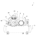
- FIG. 1 is a schematic diagram of a compressor of Example 1 of the present invention
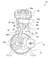
- FIG. 2 is a partial cross-sectional view of the compressor main body of Example 1.
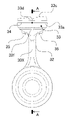
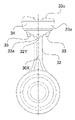
- FIG. 4 is a front view of a configuration example of a piston and a connecting rod in Example 1.
- FIG. 4 is a rear view of a configuration example of a piston and a connecting rod in Example 1.
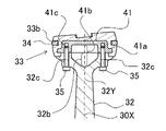
- FIG. 3B is a partial cross-sectional view taken along line AA of FIG. 3A in Example 1.
- FIG. 3B is a partial cross-sectional view taken along line BB of FIG. 3C in Example 1.
- FIG. FIG. 10 is a front view of a configuration example of a piston and a connecting rod in Example 2;
- FIG. 10 is a front view of a configuration example of a piston and a connecting rod in Example 2;
- FIG. 11 is a rear view of a configuration example of a piston and a connecting rod in Example 2; 4B is a partial cross-sectional view taken along line AA of FIG. 4A in Example 2.
- FIG. FIG. 4C is a partial cross-sectional view taken along the line BB of FIG. 4C in Example 2;
- FIG. 11 is a partial cross-sectional view of a configuration example of a piston and a connecting rod in Example 3;
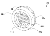
- FIG. 11 is a perspective view of a piston provided with cooling members (cooling fins) in Example 3 as viewed from the back side;
- FIG. 11 is a perspective view of a piston provided with a cooling member (cooling pin) in Example 3, as viewed from the back side; 4 is a partial cross-sectional view showing the flow of intake gas in the vicinity of the cylinder head of Example 1.
- FIG. 4 is a plan view of an example of a cylinder plate in Embodiment 1.
- FIG. 4 is a rear view of an example of a cylinder plate in Embodiment 1.
- FIG. FIG. 11 is a partial cross-sectional view showing flows of intake gas and discharge gas in the vicinity of the cylinder head in a modified example;
- Example 1 A first embodiment of the compressor of the present invention will be described with reference to FIGS. 1 to 3D.
- FIG. 1 is a schematic diagram of a compressor 1 in Example 1.
- FIG. 2 is a partial cross-sectional view of the compressor main body 10 in this embodiment.
- the compressor 1 shown in FIG. 1 includes a compressor main body 10, an electric motor 2 for driving the compressor main body 10, and a tank 3 for storing the gas discharged by the compressor main body 10.
- the compressor body 10 compresses gas such as air by means of a piston 33 that reciprocates within a cylinder.
- the compressor main body 10 includes a crankshaft 24, a crankcase 21 that supports the crankshaft 24 so as to be rotatable around a rotation center axis 24a, and one crankcase 21 that vertically protrudes from the crankcase 21. It includes a cylinder 22 , a connecting rod 32 whose base end is rotatably connected to the crankpin of the crankshaft 24 , and a piston 33 fixed to the tip end of the connecting rod 32 .
- the cylinder 22 includes a cylindrical cylinder body 25 , a cylinder plate 26 closing an end (upper end) of the cylinder body 25 , and a cylinder head 23 .
- the cylinder plate 26 is held between the cylinder head 23 and the cylinder body 25 .
- a compression chamber 22 ⁇ /b>X is formed by the piston 33 , the cylinder inner wall surface 22 a that is the inner peripheral surface of the cylinder main body 25 , and the cylinder plate 26 .
- the cylinder plate 26 has an intake port 26AG (see FIGS. 6 and 7A) for introducing gas into the compression chamber 22X, and a discharge port 26BG (see FIG. 7B) for discharging the gas compressed in the compression chamber 22X. is provided.
- An intake valve 26a (see FIGS. 6 and 7B) is attached to the intake port 26AG, and a discharge valve 26b (see FIG. 7A) is attached to the discharge port 26BG.
- the cylinder plate 26 is arranged on the opposite side of the crankshaft 24 with the piston 33 interposed therebetween.
- the piston 33 reciprocates while swinging in the cylinder 22 as the crankshaft 24 rotates.
- 30X is generally slanted.
- the electric motor 2 rotates the crankshaft 24 to give a rotational force to one end of the connecting rod 32 , and the piston 33 installed inside the cylinder 22 reciprocates inside the cylinder 22 .
- the intake stroke in which the piston 33 moves from the top dead center to the bottom dead center, the compression chamber 22X is expanded, and the intake valve 26a (see FIGS. 6 and 7B) provided in the cylinder plate 26 is opened to open the intake air in the cylinder head 23. Gas is sucked into the compression chamber 22X from the chamber through the intake port 26AG.
- FIG. 6 is a partial cross-sectional view showing the flow of intake gas near the cylinder plate 26 in this embodiment.
- FIG. 7A is a plan view of one example of the cylinder plate 26 in this embodiment.
- FIG. 7B is a rear view of one example of the cylinder plate 26 in this embodiment.
- an intake valve 26a arranged on the cylinder plate 26 for opening and closing the intake port 26AG and a discharge valve 26b for opening and closing the discharge port 26BG are arranged in accordance with the reciprocating motion of the piston 33. to operate.
- the shape of the compressor is a one-cylinder, one-stage compressor having only one pair of piston and cylinder.
- the compressor 1 may be configured to have a plurality of sets of pistons and cylinders in series or radially with respect to the crankshaft.
- the compressor main body 10 is arranged and fixed on the tank 3 with the crankshaft 24 arranged parallel to the rotating shaft of the electric motor 2 . As shown in FIG. 1, the compressor pulley 4 is fixed to the crankshaft 24 . An electric motor pulley 5 is fixed to the rotating shaft of the electric motor 2 .
- the compressor pulley 4 attached to the compressor main body 10 has blades, and generates wind toward the compressor main body 10 as it rotates, thereby promoting heat dissipation from the compressor main body 10 .
- a transmission belt 6 for transmitting power between the compressor pulley 4 and the electric motor pulley 5 is wound around the compressor pulley 4 and the electric motor pulley 5 .
- the crankshaft 24 of the compressor main body 10 is rotationally driven via the electric motor pulley 5, the transmission belt 6 and the compressor pulley 4, and the compressor main body 10 compresses the gas.
- the compressor main body 10 is connected to the electric motor 2 via the transmission belt 6, but the connection method is not limited to this.
- the crankshaft 24 of the compressor main body 10 and the rotation shaft of the electric motor 2 may be directly connected using connecting means such as a coupling.
- the compressor main body 10 shown in FIG. 2 employs an oscillating piston system in which the piston 33 is integrated with the connecting rod 32 .
- the piston 33 reciprocates while rocking in the cylinder 22 as the crankshaft 24 rotates.
- FIG. 3A is a front view of a configuration example of a piston and a connecting rod in this embodiment
- FIG. 3B is a rear view
- FIG. 3C is a partial cross-sectional view taken along line AA in FIG. 3A
- FIG. 3D is a partial cross-sectional view taken along line BB of FIG. 3C.
- the piston 33 shown in FIGS. 3A and 3B is a component separate from the connecting rod 32 that supports the piston 33 .
- the outer peripheral surface 33a that contacts the inner peripheral side of the cylinder body 25 and the piston upper surface 33c on the cylinder plate 26 side are made of resin having wear resistance.
- the piston 33 except for a piston insert 41 (see FIG. 3D), which will be described later, is made of resin with excellent wear resistance.
- a resin material excellent in wear resistance that can constitute the piston 33 is, for example, polytetrafluoroethylene (PTFE). Furthermore, when the coefficient of thermal expansion is considered, the resin material of the piston 33 may be polyphenylene sulfide (PPS) or the like.
- PTFE polytetrafluoroethylene
- PPS polyphenylene sulfide
- the outer peripheral surface 33a of the piston 33 is a spherical surface having a diameter slightly smaller than the diameter of the inner peripheral side of the cylinder main body 25.
- the center of the outer peripheral surface 33a having the spherical shape is the outer peripheral center 33d (see FIGS. 3A and 3C).
- a piston convex portion 33e is formed on an outer peripheral portion facing the connecting rod 32 of the surface of the piston 33 on the connecting rod 32 side, and is fitted with the connecting rod convex portion 32d of the connecting rod 32.
- a ring groove 33b is provided on the outer circumference of the piston 33 in contact with the cylinder inner wall surface 22a, and a piston ring 34 is fitted therein.
- the piston ring 34 is a seal ring that seals a gap between the cylinder inner wall surface 22 a and the outer peripheral surface 33 a of the piston 33 .
- the piston 33 is molded with a piston insert 41 made of metal such as an aluminum alloy embedded therein.
- the piston insert 41 prevents the piston 33 from coming off the connecting rod 32 even if the piston 33 is lifted toward the cylinder head 23 by reciprocating inertial force or frictional force and receives a load.
- the edge 41a of the piston insert 41 has a shape that bites into the piston 33 in the circumferential direction so that the piston 33 does not slip out.
- the piston insert 41 is formed with one or more, two in this embodiment, female screw holes 41c opening toward the crankcase 21 so that the connecting rod 32 can be fixed with screws.
- the piston 33 is fastened (fixed) to the connecting rod 32 from the crankcase 21 side with two screws 35 located in a direction orthogonal to the crankshaft 24 .
- the connecting rod 32 shown in FIG. have.
- the piston insert 41 of this embodiment has a dish shape with the cylinder head 23 side as the bottom.
- the seating surface of the connecting rod 32 is formed with a connecting rod recess 32b recessed toward the crankshaft 24 (downward in the drawing) at a position corresponding to the center recess of the piston insert 41.
- a hollow portion 41 b is formed between the lower surface of the piston insert 41 and the upper surface of the connecting rod 32 .
- the hollow portion 41 b is covered with a piston insert 41 on the upper surface of the piston 33 .
- the internal space of the hollow portion 41b is a closed space.
- the resin itself constituting the piston 33 receives a gas load when the piston 33 reciprocates. It is preferable to take some countermeasures.
- the female screw hole 41c of the piston insert 41 is provided parallel to the direction of the central axis 30X of the piston and connecting rod.
- the arrangement of these parts is not limited to "the arrangement parallel to the central axis 30X of the piston and connecting rod".
- the female threaded hole can be arranged obliquely with respect to the central axis 30X of the piston and connecting rod.
- the hollow portion 41b is formed between the piston 33 and the connecting rod 32, so that the mass of the reciprocating portion including the piston 33 and the connecting rod 32 can be reduced. Therefore, the vibration of the compressor body 10 caused by the reciprocating motion inertia force is suppressed.
- the upper surface of the piston 33 of the hollow portion 41b is covered with the piston insert 41. Therefore, since the piston 33 is held from the inside by the piston insert 41, even when the hollow portion 41b is formed, the amount of deformation caused by the shrinkage of the piston 33 during molding and expansion due to compression heat during operation is reduced. will be reduced.
- crankcase 21 is provided with a breathing hole (not shown) that is open to the outside air.
- a breathing hole (not shown) that is open to the outside air.
- a breathing filter 27 (see FIG. 2) is attached to the breathing hole to filter the outside air flowing into the space of the crankcase 21 in order to prevent dust from being sucked in.
- the connecting portion between the connecting rod 32 and the piston 33 has a large cross-sectional shape by providing the hollow portion 41b.
- the cross-sectional shape of the connecting rod 32 in this embodiment is substantially Y-shaped, and the angle of the root portion on the crankshaft side is in the range of about 90° to about 110° across the central axis 30X of the piston and the connecting rod. I wish I had.
- the connecting rod concave portion 32b in this embodiment has a mortar shape or a truncated cone shape.
- the gap between the inner wall surfaces facing in the radial direction where the screw 35 is installed that is, It has a slightly narrow inner dimension.
- the compressor 1 of this embodiment includes a cylinder 22 having at least a cylindrical cylinder body 25 and a cylinder plate 26 closing the end of the cylinder body 25, and a piston 33 reciprocating within the cylinder 22. , a connecting rod 32 that supports a piston 33 and a crankshaft 24 that imparts rotational force to the end of the connecting rod 32 .
- the piston 33 is an oscillating piston that reciprocates while oscillating within the cylinder 22 as the crankshaft 24 rotates.
- At least the surface of the piston 33 that contacts the inner circumference of the cylinder body 25 is made of wear-resistant resin.
- An outer peripheral surface 33a of the piston 33 is spherical.
- a compression chamber 22X is formed by the piston 33, the cylinder body 25, and the cylinder plate 26. As shown in FIG.
- a hollow portion 41b is formed between the piston 33 and the connecting rod 32, and an intake port 26AG for introducing gas into the compression chamber 22X is arranged in the cylinder plate .
- the piston 33 of Embodiment 1 of the present invention described above is an oscillating piston that reciprocates while oscillating within the cylinder 22 as the crankshaft 24 rotates.
- the outer peripheral surface 33a of the piston 33 which contacts the inner peripheral side of the cylinder main body 25, is made of a wear-resistant resin.
- the outer peripheral surface 33 a of the piston 33 is a resin spherical surface having a diameter smaller than that of the cylinder main body 25 .
- a portion of the spherical surface having a diameter larger than the diameter of the cylinder body 25 may be the outer peripheral surface 33 a of the piston 33 . Compression heat received by the upper surface 33c of the piston is shielded by the resin outer peripheral surface 33a of the piston 33. As shown in FIG.
- the gap between the outer peripheral surface 33a of the piston 33 and the inner wall surface 22a (see FIG. 2) of the piston 33 can be kept very small in an oscillating piston type compressor. , the effect that the piston 33 can slide smoothly is obtained. In addition, it is possible to prevent deformation and damage of the piston ring 34 and deterioration of sealing performance due to an increase in the swing angle.
- the mass of the reciprocating portion including the piston 33 and the connecting rod 32 can be reduced. Therefore, the vibration of the compressor body 10 caused by the reciprocating motion inertia force is suppressed.
- volumetric efficiency can be improved by sucking non-expanded gas, such as normal temperature air, from the intake port 26AG provided in the cylinder plate 26 .
- compression efficiency can be improved.
- the connecting rod 32 of this embodiment is formed in a substantially Y shape, it has higher mechanical rigidity than the substantially T-shaped connecting rod in the prior art, and the connecting rod 32 due to the locking phenomenon of the reciprocating portion is more stable. 32 has a structure in which breakage or the like is less likely to occur. Therefore, the reliability of the joint between the connecting rod 32 and the piston 33 in the compressor 1 can be enhanced.
- the compressor 1 of the present embodiment can operate more stably than the compressor of the prior art, in which the connection between the connecting rod and the piston is solid.
- Example 2 will be described with reference to FIGS. 4A to 4D.
- the same reference numerals are assigned to the same configurations as in the first embodiment, and the description thereof is omitted. The same applies to the following examples.
- FIG. 4A is a front view of a configuration example of a piston and a connecting rod in this embodiment
- FIG. 4B is a rear view
- FIG. 4C is a partial cross-sectional view taken along line AA in FIG. 4A
- FIG. 4D is a partial cross-sectional view taken along line BB of FIG. 4C.
- the internal space of the hollow portion 41b is a closed space.
- the space of the crankcase 21 is provided on the upper end surface side of the connecting rod 32 in contact with the hollow portion 41b in contrast to the first embodiment. and the hollow portion 41b are provided with two communication holes 32e and 32f.
- the shape of the opening of the communication hole 32e in this embodiment is substantially fan-shaped, and the center point thereof is located near the substantially Y-shaped root 32Y of the connecting rod 32. As shown in FIG. 4B, the shape of the opening of the communication hole 32e in this embodiment is substantially fan-shaped, and the center point thereof is located near the substantially Y-shaped root 32Y of the connecting rod 32. As shown in FIG. 4B, the shape of the opening of the communication hole 32e in this embodiment is substantially fan-shaped, and the center point thereof is located near the substantially Y-shaped root 32Y of the connecting rod 32.
- a substantially fan-shaped arc portion of the communication hole 32 e faces the piston 33 .
- the shape of the opening of the communication hole 32f is substantially semicircular or part of a circular shape.
- the hollow portion 41b The volume can be set large. Accordingly, the weight of the connecting rod 32 is reduced.
- the upper surface side of the connecting rod 32 vent holes 32e, 32f of the required size are arranged.
- the cross-sectional shape of the communication hole 32e may be circular or elliptical.
- the communication hole 32e is arranged so as to face the communication hole 32f across the central axis 30X of the piston and the connecting rod in the cross section of the piston 33 in the radial direction.
- the cross-sectional shape of the communication hole 32f which serves as a gas ejection port when the piston 33 descends, may be an elongated hole or an elliptical shape. Further, a plurality of communication holes 32f may be arranged in an angular range of about 10° to 30° in the radial direction of the piston 33.
- the opening surfaces of the communication holes 32e and 32f are provided in different directions. is particularly preferred.
- a plurality of communication holes it is preferable that at least one of them opens toward the crankshaft 24 like the communication hole 32e. Moreover, it is preferable that at least one is open in the radial direction of the cylinder main body 25 like the communication hole 32f. Further, when a plurality of communication holes are provided, it is particularly preferable that at least one of them opens toward the crankshaft 24 and at least one opens in the radial direction of the cylinder body 25 .
- crankcase 21 is provided with a breathing hole (not shown) that is open to the outside air, and a breathing filter 27 is attached to the breathing hole to prevent dust from being sucked in. ing.
- the communication hole 32e serves as an intake for taking the gas inside the crankcase 21 into the hollow portion 41b when the piston 33 descends.
- the communication hole 32f serves as an ejection port for ejecting the gas inside the hollow portion 41b to the outside when the piston 33 descends.
- the communication holes 32e and 32f are different in the opening direction from the inner hollow portion 41b to the outside.
- the opening of the communication hole 32e which serves as a gas intake port
- the opening of the communication hole 32f which serves as a gas outlet, faces radially outward of the cylinder body 25.
- the outer peripheral surface 33a of the piston 33 which contacts the inner peripheral side of the cylinder body 25, is made of a wear-resistant resin, and has a diameter smaller than that of the cylinder body 25. It is a spherical surface made of resin. As a result, the compression heat received by the piston upper surface 33 c is shielded by the piston 33 .
- the space of the hollow portion 41b and the space of the crankcase 21 are communicated with each other through the communication holes 32f and 32e.
- the hollow portion 41b is cooled by the gaseous cooling air 42 (see FIG. 4C).
- the compressor 1 of the present embodiment can prevent the deformation of the piston ring 34 more than the conventional compressor in which the connection portion between the connecting rod and the piston is solid.
- the good slidability of the spherical outer peripheral surface 33a improves the sealing performance.
- the volumetric efficiency is improved, and more stable operation can be performed.
- compression efficiency can be improved.
- heat transfer to the connecting rod 32 is less likely to occur, so the life of the bearing of the connecting rod 32 is lengthened.
- Example 3 will be described with reference to FIGS. 5A to 5C.
- a cooling member for promoting heat dissipation is further provided on the back surface 41d of the piston insert, unlike the second embodiment, so as to enhance the cooling effect in the hollow portion 41b and further promote the heat dissipation of the piston 33. It is
- FIG. 5A is a partial cross-sectional view of a configuration example of the piston and connecting rod in this embodiment when viewed from the AA section line in the front view shown in FIG. 4A.
- a cooling member (cooling pin 41f) is provided on the back surface 41d of the piston insert of the piston 33 .
- FIG. 5B is a perspective view of the piston 33 including a piston insert rear surface 41d provided with cooling fins 41e used as a cooling member, viewed from the rear surface side.
- the plurality of cooling fins 41e be arranged so that the direction of arrangement thereof follows the flow of the cooling air 42 in the inner space of the hollow portion 41b.
- FIG. 5C is a perspective view of the piston 33 including a piston insert rear surface 41d provided with a cooling pin 41f used as a cooling member, viewed from the rear surface side.
- the piston insert 41 is provided with a large number of cooling pins 41f projecting from the piston insert back surface 41d as cooling members. In this form, a large number of cooling pins 41f are arranged in a zigzag pattern. When this cooling pin 41f is used, a large amount of gas contacts around one cooling pin 41f. Therefore, the dependence of the cooling efficiency on the gas flow direction in the internal space of the hollow portion 41b is reduced.
- a breathing hole (not shown) installed in the crankcase 21 and a breathing filter 27 for filtration are attached in the same manner as in the second embodiment.
- the outer peripheral surface 33a of the piston 33 is made of resin, the compression heat generated inside the cylinder 22 is shielded by the piston 33. Further, since the hollow portion 41b is formed between the piston 33 and the connecting rod 32, the mass of the reciprocating portion including the piston 33 and the connecting rod 32 is reduced. Therefore, the vibration of the compressor main body 10 caused by the reciprocating motion inertia force can be improved.
- cooling fins 41e or cooling pins 41f are provided on the back surface 41d of the piston insert as cooling members for promoting heat dissipation from the piston 33. These cooling members increase the amount of heat released from the piston insert back surface 41d.
- the compressor 1 of this embodiment includes a metal piston insert 41 having a female screw hole 41c inside the piston 33, and the piston insert 41 is fixed to the connecting rod 32 from the crankcase 21 side with a screw 35. , a hollow portion 41 b is formed between the piston insert 41 and the connecting rod 32 . Therefore, the mass of the reciprocating portion including the piston 33 and connecting rod 32 is reduced.
- An intake port 26AG connected to the compression chamber 22X is installed in the cylinder plate 26, and the space of the hollow portion 41b and the space of the crankcase 21 are communicated through communication holes 32f and 32e. Therefore, heat dissipation from the piston 33 is promoted.
- the surface of the piston insert 41 on the side of the crankcase 21, that is, the back surface 41d of the piston insert, has cooling fins 41e and cooling pins 41f, which are cooling members that promote heat dissipation. Therefore, heat dissipation from the piston 33 is further facilitated as compared with the case where the piston insert 41 is not provided with a cooling member.
- the life of the bearing of the connecting rod 32 is relatively longer than that of the second embodiment described above.
- the cylinder plate 26 is provided with a discharge port 26BG and a discharge valve 26b for opening and closing the discharge port 26BG.
- the compressed gas discharged from the discharge port 26BG is delivered to the tank 3 through the external piping 7 from the discharge port 26BO.
- Gas is supplied to the inside of the cylinder body 25 from an intake port 26AG provided on the side surface of the end of the cylinder body 25 .
- the intake valve 26a operates to open and close the plurality of intake ports 26AG.
- the intake port 26AG is arranged below the top dead center of the piston 33 in the axial direction of the cylinder body 25 . That is, since the intake port 26AG is arranged below the top of the piston 33 at the top dead center, the intake port 26AG is exposed to the compression chamber 22X when the piston 33 is located at the top dead center. never
- the discharge port 26BG attached to the cylinder plate 26 and the intake port 26AG provided on the side surface of the end of the cylinder body 25 are located on the opposite side of the crankshaft 24 with the piston 33 interposed therebetween. are placed in
- the intake port 26AG is arranged below the top dead center of the piston 33 in the axial direction of the cylinder body 25 . Therefore, the volumetric efficiency is further improved when the external gas is sucked and compressed.
- the intake and discharge mechanism of this modified example can be used in combination with the configuration of the piston and connecting rod in the first to third embodiments described above. In that case, even if the compression rate of the gas is set higher, if the hollow portion 41b is provided in the piston and the connecting rod to promote heat dissipation from the hollow portion 41b on the back side of the piston 33, the compressor 1 of this modification can be obtained. can maintain high volumetric efficiency. As a result, compression efficiency is increased.
- the compressor 1 of this modified example has improved sealing performance and maintains volumetric efficiency even when the compression rate is set high compared to the compressor of the prior art in which the connection portion between the connecting rod and the piston is solid. and more stable operation. Also, since the piston 33 can be efficiently cooled, the service life of the bearing of the connecting rod 32 is extended.
- the compressor of the present invention can be applied to various compressors that can employ the oscillating piston system among compressors that compress various gases such as air and refrigerants, and the types, models, and applications thereof are particularly limited. not.
- the present invention is not limited to the above examples, and includes various modifications. The above embodiments have been described in detail for easy understanding of the present invention, and are not necessarily limited to those having all the described configurations.
- Discharge port 27 Breathing filter 30X Central axis of piston and connecting rod 32 Connecting rod 32b Connecting rod concave portion 32c Screw through hole 32d Connecting rod convex portion 32e Communicating hole 32f Communicating hole 33 Piston 33a Outer peripheral surface 33b Ring groove 33c Upper surface of piston 33d Center of outer peripheral portion 33e Piston convex portion 34 Piston ring 35 Screw 41 Piston insert 41a Edge 41b ...Hollow portion 41c...Female screw hole 41d...Back side of piston insert 42...Cooling air
Landscapes
- Engineering & Computer Science (AREA)
- Mechanical Engineering (AREA)
- General Engineering & Computer Science (AREA)
- Compressor (AREA)
Abstract
Description
本発明の圧縮機の実施例1について図1から図3Dを参照し説明する。
実施例2について図4Aから図4Dを参照し説明する。実施例1と同じ構成には同一の符号を付し、説明は省略する。以下の実施例においても同様とする。
実施例3について図5Aから図5Cを参照し説明する。本実施例には、中空部41bにおける冷却効果を増強し、ピストン33の放熱をより促進できるように、実施例2に対して、ピストンインサート裏面41dに放熱を促進するための冷却部材がさらに備えられている。
変形例について図8を参照し説明する。本変形例は、シリンダ本体25の内部へ気体を供給する吸気弁26aと吸気口26AGの構造が、シリンダプレート26に吸気口26AGを備えた実施例1、実施例2、及び実施例3と異なっている。
なお、本発明の圧縮機は空気や冷媒などの各種気体を圧縮する圧縮機のうち、揺動ピストン方式を採用しうる様々な圧縮機に適用可能であり、その種類や型式、用途は特に限定されない。本発明は、上記の実施例に限定されるものではなく、様々な変形例が含まれる。上記の実施例は本発明を分かりやすく説明するために詳細に説明したものであり、必ずしも説明した全ての構成を備えるものに限定されるものではない。
Claims (11)
- 円筒状のシリンダ本体、及び前記シリンダ本体の端部を閉鎖するシリンダプレートを少なくとも有するシリンダと、
前記シリンダ内を往復動するピストンと、
前記ピストンを支持するコンロッドと、
前記コンロッドの端部に回転力を与えるクランクシャフトと、
を備え、
前記ピストンは、前記クランクシャフトの回転に伴い前記シリンダ内を揺動しながら往復動する揺動ピストンであって、
前記ピストンは、少なくとも、前記シリンダ本体の内周側に接触する面が耐摩耗性を有する樹脂によって構成され、
前記ピストンの外周面は球面となっており、
前記ピストンと前記シリンダ本体と前記シリンダプレートによって圧縮室が形成され、
前記ピストンと前記コンロッドの間に中空部が形成され、
前記圧縮室に気体を導入するための吸気口が、前記シリンダプレートまたは前記シリンダ本体の端部の側面に配置されている圧縮機。 - 請求項1に記載の圧縮機において、
前記クランクシャフトを回転可能に支持するクランクケースが備えられ、
前記中空部の空間と前記クランクケースの空間とが連通孔によって連通されている圧縮機。 - 請求項2に記載の圧縮機において、
前記ピストンの内部に、メネジ穴を有する金属製のピストンインサートが備えられ、
前記ピストンインサートが前記コンロッドに対して前記クランクケースの側からネジで固定され、
前記中空部は、前記ピストンインサートと前記コンロッドの間に形成されている圧縮機。 - 請求項3に記載の圧縮機において、
前記ピストンインサートの前記クランクケースの側の面に、放熱を促す冷却部材を有する圧縮機。 - 請求項4に記載の圧縮機において、
前記冷却部材が、冷却フィンまたは冷却ピンである圧縮機。 - 請求項2に記載の圧縮機において、
前記連通孔は、2つ以上設けられている圧縮機。 - 請求項6に記載の圧縮機において、
前記連通孔は、そのうち少なくとも1つが前記クランクシャフトの側に開口している圧縮機。 - 請求項6に記載の圧縮機において、
前記連通孔は、そのうち少なくとも1つが前記シリンダ本体の径方向に開口している圧縮機。 - 請求項6に記載の圧縮機において、
前記連通孔のうち少なくとも一つが前記クランクシャフトの側に開口し、そのうち少なくとも1つが前記シリンダ本体の径方向に開口している圧縮機。 - 請求項1に記載の圧縮機において、
前記吸気口が前記シリンダプレートに配置されている圧縮機。 - 請求項1に記載の圧縮機において、
前記吸気口が前記シリンダ本体の端部の側面に配置されている圧縮機。
Priority Applications (2)
| Application Number | Priority Date | Filing Date | Title |
|---|---|---|---|
| CN202180051831.XA CN116113764B (zh) | 2021-01-20 | 2021-11-24 | 压缩机 |
| KR1020237005062A KR102758518B1 (ko) | 2021-01-20 | 2021-11-24 | 압축기 |
Applications Claiming Priority (2)
| Application Number | Priority Date | Filing Date | Title |
|---|---|---|---|
| JP2021007056A JP7681976B2 (ja) | 2021-01-20 | 2021-01-20 | 圧縮機 |
| JP2021-007056 | 2021-01-20 |
Publications (1)
| Publication Number | Publication Date |
|---|---|
| WO2022158111A1 true WO2022158111A1 (ja) | 2022-07-28 |
Family
ID=82548742
Family Applications (1)
| Application Number | Title | Priority Date | Filing Date |
|---|---|---|---|
| PCT/JP2021/043065 Ceased WO2022158111A1 (ja) | 2021-01-20 | 2021-11-24 | 圧縮機 |
Country Status (4)
| Country | Link |
|---|---|
| JP (1) | JP7681976B2 (ja) |
| KR (1) | KR102758518B1 (ja) |
| CN (1) | CN116113764B (ja) |
| WO (1) | WO2022158111A1 (ja) |
Cited By (1)
| Publication number | Priority date | Publication date | Assignee | Title |
|---|---|---|---|---|
| WO2024047989A1 (ja) * | 2022-09-02 | 2024-03-07 | 株式会社日立産機システム | 圧縮機 |
Citations (5)
| Publication number | Priority date | Publication date | Assignee | Title |
|---|---|---|---|---|
| EP0312597A1 (de) * | 1987-04-21 | 1989-04-26 | Proizvodstvennoe Obiedinenie 'zavod Imeni M.I.Kalinina' | Volumenverdrängungsmaschinenkolben |
| US5231917A (en) * | 1992-09-14 | 1993-08-03 | Devilbiss Air Power Company | Wobble piston |
| JPH06159246A (ja) * | 1992-11-20 | 1994-06-07 | Tokico Ltd | 往復動圧縮機 |
| US20070151445A1 (en) * | 2005-12-30 | 2007-07-05 | Chi-Ming Chen | Piston structure for an air pump |
| JP2014029155A (ja) * | 2013-09-20 | 2014-02-13 | Hitachi Industrial Equipment Systems Co Ltd | 往復動圧縮機 |
Family Cites Families (8)
| Publication number | Priority date | Publication date | Assignee | Title |
|---|---|---|---|---|
| CN101205878A (zh) * | 2006-12-18 | 2008-06-25 | 乐金电子(天津)电器有限公司 | 封闭式压缩机的压缩结构部 |
| JP2008248812A (ja) | 2007-03-30 | 2008-10-16 | Hitachi Ltd | 往復動圧縮機 |
| RU2362893C2 (ru) * | 2007-10-05 | 2009-07-27 | Павел Игнатьевич Загуменнов | Однокамерный многоцилиндровый двигатель внутреннего сгорания со встречнодвижущимися поршнями |
| CN101900098B (zh) * | 2009-05-27 | 2015-06-24 | 株式会社日立产机系统 | 往复运动压缩机 |
| JP5108977B1 (ja) * | 2012-01-23 | 2012-12-26 | シナノケンシ株式会社 | 圧縮機又は真空機 |
| JP2017031915A (ja) * | 2015-08-04 | 2017-02-09 | サンデン・エンバイロメントプロダクツ株式会社 | ピストンアセンブリ及びこれを備えた往復動圧縮機 |
| CN207111355U (zh) * | 2017-08-01 | 2018-03-16 | 耐力股份有限公司 | 一种无油空压机活塞 |
| CN209586619U (zh) * | 2018-12-07 | 2019-11-05 | 江苏赫缘科技有限公司 | 一种活塞式压缩机 |
-
2021
- 2021-01-20 JP JP2021007056A patent/JP7681976B2/ja active Active
- 2021-11-24 KR KR1020237005062A patent/KR102758518B1/ko active Active
- 2021-11-24 WO PCT/JP2021/043065 patent/WO2022158111A1/ja not_active Ceased
- 2021-11-24 CN CN202180051831.XA patent/CN116113764B/zh active Active
Patent Citations (5)
| Publication number | Priority date | Publication date | Assignee | Title |
|---|---|---|---|---|
| EP0312597A1 (de) * | 1987-04-21 | 1989-04-26 | Proizvodstvennoe Obiedinenie 'zavod Imeni M.I.Kalinina' | Volumenverdrängungsmaschinenkolben |
| US5231917A (en) * | 1992-09-14 | 1993-08-03 | Devilbiss Air Power Company | Wobble piston |
| JPH06159246A (ja) * | 1992-11-20 | 1994-06-07 | Tokico Ltd | 往復動圧縮機 |
| US20070151445A1 (en) * | 2005-12-30 | 2007-07-05 | Chi-Ming Chen | Piston structure for an air pump |
| JP2014029155A (ja) * | 2013-09-20 | 2014-02-13 | Hitachi Industrial Equipment Systems Co Ltd | 往復動圧縮機 |
Cited By (1)
| Publication number | Priority date | Publication date | Assignee | Title |
|---|---|---|---|---|
| WO2024047989A1 (ja) * | 2022-09-02 | 2024-03-07 | 株式会社日立産機システム | 圧縮機 |
Also Published As
| Publication number | Publication date |
|---|---|
| JP2022111556A (ja) | 2022-08-01 |
| CN116113764B (zh) | 2025-07-04 |
| CN116113764A (zh) | 2023-05-12 |
| KR102758518B1 (ko) | 2025-01-23 |
| KR20230035413A (ko) | 2023-03-13 |
| JP7681976B2 (ja) | 2025-05-23 |
Similar Documents
| Publication | Publication Date | Title |
|---|---|---|
| CN101900098B (zh) | 往复运动压缩机 | |
| KR930006370B1 (ko) | 냉매압축기에서의 피스톤용 피스톤링 | |
| CN113915129B (zh) | 一种低压腔旋转式压缩机及空调器 | |
| WO2022158111A1 (ja) | 圧縮機 | |
| JP7554044B2 (ja) | 圧縮機 | |
| CN206972516U (zh) | 涡旋压缩机 | |
| US20180195503A1 (en) | Fluid compressor | |
| JP7576937B2 (ja) | 圧縮機 | |
| JP2008297924A (ja) | 往復動式ガス圧縮機 | |
| KR100687639B1 (ko) | 압축기 | |
| JP7132721B2 (ja) | 往復動圧縮機 | |
| US5937736A (en) | Wobble piston with cooling fins extending through slots formed in the piston head | |
| JP2004183534A (ja) | 圧縮機 | |
| JP7709286B2 (ja) | 往復動圧縮機 | |
| JP2005188407A (ja) | ピストン式圧縮機における断熱構造 | |
| CN1508425A (zh) | 具有包括带特别设计曲面的阀座圈的排出阀机构的压缩机 | |
| JP2024035464A (ja) | 圧縮機 | |
| JP2021110274A (ja) | 圧縮機、ピストン、およびコンロッド | |
| CN118591690A (zh) | 压缩机 | |
| KR101592692B1 (ko) | 압축기용 밸브 구조 | |
| JP2005042624A (ja) | 圧縮機 | |
| KR102579202B1 (ko) | 왕복동식 압축기 | |
| JPH08121330A (ja) | 往復動型圧縮機 | |
| JP2006207391A (ja) | 流体機械 | |
| JP2004156571A (ja) | 気体圧縮機 |
Legal Events
| Date | Code | Title | Description |
|---|---|---|---|
| 121 | Ep: the epo has been informed by wipo that ep was designated in this application |
Ref document number: 21921214 Country of ref document: EP Kind code of ref document: A1 |
|
| ENP | Entry into the national phase |
Ref document number: 20237005062 Country of ref document: KR Kind code of ref document: A |
|
| WWE | Wipo information: entry into national phase |
Ref document number: 202317017733 Country of ref document: IN |
|
| NENP | Non-entry into the national phase |
Ref country code: DE |
|
| 122 | Ep: pct application non-entry in european phase |
Ref document number: 21921214 Country of ref document: EP Kind code of ref document: A1 |
|
| WWG | Wipo information: grant in national office |
Ref document number: 202180051831.X Country of ref document: CN |