WO2022157877A1 - 設備位置特定システム、カバー、及び設備位置特定方法 - Google Patents
設備位置特定システム、カバー、及び設備位置特定方法 Download PDFInfo
- Publication number
- WO2022157877A1 WO2022157877A1 PCT/JP2021/002003 JP2021002003W WO2022157877A1 WO 2022157877 A1 WO2022157877 A1 WO 2022157877A1 JP 2021002003 W JP2021002003 W JP 2021002003W WO 2022157877 A1 WO2022157877 A1 WO 2022157877A1
- Authority
- WO
- WIPO (PCT)
- Prior art keywords
- vibration
- optical fiber
- aerial cable
- cable
- cover
- Prior art date
- Legal status (The legal status is an assumption and is not a legal conclusion. Google has not performed a legal analysis and makes no representation as to the accuracy of the status listed.)
- Ceased
Links
Images





Classifications
-
- G—PHYSICS
- G01—MEASURING; TESTING
- G01H—MEASUREMENT OF MECHANICAL VIBRATIONS OR ULTRASONIC, SONIC OR INFRASONIC WAVES
- G01H9/00—Measuring mechanical vibrations or ultrasonic, sonic or infrasonic waves by using radiation-sensitive means, e.g. optical means
- G01H9/004—Measuring mechanical vibrations or ultrasonic, sonic or infrasonic waves by using radiation-sensitive means, e.g. optical means using fibre optic sensors
-
- G—PHYSICS
- G01—MEASURING; TESTING
- G01B—MEASURING LENGTH, THICKNESS OR SIMILAR LINEAR DIMENSIONS; MEASURING ANGLES; MEASURING AREAS; MEASURING IRREGULARITIES OF SURFACES OR CONTOURS
- G01B11/00—Measuring arrangements characterised by the use of optical techniques
-
- G—PHYSICS
- G01—MEASURING; TESTING
- G01B—MEASURING LENGTH, THICKNESS OR SIMILAR LINEAR DIMENSIONS; MEASURING ANGLES; MEASURING AREAS; MEASURING IRREGULARITIES OF SURFACES OR CONTOURS
- G01B11/00—Measuring arrangements characterised by the use of optical techniques
- G01B11/002—Measuring arrangements characterised by the use of optical techniques for measuring two or more coordinates
Definitions
- the present disclosure relates to a technique for specifying the route of an aerial cable including optical fiber by expressing it with the length of the optical fiber from the communication-intensive building.
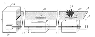
- Patent Documents 1 and 2 A technique that uses an optical fiber vibration sensor to identify the location of equipment is known (see Patent Documents 1 and 2, for example). For example, as shown in FIG. 1, if the optical fiber vibration sensing device 20 is used from the communication aggregation building 10 of the communication optical fiber 25 and the vibration of the communication optical fiber 25 is measured, if a blow 15 is caused to the cover of the manhole 30, the impact vibration will be generated. It can be measured, and the location in the longitudinal direction of the optical fiber 25 from the communication-intensive building 10 (the distance from the communication-intensive building 10 to the location to which the vibration is applied) can be specified. By confirming the measurement result, it is possible to confirm that the communication optical fiber 35 exists underground 6 at the location without opening the manhole 30, and to match the manhole position with the fiber route map.
- JP 2020-127094 A Japanese Patent Application Laid-Open No. 2020-052030
- an object of the present invention is to provide an equipment location identification system, a cover, and an equipment location identification method that can identify the route of the overhead cable without directly disturbing the overhead cable itself.
- an object of the present invention is to provide an equipment position identifying system, a cover, and an equipment position identifying method that can identify the route of an overhead cable without directly affecting the overhead cable itself.
- the facility position specifying system is a facility position specifying system that specifies the position of an overhead cable, an optical fiber along the aerial cable; a cylindrical cover that covers the aerial cable at any position in the longitudinal direction of the aerial cable; It is connected to the end of the optical fiber, and the time change of the scattered light from the optical fiber when vibration is applied from the cover to the aerial cable is measured as the scattered light intensity distribution in the longitudinal direction of the optical fiber.
- an optical measuring instrument that acquires as a time change; By specifying the vibration position on the optical fiber to which the vibration is applied based on the scattered light intensity distribution, and matching the vibration position on the optical fiber with the position on the map of the aerial cable, a signal processing unit that identifies the actual position of the aerial cable to which vibration is applied; Prepare.
- a facility position specifying method is a facility position specifying method for specifying the position of an overhead cable, covering the aerial cable with a tubular cover at any position in the longitudinal direction of the aerial cable; connecting an optical measuring instrument to the end of an optical fiber included in the overhead cable; applying vibration from the cover to the aerial cable; Acquiring the time change of the scattered light from the optical fiber when the vibration is applied as the time change of the scattered light intensity distribution in the longitudinal direction of the optical fiber; identifying a vibration position on the optical fiber to which the vibration is applied based on the scattered light intensity distribution; identifying the actual position of the aerial cable to which the vibration was applied; I do.
- a cover is attached to an arbitrary position on the overhead cable, and vibration is applied to the overhead cable through the cover. Since the facility location system (method) does not hit the overhead cable directly, fiber optic vibration sensing can be performed with less likelihood of affecting communications.
- the facility position specifying method is a facility position specifying method for specifying the position of a pillar supporting an overhead cable, connecting an optical measuring instrument to the end of an optical fiber included in the overhead cable; applying vibration to any of the columns; Acquiring the time change of the scattered light from the optical fiber when the vibration is applied as the time change of the scattered light intensity distribution in the longitudinal direction of the optical fiber; identifying a vibration position on the optical fiber to which the vibration is applied based on the scattered light intensity distribution; identifying the actual position of the pillar to which the vibration was applied; may be performed.
- the present invention can provide an equipment location identification system and an equipment location identification method that can identify the route of an overhead cable without directly disturbing the overhead cable itself.
- the cover of the facility location identification system may include a vibration mechanism that applies the vibration. That is, the cover includes a vibration mechanism that generates vibration, and a cylinder that covers the aerial cable including the optical cable at an arbitrary location and transmits the vibration to the aerial cable. Remote control is possible without the need for the operator to hit directly.
- the cover of the facility localization system may have folds on the inner wall that contact the aerial cable and transmit the vibration to the aerial cable. That is, the cover includes a tube that covers the aerial cable including the optical cable at an arbitrary location, and folds that are installed on the inner wall of the tube, come into contact with the aerial cable, and transmit the vibration of the tube to the aerial cable. Vibration from the cover can be efficiently transmitted to the aerial cable.
- the present invention can provide an equipment location identification system, a cover, and an equipment location identification method that can identify the route of an overhead cable without directly disturbing the overhead cable itself.
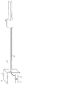
- FIG. 2 is a diagram for explaining the equipment position specifying system of this embodiment.
- This facility position specifying system is a facility position specifying system that specifies the position of the overhead cable 26, an optical fiber 25 along an overhead cable 26; a cylindrical cover 40 that covers the overhead cable 26 at any position in the longitudinal direction of the overhead cable 26; It is connected to the end of the optical fiber 25, and the time change of the scattered light from the optical fiber 25 when vibration is applied to the aerial cable 26 from the cover 40 is measured as the scattered light intensity distribution in the longitudinal direction of the optical fiber 25.
- an optical measuring instrument 20 that acquires as a change over time; By specifying the vibration position on the optical fiber 25 to which the vibration is applied based on the scattered light intensity distribution, and matching the vibration position on the optical fiber 25 with the position of the aerial cable 26 on the map, a signal processing unit 21 that identifies the actual position of the aerial cable 26 to which vibration is applied; Prepare.
- the aerial cable 26 is a cable stretched in the air by a pillar or the like.
- the overhead cable 26 is a metal wire or optical fiber cable for power supply.
- An optical fiber 25 used in this system runs along the overhead cable 26 . If the overhead cable 26 is an optical fiber cable, the optical fiber in the optical fiber cable can be used as the optical fiber 25 .
- the cover 40 is installed so as to cover the aerial cable 26.
- the cover 40 may be attached when laying the aerial cable 26, or an operator may attach the cover 40 to the aerial cable 26 for each inspection.
- the cover 40 has a function of transmitting vibration such as applied shock to the aerial cable 26 .
- the cover 40 is preferably made of a material having a high elastic modulus (high Young's modulus) and a low density, such as metal, in order to efficiently transmit vibrations to the cable.
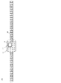
- FIG. 3A and 3B are diagrams illustrating the structure of the cover 40.
- the cover 40 is a tube 41 covering the aerial cable 26 at an arbitrary location; a fold 42 installed on the inner wall of the tube 41, in contact with the overhead cable 26, and transmitting the vibration of the tube 41 to the overhead cable 26; Prepare.
- the cover 40 covers the aerial cable 26 with the tube 41.
- the tube 41 and the overhead cable 26 are not in direct contact.
- the cover 40 has pleats 42 , and the pleats 42 contact the aerial cable 26 to create a space between the tube 41 and the aerial cable 26 . Vibrations from the tube 41 are transmitted to the aerial cable 26 via the folds 42 . Therefore, the vibration from the tube 41 can be efficiently transmitted to the aerial cable 26. - ⁇ Note that the number of pleats 42 and the length L of the cover 40 may be adjusted in order to transmit vibrations efficiently.
- FIG. 4 is a flow chart for explaining the method for specifying the location of equipment.
- This facility location identification method is Covering the aerial cable 26 with a cylindrical cover 40 at an arbitrary position in the longitudinal direction of the aerial cable 26 (step S01); connecting the optical measuring instrument 20 to the end of the optical fiber 25 included in the overhead cable 26 (step S02); applying vibration from the cover 40 to the aerial cable 26 (step S03); Acquiring the time change of the scattered light from the optical fiber 25 when the vibration is applied as the time change of the scattered light intensity distribution in the longitudinal direction of the optical fiber 25 (step S04); Identifying the vibration position on the optical fiber 25 to which the vibration is applied based on the scattered light intensity distribution (step S05); and identifying the actual position of the aerial cable 26 to which the vibration is applied (step S06); I do.
- step S01 the cover 40 is attached to the aerial cable 26 whose position is to be grasped.
- the number of covers 40 is arbitrary.
- the cover 40 may be attached when laying the aerial cable 26, or an operator may attach the cover 40 to the aerial cable 26 for each inspection.
- step S02 One end of the overhead cable 26 is drawn into the communication aggregation building 10.
- the optical fiber 25 is taken out from the aerial cable 26 drawn into the communication building 10 and connected to the optical measuring instrument 20 (the end of the optical fiber 25 connected to the optical measuring instrument 20 is defined as "one end”. ).
- the optical measuring device 20 is, for example, an OTDR (Optical Time Domain Reflectometer).
- step S03 the cover 40 vibrates during the optical test in which the test light is input from the optical measuring instrument 20 to one end of the optical fiber 25 and the backscattered light output from one end of the optical fiber 25 is measured by the optical measuring instrument 20. give.
- a method of applying vibration will be described.
- Method 1 As shown in FIG. 5, the operator applies a blow 15 to the cover with a hammer or the like. For example, an operator strikes with a long stick hammer reaching from the ground. Alternatively, the worker may move to the vicinity of the cover 40 with a baguette car and strike with a hammer.
- the cover 40 has a vibration mechanism 43 that causes the cylinder 41 to vibrate.
- the vibration mechanism 43 is arranged, for example, in the cylinder 41, and is composed of a piezoelectric element that is moved by radio waves and a battery such as a solar battery that supplies power to the piezoelectric element.
- the cover 40 is provided with the vibration mechanism 43, the operator can apply vibration remotely without getting on a baguette wheel or the like.
- FIG. 7 is a table summarizing work styles in step S03.
- the cover 40 is always attached to the aerial cable 26 and cases where the cover 40 is always attached to the aerial cable 26 during inspection.
- the cover 40 if the cover 40 is hit with a hammer or the like to apply vibration, the cover 40 does not require a vibrating mechanism, but workers must be dispatched to the work site.
- the cover 40 when the cover 40 is provided with the vibrating mechanism 43, remote control is possible and there is no need to dispatch a worker to the work site. However, if it is necessary to supply power to the vibrating mechanism 43 during work, it is necessary to dispatch a worker.
- the light measuring instrument 20 acquires the light intensity distribution of the backscattered light output from one end of the optical fiber 25.
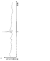
- FIG. 8 is an example of the light intensity distribution acquired by the light measuring device 20. As shown in FIG. The horizontal axis is the distance from one end of the optical fiber 25 . The vertical axis is the light intensity of the backscattered light. There is a waveform peak at the position of distance z, and it can be seen that vibration was applied at this position.
- step S06 the signal processing unit 21 compares the map 50 showing the layout of the aerial cables 26 with the light intensity distribution of FIG.
- FIG. 9 is a diagram for explaining matching work.
- the map 50 has a record of what route the overhead cable was laid when the overhead cable 26 was laid.
- the signal processing unit 21 detects the peak position (impact position 52) of the light intensity distribution in FIG. You can determine where you are on the top.
- FIG. 10 is a flow chart for explaining the method of specifying the location of equipment according to this embodiment.
- FIG. 11 is a diagram for explaining an equipment position identifying system inspected by this equipment position identifying method.
- This facility position specifying method is a method of specifying the facility position without attaching the cover 40 to the facility position specifying method of the first embodiment.
- This facility location identification method is connecting the optical measuring instrument 20 to the end of the optical fiber 25 included in the overhead cable 26 (step S02); Applying vibration to any column 35 supporting the aerial cable 26 (step S13); Acquiring the time change of the scattered light from the optical fiber 25 when the vibration is applied as the time change of the scattered light intensity distribution in the longitudinal direction of the optical fiber 25 (step S04); Identifying the vibration position on the optical fiber 25 to which the vibration is applied based on the scattered light intensity distribution (step S05); and identifying the actual position of the pillar 35 to which the vibration is applied (step S16); I do.
- the facility position identification method of this embodiment hits the pillar 35 supporting the aerial cable 26 instead of hitting the cover.
- the vibration is transmitted to the optical fiber 25 of the aerial cable 26, and the scattered light intensity distribution as shown in FIG. Therefore, as described with reference to FIG. 9, by comparing the scattered light intensity distribution with the map 50 on which the laying of the aerial cable 26 is described, the actual position (position on the map) of the pillar 35 can be specified.
- this facility position identification method does not require the work of attaching a cover to the aerial cable 26, and it is possible to simply know the position of the overhead cable 26 and the position of the utility pole. be able to.
Landscapes
- Physics & Mathematics (AREA)
- General Physics & Mathematics (AREA)
- Length Measuring Devices By Optical Means (AREA)
Priority Applications (7)
| Application Number | Priority Date | Filing Date | Title |
|---|---|---|---|
| PCT/JP2021/002003 WO2022157877A1 (ja) | 2021-01-21 | 2021-01-21 | 設備位置特定システム、カバー、及び設備位置特定方法 |
| US18/269,858 US20240060817A1 (en) | 2021-01-21 | 2021-01-21 | Equipment location identification system, cover, and equipment location identification method |
| EP21920990.5A EP4283250A4 (en) | 2021-01-21 | 2021-01-21 | SYSTEM FOR DETERMINING THE LOCATION OF A PLANT, COVER AND METHOD FOR DETERMINING THE LOCATION OF A PLANT |
| CN202180081160.1A CN116569002A (zh) | 2021-01-21 | 2021-01-21 | 设备位置确定系统、罩以及设备位置确定方法 |
| EP24217005.8A EP4495557A3 (en) | 2021-01-21 | 2021-01-21 | Equipment location identification system, cover, and equipment location identification method |
| EP24217041.3A EP4495558A3 (en) | 2021-01-21 | 2021-01-21 | Equipment location identification system, cover, and equipment location identification method |
| JP2022576290A JPWO2022157877A1 (https=) | 2021-01-21 | 2021-01-21 |
Applications Claiming Priority (1)
| Application Number | Priority Date | Filing Date | Title |
|---|---|---|---|
| PCT/JP2021/002003 WO2022157877A1 (ja) | 2021-01-21 | 2021-01-21 | 設備位置特定システム、カバー、及び設備位置特定方法 |
Publications (1)
| Publication Number | Publication Date |
|---|---|
| WO2022157877A1 true WO2022157877A1 (ja) | 2022-07-28 |
Family
ID=82548548
Family Applications (1)
| Application Number | Title | Priority Date | Filing Date |
|---|---|---|---|
| PCT/JP2021/002003 Ceased WO2022157877A1 (ja) | 2021-01-21 | 2021-01-21 | 設備位置特定システム、カバー、及び設備位置特定方法 |
Country Status (5)
| Country | Link |
|---|---|
| US (1) | US20240060817A1 (https=) |
| EP (3) | EP4283250A4 (https=) |
| JP (1) | JPWO2022157877A1 (https=) |
| CN (1) | CN116569002A (https=) |
| WO (1) | WO2022157877A1 (https=) |
Cited By (2)
| Publication number | Priority date | Publication date | Assignee | Title |
|---|---|---|---|---|
| WO2024166295A1 (ja) * | 2023-02-09 | 2024-08-15 | 日本電信電話株式会社 | 設備位置解析装置及び設備位置解析方法 |
| WO2026022889A1 (ja) * | 2024-07-22 | 2026-01-29 | Ntt株式会社 | 光線路設備位置特定方法 |
Families Citing this family (1)
| Publication number | Priority date | Publication date | Assignee | Title |
|---|---|---|---|---|
| US20220333956A1 (en) * | 2021-04-14 | 2022-10-20 | Nec Laboratories America, Inc | Mapping using optical fiber sensing |
Citations (5)
| Publication number | Priority date | Publication date | Assignee | Title |
|---|---|---|---|---|
| JPH10177055A (ja) * | 1996-12-17 | 1998-06-30 | Chubu Electric Power Co Inc | 架空送電線の事故検出位置標定システム |
| JP2017219369A (ja) * | 2016-06-06 | 2017-12-14 | 西松建設株式会社 | 加振装置、振動測定システム、振動測定方法および張力の計測方法 |
| WO2020044648A1 (ja) * | 2018-08-30 | 2020-03-05 | 日本電気株式会社 | 電柱位置特定システム、電柱位置特定装置、電柱位置特定方法、及び非一時的なコンピュータ可読媒体 |
| JP2020052030A (ja) | 2018-09-20 | 2020-04-02 | 日本電信電話株式会社 | マンホール位置特定方法及びマンホール位置特定システム |
| JP2020127094A (ja) | 2019-02-01 | 2020-08-20 | 日本電信電話株式会社 | 光ファイバルート探索方法、光ファイバルート探索装置及びプログラム |
Family Cites Families (6)
| Publication number | Priority date | Publication date | Assignee | Title |
|---|---|---|---|---|
| JP3914050B2 (ja) * | 2001-12-28 | 2007-05-16 | 日本特殊陶業株式会社 | ランジュバン型超音波振動子 |
| JP2010074938A (ja) * | 2008-09-18 | 2010-04-02 | Nippon Telegr & Teleph Corp <Ntt> | ケーブル探索方法及びケーブル探索装置 |
| JP5128519B2 (ja) * | 2009-02-24 | 2013-01-23 | 日本電信電話株式会社 | 光設備識別方法及び装置 |
| JP7211134B2 (ja) * | 2019-02-12 | 2023-01-24 | 日本電信電話株式会社 | 架空光ファイバケーブル検査方法、架空光ファイバケーブル検査装置及びプログラム |
| US12467822B2 (en) * | 2020-08-31 | 2025-11-11 | Nec Corporation | Utility pole deterioration discrimination device and method |
| WO2022113252A1 (ja) * | 2020-11-27 | 2022-06-02 | 日本電気株式会社 | 位置特定システム、振動発生器、及び位置特定方法 |
-
2021
- 2021-01-21 WO PCT/JP2021/002003 patent/WO2022157877A1/ja not_active Ceased
- 2021-01-21 US US18/269,858 patent/US20240060817A1/en not_active Abandoned
- 2021-01-21 CN CN202180081160.1A patent/CN116569002A/zh active Pending
- 2021-01-21 EP EP21920990.5A patent/EP4283250A4/en active Pending
- 2021-01-21 JP JP2022576290A patent/JPWO2022157877A1/ja active Pending
- 2021-01-21 EP EP24217041.3A patent/EP4495558A3/en not_active Withdrawn
- 2021-01-21 EP EP24217005.8A patent/EP4495557A3/en active Pending
Patent Citations (5)
| Publication number | Priority date | Publication date | Assignee | Title |
|---|---|---|---|---|
| JPH10177055A (ja) * | 1996-12-17 | 1998-06-30 | Chubu Electric Power Co Inc | 架空送電線の事故検出位置標定システム |
| JP2017219369A (ja) * | 2016-06-06 | 2017-12-14 | 西松建設株式会社 | 加振装置、振動測定システム、振動測定方法および張力の計測方法 |
| WO2020044648A1 (ja) * | 2018-08-30 | 2020-03-05 | 日本電気株式会社 | 電柱位置特定システム、電柱位置特定装置、電柱位置特定方法、及び非一時的なコンピュータ可読媒体 |
| JP2020052030A (ja) | 2018-09-20 | 2020-04-02 | 日本電信電話株式会社 | マンホール位置特定方法及びマンホール位置特定システム |
| JP2020127094A (ja) | 2019-02-01 | 2020-08-20 | 日本電信電話株式会社 | 光ファイバルート探索方法、光ファイバルート探索装置及びプログラム |
Non-Patent Citations (1)
| Title |
|---|
| See also references of EP4283250A4 |
Cited By (2)
| Publication number | Priority date | Publication date | Assignee | Title |
|---|---|---|---|---|
| WO2024166295A1 (ja) * | 2023-02-09 | 2024-08-15 | 日本電信電話株式会社 | 設備位置解析装置及び設備位置解析方法 |
| WO2026022889A1 (ja) * | 2024-07-22 | 2026-01-29 | Ntt株式会社 | 光線路設備位置特定方法 |
Also Published As
| Publication number | Publication date |
|---|---|
| US20240060817A1 (en) | 2024-02-22 |
| EP4495558A3 (en) | 2025-04-16 |
| EP4283250A1 (en) | 2023-11-29 |
| JPWO2022157877A1 (https=) | 2022-07-28 |
| EP4495557A2 (en) | 2025-01-22 |
| EP4283250A4 (en) | 2025-01-01 |
| EP4495557A3 (en) | 2025-04-02 |
| CN116569002A (zh) | 2023-08-08 |
| EP4495558A2 (en) | 2025-01-22 |
Similar Documents
| Publication | Publication Date | Title |
|---|---|---|
| US11366231B2 (en) | Smart optical cable positioning/location using optical fiber sensing | |
| WO2022157877A1 (ja) | 設備位置特定システム、カバー、及び設備位置特定方法 | |
| JP6974747B2 (ja) | マンホール位置特定方法及びマンホール位置特定システム | |
| JP7124875B2 (ja) | 電柱位置特定システム、電柱位置特定装置、電柱位置特定方法、及びプログラム | |
| Xia et al. | First proof that geographic location on deployed fiber cable can be determined by using OTDR distance based on distributed fiber optical sensing technology | |
| CN103673791B (zh) | 一种用于靶标高速撞击损伤的检测评估系统 | |
| JP5683007B2 (ja) | 探傷装置および探傷方法 | |
| WO2020059640A1 (ja) | マンホール位置特定方法及びマンホール位置特定システム | |
| RU2656295C1 (ru) | Способ поиска трассы и определения места повреждения оптического кабеля | |
| US12078528B2 (en) | Fiber sensing using supervisory path of submarine cables | |
| CN110361626B (zh) | 用于精确定位埋地电缆的电缆故障的方法 | |
| JP2005321376A (ja) | 弾性波検出装置 | |
| CN205966442U (zh) | 一种用于标定光纤振动入侵探测系统的振动源 | |
| JP2001221664A (ja) | 地中用光ファイバーセンサー及びその光ファイバーセンサーシステム | |
| GB2603196A (en) | Leak Detection | |
| CN111679313A (zh) | 机械周期性震动激励确认电力光缆路由方法 | |
| KR102313851B1 (ko) | 누수음 관리 운영 시스템 | |
| CN120009948B (zh) | 一种基于光纤振动传感的光缆路由普查方法及装置 | |
| JP2018179921A (ja) | 打音検査装置 | |
| CN206038147U (zh) | 一种用于分布式定位型光纤振动主机的标定装置 | |
| US7579962B1 (en) | Duct mapping device using sonde | |
| CN105547457A (zh) | 用于分布式定位型光纤振动主机的标定系统及其标定方法 | |
| JP3575008B2 (ja) | コンクリートの状態測定装置 | |
| JP6504964B2 (ja) | 部材の状態評価装置および状態評価方法 | |
| JPH06347450A (ja) | 架空線劣化検査装置 |
Legal Events
| Date | Code | Title | Description |
|---|---|---|---|
| 121 | Ep: the epo has been informed by wipo that ep was designated in this application |
Ref document number: 21920990 Country of ref document: EP Kind code of ref document: A1 |
|
| ENP | Entry into the national phase |
Ref document number: 2022576290 Country of ref document: JP Kind code of ref document: A |
|
| WWE | Wipo information: entry into national phase |
Ref document number: 202180081160.1 Country of ref document: CN |
|
| WWE | Wipo information: entry into national phase |
Ref document number: 18269858 Country of ref document: US |
|
| NENP | Non-entry into the national phase |
Ref country code: DE |
|
| ENP | Entry into the national phase |
Ref document number: 2021920990 Country of ref document: EP Effective date: 20230821 |