WO2022157877A1 - Equipment location specifying system, cover, and equipment location specifying method - Google Patents
Equipment location specifying system, cover, and equipment location specifying method Download PDFInfo
- Publication number
- WO2022157877A1 WO2022157877A1 PCT/JP2021/002003 JP2021002003W WO2022157877A1 WO 2022157877 A1 WO2022157877 A1 WO 2022157877A1 JP 2021002003 W JP2021002003 W JP 2021002003W WO 2022157877 A1 WO2022157877 A1 WO 2022157877A1
- Authority
- WO
- WIPO (PCT)
- Prior art keywords
- vibration
- optical fiber
- aerial cable
- cable
- cover
- Prior art date
Links
- 238000000034 method Methods 0.000 title claims abstract description 37
- 239000013307 optical fiber Substances 0.000 claims abstract description 72
- 238000012545 processing Methods 0.000 claims abstract description 7
- 230000003287 optical effect Effects 0.000 claims description 22
- 238000005259 measurement Methods 0.000 abstract description 2
- 238000004891 communication Methods 0.000 description 9
- 238000010586 diagram Methods 0.000 description 4
- 230000002776 aggregation Effects 0.000 description 3
- 238000004220 aggregation Methods 0.000 description 3
- 238000007689 inspection Methods 0.000 description 3
- 239000000835 fiber Substances 0.000 description 2
- 239000002184 metal Substances 0.000 description 2
- 238000012360 testing method Methods 0.000 description 2
- 239000000470 constituent Substances 0.000 description 1
- 230000000694 effects Effects 0.000 description 1
- 230000003116 impacting effect Effects 0.000 description 1
- 230000004807 localization Effects 0.000 description 1
- 239000000463 material Substances 0.000 description 1
- 238000011017 operating method Methods 0.000 description 1
- 230000035939 shock Effects 0.000 description 1
Images


Classifications
-
- G—PHYSICS
- G01—MEASURING; TESTING
- G01H—MEASUREMENT OF MECHANICAL VIBRATIONS OR ULTRASONIC, SONIC OR INFRASONIC WAVES
- G01H9/00—Measuring mechanical vibrations or ultrasonic, sonic or infrasonic waves by using radiation-sensitive means, e.g. optical means
- G01H9/004—Measuring mechanical vibrations or ultrasonic, sonic or infrasonic waves by using radiation-sensitive means, e.g. optical means using fibre optic sensors
-
- G—PHYSICS
- G01—MEASURING; TESTING
- G01B—MEASURING LENGTH, THICKNESS OR SIMILAR LINEAR DIMENSIONS; MEASURING ANGLES; MEASURING AREAS; MEASURING IRREGULARITIES OF SURFACES OR CONTOURS
- G01B11/00—Measuring arrangements characterised by the use of optical techniques
-
- G—PHYSICS
- G01—MEASURING; TESTING
- G01B—MEASURING LENGTH, THICKNESS OR SIMILAR LINEAR DIMENSIONS; MEASURING ANGLES; MEASURING AREAS; MEASURING IRREGULARITIES OF SURFACES OR CONTOURS
- G01B11/00—Measuring arrangements characterised by the use of optical techniques
- G01B11/002—Measuring arrangements characterised by the use of optical techniques for measuring two or more coordinates
Abstract
Description
前記架空ケーブルに沿う光ファイバと、
前記架空ケーブルの長手方向の任意箇所で前記架空ケーブルを覆う筒状のカバーと、
前記光ファイバの端部に接続され、前記カバーから前記架空ケーブルに対して振動が加えられたときの前記光ファイバからの散乱光の時間変化を、前記光ファイバの長手方向の散乱光強度分布の時間変化として取得する光測定器と、
前記散乱光強度分布に基づいて前記振動が与えられた前記光ファイバ上の振動位置を特定し、前記光ファイバ上の前記振動位置と前記架空ケーブルの地図上の位置とを対応させることで、前記振動が加えられた前記架空ケーブルの現実位置を特定する信号処理部と、
を備える。 Specifically, the facility position specifying system according to the present invention is a facility position specifying system that specifies the position of an overhead cable,
an optical fiber along the aerial cable;
a cylindrical cover that covers the aerial cable at any position in the longitudinal direction of the aerial cable;
It is connected to the end of the optical fiber, and the time change of the scattered light from the optical fiber when vibration is applied from the cover to the aerial cable is measured as the scattered light intensity distribution in the longitudinal direction of the optical fiber. an optical measuring instrument that acquires as a time change;
By specifying the vibration position on the optical fiber to which the vibration is applied based on the scattered light intensity distribution, and matching the vibration position on the optical fiber with the position on the map of the aerial cable, a signal processing unit that identifies the actual position of the aerial cable to which vibration is applied;
Prepare.
前記架空ケーブルの長手方向の任意箇所で前記架空ケーブルを筒状のカバーで覆うこと、
前記架空ケーブルに含まれる光ファイバの端部に光測定器を接続すること、
前記カバーから前記架空ケーブルに対して振動を加えること、
前記振動が加えられたときの前記光ファイバからの散乱光の時間変化を、前記光ファイバの長手方向の散乱光強度分布の時間変化として取得すること、
前記散乱光強度分布に基づいて前記振動が与えられた前記光ファイバ上の振動位置を特定すること、及び
前記光ファイバ上の前記振動位置と前記架空ケーブルの地図上の位置とを対応させ、前記振動が加えられた前記架空ケーブルの現実位置を特定すること、
を行う。 Further, a facility position specifying method according to the present invention is a facility position specifying method for specifying the position of an overhead cable,
covering the aerial cable with a tubular cover at any position in the longitudinal direction of the aerial cable;
connecting an optical measuring instrument to the end of an optical fiber included in the overhead cable;
applying vibration from the cover to the aerial cable;
Acquiring the time change of the scattered light from the optical fiber when the vibration is applied as the time change of the scattered light intensity distribution in the longitudinal direction of the optical fiber;
identifying a vibration position on the optical fiber to which the vibration is applied based on the scattered light intensity distribution; identifying the actual position of the aerial cable to which the vibration was applied;
I do.
前記架空ケーブルに含まれる光ファイバの端部に光測定器を接続すること、
任意の前記柱に対して振動を加えること、
前記振動が加えられたときの前記光ファイバからの散乱光の時間変化を、前記光ファイバの長手方向の散乱光強度分布の時間変化として取得すること、
前記散乱光強度分布に基づいて前記振動が与えられた前記光ファイバ上の振動位置を特定すること、及び
前記光ファイバ上の前記振動位置と前記架空ケーブルの地図上の位置とを対応させ、前記振動が加えられた前記柱の現実位置を特定すること、
を行うこととしてもよい。 In addition, the facility position specifying method according to the present invention is a facility position specifying method for specifying the position of a pillar supporting an overhead cable,
connecting an optical measuring instrument to the end of an optical fiber included in the overhead cable;
applying vibration to any of the columns;
Acquiring the time change of the scattered light from the optical fiber when the vibration is applied as the time change of the scattered light intensity distribution in the longitudinal direction of the optical fiber;
identifying a vibration position on the optical fiber to which the vibration is applied based on the scattered light intensity distribution; identifying the actual position of the pillar to which the vibration was applied;
may be performed.
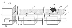
図2は、本実施形態の設備位置特定システムを説明する図である。本設備位置特定システムは、架空ケーブル26の位置を特定する設備位置特定システムであって、
架空ケーブル26に沿う光ファイバ25と、
架空ケーブル26の長手方向の任意箇所で架空ケーブル26を覆う筒状のカバー40と、
光ファイバ25の端部に接続され、カバー40から架空ケーブル26に対して振動が加えられたときの光ファイバ25からの散乱光の時間変化を、光ファイバ25の長手方向の散乱光強度分布の時間変化として取得する光測定器20と、
前記散乱光強度分布に基づいて前記振動が与えられた光ファイバ25上の振動位置を特定し、光ファイバ25上の前記振動位置と架空ケーブル26の地図上の位置とを対応させることで、前記振動が加えられた架空ケーブル26の現実位置を特定する信号処理部21と、
を備える。 (Embodiment 1)
FIG. 2 is a diagram for explaining the equipment position specifying system of this embodiment. This facility position specifying system is a facility position specifying system that specifies the position of the
an
a
It is connected to the end of the
By specifying the vibration position on the
Prepare.
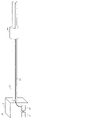
任意箇所で架空ケーブル26を覆う筒41と、
筒41の内壁に設置され、架空ケーブル26と接触し、架空ケーブル26に筒41の振動を伝えるひだ42と、
を備える。 3A and 3B are diagrams illustrating the structure of the
a
a
Prepare.
架空ケーブル26の長手方向の任意箇所で架空ケーブル26を筒状のカバー40で覆うこと(ステップS01)、
架空ケーブル26に含まれる光ファイバ25の端部に光測定器20を接続すること(ステップS02)、
カバー40から架空ケーブル26に対して振動を加えること(ステップS03)、
前記振動が加えられたときの光ファイバ25からの散乱光の時間変化を、光ファイバ25の長手方向の散乱光強度分布の時間変化として取得すること(ステップS04)、
前記散乱光強度分布に基づいて前記振動が与えられた光ファイバ25上の振動位置を特定すること(ステップS05)、及び
光ファイバ25上の前記振動位置と架空ケーブル26の地図50上の位置とを対応させ、前記振動が加えられた架空ケーブル26の現実位置を特定すること(ステップS06)、
を行う。 FIG. 4 is a flow chart for explaining the method for specifying the location of equipment. This facility location identification method is
Covering the
connecting the optical measuring
applying vibration from the
Acquiring the time change of the scattered light from the
Identifying the vibration position on the
I do.
図5のように作業者がカバーに対してハンマーなどで打撃15を加える。例えば、作業者が地上から届く長い棒のハンマーで打撃することが挙げられる。また、作業者がバゲット車でカバー40付近に移動してハンマーで打撃することでもよい。 (Method 1)
As shown in FIG. 5, the operator applies a
図6のように、カバー40は筒41に振動を発生させる振動機構43を備える。振動機構43は、例えば、筒41の中に配置されており、電波で動くピエゾとピエゾに電力を供給する太陽光電池などバッテリーで構成される。カバー40が振動機構43を備える場合、作業者はバゲット車などに乗らずに遠隔で振動付与ができる。 (Method 2)
As shown in FIG. 6, the
一方、カバー40に振動機構43が備わる場合、遠隔操作が可能であり、作業員の作業現地派遣が不要である。ただし、作業時に振動機構43に給電する必要がある場合は、作業員の派遣が必要となる。 FIG. 7 is a table summarizing work styles in step S03. As an operating method, there are cases where the
On the other hand, when the
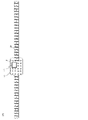
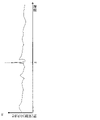
図9のように、光ファイバ25の長手方向距離と敷設されたケーブル26の長さとを対比させることで、信号処理部21は図8の光強度分布のピーク位置(打撃位置52)が地図50上でどの場所にあたるかを判断することができる。 In step S06, the
As shown in FIG. 9, by comparing the longitudinal distance of the
図10は、本実施形態の設備位置特定方法を説明するフローチャートである。図11は、本設備位置特定方法で検査する設備位置特定システムを説明する図である。本設備位置特定方法は、実施形態1の設備位置特定方法に対して、カバー40を取り付けずに設備位置を特定する方法である。本設備位置特定方法は、
架空ケーブル26に含まれる光ファイバ25の端部に光測定器20を接続すること(ステップS02)、
架空ケーブル26を支える任意の柱35に対して振動を加えること(ステップS13)、
前記振動が加えられたときの光ファイバ25からの散乱光の時間変化を、光ファイバ25の長手方向の散乱光強度分布の時間変化として取得すること(ステップS04)、
前記散乱光強度分布に基づいて前記振動が与えられた光ファイバ25上の振動位置を特定すること(ステップS05)、及び
光ファイバ25上の前記振動位置と架空ケーブル26の地図50上の位置とを対応させ、前記振動が加えられた柱35の現実位置を特定すること(ステップS16)、
を行う。 (Embodiment 2)
FIG. 10 is a flow chart for explaining the method of specifying the location of equipment according to this embodiment. FIG. 11 is a diagram for explaining an equipment position identifying system inspected by this equipment position identifying method. This facility position specifying method is a method of specifying the facility position without attaching the
connecting the optical measuring
Applying vibration to any
Acquiring the time change of the scattered light from the
Identifying the vibration position on the
I do.
架空ケーブルに取り付けたカバーあるいは柱に振動を加えて、架空ケーブルに直接衝撃を与えずに振動を付与するため、架空ケーブルにダメージを与えずに散乱光光強度分布を取得することができる。
作業者を派遣した現地で架空ケーブルや電柱の位置及び存在を確定でき、さらに地図と突合が可能である。
カバーを取り付ける方式であれば、電柱のない場所でも架空ケーブルの位置及び存在を確定でき、さらに地図と突合が可能である。
カバーに振動子を付ければ遠隔で架空ケーブルに振動を加えることができる。 [Effect of the invention]
Vibration is applied to the cover or column attached to the aerial cable, and the vibration is applied without directly impacting the aerial cable. Therefore, the scattered light intensity distribution can be obtained without damaging the aerial cable.
The position and existence of overhead cables and utility poles can be determined at the site where workers are dispatched, and furthermore, matching with maps is possible.
If the cover is attached, the position and existence of the aerial cable can be determined even in places where there are no utility poles, and furthermore, matching with the map is possible.
If you attach a vibrator to the cover, you can remotely vibrate the aerial cable.
6:地下
10:通信集約ビル
15:打撃
20:光測定器
21:信号処理部
25:光ファイバ
26:架空ケーブル
30:マンホール
35:柱
40:カバー
41:筒
42:ひだ
43:振動機構
50:地図
51:道路
52:打撃位置 5: Ground 6: Underground 10: Communication aggregation building 15: Impact 20: Optical measuring instrument 21: Signal processing unit 25: Optical fiber 26: Aerial cable 30: Manhole 35: Pillar 40: Cover 41: Tube 42: Folds 43: Vibration Mechanism 50: Map 51: Road 52: Hit location
Claims (7)
- 架空ケーブルの位置を特定する設備位置特定システムであって、
前記架空ケーブルに沿う光ファイバと、
前記架空ケーブルの長手方向の任意箇所で前記架空ケーブルを覆う筒状のカバーと、
前記光ファイバの端部に接続され、前記カバーから前記架空ケーブルに対して振動が加えられたときの前記光ファイバからの散乱光の時間変化を、前記光ファイバの長手方向の散乱光強度分布の時間変化として取得する光測定器と、
前記散乱光強度分布に基づいて前記振動が与えられた前記光ファイバ上の振動位置を特定し、前記光ファイバ上の前記振動位置と前記架空ケーブルの地図上の位置とを対応させることで、前記振動が加えられた前記架空ケーブルの現実位置を特定する信号処理部と、
を備える設備位置特定システム。 A facility location system for locating an overhead cable, comprising:
an optical fiber along the aerial cable;
a cylindrical cover that covers the aerial cable at any position in the longitudinal direction of the aerial cable;
It is connected to the end of the optical fiber, and the time change of the scattered light from the optical fiber when vibration is applied from the cover to the aerial cable is measured as the scattered light intensity distribution in the longitudinal direction of the optical fiber. an optical measuring instrument that acquires as a time change;
By specifying the vibration position on the optical fiber to which the vibration is applied based on the scattered light intensity distribution, and matching the vibration position on the optical fiber with the position on the map of the aerial cable, a signal processing unit that identifies the actual position of the aerial cable to which vibration is applied;
A facility location system comprising: - 前記カバーは、前記振動を加える振動機構を備えることを特徴とする請求項1に記載の設備位置特定システム。 The facility location identification system according to claim 1, wherein the cover includes a vibration mechanism that applies the vibration.
- 前記カバーは、内壁に前記架空ケーブルと接触し、前記架空ケーブルに前記振動を伝えるひだを持つことを特徴とする請求項1又は2に記載の設備位置特定システム。 The equipment location identification system according to claim 1 or 2, wherein the cover has a fold on the inner wall that contacts the aerial cable and transmits the vibration to the aerial cable.
- 振動を発生させる振動機構と、
任意箇所で光ケーブルを含む架空ケーブルを覆い、前記架空ケーブルに前記振動を伝える筒と、
を備えるカバー。 a vibration mechanism that generates vibration;
a tube that covers an aerial cable including an optical cable at an arbitrary location and transmits the vibration to the aerial cable;
A cover with a - 任意箇所で光ケーブルを含む架空ケーブルを覆う筒と、
前記筒の内壁に設置され、前記架空ケーブルと接触し、前記架空ケーブルに前記筒の振動を伝えるひだと、
を備えるカバー。 a tube covering an aerial cable including an optical cable at an arbitrary location;
A fold installed on the inner wall of the tube, in contact with the aerial cable, and transmitting vibration of the tube to the aerial cable;
A cover with a - 架空ケーブルの位置を特定する設備位置特定方法であって、
前記架空ケーブルの長手方向の任意箇所で前記架空ケーブルを筒状のカバーで覆うこと、
前記架空ケーブルに含まれる光ファイバの端部に光測定器を接続すること、
前記カバーから前記架空ケーブルに対して振動を加えること、
前記振動が加えられたときの前記光ファイバからの散乱光の時間変化を、前記光ファイバの長手方向の散乱光強度分布の時間変化として取得すること、
前記散乱光強度分布に基づいて前記振動が与えられた前記光ファイバ上の振動位置を特定すること、及び
前記光ファイバ上の前記振動位置と前記架空ケーブルの地図上の位置とを対応させ、前記振動が加えられた前記架空ケーブルの現実位置を特定すること、
を行う設備位置特定方法。 A facility location identification method for identifying the location of an overhead cable, comprising:
covering the aerial cable with a tubular cover at any position in the longitudinal direction of the aerial cable;
connecting an optical measuring instrument to the end of an optical fiber included in the overhead cable;
applying vibration from the cover to the aerial cable;
Acquiring the time change of the scattered light from the optical fiber when the vibration is applied as the time change of the scattered light intensity distribution in the longitudinal direction of the optical fiber;
identifying a vibration position on the optical fiber to which the vibration is applied based on the scattered light intensity distribution; identifying the actual position of the aerial cable to which the vibration was applied;
equipment location method. - 架空ケーブルを支える柱の位置を特定する設備位置特定方法であって、
前記架空ケーブルに含まれる光ファイバの端部に光測定器を接続すること、
任意の前記柱に対して振動を加えること、
前記振動が加えられたときの前記光ファイバからの散乱光の時間変化を、前記光ファイバの長手方向の散乱光強度分布の時間変化として取得すること、
前記散乱光強度分布に基づいて前記振動が与えられた前記光ファイバ上の振動位置を特定すること、及び
前記光ファイバ上の前記振動位置と前記架空ケーブルの地図上の位置とを対応させ、前記振動が加えられた前記柱の現実位置を特定すること、
を行う設備位置特定方法。 A facility location identifying method for identifying the location of a pillar supporting an overhead cable, comprising:
connecting an optical measuring instrument to the end of an optical fiber included in the overhead cable;
applying vibration to any of the columns;
Acquiring the time change of the scattered light from the optical fiber when the vibration is applied as the time change of the scattered light intensity distribution in the longitudinal direction of the optical fiber;
identifying a vibration position on the optical fiber to which the vibration is applied based on the scattered light intensity distribution; identifying the actual position of the pillar to which the vibration was applied;
equipment location method.
Priority Applications (5)
| Application Number | Priority Date | Filing Date | Title |
|---|---|---|---|
| US18/269,858 US20240060817A1 (en) | 2021-01-21 | 2021-01-21 | Equipment location identification system, cover, and equipment location identification method |
| JP2022576290A JPWO2022157877A1 (en) | 2021-01-21 | 2021-01-21 | |
| PCT/JP2021/002003 WO2022157877A1 (en) | 2021-01-21 | 2021-01-21 | Equipment location specifying system, cover, and equipment location specifying method |
| CN202180081160.1A CN116569002A (en) | 2021-01-21 | 2021-01-21 | Device position determination system, cover, and device position determination method |
| EP21920990.5A EP4283250A1 (en) | 2021-01-21 | 2021-01-21 | Equipment location specifying system, cover, and equipment location specifying method |
Applications Claiming Priority (1)
| Application Number | Priority Date | Filing Date | Title |
|---|---|---|---|
| PCT/JP2021/002003 WO2022157877A1 (en) | 2021-01-21 | 2021-01-21 | Equipment location specifying system, cover, and equipment location specifying method |
Publications (1)
| Publication Number | Publication Date |
|---|---|
| WO2022157877A1 true WO2022157877A1 (en) | 2022-07-28 |
Family
ID=82548548
Family Applications (1)
| Application Number | Title | Priority Date | Filing Date |
|---|---|---|---|
| PCT/JP2021/002003 WO2022157877A1 (en) | 2021-01-21 | 2021-01-21 | Equipment location specifying system, cover, and equipment location specifying method |
Country Status (5)
| Country | Link |
|---|---|
| US (1) | US20240060817A1 (en) |
| EP (1) | EP4283250A1 (en) |
| JP (1) | JPWO2022157877A1 (en) |
| CN (1) | CN116569002A (en) |
| WO (1) | WO2022157877A1 (en) |
Citations (5)
| Publication number | Priority date | Publication date | Assignee | Title |
|---|---|---|---|---|
| JPH10177055A (en) * | 1996-12-17 | 1998-06-30 | Chubu Electric Power Co Inc | Accident-detected position location system for overhead power transmission line |
| JP2017219369A (en) * | 2016-06-06 | 2017-12-14 | 西松建設株式会社 | Vibration device, vibration measurement system, vibration measurement method, and measurement method of tensile force |
| WO2020044648A1 (en) * | 2018-08-30 | 2020-03-05 | 日本電気株式会社 | Utility-pole position identification system, utility-pole position identification device, utility-pole position identification method, and non-transitory computer readable medium |
| JP2020052030A (en) | 2018-09-20 | 2020-04-02 | 日本電信電話株式会社 | Manhole position specifying method and manhole position specifying system |
| JP2020127094A (en) | 2019-02-01 | 2020-08-20 | 日本電信電話株式会社 | Method of searching optical fiber route, optical fiber route search device and program |
-
2021
- 2021-01-21 EP EP21920990.5A patent/EP4283250A1/en active Pending
- 2021-01-21 CN CN202180081160.1A patent/CN116569002A/en active Pending
- 2021-01-21 WO PCT/JP2021/002003 patent/WO2022157877A1/en active Application Filing
- 2021-01-21 JP JP2022576290A patent/JPWO2022157877A1/ja active Pending
- 2021-01-21 US US18/269,858 patent/US20240060817A1/en active Pending
Patent Citations (5)
| Publication number | Priority date | Publication date | Assignee | Title |
|---|---|---|---|---|
| JPH10177055A (en) * | 1996-12-17 | 1998-06-30 | Chubu Electric Power Co Inc | Accident-detected position location system for overhead power transmission line |
| JP2017219369A (en) * | 2016-06-06 | 2017-12-14 | 西松建設株式会社 | Vibration device, vibration measurement system, vibration measurement method, and measurement method of tensile force |
| WO2020044648A1 (en) * | 2018-08-30 | 2020-03-05 | 日本電気株式会社 | Utility-pole position identification system, utility-pole position identification device, utility-pole position identification method, and non-transitory computer readable medium |
| JP2020052030A (en) | 2018-09-20 | 2020-04-02 | 日本電信電話株式会社 | Manhole position specifying method and manhole position specifying system |
| JP2020127094A (en) | 2019-02-01 | 2020-08-20 | 日本電信電話株式会社 | Method of searching optical fiber route, optical fiber route search device and program |
Also Published As
| Publication number | Publication date |
|---|---|
| JPWO2022157877A1 (en) | 2022-07-28 |
| CN116569002A (en) | 2023-08-08 |
| EP4283250A1 (en) | 2023-11-29 |
| US20240060817A1 (en) | 2024-02-22 |
Similar Documents
| Publication | Publication Date | Title |
|---|---|---|
| US11366231B2 (en) | Smart optical cable positioning/location using optical fiber sensing | |
| JP6974747B2 (en) | Manhole position identification method and manhole position identification system | |
| JP7124875B2 (en) | Utility pole location identification system, utility pole location identification device, utility pole location identification method, and program | |
| WO2020059640A1 (en) | Manhole position specification method and manhole position specification system | |
| CN103673791B (en) | A kind of check and evaluation system for the damage of target high-speed impact | |
| JP5683007B2 (en) | Flaw detection apparatus and flaw detection method | |
| CN105974465A (en) | Tunnel three-dimensional seismic wave advanced detection space observation system and tunnel three-dimensional seismic wave advanced detection space observation method | |
| JP2005321376A (en) | Elastic wave sensing device | |
| WO1993003400A1 (en) | Method of probing optical transmission line | |
| JP2019211349A (en) | Optical fiber route search method, optical fiber route search system, signal processing device, and program | |
| CN103048592A (en) | Method and system for off-line locating power cable fault | |
| WO2022157877A1 (en) | Equipment location specifying system, cover, and equipment location specifying method | |
| CN103837790B (en) | A kind of multicore cable school line apparatus and school line method thereof | |
| CN205966442U (en) | A vibration source for demarcating optic fibre vibration intrusion detection system | |
| JP2011021974A (en) | System and method for detecting damage of concrete pole using natural vibration mode | |
| JP2001221664A (en) | Underground optical fiber sensor and optical fiber sensor system thereof | |
| JP2022126368A (en) | Facility position specification device and facility position specification system | |
| US7579962B1 (en) | Duct mapping device using sonde | |
| KR100325373B1 (en) | Device and Method to Measure Stress Waves inside a Core Hole of Tunnel Lining | |
| CN206038147U (en) | Calibration arrangement for be used for distributed location type optic fibre vibration host computer | |
| CN105547457A (en) | Calibration system used for distributed positioning-type optical fiber vibration host and calibration method thereof | |
| CN111679313A (en) | Method for confirming power optical cable routing by mechanical periodic vibration excitation | |
| KR101953022B1 (en) | Location detecting sonde for sewer facility | |
| JP6504964B2 (en) | Member condition evaluation device and condition evaluation method | |
| JP3575008B2 (en) | Concrete condition measuring device |
Legal Events
| Date | Code | Title | Description |
|---|---|---|---|
| 121 | Ep: the epo has been informed by wipo that ep was designated in this application |
Ref document number: 21920990 Country of ref document: EP Kind code of ref document: A1 |
|
| ENP | Entry into the national phase |
Ref document number: 2022576290 Country of ref document: JP Kind code of ref document: A |
|
| WWE | Wipo information: entry into national phase |
Ref document number: 202180081160.1 Country of ref document: CN |
|
| WWE | Wipo information: entry into national phase |
Ref document number: 18269858 Country of ref document: US |
|
| NENP | Non-entry into the national phase |
Ref country code: DE |
|
| ENP | Entry into the national phase |
Ref document number: 2021920990 Country of ref document: EP Effective date: 20230821 |