WO2022149540A1 - ガスタービン燃焼器及びガスタービン - Google Patents
ガスタービン燃焼器及びガスタービン Download PDFInfo
- Publication number
- WO2022149540A1 WO2022149540A1 PCT/JP2021/048742 JP2021048742W WO2022149540A1 WO 2022149540 A1 WO2022149540 A1 WO 2022149540A1 JP 2021048742 W JP2021048742 W JP 2021048742W WO 2022149540 A1 WO2022149540 A1 WO 2022149540A1
- Authority
- WO
- WIPO (PCT)
- Prior art keywords
- fuel
- gas turbine
- fuel injector
- ratio
- value
- Prior art date
Links
- 239000000446 fuel Substances 0.000 claims abstract description 394
- 238000002485 combustion reaction Methods 0.000 claims abstract description 89
- 239000007789 gas Substances 0.000 claims description 156
- 239000000567 combustion gas Substances 0.000 claims description 44
- ATUOYWHBWRKTHZ-UHFFFAOYSA-N Propane Chemical compound CCC ATUOYWHBWRKTHZ-UHFFFAOYSA-N 0.000 claims description 20
- 239000001257 hydrogen Substances 0.000 claims description 18
- 229910052739 hydrogen Inorganic materials 0.000 claims description 18
- VNWKTOKETHGBQD-UHFFFAOYSA-N methane Chemical compound C VNWKTOKETHGBQD-UHFFFAOYSA-N 0.000 claims description 14
- 150000002431 hydrogen Chemical class 0.000 claims description 10
- 239000001294 propane Substances 0.000 claims description 10
- UFHFLCQGNIYNRP-UHFFFAOYSA-N Hydrogen Chemical compound [H][H] UFHFLCQGNIYNRP-UHFFFAOYSA-N 0.000 claims description 8
- 238000009792 diffusion process Methods 0.000 claims description 8
- 239000003345 natural gas Substances 0.000 claims description 7
- 239000000203 mixture Substances 0.000 claims description 6
- 206010016754 Flashback Diseases 0.000 description 43
- 238000011144 upstream manufacturing Methods 0.000 description 9
- 238000010586 diagram Methods 0.000 description 8
- 230000007613 environmental effect Effects 0.000 description 8
- 230000006870 function Effects 0.000 description 7
- 230000002093 peripheral effect Effects 0.000 description 7
- 230000014509 gene expression Effects 0.000 description 5
- 238000002347 injection Methods 0.000 description 5
- 239000007924 injection Substances 0.000 description 5
- 238000010248 power generation Methods 0.000 description 5
- 238000004364 calculation method Methods 0.000 description 3
- UGFAIRIUMAVXCW-UHFFFAOYSA-N Carbon monoxide Chemical compound [O+]#[C-] UGFAIRIUMAVXCW-UHFFFAOYSA-N 0.000 description 2
- 229910002091 carbon monoxide Inorganic materials 0.000 description 2
- 238000010344 co-firing Methods 0.000 description 2
- 239000002737 fuel gas Substances 0.000 description 2
- 229930195733 hydrocarbon Natural products 0.000 description 2
- 150000002430 hydrocarbons Chemical class 0.000 description 2
- 239000000126 substance Substances 0.000 description 2
- 238000004590 computer program Methods 0.000 description 1
- 230000006866 deterioration Effects 0.000 description 1
- 238000006073 displacement reaction Methods 0.000 description 1
- 230000000694 effects Effects 0.000 description 1
- 238000000605 extraction Methods 0.000 description 1
- 239000012530 fluid Substances 0.000 description 1
- 239000000463 material Substances 0.000 description 1
- 239000007800 oxidant agent Substances 0.000 description 1
Images


Classifications
-
- F—MECHANICAL ENGINEERING; LIGHTING; HEATING; WEAPONS; BLASTING
- F23—COMBUSTION APPARATUS; COMBUSTION PROCESSES
- F23R—GENERATING COMBUSTION PRODUCTS OF HIGH PRESSURE OR HIGH VELOCITY, e.g. GAS-TURBINE COMBUSTION CHAMBERS
- F23R3/00—Continuous combustion chambers using liquid or gaseous fuel
- F23R3/28—Continuous combustion chambers using liquid or gaseous fuel characterised by the fuel supply
- F23R3/36—Supply of different fuels
-
- F—MECHANICAL ENGINEERING; LIGHTING; HEATING; WEAPONS; BLASTING
- F02—COMBUSTION ENGINES; HOT-GAS OR COMBUSTION-PRODUCT ENGINE PLANTS
- F02C—GAS-TURBINE PLANTS; AIR INTAKES FOR JET-PROPULSION PLANTS; CONTROLLING FUEL SUPPLY IN AIR-BREATHING JET-PROPULSION PLANTS
- F02C7/00—Features, components parts, details or accessories, not provided for in, or of interest apart form groups F02C1/00 - F02C6/00; Air intakes for jet-propulsion plants
- F02C7/22—Fuel supply systems
- F02C7/222—Fuel flow conduits, e.g. manifolds
-
- F—MECHANICAL ENGINEERING; LIGHTING; HEATING; WEAPONS; BLASTING
- F02—COMBUSTION ENGINES; HOT-GAS OR COMBUSTION-PRODUCT ENGINE PLANTS
- F02C—GAS-TURBINE PLANTS; AIR INTAKES FOR JET-PROPULSION PLANTS; CONTROLLING FUEL SUPPLY IN AIR-BREATHING JET-PROPULSION PLANTS
- F02C9/00—Controlling gas-turbine plants; Controlling fuel supply in air- breathing jet-propulsion plants
- F02C9/26—Control of fuel supply
- F02C9/40—Control of fuel supply specially adapted to the use of a special fuel or a plurality of fuels
-
- F—MECHANICAL ENGINEERING; LIGHTING; HEATING; WEAPONS; BLASTING
- F23—COMBUSTION APPARATUS; COMBUSTION PROCESSES
- F23R—GENERATING COMBUSTION PRODUCTS OF HIGH PRESSURE OR HIGH VELOCITY, e.g. GAS-TURBINE COMBUSTION CHAMBERS
- F23R3/00—Continuous combustion chambers using liquid or gaseous fuel
- F23R3/02—Continuous combustion chambers using liquid or gaseous fuel characterised by the air-flow or gas-flow configuration
- F23R3/26—Controlling the air flow
-
- F—MECHANICAL ENGINEERING; LIGHTING; HEATING; WEAPONS; BLASTING
- F05—INDEXING SCHEMES RELATING TO ENGINES OR PUMPS IN VARIOUS SUBCLASSES OF CLASSES F01-F04
- F05D—INDEXING SCHEME FOR ASPECTS RELATING TO NON-POSITIVE-DISPLACEMENT MACHINES OR ENGINES, GAS-TURBINES OR JET-PROPULSION PLANTS
- F05D2220/00—Application
- F05D2220/30—Application in turbines
- F05D2220/32—Application in turbines in gas turbines
-
- F—MECHANICAL ENGINEERING; LIGHTING; HEATING; WEAPONS; BLASTING
- F05—INDEXING SCHEMES RELATING TO ENGINES OR PUMPS IN VARIOUS SUBCLASSES OF CLASSES F01-F04
- F05D—INDEXING SCHEME FOR ASPECTS RELATING TO NON-POSITIVE-DISPLACEMENT MACHINES OR ENGINES, GAS-TURBINES OR JET-PROPULSION PLANTS
- F05D2220/00—Application
- F05D2220/70—Application in combination with
- F05D2220/75—Application in combination with equipment using fuel having a low calorific value, e.g. low BTU fuel, waste end, syngas, biomass fuel or flare gas
-
- F—MECHANICAL ENGINEERING; LIGHTING; HEATING; WEAPONS; BLASTING
- F05—INDEXING SCHEMES RELATING TO ENGINES OR PUMPS IN VARIOUS SUBCLASSES OF CLASSES F01-F04
- F05D—INDEXING SCHEME FOR ASPECTS RELATING TO NON-POSITIVE-DISPLACEMENT MACHINES OR ENGINES, GAS-TURBINES OR JET-PROPULSION PLANTS
- F05D2240/00—Components
- F05D2240/35—Combustors or associated equipment
-
- F—MECHANICAL ENGINEERING; LIGHTING; HEATING; WEAPONS; BLASTING
- F05—INDEXING SCHEMES RELATING TO ENGINES OR PUMPS IN VARIOUS SUBCLASSES OF CLASSES F01-F04
- F05D—INDEXING SCHEME FOR ASPECTS RELATING TO NON-POSITIVE-DISPLACEMENT MACHINES OR ENGINES, GAS-TURBINES OR JET-PROPULSION PLANTS
- F05D2270/00—Control
- F05D2270/30—Control parameters, e.g. input parameters
- F05D2270/303—Temperature
-
- F—MECHANICAL ENGINEERING; LIGHTING; HEATING; WEAPONS; BLASTING
- F23—COMBUSTION APPARATUS; COMBUSTION PROCESSES
- F23R—GENERATING COMBUSTION PRODUCTS OF HIGH PRESSURE OR HIGH VELOCITY, e.g. GAS-TURBINE COMBUSTION CHAMBERS
- F23R2900/00—Special features of, or arrangements for continuous combustion chambers; Combustion processes therefor
- F23R2900/00002—Gas turbine combustors adapted for fuels having low heating value [LHV]
Definitions
- the operation state may be switched to turndown operation in order to respond to fluctuations in power demand during the day and at night.
- the flow rate of the combustion gas passing through the turbine is reduced to operate the gas turbine at a lower output than in the rated operation (see, for example, Patent Document 1).
- At least one embodiment of the present disclosure aims to achieve both a reduction in the lower limit of output in turndown operation and a reduction in the risk of flashback in view of the above circumstances.
- the gas turbine combustor is The first fuel injector and With the second fuel injector, A combustion unit in which the fuel injected from the first fuel injector and the second fuel injector burns, A low-combustible fuel flow rate adjusting unit for independently adjusting the supply amount of low-combustible fuel to the first fuel injector and the second fuel injector, A high combustible fuel flow rate adjusting unit for independently adjusting the supply amounts of high combustible fuel having a higher combustion speed than the low combustible fuel to the first fuel injector and the second fuel injector.
- a controller configured to control the low combustible fuel flow rate adjusting unit and the high combustible fuel flow rate adjusting unit so that the relative ratio of the second ratio of the high combustible fuel to the above changes.
- the gas turbine according to at least one embodiment of the present disclosure includes a gas turbine combustor having the configuration of (1) above.
- FIG. 1 It is a schematic block diagram which shows the gas turbine which concerns on some Embodiments. It is sectional drawing which shows the combustor which concerns on some Embodiments. It is sectional drawing which shows the main part of the combustor which concerns on some Embodiments. It is a figure which showed schematically the arrangement of each fuel injector when the combustor which concerns on some embodiments is seen from the downstream side to the upstream side along the axis direction of a combustor. It is a figure which showed schematically the arrangement of each fuel injector when the combustor which concerns on another embodiment is seen from the downstream side to the upstream side along the axis direction of a combustor.
- expressions such as “same”, “equal”, and “homogeneous” that indicate that things are in the same state not only represent exactly the same state, but also have tolerances or differences to the extent that the same function can be obtained. It shall also represent the existing state.
- an expression representing a shape such as a square shape or a cylindrical shape not only represents a shape such as a square shape or a cylindrical shape in a geometrically strict sense, but also an uneven portion or a chamfering within a range where the same effect can be obtained. It shall also represent the shape including the part and the like.
- the expressions “equipped”, “equipped”, “equipped”, “included”, or “have” one component are not exclusive expressions excluding the existence of other components.
- FIG. 1 is a schematic configuration diagram showing a gas turbine 1 according to some embodiments.
- a gas turbine which is an example of the application destination of the gas turbine combustor according to some embodiments, will be described with reference to FIG.
- the gas turbine 1 has a compressor 2 for generating compressed air as an oxidizing agent and a gas for generating combustion gas using compressed air and fuel. It includes a turbine compressor 4 and a turbine 6 configured to be rotationally driven by combustion gas.
- a generator (not shown) is connected to the turbine 6, and power is generated by the rotational energy of the turbine 6.
- the gas turbine combustor 4 is also simply referred to as a combustor 4.
- the compressor 2 is provided on the inlet side of the compressor vehicle compartment 10 and the compressor vehicle compartment 10, and has an air intake port 12 for taking in air, the compressor vehicle compartment 10, and the turbine vehicle compartment described later. It includes a rotor 8 provided so as to penetrate the 22 together, and various blades arranged in the compressor casing 10.
- the various blades are a rotor so as to be alternately arranged with respect to the inlet guide blade 14 provided on the air intake inlet 12, the plurality of stationary blades 16 fixed to the compressor casing 10 side, and the stationary blade 16. Includes a plurality of blades 18 planted in 8.
- the compressor 2 may include other components such as an air extraction chamber (not shown).
- the air taken in from the air intake port 12 passes through the plurality of stationary blades 16 and the plurality of moving blades 18 and is compressed to become high-temperature and high-pressure compressed air. Then, the high-temperature and high-pressure compressed air is sent from the compressor 2 to the combustor 4 in the subsequent stage.
- the combustor 4 is arranged in the casing 20. As shown in FIG. 1, a plurality of combustors 4 may be arranged in a ring around the rotor 8 in the casing 20. Fuel and compressed air generated by the compressor 2 are supplied to the combustor 4, and by burning the fuel, combustion gas, which is the working fluid of the turbine 6, is generated. Then, the combustion gas is sent from the combustor 4 to the turbine 6 in the subsequent stage. A configuration example of the combustor 4 according to some embodiments will be described later.
- the turbine 6 includes a turbine casing 22 and various blades arranged in the turbine casing 22.
- the various blades include a plurality of stationary blades 24 fixed to the turbine casing 22 side and a plurality of rotor blades 26 planted in the rotor 8 so as to be alternately arranged with respect to the stationary blades 24. ..
- the turbine 6 may include other components such as an outlet guide blade.
- the rotor 8 is rotationally driven by the combustion gas passing through the plurality of stationary blades 24 and the plurality of moving blades 26. As a result, the generator connected to the rotor 8 is driven.
- An exhaust chamber 30 is connected to the downstream side of the turbine casing 22 via an exhaust casing 28. The combustion gas after driving the turbine 6 is discharged to the outside through the exhaust chamber 28 and the exhaust chamber 30.
- FIG. 2 is a cross-sectional view showing the combustor 4 according to some embodiments.
- FIG. 3 is a cross-sectional view showing a main part of the combustor 4 according to some embodiments.
- FIG. 4A is a diagram schematically showing the arrangement of each fuel injector when the combustor 4 according to some embodiments is viewed from the downstream side to the upstream side along the axial direction of the combustor 4. The configuration of the combustor 4 according to some embodiments will be described with reference to FIGS. 2, 3 and 4A.
- a plurality of combustors 4 are arranged in an annular shape around the rotor 8 (see FIG. 1).
- Each combustor 4 has a combustor liner 46 provided in a combustor casing 40 defined by a casing 20, and a first fuel injector 41 and a second fuel injector 42 arranged in the combustor liner 46, respectively.
- the first fuel injector 41 may be the main combustion burner 60 and the second fuel injector 42 may be the pilot combustion burner 50.
- the fuel F injected from the first fuel injector 41 is also referred to as a first fuel F1
- the fuel F injected from the second fuel injector 42 is also referred to as a second fuel F2.
- the combustor 4 further includes an outer cylinder 45 provided on the outer peripheral side of the inner cylinder 47 of the combustor liner 46 inside the casing 20.
- An air passage 43 through which compressed air flows is formed on the outer peripheral side of the inner cylinder 47 and the inner peripheral side of the outer cylinder 45.
- the combustor 4 may include other components such as a bypass pipe (not shown) for bypassing the combustion gas.
- the combustor liner 46 has an inner cylinder 47 arranged around a pilot combustion burner 50 and a plurality of main combustion burners 60, and a tail cylinder 48 connected to a tip end portion of the inner cylinder 47. .. That is, the combustor liner 46 corresponds to a combustion portion where the fuel F injected from the first fuel injector 41 and the second fuel injector 42 burns.
- the pilot combustion burner 50 is arranged along the central axis of the combustor liner 46.
- a plurality of main combustion burners 60 are arranged side by side in the circumferential direction so as to surround the outer peripheral side of the pilot combustion burner 50 so as to be separated from each other.
- the pilot combustion burner 50 is provided on the outer periphery of the pilot nozzle (nozzle) 54 connected to the fuel port 52, the pilot burner cylinder 56 arranged so as to surround the pilot nozzle 54, and the pilot nozzle 54. It has a plurality of swirls (swivel plates) 58 provided.
- the pilot nozzle 54 extends in the axial direction Da about the combustor axis Ac.
- the upstream side on one side of the axis direction Da which is the extending direction of the combustor axis Ac, along the flow of the combustion gas is the upstream side, and the other side is the downstream side along the flow of the combustion gas. Is the downstream side.
- the combustor axis Ac is also the burner axis of the pilot combustion burner 50.
- An injection hole (not shown) for injecting fuel F (second fuel F2) is formed at the downstream end of the pilot nozzle 54.
- a plurality of swivel plates 58 are provided on the upstream side of the position where the injection hole is formed by the pilot nozzle 54.
- Each swivel plate 58 is for swirling compressed air around the combustor axis Ac.
- Each swivel plate 58 extends from the outer periphery of the pilot nozzle 54 in a direction including a radial component, and is close to the inner peripheral surface of the pilot burner cylinder 56.
- the pilot burner cylinder 56 has a main body portion 56a located on the outer periphery of the pilot nozzle 54, and a cone portion 56b connected to the downstream side of the main body portion 56a and gradually increasing in diameter toward the downstream side.
- the plurality of swivel plates 58 are close to the inner peripheral surface of the main body portion 56a of the pilot burner cylinder 56.
- the main combustion burner 60 includes a main nozzle (nozzle) 64 connected to the fuel port 62, a main burner cylinder 66 arranged so as to surround the main nozzle 64, a main burner cylinder 66, and a combustor liner 46 (for example, an inner cylinder). It has an extension pipe 65 for connecting 47) and a swirl (swivel plate) 70 provided on the outer periphery of the main nozzle 64.
- the main nozzle 64 is a rod-shaped nozzle extending in the axial direction Da around the burner axis Ab parallel to the combustor axis Ac. Since the burner axis Ab of the main combustion burner 60 is parallel to the combustor axis Ac, the axis direction Da with respect to the combustor axis Ac and the axis direction Da with respect to the burner axis Ab are the same directions. Further, the upstream side of the axial direction Da with respect to the combustor axis Ac is the upstream side of the axial direction Da with respect to the burner axis Ab, and the downstream side of the axial direction Da with respect to the combustor axis Ac is the downstream side of the axial direction Da with respect to the burner axis Ab. On the side.
- An injection hole for injecting fuel F (first fuel F1) is formed in the middle portion of the main nozzle 64 in the axial direction Da.
- a plurality of swivel plates 70 are provided in the vicinity of the position where the injection hole is formed in the main nozzle 64.
- Each swivel plate 70 is for swirling compressed air around the burner axis Ab.
- Each swivel plate 70 extends from the outer periphery of the main nozzle 64 in a direction including a radial component, and is close to the inner peripheral surface of the main burner cylinder 66.
- the main burner cylinder 66 is located on the outer periphery of the main nozzle 64.
- the compressed air generated by the compressor 2 is supplied into the combustor cabin 40 from the cabin inlet 40a, and further from the combustor casing 40 via the air passage 43 to the pilot burner. It flows into the cylinder 56 and the plurality of main burner cylinders 66.
- the fuel F injected from the pilot nozzle 54 is ejected together with the compressed air from the downstream end of the pilot burner cylinder 56.
- This fuel F is diffusely combusted in the combustor liner 46. That is, the pilot combustion burner 50 (second fuel injector 42) shown in FIGS. 2, 3 and 4A is a diffusion combustion type fuel injector.
- the compressed air and the fuel F injected from the main nozzle 64 are mixed in the main burner cylinder 66 to form a premixed gas PM.
- the premixed gas PM is ejected from the downstream end of the extension pipe 65.
- the fuel F in the premixed gas PM is premixed and combusted in the combustor liner 46. That is, the main combustion burner 60 (first fuel injector 41) shown in FIGS. 2, 3 and 4A is a premixed combustion type fuel injector.
- the portion corresponding to the rod-shaped main nozzle 64 described above forms a hub rod, and the main nozzle is formed by having the hub rod and the plurality of swivel plates 70. Fuel F from the outside is supplied to the inside of the hub rod, and fuel F is supplied to the swivel plate 70 from the hub rod.
- FIG. 4B is a diagram schematically showing the arrangement of the fuel injectors 41 and 42 when the combustor 4 according to another embodiment is viewed from the downstream side to the upstream side along the axial direction of the combustor 4. be.
- the first fuel injector 41 is arranged coaxially with the second fuel injector 42.
- the combustor 4 shown in FIG. 4B is configured to inject the first fuel F1 from the periphery of the second fuel injector 42.
- the first fuel injector 41 and the second fuel injector 42 are arranged side by side in the circumferential direction in the inner cylinder 47.
- the first fuel injector 41 and the second fuel injector 42 may both be premixed combustion type fuel injectors.
- the operation state may be switched to turndown operation in order to respond to fluctuations in power demand during the day and at night.
- the flow rate of the combustion gas passing through the turbine is reduced to operate the gas turbine with a lower output than in the rated operation.
- the combustion temperature in the combustor is lowered, and as a result, the amount of unburned substances such as carbon monoxide and hydrocarbons is increased, and combustion vibration is caused. It will cause an outbreak.
- natural gas is used as the fuel F, for example, as in the conventional combustor, and hydrogen, propane, or a mixture of hydrogen and propane is used as the highly combustible fuel FH. It is configured so that either one can be used.
- hydrogen is used as a highly combustible fuel
- natural gas which is a conventionally used fuel F
- FL low-combustibility fuel FL. That is, the highly combustible fuel FH is a fuel having a higher combustion rate than the low combustible fuel FL.
- the combustion rate of the fuel F referred to here is, for example, the combustion rate of the air-fuel mixture in which the fuel F and air are mixed so that the equivalent ratio becomes 1 in the standard state (0 ° C., 1013 hPa).
- natural gas as the low-combustible fuel FL
- hydrogen, propane, or a mixture of hydrogen and propane as the high-combustible fuel FH
- FIG. 5 is a diagram showing an outline of the fuel F supply system 200 for the combustor 4 according to some embodiments.
- the gas turbine 1 includes the fuel F supply system 200 shown in FIG.
- the fuel F supply system 200 shown in FIG. 5 supplies the L1 supply line 211 for supplying the low combustible fuel FL to the first fuel injector 41 and the low combustible fuel FL to the second fuel injector 42.
- L2 supply line 212 for supplying the highly combustible fuel FH to the first fuel injector 41
- H1 supply line 221 for supplying the highly combustible fuel FH to the second fuel injector 42. Includes line 222.
- the L1 supply line 211 and the H1 supply line 221 are merged at the confluence section 231.
- the fuel supply line after the merging portion 231 is referred to as a first fuel supply line 201.
- the first fuel supply line 201 is connected to the fuel port 62 to which the main nozzle 64 of the main combustion burner 60 (first fuel injector 41) is connected.
- the L2 supply line 212 and the H2 supply line 222 are merged at the confluence portion 232.
- the fuel supply line after the confluence 232 is referred to as a second fuel supply line 202.
- the second fuel supply line 202 is connected to the fuel port 52 to which the pilot nozzle 44 of the pilot combustion burner 50 (second fuel injector 42) is connected.
- the L1 supply line 211 is provided with an L1 flow rate adjusting unit 241 for adjusting the supply amount of the low combustible fuel FL to the first fuel injector 41.
- the L2 supply line 212 is provided with an L2 flow rate adjusting unit 242 for adjusting the supply amount of the low combustible fuel FL to the second fuel injector 42.
- the H1 supply line 221 is provided with an H1 flow rate adjusting unit 243 for adjusting the supply amount of the highly combustible fuel FH to the first fuel injector 41.
- the H2 supply line 222 is provided with an H2 flow rate adjusting unit 244 for adjusting the supply amount of the highly combustible fuel FH to the second fuel injector 42.
- the L1 flow rate adjusting unit 241, the L2 flow rate adjusting unit 242, the H1 flow rate adjusting unit 243, and the H2 flow rate adjusting unit 244 are, for example, flow rate adjusting valves.
- 240L includes an L1 flow rate adjusting unit 241 and an L2 flow rate adjusting unit 242.
- a highly combustible fuel flow rate adjusting unit for adjusting the supply amount of the highly combustible fuel FH to the first fuel injector 41 and the second fuel injector 42 independently of each other.
- 240H includes an H1 flow rate adjusting unit 243 and an H2 flow rate adjusting unit 244.
- the L1 flow rate adjusting unit 241, the L2 flow rate adjusting unit 242, the H1 flow rate adjusting unit 243, and the H2 flow rate adjusting unit 244 are configured to control the low combustible fuel flow rate adjusting unit 240L and the high combustible fuel flow rate adjusting unit 240H. It is controlled by the controller.
- the controller is implemented by the combustion control device 140 of the gas turbine 1. That is, in some embodiments, the first ratio R1 of the highly combustible fuel FH to the entire first fuel F1 injected by the first fuel injector 41 and the second injected by the second fuel injector 42. The second ratio R2 of the highly combustible fuel FH to the entire fuel F2 is controlled by the combustion control device 140. Details of the combustion control device 140 will be described later.
- a highly combustible fuel FH having a relatively high combustion rate such as hydrogen can be co-combusted, so that the lower limit of output in the turndown operation of the gas turbine 1 is reduced. be able to.
- the risk of flashback increases. That is, there is a trade-off relationship between reducing the lower limit of output in turndown operation and reducing the risk of flashback.
- the risk of flashback differs depending on the structure of the fuel injector, the arrangement position of the fuel injector, and the like, the risk of flashback is not always the same for all fuel injectors in a plurality of fuel injectors. Specifically, for example, it is as follows.
- the first fuel injector 41 is a premixed combustion type fuel injector
- the second fuel injector 42 is a diffusion combustion type fuel injector. ..
- a diffusion combustion type fuel injector is a combustor having a lower risk of flashback than a premixed combustion type fuel injector. Therefore, in the embodiment shown in FIGS. 2, 3 and 4A, the second fuel injector 42 is a combustor having a smaller risk of flashback than the first fuel injector 41.
- the surrounding fuel injector is more flashback than the surrounding fuel injector.
- the risk is smaller.
- a plurality of first fuel injectors 41 are arranged around the second fuel injector 42. Therefore, as in the case where the first fuel injector 41 and the second fuel injector 42 are both diffusion combustion type or premixed combustion type fuel injectors in the embodiment shown in FIGS. 2, 3 and 4A. If the structure of the fuel injector is the same for the first fuel injector 41 and the second fuel injector 42, the second fuel injector is a combustor having a smaller risk of flashback than the first fuel injector. Become.
- the first fuel injector 41 is arranged coaxially with the second fuel injector 42, and is configured to inject the first fuel F1 from the periphery of the second fuel injector 42. ing.
- one fuel injector is placed coaxially with the other fuel injector, and each fuel injector is configured such that one fuel injector injects fuel from around the other fuel injector. If so, the other fuel injector has a lower risk of flashback than the one fuel injector. Therefore, as in the case where the first fuel injector 41 and the second fuel injector 42 are both diffusion combustion type or premixed combustion type fuel injectors in the embodiment shown in FIG. 4B, the first fuel injector If the structure of the fuel injector is the same for the 41 and the second fuel injector 42, the second fuel injector 42 is a combustor having a smaller risk of flashback than the first fuel injector 41.
- the lower limit of the output in the turndown operation is reduced by changing the relative ratio R between the first ratio R1 and the second ratio R2 in consideration of these. And to reduce the risk of flashback. That is, in the combustor 4 according to some embodiments, the combustion control device 140 has low combustion so that the relative ratio R of the first ratio R1 and the second ratio R2 changes according to the operating state of the gas turbine 1. It is configured to control the sex fuel flow rate adjusting unit 240L and the highly combustible fuel flow rate adjusting unit 240H.
- the relative lower limit value in the turndown operation is reduced and the risk of flashback is reduced by changing the relative ratio R according to the operating state of the gas turbine 1. It is possible to achieve both.
- the gas turbine 1 provided with the combustor 4 according to some embodiments it is possible to achieve both a reduction in the lower limit of the output in the turndown operation and a reduction in the risk of flashback, and the operation of the gas turbine 1 can be achieved. You can spread the band.
- the change of the relative ratio R according to the operating state of the gas turbine 1 will be described in detail.
- the risk of flashback differs depending on the structure of the fuel injector, the position of the fuel injector, etc., so that the risk of flashback is the same for all fuel injectors in a plurality of fuel injectors. Is not always.
- the first fuel injector 41 is a combustor having a higher risk of flashback than the second fuel injector 42, the higher the load of the gas turbine, the greater the degree of reduction of the second ratio R2. It is also desirable to increase the degree of reduction of the first ratio R1. That is, the higher the load of the gas turbine 1, the smaller the value obtained by dividing the first ratio R1 by the second ratio R2 (the lower the load of the gas turbine 1, the smaller the first ratio R1 and the second ratio R2). It is desirable to increase the value divided by).
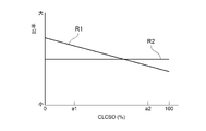
- FIG. 6A is a graph showing an example of the relationship between the first ratio R1 and the second ratio R2 and the index representing the operating state of the gas turbine 1.
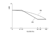
- FIG. 6B is a graph showing another example of the relationship between the first ratio R1 and the second ratio R2 and the index representing the operating state of the gas turbine 1.
- 6C and 6D are graphs showing other examples of the relationship between the first ratio R1 and the index representing the operating state of the gas turbine 1.
- FIG. 6E is a graph showing another example of the relationship between the second ratio R2 and the index representing the operating state of the gas turbine 1.
- a combustion load command value (a non-dimensional value obtained by making the gas turbine inlet combustion gas temperature T1T and the gas turbine inlet combustion gas temperature T1T non-dimensional) ( CLCSO)
- the load of the gas turbine 1 (generator output: gas turbine output) can be mentioned.
- the gas turbine inlet combustion gas temperature T1T is the temperature of the combustion gas at the inlet of the turbine 6.
- CLCSO will be described in detail later.
- the load of the gas turbine 1 may be a measured value of the generator output, or is a generator output command value sent from a central power supply center (not shown) that manages the generator outputs of a plurality of power generation facilities. May be good.
- the index may be the gas turbine inlet combustion gas temperature T1T.
- the gas turbine inlet combustion gas temperature T1T is an index that more accurately indicates the operating state of the gas turbine 1 as compared with, for example, the load of the gas turbine 1. If the index is the gas turbine inlet combustion gas temperature T1T, the relative ratio R can be more accurately reflected in the operating state of the gas turbine 1, so that the control accuracy of the relative ratio R can be improved. ..
- the indicator may be a dimensionless value (CLCSO) of the gas turbine inlet combustion gas temperature T1T.
- CLCSO dimensionless value
- the gas turbine inlet combustion gas temperature T1T is an index that more accurately indicates the operating state of the gas turbine 1 as compared with the load of the gas turbine 1, for example.
- the gas turbine inlet combustion gas temperature T1T has become high, and it is difficult to measure the gas turbine inlet combustion gas temperature T1T for a long time. If the index is CLCSO, it is not necessary to measure the gas turbine inlet combustion gas temperature T1T for a long time, and the control accuracy of the relative ratio R can be easily improved.
- the indicator may be the load of the gas turbine 1.
- the load of the gas turbine 1 is inferior in accuracy as an index indicating the operating state of the gas turbine 1 as compared with, for example, the gas turbine inlet combustion gas temperature T1T, it is easy to obtain a value. If the index is the load of the gas turbine 1, the configuration for controlling the relative ratio R can be simplified.
- the index representing the operating state of the gas turbine 1 is CLCSO
- the relationship between CLCSO and the first ratio R1 and the second ratio R2 described below will be described above other than CLCSO. It also applies to each index of.
- the lower limit of the first ratio R1 may be 0.
- the second fuel injector 42 is a combustor having a smaller risk of flashback than the first fuel injector 41. Therefore, as shown in FIGS. 6A and 6B, for example, the size of the CLC SO can be adjusted.
- the second ratio R2 may be a constant value. Note that, for example, as shown in FIG. 6E, the second ratio R2 may tend to decrease as the CLCSO increases.
- the absolute value of the rate of change of the second ratio R2 with respect to the change of CLCSO may be smaller than the absolute value of the rate of change of the first ratio R1 with respect to the change of CLCSO. That is, the rate of decrease in the second ratio R2 when CLCSO increases may be smaller than the rate of decrease in the first ratio R1 when CLCSO increases.
- the second fuel injector 42 is a combustor having a smaller risk of flashback than the first fuel injector 41, at least the CLCSO is relatively large, as shown in FIGS. 6A and 6B, for example.
- the second ratio R2 may be larger than the first ratio R1, and as shown in FIG. 6B, the second ratio R2 may be larger than the first ratio R1 regardless of the size of the CLCSO.
- the first ratio R1 may be a constant value regardless of the size of the CLCSO.
- the first ratio R1 is a constant value regardless of the size of CLCSO. May be.
- the first ratio R1 is a constant value regardless of the size of the CLCSO. May be.
- the first ratio R1 is constant regardless of the size of the CLCSO. It may be the value of.
- the first ratio R1 is a constant value regardless of the size of CLCSO. May be. In FIG. 6C, b1 ⁇ b2, and in FIG. 6D, b3 ⁇ b4.
- the first ratio R1 is constant regardless of the size of CLCSO in at least a part of the region where the size of CLCSO is b1% or more and b2% or less. It may be a value.
- the first ratio R1 in a part of the region where the size of CLCSO is b3% or more and b4% or less, the first ratio R1 may be a constant value regardless of the size of CLCSO.
- FIG. 6A or FIG. 6B there may be a portion of the graph line in which the first ratio R1 has a constant value regardless of the size of the CLC SO.
- the graph line of the first ratio R1 may be represented by a straight line like the graph line shown in FIGS. 6A to 6C and the graph line shown by the solid line in FIG. 6D.
- a straight line like the graph line shown in FIGS. 6A to 6C and the graph line shown by the solid line in FIG. 6D.
- the graph line shown by the broken line it may be represented by a curved line, or may be represented by, for example, a straight line and a curved line.
- the second ratio R2 is larger than the first ratio R1 at least in the region where the CLCSO is relatively large, the CLCSO has the same tendency as the above-mentioned change of the first ratio R1 with respect to the change of the CLCSO.
- the second ratio R2 may change with respect to the change.
- the first fuel injector 41 and the second fuel injector 42 have an index (for example, CLCSO) indicating an operating state as a first value a1 (see FIGS. 6A and 6B).
- the first ratio R1 is changed to the second ratio R2 than when the load of the gas turbine 1 becomes the second value a2 (see FIGS. 6A and 6B), which is higher than the case where the first value a1 is obtained.
- the first ratio R1 tends to decrease as the CLCSO increases, and as shown in FIGS. 6A and 6B, the second ratio regardless of the magnitude of the CLCSO.
- the value of R2 is constant, the value obtained by dividing the first ratio R1 by the second ratio R2 becomes larger when the CLCSO becomes the first value a1 than when the CLCSO becomes the second value a2.
- the second ratio R2 tends to decrease as the CLCSO increases, but when the CLCSO becomes the first value a1, the CLCSO becomes the second value. It is preferable that the value obtained by dividing the first ratio R1 by the second ratio R2 becomes larger than in the case of a2.
- the first fuel injector 41 is a combustor having a higher risk of flashback than the second fuel injector 42, the lower limit of the output in the turndown operation is reduced and the risk of flashback is reduced.
- the relative ratio R is desirable in order to achieve both.
- the controller that is, the combustion control device 140, has a first ratio R1 depending on whether the index (for example, CLCSO) is the first value a1 or the second value a2.
- the controller may be configured to control the low combustible fuel flow rate adjusting unit 240L and the high combustible fuel flow rate adjusting unit 240H so that at least one of the second ratio R2 is different. That is, the index becomes the first by making at least one of the first ratio R1 and the second ratio R2 different between the case where the index (for example, CLCSO) becomes the first value a1 and the case where the second value a2.
- the relative ratio R can be made different between the case where the first value is a1 and the case where the second value is a2.
- the controller that is, the combustion control device 140, has a first ratio when the index (for example, CLCSO) has a second value a2 than when the index (for example, CLCSO) has a first value a1.
- the low combustible fuel flow rate adjusting unit 240L and the high combustible fuel flow rate adjusting unit 240H may be controlled so that R1 becomes small. As a result, even if the load of the gas turbine 1 becomes relatively large, the risk of flashback in the first fuel injector 41, which has a higher risk of flashback than that of the second fuel injector 42, can be suppressed.
- the controller that is, the combustion control device 140, causes the second ratio R2 to be equal to or higher than the first ratio R1 when the index (for example, CLCSO) becomes the second value a2. It may be configured to control the low combustible fuel flow rate adjusting unit 240L and the high combustible fuel flow rate adjusting unit 240H. Therefore, since the first fuel injector 41 is a combustor having a higher risk of flashback than the second fuel injector 42, the reverse in the first fuel injector 41 when the load of the gas turbine 1 becomes relatively large.
- the second ratio R2 in the second fuel injector 42 can be relatively large while suppressing the risk of fire. For example, if the highly combustible fuel FH is a fuel having a relatively small environmental load such as hydrogen, the environmental load can be suppressed by relatively increasing the second ratio R2.
- the controller that is, the combustion control device 140, is low so that the second ratio R2 becomes 0.5 or more when the index (for example, CLCSO) becomes the second value a2. It may be configured to control the combustible fuel flow rate adjusting unit 240L and the highly combustible fuel flow rate adjusting unit 240H. As a result, when the load of the gas turbine 1 becomes relatively large, the second ratio R2 in the second fuel injector 42 can be made relatively large. For example, if the highly combustible fuel FH is a fuel having a relatively small environmental load such as hydrogen, the environmental load can be suppressed by relatively increasing the second ratio R2.
- FIG. 7 is an overall schematic view of the combustion control device 140 according to some embodiments.
- the combustion control device 140 according to some embodiments will be described with reference to FIG. 7.
- Each processing function of the combustion control device 140 is configured by software (computer program) and executed by a computer, but the present invention is not limited to this, and may be configured by hardware.
- the generator output command value is not limited to the case where it is sent from the central power supply center, and may be set by, for example, a generator output setter provided in a gas turbine power generation facility.
- the IGV opening command value is adopted here as the IGV opening used for calculating the CLC SO, it is not necessarily limited to this, and for example, when the IGV opening is measured, this measured value is used. You may use it.
- the generator output measured by the electric power meter PW, the intake air temperature measured by the intake air thermometer Ta, and the low combustible fuel gas are measured.
- Low combustible fuel temperature measured by thermometer Tfl, high combustible fuel temperature measured by high combustible fuel gas thermometer Tfh, exhaust gas temperature measured by exhaust gas thermometer Th, and intake flow meter FX1 The measured intake air flow rate, the turbine bypass flow rate measured by the turbine bypass flow meter FX2, the intake air pressure measured by the intake air pressure gauge PX4, and the vehicle interior pressure measured by the vehicle interior pressure gauge PX5 are input.
- the turbine bypass flow rate is the flow rate of compressed air that flows through a turbine bypass line (not shown) without passing through the combustor 4 and the turbine 6.
- a turbine bypass line (not shown) is provided with a turbine bypass valve (not shown) for adjusting the turbine bypass flow rate of compressed air. This is provided for adjusting the outlet pressure (cabin pressure) of the compressor 2.
- the L1 valve opening command value for adjusting the supply amount of the low combustible fuel FL to the first fuel injector 41 based on these input signals and the like.
- the H1 valve opening command value and the H2 valve opening command value for adjusting the supply amount of the highly combustible fuel FH to the second fuel injector 42 are obtained.
- the L1 valve opening command value is a command value of the valve opening degree in the L1 flow rate adjusting unit 241
- the L2 valve opening command value is a command value of the valve opening degree in the L2 flow rate adjusting unit 242.
- the H1 valve opening command value is a command value of the valve opening degree in the H1 flow rate adjusting unit 243
- the H2 valve opening command value is a command value of the valve opening degree in the H2 flow rate adjusting unit 244.
- the L1 valve opening command value, the L2 valve opening command value, the H1 valve opening command value, and the H2 valve opening command value have the same relationship as described above between CLCSO and the first ratio R1 and the second ratio R2. Is calculated as follows.
- the valve opening in the L1 flow rate adjusting unit 241 is set to the valve opening corresponding to the L1 valve opening command value, so that low combustion with respect to the first fuel injector 41 is performed.
- the supply amount of the sex fuel FL is adjusted.
- the valve opening degree in the H1 flow rate adjusting unit 243 is set to the valve opening degree corresponding to the H1 valve opening degree command value, so that the valve opening degree is set with respect to the first fuel injector 41.
- the supply of highly combustible fuel FH is adjusted. As a result, the low combustible fuel FL and the high combustible fuel FH are supplied to the first fuel injector 41 at the first ratio R1 calculated and set by the combustion control device 140.
- the valve opening in the L2 flow rate adjusting unit 242 is set to the valve opening corresponding to the L2 valve opening command value, so that low combustion with respect to the second fuel injector 42 is performed.
- the supply amount of the sex fuel FL is adjusted.
- the valve opening degree in the H2 flow rate adjusting unit 244 is set to the valve opening degree corresponding to the H2 valve opening degree command value, so that the second fuel injector 42 is provided.
- the supply of highly combustible fuel FH is adjusted.
- the low combustible fuel FL and the high combustible fuel FH are supplied to the second fuel injector 42 at the second ratio R2 calculated and set by the combustion control device 140.
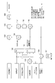
- FIG. 8 is a block diagram showing a configuration of CLCSO calculation logic in the combustion control device 140 according to some embodiments.
- the combustion load command value (CLCSO) is a parameter that makes the gas turbine inlet combustion gas temperature T1T dimensionless, and has a positive correlation with this gas turbine inlet combustion gas temperature T1T (proportional to the gas turbine inlet combustion gas temperature T1T). ) It is a parameter.
- This CLCSO is set to be 0% when the gas turbine inlet combustion gas temperature T1T is the lower limit value and 100% when the gas turbine inlet combustion gas temperature T1T is the upper limit value. For example, when the lower limit of the gas turbine inlet combustion gas temperature T1T is 700 ° C. and the upper limit of the gas turbine inlet combustion gas temperature T1T is 1500 ° C., CLCSO is expressed by the following equation (1).
- CLCSO (%) ⁇ (actual output-700 ° C MW) / (1500 ° C MW) -700 ° C MW) ⁇ x 100 ...
- the actual output is the measured gas turbine output (generator output).
- 700 ° C. MW is the output (generator output) of the gas turbine 1 when the gas turbine inlet combustion gas temperature T1T is 700 ° C., which is the lower limit value, in the environment where the gas turbine 1 is currently placed.
- 1500 ° C. MW is the output (generator output) of the gas turbine 1 when the gas turbine inlet combustion gas temperature T1T is 1500 ° C., which is the upper limit value, under the current environment of the gas turbine 1.
- the intake air temperature of the measured value, the IGV opening command value, and the intake flow rate of the measured value in the divider 153 (total compressed air).
- the value of 1500 ° C. MW (temperature control MW) is calculated based on the turbine bypass ratio (turbine bypass flow rate / intake flow rate) obtained by dividing the measured value of the turbine bypass flow rate (corresponding to the amount). That is, the value of 1500 ° C. MW in consideration of the IGV opening degree, the intake air temperature and the turbine bypass ratio is obtained.
- the function generator 152 calculates the value of 700 ° C. MW based on the intake air temperature, the IGV opening command value, and the turbine bypass ratio. That is, the value of 700 ° C. MW in consideration of the IGV opening degree, the intake air temperature and the turbine bypass ratio is obtained.
- the divider 154 divides the measured intake pressure (atmospheric pressure) and the standard atmospheric pressure set by the signal generator 161 to obtain the atmospheric pressure ratio (intake pressure / standard atmospheric pressure).
- the value of 1500 ° C. MW obtained by the function generator 151 is multiplied by the atmospheric pressure ratio obtained by the divider 154 to obtain the value of 1500 ° C. MW in consideration of the atmospheric pressure ratio.
- the value of 1500 ° C. MW obtained by the multiplier 155 may be output to the subtractor 157 via the learning circuit 162, or may be directly output to the subtractor 157.
- the learning circuit 162 is for correcting the deviation of the value of 1500 ° C. MW due to the deterioration of the characteristics of the gas turbine 1.
- the value of 700 ° C. MW obtained by the function generator 152 is multiplied by the atmospheric pressure ratio obtained by the divider 154 to obtain the value of 700 ° C. MW in consideration of the atmospheric pressure ratio.
- the value of 700 ° C. MW obtained by the multiplier 156 is subtracted from the value of 1500 ° C. MW obtained by the multiplier 155 (or corrected by the learning circuit 162) (1500 ° C. MW-700 ° C. MW: See equation (1) above).
- the value of 700 ° C. MW obtained by the multiplier 156 is subtracted from the actual output, that is, the generator output (gas turbine output) of the actually measured value (actual output-700 ° C. MW: see the above equation (1)). ..
- the CLCSO can be calculated.
- the output value of the divider 159 may be multiplied by 100.
- the CLC SO does not frequently repeat the opening / closing operation due to the minute fluctuation of the CLC SO due to the minute fluctuation of the gas turbine output (generator output). Therefore, the input value from the divider 159 is not immediately output as CLCSO, but is limited to a predetermined increase / decrease rate and output.
- the present disclosure is not limited to the above-mentioned embodiment, and includes a form in which the above-mentioned embodiment is modified and a form in which these forms are appropriately combined.
- the contents described in each of the above embodiments are grasped as follows, for example.
- the gas turbine combustor 4 according to at least one embodiment of the present disclosure is injected from a first fuel injector 41, a second fuel injector 42, a first fuel injector 41, and a second fuel injector 42.
- Low combustion for independently adjusting the supply amount of the low combustible fuel FL to the combustor liner 46 as a combustion part where the fuel F is burned and the first fuel injector 41 and the second fuel injector 42.
- the highly combustible fuel flow rate adjusting unit 240H and the combustion control device 140 as a controller are provided.
- the controller has a first ratio R1 of the highly combustible fuel FH to the entire first fuel F1 injected by the first fuel injector 41 and a second, depending on the operating state of the gas turbine 1.
- the first fuel injector 41 and the second fuel injector 42 have the first value a1 when the index indicating the operating state is the first value a1.
- the relative ratio R is set as described above, if the first fuel injector 41 is a combustor having a higher risk of flashback than the second fuel injector 42, the lower limit of output in the turndown operation should be reduced.
- the relative ratio R is desirable in order to achieve both the above and the reduction of the risk of flashback.
- the controller (combustion control device 140) has a first value depending on whether the index has the first value a1 or the second value a2.
- the low combustible fuel flow rate adjusting unit 240L and the high combustible fuel flow rate adjusting unit 240H may be controlled so that at least one of the ratio R1 and the second ratio R2 is different.
- the relative ratio R can be different depending on whether the index has the first value a1 or the second value a2.
- the controller (combustion control device 140) has a second value a2 rather than a first value a1. May be configured to control the low combustible fuel flow rate adjusting unit 240L and the high combustible fuel flow rate adjusting unit 240H so that the first ratio R1 becomes smaller.
- the risk of flashback in the first fuel injector 41 can be suppressed even if the load of the gas turbine 1 becomes relatively large.
- the controller (combustion control device 140) has a second ratio R2 when the index is the second value a2. It may be configured to control the low combustible fuel flow rate adjusting unit 240L and the high combustible fuel flow rate adjusting unit 240H so as to have the first ratio R1 or more.
- the load of the gas turbine 1 becomes relatively large.
- the second ratio R2 in the second fuel injector 42 can be made relatively large while suppressing the risk of flashback in the first fuel injector 41.
- the highly combustible fuel FH is a fuel having a relatively small environmental load such as hydrogen, the environmental load can be suppressed by relatively increasing the second ratio R2.
- the controller (combustion control device 140) has a second ratio R2 when the index is the second value a2. It may be configured to control the low combustible fuel flow rate adjusting unit 240L and the high combustible fuel flow rate adjusting unit 240H so as to be 0.5 or more.
- the second ratio R2 in the second fuel injector 42 can be made relatively large.
- the highly combustible fuel FH is a fuel having a relatively small environmental load such as hydrogen
- the environmental load can be suppressed by relatively increasing the second ratio R2.
- the first fuel injector 41 may be a premixed combustion type fuel injector, and the second fuel.
- the injector 42 may be a diffusion combustion type fuel injector.
- a diffusion combustion type fuel injector is a combustor having a lower risk of flashback than a premixed combustion type fuel injector.
- the second fuel injector 42 is a combustor having a smaller risk of flashback than the first fuel injector 41.
- a plurality of first fuel injectors 41 may be arranged around the second fuel injector 42.
- the enclosed fuel injector is at greater risk of flashback than the surrounding fuel injector. It gets smaller.
- the second fuel injector 42 is a combustor having a smaller risk of flashback than the first fuel injector 41.
- the first fuel injector 41 is arranged coaxially with the second fuel injector 42 and is a second fuel injector. It may be configured to inject the first fuel F1 from around 42.
- one fuel injector is placed coaxially with the other fuel injector, and each fuel injector is configured such that one fuel injector injects fuel from around the other fuel injector. If so, the other fuel injector has a lower risk of flashback than the one fuel injector.
- the second fuel injector 42 is a combustor having a smaller risk of flashback than the first fuel injector 41.
- the index representing the operating state may be the gas turbine inlet combustion gas temperature T1T.
- the gas turbine inlet combustion gas temperature T1T is an index that more accurately indicates the operating state of the gas turbine 1 as compared with, for example, the load (gas turbine output) of the gas turbine 1. According to the configuration of the above (10), since the relative ratio R can more accurately reflect the operating state of the gas turbine 1, the control accuracy of the relative ratio R can be improved.
- the index representing the operating state is a dimensionless value (CLCSO) of the gas turbine inlet combustion gas temperature T1T. It is good.
- the gas turbine inlet combustion gas temperature T1T is an index that more accurately indicates the operating state of the gas turbine 1 as compared with, for example, the load (gas turbine output) of the gas turbine 1.
- the gas turbine inlet combustion gas temperature T1T has become high, and it is difficult to measure the gas turbine inlet combustion gas temperature T1T for a long time.
- the configuration of (11) above by using the nondimensionalized value (CLCSO) of the gas turbine inlet combustion gas temperature T1T as the above index, it is not necessary to measure the gas turbine inlet combustion gas temperature T1T for a long time.
- the control accuracy of the relative ratio R can be easily improved.
- the index representing the operating state may be the load of the gas turbine 1.
- the load of the gas turbine 1 is inferior in accuracy as an index indicating the operating state of the gas turbine 1 as compared with, for example, the gas turbine inlet combustion gas temperature T1T, it is easy to obtain a value.
- the configuration for controlling the relative ratio R can be simplified.
- the low combustible fuel FL may be natural gas
- the high combustible fuel FH may be hydrogen or propane. , Or a mixture of hydrogen and propane.
- the low combustible fuel FL may be natural gas, which is a general fuel for the gas turbine 1.
- the highly combustible fuel FH may be any of hydrogen, propane, or a mixture of hydrogen and propane, which is a fuel having a higher combustion rate than natural gas. Thereby, the increase in the cost of the fuel F can be suppressed.
- the gas turbine 1 according to at least one embodiment of the present disclosure includes a gas turbine combustor 4 having any of the above configurations (1) to (13).
Landscapes
- Engineering & Computer Science (AREA)
- Chemical & Material Sciences (AREA)
- Combustion & Propulsion (AREA)
- Mechanical Engineering (AREA)
- General Engineering & Computer Science (AREA)
Abstract
Description
ターンダウン運転における出力下限値を小さくするためには、水素等のような燃焼速度が比較的大きい高燃焼性燃料を混焼させることが望ましい。
しかし、高燃焼性燃料の混焼率を大きくすると、逆火のリスクが高まる。すなわち、ターンダウン運転における出力下限値を小さくすることと逆火のリスクを下げることとはトレードオフの関係にある。
第1燃料噴射器と、
第2燃料噴射器と、
前記第1燃料噴射器及び前記第2燃料噴射器から噴射された燃料が燃焼する燃焼部と、
前記第1燃料噴射器及び前記第2燃料噴射器に対する低燃焼性燃料の供給量を互いに独立して調節するための低燃焼性燃料流量調節部と、
前記第1燃料噴射器及び前記第2燃料噴射器に対する、前記低燃焼性燃料よりも燃焼速度が高い高燃焼性燃料の供給量を互いに独立して調節するための高燃焼性燃料流量調節部と、
ガスタービンの運転状態に応じて、前記第1燃料噴射器によって噴射される第1燃料全体に対する前記高燃焼性燃料の第1比率、及び、前記第2燃料噴射器によって噴射される第2燃料全体に対する前記高燃焼性燃料の第2比率の相対比が変化するように前記低燃焼性燃料流量調節部及び前記高燃焼性燃料流量調節部を制御するように構成されたコントローラと、
を備える。
例えば、「ある方向に」、「ある方向に沿って」、「平行」、「直交」、「中心」、「同心」或いは「同軸」等の相対的或いは絶対的な配置を表す表現は、厳密にそのような配置を表すのみならず、公差、若しくは、同じ機能が得られる程度の角度や距離をもって相対的に変位している状態も表すものとする。
例えば、「同一」、「等しい」及び「均質」等の物事が等しい状態であることを表す表現は、厳密に等しい状態を表すのみならず、公差、若しくは、同じ機能が得られる程度の差が存在している状態も表すものとする。
例えば、四角形状や円筒形状等の形状を表す表現は、幾何学的に厳密な意味での四角形状や円筒形状等の形状を表すのみならず、同じ効果が得られる範囲で、凹凸部や面取り部等を含む形状も表すものとする。
一方、一の構成要素を「備える」、「具える」、「具備する」、「含む」、又は、「有する」という表現は、他の構成要素の存在を除外する排他的な表現ではない。
図1は、幾つかの実施形態に係るガスタービン1を示す概略構成図である。
幾つかの実施形態に係るガスタービン燃焼器の適用先の一例であるガスタービンについて、図1を参照して説明する。
幾つかの実施形態に係る圧縮機2は、圧縮機車室10と、圧縮機車室10の入口側に設けられ、空気を取り込むための空気取入口12と、圧縮機車室10及び後述するタービン車室22を共に貫通するように設けられたロータ8と、圧縮機車室10内に配置された各種の翼と、を備える。各種の翼は、空気取入口12側に設けられた入口案内翼14と、圧縮機車室10側に固定された複数の静翼16と、静翼16に対して交互に配列されるようにロータ8に植設された複数の動翼18と、を含む。なお、圧縮機2は、不図示の抽気室等の他の構成要素を備えていてもよい。このような圧縮機2において、空気取入口12から取り込まれた空気は、複数の静翼16及び複数の動翼18を通過して圧縮されることで高温高圧の圧縮空気となる。そして、高温高圧の圧縮空気は圧縮機2から後段の燃焼器4に送られる。
タービン車室22の下流側には、排気車室28を介して排気室30が連結されている。タービン6を駆動した後の燃焼ガスは、排気車室28及び排気室30を介して外部へ排出される。
図2は、幾つかの実施形態に係る燃焼器4を示す断面図である。図3は、幾つかの実施形態に係る燃焼器4の要部を示す断面図である。図4Aは、幾つかの実施形態に係る燃焼器4を燃焼器4の軸線方向に沿って下流側から上流側を見たときの各燃料噴射器の配置を模式的に示した図である。
図2、図3及び図4Aを参照して、幾つかの実施形態に係る燃焼器4の構成について説明する。
以下の説明では、第1燃料噴射器41から噴射される燃料Fを第1燃料F1とも称し、第2燃料噴射器42から噴射される燃料Fを第2燃料F2とも称する。
なお、燃焼器4は、燃焼ガスをバイパスさせるためのバイパス管(不図示)等の他の構成要素を備えていてもよい。
図3及び図4Aに示すように、パイロット燃焼バーナ50は、燃焼器ライナ46の中心軸に沿って配置されている。そして、パイロット燃焼バーナ50の外周側を囲むように、複数のメイン燃焼バーナ60が互いに離間して周方向に並んで配置されている。
パイロットノズル54は、燃焼器軸線Acを中心として軸線方向Daに延在している。
ここで、燃焼器軸線Acの延在方向である軸線方向Daの一方側であって燃焼ガスの流れに沿った上流側を上流側とし、他方側であって燃焼ガスの流れに沿った下流側を下流側とする。また、燃焼器軸線Acは、このパイロット燃焼バーナ50のバーナ軸線でもある。
すなわち、図2、図3及び図4Aに示したパイロット燃焼バーナ50(第2燃料噴射器42)は、拡散燃焼式の燃料噴射器である。
すなわち、図2、図3及び図4Aに示したメイン燃焼バーナ60(第1燃料噴射器41)は、予混合燃焼式の燃料噴射器である。
図4Bに示した燃焼器4では、第1燃料噴射器41及び第2燃料噴射器42は、内筒47内で周方向に並んで配置されている。図4Bに示した燃焼器4では、第1燃料噴射器41及び第2燃料噴射器42は、何れも予混合燃焼式の燃料噴射器であってもよい。
例えば発電用途のガスタービンでは、日中や夜間の電力需要の変動に対応するために、運転状態をターンダウン運転に切り替える場合がある。ターンダウン運転では、タービンを通過する燃焼ガスの流量を減少させて定格運転時に比べて低い出力でガスタービンが運転される。
ガスタービンをターンダウン運転することで出力を低下させると、燃焼器における燃焼温度が低下し、その結果未燃分である一酸化炭素や炭化水素等の物質の発生量の増加や、燃焼振動の発生を招いてしまう。しかし、上述した電力需要の変動に柔軟に対応するために、ターンダウン運転における出力下限値を小さくしてガスタービンの運用帯を広げることが求められている。
ターンダウン運転における出力下限値を小さくするためには、水素等のような燃焼速度が比較的大きい高燃焼性燃料を混焼させることが望ましい。
低燃焼性燃料FLとして例えば天然ガスを用いるとともに、高燃焼性燃料FHとして例えば水素、プロパン、又は水素とプロパンの混合物の何れかを用いることで、燃料Fのコストの増加を抑制できる。
図5は、幾つかの実施形態に係る燃焼器4に対する燃料Fの供給系統200の概略を示した図である。幾つかの実施形態に係るガスタービン1は、図5に示す燃料Fの供給系統200を含む。図5に示す燃料Fの供給系統200は、低燃焼性燃料FLを第1燃料噴射器41に供給するためのL1供給ライン211と、低燃焼性燃料FLを第2燃料噴射器42に供給するためのL2供給ライン212と、高燃焼性燃料FHを第1燃料噴射器41に供給するためのH1供給ライン221と、高燃焼性燃料FHを第2燃料噴射器42に供給するためのH2供給ライン222とを含む。
図5に示す燃料Fの供給系統200では、第1燃料噴射器41及び第2燃料噴射器42に対する低燃焼性燃料FLの供給量を互いに独立して調節するための低燃焼性燃料流量調節部240Lは、L1流量調節部241とL2流量調節部242とを含む。図5に示す燃料Fの供給系統200では、第1燃料噴射器41及び第2燃料噴射器42に対する高燃焼性燃料FHの供給量を互いに独立して調節するための高燃焼性燃料流量調節部240Hは、H1流量調節部243とH2流量調節部244とを含む。
すなわち、幾つかの実施形態では、第1燃料噴射器41によって噴射される第1燃料F1全体に対する高燃焼性燃料FHの第1比率R1、及び、第2燃料噴射器42によって噴射される第2燃料F2全体に対する高燃焼性燃料FHの第2比率R2は、燃焼制御装置140によって制御される。燃焼制御装置140の詳細については、後で説明する。
一方で、逆火のリスクは、燃料噴射器の構造や燃料噴射器の配置位置等によって異なるため、複数の燃料噴射器においてどの燃料噴射器も逆火のリスクが同じであるとは限らない。具体的には、例えば以下のとおりである。
一般的に、拡散燃焼式の燃料噴射器は予混合燃焼式の燃料噴射器よりも逆火のリスクが小さい燃焼器である。したがって、図2、図3及び図4Aに示す実施形態では、第2燃料噴射器42は、第1燃料噴射器41よりも逆火のリスクが小さい燃焼器となる。
ここで、図2、図3及び図4Aに示す実施形態では、第1燃料噴射器41は、第2燃料噴射器42の周囲に複数配置されている。したがって、仮に図2、図3及び図4Aに示す実施形態において第1燃料噴射器41と第2燃料噴射器42とが共に拡散燃焼式又は予混合燃焼式の燃料噴射器である場合のように、第1燃料噴射器41と第2燃料噴射器42とで燃料噴射器の構造が同様であれば、第2燃料噴射器は、第1燃料噴射器よりも逆火のリスクが小さい燃焼器となる。
一般的に、一方の燃料噴射器が他方の燃料噴射器と同軸に配置され、他方の燃料噴射器の周囲から一方の燃料噴射器が燃料を噴射するようにそれぞれの燃料噴射器が構成されている場合、他方の燃料噴射器は、一方の燃料噴射器よりも逆火のリスクが小さくなる。
したがって、仮に図4Bに示す実施形態において第1燃料噴射器41と第2燃料噴射器42とが共に拡散燃焼式又は予混合燃焼式の燃料噴射器である場合のように、第1燃料噴射器41と第2燃料噴射器42とで燃料噴射器の構造が同様であれば、第2燃料噴射器42は、第1燃料噴射器41よりも逆火のリスクが小さい燃焼器となる。
すなわち、幾つかの実施形態に係る燃焼器4では、燃焼制御装置140は、ガスタービン1の運転状態に応じて、第1比率R1及び第2比率R2の相対比Rが変化するように低燃焼性燃料流量調節部240L及び高燃焼性燃料流量調節部240Hを制御するように構成されている。
幾つかの実施形態に係る燃焼器4を備えるガスタービン1では、ターンダウン運転における出力下限値を小さくすることと逆火のリスクを下げることとの両立を図ることができ、ガスタービン1の運用帯を広げることができる。
以下、ガスタービン1の運転状態に応じた相対比Rの変更について詳細に説明する。
以下の説明では、相対比Rが第1比率R1を第2比率R2で除した値(R=R1/R2)であるものとして説明する。
図6Bは、第1比率R1及び第2比率R2と、ガスタービン1の運転状態を表す指標との関係の他の一例を示したグラフである。
図6C及び図6Dは、第1比率R1と、ガスタービン1の運転状態を表す指標との関係の他の例を示したグラフである。
図6Eは、第2比率R2と、ガスタービン1の運転状態を表す指標との関係の他の一例を示したグラフである。
一般的に、ガスタービン入口燃焼ガス温度T1Tは、例えばガスタービン1の負荷と比べて、ガスタービン1の運転状態をより正確に示す指標である。上記指標がガスタービン入口燃焼ガス温度T1Tであれば、上記相対比Rをガスタービン1の運転状態をより正確に反映されたものとすることができるので、上記相対比Rの制御精度を向上できる。
上述したように、ガスタービン入口燃焼ガス温度T1Tは、例えばガスタービン1の負荷と比べて、ガスタービン1の運転状態をより正確に示す指標である。しかし、近年のガスタービン1では、ガスタービン入口燃焼ガス温度T1Tが高温化しており、ガスタービン入口燃焼ガス温度T1Tを長時間計測することが困難となっている。
上記指標がCLCSOであれば、ガスタービン入口燃焼ガス温度T1Tを長時間計測する必要がなくなり、上記相対比Rの制御精度を容易に向上できる。
ガスタービン1の負荷は、例えばガスタービン入口燃焼ガス温度T1Tと比べるとガスタービン1の運転状態を表す指標としては精度が劣るものの、値の取得は容易である。
上記指標がガスタービン1の負荷であれば、上記相対比Rを制御するための構成を簡素化できる。
なお、第1比率R1の下限値は、0であってもよい。
なお、図6Cにおいて、b1<b2であり、図6Dにおいて、b3<b4である。
また、図示はしていないが、図6A又は図6Bにおいて、グラフ線の一部に、CLCSOの大きさに関わらず第1比率R1が一定の値となる部分があってもよい。
幾つかの実施形態に係る燃焼器4では、第1燃料噴射器41及び第2燃料噴射器42は、運転状態を表す指標(例えばCLCSO)が第1値a1(図6A及び図6B参照)となる場合には、第1値a1となる場合よりもガスタービン1の負荷が高負荷となる第2値a2(図6A及び図6B参照)となる場合よりも第1比率R1を第2比率R2で除した値(すなわち相対比R=R1/R2)が大きくなるように相対比Rが設定されるとよい。
例えば、図6A乃至図6Dに示すように、CLCSOが大きくなるにつれて、第1比率R1は、減少する傾向にあり、図6A及び図6Bに示すように、CLCSOの大小に関わらず、第2比率R2は、一定の値であれば、CLCSOが第1値a1となる場合には、CLCSOが第2値a2となる場合よりも第1比率R1を第2比率R2で除した値が大きくなる。なお、例えば図6Eに示すように、CLCSOが大きくなるにつれて、第2比率R2は、減少する傾向にある場合であっても、CLCSOが第1値a1となる場合には、CLCSOが第2値a2となる場合よりも第1比率R1を第2比率R2で除した値が大きくなるとよい。
すなわち、上記指標(例えばCLCSO)が第1値a1となる場合と第2値a2となる場合とで、第1比率R1又は第2比率R2の少なくとも何れか一方を異ならせることで上記指標が第1値a1となる場合と第2値a2となる場合とで上記相対比Rを異ならせることができる。
これにより、ガスタービン1の負荷が比較的大きくなっても、第2燃料噴射器42よりも逆火のリスクが高い第1燃料噴射器41における逆火のリスクを抑制できる。
したがって、第1燃料噴射器41が第2燃料噴射器42よりも逆火のリスクが高い燃焼器であるので、ガスタービン1の負荷が比較的大きくなった場合に第1燃料噴射器41における逆火のリスクを抑制しつつ、第2燃料噴射器42における第2比率R2を比較的大きくすることができる。例えば高燃焼性燃料FHが水素等の環境負荷が比較的小さい燃料であれば、第2比率R2を比較的大きくすることで環境負荷を抑制できる。
これにより、ガスタービン1の負荷が比較的大きくなった場合に第2燃料噴射器42における第2比率R2を比較的大きくすることができる。例えば高燃焼性燃料FHが水素等の環境負荷が比較的小さい燃料であれば、第2比率R2を比較的大きくすることで環境負荷を抑制できる。
図7は、幾つかの実施形態に係る燃焼制御装置140の全体概要図である。
図7に基づき、幾つかの実施形態に係る燃焼制御装置140について説明する。なお、燃焼制御装置140の各処理機能はソフトウェア(コンピュータプログラム)で構成され、コンピュータで実行されるが、これに限定するものではなく、ハードウェアで構成してもよい。
なお、タービンバイパス流量は、燃焼器4及びタービン6を通過せずに不図示のタービンバイパスラインを流れる圧縮空気の流量である。
不図示のタービンバイパスラインには圧縮空気のタービンバイパス流量を調整するための不図示のタービンバイパス弁が設けられている。これは圧縮機2の出口圧力(車室圧力)の調整などのために設けられている。
L1弁開度指令値は、L1流量調節部241における弁開度の指令値であり、L2弁開度指令値は、L2流量調節部242における弁開度の指令値である。H1弁開度指令値は、H1流量調節部243における弁開度の指令値であり、H2弁開度指令値は、H2流量調節部244における弁開度の指令値である。
これにより、燃焼制御装置140で演算されて設定された第1比率R1で、低燃焼性燃料FL及び高燃焼性燃料FHが第1燃料噴射器41に供給される。
これにより、燃焼制御装置140で演算されて設定された第2比率R2で、低燃焼性燃料FL及び高燃焼性燃料FHが第2燃料噴射器42に供給される。
図8は、幾つかの実施形態に係る燃焼制御装置140におけるCLCSOの算出ロジックの構成を示すブロック図である。
燃焼負荷指令値(CLCSO)は、ガスタービン入口燃焼ガス温度T1Tを無次元化したパラメータで、このガスタービン入口燃焼ガス温度T1Tと正の相関関係を持つ(ガスタービン入口燃焼ガス温度T1Tに比例する)パラメータである。このCLCSOは、ガスタービン入口燃焼ガス温度T1Tが下限値のときに0%、ガスタービン入口燃焼ガス温度T1Tが上限値のときに100%となるように設定される。例えば、ガスタービン入口燃焼ガス温度T1Tの下限値を700℃、ガスタービン入口燃焼ガス温度T1Tの上限値を1500℃としたとき、CLCSOは以下の(1)式で表される。
-700℃MW)}×100 ・・・・・(1)
なお、実出力は、実測値のガスタービン出力(発電機出力)である。700℃MWは、現時点でのガスタービン1がおかれている環境で、ガスタービン入口燃焼ガス温度T1Tが下限値である700℃のときのガスタービン1の出力(発電機出力)である。また、1500℃MWは、現時点でのガスタービン1の環境下で、ガスタービン入口燃焼ガス温度T1Tが上限値である1500℃のときのガスタービン1の出力(発電機出力)である。
乗算器155では、関数発生器151で求めた1500℃MWの値と、除算器154で求めた大気圧比とを乗算することにより、大気圧比をも考慮した1500℃MWの値を求める。
乗算器155で求めた1500℃MWの値は学習回路162を介して減算器157へ出力されてもよく、直接減算器157へ出力されてもよい。なお、学習回路162は、ガスタービン1の特性劣化等に起因する1500℃MWの値のずれを補正するためのものである。
乗算器156では、関数発生器152で求めた700℃MWの値と、除算器154で求めた大気圧比とを乗算することにより、大気圧比をも考慮した700℃MWの値を求める。
減算器158では、実出力、すなわち実測値の発電機出力(ガスタービン出力)から乗算器156で求めた700℃MWの値を減算する(実出力-700℃MW:上記(1)式参照)。
レート設定器160では、ガスタービン出力(発電機出力)の微小変動などによってCLCSOが微小変動することにより、燃料流量を調節するための各弁等が頻繁に開閉動作を繰り返すことがないようにするため、除算器159からの入力値を直ぐにCLCSOとして出力するのではなく、所定の増減レートに制限して出力する。
(1)本開示の少なくとも一実施形態に係るガスタービン燃焼器4は、第1燃料噴射器41と、第2燃料噴射器42と、第1燃料噴射器41及び第2燃料噴射器42から噴射された燃料Fが燃焼する燃焼部としての燃焼器ライナ46と、第1燃料噴射器41及び第2燃料噴射器42に対する低燃焼性燃料FLの供給量を互いに独立して調節するための低燃焼性燃料流量調節部240Lと、第1燃料噴射器41及び第2燃料噴射器42に対する、低燃焼性燃料FLよりも燃焼速度が高い高燃焼性燃料FHの供給量を互いに独立して調節するための高燃焼性燃料流量調節部240Hと、コントローラとしての燃焼制御装置140と、を備える。コントローラ(燃焼制御装置140)は、ガスタービン1の運転状態に応じて、第1燃料噴射器41によって噴射される第1燃料F1全体に対する高燃焼性燃料FHの第1比率R1、及び、第2燃料噴射器42によって噴射される第2燃料F2全体に対する高燃焼性燃料FHの第2比率R2の相対比Rが変化するように低燃焼性燃料流量調節部240L及び高燃焼性燃料流量調節部240Hを制御するように構成されている。
上記(7)の構成によれば、第2燃料噴射器42は、第1燃料噴射器41よりも逆火のリスクが小さい燃焼器となる。
上記(8)の構成によれば、第2燃料噴射器42は、第1燃料噴射器41よりも逆火のリスクが小さい燃焼器となる。
上記(9)の構成によれば、第2燃料噴射器42は、第1燃料噴射器41よりも逆火のリスクが小さい燃焼器となる。
上記(10)の構成によれば、上記相対比Rをガスタービン1の運転状態をより正確に反映されたものとすることができるので、上記相対比Rの制御精度を向上できる。
上記(11)の構成によれば、ガスタービン入口燃焼ガス温度T1Tを無次元化した値(CLCSO)を上記指標とすることで、ガスタービン入口燃焼ガス温度T1Tを長時間計測する必要がなくなり、上記相対比Rの制御精度を容易に向上できる。
上記(12)の構成によれば、ガスタービン1の負荷を上記指標とすることで、上記相対比Rを制御するための構成を簡素化できる。
2 圧縮機
4 ガスタービン燃焼器(燃焼器)
6 タービン
41 第1燃料噴射器
42 第2燃料噴射器
46 燃焼器ライナ
50 パイロット燃焼バーナ
60 メイン燃焼バーナ
140 燃焼制御装置
200 供給系統
240L 低燃焼性燃料流量調節部
240H 高燃焼性燃料流量調節部
Claims (14)
- 第1燃料噴射器と、
第2燃料噴射器と、
前記第1燃料噴射器及び前記第2燃料噴射器から噴射された燃料が燃焼する燃焼部と、
前記第1燃料噴射器及び前記第2燃料噴射器に対する低燃焼性燃料の供給量を互いに独立して調節するための低燃焼性燃料流量調節部と、
前記第1燃料噴射器及び前記第2燃料噴射器に対する、前記低燃焼性燃料よりも燃焼速度が高い高燃焼性燃料の供給量を互いに独立して調節するための高燃焼性燃料流量調節部と、
ガスタービンの運転状態に応じて、前記第1燃料噴射器によって噴射される第1燃料全体に対する前記高燃焼性燃料の第1比率、及び、前記第2燃料噴射器によって噴射される第2燃料全体に対する前記高燃焼性燃料の第2比率の相対比が変化するように前記低燃焼性燃料流量調節部及び前記高燃焼性燃料流量調節部を制御するように構成されたコントローラと、
を備えるガスタービン燃焼器。 - 前記第1燃料噴射器及び前記第2燃料噴射器は、前記運転状態を表す指標が第1値となる場合には、前記第1値となる場合よりも前記ガスタービンの負荷が高負荷となる第2値となる場合よりも前記第1比率を前記第2比率で除した値が大きくなるように前記相対比が設定される
請求項1に記載のガスタービン燃焼器。 - 前記コントローラは、前記指標が前記第1値となる場合と前記第2値となる場合とで、前記第1比率又は前記第2比率の少なくとも何れか一方が異なるように前記低燃焼性燃料流量調節部及び前記高燃焼性燃料流量調節部を制御するように構成されている
請求項2に記載のガスタービン燃焼器。 - 前記コントローラは、前記指標が前記第1値となる場合よりも前記第2値となる場合の方が前記第1比率が小さくなるように前記低燃焼性燃料流量調節部及び前記高燃焼性燃料流量調節部を制御するように構成されている
請求項2又は3に記載のガスタービン燃焼器。 - 前記コントローラは、前記指標が前記第2値となる場合に前記第2比率が前記第1比率以上となるように前記低燃焼性燃料流量調節部及び前記高燃焼性燃料流量調節部を制御するように構成されている
請求項2乃至4の何れか一項に記載のガスタービン燃焼器。 - 前記コントローラは、前記指標が前記第2値となる場合に前記第2比率が0.5以上となるように前記低燃焼性燃料流量調節部及び前記高燃焼性燃料流量調節部を制御するように構成されている
請求項2乃至5の何れか一項に記載のガスタービン燃焼器。 - 前記第1燃料噴射器は、予混合燃焼式の燃料噴射器であり、
前記第2燃料噴射器は、拡散燃焼式の燃料噴射器である
請求項1乃至6の何れか一項に記載のガスタービン燃焼器。 - 前記第1燃料噴射器は、前記第2燃料噴射器の周囲に複数配置されている
請求項1乃至7の何れか一項に記載のガスタービン燃焼器。 - 前記第1燃料噴射器は、前記第2燃料噴射器と同軸に配置され、前記第2燃料噴射器の周囲から前記第1燃料を噴射するように構成されている
請求項1乃至7の何れか一項に記載のガスタービン燃焼器。 - 前記運転状態を表す指標は、ガスタービン入口燃焼ガス温度である
請求項1乃至9の何れか一項に記載のガスタービン燃焼器。 - 前記運転状態を表す指標は、ガスタービン入口燃焼ガス温度を無次元化した値である
請求項1乃至9の何れか一項に記載のガスタービン燃焼器。 - 前記運転状態を表す指標は、前記ガスタービンの負荷である
請求項1乃至9の何れか一項に記載のガスタービン燃焼器。 - 前記低燃焼性燃料は、天然ガスであり、
前記高燃焼性燃料は、水素、プロパン、又は水素とプロパンの混合物の何れかである
請求項1乃至12の何れか一項に記載のガスタービン燃焼器。 - 請求項1乃至13の何れか一項に記載のガスタービン燃焼器、
を備えるガスタービン。
Priority Applications (5)
| Application Number | Priority Date | Filing Date | Title |
|---|---|---|---|
| KR1020237021005A KR20230112676A (ko) | 2021-01-08 | 2021-12-28 | 가스 터빈 연소기 및 가스 터빈 |
| US18/269,115 US20240125476A1 (en) | 2021-01-08 | 2021-12-28 | Gas turbine combustor and gas turbine |
| DE112021005603.4T DE112021005603T5 (de) | 2021-01-08 | 2021-12-28 | Gasturbinenbrennkammer und gasturbine |
| CN202180089044.4A CN116710643A (zh) | 2021-01-08 | 2021-12-28 | 燃气轮机燃烧器及燃气轮机 |
| JP2022574034A JP7456012B2 (ja) | 2021-01-08 | 2021-12-28 | ガスタービン燃焼器及びガスタービン |
Applications Claiming Priority (2)
| Application Number | Priority Date | Filing Date | Title |
|---|---|---|---|
| JP2021-002117 | 2021-01-08 | ||
| JP2021002117 | 2021-01-08 |
Publications (1)
| Publication Number | Publication Date |
|---|---|
| WO2022149540A1 true WO2022149540A1 (ja) | 2022-07-14 |
Family
ID=82357752
Family Applications (1)
| Application Number | Title | Priority Date | Filing Date |
|---|---|---|---|
| PCT/JP2021/048742 WO2022149540A1 (ja) | 2021-01-08 | 2021-12-28 | ガスタービン燃焼器及びガスタービン |
Country Status (6)
| Country | Link |
|---|---|
| US (1) | US20240125476A1 (ja) |
| JP (1) | JP7456012B2 (ja) |
| KR (1) | KR20230112676A (ja) |
| CN (1) | CN116710643A (ja) |
| DE (1) | DE112021005603T5 (ja) |
| WO (1) | WO2022149540A1 (ja) |
Citations (3)
| Publication number | Priority date | Publication date | Assignee | Title |
|---|---|---|---|---|
| JP5873239B2 (ja) * | 2009-10-23 | 2016-03-01 | ゼネラル・エレクトリック・カンパニイ | 燃料フレキシブル燃焼器システム及び方法 |
| JP6431893B2 (ja) * | 2013-03-15 | 2018-11-28 | ゼネラル・エレクトリック・カンパニイ | ガスタービンの燃料混合および制御のためのシステムおよび方法 |
| WO2019048387A1 (en) * | 2017-09-05 | 2019-03-14 | Siemens Aktiengesellschaft | GAS TURBINE COMBUSTION CHAMBER ASSEMBLY WITH TRAPPED TOURBILLON ELEMENT |
Family Cites Families (2)
| Publication number | Priority date | Publication date | Assignee | Title |
|---|---|---|---|---|
| JP5566683B2 (ja) | 2009-12-25 | 2014-08-06 | 三菱重工業株式会社 | ガスタービン |
| JP7348591B2 (ja) | 2019-06-20 | 2023-09-21 | マツダ株式会社 | 見守り支援方法、見守り管理装置 |
-
2021
- 2021-12-28 DE DE112021005603.4T patent/DE112021005603T5/de active Pending
- 2021-12-28 KR KR1020237021005A patent/KR20230112676A/ko unknown
- 2021-12-28 JP JP2022574034A patent/JP7456012B2/ja active Active
- 2021-12-28 CN CN202180089044.4A patent/CN116710643A/zh active Pending
- 2021-12-28 WO PCT/JP2021/048742 patent/WO2022149540A1/ja active Application Filing
- 2021-12-28 US US18/269,115 patent/US20240125476A1/en active Pending
Patent Citations (3)
| Publication number | Priority date | Publication date | Assignee | Title |
|---|---|---|---|---|
| JP5873239B2 (ja) * | 2009-10-23 | 2016-03-01 | ゼネラル・エレクトリック・カンパニイ | 燃料フレキシブル燃焼器システム及び方法 |
| JP6431893B2 (ja) * | 2013-03-15 | 2018-11-28 | ゼネラル・エレクトリック・カンパニイ | ガスタービンの燃料混合および制御のためのシステムおよび方法 |
| WO2019048387A1 (en) * | 2017-09-05 | 2019-03-14 | Siemens Aktiengesellschaft | GAS TURBINE COMBUSTION CHAMBER ASSEMBLY WITH TRAPPED TOURBILLON ELEMENT |
Also Published As
| Publication number | Publication date |
|---|---|
| CN116710643A (zh) | 2023-09-05 |
| US20240125476A1 (en) | 2024-04-18 |
| KR20230112676A (ko) | 2023-07-27 |
| JP7456012B2 (ja) | 2024-03-26 |
| DE112021005603T5 (de) | 2023-08-03 |
| JPWO2022149540A1 (ja) | 2022-07-14 |
Similar Documents
| Publication | Publication Date | Title |
|---|---|---|
| US11067280B2 (en) | Centerbody injector mini mixer fuel nozzle assembly | |
| US10502425B2 (en) | Contoured shroud swirling pre-mix fuel injector assembly | |
| RU2621566C2 (ru) | Топливовоздушная форсунка (варианты ), камера сгорания для газотурбинного двигателя (варианты ) и способ работы топливовоздушной форсунки (варианты ) | |
| EP1087178B1 (en) | Pre-mixing chamber for gas turbines | |
| US10352569B2 (en) | Multi-point centerbody injector mini mixing fuel nozzle assembly | |
| US11408356B2 (en) | Method of operating a combustion system with main and pilot fuel circuits | |
| US10465909B2 (en) | Mini mixing fuel nozzle assembly with mixing sleeve | |
| JP6626743B2 (ja) | 燃焼装置及びガスタービン | |
| JP2015048759A (ja) | ガスタービン燃焼システム | |
| JP2015045331A (ja) | ガスタービンエンジンの燃焼室における燃料の分布を制御するためのシステムおよび方法 | |
| JP2013140003A5 (ja) | ||
| JP4409566B2 (ja) | 希薄予混合型燃焼装置とその制御方法 | |
| US10865989B2 (en) | Combustor arrangement having arranged in an upstream to downstream flow sequence a radial swirler, pre-chamber with a convergent portion and a combustion chamber | |
| CN109072782B (zh) | 燃烧器及燃气轮机 | |
| US9322336B2 (en) | Fuel nozzle for gas turbine | |
| RU2570480C2 (ru) | Способ смешивания разбавляющего воздуха в системе последовательного сгорания газовой турбины | |
| RU2657075C2 (ru) | Жидкостная пусковая трубка с кожухом | |
| JP2014102066A (ja) | ガスタービンの燃焼セクションに燃料を供給するための燃料供給システム | |
| US20140157788A1 (en) | Fuel nozzle for gas turbine | |
| WO2022149540A1 (ja) | ガスタービン燃焼器及びガスタービン | |
| JP6193131B2 (ja) | 燃焼器およびガスタービン | |
| JP4995657B2 (ja) | ガスタービンエンジン燃焼器のミキサ組立体への燃料流量を能動的に制御するための装置 | |
| WO2013151162A1 (ja) | ガスタービン燃焼器 | |
| WO2024116963A1 (ja) | ガスタービンの運転方法 | |
| US10955141B2 (en) | Dual-fuel fuel nozzle with gas and liquid fuel capability |
Legal Events
| Date | Code | Title | Description |
|---|---|---|---|
| 121 | Ep: the epo has been informed by wipo that ep was designated in this application |
Ref document number: 21917760 Country of ref document: EP Kind code of ref document: A1 |
|
| ENP | Entry into the national phase |
Ref document number: 2022574034 Country of ref document: JP Kind code of ref document: A |
|
| ENP | Entry into the national phase |
Ref document number: 20237021005 Country of ref document: KR Kind code of ref document: A |
|
| WWE | Wipo information: entry into national phase |
Ref document number: 18269115 Country of ref document: US |
|
| WWE | Wipo information: entry into national phase |
Ref document number: 202180089044.4 Country of ref document: CN |
|
| 122 | Ep: pct application non-entry in european phase |
Ref document number: 21917760 Country of ref document: EP Kind code of ref document: A1 |