WO2024116963A1 - ガスタービンの運転方法 - Google Patents
ガスタービンの運転方法 Download PDFInfo
- Publication number
- WO2024116963A1 WO2024116963A1 PCT/JP2023/041777 JP2023041777W WO2024116963A1 WO 2024116963 A1 WO2024116963 A1 WO 2024116963A1 JP 2023041777 W JP2023041777 W JP 2023041777W WO 2024116963 A1 WO2024116963 A1 WO 2024116963A1
- Authority
- WO
- WIPO (PCT)
- Prior art keywords
- hydrogen
- mixing ratio
- hydrogen mixing
- ratio
- fuel
- Prior art date
Links
- 238000000034 method Methods 0.000 title claims abstract description 66
- 229910052739 hydrogen Inorganic materials 0.000 claims abstract description 375
- 239000001257 hydrogen Substances 0.000 claims abstract description 375
- UFHFLCQGNIYNRP-UHFFFAOYSA-N Hydrogen Chemical compound [H][H] UFHFLCQGNIYNRP-UHFFFAOYSA-N 0.000 claims abstract description 374
- 238000002485 combustion reaction Methods 0.000 claims abstract description 272
- 239000000446 fuel Substances 0.000 claims abstract description 163
- 239000007789 gas Substances 0.000 claims abstract description 75
- XLYOFNOQVPJJNP-UHFFFAOYSA-N water Substances O XLYOFNOQVPJJNP-UHFFFAOYSA-N 0.000 claims description 16
- 238000009792 diffusion process Methods 0.000 claims description 10
- 238000011017 operating method Methods 0.000 claims description 7
- VNWKTOKETHGBQD-UHFFFAOYSA-N methane Chemical compound C VNWKTOKETHGBQD-UHFFFAOYSA-N 0.000 description 38
- 206010016754 Flashback Diseases 0.000 description 26
- 239000003345 natural gas Substances 0.000 description 19
- 238000010344 co-firing Methods 0.000 description 15
- CURLTUGMZLYLDI-UHFFFAOYSA-N Carbon dioxide Chemical compound O=C=O CURLTUGMZLYLDI-UHFFFAOYSA-N 0.000 description 12
- 239000000567 combustion gas Substances 0.000 description 9
- 238000011144 upstream manufacturing Methods 0.000 description 8
- 229910002092 carbon dioxide Inorganic materials 0.000 description 6
- 238000010586 diagram Methods 0.000 description 6
- 239000001569 carbon dioxide Substances 0.000 description 5
- 230000014509 gene expression Effects 0.000 description 5
- 238000002347 injection Methods 0.000 description 5
- 239000007924 injection Substances 0.000 description 5
- 239000002184 metal Substances 0.000 description 4
- 239000000498 cooling water Substances 0.000 description 3
- 238000009841 combustion method Methods 0.000 description 2
- 238000012986 modification Methods 0.000 description 2
- 230000004048 modification Effects 0.000 description 2
- 238000010248 power generation Methods 0.000 description 2
- 230000007704 transition Effects 0.000 description 2
- 238000010792 warming Methods 0.000 description 2
- 238000004590 computer program Methods 0.000 description 1
- 238000006073 displacement reaction Methods 0.000 description 1
- 230000000694 effects Effects 0.000 description 1
- 238000010304 firing Methods 0.000 description 1
- 239000012530 fluid Substances 0.000 description 1
- 239000002803 fossil fuel Substances 0.000 description 1
- 150000002431 hydrogen Chemical class 0.000 description 1
- 239000000463 material Substances 0.000 description 1
- 239000007800 oxidant agent Substances 0.000 description 1
- 230000001590 oxidative effect Effects 0.000 description 1
Images


Classifications
-
- F—MECHANICAL ENGINEERING; LIGHTING; HEATING; WEAPONS; BLASTING
- F02—COMBUSTION ENGINES; HOT-GAS OR COMBUSTION-PRODUCT ENGINE PLANTS
- F02C—GAS-TURBINE PLANTS; AIR INTAKES FOR JET-PROPULSION PLANTS; CONTROLLING FUEL SUPPLY IN AIR-BREATHING JET-PROPULSION PLANTS
- F02C7/00—Features, components parts, details or accessories, not provided for in, or of interest apart form groups F02C1/00 - F02C6/00; Air intakes for jet-propulsion plants
- F02C7/22—Fuel supply systems
-
- F—MECHANICAL ENGINEERING; LIGHTING; HEATING; WEAPONS; BLASTING
- F02—COMBUSTION ENGINES; HOT-GAS OR COMBUSTION-PRODUCT ENGINE PLANTS
- F02C—GAS-TURBINE PLANTS; AIR INTAKES FOR JET-PROPULSION PLANTS; CONTROLLING FUEL SUPPLY IN AIR-BREATHING JET-PROPULSION PLANTS
- F02C9/00—Controlling gas-turbine plants; Controlling fuel supply in air- breathing jet-propulsion plants
- F02C9/26—Control of fuel supply
- F02C9/40—Control of fuel supply specially adapted to the use of a special fuel or a plurality of fuels
Definitions
- the present disclosure relates to a method of operating a gas turbine.
- This application claims priority based on Japanese Patent Application No. 2022-192566, filed with the Japan Patent Office on December 1, 2022, the contents of which are incorporated herein by reference.
- At least one embodiment of the present disclosure aims to increase the hydrogen co-firing rate while suppressing flame backflow, etc., during gas turbine operation.
- a method of operating a gas turbine comprising: A method for operating a gas turbine having a combustor that has a main nozzle and a pilot nozzle and can use hydrogen and a fuel other than hydrogen as fuel, comprising the steps of: The ratio of the hydrogen mixing ratio of the fuel injected from the pilot nozzle to the hydrogen mixing ratio of the fuel injected from the main nozzle is a second ratio during high hydrogen mixing ratio operation in which the hydrogen mixing ratio is higher than that during low hydrogen mixing ratio operation, which is larger than a first ratio during low hydrogen mixing ratio operation.
- FIG. 1 is a schematic diagram illustrating a gas turbine according to some embodiments.
- 1 is a cross-sectional view of a combustor according to some embodiments.
- 1 is a cross-sectional view illustrating a main portion of a combustor according to some embodiments.
- 2 is a diagram illustrating an arrangement of fuel injectors in a combustor according to some embodiments, viewed from the downstream side to the upstream side along an axial direction of the combustor;
- FIG. FIG. 2 is a schematic diagram of a fuel supply system for a combustor according to some embodiments.
- 1 is a graph showing an example of the relationship between the hydrogen mixing ratio of each combustion burner and the hydrogen mixing ratio of the entire combustor during rated operation.
- FIG. 1 is a graph showing an example of the relationship between the hydrogen mixing ratio of each combustion burner and the hydrogen mixing ratio of the entire combustor during rated operation.
- FIG. 1 is a graph showing an example of the relationship between the
- FIG. 6B is a graph showing an example of the relationship between the ratio of the hydrogen mixing ratio in the pilot combustion burner to the hydrogen mixing ratio in the main combustion burner and the hydrogen mixing ratio in the entire combustor, when the hydrogen mixing ratios of each combustion burner and the hydrogen mixing ratio in the entire combustor have the relationship shown in FIG. 6A .
- 13 is a graph showing another example of the relationship between the hydrogen mixing ratio of each combustion burner and the hydrogen mixing ratio of the entire combustor during rated operation.
- FIG. 7B is a graph showing an example of the relationship between the ratio of the hydrogen mixing ratio in the pilot combustion burner to the hydrogen mixing ratio in the main combustion burner and the hydrogen mixing ratio in the entire combustor, when the hydrogen mixing ratios of each combustion burner and the hydrogen mixing ratio in the entire combustor have the relationship shown in FIG. 7A .
- 13 is a graph showing yet another example of the relationship between the hydrogen mixing ratio of each combustion burner and the hydrogen mixing ratio of the entire combustor during rated operation.
- FIG. 8B is a graph showing an example of the relationship between the ratio of the hydrogen mixing ratio in the pilot combustion burner to the hydrogen mixing ratio in the main combustion burner and the hydrogen mixing ratio in the entire combustor, when the hydrogen mixing ratios of each combustion burner and the hydrogen mixing ratio in the entire combustor have the relationship shown in FIG. 8A .
- 1 is a graph showing an example of the relationship between the hydrogen mixing ratio of each combustion burner and the hydrogen mixing ratio of the entire combustor during partial load operation.
- 9B is a graph showing an example of the relationship between the ratio of the hydrogen mixing ratio in the pilot combustion burner to the hydrogen mixing ratio in the main combustion burner and the hydrogen mixing ratio in the entire combustor, when the hydrogen mixing ratios of each combustion burner and the hydrogen mixing ratio in the entire combustor have the relationship shown in FIG. 9A .
- expressions indicating that things are in an equal state such as “identical,””equal,” and “homogeneous,” not only indicate a state of strict equality, but also indicate a state in which there is a tolerance or a difference to the extent that the same function is obtained.
- expressions describing shapes such as a rectangular shape or a cylindrical shape do not only refer to rectangular shapes, cylindrical shapes, etc. in the strict geometric sense, but also refer to shapes that include uneven portions, chamfered portions, etc., to the extent that the same effect is obtained.
- the expressions “comprise,””include,””have,””includes,” or “have” of one element are not exclusive expressions excluding the presence of other elements.
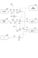
- FIG. 1 is a schematic configuration diagram showing a gas turbine 1 according to some embodiments.
- a gas turbine which is an example of an application of a gas turbine operation method according to some embodiments, will be described with reference to FIG.
- a gas turbine 1 operated by a gas turbine operating method includes a compressor 2 for generating compressed air as an oxidant, a gas turbine combustor 4 for generating combustion gas using the compressed air and fuel, and a turbine 6 configured to be rotationally driven by the combustion gas.
- a generator (not shown) is connected to the turbine 6, and power is generated by the rotational energy of the turbine 6.
- the gas turbine combustor 4 is also simply referred to as the combustor 4.
- a compressor 2 includes a compressor casing 10, an air intake 12 provided on the inlet side of the compressor casing 10 for taking in air, a rotor 8 provided to penetrate both the compressor casing 10 and a turbine casing 22 described later, and various blades arranged in the compressor casing 10.
- the various blades include an inlet guide vane 14 provided on the air intake 12 side, a plurality of stator vanes 16 fixed on the compressor casing 10 side, and a plurality of rotor blades 18 planted on the rotor 8 so as to be arranged alternately with respect to the stator vanes 16.
- the compressor 2 may include other components such as an unillustrated bleed chamber.
- air taken in from the air intake 12 is compressed by passing through the plurality of stator vanes 16 and the plurality of rotor blades 18 to become high-temperature, high-pressure compressed air.
- the high-temperature, high-pressure compressed air is then sent from the compressor 2 to a downstream combustor 4.
- the combustor 4 is disposed within the casing 20. As shown in FIG. 1, a plurality of combustors 4 may be disposed within the casing 20 in an annular shape centered around the rotor 8. The combustor 4 is supplied with fuel and compressed air generated by the compressor 2, and the fuel is combusted to generate combustion gas, which is the working fluid of the turbine 6. The combustion gas is then sent from the combustor 4 to the downstream turbine 6.
- An example configuration of the combustor 4 according to some embodiments will be described later.
- the turbine 6 includes a turbine casing 22 and various blades arranged in the turbine casing 22.
- the various blades include a plurality of stator vanes 24 fixed to the turbine casing 22 side and a plurality of moving blades 26 implanted in the rotor 8 so as to be arranged alternately with respect to the stator vanes 24.
- the turbine 6 may include other components such as outlet guide vanes.
- the rotor 8 is driven to rotate by the combustion gas passing through the plurality of stator vanes 24 and the plurality of moving blades 26. This drives a generator connected to the rotor 8.
- An exhaust chamber 30 is connected to the downstream side of the turbine casing 22 via an exhaust casing 28. The combustion gas after driving the turbine 6 is exhausted to the outside via the exhaust casing 28 and the exhaust chamber 30.
- FIG. 2 is a cross-sectional view showing the combustor 4 according to some embodiments.
- Fig. 3 is a cross-sectional view showing a main part of the combustor 4 according to some embodiments.
- Fig. 4 is a diagram showing a schematic arrangement of each fuel injector when the combustor 4 according to some embodiments is viewed from the downstream side to the upstream side along the axial direction of the combustor 4. 2, 3 and 4, configurations of the combustor 4 according to some embodiments will be described.
- each combustor 4 includes a combustor liner 46 provided in a combustor chamber 40 defined by a casing 20, and a main combustion burner 60 and a pilot combustion burner 50, which are fuel injectors respectively arranged within the combustor liner 46.
- the combustor 4 further includes an outer casing 45 provided on the outer circumferential side of an inner casing 47 of the combustor liner 46 inside the casing 20.
- An air passage 43 through which compressed air flows is formed on the outer circumferential side of the inner casing 47 and on the inner circumferential side of the outer casing 45.
- the combustor 4 may include other components such as a bypass pipe (not shown) for bypassing the combustion gas.
- the combustor liner 46 has an inner cylinder 47 disposed around the pilot combustion burner 50 and the multiple main combustion burners 60, and a transition piece 48 connected to the tip of the inner cylinder 47. That is, the combustor liner 46 corresponds to a combustion section in which the fuel F injected from the main combustion burner 60 and the pilot combustion burner 50 is combusted. 3 and 4, the pilot combustion burner 50 is disposed along the central axis of the combustor liner 46. A plurality of main combustion burners 60 are disposed spaced apart from each other and aligned in the circumferential direction so as to surround the outer periphery of the pilot combustion burner 50.
- the pilot combustion burner 50 has a pilot nozzle 54 connected to a fuel port 52, a pilot burner cylinder 56 arranged to surround the pilot nozzle 54, and a plurality of swirlers (swirl plates) 58 provided on the outer periphery of the pilot nozzle 54.
- the pilot nozzle 54 extends in an axial direction Da about the combustor axis Ac.
- the upstream side in the direction of the axial direction Da which is the direction in which the combustor axis Ac extends, is defined as the upstream side
- the downstream side in the direction of the combustion gas flow is defined as the downstream side.
- the combustor axis Ac is also the burner axis of the pilot combustion burner 50.
- the downstream end of the pilot nozzle 54 is formed with an injection hole (not shown) for injecting fuel F.
- a plurality of swivel plates 58 are provided upstream of the position where the injection hole is formed in the pilot nozzle 54. Each swivel plate 58 is for swirling the compressed air around the combustor axis Ac. Each swivel plate 58 extends in a direction including a radial component from the outer periphery of the pilot nozzle 54 and is close to the inner periphery of the pilot burner tube 56.
- the pilot burner tube 56 has a main body portion 56a located on the outer periphery of the pilot nozzle 54 and a cone portion 56b connected to the downstream side of the main body portion 56a and gradually expanding in diameter toward the downstream side.
- the plurality of swivel plates 58 are close to the inner periphery of the main body portion 56a in the pilot burner tube 56.
- the pilot nozzle 54 has a water flow path (not shown) for suppressing the flame temperature to suppress NOx and the metal temperature of the cone portion 56b, and is configured to be able to inject water.
- the main combustion burner 60 has a main nozzle 64 connected to a fuel port 62, a main burner tube 66 arranged to surround the main nozzle 64, an extension tube 65 connecting the main burner tube 66 to the combustor liner 46 (e.g., the inner tube 47), and a swirler (swirl plate) 70 provided on the outer periphery of the main nozzle 64.
- a swirler swirl plate
- the main nozzle 64 is a rod-shaped nozzle extending in the axial direction Da centered on the burner axis Ab, which is parallel to the combustor axis Ac. Since the burner axis Ab of the main combustion burner 60 is parallel to the combustor axis Ac, the axial direction Da relative to the combustor axis Ac and the axial direction Da relative to the burner axis Ab are in the same direction. Furthermore, the upstream side of the axial direction Da relative to the combustor axis Ac is the upstream side of the axial direction Da relative to the burner axis Ab, and the downstream side of the axial direction Da relative to the combustor axis Ac is the downstream side of the axial direction Da relative to the burner axis Ab.
- Injection holes for injecting fuel F are formed in the middle of the main nozzle 64 in the axial direction Da.
- a number of swivel plates 70 are provided near the positions where the injection holes are formed in the main nozzle 64.
- Each swivel plate 70 is for swirling the compressed air around the burner axis Ab.
- Each swivel plate 70 extends from the outer periphery of the main nozzle 64 in a direction that includes a radial component, and is close to the inner circumferential surface of the main burner cylinder 66.
- the main burner cylinder 66 is located on the outer periphery of the main nozzle 64.
- the compressed air generated by the compressor 2 is supplied from the casing inlet 40a into the combustor casing 40, and then flows from the combustor casing 40 through the air passage 43 into the pilot burner tube 56 and the multiple main burner tubes 66.
- pilot combustion burner 50 fuel F injected from a pilot nozzle 54 is ejected together with compressed air from the downstream end of a pilot burner tube 56. This fuel F undergoes diffusion combustion or premixed combustion in the combustor liner 46. That is, the pilot fired burner 50 shown in Figures 2, 3 and 4 is a diffusion or premixed firing type fuel injector.
- the main combustion burner 60 In the main combustion burner 60, compressed air and fuel F injected from the main nozzle 64 are mixed in a main burner cylinder 66 to form a premixed gas PM. In the main combustion burner 60, the premixed gas PM is injected from the downstream end of the extension tube 65. The fuel F in this premixed gas PM is premixed and combusted in the combustor liner 46. That is, the main combustion burner 60 shown in Figures 2, 3 and 4 is a premixed combustion type fuel injector.
- an injection hole for injecting fuel F may be formed in the swivel plate 70, and fuel F may be injected from here into the main burner tube 66.
- the part corresponding to the rod-shaped main nozzle 64 described above forms a hub rod, and the main nozzle is formed by having this hub rod and multiple swivel plates 70. Fuel F is supplied from the outside into the hub rod, and fuel F is supplied from this hub rod to the swivel plates 70.
- the combustor 4 is configured to be able to use, for example, natural gas as in a conventional combustor, and also to use hydrogen as the fuel F.
- natural gas as the fuel F will be referred to as natural gas fuel FN, or simply as natural gas.
- hydrogen as the fuel F will be referred to as hydrogen fuel FH, or simply as hydrogen.
- natural gas fuel FN, hydrogen fuel FH, and mixed fuel FM of natural gas fuel FN and hydrogen fuel FH will be referred to as fuel F when there is no need to particularly distinguish between them or when these fuels are referred to collectively.
- Fig. 5 is a diagram showing an outline of a supply system 200 of fuel F to the combustor 4 according to some embodiments.
- the gas turbine 1 includes the supply system 200 of fuel F shown in Fig. 5.
- the supply system 200 of fuel F shown in Fig. 5 includes a first supply line 211 for supplying natural gas fuel FN to the main combustion burner 60, a second supply line 212 for supplying natural gas fuel FN to the pilot combustion burner 50, a third supply line 221 for supplying hydrogen fuel FH to the main combustion burner 60 and the pilot combustion burner 50, and a fourth supply line 222 for supplying hydrogen fuel FH to the pilot combustion burner 50.
- the natural gas fuel FN is supplied from a supply source 201 of the natural gas fuel FN via a natural gas supply line 210.
- the first supply line 211 and the second supply line 212 branch off at a branch point 231.
- the first supply line 211 is provided with a first adjustment valve 241 for adjusting the amount of fuel F supplied to the main combustion burner 60.
- the downstream end of the first supply line 211 is connected to a fuel port 62 to which a main nozzle 64 of the main combustion burner 60 is connected.
- the second supply line 212 is provided with a second control valve 242 for adjusting the amount of fuel F supplied to the pilot combustion burner 50.
- the downstream end of the second supply line 212 is connected to a fuel port 52 to which a pilot nozzle 54 of the pilot combustion burner 50 is connected.
- the hydrogen fuel FH is supplied from a supply source 202 of the hydrogen fuel FH via a hydrogen supply line 220.
- the third supply line 221 and the fourth supply line 222 branch off at a branch point 232.
- the third supply line 221 is provided with a third adjustment valve 243 for adjusting the supply amount of hydrogen fuel FH to the main combustion burner 60 and the pilot combustion burner 50.
- the downstream end of the third supply line 221 is connected to the natural gas supply line 210 at a junction 233 upstream of a branching portion 231 in the natural gas supply line 210. That is, the third adjustment valve 243 is an adjustment valve for adjusting the amount of hydrogen fuel FH added to the natural gas fuel FN flowing through the natural gas supply line 210 .
- the fourth supply line 222 is provided with a fourth adjustment valve 244 for adjusting the amount of hydrogen fuel FH supplied to the pilot combustion burner 50.
- the downstream end of the fourth supply line 222 is connected to the second supply line 212 at a junction 234 downstream of the second adjustment valve 242 in the second supply line 212.
- the fourth control valve 244 is a control valve that can adjust the amount of hydrogen fuel FH added to the natural gas fuel FN or the mixed fuel FM of the natural gas fuel FN and the hydrogen fuel FH flowing through the second supply line 212.
- the second control valve 242 and opening the fourth control valve 244 only the hydrogen fuel FH can be supplied to the pilot combustion burner 50.
- the opening degrees of the first control valve 241, the second control valve 242, the third control valve 243, and the fourth control valve 244 can be adjusted to adjust the hydrogen mixing ratio (calorie ratio), which is the ratio of hydrogen fuel FH in the fuel F injected in the main combustion burner 60 and the pilot combustion burner 50.
- the hydrogen mixing ratio calorie ratio
- the first control valve 241, the second control valve 242, the third control valve 243, and the fourth control valve 244 are controlled by a controller configured to be able to control each of these control valves.
- the controller is realized by the combustion control device 140 of the gas turbine 1.
- Each processing function of the combustion control device 140 is configured as software (computer program) and executed by a computer, but is not limited to this and may be configured as hardware.
- the gas turbine 1 includes a water supply line 215 for supplying cooling water to the pilot combustion burner 50. Although detailed description will be omitted, supplying cooling water suppresses the flame temperature that increases when the hydrogen mixing ratio in the pilot combustion burner 50 is increased, thereby suppressing the generation of NOx and suppressing the metal temperature of the cone portion 56b of the pilot combustion burner 50. Cooling water may be supplied to the pilot-fired burner 50 from a water source 205 via a water supply line 215 .
- the water supply line 215 is provided with a water supply amount adjustment valve 251 for adjusting the amount of water supplied to the pilot combustion burner 50. Although a detailed description will be omitted, the water supply amount adjustment valve 251 is controlled by the combustion control device 140.
- the main combustion burner 60 is a premixed combustion type fuel injector and the pilot combustion burner 50 is a diffusion or premixed combustion type fuel injector.
- a diffusion combustion type fuel injector has a lower risk of flashback than a premixed combustion type fuel injector, and therefore, in the embodiment shown in Figures 2, 3 and 4, the pilot combustion burner 50 is a fuel injector with a lower risk of flashback than the main combustion burner 60.
- a fuel injector when a fuel injector is surrounded by other fuel injectors, the surrounded fuel injector has a lower risk of flashback than a surrounding fuel injector. 2, 3 and 4, a plurality of main combustion burners 60 are arranged around the pilot combustion burner 50. Therefore, if the main combustion burner 60 and the pilot combustion burner 50 have the same fuel injector structure, as in the case where both the main combustion burner 60 and the pilot combustion burner 50 are diffusion combustion type or premixed combustion type fuel injectors in the embodiments shown in Fig. 2, 3 and 4, the pilot combustion burner 50 becomes a fuel injector with a smaller risk of flashback than the main combustion burner 60.
- the gas turbine 1 is operated as follows, taking these factors into consideration.
- the upper limit Crpmax of the hydrogen mixing ratio Crp in the pilot combustion burner 50 is set to be larger than the upper limit Crmmax of the hydrogen mixing ratio Crm in the main combustion burner 60. This makes it possible to increase the maximum value Cromax of the hydrogen mixing ratio Cro in the entire combustor 4 while suppressing flashback.
- the hydrogen co-firing ratio is controlled as follows.
- the hydrogen mixing ratio Cro in the entire combustor 4 is the ratio of the total hydrogen fuel FH to the total fuel F injected from the multiple main combustion burners 60 and the pilot combustion burner 50 in one combustor, expressed in terms of a calorie ratio.
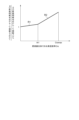
- FIG. 6A is a graph showing an example of the relationship between the hydrogen mixing ratios Crm, Crp of each combustion burner and the hydrogen mixing ratio Cro of the entire combustor 4 during rated operation.
- FIG. 6B is a graph showing an example of the relationship between the ratio (Crp/Crm) of the hydrogen mixing ratio Crp in the pilot combustion burner 50 to the hydrogen mixing ratio Crm in the main combustion burner 60 and the hydrogen mixing ratio Cro in the entire combustor 4, when the hydrogen mixing ratios Crm, Crp of each combustion burner and the hydrogen mixing ratio Cro in the entire combustor 4 have the relationship shown in FIG. 6A.
- FIG. 6A is a graph showing an example of the relationship between the hydrogen mixing ratios Crm, Crp of each combustion burner and the hydrogen mixing ratio Cro of the entire combustor 4 during rated operation.
- FIG. 6B is a graph showing an example of the relationship between the ratio (Crp/Crm) of the hydrogen mixing ratio Crp in the pilot combustion burner 50 to the hydrogen mixing ratio Crm in
- FIG. 7A is a graph showing another example of the relationship between the hydrogen mixing ratios Crm, Crp of the combustion burners and the hydrogen mixing ratio Cro of the entire combustor 4 during rated operation.
- FIG. 7B is a graph showing an example of the relationship between the ratio (Crp/Crm) of the hydrogen mixing ratio Crp in the pilot combustion burner 50 to the hydrogen mixing ratio Crm in the main combustion burner 60 and the hydrogen mixing ratio Cro in the entire combustor 4, when the hydrogen mixing ratios Crm, Crp of each combustion burner and the hydrogen mixing ratio Cro in the entire combustor 4 have the relationship shown in FIG. 7A.
- FIG. 7A is a graph showing another example of the relationship between the hydrogen mixing ratios Crm, Crp of the combustion burners and the hydrogen mixing ratio Cro of the entire combustor 4 during rated operation.
- FIG. 7B is a graph showing an example of the relationship between the ratio (Crp/Crm) of the hydrogen mixing ratio Crp in the pilot combustion burner 50 to the hydrogen mixing ratio Cr
- FIG. 8A is a graph showing yet another example of the relationship between the hydrogen mixing ratios Crm, Crp of the combustion burners and the hydrogen mixing ratio Cro of the entire combustor 4 during rated operation.
- FIG. 8B is a graph showing an example of the relationship between the ratio (Crp/Crm) of the hydrogen mixing ratio Crp in the pilot combustion burner 50 to the hydrogen mixing ratio Crm in the main combustion burner 60 and the hydrogen mixing ratio Cro in the entire combustor 4, when the hydrogen mixing ratios Crm, Crp of each combustion burner and the hydrogen mixing ratio Cro in the entire combustor 4 have the relationship shown in FIG. 8A.
- FIG. 8A is a graph showing yet another example of the relationship between the hydrogen mixing ratios Crm, Crp of the combustion burners and the hydrogen mixing ratio Cro of the entire combustor 4 during rated operation.
- FIG. 8B is a graph showing an example of the relationship between the ratio (Crp/Crm) of the hydrogen mixing ratio Crp in the pilot combustion burner 50 to the hydrogen mixing
- FIG. 9A is a graph showing an example of the relationship between the hydrogen mixing ratios Crm, Crp of each combustion burner and the hydrogen mixing ratio Cro of the entire combustor 4 during partial load operation.
- FIG. 9B is a graph showing an example of the relationship between the ratio (Crp/Crm) of the hydrogen mixing ratio Crp in the pilot combustion burner 50 to the hydrogen mixing ratio Crm in the main combustion burner 60 and the hydrogen mixing ratio Cro in the entire combustor 4, when the hydrogen mixing ratios Crm, Crp of each combustion burner and the hydrogen mixing ratio Cro in the entire combustor 4 have the relationship shown in FIG. 9A.
- the hydrogen mixing ratios Crm, Crp of each combustion burner may be gradually increased while maintaining the same value as the hydrogen mixing ratio Cro of the entire combustor 4 increases.
- Such changes in the hydrogen mixing ratios Crm, Crp of each combustion burner can be achieved, for example, by gradually opening the third adjustment valve 243, which adjusts the amount of hydrogen fuel FH supplied to the main combustion burner 60 and the pilot combustion burner 50, while keeping the fourth adjustment valve 244, which adjusts the amount of hydrogen fuel FH supplied to the pilot combustion burner 50 shown in Figure 5, closed.
- the combustion control device 140 may send a control signal to the third control valve 243 so that the third control valve 243 operates in this manner.
- the hydrogen combustion ratio Crp of the pilot combustion burner 50 may be gradually increased to increase the hydrogen combustion ratio Cro of the entire combustor 4.
- the hydrogen combustion ratio Crp of the pilot combustion burner 50 may be gradually increased to increase the hydrogen combustion ratio Cro of the entire combustor 4.
- Such a transition of the hydrogen mixing ratios Crm, Crp of each combustion burner can be achieved, for example, by gradually closing the second control valve 242 of the second supply line 212 and gradually opening the fourth control valve 244 while keeping the opening degree of the third control valve 243 shown in FIG. 5 fixed. Additionally, the combustion control device 140 may send control signals to the second and fourth control valves 242, 244 to cause them to operate in this manner.
- the upper limit Crpmax of the hydrogen mixing ratio Crp in the pilot combustion burner 50 may be 100% as shown in FIG. 6A and in FIGS. 7A, 8A, and 9A described below.
- the hydrogen combustion ratio Cro in the entire combustor 4 is at the value th1 or the value th3 described below.
- the hydrogen combustion ratio Cro is equal to or less than the value th1 or the value th3, this is called low hydrogen combustion ratio operation, and when the hydrogen combustion ratio Cro exceeds the value th1 or the value th3, this is called high hydrogen combustion ratio operation.
- the above ratio (Crp/Crm) during low hydrogen fuel ratio operation is referred to as the first ratio R1
- the above ratio (Crp/Crm) during high hydrogen fuel ratio operation is referred to as the second ratio R2.
- the fourth control valve 244 for adjusting the supply amount of hydrogen fuel FH to the pilot combustion burner 50 is kept closed until the hydrogen mixing ratio Crm in the main combustion burner 60 reaches the upper limit value Crmmax.
- the fourth control valve 244 may start to be opened before the hydrogen mixing ratio Crm in the main combustion burner 60 reaches the upper limit value Crmmax.
- 7A and 7B is an example of a case where, in the process of increasing the hydrogen mixing ratio Cro in the entire combustor 4, the fourth control valve 244 starts to be opened when the hydrogen mixing ratio Crm in the main combustion burner 60 reaches a value th2 which is smaller than the value th1 (th2 ⁇ th1).
- the hydrogen mixing ratio Crp in the pilot combustion burner 50 is greater than the hydrogen mixing ratio Crm in the main combustion burner 60 until the hydrogen mixing ratio Cro in the entire combustor 4 reaches a value th1, and the difference between the two gradually increases as the hydrogen mixing ratio Cro in the entire combustor 4 increases.
- the hydrogen mixing ratio Crm in the main combustion burner 60 becomes the upper limit value Crmmax, and the hydrogen mixing ratio Crp in the pilot combustion burner 50 gradually increases. That is, in the example shown in FIG. 7A, in the process of increasing the hydrogen mixing ratio Cro in the entire combustor 4, after the hydrogen mixing ratio Cro in the entire combustor 4 reaches the value th1, for example, while keeping the opening of the third control valve 243 shown in FIG. 5 fixed, the second control valve 242 of the second supply line 212 may be gradually closed and the fourth control valve 244 may be gradually opened.
- the fourth control valve 244 for adjusting the supply amount of hydrogen fuel FH to the pilot combustion burner 50 is kept closed until the hydrogen mixing ratio Cro in the entire combustor 4 reaches the value th2.
- the fourth control valve 244 may be started to be opened at the same time as the third control valve 243 is started to be opened.
- the example shown in Figures 8A and 8B is an example of a case where the third control valve 243 and the fourth control valve 244 are started to be opened at the same time in the process of increasing the hydrogen mixing ratio Cro in the entire combustor 4.
- the hydrogen combustion ratio Crp in the pilot combustion burner 50 is greater than the hydrogen combustion ratio Crm in the main combustion burner 60 until the hydrogen combustion ratio Cro in the entire combustor 4 reaches a value th1, and the difference between the two gradually increases as the hydrogen combustion ratio Cro in the entire combustor 4 increases.
- the upper limit value Crpmax of the hydrogen mixing ratio Crp in the pilot combustion burner 50 is 100% during rated operation as shown in FIGS. 6A, 7A, and 8A, so there is no room to increase the upper limit value Crpmax of the hydrogen mixing ratio Crp in the pilot combustion burner 50.
- the upper limit value Crmmax of the hydrogen mixing ratio Crm in the main combustion burner 60 during partial load operation is made larger than that during rated operation, so that the maximum value Cromax of the hydrogen mixing ratio Cro in the entire combustor 4 during partial load operation is made larger than that during rated operation.
- the upper limit Crmmax of the hydrogen mixing ratio Crm in the main combustion burner 60 during partial load operation is made larger than that during rated operation.
- the hydrogen mixing ratios Crm, Crp of each combustion burner may be set to gradually increase while maintaining the same value as the hydrogen mixing ratio Cro of the entire combustor 4 increases.
- the hydrogen mixing ratio Crp of the pilot combustion burner 50 may be gradually increased to increase the hydrogen mixing ratio Cro of the entire combustor 4. That is, during high hydrogen mixing ratio operation in which the hydrogen mixing ratio is higher than during low hydrogen mixing ratio operation, the hydrogen mixing ratio Crp of the pilot combustion burner 50 may be gradually increased to increase the hydrogen mixing ratio Cro of the entire combustor 4. In the example shown in FIG.
- the second control valve 242 in the second supply line 212 may be gradually closed and the fourth control valve 244 may be gradually opened.
- the hydrogen mixing ratios Crm, Crp of each combustion burner when the hydrogen mixing ratios Crm, Crp of each combustion burner are changed, as shown in FIG. 9B , when the value of the hydrogen mixing ratio Cro is equal to or less than the value th3 (during low hydrogen mixing ratio operation), the ratio (Crp/Crm) of the hydrogen mixing ratio Crp in the pilot combustion burner 50 to the hydrogen mixing ratio Crm in the main combustion burner 60 becomes 1.
- the hydrogen mixing ratios Crm, Crp of each combustion burner are changed, as shown in FIG. 9B, when the hydrogen mixing ratio Cro exceeds the value th3 (during high hydrogen mixing ratio operation), the ratio (Crp/Crm) exceeds 1 and gradually increases as the hydrogen mixing ratio Cro increases.
- the upper limit value Crmmax of the hydrogen mixing ratio Crm in the main combustion burner 60 may be set to be larger as the combustion gas temperature T1T at the inlet of the gas turbine becomes lower.
- a method for operating a gas turbine is a method for operating a gas turbine 1 including a combustor 4 having a main nozzle 64 and a pilot nozzle 54, and capable of using hydrogen and a fuel other than hydrogen as fuel.
- the ratio (Crp/Crm) of the hydrogen combustion ratio Crp of the fuel F injected from the pilot nozzle 54 to the hydrogen combustion ratio Crm of the fuel F injected from the main nozzle 64 is larger in a second ratio R2 during high hydrogen combustion ratio operation in which the hydrogen combustion ratio Cro in the entire combustor 4 is higher than in low hydrogen combustion ratio operation, compared to a first ratio R1 during low hydrogen combustion ratio operation.
- the risk of backfire can be reduced by making the hydrogen mixing ratio Crp of the fuel F injected from the pilot combustion burner 50 higher than the hydrogen mixing ratio Crm of the fuel F injected from the main combustion burner 60.
- the gas turbine when the pilot combustion burner 50 is less likely to cause flashback than the main combustion burner 60, the gas turbine can be operated at a high hydrogen mixing ratio Cro while suppressing flashback.
- the second ratio R2 may be increased as the hydrogen mixing ratio of the fuel F supplied to the combustor 4 (the hydrogen mixing ratio Cro in the entire combustor 4) increases.
- the hydrogen mixing ratio Crm of the main combustion burner 60 is suppressed to suppress flashback, while the hydrogen mixing ratio Crp of the pilot combustion burner 50 is increased, thereby making it possible to increase the hydrogen mixing ratio Cro of the entire combustor 4.
- the hydrogen mixing ratio Crp of the fuel F injected from the pilot combustion burner 50 increases as the hydrogen mixing ratio of the fuel F supplied to the combustor 4 (the hydrogen mixing ratio Cro in the entire combustor 4) increases.
- the hydrogen mixing ratio Crp of the pilot combustion burner 50 by increasing the hydrogen mixing ratio Crp of the pilot combustion burner 50, it is possible to increase the hydrogen mixing ratio Cro in the entire combustor 4 while suppressing flashback.
- the rate of increase in the hydrogen mixing ratio Crp of the fuel F injected from the pilot combustion burner 50 relative to the rate of increase in the hydrogen mixing ratio of the fuel F supplied to the combustor 4 may be greater than the rate of increase in the hydrogen mixing ratio Crm of the fuel F injected from the main combustion burner 60 relative to the rate of increase in the hydrogen mixing ratio of the fuel F supplied to the combustor 4 (the hydrogen mixing ratio Cro in the entire combustor 4).
- the hydrogen mixing ratio Crm of the fuel F injected from the main combustion burner 60 may be a constant value regardless of the hydrogen mixing ratio of the fuel F supplied to the combustor 4 (the hydrogen mixing ratio Cro in the entire combustor 4).
- the hydrogen mixing ratio Crm of the main combustion burner 60 is kept constant to suppress flashback, while the hydrogen mixing ratio Crp of the pilot combustion burner 50 is increased, making it possible to increase the hydrogen mixing ratio Cro of the entire combustor 4.
- the upper limit value Crpmax of the hydrogen mixing ratio Crp of the fuel F injected from the pilot combustion burner 50 may be 100%.
- the hydrogen mixing ratio Crp of the pilot combustion burner 50 can be set to 100% while suppressing flashback in the combustor 4, and the hydrogen mixing ratio Cor in the entire combustor 4 can be increased.
- the first ratio R1 may be 1 during at least a portion of the low hydrogen co-firing ratio operation.
- the hydrogen mixing ratio Crm of the fuel F injected from the main combustion burner 60 and the hydrogen mixing ratio Crp of the fuel F injected from the pilot combustion burner 50 are equal, so that the supply system 200 for the fuel F to the main combustion burner 60 and the pilot combustion burner 50 can be shared as shown in FIG. 5, and therefore the supply system 200 for the fuel F can be simplified.
- the upper limit Crmmax of the hydrogen mixing ratio Crm of the fuel F injected from the main combustion burner 60 is preferably greater during partial load operation of the gas turbine 1 than during rated operation.
- the maximum value Cromax of the hydrogen mixing ratio Cro in the entire combustor 4 during partial load operation can be made larger than that during rated operation.
- the upper limit Crmmax of the hydrogen mixing ratio Crm of the main combustion burner 60 during partial load operation can be made larger than that during rated operation, so that the maximum value Cromax of the total hydrogen mixing ratio (hydrogen mixing ratio Cro in the entire combustor 4) during partial load operation can be made larger than that during rated operation.
- the hydrogen mixing ratio Cro in the entire combustor 4 can be increased.
- the combustor 4 may include a main combustion burner 60 having a main nozzle 64 and a pilot combustion burner 50 having a pilot nozzle 54.
- the main combustion burner 60 may be a premixed combustion type burner
- the pilot combustion burner 50 may be a diffusion combustion type burner.
- the pilot combustion burner 50 may have a water flow path and be configured to inject water. This makes it possible to suppress the flame temperature, thereby suppressing NOx and the metal temperature of the pilot combustion burner 50 (cone portion 56b).
- the present disclosure is not limited to the above-described embodiments, and includes modifications to the above-described embodiments and appropriate combinations of these modifications.
- the ratio (Crp/Crm) of the hydrogen mixing ratio Crp in the pilot combustion burner 50 to the hydrogen mixing ratio Crm in the main combustion burner 60 may be less than 1.
- a method of operating a gas turbine 1 is a method of operating a gas turbine 1 including a combustor 4 having a main nozzle 64 and a pilot nozzle 54, and capable of using hydrogen and a fuel other than hydrogen as fuel.
- a ratio (Crp/Crm) of the hydrogen mixing ratio (Crp) of the fuel F injected from the pilot nozzle 54 to the hydrogen mixing ratio (Crm) of the fuel F injected from the main nozzle 64 is greater in a second ratio R2 during high hydrogen mixing ratio operation in which the hydrogen mixing ratio (Cro) is higher than in low hydrogen mixing ratio operation, compared to a first ratio R1 during low hydrogen mixing ratio operation.
- the risk of flashback can be reduced by making the hydrogen mixing ratio (Crp) of the fuel F injected from the pilot nozzle 54 higher than the hydrogen mixing ratio (Crm) of the fuel F injected from the main nozzle 64.
- the pilot nozzle 54 is less likely to cause flame backflow than the main nozzle 64, it is possible to operate at a high hydrogen co-firing ratio (Cro) while suppressing backfire.
- the second ratio R2 may be increased as the hydrogen mixing ratio (Cro) of the fuel F supplied to the combustor 4 increases.
- the hydrogen combustion ratio (Crm) of the main nozzle 64 is suppressed to suppress flashback, while the hydrogen combustion ratio (Crp) of the pilot nozzle 54 is increased, thereby increasing the hydrogen combustion ratio Cro of the entire combustor 4.
- the hydrogen mixing ratio (Crp) of the fuel F injected from the pilot nozzle 54 may be increased as the hydrogen mixing ratio (Cro) of the fuel F supplied to the combustor 4 increases.
- the hydrogen combustion ratio (Crp) of the pilot nozzle 54 can be increased to suppress flashback while increasing the hydrogen combustion ratio Cro in the entire combustor 4.
- the rate of increase in the hydrogen mixing ratio (Crp) of the fuel F injected from the pilot nozzle 54 relative to the rate of increase in the hydrogen mixing ratio (Cro) of the fuel F supplied to the combustor 4 may be greater than the rate of increase in the hydrogen mixing ratio (Crm) of the fuel F injected from the main nozzle 64 relative to the rate of increase in the hydrogen mixing ratio (Cro) of the fuel F supplied to the combustor 4.
- the hydrogen combustion ratio (Crm) of the main nozzle 64 is suppressed to suppress flashback, while the hydrogen combustion ratio (Crp) of the pilot nozzle 54 is increased, thereby increasing the hydrogen combustion ratio Cro of the entire combustor 4.
- the hydrogen mixing ratio (Crm) of the fuel F injected from the main nozzle 64 may be a constant value regardless of the hydrogen mixing ratio (Cro) of the fuel F supplied to the combustor 4.
- the hydrogen combustion ratio (Crm) of the main nozzle 64 is kept constant to suppress flashback, while the hydrogen combustion ratio (Crp) of the pilot nozzle 54 is increased, thereby making it possible to increase the hydrogen combustion ratio Cro of the entire combustor 4.
- the upper limit of the hydrogen mixing ratio (Crp) of the fuel F injected from the pilot nozzle 54 may be 100%.
- the first ratio R1 may be 1 during at least a portion of the low hydrogen co-firing ratio operation.
- the hydrogen mixing ratio (Crm) of the fuel F injected from the main nozzle 64 is equal to the hydrogen mixing ratio (Crp) of the fuel F injected from the pilot nozzle 54, so the fuel F supply system 200 for the main nozzle 64 and the pilot nozzle 54 can be shared, and the fuel F supply system 200 can be simplified.
- the upper limit (Crmmax) of the hydrogen mixing ratio (Crm) of the fuel F injected from the main nozzle 64 may be greater during partial load operation of the gas turbine 1 than during rated operation.
- the risk of backfiring of the hydrogen fuel FH is smaller during partial load operation of the gas turbine 1 than during rated operation, so the maximum value Cromax of the hydrogen mixing ratio Cro in the entire combustor 4 during partial load operation can be made larger than during rated operation.
- the maximum value (Cromax) of the total hydrogen mixing ratio (Cro) during partial load operation can be made larger than during rated operation.
- the combustor 4 may include a main combustion burner 60 having a main nozzle 64 and a pilot combustion burner 50 having a pilot nozzle 54.
- the main combustion burner 60 may be a premixed combustion type burner
- the pilot combustion burner 50 may be a diffusion combustion type burner.
- the upper limit (Crpmax) of the hydrogen mixing ratio (Crp) of the pilot combustion burner 50 can be increased, and the total hydrogen mixing ratio (Cro) can be increased.
- the pilot nozzle 54 may have a water flow path and be configured to be able to inject water.
Landscapes
- Engineering & Computer Science (AREA)
- Chemical & Material Sciences (AREA)
- Combustion & Propulsion (AREA)
- Mechanical Engineering (AREA)
- General Engineering & Computer Science (AREA)
Abstract
一実施形態に係るガスタービンの運転方法は、メインノズルとパイロットノズルとを有し、水素と、水素以外の燃料とを燃料として使用可能な燃焼器を備えたガスタービンの運転方法である。一実施形態に係るガスタービンの運転方法では、メインノズルから噴射する燃料の水素混焼率に対するパイロットノズルから噴射する燃料の水素混焼率の比は、低水素混焼率運転時の第1比と比べて、低水素混焼率運転時よりも水素混焼率が高い高水素混焼率運転時の第2比の方が大きい。
Description
本開示は、ガスタービンの運転方法に関する。
本願は、2022年12月1日に日本国特許庁に出願された特願2022-192566号に基づき優先権を主張し、その内容をここに援用する。
本願は、2022年12月1日に日本国特許庁に出願された特願2022-192566号に基づき優先権を主張し、その内容をここに援用する。
例えば火力発電プラントでは、地球温暖化の原因となる二酸化炭素(CO2)の排出量を削減する手段として、発電効率の向上や化石燃料以外の水素などの燃料を積極的に利用することが検討されている(例えば特許文献1参照)。
二酸化炭素の排出量を削減するためには、水素の混焼率を高めることが望ましい。しかし、水素は着火エネルギーが小さく、燃焼速度が速いため、水素の混焼率を高めると、火炎の逆流等を生じる可能性が高まってしまう。
本開示の少なくとも一実施形態は、上述の事情に鑑みて、ガスタービンの運転に際して、火炎の逆流等を抑制しつつ水素混焼率を高めることを目的とする。
(1)本開示の少なくとも一実施形態に係るガスタービンの運転方法は、
メインノズルとパイロットノズルとを有し、水素と、水素以外の燃料とを燃料として使用可能な燃焼器を備えたガスタービンの運転方法であって、
前記メインノズルから噴射する燃料の水素混焼率に対する前記パイロットノズルから噴射する燃料の水素混焼率の比は、低水素混焼率運転時の第1比と比べて、前記低水素混焼率運転時よりも水素混焼率が高い高水素混焼率運転時の第2比の方が大きい。
メインノズルとパイロットノズルとを有し、水素と、水素以外の燃料とを燃料として使用可能な燃焼器を備えたガスタービンの運転方法であって、
前記メインノズルから噴射する燃料の水素混焼率に対する前記パイロットノズルから噴射する燃料の水素混焼率の比は、低水素混焼率運転時の第1比と比べて、前記低水素混焼率運転時よりも水素混焼率が高い高水素混焼率運転時の第2比の方が大きい。
本開示の少なくとも一実施形態によれば、ガスタービンの運転に際して、火炎の逆流等を抑制しつつ水素混焼率を高められる。
以下、添付図面を参照して本開示の幾つかの実施形態について説明する。ただし、実施形態として記載されている又は図面に示されている構成部品の寸法、材質、形状、その相対的配置等は、本開示の範囲をこれに限定する趣旨ではなく、単なる説明例にすぎない。
例えば、「ある方向に」、「ある方向に沿って」、「平行」、「直交」、「中心」、「同心」或いは「同軸」等の相対的或いは絶対的な配置を表す表現は、厳密にそのような配置を表すのみならず、公差、若しくは、同じ機能が得られる程度の角度や距離をもって相対的に変位している状態も表すものとする。
例えば、「同一」、「等しい」及び「均質」等の物事が等しい状態であることを表す表現は、厳密に等しい状態を表すのみならず、公差、若しくは、同じ機能が得られる程度の差が存在している状態も表すものとする。
例えば、四角形状や円筒形状等の形状を表す表現は、幾何学的に厳密な意味での四角形状や円筒形状等の形状を表すのみならず、同じ効果が得られる範囲で、凹凸部や面取り部等を含む形状も表すものとする。
一方、一の構成要素を「備える」、「具える」、「具備する」、「含む」、又は、「有する」という表現は、他の構成要素の存在を除外する排他的な表現ではない。
(ガスタービン1について)
図1は、幾つかの実施形態に係るガスタービン1を示す概略構成図である。
幾つかの実施形態に係るガスタービンの運転方法の適用先の一例であるガスタービンについて、図1を参照して説明する。
図1は、幾つかの実施形態に係るガスタービン1を示す概略構成図である。
幾つかの実施形態に係るガスタービンの運転方法の適用先の一例であるガスタービンについて、図1を参照して説明する。
図1に示すように、幾つかの実施形態に係るガスタービンの運転方法によって運転されるガスタービン1は、酸化剤としての圧縮空気を生成するための圧縮機2と、圧縮空気及び燃料を用いて燃焼ガスを発生させるためのガスタービン燃焼器4と、燃焼ガスによって回転駆動されるように構成されたタービン6と、を備える。発電用のガスタービン1の場合、タービン6には不図示の発電機が連結され、タービン6の回転エネルギーによって発電が行われるようになっている。以下の説明では、ガスタービン燃焼器4のことを単に燃焼器4とも称する。
幾つかの実施形態に係るガスタービン1における各部位の具体的な構成例について説明する。
幾つかの実施形態に係る圧縮機2は、圧縮機車室10と、圧縮機車室10の入口側に設けられ、空気を取り込むための空気取入口12と、圧縮機車室10及び後述するタービン車室22を共に貫通するように設けられたロータ8と、圧縮機車室10内に配置された各種の翼と、を備える。各種の翼は、空気取入口12側に設けられた入口案内翼14と、圧縮機車室10側に固定された複数の静翼16と、静翼16に対して交互に配列されるようにロータ8に植設された複数の動翼18と、を含む。なお、圧縮機2は、不図示の抽気室等の他の構成要素を備えていてもよい。このような圧縮機2において、空気取入口12から取り込まれた空気は、複数の静翼16及び複数の動翼18を通過して圧縮されることで高温高圧の圧縮空気となる。そして、高温高圧の圧縮空気は圧縮機2から後段の燃焼器4に送られる。
幾つかの実施形態に係る圧縮機2は、圧縮機車室10と、圧縮機車室10の入口側に設けられ、空気を取り込むための空気取入口12と、圧縮機車室10及び後述するタービン車室22を共に貫通するように設けられたロータ8と、圧縮機車室10内に配置された各種の翼と、を備える。各種の翼は、空気取入口12側に設けられた入口案内翼14と、圧縮機車室10側に固定された複数の静翼16と、静翼16に対して交互に配列されるようにロータ8に植設された複数の動翼18と、を含む。なお、圧縮機2は、不図示の抽気室等の他の構成要素を備えていてもよい。このような圧縮機2において、空気取入口12から取り込まれた空気は、複数の静翼16及び複数の動翼18を通過して圧縮されることで高温高圧の圧縮空気となる。そして、高温高圧の圧縮空気は圧縮機2から後段の燃焼器4に送られる。
幾つかの実施形態に係る燃焼器4は、ケーシング20内に配置される。図1に示すように、燃焼器4は、ケーシング20内にロータ8を中心として環状に複数配置されていてもよい。燃焼器4には燃料と圧縮機2で生成された圧縮空気とが供給され、燃料を燃焼させることによって、タービン6の作動流体である燃焼ガスを発生させる。そして、燃焼ガスは燃焼器4から後段のタービン6に送られる。なお、幾つかの実施形態に係る燃焼器4の構成例については後述する。
幾つかの実施形態に係るタービン6は、タービン車室22と、タービン車室22内に配置された各種の翼と、を備える。各種の翼は、タービン車室22側に固定された複数の静翼24と、静翼24に対して交互に配列されるようにロータ8に植設された複数の動翼26と、を含む。なお、タービン6は、出口案内翼等の他の構成要素を備えていてもよい。タービン6においては、燃焼ガスが複数の静翼24及び複数の動翼26を通過することでロータ8が回転駆動する。これにより、ロータ8に連結された発電機が駆動されるようになっている。
タービン車室22の下流側には、排気車室28を介して排気室30が連結されている。タービン6を駆動した後の燃焼ガスは、排気車室28及び排気室30を介して外部へ排出される。
タービン車室22の下流側には、排気車室28を介して排気室30が連結されている。タービン6を駆動した後の燃焼ガスは、排気車室28及び排気室30を介して外部へ排出される。
(燃焼器4について)
図2は、幾つかの実施形態に係る燃焼器4を示す断面図である。図3は、幾つかの実施形態に係る燃焼器4の要部を示す断面図である。図4は、幾つかの実施形態に係る燃焼器4を燃焼器4の軸線方向に沿って下流側から上流側を見たときの各燃料噴射器の配置を模式的に示した図である。
図2、図3及び図4を参照して、幾つかの実施形態に係る燃焼器4の構成について説明する。
図2は、幾つかの実施形態に係る燃焼器4を示す断面図である。図3は、幾つかの実施形態に係る燃焼器4の要部を示す断面図である。図4は、幾つかの実施形態に係る燃焼器4を燃焼器4の軸線方向に沿って下流側から上流側を見たときの各燃料噴射器の配置を模式的に示した図である。
図2、図3及び図4を参照して、幾つかの実施形態に係る燃焼器4の構成について説明する。
図2及び図3に示すように、幾つかの実施形態に係る燃焼器4は、ロータ8を中心として環状に複数配置されている(図1参照)。各燃焼器4は、ケーシング20により画定される燃焼器車室40に設けられた燃焼器ライナ46と、燃焼器ライナ46内にそれぞれ配置された燃料噴射器であるメイン燃焼バーナ60及びパイロット燃焼バーナ50とを含む。
燃焼器4は、ケーシング20の内部において燃焼器ライナ46の内筒47の外周側に設けられた外筒45をさらに含む。内筒47の外周側かつ外筒45の内周側には、圧縮空気が流れる空気通路43が形成される。
なお、燃焼器4は、燃焼ガスをバイパスさせるためのバイパス管(不図示)等の他の構成要素を備えていてもよい。
なお、燃焼器4は、燃焼ガスをバイパスさせるためのバイパス管(不図示)等の他の構成要素を備えていてもよい。
例えば、燃焼器ライナ46は、パイロット燃焼バーナ50及び複数のメイン燃焼バーナ60の周囲に配置される内筒47と、内筒47の先端部に連結された尾筒48と、を有している。すなわち、燃焼器ライナ46は、メイン燃焼バーナ60及びパイロット燃焼バーナ50から噴射された燃料Fが燃焼する燃焼部に相当する。
図3及び図4に示すように、パイロット燃焼バーナ50は、燃焼器ライナ46の中心軸に沿って配置されている。そして、パイロット燃焼バーナ50の外周側を囲むように、複数のメイン燃焼バーナ60が互いに離間して周方向に並んで配置されている。
図3及び図4に示すように、パイロット燃焼バーナ50は、燃焼器ライナ46の中心軸に沿って配置されている。そして、パイロット燃焼バーナ50の外周側を囲むように、複数のメイン燃焼バーナ60が互いに離間して周方向に並んで配置されている。
図3に示すように、パイロット燃焼バーナ50は、燃料ポート52に連結されたパイロットノズル54と、パイロットノズル54を囲むように配置されたパイロットバーナ筒56と、パイロットノズル54の外周に設けられた複数のスワラ(旋回板)58と、を有している。
パイロットノズル54は、燃焼器軸線Acを中心として軸線方向Daに延在している。
ここで、燃焼器軸線Acの延在方向である軸線方向Daの一方側であって燃焼ガスの流れに沿った上流側を上流側とし、他方側であって燃焼ガスの流れに沿った下流側を下流側とする。また、燃焼器軸線Acは、このパイロット燃焼バーナ50のバーナ軸線でもある。
パイロットノズル54は、燃焼器軸線Acを中心として軸線方向Daに延在している。
ここで、燃焼器軸線Acの延在方向である軸線方向Daの一方側であって燃焼ガスの流れに沿った上流側を上流側とし、他方側であって燃焼ガスの流れに沿った下流側を下流側とする。また、燃焼器軸線Acは、このパイロット燃焼バーナ50のバーナ軸線でもある。
パイロットノズル54の下流側端部には、燃料Fを噴射する不図示の噴射孔が形成されている。パイロットノズル54で噴射孔が形成されている位置よりも上流側には、複数の旋回板58が設けられている。各旋回板58は、燃焼器軸線Acを中心として圧縮空気を旋回させるためのものである。各旋回板58は、パイロットノズル54の外周から放射方向成分を含む方向に延びて、パイロットバーナ筒56の内周面に近接している。パイロットバーナ筒56は、パイロットノズル54の外周に位置する本体部56aと、本体部56aの下流側に接続され下流側に向かって次第に拡径されているコーン部56bと、を有する。複数の旋回板58は、パイロットバーナ筒56における本体部56aの内周面に近接している。
パイロットノズル54は、火炎温度を抑制してNOxの抑制とコーン部56bのメタル温度の抑制を図るための不図示の水の流路を有し、水を噴射可能に構成されている。
メイン燃焼バーナ60は、燃料ポート62に連結されたメインノズル64と、メインノズル64を囲むように配置されたメインバーナ筒66と、メインバーナ筒66と燃焼器ライナ46(例えば内筒47)をつなぐ延長管65と、メインノズル64の外周に設けられたスワラ(旋回板)70と、を有している。
メインノズル64は、燃焼器軸線Acと平行なバーナ軸線Abを中心として軸線方向Daに延在する棒状のノズルである。なお、メイン燃焼バーナ60のバーナ軸線Abは、燃焼器軸線Acと平行であるため、燃焼器軸線Acに関する軸線方向Daと、バーナ軸線Abに関する軸線方向Daとは同じ方向である。また、燃焼器軸線Acに関する軸線方向Daの上流側は、バーナ軸線Abに関する軸線方向Daの上流側であり、燃焼器軸線Acに関する軸線方向Daの下流側は、バーナ軸線Abに関する軸線方向Daの下流側である。
メインノズル64の軸線方向Daにおける中間部には、燃料Fを噴射する噴射孔が形成されている。メインノズル64で噴射孔が形成されている位置近傍には、複数の旋回板70が設けられている。各旋回板70は、バーナ軸線Abを中心として圧縮空気を旋回させるためのものである。各旋回板70は、メインノズル64の外周から放射方向成分を含む方向に延びて、メインバーナ筒66の内周面に近接している。メインバーナ筒66は、メインノズル64の外周に位置している。
上記構成を有する燃焼器4において、圧縮機2で生成された圧縮空気は車室入口40aから燃焼器車室40内に供給され、さらに燃焼器車室40から空気通路43を経由してパイロットバーナ筒56及び複数のメインバーナ筒66内に流入する。
パイロット燃焼バーナ50では、パイロットバーナ筒56の下流端から、圧縮空気と共に、パイロットノズル54から噴射された燃料Fが噴出される。この燃料Fは、燃焼器ライナ46内で拡散燃焼又は予混合燃焼する。
すなわち、図2、図3及び図4に示したパイロット燃焼バーナ50は、拡散燃焼式又は予混合燃焼式の燃料噴射器である。
すなわち、図2、図3及び図4に示したパイロット燃焼バーナ50は、拡散燃焼式又は予混合燃焼式の燃料噴射器である。
メイン燃焼バーナ60では、メインバーナ筒66内で圧縮空気とメインノズル64から噴射された燃料Fとが混合して、予混合気体PMが形成される。メイン燃焼バーナ60では、延長管65の下流端から予混合気体PMが噴出される。この予混合気体PM中の燃料Fは、燃焼器ライナ46内で予混合燃焼する。
すなわち、図2、図3及び図4に示したメイン燃焼バーナ60は、予混合燃焼式の燃料噴射器である。
すなわち、図2、図3及び図4に示したメイン燃焼バーナ60は、予混合燃焼式の燃料噴射器である。
なお、旋回板70に燃料Fを噴射する噴射孔を形成し、ここからメインバーナ筒66内に燃料Fを噴射してもよい。この場合、以上で説明した棒状のメインノズル64に相当する部分がハブ棒を成し、メインノズルは、このハブ棒と複数の旋回板70とを有して形成されることになる。ハブ棒内には、外部からの燃料Fが供給され、このハブ棒から旋回板70に燃料Fが供給される。
(燃料Fについて)
幾つかの実施形態に係る燃焼器4では、燃料Fとして、例えば従来の燃料器と同様に天然ガスを用いるとともに、水素を用いることができるように構成されている。なお、以下の説明では、燃料Fとしての天然ガスを天然ガス燃料FN、又は単に天然ガスと称する。同様に、以下の説明では、燃料Fとしての水素を水素燃料FH、又は単に水素と称する。
また、以下の説明では、天然ガス燃料FN、水素燃料FH、及び天然ガス燃料FNと水素燃料FHとの混合燃料FMを特に区別する必要ながない場合、又はこれらの燃料を総称する場合に燃料Fと称することとする。
幾つかの実施形態に係る燃焼器4では、燃料Fとして、例えば従来の燃料器と同様に天然ガスを用いるとともに、水素を用いることができるように構成されている。なお、以下の説明では、燃料Fとしての天然ガスを天然ガス燃料FN、又は単に天然ガスと称する。同様に、以下の説明では、燃料Fとしての水素を水素燃料FH、又は単に水素と称する。
また、以下の説明では、天然ガス燃料FN、水素燃料FH、及び天然ガス燃料FNと水素燃料FHとの混合燃料FMを特に区別する必要ながない場合、又はこれらの燃料を総称する場合に燃料Fと称することとする。
(燃料Fの供給系統について)
図5は、幾つかの実施形態に係る燃焼器4に対する燃料Fの供給系統200の概略を示した図である。幾つかの実施形態に係るガスタービン1は、図5に示す燃料Fの供給系統200を含む。図5に示す燃料Fの供給系統200は、天然ガス燃料FNをメイン燃焼バーナ60に供給するための第1供給ライン211と、天然ガス燃料FNをパイロット燃焼バーナ50に供給するための第2供給ライン212と、水素燃料FHをメイン燃焼バーナ60及びパイロット燃焼バーナ50に供給するための第3供給ライン221と、水素燃料FHをパイロット燃焼バーナ50に供給するための第4供給ライン222とを含む。
図5は、幾つかの実施形態に係る燃焼器4に対する燃料Fの供給系統200の概略を示した図である。幾つかの実施形態に係るガスタービン1は、図5に示す燃料Fの供給系統200を含む。図5に示す燃料Fの供給系統200は、天然ガス燃料FNをメイン燃焼バーナ60に供給するための第1供給ライン211と、天然ガス燃料FNをパイロット燃焼バーナ50に供給するための第2供給ライン212と、水素燃料FHをメイン燃焼バーナ60及びパイロット燃焼バーナ50に供給するための第3供給ライン221と、水素燃料FHをパイロット燃焼バーナ50に供給するための第4供給ライン222とを含む。
天然ガス燃料FNは、天然ガス燃料FNの供給源201から天然ガス供給ライン210を介して供給される。第1供給ライン211と第2供給ライン212とは、分岐部231で分岐している。
第1供給ライン211には、メイン燃焼バーナ60への燃料Fの供給量を調整するための第1調節弁241が設けられている。第1供給ライン211の下流端は、メイン燃焼バーナ60のメインノズル64が連結されている燃料ポート62に接続されている。
第2供給ライン212には、パイロット燃焼バーナ50への燃料Fの供給量を調整するための第2調節弁242が設けられている。第2供給ライン212の下流端は、パイロット燃焼バーナ50のパイロットノズル54が連結されている燃料ポート52に接続されている。
第1供給ライン211には、メイン燃焼バーナ60への燃料Fの供給量を調整するための第1調節弁241が設けられている。第1供給ライン211の下流端は、メイン燃焼バーナ60のメインノズル64が連結されている燃料ポート62に接続されている。
第2供給ライン212には、パイロット燃焼バーナ50への燃料Fの供給量を調整するための第2調節弁242が設けられている。第2供給ライン212の下流端は、パイロット燃焼バーナ50のパイロットノズル54が連結されている燃料ポート52に接続されている。
水素燃料FHは、水素燃料FHの供給源202から水素供給ライン220を介して供給される。第3供給ライン221と第4供給ライン222とは、分岐部232で分岐している。
第3供給ライン221には、メイン燃焼バーナ60及びパイロット燃焼バーナ50への水素燃料FHの供給量を調整するための第3調節弁243が設けられている。第3供給ライン221の下流端は、天然ガス供給ライン210における分岐部231よりも上流側の合流部233で天然ガス供給ライン210に接続されている。
すなわち、第3調節弁243は、天然ガス供給ライン210を流れる天然ガス燃料FNに水素燃料FHを添加する添加量を調節するための調節弁である。
第3供給ライン221には、メイン燃焼バーナ60及びパイロット燃焼バーナ50への水素燃料FHの供給量を調整するための第3調節弁243が設けられている。第3供給ライン221の下流端は、天然ガス供給ライン210における分岐部231よりも上流側の合流部233で天然ガス供給ライン210に接続されている。
すなわち、第3調節弁243は、天然ガス供給ライン210を流れる天然ガス燃料FNに水素燃料FHを添加する添加量を調節するための調節弁である。
第4供給ライン222には、パイロット燃焼バーナ50への水素燃料FHの供給量を調整するための第4調節弁244が設けられている。第4供給ライン222の下流端は、第2供給ライン212における第2調節弁242よりも下流側の合流部234で第2供給ライン212に接続されている。
すなわち、第4調節弁244は、第2供給ライン212を流れる天然ガス燃料FN、又は、天然ガス燃料FNと水素燃料FHとの混合燃料FMに水素燃料FHを添加する添加量を調節することができる調節弁である。なお、後述するように、第2調節弁242を閉じ、第4調節弁244を開くことで、水素燃料FHだけをパイロット燃焼バーナ50へ供給することができる。
すなわち、第4調節弁244は、第2供給ライン212を流れる天然ガス燃料FN、又は、天然ガス燃料FNと水素燃料FHとの混合燃料FMに水素燃料FHを添加する添加量を調節することができる調節弁である。なお、後述するように、第2調節弁242を閉じ、第4調節弁244を開くことで、水素燃料FHだけをパイロット燃焼バーナ50へ供給することができる。
このように構成される燃料Fの供給系統200では、第1調節弁241、第2調節弁242、第3調節弁243、及び第4調節弁244の開度を調節することで、メイン燃焼バーナ60及びパイロット燃焼バーナ50における、噴射する燃料Fにおける水素燃料FHの割合である水素混焼率(カロリー比)を調節できる。
幾つかの実施形態に係る燃焼器4における水素混焼率の制御については、後で詳述する。
幾つかの実施形態に係る燃焼器4における水素混焼率の制御については、後で詳述する。
第1調節弁241、第2調節弁242、第3調節弁243、及び第4調節弁244は、これら各調節弁を制御可能に構成されたコントローラによって制御される。幾つかの実施形態では、このコントローラは、ガスタービン1の燃焼制御装置140によって実現される。
燃焼制御装置140の各処理機能はソフトウェア(コンピュータプログラム)で構成され、コンピュータで実行されるが、これに限定するものではなく、ハードウェアで構成してもよい。
燃焼制御装置140の各処理機能はソフトウェア(コンピュータプログラム)で構成され、コンピュータで実行されるが、これに限定するものではなく、ハードウェアで構成してもよい。
(水の供給について)
幾つかの実施形態に係るガスタービン1は、パイロット燃焼バーナ50へ冷却用の水を供給するための水供給ライン215を備えている。詳細な説明は省略するが、冷却用の水を供給することで、パイロット燃焼バーナ50での水素混焼率を高くしたときに上昇する火炎温度が抑制されるので、NOxの発生が抑制されるとともに、パイロット燃焼バーナ50のコーン部56bのメタル温度を抑制できる。
冷却用の水は、水の供給源205から水供給ライン215を介してパイロット燃焼バーナ50に供給可能とされている。
水供給ライン215には、パイロット燃焼バーナ50への水の供給量を調整するための水供給量調節弁251が設けられている。詳細な説明は省略するが、水供給量調節弁251は、燃焼制御装置140によって制御される。
(水素混焼率の制御について)
例えばガスタービン1のように地球温暖化の原因となる二酸化炭素(CO2)を排出する設備では、二酸化炭素の排出量を削減することが求められている。例えばガスタービン1において二酸化炭素の排出量を削減するためには、水素の混焼率を高めることが望ましい。しかし、水素は着火エネルギーが小さく、燃焼速度が速いため、水素の混焼率を高めると、火炎の逆流等を生じる可能性が高まってしまう。
一方で、火炎の逆流(逆火)のリスクは、燃料噴射器(燃焼バーナ)の構造や燃料噴射器の配置位置等によって異なるため、複数の燃料噴射器においてどの燃料噴射器も逆火のリスクが同じであるとは限らない。具体的には、例えば以下のとおりである。
例えばガスタービン1のように地球温暖化の原因となる二酸化炭素(CO2)を排出する設備では、二酸化炭素の排出量を削減することが求められている。例えばガスタービン1において二酸化炭素の排出量を削減するためには、水素の混焼率を高めることが望ましい。しかし、水素は着火エネルギーが小さく、燃焼速度が速いため、水素の混焼率を高めると、火炎の逆流等を生じる可能性が高まってしまう。
一方で、火炎の逆流(逆火)のリスクは、燃料噴射器(燃焼バーナ)の構造や燃料噴射器の配置位置等によって異なるため、複数の燃料噴射器においてどの燃料噴射器も逆火のリスクが同じであるとは限らない。具体的には、例えば以下のとおりである。
図2、図3及び図4に示す実施形態では、メイン燃焼バーナ60は、予混合燃焼式の燃料噴射器であり、パイロット燃焼バーナ50は、拡散燃焼式又は予混合燃焼式の燃料噴射器である。
一般的に、拡散燃焼式の燃料噴射器は予混合燃焼式の燃料噴射器よりも逆火のリスクが小さい燃料噴射器である。したがって、図2、図3及び図4に示す実施形態では、パイロット燃焼バーナ50は、メイン燃焼バーナ60よりも逆火のリスクが小さい燃料噴射器となる。
一般的に、拡散燃焼式の燃料噴射器は予混合燃焼式の燃料噴射器よりも逆火のリスクが小さい燃料噴射器である。したがって、図2、図3及び図4に示す実施形態では、パイロット燃焼バーナ50は、メイン燃焼バーナ60よりも逆火のリスクが小さい燃料噴射器となる。
なお、一般的に、燃料噴射器が他の複数の燃料噴射器によって周囲を取り囲まれている場合、周囲を取り囲まれている燃料噴射器は、周囲を取り囲んでいる燃料噴射器よりも逆火のリスクが小さくなる。
ここで、図2、図3及び図4に示す実施形態では、メイン燃焼バーナ60は、パイロット燃焼バーナ50の周囲に複数配置されている。したがって、仮に図2、図3及び図4に示す実施形態においてメイン燃焼バーナ60とパイロット燃焼バーナ50とが共に拡散燃焼式又は予混合燃焼式の燃料噴射器である場合のように、メイン燃焼バーナ60とパイロット燃焼バーナ50とで燃料噴射器の構造が同様であれば、パイロット燃焼バーナ50は、メイン燃焼バーナ60よりも逆火のリスクが小さい燃料噴射器となる。
ここで、図2、図3及び図4に示す実施形態では、メイン燃焼バーナ60は、パイロット燃焼バーナ50の周囲に複数配置されている。したがって、仮に図2、図3及び図4に示す実施形態においてメイン燃焼バーナ60とパイロット燃焼バーナ50とが共に拡散燃焼式又は予混合燃焼式の燃料噴射器である場合のように、メイン燃焼バーナ60とパイロット燃焼バーナ50とで燃料噴射器の構造が同様であれば、パイロット燃焼バーナ50は、メイン燃焼バーナ60よりも逆火のリスクが小さい燃料噴射器となる。
そこで、幾つかの実施形態に係るガスタービンの運転方法では、これらを考慮して、ガスタービン1を以下のように運転するようにしている。
上述したように、パイロット燃焼バーナ50がメイン燃焼バーナ60よりも逆火のリスクが小さい燃料噴射器であるので、パイロット燃焼バーナ50での水素混焼率Crpの上限値Crpmaxは、メイン燃焼バーナ60での水素混焼率Crmの上限値Crmmaxよりも大きくなるようにしている。これにより、逆火を抑制しつつ、燃焼器4全体での水素混焼率Croの最大値Cromaxを大きくすることができる。
より具体的には、幾つかの実施形態に係る燃焼器4では、水素混焼率は以下のように制御される。
なお、燃焼器4全体での水素混焼率Croは、1つの燃焼器における、複数のメイン燃焼バーナ60、及びパイロット燃焼バーナ50から噴射するトータルの燃料Fに対するトータルの水素燃料FHの割合をカロリー比で表したものである。
図6Aは、定格運転時における、各燃焼バーナの水素混焼率Crm、Crpと、燃焼器4全体での水素混焼率Croとの関係の一例を示すグラフである。
図6Bは、各燃焼バーナの水素混焼率Crm、Crpと、燃焼器4全体での水素混焼率Croとが図6Aに示す関係であるときの、メイン燃焼バーナ60での水素混焼率Crmに対するパイロット燃焼バーナ50での水素混焼率Crpの比(Crp/Crm)と、燃焼器4全体での水素混焼率Croとの関係の一例を示すグラフである。
図7Aは、定格運転時における、各燃焼バーナの水素混焼率Crm、Crpと、燃焼器4全体での水素混焼率Croとの関係の他の一例を示すグラフである。
図7Bは、各燃焼バーナの水素混焼率Crm、Crpと、燃焼器4全体での水素混焼率Croとが図7Aに示す関係であるときの、メイン燃焼バーナ60での水素混焼率Crmに対するパイロット燃焼バーナ50での水素混焼率Crpの比(Crp/Crm)と、燃焼器4全体での水素混焼率Croとの関係の一例を示すグラフである。
図8Aは、定格運転時における、各燃焼バーナの水素混焼率Crm、Crpと、燃焼器4全体での水素混焼率Croとの関係のさらに他の一例を示すグラフである。
図8Bは、各燃焼バーナの水素混焼率Crm、Crpと、燃焼器4全体での水素混焼率Croとが図8Aに示す関係であるときの、メイン燃焼バーナ60での水素混焼率Crmに対するパイロット燃焼バーナ50での水素混焼率Crpの比(Crp/Crm)と、燃焼器4全体での水素混焼率Croとの関係の一例を示すグラフである。
図9Aは、部分負荷運転時における、各燃焼バーナの水素混焼率Crm、Crpと、燃焼器4全体での水素混焼率Croとの関係の一例を示すグラフである。
図9Bは、各燃焼バーナの水素混焼率Crm、Crpと、燃焼器4全体での水素混焼率Croとが図9Aに示す関係であるときの、メイン燃焼バーナ60での水素混焼率Crmに対するパイロット燃焼バーナ50での水素混焼率Crpの比(Crp/Crm)と、燃焼器4全体での水素混焼率Croとの関係の一例を示すグラフである。
例えばガスタービン1の定格運転時において、天然ガス燃料FNによる専焼(水素混焼率Cro=0%)から水素混焼率Croを徐々に高くしながら混焼する場合について考える。
この場合において、図6Aに示すように、燃焼器4全体での水素混焼率Croが比較的低い低水素混焼率運転時には、燃焼器4全体での水素混焼率Croが増加するにつれて、各燃焼バーナの水素混焼率Crm、Crpは同じ値を取りつつ漸増するようにしてもよい。
このような各燃焼バーナの水素混焼率Crm、Crpの推移は、例えば図5に示したパイロット燃焼バーナ50への水素燃料FHの供給量を調整するための第4調節弁244を閉じたまま、メイン燃焼バーナ60及びパイロット燃焼バーナ50への水素燃料FHの供給量を調整するための第3調節弁243を徐々に開くことで実現できる。
また、燃焼制御装置140が、第3調節弁243がこのように動作するように第3調節弁243に制御信号を送信するとよい。
図6Aに示すように、各燃焼バーナの水素混焼率Crm、Crpを同じ値を取りつつ漸増させた後、メイン燃焼バーナ60での水素混焼率Crmが上限値Crmmaxに達した後は、パイロット燃焼バーナ50での水素混焼率Crpを漸増させることで燃焼器4全体での水素混焼率Croが増加するようにしてもよい。すなわち、低水素混焼率運転時よりも水素混焼率が高い高水素混焼率運転時には、パイロット燃焼バーナ50での水素混焼率Crpを漸増させることで燃焼器4全体での水素混焼率Croが増加するようにしてもよい。
このような各燃焼バーナの水素混焼率Crm、Crpの推移は、例えば図5に示した第3調節弁243の開度を固定したまま、第2供給ライン212の第2調節弁242を徐々に閉じつつ、且つ、第4調節弁244を徐々に開くことで実現できる。
また、燃焼制御装置140が、第2調節弁242及び第4調節弁244がこのように動作するように第2調節弁242及び第4調節弁244に制御信号を送信するとよい。
また、燃焼制御装置140が、第2調節弁242及び第4調節弁244がこのように動作するように第2調節弁242及び第4調節弁244に制御信号を送信するとよい。
なお、パイロット燃焼バーナ50での水素混焼率Crpの上限値Crpmaxは、図6A、及び後述する図7A、図8A、及び図9Aに示すように100%であってもよい。
説明の便宜上、各燃焼バーナの水素混焼率Crm、Crpを同じ値を取りつつ漸増させた後、メイン燃焼バーナ60での水素混焼率Crmが上限値Crmmaxに達したときの燃焼器4全体での水素混焼率Croの値th1、又は後述する値th3を境に、水素混焼率Croの値が値th1又は値th3以下の場合を低水素混焼率運転と称し、水素混焼率Croの値が値th1又は値th3を超えた場合を高水素混焼率運転と称する。
図6Aに示すように、各燃焼バーナの水素混焼率Crm、Crpを変更した場合、図6Bに示すように、水素混焼率Croの値が値th1以下の場合には、メイン燃焼バーナ60での水素混焼率Crmに対するパイロット燃焼バーナ50での水素混焼率Crpの比(Crp/Crm)は、1となる。
図6Aに示すように、各燃焼バーナの水素混焼率Crm、Crpを変更した場合、図6Bに示すように、水素混焼率Croの値が値th1を超える場合には、上記比(Crp/Crm)は、1を超え、水素混焼率Croが大きくなるにつれて漸増する。
図6Aに示すように、各燃焼バーナの水素混焼率Crm、Crpを変更した場合、図6Bに示すように、水素混焼率Croの値が値th1を超える場合には、上記比(Crp/Crm)は、1を超え、水素混焼率Croが大きくなるにつれて漸増する。
以下の説明では、低水素混焼率運転時における上記比(Crp/Crm)を第1比R1と称し、高水素混焼率運転時における上記比(Crp/Crm)を第2比R2と称する。
図6A及び図6Bに示す例では、燃焼器4全体での水素混焼率Croを増加させる過程で、メイン燃焼バーナ60での水素混焼率Crmが上限値Crmmaxに達するまではパイロット燃焼バーナ50への水素燃料FHの供給量を調整するための第4調節弁244を閉じたままとしていた。しかし、燃焼器4全体での水素混焼率Croを増加させる過程で、メイン燃焼バーナ60での水素混焼率Crmが上限値Crmmaxに達する前に第4調節弁244を開き始めてもよい。
図7A及び図7Bに示す例は、燃焼器4全体での水素混焼率Croを増加させる過程で、メイン燃焼バーナ60での水素混焼率Crmが値th1よりも小さい値th2(th2<th1)に達したときから第4調節弁244を開き始めた場合の一例である。
図7A及び図7Bに示す例は、燃焼器4全体での水素混焼率Croを増加させる過程で、メイン燃焼バーナ60での水素混焼率Crmが値th1よりも小さい値th2(th2<th1)に達したときから第4調節弁244を開き始めた場合の一例である。
図7Aに示す例では、燃焼器4全体での水素混焼率Croを増加させる過程で、燃焼器4全体での水素混焼率Croが値th2に達するまでは、燃焼器4全体での水素混焼率Croが増加するにつれて、各燃焼バーナの水素混焼率Crm、Crpは同じ値を取りつつ漸増する。
図7Aに示す例では、燃焼器4全体での水素混焼率Croが値th2に達した後、燃焼器4全体での水素混焼率Croが値th1に達するまでは、パイロット燃焼バーナ50での水素混焼率Crpがメイン燃焼バーナ60での水素混焼率Crmよりも大きな値を取りつつ、燃焼器4全体での水素混焼率Croが大きくなるにつれて両者の差が徐々に大きくなる。
図7Aに示す例では、燃焼器4全体での水素混焼率Croが値th2に達した後、燃焼器4全体での水素混焼率Croが値th1に達するまでは、パイロット燃焼バーナ50での水素混焼率Crpがメイン燃焼バーナ60での水素混焼率Crmよりも大きな値を取りつつ、燃焼器4全体での水素混焼率Croが大きくなるにつれて両者の差が徐々に大きくなる。
図7Aに示す例では、燃焼器4全体での水素混焼率Croを増加させる過程で、燃焼器4全体での水素混焼率Croが値th1に達した後は、メイン燃焼バーナ60での水素混焼率Crmは上限値Crmmaxとなり、パイロット燃焼バーナ50での水素混焼率Crpが漸増する。すなわち、図7Aに示す例では、燃焼器4全体での水素混焼率Croを増加させる過程で、燃焼器4全体での水素混焼率Croが値th1に達した後は、例えば図5に示した第3調節弁243の開度を固定したまま、第2供給ライン212の第2調節弁242を徐々に閉じつつ、且つ、第4調節弁244を徐々に開くとよい。
図7Aに示すように、各燃焼バーナの水素混焼率Crm、Crpを変更した場合、図7Bに示すように、水素混焼率Croの値が値th2以下の場合には、メイン燃焼バーナ60での水素混焼率Crmに対するパイロット燃焼バーナ50での水素混焼率Crpの比(Crp/Crm)は、1となる。
図7Aに示すように、各燃焼バーナの水素混焼率Crm、Crpを変更した場合、図7Bに示すように、水素混焼率Croの値が値th2を超える場合には、上記比(Crp/Crm)は、1を超え、水素混焼率Croが大きくなるにつれて漸増する。
図7Aに示すように、各燃焼バーナの水素混焼率Crm、Crpを変更した場合、図7Bに示すように、水素混焼率Croの値が値th2を超える場合には、上記比(Crp/Crm)は、1を超え、水素混焼率Croが大きくなるにつれて漸増する。
図7A及び図7Bに示す例では、燃焼器4全体での水素混焼率Croを増加させる過程で、燃焼器4全体での水素混焼率Croが値th2に達するまではパイロット燃焼バーナ50への水素燃料FHの供給量を調整するための第4調節弁244を閉じたままとしていた。しかし、燃焼器4全体での水素混焼率Croを増加させる過程で、第3調節弁243を開き始めるのと同時に第4調節弁244を開き始めてもよい。
図8A及び図8Bに示す例は、燃焼器4全体での水素混焼率Croを増加させる過程で、第3調節弁243を開き始めるのと同時に第4調節弁244を開き始めた場合の一例である。
図8A及び図8Bに示す例は、燃焼器4全体での水素混焼率Croを増加させる過程で、第3調節弁243を開き始めるのと同時に第4調節弁244を開き始めた場合の一例である。
図8Aに示す例では、燃焼器4全体での水素混焼率Croを増加させる過程で、燃焼器4全体での水素混焼率Croが値th1に達するまでは、パイロット燃焼バーナ50での水素混焼率Crpがメイン燃焼バーナ60での水素混焼率Crmよりも大きな値を取りつつ、燃焼器4全体での水素混焼率Croが大きくなるにつれて両者の差が徐々に大きくなる。
図8Aに示す例では、燃焼器4全体での水素混焼率Croを増加させる過程で、燃焼器4全体での水素混焼率Croが値th1に達した後は、メイン燃焼バーナ60での水素混焼率Crmは上限値Crmmaxとなり、パイロット燃焼バーナ50での水素混焼率Crpが漸増する。すなわち、図8Aに示す例では、燃焼器4全体での水素混焼率Croを増加させる過程で、燃焼器4全体での水素混焼率Croが値th1に達した後は、例えば図5に示した第3調節弁243の開度を固定したまま、第2供給ライン212の第2調節弁242を徐々に閉じつつ、且つ、第4調節弁244を徐々に開くとよい。
図8Aに示すように、各燃焼バーナの水素混焼率Crm、Crpを変更した場合、図8Bに示すように、メイン燃焼バーナ60での水素混焼率Crmに対するパイロット燃焼バーナ50での水素混焼率Crpの比(Crp/Crm)は、1を超え、燃焼器4全体での水素混焼率Croが大きくなるにつれて漸増する。
(部分負荷運転時の場合)
一般的には、ガスタービン1の負荷が高負荷になるほど燃料Fの供給量が増えるため、逆火のリスクが高まる。逆に、ガスタービン1の部分負荷運転時には定格運転時よりも水素燃料の逆火のリスクは小さくなるので、部分負荷運転時の燃焼器4全体での水素混焼率Croの最大値Cromaxを定格運転時よりも大きくすることができる。
上述したように、パイロット燃焼バーナ50での水素混焼率Crpの上限値Crpmaxは、定格運転時において図6A、図7A、及び図8Aに示すように100%であるため、パイロット燃焼バーナ50での水素混焼率Crpの上限値Crpmaxを引き上げる余地はない。
そこで、幾つかの実施形態に係るガスタービンの運転方法では、図9A及び図9Bに示すように、部分負荷運転時のメイン燃焼バーナ60での水素混焼率Crmの上限値Crmmaxを定格運転時よりも大きくすることで、部分負荷運転時の燃焼器4全体での水素混焼率Croの最大値Cromaxを定格運転時よりも大きくすることしている。
すなわち、幾つかの実施形態に係るガスタービンの運転方法では、図9Aと例えば図6Aとの比較から明らかなように、部分負荷運転時のメイン燃焼バーナ60での水素混焼率Crmの上限値Crmmaxを定格運転時よりも大きくする。
例えばガスタービン1の部分負荷運転時において、天然ガス燃料FNによる専焼(水素混焼率Cro=0%)から水素混焼率Croを徐々に高くしながら混焼する場合について考える。
この場合において、図9Aに示すように、燃焼器4全体での水素混焼率Croが比較的低い低水素混焼率運転時には、燃焼器4全体での水素混焼率Croが増加するにつれて、各燃焼バーナの水素混焼率Crm、Crpは同じ値を取りつつ漸増するようにしてもよい。
この場合において、図9Aに示すように、燃焼器4全体での水素混焼率Croが比較的低い低水素混焼率運転時には、燃焼器4全体での水素混焼率Croが増加するにつれて、各燃焼バーナの水素混焼率Crm、Crpは同じ値を取りつつ漸増するようにしてもよい。
図9Aに示すように、各燃焼バーナの水素混焼率Crm、Crpを同じ値を取りつつ漸増させた後、メイン燃焼バーナ60での水素混焼率Crmが上限値Crmmaxに達した後は、パイロット燃焼バーナ50での水素混焼率Crpを漸増させることで燃焼器4全体での水素混焼率Croが増加するようにしてもよい。すなわち、低水素混焼率運転時よりも水素混焼率が高い高水素混焼率運転時には、パイロット燃焼バーナ50での水素混焼率Crpを漸増させることで燃焼器4全体での水素混焼率Croが増加するようにしてもよい。
図9Aに示す例では、燃焼器4全体での水素混焼率Croを増加させる過程で、燃焼器4全体での水素混焼率Croが値th3に達した後は、例えば図5に示した第3調節弁243の開度を固定したまま、第2供給ライン212の第2調節弁242を徐々に閉じつつ、且つ、第4調節弁244を徐々に開くとよい。
図9Aに示す例では、燃焼器4全体での水素混焼率Croを増加させる過程で、燃焼器4全体での水素混焼率Croが値th3に達した後は、例えば図5に示した第3調節弁243の開度を固定したまま、第2供給ライン212の第2調節弁242を徐々に閉じつつ、且つ、第4調節弁244を徐々に開くとよい。
図9Aに示すように、各燃焼バーナの水素混焼率Crm、Crpを変更した場合、図9Bに示すように、水素混焼率Croの値が値th3以下(低水素混焼率運転時)の場合には、メイン燃焼バーナ60での水素混焼率Crmに対するパイロット燃焼バーナ50での水素混焼率Crpの比(Crp/Crm)は、1となる。
図9Aに示すように、各燃焼バーナの水素混焼率Crm、Crpを変更した場合、図9Bに示すように、水素混焼率Croの値が値th3を超える(高水素混焼率運転時)場合には、上記比(Crp/Crm)は、1を超え、水素混焼率Croが大きくなるにつれて漸増する。
なお、ガスタービン入口燃焼ガス温度T1Tが低くなるほどメイン燃焼バーナ60での水素混焼率Crmの上限値Crmmaxを大きくなるようにしてもよい。
図9Aに示すように、各燃焼バーナの水素混焼率Crm、Crpを変更した場合、図9Bに示すように、水素混焼率Croの値が値th3を超える(高水素混焼率運転時)場合には、上記比(Crp/Crm)は、1を超え、水素混焼率Croが大きくなるにつれて漸増する。
なお、ガスタービン入口燃焼ガス温度T1Tが低くなるほどメイン燃焼バーナ60での水素混焼率Crmの上限値Crmmaxを大きくなるようにしてもよい。
(幾つかの実施形態に係るガスタービンの運転方法のまとめ)
上記各実施形態に記載の内容を以下にまとめる。
幾つかの実施形態に係るガスタービンの運転方法は、メインノズル64とパイロットノズル54とを有し、水素と、水素以外の燃料とを燃料として使用可能な燃焼器4を備えたガスタービン1の運転方法である。メインノズル64から噴射する燃料Fの水素混焼率Crmに対するパイロットノズル54から噴射する燃料Fの水素混焼率Crpの比(Crp/Crm)は、図6B、図7B、図8B、及び図9Bに示すように、低水素混焼率運転時の第1比R1と比べて、低水素混焼率運転時よりも燃焼器4全体での水素混焼率Croが高い高水素混焼率運転時の第2比R2の方が大きい。
上記各実施形態に記載の内容を以下にまとめる。
幾つかの実施形態に係るガスタービンの運転方法は、メインノズル64とパイロットノズル54とを有し、水素と、水素以外の燃料とを燃料として使用可能な燃焼器4を備えたガスタービン1の運転方法である。メインノズル64から噴射する燃料Fの水素混焼率Crmに対するパイロットノズル54から噴射する燃料Fの水素混焼率Crpの比(Crp/Crm)は、図6B、図7B、図8B、及び図9Bに示すように、低水素混焼率運転時の第1比R1と比べて、低水素混焼率運転時よりも燃焼器4全体での水素混焼率Croが高い高水素混焼率運転時の第2比R2の方が大きい。
例えばパイロット燃焼バーナ50の方がメイン燃焼バーナ60よりも火炎の逆流等を起こし難い場合には、燃焼器4全体での水素混焼率Croを高くする場合に、メイン燃焼バーナ60から噴射する燃料Fの水素混焼率Crmよりもパイロット燃焼バーナ50から噴射する燃料Fの水素混焼率Crpを高くすることで、逆火のリスクを低減できる。
幾つかの実施形態に係るガスタービンの運転方法によれば、パイロット燃焼バーナ50の方がメイン燃焼バーナ60よりも逆火を起こし難い場合には、逆火を抑制しつつ高い水素混焼率Croで運転できる。
幾つかの実施形態に係るガスタービンの運転方法によれば、パイロット燃焼バーナ50の方がメイン燃焼バーナ60よりも逆火を起こし難い場合には、逆火を抑制しつつ高い水素混焼率Croで運転できる。
幾つかの実施形態に係るガスタービンの運転方法では、図6B、図7B、図8B、及び図9Bに示すように、第2比R2は、燃焼器4に供給される燃料Fの水素混焼率(燃焼器4全体での水素混焼率Cro)が大きくなるほど大きくなるとよい。
これにより、高水素混焼率運転時にはメイン燃焼バーナ60の水素混焼率Crmを抑制して逆火を抑制しつつパイロット燃焼バーナ50の水素混焼率Crpを大きくすることで燃焼器4全体での水素混焼率Croを大きくすることができる。
これにより、高水素混焼率運転時にはメイン燃焼バーナ60の水素混焼率Crmを抑制して逆火を抑制しつつパイロット燃焼バーナ50の水素混焼率Crpを大きくすることで燃焼器4全体での水素混焼率Croを大きくすることができる。
幾つかの実施形態に係るガスタービンの運転方法では、図6A、図7A、図8A、及び図9Aに示すように、高水素混焼率運転時には燃焼器4に供給される燃料Fの水素混焼率(燃焼器4全体での水素混焼率Cro)が大きくなるほどパイロット燃焼バーナ50から噴射する燃料Fの水素混焼率Crpが大きくなるとよい。
これにより、高水素混焼率運転時にはパイロット燃焼バーナ50の水素混焼率Crpを大きくすることで逆火を抑制しつつ燃焼器4全体での水素混焼率Croを大きくすることができる。
これにより、高水素混焼率運転時にはパイロット燃焼バーナ50の水素混焼率Crpを大きくすることで逆火を抑制しつつ燃焼器4全体での水素混焼率Croを大きくすることができる。
幾つかの実施形態に係るガスタービンの運転方法では、図6A、図7A、図8A、及び図9Aに示すように、高水素混焼率運転時には、燃焼器4に供給される燃料Fの水素混焼率(燃焼器4全体での水素混焼率Cro)の増加率に対するパイロット燃焼バーナ50から噴射する燃料Fの水素混焼率Crpの増加率は、燃焼器4に供給される燃料Fの水素混焼率(燃焼器4全体での水素混焼率Cro)の増加率に対するメイン燃焼バーナ60から噴射する燃料Fの水素混焼率Crmの増加率よりも大きいとよい。
なお、水素混焼率Croの増加率に対する水素混焼率Crpの増加率が水素混焼率Croの増加率に対する水素混焼率Crmの増加率よりも大きいということは、図6A、図7A、図8A、及び図9Aにおいて水素混焼率Crpのグラフ線の傾きが水素混焼率Crmのグラフ線の傾きよりも大きいことと等しい。
幾つかの実施形態に係るガスタービンの運転方法では、図6A、図7A、図8A、及び図9Aに示すように、高水素混焼率運転時、すなわち、水素混焼率Croの値が値th1又は値th3を超えた場合、水素混焼率Crpのグラフ線の傾きが水素混焼率Crmのグラフ線の傾きよりも大きい。
これにより、高水素混焼率運転時にはメイン燃焼バーナ60の水素混焼率Crmを抑制して逆火を抑制しつつパイロット燃焼バーナ50の水素混焼率Crpを大きくすることで燃焼器4全体での水素混焼率Croを大きくすることができる。
幾つかの実施形態に係るガスタービンの運転方法では、図6A、図7A、図8A、及び図9Aに示すように、高水素混焼率運転時には、燃焼器4に供給される燃料Fの水素混焼率(燃焼器4全体での水素混焼率Cro)に関わらずメイン燃焼バーナ60から噴射する燃料Fの水素混焼率Crmは一定の値であってもよい。
これにより、高水素混焼率運転時にはメイン燃焼バーナ60の水素混焼率Crmを一定にして逆火を抑制しつつパイロット燃焼バーナ50の水素混焼率Crpを大きくすることで燃焼器4全体での水素混焼率Croを大きくすることができる。
これにより、高水素混焼率運転時にはメイン燃焼バーナ60の水素混焼率Crmを一定にして逆火を抑制しつつパイロット燃焼バーナ50の水素混焼率Crpを大きくすることで燃焼器4全体での水素混焼率Croを大きくすることができる。
幾つかの実施形態に係るガスタービンの運転方法では、図6A、図7A、図8A、及び図9Aに示すように、パイロット燃焼バーナ50から噴射する燃料Fの水素混焼率Crpの上限値Crpmaxは、100%であるとよい。
これにより、燃焼器4における逆火を抑制しつつパイロット燃焼バーナ50の水素混焼率Crpを100%とすることができ、燃焼器4全体での水素混焼率Corを大きくすることができる。
これにより、燃焼器4における逆火を抑制しつつパイロット燃焼バーナ50の水素混焼率Crpを100%とすることができ、燃焼器4全体での水素混焼率Corを大きくすることができる。
幾つかの実施形態に係るガスタービンの運転方法では、図6A、図7A、及び図9Aに示すように、低水素混焼率運転時の少なくとも一部の期間において、第1比R1は1であるとよい。
これにより、メイン燃焼バーナ60から噴射する燃料Fの水素混焼率Crmとパイロット燃焼バーナ50から噴射する燃料Fの水素混焼率Crpとが等しいので、図5に示すようにメイン燃焼バーナ60とパイロット燃焼バーナ50への燃料Fの供給系統200を共有できるので、燃料Fの供給系統200を簡略化できる。
これにより、メイン燃焼バーナ60から噴射する燃料Fの水素混焼率Crmとパイロット燃焼バーナ50から噴射する燃料Fの水素混焼率Crpとが等しいので、図5に示すようにメイン燃焼バーナ60とパイロット燃焼バーナ50への燃料Fの供給系統200を共有できるので、燃料Fの供給系統200を簡略化できる。
幾つかの実施形態に係るガスタービンの運転方法では、図6A及び図9Aに示すように、メイン燃焼バーナ60から噴射する燃料Fの水素混焼率Crmの上限値Crmmaxは、ガスタービン1の定格運転時よりも部分負荷運転時の方が大きいとよい。
ガスタービン1の部分負荷運転時の方が定格運転時よりも水素燃料FHの逆火のリスクは小さくなるので、部分負荷運転時の燃焼器4全体での水素混焼率Croの最大値Cromaxを定格運転時よりも大きくすることができる。幾つかの実施形態に係るガスタービンの運転方法によれば、部分負荷運転時のメイン燃焼バーナ60の水素混焼率Crmの上限値Crmmaxを定格運転時よりも大きくすることで、部分負荷運転時のトータルの水素混焼率(燃焼器4全体での水素混焼率Cro)の最大値Cromaxを定格運転時よりも大きくすることができる。
また、幾つかの実施形態に係るガスタービンの運転方法によれば、パイロット燃焼バーナ50での水素混焼率Crpが100%となり、それ以上パイロット燃焼バーナ50では水素混焼率Crpを大きくできない場合であっても、燃焼器4全体での水素混焼率Croを大きくすることができる。
また、幾つかの実施形態に係るガスタービンの運転方法によれば、パイロット燃焼バーナ50での水素混焼率Crpが100%となり、それ以上パイロット燃焼バーナ50では水素混焼率Crpを大きくできない場合であっても、燃焼器4全体での水素混焼率Croを大きくすることができる。
幾つかの実施形態に係るガスタービンの運転方法では、図2、図3、及び図4に示すように、燃焼器4は、メインノズル64を有するメイン燃焼バーナ60と、パイロットノズル54を有するパイロット燃焼バーナ50とを備えるとよい。メイン燃焼バーナ60は、予混合燃焼方式のバーナであるとよく、パイロット燃焼バーナ50は、拡散燃焼方式のバーナであるとよい。
これにより、拡散燃焼方式のバーナの方が予混合燃焼方式のバーナよりも逆火リスクが小さいので、パイロット燃焼バーナ50の水素混焼率Crpの上限値を高くすることができ、トータルの水素混焼率(燃焼器4全体での水素混焼率Cro)を大きくできる。
これにより、拡散燃焼方式のバーナの方が予混合燃焼方式のバーナよりも逆火リスクが小さいので、パイロット燃焼バーナ50の水素混焼率Crpの上限値を高くすることができ、トータルの水素混焼率(燃焼器4全体での水素混焼率Cro)を大きくできる。
幾つかの実施形態に係るガスタービンの運転方法では、パイロット燃焼バーナ50は、水の流路を有し、水を噴射可能に構成されているとよい。
これにより、火炎温度を抑制してNOxの抑制とパイロット燃焼バーナ50(コーン部56b)のメタル温度の抑制ができる。
これにより、火炎温度を抑制してNOxの抑制とパイロット燃焼バーナ50(コーン部56b)のメタル温度の抑制ができる。
本開示は上述した実施形態に限定されることはなく、上述した実施形態に変形を加えた形態や、これらの形態を適宜組み合わせた形態も含む。
例えば、上述した幾つかの実施形態に係るガスタービンの運転方法において、水素混焼率Croの値が値th1又は値th3以下となる少なくとも一部の水素混焼率Croの範囲において、メイン燃焼バーナ60での水素混焼率Crmに対するパイロット燃焼バーナ50での水素混焼率Crpの比(Crp/Crm)は1未満となってもよい。
例えば、上述した幾つかの実施形態に係るガスタービンの運転方法において、水素混焼率Croの値が値th1又は値th3以下となる少なくとも一部の水素混焼率Croの範囲において、メイン燃焼バーナ60での水素混焼率Crmに対するパイロット燃焼バーナ50での水素混焼率Crpの比(Crp/Crm)は1未満となってもよい。
上記各実施形態に記載の内容は、例えば以下のように把握される。
(1)本開示の少なくとも一実施形態に係るガスタービン1の運転方法は、メインノズル64とパイロットノズル54とを有し、水素と、水素以外の燃料とを燃料として使用可能な燃焼器4を備えたガスタービン1の運転方法である。メインノズル64から噴射する燃料Fの水素混焼率(Crm)に対するパイロットノズル54から噴射する燃料Fの水素混焼率(Crp)の比(Crp/Crm)は、低水素混焼率運転時の第1比R1と比べて、低水素混焼率運転時よりも水素混焼率(Cro)が高い高水素混焼率運転時の第2比R2の方が大きい。
(1)本開示の少なくとも一実施形態に係るガスタービン1の運転方法は、メインノズル64とパイロットノズル54とを有し、水素と、水素以外の燃料とを燃料として使用可能な燃焼器4を備えたガスタービン1の運転方法である。メインノズル64から噴射する燃料Fの水素混焼率(Crm)に対するパイロットノズル54から噴射する燃料Fの水素混焼率(Crp)の比(Crp/Crm)は、低水素混焼率運転時の第1比R1と比べて、低水素混焼率運転時よりも水素混焼率(Cro)が高い高水素混焼率運転時の第2比R2の方が大きい。
例えばパイロットノズル54の方がメインノズル64よりも逆火を起こし難い場合には、燃焼器4全体での水素混焼率Croを高くする場合に、メインノズル64から噴射する燃料Fの水素混焼率(Crm)よりもパイロットノズル54から噴射する燃料Fの水素混焼率(Crp)を高くすることで、逆火のリスクを低減できる。
上記(1)の方法によれば、パイロットノズル54の方がメインノズル64よりも火炎の逆流等を起こし難い場合には、逆火を抑制しつつ高い水素混焼率(Cro)で運転できる。
上記(1)の方法によれば、パイロットノズル54の方がメインノズル64よりも火炎の逆流等を起こし難い場合には、逆火を抑制しつつ高い水素混焼率(Cro)で運転できる。
(2)幾つかの実施形態では、上記(1)の方法において、第2比R2は、燃焼器4に供給される燃料Fの水素混焼率(Cro)が大きくなるほど大きくなるとよい。
上記(2)の方法によれば、高水素混焼率運転時にはメインノズル64の水素混焼率(Crm)を抑制して逆火を抑制しつつパイロットノズル54の水素混焼率(Crp)を大きくすることで燃焼器4全体での水素混焼率Croを大きくすることができる。
(3)幾つかの実施形態では、上記(2)の方法において、高水素混焼率運転時には燃焼器4に供給される燃料Fの水素混焼率(Cro)が大きくなるほどパイロットノズル54から噴射する燃料Fの水素混焼率(Crp)が大きくなるとよい。
上記(3)の方法によれば、高水素混焼率運転時にはパイロットノズル54の水素混焼率(Crp)を大きくすることで逆火を抑制しつつ燃焼器4全体での水素混焼率Croを大きくすることができる。
(4)幾つかの実施形態では、上記(2)又は(3)の方法において、高水素混焼率運転時には、燃焼器4に供給される燃料Fの水素混焼率(Cro)の増加率に対するパイロットノズル54から噴射する燃料Fの水素混焼率(Crp)の増加率は、燃焼器4に供給される燃料Fの水素混焼率(Cro)の増加率に対するメインノズル64から噴射する燃料Fの水素混焼率(Crm)の増加率よりも大きいとよい。
上記(4)の方法によれば、高水素混焼率運転時にはメインノズル64の水素混焼率(Crm)を抑制して逆火を抑制しつつパイロットノズル54の水素混焼率(Crp)を大きくすることで燃焼器4全体での水素混焼率Croを大きくすることができる。
(5)幾つかの実施形態では、上記(4)の方法において、高水素混焼率運転時には、燃焼器4に供給される燃料Fの水素混焼率(Cro)に関わらずメインノズル64から噴射する燃料Fの水素混焼率(Crm)は一定の値であってもよい。
上記(5)の方法によれば、高水素混焼率運転時にはメインノズル64の水素混焼率(Crm)を一定にして逆火を抑制しつつパイロットノズル54の水素混焼率(Crp)を大きくすることで燃焼器4全体での水素混焼率Croを大きくすることができる。
(6)幾つかの実施形態では、上記(1)乃至(5)の何れかの方法において、パイロットノズル54から噴射する燃料Fの水素混焼率(Crp)の上限値は、100%であるとよい。
上記(6)の方法によれば、燃焼器4における逆火を抑制しつつパイロットノズル54の水素混焼率(Crp)を100%とすることができ、燃焼器4全体での水素混焼率Croを大きくすることができる。
(7)幾つかの実施形態では、上記(1)乃至(6)の何れかの方法において、低水素混焼率運転時の少なくとも一部の期間において、第1比R1は1であるとよい。
上記(7)の方法によれば、メインノズル64から噴射する燃料Fの水素混焼率(Crm)とパイロットノズル54から噴射する燃料Fの水素混焼率(Crp)とが等しいので、メインノズル64とパイロットノズル54への燃料Fの供給系統200を共有できるので、燃料Fの供給系統200を簡略化できる。
(8)幾つかの実施形態では、上記(1)乃至(7)の何れかの方法において、メインノズル64から噴射する燃料Fの水素混焼率(Crm)の上限値(Crmmax)は、ガスタービン1の定格運転時よりも部分負荷運転時の方が大きいとよい。
ガスタービン1の部分負荷運転時の方が定格運転時よりも水素燃料FHの逆火のリスクは小さくなるので、部分負荷運転時の燃焼器4全体での水素混焼率Croの最大値Cromaxを定格運転時よりも大きくすることができる。上記(8)の方法によれば、部分負荷運転時のメインノズル64の水素混焼率(Crm)の上限値(Crmmax)を定格運転時よりも大きくすることで、部分負荷運転時のトータルの水素混焼率(Cro)の最大値(Cromax)を定格運転時よりも大きくすることができる。
(9)幾つかの実施形態では、上記(1)乃至(8)の何れかの方法において、燃焼器4は、メインノズル64を有するメイン燃焼バーナ60と、パイロットノズル54を有するパイロット燃焼バーナ50とを備えるとよい。メイン燃焼バーナ60は、予混合燃焼方式のバーナであるとよく、パイロット燃焼バーナ50は、拡散燃焼方式のバーナであるとよい。
上記(9)の方法によれば、拡散燃焼方式のバーナの方が予混合燃焼方式のバーナよりも逆火リスクが小さいので、パイロット燃焼バーナ50の水素混焼率(Crp)の上限値(Crpmax)を高くすることができ、トータルの水素混焼率(Cro)を大きくできる。
(10)幾つかの実施形態では、上記(1)乃至(9)の何れかの方法において、パイロットノズル54は、水の流路を有し、水を噴射可能に構成されているとよい。
上記(10)の方法によれば、火炎温度を抑制してNOxの抑制とパイロット燃焼バーナ50(コーン部56b)のメタル温度の抑制ができる。
1 ガスタービン
4 ガスタービン燃焼器(燃焼器)
50 パイロット燃焼バーナ
54 パイロットノズル
60 メイン燃焼バーナ
64 メインノズル
200 供給系統
4 ガスタービン燃焼器(燃焼器)
50 パイロット燃焼バーナ
54 パイロットノズル
60 メイン燃焼バーナ
64 メインノズル
200 供給系統
Claims (10)
- メインノズルとパイロットノズルとを有し、水素と、水素以外の燃料とを燃料として使用可能な燃焼器を備えたガスタービンの運転方法であって、
前記メインノズルから噴射する燃料の水素混焼率に対する前記パイロットノズルから噴射する燃料の水素混焼率の比は、低水素混焼率運転時の第1比と比べて、前記低水素混焼率運転時よりも水素混焼率が高い高水素混焼率運転時の第2比の方が大きい
ガスタービンの運転方法。 - 前記第2比は、前記燃焼器に供給される燃料の水素混焼率が大きくなるほど大きくなる、
請求項1に記載のガスタービンの運転方法。 - 前記高水素混焼率運転時には、前記燃焼器に供給される燃料の水素混焼率が大きくなるほど前記パイロットノズルから噴射する燃料の水素混焼率が大きくなる
請求項2に記載のガスタービンの運転方法。 - 前記高水素混焼率運転時には、前記燃焼器に供給される燃料の水素混焼率の増加率に対する前記パイロットノズルから噴射する燃料の水素混焼率の増加率は、前記燃焼器に供給される燃料の水素混焼率の増加率に対する前記メインノズルから噴射する燃料の水素混焼率の増加率よりも大きい、
請求項2又は3に記載のガスタービンの運転方法。 - 前記高水素混焼率運転時には、前記燃焼器に供給される燃料の水素混焼率に関わらず前記メインノズルから噴射する燃料の水素混焼率は一定の値である
請求項4に記載のガスタービンの運転方法。 - 前記パイロットノズルから噴射する燃料の水素混焼率の上限値は、100%である、
請求項1又は2に記載のガスタービンの運転方法。 - 前記低水素混焼率運転時の少なくとも一部の期間において、前記第1比は1である、
請求項1又は2に記載のガスタービンの運転方法。 - 前記メインノズルから噴射する燃料の水素混焼率の上限値は、前記ガスタービンの定格運転時よりも部分負荷運転時の方が大きい、
請求項1又は2に記載のガスタービンの運転方法。 - 前記燃焼器は、前記メインノズルを有するメイン燃焼バーナと、前記パイロットノズルを有するパイロット燃焼バーナとを備え、
前記メイン燃焼バーナは、予混合燃焼方式のバーナであり、
前記パイロット燃焼バーナは、拡散燃焼方式のバーナである、
請求項1又は2に記載のガスタービンの運転方法。 - 前記パイロットノズルは、水の流路を有し、前記水を噴射可能に構成されている、
請求項1又は2に記載のガスタービンの運転方法。
Applications Claiming Priority (2)
| Application Number | Priority Date | Filing Date | Title |
|---|---|---|---|
| JP2022192566 | 2022-12-01 | ||
| JP2022-192566 | 2022-12-01 |
Publications (1)
| Publication Number | Publication Date |
|---|---|
| WO2024116963A1 true WO2024116963A1 (ja) | 2024-06-06 |
Family
ID=91323960
Family Applications (1)
| Application Number | Title | Priority Date | Filing Date |
|---|---|---|---|
| PCT/JP2023/041777 WO2024116963A1 (ja) | 2022-12-01 | 2023-11-21 | ガスタービンの運転方法 |
Country Status (1)
| Country | Link |
|---|---|
| WO (1) | WO2024116963A1 (ja) |
Citations (3)
| Publication number | Priority date | Publication date | Assignee | Title |
|---|---|---|---|---|
| JP2011075174A (ja) * | 2009-09-30 | 2011-04-14 | Hitachi Ltd | 水素含有燃料対応燃焼器および、その低NOx運転方法 |
| WO2022149540A1 (ja) * | 2021-01-08 | 2022-07-14 | 三菱重工業株式会社 | ガスタービン燃焼器及びガスタービン |
| WO2023140183A1 (ja) * | 2022-01-20 | 2023-07-27 | 三菱重工業株式会社 | ガスタービン燃焼器の制御方法及びガスタービン燃焼器の制御装置 |
-
2023
- 2023-11-21 WO PCT/JP2023/041777 patent/WO2024116963A1/ja unknown
Patent Citations (3)
| Publication number | Priority date | Publication date | Assignee | Title |
|---|---|---|---|---|
| JP2011075174A (ja) * | 2009-09-30 | 2011-04-14 | Hitachi Ltd | 水素含有燃料対応燃焼器および、その低NOx運転方法 |
| WO2022149540A1 (ja) * | 2021-01-08 | 2022-07-14 | 三菱重工業株式会社 | ガスタービン燃焼器及びガスタービン |
| WO2023140183A1 (ja) * | 2022-01-20 | 2023-07-27 | 三菱重工業株式会社 | ガスタービン燃焼器の制御方法及びガスタービン燃焼器の制御装置 |
Similar Documents
| Publication | Publication Date | Title |
|---|---|---|
| US7673454B2 (en) | Combustor of gas turbine and combustion control method for gas turbine | |
| JP4486549B2 (ja) | ガスタービンの燃焼器 | |
| KR101792453B1 (ko) | 가스 터빈 연소기, 가스 터빈, 제어 장치 및 제어 방법 | |
| JP6626743B2 (ja) | 燃焼装置及びガスタービン | |
| EP1909032A2 (en) | Method and apparatus for reducing gas turbine engine emissions | |
| US10865989B2 (en) | Combustor arrangement having arranged in an upstream to downstream flow sequence a radial swirler, pre-chamber with a convergent portion and a combustion chamber | |
| CN110878948B (zh) | 燃气轮机轴向分级燃烧室及其控制方法 | |
| JP2014132214A (ja) | 燃焼器に燃料を供給する燃料噴射器 | |
| JP2011012948A (ja) | 燃焼システムにおいて燃料ノズルを熱的に保護するための方法及びシステム | |
| US9322336B2 (en) | Fuel nozzle for gas turbine | |
| RU2570480C2 (ru) | Способ смешивания разбавляющего воздуха в системе последовательного сгорания газовой турбины | |
| US10240795B2 (en) | Pilot burner having burner face with radially offset recess | |
| US20190086093A1 (en) | Gas turbine combustor and gas turbine | |
| US20140352312A1 (en) | Injector for introducing a fuel-air mixture into a combustion chamber | |
| US20220018542A1 (en) | Combustor nozzle assembly and gas turbine combustor including same | |
| CN115597088B (zh) | 燃烧室结构、燃烧调控的方法 | |
| US20180372318A1 (en) | Combustor | |
| JP7285623B2 (ja) | ガスタービン燃焼器及びそれを備えるガスタービン、並びに、ガスタービン燃焼器の燃焼振動抑制方法 | |
| WO2024116963A1 (ja) | ガスタービンの運転方法 | |
| WO2022149540A1 (ja) | ガスタービン燃焼器及びガスタービン | |
| JP2023110852A (ja) | 燃焼器用ノズル、燃焼器およびこれを含むガスタービン | |
| KR102322598B1 (ko) | 연소기용 노즐 어셈블리 및 이를 포함하는 가스터빈 연소기 | |
| WO2024116966A1 (ja) | ガスタービンの運転方法 | |
| JP2012098027A (ja) | 燃焼器 | |
| JP2017072271A (ja) | ガスタービン燃焼器 |
Legal Events
| Date | Code | Title | Description |
|---|---|---|---|
| 121 | Ep: the epo has been informed by wipo that ep was designated in this application |
Ref document number: 23897611 Country of ref document: EP Kind code of ref document: A1 |