WO2022149409A1 - 複合部材及び機器 - Google Patents
複合部材及び機器 Download PDFInfo
- Publication number
- WO2022149409A1 WO2022149409A1 PCT/JP2021/045577 JP2021045577W WO2022149409A1 WO 2022149409 A1 WO2022149409 A1 WO 2022149409A1 JP 2021045577 W JP2021045577 W JP 2021045577W WO 2022149409 A1 WO2022149409 A1 WO 2022149409A1
- Authority
- WO
- WIPO (PCT)
- Prior art keywords
- composite member
- thickness
- aluminum plate
- resin
- steel plate
- Prior art date
- Legal status (The legal status is an assumption and is not a legal conclusion. Google has not performed a legal analysis and makes no representation as to the accuracy of the status listed.)
- Ceased
Links
Images




Classifications
-
- B—PERFORMING OPERATIONS; TRANSPORTING
- B29—WORKING OF PLASTICS; WORKING OF SUBSTANCES IN A PLASTIC STATE IN GENERAL
- B29C—SHAPING OR JOINING OF PLASTICS; SHAPING OF MATERIAL IN A PLASTIC STATE, NOT OTHERWISE PROVIDED FOR; AFTER-TREATMENT OF THE SHAPED PRODUCTS, e.g. REPAIRING
- B29C67/00—Shaping techniques not covered by groups B29C39/00 - B29C65/00, B29C70/00 or B29C73/00
-
- B—PERFORMING OPERATIONS; TRANSPORTING
- B32—LAYERED PRODUCTS
- B32B—LAYERED PRODUCTS, i.e. PRODUCTS BUILT-UP OF STRATA OF FLAT OR NON-FLAT, e.g. CELLULAR OR HONEYCOMB, FORM
- B32B15/00—Layered products comprising a layer of metal
- B32B15/04—Layered products comprising a layer of metal comprising metal as the main or only constituent of a layer, which is next to another layer of the same or of a different material
- B32B15/08—Layered products comprising a layer of metal comprising metal as the main or only constituent of a layer, which is next to another layer of the same or of a different material of synthetic resin
Definitions
- the present invention relates to composite members and devices.
- the organic EL display is a display utilizing the fact that a light emitting material contained in an organic EL element emits light when it returns to the ground state after being excited by receiving energy.
- the temperature of the organic EL element changes, the band gap of the light emitting material changes, so that the emission color changes.
- aluminum is often attached to an organic EL display panel in an organic EL display (see, for example, Patent Document 1 below).
- laminated members having a material composition of aluminum / resin / aluminum have come to be attached to an organic EL display panel.
- the organic EL display panel Since the organic EL display panel is attached to one surface of such a laminated member, the flatness of the surface is required to be good. In addition, from the viewpoint of life cycle assessment, weight reduction is also required for the purpose of reducing carbon dioxide generated during transportation. As this index, specific rigidity (rigidity per unit mass) is obtained. Further, in recent years, as the market competition for organic EL displays intensifies, there is a tendency that cost reduction is required for the members constituting the organic EL displays.
- Patent Document 2 discloses a laminated member having a structure of metal material / resin / metal material, and as an example of the metal material, aluminum, steel, and plating. Steel plates and the like are exemplified.
- Patent Document 3 discloses a laminated steel sheet for a reflector having a structure of aluminum foil / resin / steel sheet.
- Patent Document 2 various metal materials are exemplified, and as a combination thereof, a configuration of aluminum / resin / iron can be considered.
- a configuration of aluminum / resin / iron can be considered.
- only the combinations of the same type of metal materials are specifically studied in the same document, and the combinations of different types of metal materials are merely exemplified.
- the laminated steel sheet disclosed in Patent Document 3 is for a reflector, aluminum foil is used so that the optical characteristics are appropriate.
- the laminated member as described above is not only exposed to the heat radiated from a device that generates heat with operation such as an organic EL display panel, but is also required to have heat equalization property.
- the laminated member is required to have a predetermined amount or more of heat conduction, it is difficult to achieve the desired heat conduction with the aluminum foil as used in Patent Document 3 because the thickness is small. Become. From this point of view, the present inventors have found that it is important to increase the thickness of aluminum used for the laminated member to some extent.
- a shape change (more specifically, warpage) due to a difference in the coefficient of linear expansion occurs. More specifically, at the time of manufacture, the shape change occurs due to the heat of the resin in the molten state, and at the time of use, the shape change occurs due to heat transfer from the device that generates heat during operation.
- the present inventors can more reliably suppress the shape change during manufacturing and use while realizing heat soaking property and low cost as a member, and can further improve the flatness as a member. It was newly discovered that various technologies are required.
- a fixing means such as a screw
- the head of the fixing means such as a screw
- processing such as deep drawing is performed. Therefore, it is considered that the member is required to have workability in addition to the above-mentioned characteristics.
- the present invention has been made in view of the above problems, and an object of the present invention is to realize shape change during manufacturing and use while realizing processability, heat soaking property and low cost. It is an object of the present invention to provide a composite member and an apparatus capable of reliably suppressing the flatness as a member and further improving the flatness as a member.
- the thickness of the aluminum plate and the steel plate satisfies a specific condition, so that the heat equalizing property and the shape which have a trade-off relationship as described above are obtained.
- the gist of the present invention completed based on such findings is as follows.
- the thickness t B of the steel sheet is 0.15 to 1.20 mm
- the total thickness t T of the composite member is 1.50 to 5.00 mm
- the thickness t A of the aluminum plate is 1.
- the ratio t A / t B of the thickness t A of the aluminum plate to the thickness t B of the steel plate is 1.10 to 3.30, according to any one of (1) to (3).
- (6) The composite member according to any one of (1) to (5), wherein the resin layer contains a polyethylene resin or an epoxy resin.
- the composite member according to any one of (1) to (6), wherein the glass transition point Tg of the resin contained in the resin layer is 0 ° C.
- the composite member according to any one of (1) to (7).
- the composite member described in. (10)
- the steel sheet has a plating layer located on at least one surface and a coating film layer located on the plating layer, according to any one of (1) to (9).
- the composite member according to any one of (1) to (10) and the surface of the composite member on the aluminum plate side are located in a state where at least a part of the composite member is in contact with each other, and heat is generated during operation.
- a device and a device that has. (12) The device according to (11), wherein the device that generates heat during the operation is an organic EL display panel, and the device is an organic EL display.
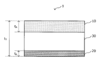
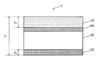
- FIGS. 1A to 1D are explanatory views schematically showing an example of a composite member according to the present embodiment.
- FIGS. 1A to 1D each figure is appropriately enlarged or reduced for the sake of facilitation of explanation, and the figure does not show the actual size and ratio of each part.
- the composite member 1 As shown in FIG. 1A, the composite member 1 according to the present embodiment has an aluminum plate 10, a steel plate 20, and a resin layer 30 interposed between the aluminum plate 10 and the steel plate 20. Therefore, the composite member 1 can be said to be an aluminum-resin-steel (or iron) laminated plate (or composite plate).
- the aluminum plate 10 is not particularly limited except for the conditions related to the thickness described below, and various aluminum plates can be used.
- the aluminum plate may be made of pure Al or may be made of various aluminum alloys.
- the shape of the aluminum plate 10 is not particularly limited, and can be appropriately set according to the object in which the composite member 1 is used.
- the steel plate 20 is not particularly limited except for the conditions related to the thickness described below, and various steel plates can be used depending on the mechanical strength and the like required for the steel plate 20.
- Examples of such a steel plate 20 include ultra-low carbon steel containing Al killed steel, Ti, Nb and the like, and high-strength steel in which the ultra-low carbon steel further contains a reinforcing element such as P, Si and Mn.
- Various steel plates such as these can be mentioned.
- various alloy steel plates such as stainless steel plates can be used.
- the shape of the steel plate 20 is not particularly limited, and can be appropriately set according to the object in which the composite member 1 is used.
- the resin layer 30 is a layer located between the aluminum plate 10 and the steel plate 20.
- the aluminum plate 10 and the steel plate 20 have greatly different linear expansion coefficients, and due to the difference in the linear expansion coefficients, the shape changes due to heat during the manufacture and use of the composite member 1. Can occur.
- the aluminum plate 10 and the steel plate 20 have a specific thickness, and the resin layer 30 exists between the aluminum plate 10 and the steel plate 20 in an appropriate thickness. It is possible to alleviate the difference in the coefficient of linear expansion between the plate 10 and the steel plate 20 and suppress the occurrence of shape change.
- the composite member 1 according to the present embodiment is located at least between the resin layer 30 and the aluminum plate 10 or between the resin layer 30 and the steel plate 20.
- the adhesive layer 40 may be further provided. By further providing the adhesive layer 40, the adhesiveness between the resin layer 30 and the aluminum plate 10 and between the resin layer 30 and the steel plate 20 can be further improved.
- the adhesive layer 40 will be described again below.
- each layer constituting the composite member 1 the thickness of each layer constituting the composite member 1 will be described in detail.
- the thickness of the aluminum plate 10 is represented by t A
- the thickness of the steel plate 20 is represented by t B
- the total thickness of the composite member 1 is represented by t T.
- t A the thickness of the aluminum plate 10
- t B the thickness of the steel plate 20
- t T the total thickness of the composite member 1
- the thickness t A of the aluminum plate 10 is 0.20 to 1.60 mm
- the thickness t B of the steel plate 20 is 0.15 to 1.20 mm
- the total thickness t T of the aluminum plate 10 is 1.50 to 5.00 mm
- the thickness t A of the aluminum plate 10 is equal to or larger than the thickness t B of the steel plate 20.
- the thickness tA of the aluminum plate 10 is 0.20 to 1.60 mm.
- the thickness tA of the aluminum plate 10 is less than 0.20 mm, the heat conduction required for the composite member 1 as a whole is insufficient, and the heat equalization property of the composite member 1 as a whole cannot be realized.
- the thickness t A of the aluminum plate 10 is preferably 0.30 mm or more, more preferably 0.40 mm or more, and further preferably 0.50 mm or more.
- the thickness tA of the aluminum plate 10 according to the present embodiment is more than 1.60 mm, a large amount of aluminum, which is an expensive metal, is used, and low cost cannot be realized.
- the thickness t A of the aluminum plate 10 is preferably 1.20 mm or less, more preferably 1.00 mm or less.
- the thickness t B of the steel plate 20 is 0.15 to 1.20 mm.
- the thickness t B of the steel sheet 20 is preferably 0.20 mm or more, more preferably 0.30 mm or more, and further preferably 0.40 mm or more.
- the thickness t B of the steel plate 20 exceeds 1.20 mm, the thickness of the aluminum plate must be increased as described later. As a result, the strength of the composite member is increased and the press workability is lowered.
- the thickness t B of the steel sheet 20 is preferably 1.00 mm or less, more preferably 0.80 mm or less, and further preferably 0.60 mm or less.
- the thickness t A of the aluminum plate 10 and the thickness t B of the steel plate 20 are within the above ranges, and the thickness t A of the aluminum plate 10 is the steel plate 20. Thickness t B or more.
- the thickness tA of the aluminum plate 10 is increased, the warp caused by the difference in linear expansion coefficient between the aluminum plate 10 and the steel plate 20 becomes large.
- the rigidity of the composite member 1 is increased. As a result, the warp caused by the difference in the coefficient of linear expansion becomes small.
- the thickness t A of the aluminum plate 10 is less than the thickness t B of the steel plate 20, the influence of the steel plate 20 having a large coefficient of linear expansion acts strongly, and even if the resin layer 30 is provided, it is used during manufacturing. It is not possible to suppress the shape change that sometimes occurs due to heat.
- the thickness t A of the aluminum plate 10 is equal to or greater than the thickness t B of the steel plate 20, the difference in the coefficient of linear expansion between aluminum and iron can be alleviated by the resin layer 30, which is caused by heat during manufacturing and use. It is possible to reliably suppress the shape change that occurs and further improve the flatness of the composite member. It is more preferable that the thickness t A of the aluminum plate 10 is thicker than the thickness t B of the steel plate 20 (that is, t A > t B ).
- the total thickness t T of the composite member 1 is 1.50 to 5.00 mm.
- the total thickness t T of the composite material 1 is preferably 2.00 mm or more, more preferably 2.50 mm or more, and further preferably 3.00 mm or more.
- the total thickness t T of the composite member 1 exceeds 5.00 mm, the workability required for the composite member 1 cannot be obtained.
- the composite member 1 is used by joining to other parts by a mechanical fixing means such as a screw. At that time, it is often used by shallow drawing so that the head of a screw or the like does not come out from the surface of the composite member 1.
- the total thickness t T exceeds 5.00 mm, the above-mentioned shallow drawing process becomes difficult.
- the total thickness t T of the composite material 1 is preferably 4.50 mm or less, more preferably 4.00 mm or less.
- the thickness of the resin layer 30 and the thickness of the adhesive layer 40 are obtained by subtracting the thickness t A of the aluminum plate 10 and the thickness t B of the steel plate 20 from the total thickness t T of the composite member 1 according to the present embodiment. Is the total of.
- the ratio t A / t B of the thickness t A of the aluminum plate 10 to the thickness t B of the steel plate 20 is preferably 1.10 to 3.30.
- the lower limit of the ratio t A / t B is more preferably 1.20, still more preferably 1.30, and even more preferably 1.40.
- the upper limit of the ratio t A / t B is more preferably 3.00, further preferably 2.50, even more preferably 2.00, and particularly preferably 1.70.
- the thickness t A of the aluminum plate 10, the thickness t B of the steel plate 20, and the total thickness t T of the composite member 1 are (t A + t B ) / t T ⁇ 0. It is preferable to satisfy the relationship of 65. By satisfying the relationship of (t A + t B ) / t T ⁇ 0.65, the flatness as a composite member is further improved while achieving both heat equalization and suppression of shape change more reliably. It becomes possible.
- the value of (t A + t B ) / t T is more preferably 0.60 or less, still more preferably 0.50 or less, even more preferably 0.40 or less, and particularly preferably 0.35. It is as follows. It is not necessary to set a lower limit of the value of (t A + t B ) / t T , but it may be 0.10, 0.15, 0.20 or 0.28.
- the thickness of each layer constituting the composite member 1 (for example, the thickness t A of the aluminum plate 10, the thickness t B of the steel plate 20, the overall thickness t T , the thickness of the resin layer 30, etc.) can be determined by various known methods. It is possible to measure with.
- the composite member 1 is embedded in a thermosetting resin such as an epoxy resin, and a cutting machine such as a precision cutter is used to parallel the thickness direction at a portion to be observed.
- the sample is cut so as to obtain a cross section, and the obtained cross section is observed with an optical microscope.
- the average thickness of the aluminum plate 10 thus obtained can be defined as the thickness t A of the aluminum plate 10.
- the thickness of the other layer of the composite member 1 according to the present embodiment can also be measured in the same manner as described above.
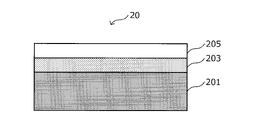
- 2A and 2B are explanatory views schematically showing an example of the configuration of the steel plate 20 according to the present embodiment.
- various steel sheets and alloy steel sheets can be used as the steel sheet 20 according to the present embodiment, but as the steel sheet 20, various plating treatments are applied to the various steel sheets as described above. It is also possible to use a surface-treated steel sheet that has been subjected to various surface treatments.
- the surface treatment includes, for example, various plating treatments such as zinc plating (hot galvanized steel plate, electrozinc plating, etc.) and aluminum plating, chemical conversion treatments such as chromate treatment and non-chromate treatment, and physics such as sandblasting. Examples include, but are not limited to, chemical surface roughening treatments such as target or chemical etching (which can also be regarded as a design processing treatment that adds design properties). Further, the plating may be alloyed or a plurality of types of surface treatments may be applied. As the surface treatment, it is preferable that at least a treatment for the purpose of imparting rust prevention is performed.
- various plating treatments such as zinc plating (hot galvanized steel plate, electrozinc plating, etc.) and aluminum plating
- chemical conversion treatments such as chromate treatment and non-chromate treatment
- physics such as sandblasting. Examples include, but are not limited to, chemical surface roughening treatments such as target or chemical etching (which can also be regarded as a design
- the steel plate 20 has a plating layer 203 located on one surface or both surfaces of the base steel plate 201 and a plating layer, as schematically shown in FIGS. 2A and 2B. It may have a coating film layer 205 located on the surface of 203.
- the plating layer 203 is representative of hot-dip zinc plating, zinc alloy plating, alloyed hot-dip zinc plating, electric zinc plating, electric Zn-Ni plating, hot-dip Zn-5% Al alloy plating and hot-dip 55% Al-Zn alloy plating.
- Hot-dip Zn-Al represented by hot-dip Zn-Al alloy plating, hot-dip Zn-1 to 12% Al-1 to 4% Mg alloy plating, and hot-dip 55% Al-Zn-0.1 to 3% Mg alloy plating.
- various types of plating such as Mg alloy plating, Ni plating, alloyed Ni plating, Al plating, tin plating, and chrome plating can be mentioned.
- zinc-based plating containing Zn is particularly preferable as the plating layer 203 because it has excellent corrosion resistance.
- the coating film layer 205 is a layer composed of, for example, various base paints, various additives, and the like. Although the coating film layer 205 is shown as a single-layer structure in FIGS. 2A and 2B, the coating film layer 205 may have a multi-layer structure composed of a plurality of layers.
- the base paint that can be contained in the coating film layer 205 is not particularly limited, and paints containing various known resins can be used.
- resins include polyacrylic resins, polyolefin resins, polyurethane resins, epoxy resins, polyester resins, polybutyral resins, melamine resins, silicon resins, fluororesins, acrylic resins and the like. These resins can be used as they are or in combination. Further, these resins can be cured with any curing agent.
- Such paints can be used in any form such as organic solvent-based, water-based, and powder-based.
- various additives that can be contained in the coating film layer 205 according to the present embodiment, for example, various extender pigments, colorants, chemical treatment agents, rust preventives, surface-modified metal powders and glass powders, and dispersions are used. Examples thereof include various additives such as agents, leveling agents, antioxidants, defoaming agents, viscosity modifiers, ultraviolet absorbers, waxes, aggregates, additives such as fluororesin beads, and diluting solvents. Since the fluororesin beads are spherical substances made of fluororesin and have lubricity by using fluororesin as a material, it is possible to improve the scratch resistance of the coating film. ..
- the coating film layer 205 contains various extender pigments and colorants as additives, the design of the steel sheet 20 can be improved and the steel sheet 20 can function as a designable steel sheet.
- the composite member 1 according to the present embodiment when used as an exterior material, it can be used as a material showing excellent designability without applying a separate coating.
- the components that can be contained in the coating film layer 205 according to the present embodiment have been described above by citing the coating composition. Usually, when these coating compositions are applied on the plating layer 203, these components and the component composition of the formed film are usually different. In the coating film layer 205, the composition of the coating film composition and the coating film layer 205 after coating are different due to the reaction with the plating layer 203, the volatilization of volatile components in the coating composition, and the like, and the coating film layer 205 is formed. It is usually technically difficult to specify the composition of the coating film layer 205. Further, it is technically difficult to specify the composition of such a coating film layer 205 by instrumental analysis or the like. Therefore, in the present embodiment, the coating film layer 205 to be formed is specified by specifying the components that can be contained in the coating composition.
- the surface of the plating layer 203 has a pattern
- the coating film layer 205 has a transparency in which the pattern can be visually recognized through the coating film layer 205.
- the pattern on the surface of the plating layer 203 include gloss processing represented by buffing and mirror surface processing, and satin finish processing represented by hairline processing, vibration processing, blast processing, dull processing, and the like. be able to.
- the steel plate 20 according to the present embodiment functions as a designable steel sheet by containing various additives as described above or having a pattern formed, so that the composite member 1 according to the present embodiment has an exterior. When used as a material, it can be used as a material showing excellent designability without applying a separate coating.
- the plating layer 203 as described above can be formed by various known plating methods such as a hot-dip plating method and an electroplating method.
- the coating film layer 205 as described above is a generally known coating method (for example, roll coating, curtain flow coating, air spray, airless spray, dipping, bar coating, brush coating, etc.). It can be formed by applying with, drying and solidifying.
- the resin layer 30 is a layer provided to alleviate the difference in linear expansion coefficient between the aluminum plate 10 and the steel plate 20. Since the resin generally has a linear expansion coefficient of about several to several tens ⁇ 10-5 / ° C., by interposing such a resin layer 30 between the aluminum plate 10 and the steel plate 20. It is possible to make the resin follow the shape change that may occur in the aluminum plate 10 and the steel plate 20, and to mitigate the shape change that may occur.
- the resin layer 30 may contain at least one of a polyethylene resin (linear expansion coefficient: 10 to 20 ⁇ 10 -5 / ° C.) or an epoxy resin (linear expansion coefficient: 4 to 6 ⁇ 10 -5 / ° C.). preferable.
- a polyethylene resin linear expansion coefficient: 10 to 20 ⁇ 10 -5 / ° C.
- an epoxy resin linear expansion coefficient: 4 to 6 ⁇ 10 -5 / ° C.
- the composite member 1 according to the present embodiment may be used for a device that generates heat during operation, but the resin layer 30 functions more reliably even in such a heat generation environment.
- the resin contained in is preferably one that does not have a glass transition point Tg in the temperature range to which the device is exposed.
- the temperature of the device fluctuates repeatedly from room temperature to the operating temperature.
- Tg of the resin exists in this temperature range, the glass state and the rubber state are repeated every operation.
- Such a state change is accompanied by a volume change of the resin. Therefore, the volume of the composite member 1 repeatedly expands and contracts, which may impair the durability of the composite material 1.
- the glass transition point Tg of the resin contained in the resin layer 30 is preferably 0 ° C. or lower, or 50 to 180 ° C., more preferably ⁇ 20 ° C. or lower, or 50 to 140 ° C. ..
- the glass transition point Tg of the resin is most preferably 50 to 120 ° C or 80 to 120 ° C.
- the glass transition point of the resin can be measured by various known methods, for example, by measuring the resin of interest using a differential scanning calorimetry (DSC). It is possible to identify.
- DSC differential scanning calorimetry
- the resin contained in the resin layer 30 has a dynamic storage elastic modulus E'and a dynamic loss elastic modulus E "ratio E'/ E” at 100 ° C. of 0.20 to 20. It is preferably 0.0. Since the resin contained in the resin layer 30 has the viscoelastic properties as described above, the resin follows the shape change that may occur in the aluminum plate 10 and the steel plate 20, and the shape change that may occur is more reliably mitigated. It becomes possible.
- the ratio E'/ E "between the dynamic storage elastic modulus E'and the dynamic loss elastic modulus E" at 100 ° C. is more preferably 0.40 to 15.0.
- the ratio E'/ E "between the dynamic storage elastic modulus E'and the dynamic loss elastic modulus E” as described above is the storage elastic modulus obtained by performing the dynamic viscoelastic modulus measurement under the following conditions. It can be confirmed from E'and the loss elastic modulus E'. That is, in such dynamic viscoelasticity measurement, a thermomechanical Analysis device is used, and the storage elastic modulus E'and the loss elastic modulus E'. To identify. At this time, the storage elastic modulus E'and the loss elastic modulus E'are measured in a nitrogen gas stream in a compression mode, 1 Hz, a temperature rise condition of 1 ° C./min, and a range of 25 to 200 ° C.
- the adhesive layer 40 according to the present embodiment is, if necessary, in order to further improve the adhesion between the resin layer 30 and the aluminum plate 10 or at least any one between the resin layer 30 and the steel plate 20. It is a layer provided.
- the adhesive layer 40 is a layer mainly composed of components derived from the adhesive.
- the adhesive used for forming the adhesive layer 40 is not particularly limited, and for example, an epoxy resin-based adhesive, a polyester resin-based adhesive, a urethane resin-based adhesive, or the like, or an adhesive obtained by mixing rubber or elastomer with these adhesives. Agents, adhesives imparted with conductivity, and the like can be used.
- the adhesive layer 40 preferably contains an epoxy resin-based adhesive or a urethane resin-based adhesive (that is, a thermosetting adhesive).
- the resin of the adhesive constituting the adhesive layer 40 has a chemical structure common to that of the resin in the resin layer 30. As a result, the initial adhesion between the adhesive layer 40 and the resin layer 30 can be further improved, and the adhesive strength of the composite member 1 can be further increased.
- the resin of the adhesive constituting the adhesive layer 40 may have a main skeleton common to the resin in the resin layer 30.
- the adhesive resin constituting the adhesive layer 40 may have a side chain functional group common to the resin in the resin layer 30.
- the adhesive layer 40 as described above applies the adhesive as described above to the surface of the aluminum plate 10 or the steel plate 20 by a generally known coating method (for example, roll coating, curtain flow coating, air spray, airless spray). , Immersion, bar coating, brush coating, etc.), bonded to the resin layer 30 or the resin composition to be the resin layer 30, and then dried and solidified to form the resin layer 30.
- a generally known coating method for example, roll coating, curtain flow coating, air spray, airless spray.
- Immersion, bar coating, brush coating, etc. bonded to the resin layer 30 or the resin composition to be the resin layer 30, and then dried and solidified to form the resin layer 30.
- the composite member 1 according to the present embodiment has a specific resin layer 30 between the aluminum plate 10 and the steel plate 20 having a specific thickness, and as a result, excellent flatness can be maintained, resulting in heat soaking property and shape change. It is possible to achieve both the suppression and the suppression of the above.
- the flatness of the composite member 1 according to the present embodiment has a maximum strain of 3.0 mm or less.
- the maximum strain is the maximum value of the value obtained by placing the composite member 1 on the surface plate and subtracting the thickness of the composite member 1 from the strain (wave or warp height) in an arbitrary direction and position. ..
- the maximum strain is preferably 2.0 mm or less, more preferably 1.6 mm or less, still more preferably 1.2 mm or less, and even more preferably 1.0 mm or less.
- the flatness as described above is realized by undergoing a straightening step carried out at a specific timing in the method for manufacturing the composite member 1 according to the present embodiment.
- the composite member 1 according to the present embodiment can be used for a device that generates heat during operation. Since the composite member 1 according to the present embodiment can more reliably suppress the shape change due to the heat generated during manufacturing and use, it can be used for a device that generates heat during operation. You can fully demonstrate its performance.
- parts for home appliances such as display panels typified by organic EL display panels, and various batteries such as Li-ion battery cells, fuel cell cells, and solar cell cells.
- batteries such as Li-ion battery cells, fuel cell cells, and solar cell cells.
- a cell or the like can be mentioned.
- the composite member 1 according to the present embodiment has been described in detail with reference to FIGS. 1A to 2B.
- FIG. 3 is a flow chart showing an example of the flow of the manufacturing method of the composite member 1 according to the present embodiment.
- the method for manufacturing the composite member 1 according to the present embodiment includes an adhesive application step (step S11), a laminate crimping step (step S13), a straightening step (step S15), and a solidification step.
- step S17 the adhesive coating step (step S15) is a step performed as necessary when forming the adhesive layer 40, and is an adhesive coating step in the method for manufacturing the composite member 1 according to the present embodiment.
- Step S11 does not have to exist.
- the adhesive application step (step S11) is a step of applying the above-mentioned adhesive to at least one surface of the aluminum plate 10 or the steel plate 20.
- the adhesive layer 40 is provided at least between the aluminum plate 10 and the resin layer 30 of the composite member 1 to be manufactured, or between the steel plate 20 and the resin layer 30. It becomes possible.
- the adhesive used is as described above, and the coating method used is also as described above.
- the resin composition in a molten state is injected into the gap between the aluminum plate 10 and the steel plate 20 arranged apart from each other, and the aluminum plate 10 and the steel plate 20 are crimped. It is a process to make it.
- the resin composition to be injected is as described above, detailed description thereof will be omitted below.
- the plating layer 203 or the coating film layer 205 is obtained with respect to the base steel plate 201 prior to the laminating pressure bonding step. Is formed.
- a known method may be used. For example, a method of injecting a resin composition in a molten state while holding a gap between the aluminum plate 10 and the steel plate 20 at a predetermined interval may be mentioned. Alternatively, a method may be used in which a molten resin composition is previously applied to the surface of the aluminum plate 10 or the steel plate 20 and then the other metal plate is crimped.
- the resin composition in a molten state is injected into the gap between the aluminum plate 10 and the steel plate 20, and the aluminum plate 10 and the steel plate 20 are pressure-bonded to have the resin composition. Due to the difference in the amount of heat generated and the coefficient of linear expansion between the aluminum plate 10 and the steel plate 20, the composite member 1 undergoes a shape change such as warpage during the cooling process or the like. Therefore, in the straightening step (step S15) according to the present embodiment, when the surface temperature of the composite member 1 is within the range of 180 ° C. or higher than the glass transition point of the resin contained in the resin composition, the composite member 1 Correct the shape of. However, when the glass transition point of the resin contained in the resin composition is 0 ° C. or lower, the shape of the composite member 1 shall be corrected when the temperature is within the range of normal temperature or higher and 180 ° C. or lower.
- the straightening step is performed at the timing when the surface temperature of the composite member 1 exceeds 180 ° C.
- the heat of the resin composition is too high, and the aluminum plate 10 is combined with the aluminum plate 10 in the cooling process after straightening. It is not preferable because the strain caused by the difference in the linear expansion coefficient of the steel sheet 20 further warps and the shape may change again after the straightening step.
- the straightening step is performed at the timing when the surface temperature of the composite member 1 is lower than the glass transition point Tg of the resin, the resin in the glass state cannot sufficiently relieve the internal stress by the straightening, and the composite member is manufactured. The flatness of 1 cannot be maintained.
- the surface temperature of the composite member 1 needs to be equal to or higher than the glass transition point Tg of the resin. Further, in order to reduce the strain caused by the difference in the coefficient of linear expansion between the aluminum plate 10 and the steel plate 20 in the cooling process after straightening, straightening at a lower temperature is preferable. Therefore, in order to improve the flatness of the composite member 1 and prevent the shape change during use of the device, a resin having a glass transition point Tg of 50 to 120 ° C. is used, and the surface temperature of the composite member 1 is 120 ° C. to It is more preferable to correct at a timing within the range of 140 ° C.
- the method for correcting shape changes such as warpage occurring in the aluminum plate 10 and the steel plate 20 is preferably a roller leveler having a degree of processing of 5 or more.
- the maximum value of the curvature given between each straightening roller constituting the roller leveler is set to e (assuming that the material to be straightened is flat), and the elastic limit curvature of the material to be straightened is set to ey.
- the dimensionless amount (e / ey) obtained by dividing the maximum value e of the curvature by the elastic limit curvature ey is defined as the degree of processing by the roller leveler.
- processing conditions that can remove residual stress during cutting plate processing are preferable. That is, it is preferable to perform cutting plate processing immediately after the above-mentioned straightening on the same production line. If straightening is performed after the cutting plate is processed, sufficient straightening strain cannot be given to the tip or tail end at the time of straightening, and there is a concern that the flatness of the tip or tail end may deteriorate, which is not preferable. Further, if the coil is wound after the straightening, the shape is curved due to the winding, so that the coil cannot be wound after the straightening.
- the solidification step (step S17) is a step of solidifying the resin composition located between the aluminum plate 10 and the steel plate 20 to form the resin layer 30.
- solidifying the resin composition means cooling the temperature of the resin composition to less than the glass transition point Tg.
- the glass transition point Tg of the resin of interest is less than 0 ° C.
- the resin composition is cooled to less than the glass transition point Tg of less than 0 ° C.
- the composite member 1 having a laminated structure of an aluminum plate 10 / a resin layer 30 / a steel plate 20 is manufactured.
- the adhesive is applied to the surface of the aluminum plate 10 or the steel plate 20, the adhesive is solidified by the solidification step to form the adhesive layer 40. It is troublesome to cool the composite member 1 to less than 0 ° C., and it is preferable to use a resin composition having a glass transition point Tg of 50 ° C. or higher.
- the cooling rate in the solidification step of the molten resin is preferably small, specifically, for example, 5 ° C./min or less.
- a weight is placed on at least one surface of the aluminum plate 10 or the steel plate 20 (a load is applied), or after the laminating crimping step, a straightening step and a solidification step are carried out while being pressed. Can also be considered. However, as a result of studying these steps by the present inventors, it was not possible to achieve the desired flatness in such steps.
- the device according to the present embodiment is located in a state where at least a part of the composite member 1 as described above is in contact with the surface of the composite member 1 on the side of the aluminum plate 10, and generates heat as it operates. With a device.
- various parts for home appliances such as display panels typified by organic EL display panels, Li-ion battery cells, fuel cell cells, solar cell cells, and the like.
- a battery cell and the like can be mentioned.
- a display device called an organic EL display can be realized.
- various battery devices can be realized by combining various battery cells such as a Li-ion battery cell, a fuel cell, and a solar cell with the composite member 1.
- an organic EL display realized by combining the composite member 1 and the organic EL display panel will be described as an example.
- the organic EL display 500 as an example of the display device includes the composite member 1 according to the present embodiment, the organic EL display panel 3, and further, the organic EL. It may have an electronic board 5 for performing drive control of the display panel 3.
- the organic EL display panel 3 is provided on at least a part of the surface of the composite member 1 on the aluminum plate 10 side, and the electronic substrate 5 is the surface of the composite member 1 on the steel plate 20 side. It is provided in at least a part of.
- the organic EL display panel 3 by providing the organic EL display panel 3 on the aluminum plate 10 side of the composite member 1, it is possible to quickly conduct the heat generated by the organic EL display panel 3 by the aluminum having high thermal conductivity. .. That is, since the composite member 1 itself according to the present embodiment has sufficient heat conduction, it is possible to reliably ensure the heat equalization property in the display surface of the organic EL display panel 3. In addition, since the composite member 1 according to the present embodiment has excellent flatness, the organic EL display panel 3 can be joined to the composite member 1 in a more desirable state, and the organic EL display panel 3 can be joined. It is possible to improve the adhesion between the composite member 1 and the composite member 1, and it is possible to conduct heat evenly.
- the composite member 1 it is possible to prevent the composite member 1 from changing its shape due to the heat generated by the operation of the organic EL display panel 3, so that the organic EL display panel can be prevented from being changed in shape with the operation. Even if heat is generated in 3, the generated heat can be more reliably conducted to the composite member 1 side, and the preferable operating state of the organic EL display panel 3 can be maintained.
- the composite member, the method for manufacturing the composite member, and the device according to the present invention will be specifically described with reference to Examples and Comparative Examples.
- the examples shown below are merely examples of the composite member and the method and device for manufacturing the composite member according to the present invention, and the composite member and the method and device for manufacturing the composite member according to the present invention are limited to the following examples. It's not a thing.
- a commercially available aluminum plate having a desired thickness is prepared as the aluminum plate 10
- the following three types of steel plates (manufactured by Nippon Steel Corporation) having a desired thickness are prepared as the steel plate 20.
- Got ready is prepared.
- ZL-HL Electric Zn-Ni alloy plated steel sheet with hairline processing. A clear coating with a thickness of 6 ⁇ m has been formed on the surface of the steel plate.
- GI-PCM Hot-dip galvanized steel sheet. A coating film layer with a thickness of 20 ⁇ m (primer coating film: 5 ⁇ m + top coating film: 15 ⁇ m) has been formed on the surface of the steel sheet.
- CR-Painting Cold-rolled steel sheet. The surface of the steel sheet was subjected to chemical conversion treatment using zinc phosphate, and further powder coated with a thickness of 50 ⁇ m.
- a resin composition for forming the resin layer 30 As a resin composition for forming the resin layer 30, a commercially available resin shown below was prepared. The glass transition point Tg and the viscoelastic property (dynamic storage elastic modulus E', dynamic loss elastic modulus E ") of the resin used were measured by the method described above.
- PE Polyethylene resin (Novatec HD HF560 manufactured by Japan Polyethylene Corporation)
- EP Epoxy resin (1009 manufactured by Mitsubishi Chemical Corporation)
- PES Polyester resin (SI-173 manufactured by Toyobo Co., Ltd.)
- UR Urethane resin (PANDEX T-5765D manufactured by DIC Covestro Polymer Co., Ltd.)
- the adhesive layer 40 when forming the adhesive layer 40, a commercially available adhesive containing an epoxy resin as a main component (TB1655 manufactured by ThreeBond Co., Ltd.) was used.
- the shape of the composite member 1 was corrected by using a roller leveler at the timing when the surface temperature of the composite member 1 reached a desired temperature. At this time, the degree of processing by the roller leveler was all 5. After such correction, the resin composition was solidified by cooling to a temperature lower than the glass transition point Tg so that the cooling rate was 5 ° C./min to produce a composite member.
- the shape of the composite member 1 is rectangular, and the width-height ratio (width: height is 16: 9.
- the diagonal length of the composite member 1 is 60 inches (1524 mm).
- the obtained composite members were evaluated from the viewpoints of maximum strain, soaking property, steepness, shape change during use, press workability, and color unevenness, and are summarized in Table 1 below.
- the details of the evaluation contents are as follows.
- the obtained composite member was cut into dimensions having a width of 380 mm and a height of 285 mm.
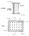
- the steel plate 20 side of the composite member was placed vertically on the hot-dip galvanized steel plate having a thickness of 0.8 mm adjusted to the same dimensions (see the upper figure of FIG. 5), and the four sides of the composite member were installed.
- the composite member and the hot-dip galvanized steel sheet were fixed by using a screw as a means for fixing the composite member and the hot-dip galvanized steel sheet.
- a halogen heater was arranged on the aluminum plate 10 side of the composite member so as to be non-contact, and the aluminum plate 10 was heated.
- the aluminum plate 10 side of the obtained composite member 1 was joined to an organic EL display panel manufactured by Sony Corporation. After setting half of the display screen of the organic EL display to red and the other half to black, the organic EL display was displayed continuously for one hour. After that, the logo of Nippon Steel Corporation (the logo of Nippon Steel Corporation is a logo based on blue) was displayed in the center of the display screen, and the appearance of blue was visually judged by 10 people. .. Based on the number of people who felt the difference in color, the evaluation was made according to the following criteria. Scores S to B were passed. In addition, No. in Table 1 below. In 10 and 23, the evaluation result of "-" means that the evaluation could not be performed because the shape when processed was bad and could not be incorporated into the organic EL display panel. S: 0 people A: 1, 2, 3 people B: 4, 5, 6 people C: 7 people or more
- the composite member corresponding to the embodiment of the present invention has excellent heat soaking property and press workability, and while the shape change during manufacturing and use is suppressed, the present invention is used. It can be seen that the composite member corresponding to the comparative example fails in any of the heat soaking property, the press workability, and the shape change during manufacturing or use.
- Organic EL display panel 1 Composite member 3 Organic EL display panel 5 Electronic substrate 10 Aluminum plate 20 Steel plate 30 Resin layer 40 Adhesive layer 201 Base steel plate 203 Plating layer 205 Coating layer 500 Organic EL display
Landscapes
- Engineering & Computer Science (AREA)
- Mechanical Engineering (AREA)
- Laminated Bodies (AREA)
- Electroluminescent Light Sources (AREA)
- Cooling Or The Like Of Electrical Apparatus (AREA)
Abstract
Description
かかる知見に基づき完成された本発明の要旨は、以下の通りである。
(2)前記複合部材の平坦度は、任意の方向での最大ひずみが3.0mm以下である、(1)又は(2)に記載の複合部材。
(3)前記複合部材の平坦度は、任意の方向での最大ひずみが2.0mm以下である、(1)又は(2)に記載の複合部材。
(4)前記鋼板の厚みtBに対する前記アルミニウム板の厚みtAの比率tA/tBは、1.10~3.30である、(1)~(3)の何れか1つに記載の複合部材。
(5)前記アルミニウム板の厚みtA、前記鋼板の厚みtB、及び、前記複合部材の全体の厚みtTは、(tA+tB)/tT≦0.65の関係を満足する、(1)~(4)の何れか1つに記載の複合部材。
(6)前記樹脂層は、ポリエチレン樹脂又はエポキシ樹脂を含む、(1)~(5)の何れか1つに記載の複合部材。
(7)前記樹脂層に含有される樹脂のガラス転移点Tgは、0℃以下、又は、50~180℃である、(1)~(6)の何れか1つに記載の複合部材。
(8)前記樹脂層に含有される樹脂の100℃における動的貯蔵弾性率E’と動的損失弾性率E”との比率E’/E”は、0.20~20.0である、(1)~(7)の何れか1つに記載の複合部材。
(9)前記樹脂層と前記アルミニウム板との間、又は、前記樹脂層と前記鋼板との間の少なくとも何れかに、接着剤層を更に備える、(1)~(8)の何れか1つに記載の複合部材。
(10)前記鋼板は、少なくとも片方の面上に位置するめっき層と、前記めっき層上に位置する塗膜層と、を有している、(1)~(9)の何れか1つに記載の複合部材。
(11)(1)~(10)の何れか1つに記載の複合部材と、前記複合部材における前記アルミニウム板側の表面に、少なくとも一部が接触した状態で位置する、稼働に伴い発熱するデバイスと、を有する、機器。
(12)前記稼働に伴い発熱するデバイスは、有機ELディスプレイパネルであり、前記機器は、有機ELディスプレイである、(11)に記載の機器。
<複合部材の全体構成について>
まず、図1A~図1Dを参照しながら、本発明の実施形態に係る複合部材の全体的な構成について説明する。図1A~図1Dは、本実施形態に係る複合部材の一例を模式的に示した説明図である。なお、図1A~図1Dでは、説明の容易化のために、各図適宜拡大、縮小しており、図は各部の実際の大きさ及び比率を示すものではない。
続いて、複合部材1を構成する各層の厚みについて、詳細に説明する。以下の説明では、図1A~図1Dに示したように、アルミニウム板10の厚みをtAと表し、鋼板20の厚みをtBと表し、複合部材1の全体の厚みをtTと表すこととする。
以下、上記の条件について、より詳細に説明する。
本実施形態に係る複合部材1において、アルミニウム板10の厚みtAは、0.20~1.60mmとする。アルミニウム板10の厚みtAが0.20mm未満である場合には、複合部材1全体として求められる熱伝導が不足することで、複合部材1全体としての均熱性を実現することができない。アルミニウム板10の厚みtAを0.20mm以上とすることで、複合部材1に求められる均熱性を実現することが可能となる。アルミニウム板10の厚みtAは、好ましくは0.30mm以上であり、より好ましくは0.40mm以上であり、更に好ましくは0.50mm以上である。一方、本実施形態に係るアルミニウム板10の厚みtAが1.60mm超である場合には、高価な金属であるアルミニウムを多く使用することとなり、低コスト性を実現することができない。アルミニウム板10の厚みtAを1.60mm以下とすることで、低コスト性を保持しながら、所望の均熱性を実現することが可能となる。アルミニウム板10の厚みtAは、好ましくは1.20mm以下であり、より好ましくは1.00mm以下である。
本実施形態に係る複合部材1において、鋼板20の厚みtBは、0.15~1.20mmとする。鋼板20の厚みtBが0.15mm未満である場合には、複合部材1全体として求められる剛性を実現することができない。鋼板20の厚みtBを0.15mm以上とすることで、複合部材1全体として求められる剛性を実現することが可能となる。鋼板20の厚みtBは、好ましくは0.20mm以上であり、より好ましくは0.30mm以上であり、更に好ましくは0.40mm以上である。一方、鋼板20の厚みtBが1.20mm超となる場合には、後述のとおりアルミニウムの板厚も大きくしなければならない。その結果、複合部材としての強度が大きくなり、プレス加工性が低下する。鋼板20の厚みtBを1.20mm以下とすることで、均熱性、剛性及びプレス加工性の並立が可能となる。鋼板20の厚みtBは、好ましくは1.00mm以下であり、より好ましくは0.80mm以下であり、更に好ましくは0.60mm以下である。なお、鋼板20として、以下で説明するような、母材鋼板の表面にめっき層や塗膜層を有する各種の鋼板を使用する場合、これらめっき層や塗膜層を含めた全体の厚みを、鋼板20の厚みtBとする。
本実施形態に係る複合部材1において、アルミニウム板10の厚みtA、及び、鋼板20の厚みtBが上記の範囲内となったうえで、更に、アルミニウム板10の厚みtAは、鋼板20の厚みtB以上とする。アルミニウム板10の厚みtAを大きくすると、アルミニウム板10と鋼板20の線膨張係数差に起因する反りは大きくなる。一方、アルミニウム板10の厚みtAを大きくすることで複合部材1としての剛性が増大する。その結果、線膨張係数差に起因する反りは小さくなる。アルミニウム板10の厚みtAが鋼板20の厚みtB未満である場合には、線膨張係数の大きな鋼板20の影響が強く作用してしまい、樹脂層30を設けたとしても、製造時及び使用時に熱に起因して発生する形状変化を抑制することができない。アルミニウム板10の厚みtAが鋼板20の厚みtB以上となることで、アルミニウムと鉄との線膨張係数の違いを樹脂層30によって緩和することが可能となり、製造時及び使用時に熱に起因して発生する形状変化を確実に抑制して、複合部材としての平坦度をより向上させることが可能となる。アルミニウム板10の厚みtAは、鋼板20の厚みtBよりも厚い(すなわち、tA>tBである)ことが、より好ましい。
本実施形態に係る複合部材1において、複合部材1の全体の厚みtTは、1.50~5.00mmとする。複合部材1の全体の厚みtTが1.50mm未満となる場合には、均熱性と形状変化の抑制との両立を図りながら、複合部材としての平坦度をより向上させることができない。複合部材1の全体の厚みtTを1.50mm以上とすることで、均熱性と形状変化の抑制との両立を図りながら、複合部材としての平坦度をより向上させることが可能となる。複合材1の全体の厚みtTは、好ましくは2.00mm以上であり、より好ましくは2.50mm以上であり、更に好ましくは3.00mm以上である。一方、複合部材1の全体の厚みtTが5.00mm超となる場合には、複合部材1に求められる加工性が得られない。複合部材1は、他の部品とビス等の機械的な固定手段で接合することで使用される。その際、複合部材1の面よりもビス等の頭が出ないように浅絞り加工して使用することが多い。全体の厚みtTが5.00mm超の場合、上記の浅絞り加工が困難となる。複合部材1の全体の厚みtTを5.00mm以下とすることで、熱性と加工性との両立を図ることが可能となる。複合材1の全体の厚みtTは、好ましくは4.50mm以下であり、より好ましくは4.00mm以下である。
本実施形態に係る複合部材1において、鋼板20の厚みtBに対するアルミニウム板10の厚みtAの比率tA/tBは、1.10~3.30であることが好ましい。比率tA/tBが1.10~3.30となることで、より一層確実に、均熱性と形状変化の抑制との両立を図りながら、複合部材としての平坦度をより向上させることが可能となる。比率tA/tBの下限は、より好ましくは1.20であり、更に好ましくは1.30であり、より一層好ましくは1.40である。また、比率tA/tBの上限は、より好ましくは3.00であり、更に好ましくは2.50であり、より一層好ましくは2.00であり、特に好ましくは1.70である。
本実施形態に係る複合部材1において、アルミニウム板10の厚みtA、鋼板20の厚みtB、及び、複合部材1の全体の厚みtTは、(tA+tB)/tT≦0.65の関係を満足することが好ましい。(tA+tB)/tT≦0.65の関係が満たされることで、より一層確実に、均熱性と形状変化の抑制との両立を図りながら、複合部材としての平坦度をより向上させることが可能となる。(tA+tB)/tTの値は、より好ましくは0.60以下であり、更に好ましくは0.50以下であり、より一層好ましくは0.40以下であり、特に好ましくは0.35以下である。(tA+tB)/tTの値の下限を特に定める必要はないが、0.10、0.15、0.20又は0.28としてもよい。
ここで、複合部材1を構成する各層の厚み(例えば、アルミニウム板10の厚みtA、鋼板20の厚みtB、全体の厚みtT、樹脂層30の厚み等)は、公知の各種の方法で測定することが可能である。
図2A及び図2Bは、本実施形態に係る鋼板20の構成の一例を模式的に示した説明図である。
上記のように、本実施形態に係る鋼板20として、各種の鋼板や合金鋼板を用いることが可能であるが、鋼板20として、上記のような各種の鋼板に対して各種のめっき処理をはじめとする各種の表面処理を施した表面処理鋼板を用いることも可能である。
本実施形態に係る樹脂層30は、アルミニウム板10と鋼板20との間の線膨張係数の違いを緩和するために設けられる層である。樹脂は、一般的に、数~数十×10-5/℃程度の線膨張係数を有しているため、このような樹脂層30をアルミニウム板10と鋼板20との間に介在させることで、アルミニウム板10や鋼板20に生じうる形状変化に樹脂を追随させて、生じうる形状変化を緩和させることが可能となる。
本実施形態に係る接着剤層40は、樹脂層30とアルミニウム板10との間、又は、樹脂層30と鋼板20との間の少なくとも何れかの密着性をより向上させるために、必要に応じて設けられる層である。
本実施形態に係る複合部材1は、特定の厚みを有するアルミニウム板10及び鋼板20の間に、特定の樹脂層30が存在することで、優れた平坦度を保持できる結果、均熱性と形状変化の抑制との両立を図ることが可能となる。本実施形態に係る複合部材1の平坦度は、最大ひずみが3.0mm以下である。ここで、最大ひずみとは、複合部材1を定盤上に置き、任意の方向及び位置でのひずみ(波又は反りの高さ)から複合部材1の厚さを減じた値の最大値である。ただし、波のピッチが1mを超える複合部材1については、任意の位置の長さ1mに対して適用する。最大ひずみは、好ましくは2.0mm以下であり、より好ましくは1.6mm以下であり、更に好ましくは1.2mm以下であり、より一層好ましくは1.0mm以下である。
以上説明したような、本実施形態に係る複合部材1は、稼働に伴い発熱するデバイスに用いることが可能である。本実施形態に係る複合部材1は、製造時及び使用時に発生する熱に起因する形状変化をより確実に抑制することが可能であるため、稼働に伴い発熱するデバイスに対して用いられることで、その性能を遺憾なく発揮できる。
続いて、図3を参照しながら、本実施形態に係る複合部材1の製造方法について説明する。図3は、本実施形態に係る複合部材1の製造方法の流れの一例を示した流れ図である。
接着剤塗布工程(ステップS11)は、アルミニウム板10又は鋼板20の少なくとも何れかの表面に、上記のような接着剤を塗布する工程である。かかる塗布工程を設けることで、製造される複合部材1のアルミニウム板10と樹脂層30との間、又は、鋼板20と樹脂層30との間、の少なくとも何れかに、接着剤層40を設けることが可能となる。
ラミネート圧着工程(ステップS13)は、互いに離隔させて配置されたアルミニウム板10と鋼板20との間の空隙に、溶融状態にある樹脂組成物を注入して、アルミニウム板10と鋼板20とを圧着させる工程である。ここで、注入される樹脂組成物については、上記の通りであるため、以下では詳細な説明は省略する。また、鋼板20として、めっき層203や塗膜層205が形成されている鋼板を用いる場合には、かかるラミネート圧着工程に先立って、母材鋼板201に対して、めっき層203や塗膜層205を形成しておく。ラミネート圧着の方法としては、公知の方法でよい。例えば、アルミニウム板10と鋼板20との間の空隙を予め決めた間隔に保持した状態において、溶融状態にある樹脂組成物を注入する方法などが挙げられる。また、アルミニウム板10又は鋼板20の表面に溶融状態にある樹脂組成物を予め塗布しておいた上で、他方の金属板を圧着するような方法としてもよい。
上記のように、アルミニウム板10と鋼板20との間の空隙に、溶融状態にある樹脂組成物が注入され、アルミニウム板10と鋼板20とが圧着されることで、かかる樹脂組成物が有している熱量及びアルミニウム板10と鋼板20の線膨張係数の差に起因して、冷却過程等で複合部材1に反り等の形状変化が生じる。そこで、本実施形態に係る矯正工程(ステップS15)では、複合部材1の表面温度が、樹脂組成物に含有される樹脂のガラス転移点以上180℃以下の範囲内であるときに、複合部材1の形状を矯正する。ただし、樹脂組成物に含有される樹脂のガラス転移点が0℃以下である場合には、常温以上180℃以下の範囲内であるときに、複合部材1の形状を矯正するものとする。
固化工程(ステップS17)は、アルミニウム板10と鋼板20との間に位置する上記樹脂組成物を固化させて、樹脂層30とする工程である。ここで、樹脂組成物を固化させるとは、樹脂組成物の温度をそのガラス転移点Tg未満に冷却することをいう。ここで、着目する樹脂のガラス転移点Tgが0℃未満である場合には、0℃未満であるガラス転移点Tg未満まで、樹脂組成物を冷却することとする。これにより、アルミニウム板10/樹脂層30/鋼板20という積層構造を有する複合部材1が製造される。また、アルミニウム板10や鋼板20の表面に接着剤が塗布されている場合には、かかる固化工程を経ることで接着剤が固化して、接着剤層40が形成される。なお、複合部材1を0℃未満に冷却することは面倒であり、ガラス転移点Tgを50℃以上である樹脂組成物とすることが好ましい。
以上説明したような本実施形態に係る複合部材1と、稼働に伴い発熱するデバイスと、を用いることで、以下のような機器を実現することが可能となる。
すなわち、本実施形態に係る機器は、以上説明したような複合部材1と、かかる複合部材1におけるアルミニウム板10の側の表面に、少なくとも一部が接触した状態で位置する、稼働に伴い発熱するデバイスと、を有する。
GI-PCM:溶融亜鉛めっき鋼板。鋼板表面に、厚み20μmの塗膜層(プライマー塗膜:5μm+トップ塗膜:15μm)を形成済み。
CR-塗装:冷延鋼板。鋼板表面に、リン酸亜鉛を用いた化成処理を施し、更に、厚み50μmの粉体塗装を施した。
EP:エポキシ樹脂(三菱ケミカル株式会社製1009)
PES:ポリエステル樹脂(東洋紡株式会社製SI-173)
UR:ウレタン樹脂(DIC Covestro Polymer株式会社製PANDEX T-5765D)
得られた複合部材について、任意の方向での最大ひずみを測定した。
得られた複合部材から、70mm×180mmのサンプルを作製した。アルミニウム板10側の一方の端部にラバーヒーターを取り付け、ヒーターの出力を3.4Wで一定として30分保持し、端部から50mmごとに、鋼板20側から測温した。ヒーターの温度と、端部から150mm離れた位置の温度との温度差ΔTを算出した。得られた温度差ΔTに基づき、以下のような基準で評価を行った。評点S~Bを合格とした。
S:ΔT 15℃以下
A:ΔT 15℃超25℃以下
B:ΔT 25℃超35℃以下
C:ΔT 35℃超
得られた複合部材について、上記と同様にして定盤上で最大ひずみを測定するとともに、ひずみの現れる間隔であるピッチを測定した。得られた最大ひずみ及びピッチから、急峻度(%)=(最大ひずみ÷ピッチ)×100を算出し、得られた急峻度に基づき、以下のような基準で評価を行った。評点S~Bを合格とした。
S:急峻度 0.5%以下
A:急峻度 0.5%超1.0%以下
B:急峻度 1.0%超2.0%以下
C:急峻度 2.0%超
得られた複合部材が、有機ELディスプレイパネルと接合される場合を模して、図5に示したような試験体を作製し、以下のようにして評価を行った。
S:最大変位 0.5mm以下
A:最大変位 0.5mm超1.0mm以下
B:最大変位 1.0mm超1.8mm以下
C:最大変位 1.8mm超
得られた複合部材について、アルミニウム板10側が凹となるように、エリクセン試験機(JIS Z 2247に準拠)にて試験片が破断するまで押し出し加工を施した。割れが発生する最大の押し出し高さD(単位:mm)を求めた。得られた高さDに基づき、以下のような基準で評価を行った。評点S~Bを合格とした。
S:高さD 7mm以上
A:高さD 5mm以上7mm未満
B:高さD 3mm以上5mm未満
C:高さD 3mm未満
得られた複合部材1のアルミニウム板10側を、ソニー株式会社製の有機ELディスプレイパネルに接合させた。有機ELディスプレイの表示画面の半分を赤色、残り半分を黒色に設定したうえで、有機ELディスプレイを1時間連続で表示させた。その後、表示画面の中央に、日本製鉄株式会社のロゴ(日本製鉄株式会社のロゴは、青色を基調としたロゴである。)を表示させて、青色の見え方を、10人で目視判定した。色の差を感じた人の人数に基づき、以下のような基準で評価を行った。評点S~Bを合格とした。なお、以下の表1のNo.10、23において、評価結果が「-」となっているのは、加工した際の形状が悪く、有機ELディスプレイパネルに組み込むことができなかったために、評価できなかったことを意味している。
S:0人
A:1、2、3人のいずれか
B:4、5、6人のいずれか
C:7人以上

3 有機ELディスプレイパネル
5 電子基板
10 アルミニウム板
20 鋼板
30 樹脂層
40 接着剤層
201 母材鋼板
203 めっき層
205 塗膜層
500 有機ELディスプレイ
Claims (12)
- アルミニウム板と、
鋼板と、
前記アルミニウム板及び前記鋼板の間に介在する樹脂層と、
を備える複合部材であって、
前記アルミニウム板の厚みtAは、0.20~1.60mmであり、
前記鋼板の厚みtBは、0.15~1.20mmであり、
前記複合部材の全体の厚みtTは、1.50~5.00mmであり、
前記アルミニウム板の厚みtAは、前記鋼板の厚みtB以上である、複合部材。 - 前記複合部材の平坦度は、任意の方向での最大ひずみが3.0mm以下である、請求項1に記載の複合部材。
- 前記複合部材の平坦度は、任意の方向での最大ひずみが2.0mm以下である、請求項1又は2に記載の複合部材。
- 前記鋼板の厚みtBに対する前記アルミニウム板の厚みtAの比率tA/tBは、1.10~3.30である、請求項1~3の何れか1項に記載の複合部材。
- 前記アルミニウム板の厚みtA、前記鋼板の厚みtB、及び、前記複合部材の全体の厚みtTは、(tA+tB)/tT≦0.65の関係を満足する、請求項1~4の何れか1項に記載の複合部材。
- 前記樹脂層は、ポリエチレン樹脂又はエポキシ樹脂を含む、請求項1~5の何れか1項に記載の複合部材。
- 前記樹脂層に含有される樹脂のガラス転移点Tgは、0℃以下、又は、50~180℃である、請求項1~6の何れか1項に記載の複合部材。
- 前記樹脂層に含有される樹脂の100℃における動的貯蔵弾性率E’と動的損失弾性率E”との比率E’/E”は、0.20~20.0である、請求項1~7の何れか1項に記載の複合部材。
- 前記樹脂層と前記アルミニウム板との間、又は、前記樹脂層と前記鋼板との間の少なくとも何れかに、接着剤層を更に備える、請求項1~8の何れか1項に記載の複合部材。
- 前記鋼板は、少なくとも片方の面上に位置するめっき層と、前記めっき層上に位置する塗膜層と、を有している、請求項1~9の何れか1項に記載の複合部材。
- 請求項1~10の何れか1項に記載の複合部材と、
前記複合部材における前記アルミニウム板側の表面に、少なくとも一部が接触した状態で位置する、稼働に伴い発熱するデバイスと、
を有する、機器。 - 前記稼働に伴い発熱するデバイスは、有機ELディスプレイパネルであり、
前記機器は、有機ELディスプレイである、請求項11に記載の機器。
Priority Applications (3)
| Application Number | Priority Date | Filing Date | Title |
|---|---|---|---|
| CN202180087801.4A CN116802045A (zh) | 2021-01-07 | 2021-12-10 | 复合构件和设备 |
| JP2022516753A JP7148021B1 (ja) | 2021-01-07 | 2021-12-10 | 機器 |
| JP2022111042A JP7360068B2 (ja) | 2021-01-07 | 2022-07-11 | 複合部材 |
Applications Claiming Priority (2)
| Application Number | Priority Date | Filing Date | Title |
|---|---|---|---|
| JP2021001545 | 2021-01-07 | ||
| JP2021-001545 | 2021-01-07 |
Publications (1)
| Publication Number | Publication Date |
|---|---|
| WO2022149409A1 true WO2022149409A1 (ja) | 2022-07-14 |
Family
ID=82357681
Family Applications (1)
| Application Number | Title | Priority Date | Filing Date |
|---|---|---|---|
| PCT/JP2021/045577 Ceased WO2022149409A1 (ja) | 2021-01-07 | 2021-12-10 | 複合部材及び機器 |
Country Status (4)
| Country | Link |
|---|---|
| JP (2) | JP7148021B1 (ja) |
| CN (1) | CN116802045A (ja) |
| TW (1) | TWI793917B (ja) |
| WO (1) | WO2022149409A1 (ja) |
Citations (4)
| Publication number | Priority date | Publication date | Assignee | Title |
|---|---|---|---|---|
| JPS6131247A (ja) * | 1984-07-23 | 1986-02-13 | 株式会社アルポリツク | 異種金属複合板およびその製造方法 |
| JPH06171016A (ja) * | 1992-12-10 | 1994-06-21 | Nippon Metal Ind Co Ltd | 曲げ加工性に優れた樹脂サンドイッチ型制振金属材料 |
| JPH108266A (ja) * | 1996-06-21 | 1998-01-13 | Nippon Steel Corp | 耐結露性に優れた被覆金属板 |
| JP2017201710A (ja) * | 2011-11-18 | 2017-11-09 | ギガ ソーラー エフピーシー | 新規の太陽光モジュール、支持層スタック、およびその製造方法 |
Family Cites Families (10)
| Publication number | Priority date | Publication date | Assignee | Title |
|---|---|---|---|---|
| EP0108710A2 (de) * | 1982-10-08 | 1984-05-16 | Ciba-Geigy Ag | Laminate aus Metallplatten und thermoplastischem Material |
| JP2006085920A (ja) * | 2004-09-14 | 2006-03-30 | Nippon Steel Corp | 有機el背面キャップ |
| US8127445B2 (en) * | 2008-04-03 | 2012-03-06 | E. I. Du Pont De Nemours And Company | Method for integrating heat transfer members, and an LED device |
| JP2011140067A (ja) * | 2009-12-10 | 2011-07-21 | Kobe Steel Ltd | 鋼板とアルミニウム板との接合構造体の製造方法およびこの製造方法により製造された鋼板とアルミニウム板との接合構造体 |
| BR112015010088A2 (pt) * | 2012-11-05 | 2017-07-11 | 3M Innovative Properties Co | adesivo termofixo, componente automotivo que usa adesivo termofixo e método de fabricação do mesmo |
| JP6057330B2 (ja) * | 2013-01-17 | 2017-01-11 | 日本発條株式会社 | 複合材及び複合材の製造方法 |
| JP6621694B2 (ja) * | 2016-03-25 | 2019-12-18 | 株式会社神戸製鋼所 | ポリオレフィン系樹脂接着用表面処理鋼板及びそれを用いた複合部材 |
| JP6751046B2 (ja) * | 2017-03-29 | 2020-09-02 | 株式会社神戸製鋼所 | ポリオレフィン接着用表面処理金属板、複合部材、及び複合部材の製造方法 |
| JP6692012B1 (ja) * | 2018-06-26 | 2020-05-13 | 株式会社キルトプランニングオフィス | 照明装置 |
| JP7082004B2 (ja) * | 2018-07-30 | 2022-06-07 | 日鉄鋼板株式会社 | 塗装金属板 |
-
2021
- 2021-12-10 WO PCT/JP2021/045577 patent/WO2022149409A1/ja not_active Ceased
- 2021-12-10 TW TW110146376A patent/TWI793917B/zh active
- 2021-12-10 CN CN202180087801.4A patent/CN116802045A/zh active Pending
- 2021-12-10 JP JP2022516753A patent/JP7148021B1/ja active Active
-
2022
- 2022-07-11 JP JP2022111042A patent/JP7360068B2/ja active Active
Patent Citations (4)
| Publication number | Priority date | Publication date | Assignee | Title |
|---|---|---|---|---|
| JPS6131247A (ja) * | 1984-07-23 | 1986-02-13 | 株式会社アルポリツク | 異種金属複合板およびその製造方法 |
| JPH06171016A (ja) * | 1992-12-10 | 1994-06-21 | Nippon Metal Ind Co Ltd | 曲げ加工性に優れた樹脂サンドイッチ型制振金属材料 |
| JPH108266A (ja) * | 1996-06-21 | 1998-01-13 | Nippon Steel Corp | 耐結露性に優れた被覆金属板 |
| JP2017201710A (ja) * | 2011-11-18 | 2017-11-09 | ギガ ソーラー エフピーシー | 新規の太陽光モジュール、支持層スタック、およびその製造方法 |
Also Published As
| Publication number | Publication date |
|---|---|
| TW202230460A (zh) | 2022-08-01 |
| JPWO2022149409A1 (ja) | 2022-07-14 |
| CN116802045A (zh) | 2023-09-22 |
| JP7148021B1 (ja) | 2022-10-05 |
| JP2022125350A (ja) | 2022-08-26 |
| JP7360068B2 (ja) | 2023-10-12 |
| TWI793917B (zh) | 2023-02-21 |
Similar Documents
| Publication | Publication Date | Title |
|---|---|---|
| TWI286100B (en) | Precoated metal sheet for light reflectors | |
| CN103748253B (zh) | 表面处理热浸镀钢材 | |
| CN105555526A (zh) | 金属-塑料夹芯板及其制造方法 | |
| KR20110138490A (ko) | 자동차 오이엠용 용접성 프리-프라임용 도료 조성물 및 이를 이용한 코팅방법 | |
| EP3363629B1 (en) | Resin-coated sn-plated steel sheet, and method and facility for manufacturing the same | |
| US20160010843A1 (en) | Pre-coated aluminum sheet, aluminum sheet, and heat sink for onboard led lighting | |
| JP2019181946A (ja) | 金属−炭素繊維強化樹脂材料複合体及び金属―炭素繊維強化樹脂材料複合体の製造方法 | |
| JP7436943B2 (ja) | プレコートめっき鋼板及び成形品 | |
| JP7001214B1 (ja) | プレコート金属板、火傷防止カバー及びプレコート金属板の製造方法 | |
| KR101615456B1 (ko) | 수지층의 밀착성이 향상된 수지 피복 강판 및 그 제조방법 | |
| JP7360068B2 (ja) | 複合部材 | |
| JP6965992B2 (ja) | 金属−炭素繊維強化樹脂材料複合体及び金属−炭素繊維強化樹脂材料複合体の製造方法 | |
| KR101372747B1 (ko) | 가공성이 우수한 수지코팅 강판 및 이에 사용되는 수지조성물 | |
| JP2015227494A (ja) | 高強度鋼部品及びその製造方法 | |
| JP6060643B2 (ja) | 樹脂被覆鋼板製イージーオープン缶蓋及びその製造方法 | |
| JP7082004B2 (ja) | 塗装金属板 | |
| JP5722597B2 (ja) | ポリ塩化ビニル樹脂被覆鋼板の製造方法 | |
| CN102470640B (zh) | 预涂层金属板 | |
| JP2004292943A (ja) | 塗膜密着性と鮮映性に優れ環境負荷の小さい高耐食性塗装鋼板 | |
| JP2004225157A (ja) | 鮮映性の優れた高耐食性塗装鋼板 | |
| JP4983306B2 (ja) | 塗装鋼板、加工品及び薄型テレビ用パネル | |
| US20170333943A1 (en) | Method for producing coated metal strip | |
| TWI615207B (zh) | 抗高溫氧化塗裝鋼板及其製造方法與應用 | |
| KR100328518B1 (ko) | 다층 피복강판 및 그 제조방법 | |
| TW202039932A (zh) | 耐高溫氧化之複合鍍鋅鋼板及其製造方法與應用 |
Legal Events
| Date | Code | Title | Description |
|---|---|---|---|
| ENP | Entry into the national phase |
Ref document number: 2022516753 Country of ref document: JP Kind code of ref document: A |
|
| 121 | Ep: the epo has been informed by wipo that ep was designated in this application |
Ref document number: 21917630 Country of ref document: EP Kind code of ref document: A1 |
|
| WWE | Wipo information: entry into national phase |
Ref document number: 202180087801.4 Country of ref document: CN |
|
| NENP | Non-entry into the national phase |
Ref country code: DE |
|
| 122 | Ep: pct application non-entry in european phase |
Ref document number: 21917630 Country of ref document: EP Kind code of ref document: A1 |