WO2022149335A1 - マスク - Google Patents
マスク Download PDFInfo
- Publication number
- WO2022149335A1 WO2022149335A1 PCT/JP2021/039368 JP2021039368W WO2022149335A1 WO 2022149335 A1 WO2022149335 A1 WO 2022149335A1 JP 2021039368 W JP2021039368 W JP 2021039368W WO 2022149335 A1 WO2022149335 A1 WO 2022149335A1
- Authority
- WO
- WIPO (PCT)
- Prior art keywords
- plan
- mask
- folded state
- view
- wearer
- Prior art date
- Legal status (The legal status is an assumption and is not a legal conclusion. Google has not performed a legal analysis and makes no representation as to the accuracy of the status listed.)
- Ceased
Links
Images

Classifications
-
- A—HUMAN NECESSITIES
- A41—WEARING APPAREL
- A41D—OUTERWEAR; PROTECTIVE GARMENTS; ACCESSORIES
- A41D13/00—Professional, industrial or sporting protective garments, e.g. surgeons' gowns or garments protecting against blows or punches
- A41D13/05—Professional, industrial or sporting protective garments, e.g. surgeons' gowns or garments protecting against blows or punches protecting only a particular body part
- A41D13/11—Protective face masks, e.g. for surgical use, or for use in foul atmospheres
Definitions
- This disclosure relates to masks.
- the first mask according to the present invention is The mask body, which covers at least a part of the wearer's face, It is provided with an ear hook portion extending from the mask main body portion. It can be folded by folding at the folding line located in the center in the width direction. In the plan view in the folded state, with respect to the reference axis connecting the upper end of the bending line that is closer to the wearer's eyes and the lower end of the bending line that is away from the eyes when worn.
- the straight line connecting the most bent bending point of the bending line and the upper end thereof is inclined at an angle of 30 ° or more and 40 ° or less.
- the distance from the reference axis to the bending point may be 15 mm or more and 25 mm or less in the plan view in the folded state.
- the length from the upper end to the bending point along the direction parallel to the reference axis is 25 mm or more and 30 mm or less in the plan view in the folded state. good.
- the second mask according to the present invention is The mask body, which covers at least a part of the wearer's face, It is provided with an ear hook portion extending from the mask main body portion. It can be folded by folding at the folding line located in the center in the width direction. In the plan view in the folded state, with respect to the reference axis connecting the upper end of the bending line that is closer to the wearer's eyes and the lower end of the bending line that is away from the eyes when worn.
- the straight line connecting the maximum protruding position of the bending line farthest from the reference axis and the upper end thereof is inclined at an angle of 30 ° or more and 40 ° or less.
- the distance from the reference axis to the maximum protrusion position may be 15 mm or more and 25 mm or less in the plan view in the folded state.
- the length from the upper end to the maximum protruding position along the direction parallel to the reference axis is 25 mm or more and 30 mm or less. May be good.
- the direction orthogonal to the reference axis line connecting the upper end and the lower end of the bending line is defined as the first direction.
- the length along the first direction may be 160 mm or more and 190 mm or less.
- the direction parallel to the reference axis connecting the upper end and the lower end of the bending line is defined as the second direction.
- the length from the upper end to the lower end along the second direction may be 110 mm or more and 135 mm or less.
- the lower edge portion up to the lower contact point where the tangent line and the ear hook portion contact may be recessed.
- the third mask according to the present invention is The mask body, which covers at least a part of the wearer's face, It is provided with an ear hook portion extending from the mask main body portion. It can be folded by folding at the folding line located in the center in the width direction. In the plan view in the folded state, the lower end to the lower side with respect to the lower tangent line that passes through the lower end of the bending line that is the side away from the wearer's eyes when worn and is in contact with the ear hook portion. The lower edge to the lower contact where the tangent and the ear hook contact is recessed.
- the maximum separation distance of the lower edge portion with respect to the lower tangent line may be 2 mm or more and 10 mm or less in the plan view in the folded state.
- the direction orthogonal to the reference axis connecting the upper end of the bending line, which is the side closer to the wearer's eyes when worn, and the lower end of the bending line is defined as the first direction.
- the length along the first direction from the lower maximum recessed position of the lower edge portion farthest from the lower tangent line to the reference axis is 50 mm or more and 62 mm. It may be as follows.
- the maximum separation distance of the upper edge portion with respect to the upper tangent line may be larger than the maximum separation distance of the lower edge portion with respect to the lower tangent line.
- the maximum separation distance of the upper edge portion with respect to the upper tangent line is 1.5 times or more and 10 times or less the maximum separation distance of the lower edge portion with respect to the lower tangent line. You may.
- the direction orthogonal to the reference axis connecting the upper end of the bending line, which is the side close to the wearer's eyes when worn, and the lower end of the bending line is defined as the first direction.
- the part is dented, In the plan view in the folded state, the length from the upper maximum recessed position of the upper edge portion farthest from the upper tangent to the reference axis along the first direction is the longest from the lower tangent. It may be smaller than the length from the lower maximum recessed position of the separated lower edge portion to the reference axis along the first direction.
- the color of the outer surface of the mask body has an R value of 230 or more and 250 or less, a G value of 173 or more and 214 or less, and a B value of 153 or more and 198 or less in the RGB color system. May be.
- the maximum separation distance of the upper edge portion with respect to the upper tangent line may be 10 mm or more and 18 mm or less.
- the direction orthogonal to the reference axis connecting the upper end of the bending line, which is the side close to the wearer's eyes when worn, and the lower end of the bending line is defined as the first direction.
- the part is dented, In the plan view in the folded state, the length along the first direction from the upper maximum recessed position of the upper edge portion farthest from the upper tangent to the reference axis is 47 mm or more and 59 mm or less. You may.
- An ear passage hole through which the wearer's ear passes is formed.
- the direction orthogonal to the reference axis connecting the upper end of the bending line, which is the side close to the wearer's eyes when worn, and the lower end of the bending line is defined as the first direction.
- the direction parallel to the reference axis as the second direction.
- the length along the two directions may be smaller than the length along the second direction from the lower edge to the ear passage hole.
- An ear passage hole through which the wearer's ear passes is formed.
- the direction orthogonal to the reference axis connecting the upper end of the bending line, which is the side close to the wearer's eyes when worn, and the lower end of the bending line is defined as the first direction.
- the direction parallel to the reference axis as the ear passage hole approaches the folding line along the first direction from the center position in the first direction, the ear passage hole is along the second direction. The length may be smaller.
- An ear passage hole through which the wearer's ear passes is formed.
- the direction orthogonal to the reference axis connecting the upper end of the bending line, which is the side close to the wearer's eyes when worn, and the lower end of the bending line is defined as the first direction.
- the length of the ear passage hole along the first direction may be 80 mm or more and 89 mm or less.
- an ear passage hole through which the wearer's ear passes is formed.
- the direction orthogonal to the reference axis connecting the upper end of the bending line, which is the side close to the wearer's eyes when worn, and the lower end of the bending line is defined as the first direction.
- the ear passage hole may have a length along the first direction that is not more than twice the length along the first direction.
- An ear passage hole through which the wearer's ear passes is formed.
- it In a plan view in the folded state, it is orthogonal to a reference axis connecting the upper end of the bending line that is closer to the wearer's eyes and the lower end of the bending line that is away from the eyes when worn.
- the direction to be used is defined as the first direction
- the direction parallel to the reference axis is defined as the second direction.
- the direction in which the inner dimension of the ear passage hole is the longest is the lower end separated from the upper end in the second direction as it approaches the reference axis in the first direction. It may be inclined at an angle of 8 ° or more and 15 ° or less with respect to the first direction so as to approach.
- An ear passage hole through which the wearer's ear passes is formed. In a plan view in the folded state, it is orthogonal to a reference axis connecting the upper end of the bending line that is closer to the wearer's eyes and the lower end of the bending line that is away from the eyes when worn.
- the direction to be used is defined as the first direction
- the direction parallel to the reference axis is defined as the second direction.
- the straight line connecting the position where is the smallest is separated from the upper end in the second direction and approaches the lower end as it approaches the reference axis in the first direction, so that it approaches the lower end in the first direction.
- it may be tilted at an angle of 8 ° or more and 15 ° or less.
- the fourth mask according to the present invention is The mask body, which covers at least a part of the wearer's face, It is provided with an ear hook portion extending from the mask main body portion.
- An ear passage hole through which the wearer's ear passes is formed. It can be folded by folding at the folding line located in the center in the width direction. In a plan view in the folded state, it is orthogonal to a reference axis connecting the upper end of the bending line that is closer to the wearer's eyes and the lower end of the bending line that is away from the eyes when worn.
- the direction to be used is defined as the first direction
- the direction parallel to the reference axis is defined as the second direction.
- the direction in which the inner dimension of the ear passage hole is the longest is the lower end separated from the upper end in the second direction as it approaches the reference axis in the first direction. Tilt with respect to the first direction so as to approach.
- the fifth mask according to the present invention is The mask body, which covers at least a part of the wearer's face, It is provided with an ear hook portion extending from the mask main body portion.
- An ear passage hole through which the wearer's ear passes is formed. It can be folded by folding at the folding line located in the center in the width direction. In a plan view in the folded state, it is orthogonal to a reference axis connecting the upper end of the bending line that is closer to the wearer's eyes and the lower end of the bending line that is away from the eyes when worn.
- the direction to be used is defined as the first direction
- the direction parallel to the reference axis is defined as the second direction.
- the color of the outer surface of the mask main body is 13-1504 TPG, 13-1513 TPG, 13-2005 TPG, 12-1008 in the color sample book of PANTONE (registered trademark). Any color corresponding to any of TPG, 12-1011 TPG, 13-1109 TPG, 12-1010 TPG, 14-1219 TPG, and 14-1323 TPG may be used.
- the appearance of the mask wearer can be sufficiently affected.
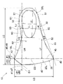
- FIG. 1 is a diagram for explaining an embodiment of the present invention, and is a plan view showing a mask in a folded state.
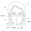
- FIG. 2 is a view shown from the front while wearing the mask of FIG. 1.
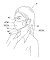
- FIG. 3 is a view shown from the side while wearing the mask of FIG. 1.
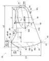
- FIG. 4 is a plan view corresponding to FIG. 1 and is a diagram showing a modified example of the mask.
- FIG. 5 is a plan view corresponding to FIG. 1 and is a diagram showing another modification of the mask.
- the mask is devised so as to have a sufficient effect on the appearance of the mask wearer.
- the mask 10 covers the mouth and nostrils of the wearer P's face.
- the mask 10 is used for the purpose of suppressing the diffusion of droplets and the like from the wearer P and suppressing the suction of foreign substances and the like by the wearer P.
- the mask 10 has a mask main body portion 20 and an ear hook portion 30.
- the mask body 20 is arranged to face the mouth and nostrils of the wearer P and covers the mouth and nostrils.
- the ear hook portion 30 includes a pair of ear hook portions 30L and 30R extending from the mask main body portion 20 to both sides.
- the left ear hook portion 30L is located on the left side and is hung on the left ear of the wearer P.
- the right ear hook portion 30R is located on the right side and is hung on the right ear of the wearer P.
- the mask body 20 is held at a position facing the wearer P's face mouth and nostrils.
- the mask main body 20 may have a single-layer structure or a multi-layer structure.
- the mask main body 20 having a plurality of layers may include the outer layer, the filter layer, and the lining layer in this order from the front to the back.
- the outer layer may have a color or texture that can exhibit the design. Further, the outer layer may have a filter function of suppressing the passage of droplets, foreign substances and the like.
- a puff material layer puff-like material layer
- the puff material layer is a material having a texture similar to that of a puff used when applying powdery cosmetics such as foundation to the skin.
- a porous layer such as a sponge using a resin such as natural rubber, synthetic rubber, polyester or nylon is exemplified.
- the non-woven fabric forming the outer material layer a non-woven fabric using a resin or fiber such as polyester or nylon is exemplified.
- the outer layer may contain a heat radiating material, a deodorant material, an antibacterial material and the like.
- the filter layer exerts a filter function and suppresses the passage of droplets and foreign substances.
- the filter layer include a non-woven fabric using a resin or fiber such as polyester or nylon, and a resin layer using urethane or the like.
- the filter layer is provided with voids that allow ventilation for breathing. However, it is preferable that this void has a size that can effectively regulate the passage of droplets such as saliva and the passage of foreign substances such as pollen and dust.
- the lining layer comes into contact with the skin of the mask wearer P, it is preferable to use a layer made of a material that is comfortable against the skin.
- textiles such as woven fabrics and non-woven fabrics are exemplified.
- non-woven fabric forming the lining layer a non-woven fabric using a resin or fiber such as polyester or nylon is exemplified.
- the lining layer may contain a heat radiating material, a deodorant material, an antibacterial material and the like.
- the lining layer may use a material different from that of the outer layer.
- the ear hook portion 30 may be integrally formed of the same material as the mask main body portion 20 without any joint.
- the ear hook 30 may be formed by any one or more layers forming the mask main body 20.
- the ear hook portion 30 may be integrally formed with any one or more layers forming the mask main body portion 20 without any joint.
- the ear hook portion 30 may be formed as a separate member from the mask main body portion 20 and attached to the mask main body portion 20.
- the ear chipped portion 30 can be formed in a sheet shape as in the illustrated example. Rubber or cloth can be used as the ear hook portion 30 which is a member separate from the mask main body portion 20.
- the ear hook portion 30 may be attached to the mask main body portion 20 by using a joining material such as an adhesive or by welding.
- the mask 10 and the mask main body 20 can be folded by bending along the bending line 40.
- the folding line 40 is not straight.
- the mask 10 and the mask body 20 have a three-dimensional shape in a state where the pair of ear hooks 30 are separated from each other and the mask 10 and the mask body 20 are spread out.
- the fold line 40 extends in a curved shape.
- the mask 10 is bent along the bending line 40 to form a flat sheet as shown in FIG. Further, in the illustrated example, the mask 10 has a symmetrical shape about the bending line 40.
- the mask 10 includes a left mask half body 10L and a right mask half body 10R separated by a bending line 40. As shown in FIG. 1, in a state where the mask 10 is folded around the folding line 40, the left mask half body 10L and the right mask half body 10R are overlapped to form a sheet.
- the left mask half body 10L and the right mask half body 10R may be integrally formed without a seam. Alternatively, the left mask half body 10L and the right mask half body 10R may be formed as separate bodies and joined at the bending line 40. The joining may be welding or sewing.
- the mask main body 20 has a symmetrical shape centered on the bending line 40.
- the mask main body 20 includes a left main body half body 20L and a right main body half body 20R separated by a bending line 40. As shown in FIG. 1, in a state where the mask 10 is folded around the bending line 40, the left main body half body 20L and the right main body half body 20R are overlapped to form a sheet.
- the left main body half body 20L and the right main body half body 20R may be integrally formed without a seam.
- the left main body half body 20L and the right main body half body 20R may be formed as separate bodies and joined at the bending line 40. The joining may be welding or sewing.
- the bending line 40 has one bending point 41.
- the bending point is a connection point of two line segments having different directions.
- this bending point is not limited to the bent point of the bending line 40, and as long as the tip of the nose can be emphasized, the two line segments are chamfered and smoothly connected. It may be a point.
- the bending point 41 is an intersection of a curved line portion and a curved line portion.
- the present invention is not limited to this example, and the bending point 41 may be an intersection of a straight line portion and a straight line portion, or may be an intersection of a curved line portion and a straight line portion.
- the folding line 40 has an upper end 42 and a lower end 43.
- the upper end 42 is the end on the side close to the eyes of the mask wearer P while wearing the mask 10.
- the lower end 43 is the end on the side close to the eyes of the mask wearer P while wearing the mask 10.
- the bending point 41 is located between the upper end 42 and the lower end 43 on the bending line 40.
- the straight line connecting the upper end 42 and the lower end 43 with respect to the mask 10 in the folded state is defined as the reference axis 45.
- the direction orthogonal to the reference axis 45 with respect to the mask 10 in the folded state is defined as the first direction D1.
- the direction parallel to the reference axis 45 with respect to the mask 10 in the folded state is defined as the second direction D2.
- the straight line portion 48 connecting the maximum protruding position 47 farthest from the reference axis 45 and the upper end 42 of the bending line 40 is relative to the reference axis 45. , Inclined.
- the maximum protruding position 47 is the position farthest from the reference axis 45 in the bending line 40 in the first direction D1.
- the angle ⁇ 1 formed by the straight line portion 48 with respect to the reference axis 45 can be 30 ° or more and 40 ° or less, and more preferably 34 ° or more and 36 ° or less.
- the straight line portion 49 connecting the upper end 42 of the folding line 40 and the bending point 41 of the folding line 40 is relative to the reference axis 45. It is tilted.
- the angle ⁇ 2 formed by the straight line portion 49 with respect to the reference axis 45 can be 30 ° or more and 40 ° or less, and more preferably 34 ° or more and 36 ° or less.
- the bending line 40 includes a plurality of bending points 41, the bending point at which the bending line 40 bends most is used to specify the angle ⁇ 2.
- the bending point at which the bending point is the largest means the bending point at which the inclination angle formed by the two line segments connected at the bending point with respect to each other is maximum.
- the portion of the mask 10 located between the reference axis 45 and the bending line 40 is the mask 10 in a state where the mask 10 is spread so as to separate the left ear hook portion 30L and the right ear hook portion 30R from each other. It is a part that is formed three-dimensionally.
- these angles ⁇ 1 and ⁇ 2 affect the inclination angle of the portion of the mask 10 that covers the nose of the wearer P. give.
- the angles ⁇ 1 and ⁇ 2 in the above range as shown in FIG. 3, when the wearer wearing the mask 10 is observed from the side, the portion located near the tip of the nose of the mask wearer P.
- the mask 10 becomes the most protruding. Then, the impression that the mask wearer P is tightened from the most protruding position toward the chin tip of the wearer P is given to the mask wearer P. As a result, the wearer P's face can be given a clean impression through the nose, that is, a neat impression. Further, since the face does not appear to be inflated, the face of the wearer P can be made to appear small.
- the mask 10 may be designed as follows in relation to the angles ⁇ 1 and ⁇ 2.
- the distance LA1 from the reference axis 45 to the maximum protrusion position 47 may be 15 mm or more and 25 mm or less. That is, the length LA1 along the first direction D1 orthogonal to the reference axis 45 from the reference axis 45 to the maximum protrusion position 47 may be 15 mm or more and 25 mm or less.
- the distance (length along the first direction D1) LA2 from the reference axis 45 to the most bent bending point 41 is 15 mm. It may be 25 mm or more and 25 mm or less.
- the length LB1 along the second direction D2 parallel to the reference axis 45 from the upper end 42 of the folding line 40 to the maximum protruding position 47. May be 25 mm or more and 30 mm or less.
- the bending point 41 is an inflection point. That is, the two line segments located on both sides of the bending point 41 and connected at the bending point 41 are inclined to the opposite sides with respect to the first direction D1. The two line segments located on both sides of the bending point 41 and connected at the bending point 41 are inclined opposite to each other with respect to the second direction D2. Therefore, in the illustrated example, the maximum protruding position 47 coincides with the bending point 41 on the bending line 40.
- the angle ⁇ 1 and the angle ⁇ 2 are the same.
- the length LA1 and the length LA2 are the same, and the length LB1 and the length LB2 are the same.
- the bending point 41 becomes an inflection point, it is possible to effectively prevent the bending line 40 from being rounded when the mask 10 is worn, and it becomes easy to maintain the bending line 40 in a bent state when observed from the side. .. That is, when the bending point 41 is an inflection point, the bending point 41 is located at the tip of the nose of the mask wearer P, so that the silhouette of the wearer P covered by the mask 10 is formed by the mask 10 and the tip of the nose protrudes. Can be effectively emphasized. Further, it is possible to give the impression that the mask 10 is tightened from the tip of the nose toward the tip of the chin. As a result, it is possible to further emphasize a clean impression through the nose, that is, a neat impression.
- the present invention is not limited to the illustrated example, and the maximum protrusion position 47 may deviate from the most bent bending point 41 on the bending line 40.
- the bending line 40 includes only a single bending point 41, but the present invention is not limited to this example, and the bending line 40 may include a plurality of bending points.
- the overall dimensions of the mask 10 do not match the dimensions of the face of the mask wearer P, a large elongation occurs in the mask 10. In this case, it is assumed that the expected three-dimensional shape of the mask 10 cannot be obtained when the mask 10 is worn. Therefore, it is preferable that the overall dimensions of the mask 10 are set in consideration of the average dimensions of the face.
- the length LC along the first direction D1 of the mask 10 is 160 mm or more and 190 mm or less.
- the length LC is more preferably 160 mm or more and 180 mm or less, and for masks for adult men, the length LC is more preferably 165 mm or more and 190 mm or less.
- the length LD from the upper end 42 to the lower end 43 of the bending line 40 along the second direction D2 shall be 110 mm or more and 135 mm or less. Is preferable.
- the length LD is more preferably 110 mm or more and 130 mm or less, and for masks for adult men, the length LD is more preferably 120 mm or more and 135 mm or less.
- the lower edge portion 50 extends from the lower end 43 of the bending line 40 in the first direction D1.
- the lower tangent line 53 is in contact with the lower edge portion 50.
- the lower tangent line 53 is in contact with the lower edge portion 50 at the lower end 43 of the bending line 40, and is in contact with the lower edge portion 50 at the lower contact portion 51 of the ear hook portion 30.
- the lower edge portion 50 is inward (upper) with respect to the lower tangent line 53 in the entire area from the lower end 43 to the lower contact 51. It is dented to be located. That is, the lower edge portion 50 is recessed so as to be located between the lower tangent line 53 and the upper edge portion 60 in the second direction D2 in the entire area from the lower end 43 to the lower contact 51.
- the lower edge portion 50 is recessed inward (upper side) so as to be concave. Therefore, when observed from the front as shown in FIG. 2, the chin line, which is the face line of the wearer P, can be easily understood. Above all, the chin line can be made to look sharp as it lifts toward the ears. Further, as shown in FIG. 3, when observed from the side, the effect of the recessed lower edge portion 50 becomes more remarkable, and the jaw line can be shown to be tightened. That is, the face of the wearer P can be made to look sharp. As a result, it is possible to make the wearer P's face look smaller without making the wearer P's face look inflated. Furthermore, the three-dimensional appearance of the worn mask 10 is emphasized by these frontal and lateral views, and the nasal muscles can be synergistically emphasized by combining with the above-mentioned settings regarding the angles ⁇ 1 and ⁇ 2. can.
- the mask 10 may be designed as follows in relation to the lower edge portion 50.
- the maximum separation distance LE of the lower edge portion 50 with respect to the lower tangent line 53 may be 2 mm or more and 10 mm or less, and further 2 mm or more and 6 mm or less. May be.
- the maximum length LE along the direction orthogonal to the lower tangent line 53 from the lower tangent line 53 to the lower edge portion 50 may be 2 mm or more and 10 mm or less, and further may be 2 mm or more and 6 mm or less.
- the position of the lower edge portion 50 farthest from the lower tangent line 53 is defined as the lower maximum recessed position 52. That is, the position on the lower edge portion 50 where the above-mentioned maximum separation distance LE can be obtained is defined as the lower maximum recessed position 52.
- the length LF along the first direction D1 from the lower maximum recess position 52 to the reference axis 45 is set to 50 mm or more and 62 mm or less. It is preferably 53 mm or more and 59 mm or less, and more preferably.
- the upper edge portion 60 of the mask 10 extends from the upper end 42 of the bending line 40 in the first direction D1.
- the upper tangent line 63 is in contact with the upper edge portion 60.
- the upper tangent line 63 is in contact with the upper edge portion 60 at the upper end 42 of the bending line 40, and is in contact with the upper edge portion 60 at the upper contact portion 61 of the ear hook portion 30.
- the upper edge portion 60 is located inside (lower side) with respect to the upper tangent line 63 in the entire area from the upper end 42 to the upper contact 61. It's dented. That is, the upper edge portion 60 is recessed so as to be located between the upper tangent line 63 and the lower edge portion 50 in the second direction D2 in the entire area from the upper end 42 to the upper contact 61.
- the maximum distance LG of the upper edge portion 60 with respect to the upper tangent line 63 is the lower edge portion 50 with respect to the above-mentioned lower tangent line 53. It is larger than the maximum separation distance LE of.
- the maximum distance LG of the upper edge 60 with respect to the upper tangent 63 is the maximum distance of the lower edge 50 with respect to the lower tangent 53.
- the distance LE is preferably 1.5 times or more and 10 times or less, more preferably 1.5 times or more and 7 times or less, and further preferably 1.5 times or more and 4 times or less.
- the maximum separation distance LG of the upper edge portion 60 with respect to the lower tangent line 53 may be 10 mm or more and 18 mm or less, and further 12 mm or more. It may be 16 mm or less.
- the maximum length LG along the direction orthogonal to the upper tangent line 63 from the upper tangent line 63 to the upper edge portion 60 may be 10 mm or more and 18 mm or less, and further may be 12 mm or more and 16 mm or less.
- the length LG By setting the length LG in these manners, as shown in FIGS. 2 and 3, in frontal and lateral observations, between the eyes of the wearer P and the upper edge 60 of the mask 10.
- the skin of the wearer P can be appropriately exposed.
- the periphery of the eyes of the wearer P is exposed, and the upper edge 60 of the mask 10 extends along the eyes.
- the eyes of the wearer P are emphasized, and the impression of eye makeup can be strengthened.
- the mask 10 can be fitted to the wearer P's face to emphasize the contour and three-dimensional effect of the face. As a result, the face of the wearer P can be made to look smaller without making the face of the wearer P look inflated.
- the position of the upper edge portion 60 farthest from the upper tangent line 63 is defined as the upper maximum recess position 62. That is, the position on the upper edge portion 60 where the above-mentioned maximum separation distance LG can be obtained is defined as the upper maximum recess position 62.
- the length LH along the first direction D1 from the upper maximum recess position 62 to the reference axis 45 shall be 47 mm or more and 59 mm or less. It is preferable, and it is more preferable that it is 50 mm or more and 56 mm or less.
- the length LH along the first direction D1 from the upper maximum recess position 62 to the reference axis 45 is shorter than the length LF along the first direction D1 from the lower maximum recess position 52 to the reference axis 45. It is preferable to do so.
- the length LH shorter than the length F, both the effect of the recessed lower edge portion 50 and the effect of the recessed upper edge portion 60 can be made more remarkable. ..
- the ear hook portion 30 will be described.
- An ear passage hole 31 is formed in the ear hook portion 30.
- the ear hook portion 30 is held by the face of the mask wearer P.
- the length LI along the first direction D1 of the ear passage hole 31 is preferably 80 mm or more and 89 mm or less, preferably 82 mm or more and 86 mm or less. It is more preferable to do so.
- the ear hook portion 30 is not a mere elastic cord, but has a thick width of, for example, 3 mm or more or 5 mm or more.
- the length LI with respect to the ear passage hole 31 is largely secured.
- this mask 10 as shown in FIG. 2, the margin portion of the face of the wearer P can be appropriately exposed from the ear passage hole 31 even when observed from the front.
- the chin line can be made to look sharp so as to be lifted toward the ear.
- the face of the wearer P can be made to look smaller without making the face of the wearer P look inflated.
- FIG. 3 in the observation from the side, the side-facing portion of the cheek of the wearer P can be largely exposed.
- the three-dimensional appearance of the worn mask 10 is emphasized by these frontal and lateral views, and the nose muscle can be synergistically emphasized by combining with the above-mentioned settings regarding the angles ⁇ 1 and ⁇ 2.
- the length LJ along the second direction D2 from the upper edge 60 to the ear passage hole 31 is shorter than the length LK along the second direction D2 from the lower edge 50 to the ear passage hole 31. ing. That is, in the ear hook portion 30, the ear passage hole 31 is separated from the lower edge portion 50 and close to the upper edge portion 60 in the second direction D2. According to such a configuration, as shown in FIG. 2, in frontal observation, it is possible to more effectively make the line of the chin of the wearer P appear sharp so as to be lifted toward the ear. Further, as shown in FIG. 3, in the observation from the side, the skin near the eyes of the wearer P, who has a good complexion, can be exposed from the ear passage hole 31, thereby giving an impression. ..
- the mask 10 described here has the skin of the mask wearer P, especially the skin with a good complexion such as under the eyes and the upper part of the cheeks, by at least one of the concave upper edge portion 60 and the large-area ear passage hole 31. Can be exposed.
- the color of the outer surface of the mask 10 having such a shape, particularly the color of the outer surface of the mask main body 20, has an R value of 230 or more and 250 or less, a G value of 173 or more and 214 or less, and a B value in the RGB color system. It is preferably in the range of 153 or more and 198 or less.
- the color of the outer surface of the mask body 20 is 13-1504 TPG, 13-1513 TPG, 13-2005 TPG, 12-1008 TPG, 12-1011 TPG, 13-1109 in the color sample book of PANTONE (registered trademark). It is preferable that the color corresponds to any one of TPG, 12-1010 TPG, 14-1219 TPG, and 14-1323 TPG.
- the color of the mask main body 20 and the color of PANTONE (registered trademark) visually determined to determine whether or not the color is a predetermined color shown in the color sample book of PANTONE (registered trademark). This is done by comparing it with the sample book.
- the color of the mask 10 selected from the above range exhibits a beauty effect such as making the face of the wearer P look bright like makeup cosmetics such as foundation, cheek, and lipstick. Since the color of the mask 10 selected from such a range is well-adapted to the skin, it is possible to give a natural complexion and happiness to the skin exposed from the mask 10. More specifically, it is possible to dispel the dullness and make the complexion of the face look bright and give a bright impression. In addition, the eyes exposed from the mask can be enhanced, in other words, the mask itself can bring about the same effect as the conventional makeup effect such as cheek and lipstick, and is excellent in terms of beauty.
- the mask 10 has a mask body portion 20 that covers at least a part of the wearer P's face, and an ear hook portion 30 that extends from the mask body portion 20. There is.
- the mask 10 can be folded by bending along a bending line 40 located at the center in the width direction. In a plan view in a folded state, the maximum protruding position 47 and the upper end 42 of the folding line 40 farthest from the reference axis 45 with respect to the reference axis 45 connecting the upper end 42 of the folding line 40 and the lower end 43 of the folding line 40.
- the straight line portion 48 connecting to and is inclined at an angle ⁇ 1 of 30 ° or more and 40 ° or less.
- the straight line portion 49 connecting the most bent bending point 41 of the bending line 40 and the upper end 42 with respect to the reference axis 45 is at an angle ⁇ 2 of 30 ° or more and 40 ° or less. It is tilted.
- the wearer P can be given the impression that the area around the tip of the nose protrudes most when observed from the side of the mask wearer P and is further tightened toward the chin. That is, it is possible to give the wearer P a clean impression through the nose.
- the wearer's face can be made smaller without making the face look inflated. In this way, the mask 10 can improve the impression and appearance of the mask wearer P.
- the mask 10 includes a mask main body portion 20 that covers at least a part of the face of the wearer P, and an ear hook portion 30 extending from the mask main body portion 20. is doing.
- the mask 10 can be folded by bending along a bending line 40 located at the center in the width direction.
- the lower contact line 53 where the lower tangent line 53 and the ear hook portion 30 are in contact with each other from the lower end 43 with respect to the lower tangent line 53 which passes through the lower end 43 of the bending line 40 and is in contact with the ear hook portion 30.
- the lower edge portion 50 up to is recessed so as to be located inside.
- the chin line of the wearer P can be made to appear sharp.
- the face of the wearer P can be made to look smaller without making the face look inflated.
- the three-dimensional effect of the mask 10 when worn is emphasized, and the wearer P's face can be given a clean impression through the nose, that is, a neat impression.
- the mask 10 shown in FIG. 1 features a configuration relating to an angle ⁇ 1 and an angle ⁇ 2 of the bending line 40, a configuration relating to a recessed lower edge portion 50, a configuration relating to a recessed upper edge portion 60, and a configuration relating to an ear passage hole 31. It was included as a typical composition. However, the mask 10 does not have to include all of these characteristic configurations, and may include, for example, only one of them, or may include two or more of them. The mask 10 can exert the above-mentioned excellent action and effect by including one or more of these four characteristic configurations. Furthermore, the mask 10 can exert the synergistic effect described above by including two or more of these four characteristic configurations.
- the shape of the ear passage hole 31 in the above-mentioned specific example is only an example, and the shape of the ear passage hole 31 can be changed, for example, as shown in FIG.
- the mask 10 shown in FIG. 4 can adopt the same configuration as the above-mentioned mask 10 described with reference to FIG. 1 except for the shape of the ear passage hole 31. That is, the mask 10 shown in FIG. 4 has a configuration relating to the angle ⁇ 1 and an angle ⁇ 2 of the bending line 40 described above, a configuration relating to the recessed lower edge portion 50 described above, and a configuration relating to the recessed upper edge portion 60 described above. May have.
- the lower edge portion 50 which is not recessed may be included.
- the mask 10 shown in FIG. 5 has a configuration relating to the angle ⁇ 1 and an angle ⁇ 2 of the bending line 40 described above, a configuration relating to the recessed upper edge portion 60 described above, and a configuration relating to the ear passage hole 31 described above. May be good.
- the direction D3 in which the inner dimension (inner width) of the ear passage hole 31 is the longest is inclined with respect to the first direction D1.
- the direction D3 of the longest inner dimension is inclined with respect to the first direction D1 so as to approach the reference axis 45 in the first direction D1 and to separate from the upper end 42 and approach the lower end 43 in the second direction D2. ..
- the direction D3 of the longest inner dimension is preferably inclined with respect to the first direction D1 at an angle ⁇ 3 of preferably 8 ° or more and 15 ° or less, and more preferably an angle ⁇ 3 of 8 ° or more and 12 ° or less.
- the ear passage hole 31 is elongated in the first direction D1.
- the direction D3 having the longest inner dimension which can be called the longitudinal direction of the ear passage hole 31, extends in the first direction D1 while being slightly inclined with respect to the first direction D1.
- the contour line 31C of such an ear passage hole 31 is formed in a curved shape, it has a minimum value of the radius of curvature on both sides in the first direction D1.
- the contour line 31C is closer to the reference axis 45 in the first direction D1 than the center position 32 in the first direction D1 of the ear passage hole 31.
- the first position 34A having the smallest radius of curvature is included on the side.
- the contour line 31C includes a second position 34B having the smallest radius of curvature on the side away from the reference axis 45 in the first direction D1 from the center position 32.
- the second straight line 35 connecting the first position 34A and the second position 34B is inclined with respect to the first direction D1.
- the second straight line portion 35 is inclined with respect to the first direction D1 so as to approach the reference axis 45 in the first direction D1 and to separate from the upper end 42 and approach the lower end 43 in the second direction D2.
- the second straight line portion 35 is preferably inclined with respect to the first direction D1 at an angle ⁇ 4 of preferably 8 ° or more and 15 ° or less, and more preferably at an angle ⁇ 4 of 8 ° or more and 12 ° or less.
- the chin line of the wearer P is more effectively lifted toward the ear when observed from both the front and the side. You can make it look sharp. As a result, the face of the wearer P can be made to look smaller without making the face of the wearer P look inflated. Further, in the observation from the side, the side-facing portion of the cheek of the wearer P can be largely exposed.
- the three-dimensional appearance of the worn mask 10 is emphasized by these frontal and lateral views, and the above-mentioned configurations with respect to the angles ⁇ 1 and ⁇ 2, the above-mentioned configuration of the recessed upper edge portion 60, and the above-mentioned ear passage. In combination with any one or more of the other configurations with respect to the hole 31, the nasal muscles can be synergistically emphasized.
- a part of the recessed upper edge portion 60 is inclined to the same side as the longest inner dimension direction D3 and the second straight line portion 35 with respect to the first direction D1. That is, a part of the upper edge portion 60 is inclined with respect to the first direction D1 so as to approach the reference axis 45 in the first direction D1 and to separate from the upper end 42 and approach the lower end 43 in the second direction D2. ing.
- the above-mentioned angle ⁇ 3 and angle ⁇ 4 are larger than the angle ⁇ x formed by a part of the upper edge portion 60 with respect to the first direction D1.
- the lower edge 50 is tilted with respect to the first direction D1 so as to approach the reference axis 45 in the first direction D1 and away from the upper end 42 and approach the lower end 43 in the second direction D2. ing.
- the angle ⁇ y formed by the lower edge portion 50 with respect to the first direction D1 is larger than the above-mentioned angles ⁇ 3 and ⁇ 4.
- the change in the magnitudes of the angles ⁇ x, the angle ⁇ 3, the angle ⁇ 4, and the angle ⁇ y from the upper end 42 to the lower end 43 in the second direction D2 is more effective due to the optical illusion, and the chin line of the wearer P is directed toward the ear. It can be made to look like it is lifted. As a result, the effect of making the wearer P's face look smaller becomes more remarkable.
- the ear passage hole 31 may have a large area.
- the length LI along the first direction D1 of the ear passage hole 31 is the length along the first direction D1 of the mask 10. It may be more than half of LC. In other words, the length LC along the first direction D1 of the mask 10 may be twice or less the length LI along the first direction D1 of the ear passage hole 31.
- the length LH along the first direction D1 from the upper maximum recess position 62 to the reference axis 45 may be 37 mm or more and 47 mm or less, and further 39 mm or more and 45 mm or less. ..
- the portion of the skin exposed from the mask 10 when observed from the front and the portion of the skin exposed from the mask 10 when observed from the side are different. Thereby, the three-dimensional effect of the worn mask 10 can be ideally emphasized.
- the LJ is shorter than the length LK along the second direction D2 from the lower edge 50 to the ear passage hole 31. According to such an example, the effect of adjusting the angle ⁇ 3 and the angle ⁇ 4 described above can be made more remarkable.
- the bending point 41 does not have to coincide with the maximum protruding position 47 on the bending line 40.
- the bending point 41 may be located above the maximum protrusion position 47.
- the bending point 41 may be located below the maximum protrusion position 47, or may be located below the maximum protrusion position 47.
- the straight line portion 49 connecting the upper end 42 of the bending line 40 and the bending point 41 of the bending line 40 is the reference axis 45.
- the angle ⁇ 2 formed by the straight line portion 49 with respect to the reference axis 45 may be 30 ° or more and 40 ° or less, and more preferably 34 ° or more and 36 ° or less.
- the straight line portion 48 connecting the upper end 42 of the bending line 40 and the maximum protruding position 47 of the bending line 40 is , Is inclined with respect to the reference axis 45.
- the angle ⁇ 1 formed by the straight line portion 48 with respect to the reference axis 45 may be 30 ° or more and 40 ° or less, and more preferably 34 ° or more and 36 ° or less. Only one of the angle ⁇ 1 and the angle ⁇ 2 may satisfy the angle condition. Both the angle ⁇ 1 and the angle ⁇ 2 may satisfy the angle condition.
- the above-mentioned effect can be obtained by such a configuration related to the angle ⁇ 1 or the angle ⁇ 2. That is, when the wearer wearing the mask 10 is observed from the side, the mask 10 is most projected at the portion located near the tip of the nose of the mask wearer P. Then, the impression that the mask wearer P is tightened from the most protruding position toward the chin tip of the wearer P is given to the mask wearer P. As a result, the wearer P's face can be given a clean impression through the nose, that is, a neat impression. Further, since the face does not appear to be inflated, the face of the wearer P can be made to appear small.
- the bending point 41 and the maximum protrusion position 47 do not match on the bending line 40.
- the distance LA2 from the reference axis 45 to the bending point 41 that is most bent is 15 mm or more. It may be 25 mm or less. That is, the length LA2 along the first direction D1 orthogonal to the reference axis 45 from the reference axis 45 to the bending point 41 that is most bent may be 15 mm or more and 25 mm or less.
- the length LB2 along the second direction D2 may be 25 mm or more and 30 mm or less.
- the distance LA1 from the reference axis 45 to the maximum protruding position 47 is 15 mm or more. It may be 25 mm or less. That is, the length LA1 along the first direction D1 orthogonal to the reference axis 45 from the reference axis 45 to the maximum protrusion position 47 may be 15 mm or more and 25 mm or less.
- the second direction from the upper end 42 of the bending line 40 to the maximum protruding position 47 in the folded state of the mask 10 in which the bending point 41 and the maximum protruding position 47 do not match on the bending line 40.
- the length LB1 along D2 may be 25 mm or more and 30 mm or less.
Landscapes
- Health & Medical Sciences (AREA)
- General Health & Medical Sciences (AREA)
- Physical Education & Sports Medicine (AREA)
- Engineering & Computer Science (AREA)
- Textile Engineering (AREA)
- Respiratory Apparatuses And Protective Means (AREA)
Abstract
マスクは、着用者の顔の少なくとも一部を覆うマスク本体部と、マスク本体部から延び出した耳掛け部と、を有している。マスクは、幅方向中心に位置する折り曲げ線で折り曲げることによって折り畳み可能となっている。折り畳まれた状態での平面視において、折り曲げ線の上端と折り曲げ線の下端とを結ぶ基準軸線に対し、基準軸線から最も離間した折り曲げ線の最大突出位置と上端とを結ぶ直線分は、30°以上40°以下の角度で傾斜している。
Description
本開示は、マスクに関する。
2020年1月頃よりCOVID-19の感染が広がっている。世界中の多くの人々は、マスク着用により感染拡大防止および感染予防を図ることを余儀なくされている。マスクについては種々の研究がなされてきたが(例えば、特許第5632149号)、マスクが日常化した今般では、新たな課題として着用者の見栄えを向上させる機能もマスクに要求され始めた。
しかしながら、従来のマスクでは着用者の見栄えに十分な影響を与えることができていない。本開示は、このような点を考慮してなされたものであって、マスクが着用者の見栄えに十分に影響を与え得るようにすることを目的とする。
本発明による第1のマスクは、
着用者の顔の少なくとも一部を覆うマスク本体部と、
前記マスク本体部から延び出した耳掛け部と、を備え、
幅方向中心に位置する折り曲げ線で折り曲げることによって折り畳み可能であり、
前記折り畳まれた状態での平面視において、着用時に前記着用者の目に接近する側となる前記折り曲げ線の上端と前記目から離間する側となる前記折り曲げ線の下端とを結ぶ基準軸線に対し、前記折り曲げ線の最も大きく屈曲した屈曲点と前記上端とを結ぶ直線分は、30°以上40°以下の角度で傾斜している。
着用者の顔の少なくとも一部を覆うマスク本体部と、
前記マスク本体部から延び出した耳掛け部と、を備え、
幅方向中心に位置する折り曲げ線で折り曲げることによって折り畳み可能であり、
前記折り畳まれた状態での平面視において、着用時に前記着用者の目に接近する側となる前記折り曲げ線の上端と前記目から離間する側となる前記折り曲げ線の下端とを結ぶ基準軸線に対し、前記折り曲げ線の最も大きく屈曲した屈曲点と前記上端とを結ぶ直線分は、30°以上40°以下の角度で傾斜している。
本発明による第1のマスクにおいて、前記折り畳まれた状態での平面視において、前記基準軸線から前記屈曲点までの距離は、15mm以上25mm以下であってもよい。
本発明による第1のマスクにおいて、前記折り畳まれた状態での平面視において、前記上端から前記屈曲点までの前記基準軸線と平行な方向に沿った長さは、25mm以上30mm以下であってもよい。
本発明による第2のマスクは、
着用者の顔の少なくとも一部を覆うマスク本体部と、
前記マスク本体部から延び出した耳掛け部と、を備え、
幅方向中心に位置する折り曲げ線で折り曲げることによって折り畳み可能であり、
前記折り畳まれた状態での平面視において、着用時に前記着用者の目に接近する側となる前記折り曲げ線の上端と前記目から離間する側となる前記折り曲げ線の下端とを結ぶ基準軸線に対し、前記基準軸線から最も離間した前記折り曲げ線の最大突出位置と前記上端とを結ぶ直線分は、30°以上40°以下の角度で傾斜している。
着用者の顔の少なくとも一部を覆うマスク本体部と、
前記マスク本体部から延び出した耳掛け部と、を備え、
幅方向中心に位置する折り曲げ線で折り曲げることによって折り畳み可能であり、
前記折り畳まれた状態での平面視において、着用時に前記着用者の目に接近する側となる前記折り曲げ線の上端と前記目から離間する側となる前記折り曲げ線の下端とを結ぶ基準軸線に対し、前記基準軸線から最も離間した前記折り曲げ線の最大突出位置と前記上端とを結ぶ直線分は、30°以上40°以下の角度で傾斜している。
本発明による第2のマスクにおいて、前記折り畳まれた状態での平面視において、前記基準軸線から前記最大突出位置までの距離は、15mm以上25mm以下であってもよい。
本発明による第2のマスクにおいて、前記折り畳まれた状態での平面視において、前記上端から前記最大突出位置までの前記基準軸線と平行な方向に沿った長さは、25mm以上30mm以下であってもよい。
本発明による第1及び第2のマスクにおいて、
前記折り畳まれた状態での平面視において、前記折り曲げ線の前記上端と前記下端とを結ぶ前記基準軸線に直交する方向を第1方向と定義し、
前記折り畳まれた状態での平面視において、前記第1方向に沿った長さは160mm以上190mm以下であってもよい。
前記折り畳まれた状態での平面視において、前記折り曲げ線の前記上端と前記下端とを結ぶ前記基準軸線に直交する方向を第1方向と定義し、
前記折り畳まれた状態での平面視において、前記第1方向に沿った長さは160mm以上190mm以下であってもよい。
本発明による第1及び第2のマスクにおいて、
前記折り畳まれた状態での平面視において、前記折り曲げ線の前記上端と前記下端とを結ぶ前記基準軸線と平行な方向を第2方向と定義し、
前記折り畳まれた状態での平面視において、前記第2方向に沿った前記上端から前記下端までの長さは110mm以上135mm以下であってもよい。
前記折り畳まれた状態での平面視において、前記折り曲げ線の前記上端と前記下端とを結ぶ前記基準軸線と平行な方向を第2方向と定義し、
前記折り畳まれた状態での平面視において、前記第2方向に沿った前記上端から前記下端までの長さは110mm以上135mm以下であってもよい。
本発明による第1及び第2のマスクにおいて、前記折り畳まれた状態での平面視において、前記折り曲げ線の前記下端を通過し前記耳掛け部に接する下側接線に対し、前記下端から前記下側接線と前記耳掛け部が接する下側接点までの下側縁部は、凹んでいてもよい。
本発明による第3のマスクは、
着用者の顔の少なくとも一部を覆うマスク本体部と、
前記マスク本体部から延び出した耳掛け部と、を備え、
幅方向中心に位置する折り曲げ線で折り曲げることによって折り畳み可能であり、
前記折り畳まれた状態での平面視において、着用時に前記着用者の目から離間する側となる前記折り曲げ線の下端を通過し前記耳掛け部に接する下側接線に対し、前記下端から前記下側接線と前記耳掛け部が接する下側接点までの下側縁部は、凹んでいる。
着用者の顔の少なくとも一部を覆うマスク本体部と、
前記マスク本体部から延び出した耳掛け部と、を備え、
幅方向中心に位置する折り曲げ線で折り曲げることによって折り畳み可能であり、
前記折り畳まれた状態での平面視において、着用時に前記着用者の目から離間する側となる前記折り曲げ線の下端を通過し前記耳掛け部に接する下側接線に対し、前記下端から前記下側接線と前記耳掛け部が接する下側接点までの下側縁部は、凹んでいる。
本発明による第1~第3のマスクにおいて、前記折り畳まれた状態での平面視において、前記下側接線に対する前記下側縁部の最大離間距離は2mm以上10mm以下であってもよい。
本発明による第1~第3のマスクにおいて、
前記折り畳まれた状態での平面視において、着用時に前記着用者の目に接近する側となる前記折り曲げ線の上端と前記折り曲げ線の前記下端とを結ぶ基準軸線に直交する方向を第1方向と定義し、
前記折り畳まれた状態での平面視において、前記下側接線から最も離間した前記下側縁部の下側最大凹み位置から前記基準軸線までの前記第1方向に沿った長さは、50mm以上62mm以下であってもよい。
前記折り畳まれた状態での平面視において、着用時に前記着用者の目に接近する側となる前記折り曲げ線の上端と前記折り曲げ線の前記下端とを結ぶ基準軸線に直交する方向を第1方向と定義し、
前記折り畳まれた状態での平面視において、前記下側接線から最も離間した前記下側縁部の下側最大凹み位置から前記基準軸線までの前記第1方向に沿った長さは、50mm以上62mm以下であってもよい。
本発明による第1~第3のマスクにおいて、
前記折り畳まれた状態での平面視において、着用時に前記着用者の目に近接する側となる前記折り曲げ線の上端を通過し前記耳掛け部に接する上側接線に対し、前記上端から前記上側接線と前記耳掛け部が接する上側接点までの上側縁部は、凹み、
前記折り畳まれた状態での平面視において、前記上側接線に対する前記上側縁部の最大離間距離は、前記下側接線に対する前記下側縁部の最大離間距離よりも大きくてもよい。
前記折り畳まれた状態での平面視において、着用時に前記着用者の目に近接する側となる前記折り曲げ線の上端を通過し前記耳掛け部に接する上側接線に対し、前記上端から前記上側接線と前記耳掛け部が接する上側接点までの上側縁部は、凹み、
前記折り畳まれた状態での平面視において、前記上側接線に対する前記上側縁部の最大離間距離は、前記下側接線に対する前記下側縁部の最大離間距離よりも大きくてもよい。
本発明による第1~第3のマスクにおいて、
前記折り畳まれた状態での平面視において、着用時に前記着用者の目に近接する側となる前記折り曲げ線の上端を通過し前記耳掛け部に接する上側接線に対し、前記上端から前記上側接線と前記耳掛け部が接する上側接点までの上側縁部は、凹み、
前記折り畳まれた状態での平面視において、前記上側接線に対する前記上側縁部の最大離間距離は、前記下側接線に対する前記下側縁部の最大離間距離の1.5倍以上10倍以下であってもよい。
前記折り畳まれた状態での平面視において、着用時に前記着用者の目に近接する側となる前記折り曲げ線の上端を通過し前記耳掛け部に接する上側接線に対し、前記上端から前記上側接線と前記耳掛け部が接する上側接点までの上側縁部は、凹み、
前記折り畳まれた状態での平面視において、前記上側接線に対する前記上側縁部の最大離間距離は、前記下側接線に対する前記下側縁部の最大離間距離の1.5倍以上10倍以下であってもよい。
本発明による第1~第3のマスクにおいて、
前記折り畳まれた状態での平面視において、着用時に前記着用者の目に近接する側となる前記折り曲げ線の上端と前記折り曲げ線の前記下端とを結ぶ基準軸線に直交する方向を第1方向と定義し、
前記折り畳まれた状態での平面視において、前記折り曲げ線の前記上端を通過し前記耳掛け部に接する上側接線に対し、前記上端から前記上側接線と前記耳掛け部が接する上側接点までの上側縁部は、凹み、
前記折り畳まれた状態での平面視において、前記上側接線から最も離間した前記上側縁部の上側最大凹み位置から前記第1方向に沿った前記基準軸線までの長さは、前記下側接線から最も離間した前記下側縁部の下側最大凹み位置から前記第1方向に沿った前記基準軸線までの長さより小さくてもよい。
本発明による第1~第3のマスクにおいて、前記マスク本体部の外面の色は、RGB表色系におけるR値が230以上250以下、G値が173以上214以下、B値が153以上198以下であってもよい。
本発明による第1~第3のマスクにおいて、
前記折り畳まれた状態での平面視において、着用時に前記着用者の目に近接する側となる前記折り曲げ線の上端を通過し前記耳掛け部に接する上側接線に対し、前記上端から前記上側接線と前記耳掛け部が接する上側接点までの上側縁部は、凹み、
前記折り畳まれた状態での平面視において、前記上側接線に対する前記上側縁部の最大離間距離は10mm以上18mm以下であってもよい。
前記折り畳まれた状態での平面視において、着用時に前記着用者の目に近接する側となる前記折り曲げ線の上端を通過し前記耳掛け部に接する上側接線に対し、前記上端から前記上側接線と前記耳掛け部が接する上側接点までの上側縁部は、凹み、
前記折り畳まれた状態での平面視において、前記上側接線に対する前記上側縁部の最大離間距離は10mm以上18mm以下であってもよい。
本発明による第1~第3のマスクにおいて、
前記折り畳まれた状態での平面視において、着用時に前記着用者の目に近接する側となる前記折り曲げ線の上端と前記折り曲げ線の前記下端とを結ぶ基準軸線に直交する方向を第1方向と定義し、
前記折り畳まれた状態での平面視において、前記折り曲げ線の前記上端を通過し前記耳掛け部に接する上側接線に対し、前記上端から前記上側接線と前記耳掛け部が接する上側接点までの上側縁部は、凹み、
前記折り畳まれた状態での平面視において、前記上側接線から最も離間した前記上側縁部の上側最大凹み位置から前記基準軸線までの前記第1方向に沿った長さは、47mm以上59mm以下であってもよい。
前記折り畳まれた状態での平面視において、着用時に前記着用者の目に近接する側となる前記折り曲げ線の上端と前記折り曲げ線の前記下端とを結ぶ基準軸線に直交する方向を第1方向と定義し、
前記折り畳まれた状態での平面視において、前記折り曲げ線の前記上端を通過し前記耳掛け部に接する上側接線に対し、前記上端から前記上側接線と前記耳掛け部が接する上側接点までの上側縁部は、凹み、
前記折り畳まれた状態での平面視において、前記上側接線から最も離間した前記上側縁部の上側最大凹み位置から前記基準軸線までの前記第1方向に沿った長さは、47mm以上59mm以下であってもよい。
本発明による第1~第3のマスクにおいて、
着用者の耳が通過する耳通過孔が形成され、
前記折り畳まれた状態での平面視において、着用時に前記着用者の目に近接する側となる前記折り曲げ線の上端と前記折り曲げ線の前記下端とを結ぶ基準軸線に直交する方向を第1方向と定義し、前記基準軸線と平行な方向を第2方向と定義し、
前記折り畳まれた状態での平面視において、前記耳通過孔の前記第1方向における中心位置よりも前記第1方向における前記基準軸線に接近する側において、上側縁部から前記耳通過孔までの第2方向に沿った長さは、下側縁部から前記耳通過孔までの第2方向に沿った長さより小さくてもよい。
着用者の耳が通過する耳通過孔が形成され、
前記折り畳まれた状態での平面視において、着用時に前記着用者の目に近接する側となる前記折り曲げ線の上端と前記折り曲げ線の前記下端とを結ぶ基準軸線に直交する方向を第1方向と定義し、前記基準軸線と平行な方向を第2方向と定義し、
前記折り畳まれた状態での平面視において、前記耳通過孔の前記第1方向における中心位置よりも前記第1方向における前記基準軸線に接近する側において、上側縁部から前記耳通過孔までの第2方向に沿った長さは、下側縁部から前記耳通過孔までの第2方向に沿った長さより小さくてもよい。
本発明による第1~第3のマスクにおいて、
着用者の耳が通過する耳通過孔が形成され、
前記折り畳まれた状態での平面視において、着用時に前記着用者の目に近接する側となる前記折り曲げ線の上端と前記折り曲げ線の前記下端とを結ぶ基準軸線に直交する方向を第1方向と定義し、前記基準軸線と平行な方向を第2方向と定義し、
前記折り畳まれた状態での平面視において、前記耳通過孔の前記第1方向における中心位置から前記第1方向に沿って前記折り畳み線に接近するにつれて、前記耳通過孔の前記第2方向に沿った長さは小さくなってもよい。
着用者の耳が通過する耳通過孔が形成され、
前記折り畳まれた状態での平面視において、着用時に前記着用者の目に近接する側となる前記折り曲げ線の上端と前記折り曲げ線の前記下端とを結ぶ基準軸線に直交する方向を第1方向と定義し、前記基準軸線と平行な方向を第2方向と定義し、
前記折り畳まれた状態での平面視において、前記耳通過孔の前記第1方向における中心位置から前記第1方向に沿って前記折り畳み線に接近するにつれて、前記耳通過孔の前記第2方向に沿った長さは小さくなってもよい。
本発明による第1~第3のマスクにおいて、
着用者の耳が通過する耳通過孔が形成され、
前記折り畳まれた状態での平面視において、着用時に前記着用者の目に近接する側となる前記折り曲げ線の上端と前記折り曲げ線の前記下端とを結ぶ基準軸線に直交する方向を第1方向と定義し、
前記折り畳まれた状態での平面視において、前記耳通過孔の前記第1方向に沿った長さは80mm以上89mm以下であってもよい。
着用者の耳が通過する耳通過孔が形成され、
前記折り畳まれた状態での平面視において、着用時に前記着用者の目に近接する側となる前記折り曲げ線の上端と前記折り曲げ線の前記下端とを結ぶ基準軸線に直交する方向を第1方向と定義し、
前記折り畳まれた状態での平面視において、前記耳通過孔の前記第1方向に沿った長さは80mm以上89mm以下であってもよい。
本発明による第1~第3のマスクにおいて、
着用者の耳が通過する耳通過孔が形成され、
前記折り畳まれた状態での平面視において、着用時に前記着用者の目に近接する側となる前記折り曲げ線の上端と前記折り曲げ線の前記下端とを結ぶ基準軸線に直交する方向を第1方向と定義し、
前記折り畳まれた状態での平面視において、前記耳通過孔の前記第1方向に沿った長さの二倍以下となる前記第1方向に沿った長さを有してもよい。
着用者の耳が通過する耳通過孔が形成され、
前記折り畳まれた状態での平面視において、着用時に前記着用者の目に近接する側となる前記折り曲げ線の上端と前記折り曲げ線の前記下端とを結ぶ基準軸線に直交する方向を第1方向と定義し、
前記折り畳まれた状態での平面視において、前記耳通過孔の前記第1方向に沿った長さの二倍以下となる前記第1方向に沿った長さを有してもよい。
本発明による第1~第3のマスクにおいて、
着用者の耳が通過する耳通過孔が形成され、
前記折り畳まれた状態での平面視において、着用時に前記着用者の目に近接する側となる前記折り曲げ線の上端と前記目から離間する側となる前記折り曲げ線の下端とを結ぶ基準軸線に直交する方向を第1方向と定義し、前記基準軸線と平行な方向を第2方向と定義し、
前記折り畳まれた状態での平面視において、前記耳通過孔の内寸法が最長となる方向は、前記第1方向において前記基準軸線に接近するにつれて前記第2方向において前記上端から離間して前記下端に接近するようにして、前記第1方向に対し8°以上15°以下の角度で傾斜してもよい。
着用者の耳が通過する耳通過孔が形成され、
前記折り畳まれた状態での平面視において、着用時に前記着用者の目に近接する側となる前記折り曲げ線の上端と前記目から離間する側となる前記折り曲げ線の下端とを結ぶ基準軸線に直交する方向を第1方向と定義し、前記基準軸線と平行な方向を第2方向と定義し、
前記折り畳まれた状態での平面視において、前記耳通過孔の内寸法が最長となる方向は、前記第1方向において前記基準軸線に接近するにつれて前記第2方向において前記上端から離間して前記下端に接近するようにして、前記第1方向に対し8°以上15°以下の角度で傾斜してもよい。
本発明による第1~第3のマスクにおいて、
着用者の耳が通過する耳通過孔が形成され、
前記折り畳まれた状態での平面視において、着用時に前記着用者の目に近接する側となる前記折り曲げ線の上端と前記目から離間する側となる前記折り曲げ線の下端とを結ぶ基準軸線に直交する方向を第1方向と定義し、前記基準軸線と平行な方向を第2方向と定義し、
前記折り畳まれた状態での平面視において、前記耳通過孔の前記第1方向における中心位置よりも前記第1方向における前記基準軸線に接近する側に位置する前記耳通過孔の輪郭線のうちの曲率半径が最も小さくなる位置と、前記耳通過孔の前記第1方向における中心位置よりも前記第1方向における前記基準軸線から離間する側に位置する前記耳通過孔の輪郭線のうちの曲率半径が最も小さくなる位置と、を結ぶ直線分は、前記第1方向において前記基準軸線に接近するにつれて前記第2方向において前記上端から離間して前記下端に接近するようにして、前記第1方向に対し8°以上15°以下の角度で傾斜してもよい。
本発明による第4のマスクは、
着用者の顔の少なくとも一部を覆うマスク本体部と、
前記マスク本体部から延び出した耳掛け部と、を備え、
着用者の耳が通過する耳通過孔が形成され、
幅方向中心に位置する折り曲げ線で折り曲げることによって折り畳み可能であり、
前記折り畳まれた状態での平面視において、着用時に前記着用者の目に近接する側となる前記折り曲げ線の上端と前記目から離間する側となる前記折り曲げ線の下端とを結ぶ基準軸線に直交する方向を第1方向と定義し、前記基準軸線と平行な方向を第2方向と定義し、
前記折り畳まれた状態での平面視において、前記耳通過孔の内寸法が最長となる方向は、前記第1方向において前記基準軸線に接近するにつれて前記第2方向において前記上端から離間して前記下端に接近するように、前記第1方向に対して傾斜する。
本発明による第5のマスクは、
着用者の顔の少なくとも一部を覆うマスク本体部と、
前記マスク本体部から延び出した耳掛け部と、を備え、
着用者の耳が通過する耳通過孔が形成され、
幅方向中心に位置する折り曲げ線で折り曲げることによって折り畳み可能であり、
前記折り畳まれた状態での平面視において、着用時に前記着用者の目に近接する側となる前記折り曲げ線の上端と前記目から離間する側となる前記折り曲げ線の下端とを結ぶ基準軸線に直交する方向を第1方向と定義し、前記基準軸線と平行な方向を第2方向と定義し、
前記折り畳まれた状態での平面視において、前記耳通過孔の前記第1方向における中心位置よりも前記第1方向における前記基準軸線に接近する側に位置する前記耳通過孔の輪郭線のうちの曲率半径が最も小さくなる位置と、前記耳通過孔の前記第1方向における中心位置よりも前記第1方向における前記基準軸線に離間する側に位置する前記耳通過孔の輪郭線のうちの曲率半径が最も小さくなる位置と、を結ぶ直線分は、前記第1方向において前記基準軸線に接近するにつれて前記第2方向において前記上端から離間して前記下端に接近するように、前記第1方向に対して傾斜する。
本発明による第1~第5のマスクにおいて、前記マスク本体部の外面の色は、PANTONE(登録商標)の色見本帳における13-1504 TPG、13-1513 TPG、13-2005 TPG、12-1008 TPG、12-1011 TPG、13-1109 TPG、12-1010 TPG、14-1219 TPG、14-1323 TPGのいずれかに該当する色でもよい。
本開示によれば、マスクの着用者の見栄えに十分に影響を与えることができる。
図面に示された具体例を参照しながら一実施の形態を以下に説明する。以下に説明する一実施の形態では、マスク着用者の見栄えに十分な影響を与え得るようにする工夫がマスクに対してなされている。
なお、本件明細書に添付する図面においては、図示と理解のしやすさの便宜上、適宜縮尺および縦横の寸法比等を、実物のそれらから変更し誇張してある。また、本明細書中において、マスク及びその構成要素に対して用いる「上」、「下」、「左」、「右」、「表」、「裏」等の用語は、特に指示がない場合、マスク着用者を基準として着用された状態での「上」、「下」、「左」、「右」、「表」、「裏」を意味する。したがって、「上」とは、上下方向において着用者の目に近接する側のことであり、「下」とは、上下方向において着用者の目から離間する側のことである。また、「裏」とは着用者に対面する側のことであり、「表」とは、着用者とは逆を向く側のことである。
図1~図3に示すように、マスク10は、着用者Pの顔のうち、口および鼻孔を覆うものである。マスク10は、着用者Pからの飛沫等の拡散抑制および着用者Pによる異物等の吸い込み抑制を目的として使用される。マスク10は、マスク本体部20及び耳掛け部30を有している。マスク本体部20は、着用者Pの口および鼻孔に対面して配置され、口および鼻孔を覆う。耳掛け部30は、マスク本体部20から両側方に延び出した一対の耳掛け部30L,30Rを含んでいる。図2及び図3に示すように、左耳掛け部30Lは、左側に位置して、着用者Pの左耳に掛けられる。図2に示すように、右耳掛け部30Rは、右側に位置して、着用者Pの右耳に掛けられる。一対の耳掛け部30が着用者Pの耳に掛けられることによって、マスク本体部20が着用者Pの顔の口および鼻孔に対面する位置に保持される。
マスク本体部20は、単層構成としてもよいし、複数層構成としてもよい。複数層構成のマスク本体部20は、表地層、フィルタ層及び裏地層を、表から裏に向けてこの順番で含むようにしてもよい。
表地層は、意匠性を発揮し得る色や質感を有していてもよい。また、表地層は、飛沫や異物等の通過を抑制するフィルタ機能を有していてもよい。表地層として、パフ素材層(パフ調材料層)や、不織布を用いることができる。パフ素材層とは、ファンデーション等の粉状の化粧品を肌に塗布する際に用いられるパフと同様の質感を有した材料である。具体的には、パフ素材として、天然ゴム、合成ゴム、ポリエステルやナイロン等の樹脂を用いたスポンジ等の多孔質層が例示される。表地層をなす不織布として、ポリエステルやナイロン等の樹脂や繊維を用いた不織布が例示される。また、表地層は、放熱材料、防臭材料、抗菌材料等を含んでいてもよい。
フィルタ層は、フィルタ機能を発現し、飛沫や異物等の通過を抑制する。フィルタ層として、ポリエステルやナイロン等の樹脂や繊維を用いた不織布、ウレタン等を用いた樹脂層が例示される。フィルタ層には、呼吸のための通気を可能とする空隙が設けられている。ただし、この空隙は、唾液等の飛沫の通過や、花粉や埃等の異物の通過を有効に規制し得る大きさとなっていることが好ましい。
裏地層は、マスク着用者Pの肌に接触するので、肌当たりの良い材料を用いた層とすることが好ましい。裏地層として、織地等のテキスタイルや不織布が例示される。裏地層をなす不織布として、ポリエステルやナイロン等の樹脂や繊維を用いた不織布が例示される。また、裏地層は、放熱材料、防臭材料、抗菌材料等を含んでいてもよい。裏地層は、表地層とは異なる素材を使用してもよい。
耳掛け部30は、マスク本体部20と同一の材料により、繋ぎ目無しで一体的に形成されていてもよい。マスク本体部20が複数層を含む場合には、耳掛け部30は、マスク本体部20をなすいずれか一以上の層によって形成されていてもよい。この例において、耳掛け部30は、マスク本体部20をなすいずれか一以上の層と繋ぎ目無しで一体的に形成されていてもよい。或いは、耳掛け部30は、マスク本体部20と別部材として形成され、マスク本体部20に取り付けられていてもよい。このような例によれば、図示された例のように耳欠け部30をシート状に形成し得る。マスク本体部20とは別部材の耳掛け部30として、ゴムや布を用いることができる。耳掛け部30のマスク本体部20への取り付けは、接着材等の接合材を用いてよいし、溶着としてもよい。
図1に示すように、マスク10及びマスク本体部20は、折り曲げ線40で折り曲げることによって折り畳み可能となっている。折り曲げ線40は直線状でない。これにより、一対の耳掛け部30を互いから離間させてマスク10及びマスク本体部20を広げた状態において、マスク10及びマスク本体部20は立体的な形状を有する。図示された例において、折り曲げ線40は曲線状に延びている。
図示された例において、マスク10は、折り曲げ線40で折り曲げられることによって、図1に示すように平坦なシート状となる。また図示された例において、マスク10は、折り曲げ線40を中心として左右対称な形状を有している。マスク10は、折り曲げ線40によって区分けされる左マスク半体10L及び右マスク半体10Rを含んでいる。図1に示すように、折り曲げ線40を中心としてマスク10を折り畳んだ状態において、左マスク半体10L及び右マスク半体10Rは重ねられて、シート状となる。左マスク半体10L及び右マスク半体10Rは、継ぎ目無しで一体的に形成されてもよい。或いは、左マスク半体10L及び右マスク半体10Rは、別体として形成され、折り曲げ線40において接合されていてもよい。接合は、溶着でもよいし、縫い付けでもよい。
同様に、マスク本体部20は、折り曲げ線40を中心として左右対称な形状を有している。マスク本体部20は、折り曲げ線40によって区分けされる左本体部半体20L及び右本体部半体20Rを含んでいる。図1に示すように、折り曲げ線40を中心としてマスク10を折り畳んだ状態において、左本体部半体20L及び右本体部半体20Rは重ねられて、シート状となる。左本体部半体20L及び右本体部半体20Rは、継ぎ目無しで一体的に形成されてもよい。或いは、左本体部半体20L及び右本体部半体20Rは、別体として形成され、折り曲げ線40において接合されていてもよい。接合は、溶着でもよいし、縫い付けでもよい。
図1に示すように、折り曲げ線40は、一つの屈曲点41を有している。ここで屈曲点とは、向きが異なる二つの線分の接続点である。ただし、この屈曲点は、厳密な意味にて折り曲げ線40のうちの折れ曲がっている点のみに限られず、鼻先を強調することができる限りにおいて、面取りがなされて滑らかに二つの線分が接続する点であってもよい。図1に示された平面視において、屈曲点41は、曲線分と曲線分との交点となっている。ただし、この例に限られず、屈曲点41は、直線分と直線分との交点であってもよいし、曲線分と直線分との交点であってもよい。
以下、マスク10の折り畳んだ状態の構成、及び、当該構成によって得られる作用効果について、更に詳述していく。
図1に示すように、折り曲げ線40は、上端42及び下端43を有している。上端42は、マスク10を着用した状態で、マスク着用者Pの目に近接する側の端である。下端43は、マスク10を着用した状態で、マスク着用者Pの目に近接する側の端である。屈曲点41は、折り曲げ線40上における上端42及び下端43の間に位置している。図1に示すように、折り畳まれた状態のマスク10に対し、上端42及び下端43を結ぶ直線を基準軸線45と定義する。更に、折り畳まれた状態のマスク10に対し、基準軸線45と直交する方向を第1方向D1と定義する。折り畳まれた状態のマスク10に対し、基準軸線45と平行な方向を第2方向D2と定義する。
図1に示された折り畳まれた状態でのマスク10の平面視において、基準軸線45から最も離間した最大突出位置47と折り曲げ線40の上端42とを結ぶ直線分48は、基準軸線45に対し、傾斜している。ここで、最大突出位置47は、折り曲げ線40のうちの基準軸線45から第1方向D1に最も離間した位置である。直線分48が基準軸線45に対してなす角度θ1は、30°以上40°以下とすることができ、より好ましくは34°以上36°以下とすることができる。
同様に、図1に示された折り畳まれた状態でのマスク10の平面視において、折り曲げ線40の上端42と折り曲げ線40の屈曲点41とを結ぶ直線分49は、基準軸線45に対し、傾斜している。直線分49が基準軸線45に対してなす角度θ2は、30°以上40°以下とすることができ、より好ましくは34°以上36°以下とすることができる。なお、折り曲げ線40が複数の屈曲点41を含む場合には、角度θ2の特定に、折り曲げ線40が最も大きく屈曲する屈曲点を用いる。最も大きく屈曲する屈曲点とは、当該屈曲点で接続する二つの線分が互いに対してなす傾斜角度が最大となる屈曲点を意味する。
マスク10のうちの基準軸線45と折り曲げ線40との間に位置する部分は、左耳掛け部30L及び右耳掛け部30Rを互いから離間するようにマスク10を広げた状態において、マスク10を立体的に形成する部分である。そして、図3から理解され得るように、マスク10が着用者Pに着用された状態において、これらの角度θ1,θ2は、マスク10のうちの着用者Pの鼻を覆う部分の傾斜角度に影響を与える。そして、角度θ1,θ2を上述の範囲に設定することによって、図3に示すように、マスク10を着用した着用者を側方から観察した場合に、マスク着用者Pの鼻先辺りに位置する部分においてマスク10が最も突出するようになる。そして、最も突出した位置から着用者Pの顎先に向かって締まる印象が、マスク着用者Pに付与される。これにより、鼻筋が通ってすっきりとした印象を、すなわち端整な印象を、着用者Pの顔に持たせることができる。また、顔を膨張した感じに見せることがないので、着用者Pの顔を小さく見せることもできる。
また、角度θ1,θ2に関連して、次のようにマスク10を設計してもよい。
図1に示された折り畳まれた状態でのマスク10の平面視において、基準軸線45から最大突出位置47までの距離LA1を、15mm以上25mm以下としてもよい。すなわち、基準軸線45から最大突出位置47までの基準軸線45と直交する第1方向D1に沿った長さLA1を15mm以上25mm以下としてもよい。同様に、図1に示された折り畳まれた状態でのマスク10の平面視において、基準軸線45から最も大きく屈曲した屈曲点41までの距離(第1方向D1に沿った長さ)LA2を15mm以上25mm以下としてもよい。長さLA1,LA2をこのように設定することによって、上述した角度θ1,θ2による作用効果をより顕著とすることができる。
また、図1に示された折り畳まれた状態でのマスク10の平面視において、折り曲げ線40の上端42から最大突出位置47までの基準軸線45と平行な第2方向D2に沿った長さLB1を、25mm以上30mm以下としてもよい。同様に、図1に示された折り畳まれた状態でのマスク10の平面視において、折り曲げ線40の上端42から最も大きく屈曲した屈曲点41までの第2方向D2に沿った長さLB2を、25mm以上30mm以下としてもよい。長さLB1,LB2をこのように設定することによって、上述した角度θ1,θ2による作用効果をより顕著とすることができる。
なお、図示された例において、屈曲点41は、変曲点となっている。すなわち、屈曲点41の両側に位置し屈曲点41で接続する二つの線分は、第1方向D1に対して互いに逆側に傾斜している。屈曲点41の両側に位置し屈曲点41で接続する二つの線分は、第2方向D2に対して互いに逆側に傾斜している。したがって、図示された例では、折り曲げ線40上において、最大突出位置47は、屈曲点41と一致している。図示された例において、角度θ1と角度θ2は同一である。また図示された例において、長さLA1及び長さLA2は同一であり、長さLB1及び長さLB2は同一である。
屈曲点41が変曲点となる場合、マスク10の着用時に折り曲げ線40が丸くなってしまうことを効果的に回避し、側方からの観察において折り曲げ線40を屈曲した状態に維持し易くなる。すなわち、屈曲点41が変曲点となる場合、マスク着用者Pの鼻先に屈曲点41が位置することにより、マスク10によって覆われた着用者Pのシルエットをマスク10によって形成し、鼻先の突出を効果的に強調することができる。更に、マスク10が鼻先からの顎先に向かって引き締まる印象を付与することができる。これにより、鼻筋が通ってすっきりとした印象を、すなわち端整な印象を、より強調することができる。
ただし、図示された例に限られず、折り曲げ線40上において、最大突出位置47は、最も大きく屈曲した屈曲点41からずれていてもよい。また、図示された例において、折り曲げ線40は単一の屈曲点41のみを含んでいるが、この例に限られず、折り曲げ線40が複数の屈曲点を含んでいてもよい。
また、マスク10の全体的な寸法がマスク着用者Pの顔の寸法に合致していないと、マスク10に大きな伸びが発生する。この場合、マスク10の着用時に、期待されたマスク10の立体形状が得られないことも想定される。そこで、マスク10の全体的な寸法は、顔の平均的な寸法を考慮して設定されていることが好ましい。
具体的には、図1に示された折り畳まれた状態でのマスク10の平面視において、マスク10の第1方向D1に沿った長さLCを160mm以上190mm以下とすることが好ましい。とりわけ、成人女性用のマスクについては長さLCを160mm以上180mm以下とすることがより好ましく、成人男性用のマスクについては長さLCを165mm以上190mm以下とすることがより好ましい。また、図1に示された折り畳まれた状態でのマスク10の平面視において、第2方向D2に沿った折り曲げ線40の上端42から下端43までの長さLDを110mm以上135mm以下とすることが好ましい。とりわけ、成人女性用のマスクについては長さLDを110mm以上130mm以下とすることがより好ましく、成人男性用のマスクについては長さLDを120mm以上135mm以下とすることがより好ましい。このように長さLC及びLDを設定することにより、着用者されたマスク10の立体感が理想的に強調される。これにより、鼻筋が通って着用者Pの顔にすっきりとした印象をより効果的に持たせることができる。
次に、マスク10の下側縁部50について説明する。下側縁部50は、折り曲げ線40の下端43から第1方向D1に延び出している。図1に示された折り畳まれた状態でのマスク10の平面視において、下側縁部50に対して下側接線53が接している。下側接線53は、折り曲げ線40の下端43で下側縁部50に接し、且つ、耳掛け部30の下側接点51で下側縁部50に接している。図1に示された折り畳まれた状態でのマスク10の平面視において、下側縁部50は、下端43から下側接点51までの全域において、下側接線53に対して内側(上側)に位置するよう凹んでいる。すなわち、下側縁部50は、下端43から下側接点51までの全域において、第2方向D2において下側接線53と上側縁部60との間に位置するように凹んでいる。
特許第5632149号に開示された従来のマスクでは、下側縁部が外側(下側)に向けて突出していた。このような従来のマスクを着用した場合、顎のラインがマスクによってすっかり覆われる。そして、顎のラインがわかりにくく、顔が膨張して見えることもあった。
これに対して、本実施の形態によれば、下側縁部50は内側(上側)に凹となるように凹んでいる。したがって、図2に示すように正面から観察した際に、着用者Pのフェイスラインである顎のラインをわかりやすくすることができる。とりわけ、顎のラインが耳に向けて持ち上がるようにシャープに見せることができる。さらに、図3に示すように側方から観察した際には、凹んだ下側縁部50による効果がより顕著となり、顎のラインを引き締めて見せることができる。つまり、着用者Pの顔をシャープに見せることができる。結果として、着用者Pの顔を膨張した感じに見せず、着用者Pの顔を小さく見せることもできる。更に、これららの正面および側方からの見え方により、着用者されたマスク10の立体感が強調され、上述の角度θ1、θ2に関する設定との組合せにより、相乗的に鼻筋を強調させることもできる。
また、下側縁部50に関連して、次のようにマスク10を設計してもよい。
まず、図1に示された折り畳まれた状態でのマスク10の平面視において、下側接線53に対する下側縁部50の最大離間距離LEを2mm以上10mm以下としてもよく、更に2mm以上6mm以下としてもよい。言い換えると、下側接線53から下側縁部50までの下側接線53に直交する方向に沿った最大長さLEを2mm以上10mm以下としてもよく、更に2mm以上6mm以下としてもよい。長さLEをこのように設定することによって、着用者Pの顎のラインをより効果的に強調することができ、上述の凹んだ下側縁部50による作用効果をより顕著とすることができる。
また、図1に示された折り畳まれた状態でのマスク10の平面視において、下側接線53から最も離間した下側縁部50の位置を下側最大凹み位置52とする。すなわち、上述の最大離間距離LEが得られる下側縁部50上の位置を下側最大凹み位置52とする。図1に示された折り畳まれた状態でのマスク10の平面視において、この下側最大凹み位置52から基準軸線45までの第1方向D1に沿った長さLFを、50mm以上62mm以下とすることが好ましく、53mm以上59mm以下とすることがより好ましい。長さLFをこのように設定することによって、顎のラインを十分な長さにわたって見せることができ、上述の凹んだ下側縁部50による作用効果をより顕著とすることができる。
次に、マスク10の上側縁部60について説明する。上側縁部60は、折り曲げ線40の上端42から第1方向D1に延び出している。図1に示された折り畳まれた状態でのマスク10の平面視において、上側縁部60に対して上側接線63が接している。上側接線63は、折り曲げ線40の上端42で上側縁部60に接し、且つ、耳掛け部30の上側接点61で上側縁部60に接している。図1に示された折り畳まれた状態でのマスク10の平面視において、上側縁部60は、上端42から上側接点61までの全域において、上側接線63に対して内側(下側)に位置するよう凹んでいる。すなわち、上側縁部60は、上端42から上側接点61までの全域において、第2方向D2において上側接線63と下側縁部50との間に位置するように凹んでいる。
とりわけ図示されたマスク10では、図1に示された折り畳まれた状態の平面視において、上側接線63に対する上側縁部60の最大離間距離LGは、上述した下側接線53に対する下側縁部50の最大離間距離LEよりも大きくなっている。
具体的には、図1に示された折り畳まれた状態のマスク10の平面視において、上側接線63に対する上側縁部60の最大離間距離LGを下側接線53に対する下側縁部50の最大離間距離LEの1.5倍以上10倍以下とすることが好ましく、1.5倍以上7倍以下にすることがより好ましく、1.5倍以上4倍以下にすることが更に好ましい。
更に具体的には、図1に示された折り畳まれた状態のマスク10の平面視において、下側接線53に対する上側縁部60の最大離間距離LGを10mm以上18mm以下としてもよく、更に12mm以上16mm以下としてもよい。言い換えると、上側接線63から上側縁部60までの上側接線63に直交する方向に沿った最大長さLGを10mm以上18mm以下としてもよく、更に12mm以上16mm以下としてもよい。
長さLGをこれらのように設定することによって、図2及び図3に示すように、正面および側方からの観察において、着用者Pの目とマスク10の上側縁部60との間に、着用者Pの肌を適度に露出させることができる。結果として、着用者Pの目の周囲が露出し、且つ、マスク10の上側縁部60が目に沿って延びるようになる。これにより、着用者Pの目が強調され、アイメイクの印象を強くすることができる。また、マスク10が着用者Pの顔にフィットして顔の輪郭や立体感を強調することができる。これにより、着用者Pの顔を膨張した感じに見せず、着用者Pの顔を小さく見せることもできる。
図1に示された折り畳まれた状態でのマスク10の平面視において、上側接線63から最も離間した上側縁部60の位置を上側最大凹み位置62とする。すなわち、上述の最大離間距離LGが得られる上側縁部60上の位置を上側最大凹み位置62とする。図1に示された折り畳まれた状態でのマスク10の平面視において、この上側最大凹み位置62から基準軸線45までの第1方向D1に沿った長さLHを、47mm以上59mm以下とすることが好ましく、50mm以上56mm以下とすることがより好ましい。長さLHをこのように設定することによって、上側縁部60が目の下側輪郭に沿って延びるようになり、上述の凹んだ上側縁部60による作用効果をより顕著とすることができる。
また、上側最大凹み位置62から基準軸線45までの第1方向D1に沿った長さLHを、下側最大凹み位置52から基準軸線45までの第1方向D1に沿った長さLFより、短くすることが好ましい。長さLHを長さFよりも短くすることにより、上述の凹んだ下側縁部50による作用効果と上述の凹んだ上側縁部60による作用効果との両方を、より顕著とすることができる。
次に、耳掛け部30について説明する。耳掛け部30には、耳通過孔31が形成されている。耳通過孔31に耳を通過させることによって、耳掛け部30がマスク着用者Pの顔に保持されるようになる。図1に示された折り畳まれた状態でのマスク10の平面視において、耳通過孔31の第1方向D1に沿った長さLIを80mm以上89mm以下とすることが好ましく、82mm以上86mm以下とすることがより好ましい。図示された例において、耳掛け部30は、単なるゴム紐ではなく、例えば3mm以上又は5mm以上の太い幅を有している。図示された例では、このようなマスク10において、耳通過孔31に関する長さLIを大きく確保している。このマスク10によれば、図2に示すように、正面からの観察においても、着用者Pの顔の余白部分を耳通過孔31から適度に露出させることができる。このとき、図1に示すように、顎のラインが耳に向けて持ち上がるようにシャープに見せることができる。これにより、着用者Pの顔を膨張した感じに見せず、着用者Pの顔を小さく見せることもできる。更に、図3に示すように、側方からの観察において、着用者Pの頬のうちの側方を向く部分を大きく露出させることができる。これららの正面および側方からの見え方により、着用者されたマスク10の立体感が強調され、上述の角度θ1、θ2に関する設定との組合せにより、相乗的に鼻筋を強調させることもできる。
また、図1に示された折り畳まれた状態でのマスク10の平面視において、耳通過孔31の第1方向D1における中心位置32よりも第1方向D1における基準軸線45に接近する側において、上側縁部60から耳通過孔31までの第2方向D2に沿った長さLJは、下側縁部50から耳通過孔31までの第2方向D2に沿った長さLKよりも、短くなっている。すなわち、耳掛け部30において耳通過孔31は、第2方向D2において、下側縁部50から離間し且つ上側縁部60に近接している。このような構成によれば、図2に示すように、正面からの観察において、より効果的に、着用者Pの顎のラインが耳に向けて持ち上がるようにシャープに見せることができる。また、図3に示すように、側方からの観察において、着用者Pの血色の良い目近傍の肌を、耳通過孔31から、露出させることもでき、これにより、印象を上げることができる。
さらに、図1に示された折り畳まれた状態でのマスク10の平面視において、耳通過孔31の第1方向D1における中心位置32から第1方向D1に沿って折り曲げ線40に接近するにつれて、耳通過孔31の第2方向D2に沿った長さLLは短くなる。このような構成によれば、図2に示すように、正面からの観察において、より効果的に、着用者Pの顎のラインが耳に向けて持ち上がるようにシャープに見せることができる。
ところで、ここで説明してきたマスク10は、凹んだ上側縁部60および大面積の耳通過孔31の少なくとも一方によって、マスク着用者Pの肌、とりわけ目の下や頬の上部等の血色の良い肌を露出させることができる。このような形状を有したマスク10の外面の色は、とりわけマスク本体部20の外面の色は、RGB表色系におけるR値が230以上250以下、G値が173以上214以下、B値が153以上198以下となる範囲内にあることが好ましい。また、マスク本体部20の外面の色は、PANTONE(登録商標)の色見本帳における13-1504 TPG、13-1513 TPG、13-2005 TPG、12-1008 TPG、12-1011 TPG、13-1109 TPG、12-1010 TPG、14-1219 TPG、14-1323 TPGのいずれかに該当する色であることが好ましい。なお、PANTONE(登録商標)の色見本帳に示された所定の色であるか否かの判断は、次に説明するように、目視したマスク本体部20の色とPANTONE(登録商標)の色見本帳とを照らし合わせることで行う。具体的には、室内において、15人が、マスク本体部20の色を目視し、PANTONE(登録商標)の色見本帳のどの色に該当するのか判断する。そして、最も多くの人が選んだ色見本帳の色が、マスク本体部20の色であると判断する。
以上のような範囲から選択されたマスク10の色は、ファンデーション、チーク、口紅等のメーキャップ化粧品と同様に着用者Pの顔を明るく映えて見せる等の美容効果を発現する。そして、このような範囲から選択されたマスク10の色は、肌へのなじみが良いことから、マスク10から露出した肌に自然な血色感や幸福感を与えることができる。より具体的には、くすみ感を払拭して顔の血色がよく明るく見せることができ、明るい印象を与えることができる。また、マスクから露出した目元を引き立てることができ、言い換えれば、マスク自体が従来のチークや口紅といったメーキャップ効果と同様の効果をもたらすことができ、美容面において優れる。
以上に説明してきた一実施の形態において、マスク10は、着用者Pの顔の少なくとも一部を覆うマスク本体部20と、マスク本体部20から延び出した耳掛け部30と、を有している。マスク10は、幅方向中心に位置する折り曲げ線40で折り曲げることによって折り畳み可能となっている。折り畳まれた状態での平面視において、折り曲げ線40の上端42と折り曲げ線40の下端43とを結ぶ基準軸線45に対し、基準軸線45から最も離間した折り曲げ線40の最大突出位置47と上端42とを結ぶ直線分48は、30°以上40°以下の角度θ1で傾斜している。或いは、折り畳まれた状態での平面視において、基準軸線45に対し、折り曲げ線40の最も大きく屈曲した屈曲点41と上端42とを結ぶ直線分49は、30°以上40°以下の角度θ2で傾斜している。このような一実施の形態によれば、マスク着用者Pの側方から観察した際に鼻先辺りが最も突出し、更に顎に向かって締まる印象を着用者Pに付与することができる。すなわち、鼻筋が通ってすっきりとした印象を着用者Pの顔に持たせることができる。また、顔を膨張した感じに見せず、着用者の顔を小さく見せることもできる。このようにマスク10によって、マスク着用者Pの印象や見栄えを向上させることができる。
また、以上に説明してきた一実施の形態において、マスク10は、着用者Pの顔の少なくとも一部を覆うマスク本体部20と、マスク本体部20から延び出した耳掛け部30と、を有している。マスク10は、幅方向中心に位置する折り曲げ線40で折り曲げることによって折り畳み可能となっている。折り畳まれた状態での平面視において、折り曲げ線40の下端43を通過し耳掛け部30に接する下側接線53に対し、下端43から下側接線53と耳掛け部30が接する下側接点51までの下側縁部50は、内側に位置するように凹んでいる。このような一実施の形態によれば、着用者Pの顎のラインをシャープに見せることができる。これにより、顔を膨張した感じに見せず、着用者Pの顔を小さく見せることもできる。また、着用時におけるマスク10の立体感が強調され、鼻筋が通ってすっきりとした印象を、すなわち端整な印象を、着用者Pの顔に持たせることができる。
一実施の形態を複数の具体例を参照しながら説明してきたが、具体例は一実施の形態を限定しない。上述した一実施の形態は、その他の様々な具体例で実施されることが可能であり、その要旨を逸脱しない範囲で、種々の省略、置き換え、変更、追加等を行うことができる。
以下、図面を参照しながら、変形の一例について説明する。以下の説明および以下の説明で用いる図面では、上述した具体例と同様に構成され得る部分について、上述の具体例における対応する部分に対して用いた符号と同一の符号を用いるとともに、重複する説明を省略する。
図1に示されたマスク10は、折り曲げ線40の角度θ1及び角度θ2に関する構成、凹んだ下側縁部50に関する構成、凹んだ上側縁部60、及び、耳通過孔31に関する構成を、特徴的な構成として含んでいた。しかしながら、マスク10は、これらの特徴的な構成をすべて含んでいる必要はなく、例えばいずれか一つのみを含んでいてもよいし、二以上を含んでいてもよい。マスク10は、これらの四つの特徴的な構成の一以上を含むことで上述した優れた作用効果を奏することができる。更に、マスク10は、これらの四つの特徴的な構成の二以上を含むことで上述した相乗的な効果を奏することができる。
例えば、上述した具体例における耳通過孔31の形状は一例に過ぎず、例えば図4に示すように、耳通過孔31の形状を変更することができる。図4に示されたマスク10は、耳通過孔31の形状を除き、図1を参照して説明した上述のマスク10と同様の構成を採用することができる。すなわち、図4に示されたマスク10は、上述した折り曲げ線40の角度θ1及び角度θ2に関する構成、上述した凹んだ下側縁部50に関する構成、及び、上述した凹んだ上側縁部60に関する構成を有していてもよい。
また、図5に示すように、凹んでいない下側縁部50を含んでいてもよい。図5に示されたマスク10は、上述した折り曲げ線40の角度θ1及び角度θ2に関する構成、上述した凹んだ上側縁部60に関する構成、及び、上述した耳通過孔31に関する構成を有していてもよい。
ところで、図5に示された例では、耳通過孔31の内寸法(内幅)が最長となる方向D3は、第1方向D1に対して傾斜している。最長内寸法の方向D3は、第1方向D1において基準軸線45に接近するにつれて第2方向D2において上端42から離間して下端43に接近するように、第1方向D1に対して傾斜している。最長内寸法の方向D3は、好ましくは、好ましくは8°以上15°以下の角度θ3で、より好ましくは8°以上12°以下の角度θ3で、第1方向D1に対して傾斜している。
同様に、図5に示された例では、耳通過孔31は第1方向D1に長細くなっている。上述したように、耳通過孔31の長手方向とも呼べる最長内寸法の方向D3は、第1方向D1に対して僅かに傾斜しつつも、第1方向D1に延びている。このような耳通過孔31の輪郭線31Cは、曲線状に形成された場合、第1方向D1における両側において曲率半径の極小値を有する。図5に示された折り畳まれた状態でのマスク10の平面視において、輪郭線31Cは、耳通過孔31の第1方向D1における中心位置32よりも第1方向D1における基準軸線45に接近する側に曲率半径が最も小さくなる第1位置34Aを含む。同様に、輪郭線31Cは、中心位置32よりも第1方向D1における基準軸線45から離間する側に曲率半径が最も小さくなる第2位置34Bを含んでいる。
図5に示すように、第1位置34A及び第2位置34Bを結ぶ第2直線分35は、第1方向D1に対して傾斜している。第2直線分35は、第1方向D1において基準軸線45に接近するにつれて第2方向D2において上端42から離間して下端43に接近するように、第1方向D1に対して傾斜している。第2直線分35は、好ましくは、好ましくは8°以上15°以下の角度θ4で、より好ましくは8°以上12°以下の角度θ4で、第1方向D1に対して傾斜している。
最長内寸法の方向D3及び第2直線分35に関する以上の構成によれば、正面及び側面の両方からの観察において、より効果的に、着用者Pの顎のラインが耳に向けて持ち上がるようにシャープに見せることができる。これにより、着用者Pの顔を膨張した感じに見せず、着用者Pの顔を小さく見せることもできる。また、側方からの観察において、着用者Pの頬のうちの側方を向く部分を大きく露出させることができる。これららの正面および側方からの見え方により、着用者されたマスク10の立体感が強調され、上述の角度θ1、θ2に関する構成、上述の凹んだ上側縁部60の構成、上述の耳通過孔31に関する他の構成のいずれか一以上との組合せにより、相乗的に鼻筋を強調させることもできる。
なお、図5に示された例において、凹んだ上側縁部60の一部分は、第1方向D1に対して、最長内寸法の方向D3及び第2直線分35と同じ側に傾斜している。すなわち、上側縁部60の一部分は、第1方向D1において基準軸線45に接近するにつれて第2方向D2において上端42から離間して下端43に接近するように、第1方向D1に対して傾斜している。この上側縁部60の一部分が第1方向D1に対してなす角度θxより、上述の角度θ3及び角度θ4は大きくなっている。同様に、下側縁部50は、第1方向D1において基準軸線45に接近するにつれて第2方向D2において上端42から離間して下端43に接近するように、第1方向D1に対して傾斜している。そして、下側縁部50が第1方向D1に対してなす角度θyは、上述の角度θ3及び角度θ4は大きくなっている。第2方向D2における上端42から下端43に向けた角度θx、角度θ3、角度θ4、角度θyの大きさの変化は、錯視により、より効果的に、着用者Pの顎のラインが耳に向けて持ち上がるように見せることができる。これにより、着用者Pの顔を小さく見せる効果がより顕著となる。
また、図5に示されたマスク10のように、耳通過孔31を大面積化してもよい。例えば、図5に示された折り畳まれた状態でのマスク10の平面視において、耳通過孔31の第1方向D1に沿った長さLIを、マスク10の第1方向D1に沿った長さLCの半分以上としてもよい。言い換えると、マスク10の第1方向D1に沿った長さLCを、耳通過孔31の第1方向D1に沿った長さLIの二倍以下としてもよい。このように耳通過孔31を大面積化することにより、角度θ3及び角度θ4に関連した上述の作用効果をより顕著とすることができる。
なお、図5に示された例では、上側最大凹み位置62から基準軸線45までの第1方向D1に沿った長さLHを、37mm以上47mm以下としてもよく、さら39mm以上45mm以下としてもよい。この例によれば、正面からの観察においてマスク10から露出する肌の部分と、側方からの観察においてマスク10から露出する肌の部分とが異なる。これにより、着用者されたマスク10の立体感を理想的に強調することができる。
なお、図5に示された例でも、中心位置32よりも第1方向D1における基準軸線45に接近する側において、上側縁部60から耳通過孔31までの第2方向D2に沿った長さLJは、下側縁部50から耳通過孔31までの第2方向D2に沿った長さLKよりも、短くなっている。このような例によれば、上述した角度θ3及び角度θ4を調整することの作用効果をより顕著とすることができる。
さらに別の変形例として、折り曲げ線40上において、屈曲点41は最大突出位置47と一致していなくてもよい。例えば、図1、図4または図5に示されたマスク10において、屈曲点41は最大突出位置47の上方に位置していてもよい。図1、図4または図5に示されたマスク10において、屈曲点41は最大突出位置47の下方に位置していてもよいし、
屈曲点41と最大突出位置47が折り曲げ線40上で一致していないマスク10の平面視において、折り曲げ線40の上端42と折り曲げ線40の屈曲点41とを結ぶ直線分49は、基準軸線45に対し、傾斜している。直線分49が基準軸線45に対してなす角度θ2は、30°以上40°以下としてもよく、より好ましくは34°以上36°以下としてもよい。同様に、屈曲点41と最大突出位置47が折り曲げ線40上で一致していないマスク10の平面視において、折り曲げ線40の上端42と折り曲げ線40の最大突出位置47とを結ぶ直線分48は、基準軸線45に対し、傾斜している。直線分48が基準軸線45に対してなす角度θ1は、30°以上40°以下としてもよく、より好ましくは34°以上36°以下としてもよい。角度θ1および角度θ2の一方だけが、角度条件を満たすようにしてもよい。角度θ1および角度θ2の一両方が、角度条件を満たすようにしてもよい。
このような角度θ1または角度θ2に関連した構成によれは、上述した効果が得られる。すなわち、マスク10を着用した着用者を側方から観察した場合に、マスク着用者Pの鼻先辺りに位置する部分においてマスク10が最も突出するようになる。そして、最も突出した位置から着用者Pの顎先に向かって締まる印象が、マスク着用者Pに付与される。これにより、鼻筋が通ってすっきりとした印象を、すなわち端整な印象を、着用者Pの顔に持たせることができる。また、顔を膨張した感じに見せることがないので、着用者Pの顔を小さく見せることもできる。
屈曲点41と最大突出位置47が折り曲げ線40上で一致していないマスク10の折り畳まれた状態での平面視において、基準軸線45から最も大きく屈曲した屈曲点41までの距離LA2を、15mm以上25mm以下としてもよい。すなわち、基準軸線45から最も大きく屈曲した屈曲点41までの基準軸線45と直交する第1方向D1に沿った長さLA2を15mm以上25mm以下としてもよい。同様に、屈曲点41と最大突出位置47が折り曲げ線40上で一致していないマスク10の折り畳まれた状態での平面視において、折り曲げ線40の上端42から最も大きく屈曲した屈曲点41までの第2方向D2に沿った長さLB2を、25mm以上30mm以下としてもよい。長さLA2,LB2をこのように設定することによって、上述した角度θ2による作用効果をより顕著とすることができる。
同様に、屈曲点41と最大突出位置47が折り曲げ線40上で一致していないマスク10の折り畳まれた状態での平面視において、基準軸線45から最大突出位置47までの距離LA1を、15mm以上25mm以下としてもよい。すなわち、基準軸線45から最大突出位置47までの基準軸線45と直交する第1方向D1に沿った長さLA1を15mm以上25mm以下としてもよい。同様に、屈曲点41と最大突出位置47が折り曲げ線40上で一致していないマスク10の折り畳まれた状態での平面視において、折り曲げ線40の上端42から最大突出位置47までの第2方向D2に沿った長さLB1を、25mm以上30mm以下としてもよい。長さLA1,LB1をこのように設定することによって、上述した角度θ1による作用効果をより顕著とすることができる。
なお、以上において上述した実施の形態に対するいくつかの変形例を説明してきたが、当然に、複数の変形例を適宜組み合わせて適用することも可能である。
P:着用者P、D1:第1方向、D2:第2方向、10:マスク、20:マスク本体部、30:耳掛け部、31:耳通過孔、31C:輪郭線、32:中心位置、34A:第1位置、34B:第2位置、35:直線分、40:折り曲げ線、41:屈曲点、42:上端、43:下端、45:基準軸線、47:最大突出位置、48:直線分、49:直線分、50:下側縁部、51:下側接点、52:下側最大凹み位置、53:下側接線、60:上側縁部、61:上側接点、62:上側最大凹み位置、63:上側接線
Claims (25)
- 着用者の顔の少なくとも一部を覆うマスク本体部と、
前記マスク本体部から延び出した耳掛け部と、を備え
幅方向中心に位置する折り曲げ線で折り曲げることによって折り畳み可能であり、
前記折り畳まれた状態での平面視において、着用時に前記着用者の目に近接する側となる前記折り曲げ線の上端と前記目から離間する側となる前記折り曲げ線の下端とを結ぶ基準軸線に対し、前記折り曲げ線の最も大きく屈曲した屈曲点と前記上端とを結ぶ直線分は、30°以上40°以下の角度で傾斜している、マスク。 - 前記折り畳まれた状態での平面視において、前記基準軸線から前記屈曲点までの距離は、15mm以上25mm以下である、請求項1に記載のマスク。
- 前記折り畳まれた状態での平面視において、前記上端から前記屈曲点までの前記基準軸線と平行な方向に沿った長さは、25mm以上30mm以下である、請求項1又は2に記載のマスク。
- 着用者の顔の少なくとも一部を覆うマスク本体部と、
前記マスク本体部から延び出した耳掛け部と、を備え
幅方向中心に位置する折り曲げ線で折り曲げることによって折り畳み可能であり、
前記折り畳まれた状態での平面視において、着用時に前記着用者の目に近接する側となる前記折り曲げ線の上端と前記目から離間する側となる前記折り曲げ線の下端とを結ぶ基準軸線に対し、前記基準軸線から最も離間した前記折り曲げ線の最大突出位置と前記上端とを結ぶ直線分は、30°以上40°以下の角度で傾斜している、マスク。 - 前記折り畳まれた状態での平面視において、前記基準軸線から前記最大突出位置までの距離は、15mm以上25mm以下である、請求項4に記載のマスク。
- 前記折り畳まれた状態での平面視において、前記上端から前記最大突出位置までの前記基準軸線と平行な方向に沿った長さは、25mm以上30mm以下である、請求項4又は5に記載のマスク。
- 前記折り畳まれた状態での平面視において、前記折り曲げ線の前記上端と前記下端とを結ぶ前記基準軸線に直交する方向を第1方向と定義し、
前記折り畳まれた状態での平面視において、前記第1方向に沿った長さは160mm以上190mm以下である、請求項1~6のいずれか一項に記載のマスク。 - 前記折り畳まれた状態での平面視において、前記折り曲げ線の前記上端と前記下端とを結ぶ前記基準軸線と平行な方向を第2方向と定義し、
前記折り畳まれた状態での平面視において、前記第2方向に沿った前記上端から前記下端までの長さは110mm以上135mm以下である、請求項1~7のいずれか一項に記載のマスク。 - 前記折り畳まれた状態での平面視において、前記折り曲げ線の前記下端を通過し前記耳掛け部に接する下側接線に対し、前記下端から前記下側接線と前記耳掛け部が接する下側接点までの下側縁部は、凹んでいる、請求項1~8のいずれか一項に記載のマスク。
- 着用者の顔の少なくとも一部を覆うマスク本体部と、
前記マスク本体部から延び出した耳掛け部と、を備え、
幅方向中心に位置する折り曲げ線で折り曲げることによって折り畳み可能であり、
前記折り畳まれた状態での平面視において、着用時に前記着用者の目から離間する側となる前記折り曲げ線の下端を通過し前記耳掛け部に接する下側接線に対し、前記下端から前記下側接線と前記耳掛け部が接する下側接点までの下側縁部は、凹んでいる、マスク。 - 前記折り畳まれた状態での平面視において、前記下側接線に対する前記下側縁部の最大離間距離は2mm以上10mm以下である、請求項9又は10に記載のマスク。
- 前記折り畳まれた状態での平面視において、着用時に前記着用者の目に近接する側となる前記折り曲げ線の上端を通過し前記耳掛け部に接する上側接線に対し、前記上端から前記上側接線と前記耳掛け部が接する上側接点までの上側縁部は、凹み、
前記折り畳まれた状態での平面視において、前記上側接線に対する前記上側縁部の最大離間距離は、前記下側接線に対する前記下側縁部の最大離間距離よりも大きい、請求項9~11のいずれか一項に記載のマスク。 - 前記折り畳まれた状態での平面視において、着用時に前記着用者の目に近接する側となる前記折り曲げ線の上端を通過し前記耳掛け部に接する上側接線に対し、前記上端から前記上側接線と前記耳掛け部が接する上側接点までの上側縁部は、凹み、
前記折り畳まれた状態での平面視において、前記上側接線に対する前記上側縁部の最大離間距離は、前記下側接線に対する前記下側縁部の最大離間距離の1.5倍以上10倍以下である、請求項9~12のいずれか一項に記載のマスク。 - 前記折り畳まれた状態での平面視において、着用時に前記着用者の目に近接する側となる前記折り曲げ線の上端と前記折り曲げ線の前記下端とを結ぶ基準軸線に直交する方向を第1方向と定義し、
前記折り畳まれた状態での平面視において、前記折り曲げ線の前記上端を通過し前記耳掛け部に接する上側接線に対し、前記上端から前記上側接線と前記耳掛け部が接する上側接点までの上側縁部は、凹み、
前記折り畳まれた状態での平面視において、前記上側接線から最も離間した前記上側縁部の上側最大凹み位置から前記第1方向に沿った前記基準軸線までの長さは、前記下側接線から最も離間した前記下側縁部の下側最大凹み位置から前記第1方向に沿った前記基準軸線までの長さより小さい、請求項9~13のいずれか一項に記載のマスク。 - 前記マスク本体部の外面の色は、RGB表色系におけるR値が230以上250以下、G値が173以上214以下、B値が153以上198以下である、請求項1~14のいずれか一項に記載のマスク。
- 前記折り畳まれた状態での平面視において、着用時に前記着用者の目に近接する側となる前記折り曲げ線の上端を通過し前記耳掛け部に接する上側接線に対し、前記上端から前記上側接線と前記耳掛け部が接する上側接点までの上側縁部は、凹み、
前記折り畳まれた状態での平面視において、前記上側接線に対する前記上側縁部の最大離間距離は10mm以上18mm以下である、請求項1~15のいずれか一項に記載のマスク。 - 着用者の耳が通過する耳通過孔が形成され、
前記折り畳まれた状態での平面視において、着用時に前記着用者の目に近接する側となる前記折り曲げ線の上端と前記折り曲げ線の前記下端とを結ぶ基準軸線に直交する方向を第1方向と定義し、前記基準軸線と平行な方向を第2方向と定義し、
前記折り畳まれた状態での平面視において、前記耳通過孔の前記第1方向における中心位置よりも前記第1方向における前記基準軸線に接近する側において、上側縁部から前記耳通過孔までの第2方向に沿った長さは、下側縁部から前記耳通過孔までの第2方向に沿った長さより小さい、請求項1~16のいずれか一項に記載のマスク。 - 着用者の耳が通過する耳通過孔が形成され、
前記折り畳まれた状態での平面視において、着用時に前記着用者の目に近接する側となる前記折り曲げ線の上端と前記折り曲げ線の前記下端とを結ぶ基準軸線に直交する方向を第1方向と定義し、前記基準軸線と平行な方向を第2方向と定義し、
前記折り畳まれた状態での平面視において、前記耳通過孔の前記第1方向における中心位置から前記第1方向に沿って前記折り畳み線に接近するにつれて、前記耳通過孔の前記第2方向に沿った長さは小さくなる、請求項1~17のいずれか一項に記載のマスク。 - 着用者の耳が通過する耳通過孔が形成され、
前記折り畳まれた状態での平面視において、着用時に前記着用者の目に近接する側となる前記折り曲げ線の上端と前記折り曲げ線の前記下端とを結ぶ基準軸線に直交する方向を第1方向と定義し、
前記折り畳まれた状態での平面視において、前記耳通過孔の前記第1方向に沿った長さは80mm以上89mm以下である、請求項1~18のいずれか一項に記載のマスク。 - 着用者の耳が通過する耳通過孔が形成され、
前記折り畳まれた状態での平面視において、着用時に前記着用者の目に近接する側となる前記折り曲げ線の上端と前記折り曲げ線の前記下端とを結ぶ基準軸線に直交する方向を第1方向と定義し、
前記折り畳まれた状態での平面視において、前記耳通過孔の前記第1方向に沿った長さの二倍以下となる前記第1方向に沿った長さを有する、請求項1~19のいずれか一項に記載のマスク。 - 着用者の耳が通過する耳通過孔が形成され、
前記折り畳まれた状態での平面視において、着用時に前記着用者の目に近接する側となる前記折り曲げ線の上端と前記折り曲げ線の前記下端とを結ぶ基準軸線に直交する方向を第1方向と定義し、前記基準軸線と平行な方向を第2方向と定義し、
前記折り畳まれた状態での平面視において、前記耳通過孔の内寸法が最長となる方向は、前記第1方向において前記基準軸線に接近するにつれて前記第2方向において前記上端から離間して前記下端に接近するようにして、前記第1方向に対し8°以上15°以下の角度で傾斜する、請求項1~20のいずれか一項に記載のマスク。 - 着用者の耳が通過する耳通過孔が形成され、
前記折り畳まれた状態での平面視において、着用時に前記着用者の目に近接する側となる前記折り曲げ線の上端と前記折り曲げ線の前記下端とを結ぶ基準軸線に直交する方向を第1方向と定義し、前記基準軸線と平行な方向を第2方向と定義し、
前記折り畳まれた状態での平面視において、前記耳通過孔の前記第1方向における中心位置よりも前記第1方向における前記基準軸線に接近する側に位置する前記耳通過孔の輪郭線のうちの曲率半径が最も小さくなる位置と、前記耳通過孔の前記第1方向における中心位置よりも前記第1方向における前記基準軸線から離間する側に位置する前記耳通過孔の輪郭線のうちの曲率半径が最も小さくなる位置と、を結ぶ直線分は、前記第1方向において前記基準軸線に接近するにつれて前記第2方向において前記上端から離間して前記下端に接近するようにして、前記第1方向に対し8°以上15°以下の角度で傾斜する、請求項1~21のいずれか一項に記載のマスク。 - 着用者の顔の少なくとも一部を覆うマスク本体部と、
前記マスク本体部から延び出した耳掛け部と、を備え、
着用者の耳が通過する耳通過孔が形成され、
幅方向中心に位置する折り曲げ線で折り曲げることによって折り畳み可能であり、
前記折り畳まれた状態での平面視において、着用時に前記着用者の目に近接する側となる前記折り曲げ線の上端と前記目から離間する側となる前記折り曲げ線の下端とを結ぶ基準軸線に直交する方向を第1方向と定義し、前記基準軸線と平行な方向を第2方向と定義し、
前記折り畳まれた状態での平面視において、前記耳通過孔の内寸法が最長となる方向は、前記第1方向において前記基準軸線に接近するにつれて前記第2方向において前記上端から離間して前記下端に接近するように、前記第1方向に対して傾斜する、マスク。 - 着用者の顔の少なくとも一部を覆うマスク本体部と、
前記マスク本体部から延び出した耳掛け部と、を備え、
着用者の耳が通過する耳通過孔が形成され、
幅方向中心に位置する折り曲げ線で折り曲げることによって折り畳み可能であり、
前記折り畳まれた状態での平面視において、着用時に前記着用者の目に近接する側となる前記折り曲げ線の上端と前記目から離間する側となる前記折り曲げ線の下端とを結ぶ基準軸線に直交する方向を第1方向と定義し、前記基準軸線と平行な方向を第2方向と定義し、
前記折り畳まれた状態での平面視において、前記耳通過孔の前記第1方向における中心位置よりも前記第1方向における前記基準軸線に接近する側に位置する前記耳通過孔の輪郭線のうちの曲率半径が最も小さくなる位置と、前記耳通過孔の前記第1方向における中心位置よりも前記第1方向における前記基準軸線に離間する側に位置する前記耳通過孔の輪郭線のうちの曲率半径が最も小さくなる位置と、を結ぶ直線分は、前記第1方向において前記基準軸線に接近するにつれて前記第2方向において前記上端から離間して前記下端に接近するように、前記第1方向に対して傾斜する、マスク。 - 前記マスク本体部の外面の色は、PANTONE(登録商標)の色見本帳における13-1504 TPG、13-1513 TPG、13-2005 TPG、12-1008 TPG、12-1011 TPG、13-1109 TPG、12-1010 TPG、14-1219 TPG、14-1323 TPGのいずれかに該当する色である、請求項1~24のいずれか一項に記載のマスク。
Applications Claiming Priority (2)
| Application Number | Priority Date | Filing Date | Title |
|---|---|---|---|
| JP2021001600A JP2024016862A (ja) | 2021-01-07 | 2021-01-07 | マスク |
| JP2021-001600 | 2021-01-07 |
Publications (1)
| Publication Number | Publication Date |
|---|---|
| WO2022149335A1 true WO2022149335A1 (ja) | 2022-07-14 |
Family
ID=82357369
Family Applications (1)
| Application Number | Title | Priority Date | Filing Date |
|---|---|---|---|
| PCT/JP2021/039368 Ceased WO2022149335A1 (ja) | 2021-01-07 | 2021-10-25 | マスク |
Country Status (2)
| Country | Link |
|---|---|
| JP (1) | JP2024016862A (ja) |
| WO (1) | WO2022149335A1 (ja) |
Citations (5)
| Publication number | Priority date | Publication date | Assignee | Title |
|---|---|---|---|---|
| JP2005095370A (ja) * | 2003-09-25 | 2005-04-14 | Kanebo Ltd | 使い捨てマスク |
| JP2015003275A (ja) * | 2014-10-09 | 2015-01-08 | 株式会社イノアックコーポレーション | マスク |
| JP3226518U (ja) * | 2020-03-13 | 2020-07-02 | パレ・フタバ株式会社 | マスク |
| JP3227069U (ja) * | 2020-04-28 | 2020-08-06 | 株式会社五島商店 | サイズ変更可能マスク |
| JP3229873U (ja) * | 2020-10-02 | 2020-12-24 | 株式会社M.A.P | マスク |
-
2021
- 2021-01-07 JP JP2021001600A patent/JP2024016862A/ja active Pending
- 2021-10-25 WO PCT/JP2021/039368 patent/WO2022149335A1/ja not_active Ceased
Patent Citations (5)
| Publication number | Priority date | Publication date | Assignee | Title |
|---|---|---|---|---|
| JP2005095370A (ja) * | 2003-09-25 | 2005-04-14 | Kanebo Ltd | 使い捨てマスク |
| JP2015003275A (ja) * | 2014-10-09 | 2015-01-08 | 株式会社イノアックコーポレーション | マスク |
| JP3226518U (ja) * | 2020-03-13 | 2020-07-02 | パレ・フタバ株式会社 | マスク |
| JP3227069U (ja) * | 2020-04-28 | 2020-08-06 | 株式会社五島商店 | サイズ変更可能マスク |
| JP3229873U (ja) * | 2020-10-02 | 2020-12-24 | 株式会社M.A.P | マスク |
Also Published As
| Publication number | Publication date |
|---|---|
| JP2024016862A (ja) | 2024-02-08 |
Similar Documents
| Publication | Publication Date | Title |
|---|---|---|
| US8955170B2 (en) | Swimming goggles | |
| JP5280943B2 (ja) | 衛生マスク | |
| US7707656B2 (en) | Head scarf and method of making it | |
| US9180342B2 (en) | Swimming goggles | |
| JP2003525715A (ja) | 使い捨て呼吸マスク | |
| WO2008143462A1 (en) | Mask | |
| JP2019183346A5 (ja) | ||
| KR102594720B1 (ko) | 마스크 | |
| TWM599101U (zh) | 立體剪裁口罩 | |
| JP4825319B1 (ja) | 立体フェイスマスク | |
| WO2021006122A1 (ja) | マスク | |
| KR20170108333A (ko) | 접이식 마스크 및 그 제조방법 | |
| TWI774296B (zh) | 一種口罩本體結構 | |
| KR20200137785A (ko) | 끈 조절 구조가 개선된 입체형 접이식 마스크 | |
| CN105996225A (zh) | 口罩 | |
| JP2024016862A (ja) | マスク | |
| JP2022079737A (ja) | 帽子 | |
| CN206453293U (zh) | 一种防镜片起雾口罩 | |
| JP7757129B2 (ja) | マスク | |
| JP4288369B2 (ja) | ドライアイ防止用保湿具 | |
| JP7106153B2 (ja) | マスク | |
| JP4778977B2 (ja) | プロテクター | |
| JP2022003184A (ja) | マスク補助具 | |
| JP3233245U (ja) | マスク | |
| KR102317119B1 (ko) | 마스크 |
Legal Events
| Date | Code | Title | Description |
|---|---|---|---|
| 121 | Ep: the epo has been informed by wipo that ep was designated in this application |
Ref document number: 21917560 Country of ref document: EP Kind code of ref document: A1 |
|
| NENP | Non-entry into the national phase |
Ref country code: DE |
|
| 122 | Ep: pct application non-entry in european phase |
Ref document number: 21917560 Country of ref document: EP Kind code of ref document: A1 |
|
| NENP | Non-entry into the national phase |
Ref country code: JP |