WO2022149304A1 - 車載用電子装置 - Google Patents
車載用電子装置 Download PDFInfo
- Publication number
- WO2022149304A1 WO2022149304A1 PCT/JP2021/031925 JP2021031925W WO2022149304A1 WO 2022149304 A1 WO2022149304 A1 WO 2022149304A1 JP 2021031925 W JP2021031925 W JP 2021031925W WO 2022149304 A1 WO2022149304 A1 WO 2022149304A1
- Authority
- WO
- WIPO (PCT)
- Prior art keywords
- electronic device
- connector
- vehicle
- terminal
- harness
- Prior art date
- Legal status (The legal status is an assumption and is not a legal conclusion. Google has not performed a legal analysis and makes no representation as to the accuracy of the status listed.)
- Ceased
Links
Images



Classifications
-
- B—PERFORMING OPERATIONS; TRANSPORTING
- B60—VEHICLES IN GENERAL
- B60R—VEHICLES, VEHICLE FITTINGS, OR VEHICLE PARTS, NOT OTHERWISE PROVIDED FOR
- B60R16/00—Electric or fluid circuits specially adapted for vehicles and not otherwise provided for; Arrangement of elements of electric or fluid circuits specially adapted for vehicles and not otherwise provided for
- B60R16/02—Electric or fluid circuits specially adapted for vehicles and not otherwise provided for; Arrangement of elements of electric or fluid circuits specially adapted for vehicles and not otherwise provided for electric constitutive elements
-
- H—ELECTRICITY
- H01—ELECTRIC ELEMENTS
- H01R—ELECTRICALLY-CONDUCTIVE CONNECTIONS; STRUCTURAL ASSOCIATIONS OF A PLURALITY OF MUTUALLY-INSULATED ELECTRICAL CONNECTING ELEMENTS; COUPLING DEVICES; CURRENT COLLECTORS
- H01R13/00—Details of coupling devices of the kinds covered by groups H01R12/70 or H01R24/00 - H01R33/00
- H01R13/648—Protective earth or shield arrangements on coupling devices, e.g. anti-static shielding
-
- H—ELECTRICITY
- H02—GENERATION; CONVERSION OR DISTRIBUTION OF ELECTRIC POWER
- H02G—INSTALLATION OF ELECTRIC CABLES OR LINES, OR OF COMBINED OPTICAL AND ELECTRIC CABLES OR LINES
- H02G3/00—Installations of electric cables or lines or protective tubing therefor in or on buildings, equivalent structures or vehicles
- H02G3/02—Details
- H02G3/08—Distribution boxes; Connection or junction boxes
- H02G3/14—Fastening of cover or lid to box
-
- H—ELECTRICITY
- H02—GENERATION; CONVERSION OR DISTRIBUTION OF ELECTRIC POWER
- H02G—INSTALLATION OF ELECTRIC CABLES OR LINES, OR OF COMBINED OPTICAL AND ELECTRIC CABLES OR LINES
- H02G3/00—Installations of electric cables or lines or protective tubing therefor in or on buildings, equivalent structures or vehicles
- H02G3/02—Details
- H02G3/08—Distribution boxes; Connection or junction boxes
- H02G3/16—Distribution boxes; Connection or junction boxes structurally associated with support for line-connecting terminals within the box
-
- H—ELECTRICITY
- H05—ELECTRIC TECHNIQUES NOT OTHERWISE PROVIDED FOR
- H05K—PRINTED CIRCUITS; CASINGS OR CONSTRUCTIONAL DETAILS OF ELECTRIC APPARATUS; MANUFACTURE OF ASSEMBLAGES OF ELECTRICAL COMPONENTS
- H05K5/00—Casings, cabinets or drawers for electric apparatus
- H05K5/04—Metal casings
-
- H—ELECTRICITY
- H05—ELECTRIC TECHNIQUES NOT OTHERWISE PROVIDED FOR
- H05K—PRINTED CIRCUITS; CASINGS OR CONSTRUCTIONAL DETAILS OF ELECTRIC APPARATUS; MANUFACTURE OF ASSEMBLAGES OF ELECTRICAL COMPONENTS
- H05K9/00—Screening of apparatus or components against electric or magnetic fields
Definitions
- the present invention relates to an in-vehicle electronic device.
- In-vehicle electronic devices are becoming more and more electronic, and communication with the outside is increasing.
- a circuit board is housed in a metal housing, and a connector for communication with the outside is mounted on the circuit board.
- the wire harness or the worker connected to the connector of the in-vehicle electronic device may be charged with static electricity in the packing or installation work of the in-vehicle electronic device, the maintenance and inspection work of the vehicle, and the like.
- the static electricity charged on the wire harness or the operator may be discharged to the circuit board, which may cause the in-vehicle electronic device to malfunction or malfunction. There is. Therefore, in-vehicle electronic devices are required to take measures to prevent electrostatic discharge to the circuit board.
- the vehicle electronic control unit case described in Patent Document 1 includes a case body that houses the electronic control unit inside and has openings on the lower side and one side, and a cover that closes the lower opening of the case body.
- a vehicle electronic control unit case that is mounted on a vehicle with the connector of the electronic control unit fitted in one side opening, and is one side from the upper part located above the one side opening in the case body. It is equipped with a waterproof eaves that protrudes into the connector and suppresses water damage to the connector.
- the present invention has been made in view of the above, and provides an in-vehicle electronic device capable of easily preventing static electricity from being discharged to a circuit board when a wire harness is connected. With the goal.
- the in-vehicle electronic device is an in-vehicle electronic device to which a wire harness is connected, and accommodates a circuit board inside and has a front portion to which the wire harness is connected.
- the metal housing includes a metal housing, and a resin connector mounted on the circuit board facing the front portion in the inside of the metal housing and into which the harness connector of the wire harness is inserted / removed. It has the farthest part that is the farthest part from the terminal in the resin connector in the insertion / removal direction of the harness connector, and the distance between the terminal in the resin connector and the farthest part in the insertion / removal direction is the resin. It is characterized in that it is longer than the spatial insulation distance between the terminal in the connector and the terminal in the harness connector in the insertion / removal direction.
- an in-vehicle electronic device capable of easily preventing static electricity from being discharged to a circuit board when a wire harness is connected. Issues, configurations and effects other than the above will be clarified by the description of the following embodiments.
- FIG. 1 The perspective view which shows typically the structure of the in-vehicle electronic device and the wire harness of Embodiment 1.
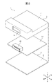
- FIG. 3 An exploded perspective view of the in-vehicle electronic device shown in FIG. 1.
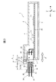
- FIG. 3 is a cross-sectional view of an in-vehicle electronic device and a wire harness shown in FIG.
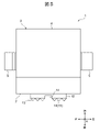
- the top view schematically shows the structure of the vehicle-mounted electronic device of Embodiment 2.
- FIG. 5 is a sectional view schematically showing a configuration of an in-vehicle electronic device according to a third embodiment.
- FIG. 7 is a perspective view of an in-vehicle electronic device and a wire harness shown in FIG. 7.
- the top view schematically shows the structure of the vehicle-mounted electronic device of Embodiment 4.
- FIG. 1 is a perspective view schematically showing the configuration of the in-vehicle electronic device 1 and the wire harness 30 of the first embodiment.
- FIG. 2 is an exploded perspective view of the in-vehicle electronic device 1 shown in FIG.
- FIG. 3 is a cross-sectional view of the in-vehicle electronic device 1 and the wire harness 30 shown in FIG.
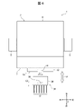
- FIG. 4 is a top view of the in-vehicle electronic device 1 and the wire harness 30 shown in FIG.
- the metal bracket 5 and the protrusion 12 shown in FIG. 1 are not shown, and the electronic component 21 shown in FIG. 3 is not shown.
- FIG. 3 is a cross-sectional view of the in-vehicle electronic device 1 and the wire harness 30 shown in FIG. 1 cut by a plane including the front-rear direction and the up-down direction.
- the in-vehicle electronic device 1 is an in-vehicle electronic device to which the wire harness 30 is connected.
- the in-vehicle electronic device 1 includes a metal housing 2 constituting the outer shell of the in-vehicle electronic device 1 and a circuit board 20 housed in the metal housing 2 (see FIG. 2).
- the circuit board 20 mounts a plurality of electronic components 21 such as semiconductor elements or capacitors, and also mounts a resin connector 22 that fits into the harness connector 32 of the wire harness 30 (see FIG. 3).
- the resin connector 22 of the in-vehicle electronic device 1 will be described as a male connector
- the harness connector 32 of the wire harness 30 will be described as a female connector
- the resin connector 22 may be a female connector
- the harness connector 32 may be a male connector.
- the resin connector 22 has a terminal 23 that conforms to standards for various uses such as for external communication or power supply, and a resin housing 24 that covers and holds the terminal 23. As shown in FIG. 3, one end of the terminal 23 is exposed from the housing 24 and is arranged so as to face the outside of the metal housing 2. The other end of the terminal 23 is joined to the circuit board 20 by solder or the like. That is, the resin connector 22 is mounted on the circuit board 20 facing the front portion 7 of the metal housing 2 described later inside the metal housing 2, and the harness connector 32 is inserted and removed.
- the wire harness 30 includes a wire 31 conforming to the standard of the terminal 23 in the resin connector 22 and a harness connector 32 provided at the end of the wire 31.
- the harness connector 32 has a terminal 33 corresponding to the terminal 23 in the resin connector 22, and a resin housing 34 that covers and holds the terminal 33.
- one end of the terminal 33 is connected to the wire 31.
- the other end of the terminal 33 is formed on the same plane as the surface of the housing 34 opposite to the surface through which the wire 31 penetrates.
- a claw-shaped latch portion 36 which is a retaining mechanism for the resin connector 22, is provided on one of the surfaces of the housing 34 other than the surface on which the wire 31 and the terminal 33 are provided.
- the latch portion 36 is provided on the upper surface portion 35 of the housing 34.
- the latch portion 36 is a portion that the operator's finger comes into contact with when the harness connector 32 is inserted or removed.
- the metal housing 2 includes a plate-shaped metal base 3 that constitutes the bottom surface of the metal housing 2 and a box-shaped metal cover 4 that covers the metal base 3.
- the metal housing 2 is connected to the frame ground of the vehicle via a metal bracket 5 attached to the side surface portions 9 and 10 described later of the metal cover 4.
- the metal cover 4 has a plate-shaped upper surface portion 6 arranged to face the metal base 3. Further, the metal cover 4 has a plate-shaped front portion 7 connected to the upper surface portion 6 and to which the wire harness 30 is connected, and a plate-shaped back surface portion 8 connected to the upper surface portion 6 and arranged to face the front surface portion 7. Have. Further, the metal cover 4 has plate-shaped side surface portions 9 and 10 which are connected to each of the upper surface portion 6, the front surface portion 7 and the back surface portion 8 and are arranged to face each other.
- the front portion 7 has an opening 11 formed at a position facing the resin connector 22.
- the opening 11 is a through hole formed for inserting the harness connector 32 into the resin connector 22.
- the opening 11 exposes the resin connector 22 arranged inside the metal housing 2 to the outside of the metal housing 2. That is, the front portion 7 is a portion constituting the connection surface to which the wire harness 30 is connected in the metal housing 2.
- the front portion 7 has a plate-shaped protruding portion 12 projecting to the outside of the metal housing 2 along the insertion / removal direction P of the harness connector 32.
- the insertion / removal direction P is the direction in which the harness connector 32 moves when the harness connector 32 is inserted into the resin connector 22 or the harness connector 32 is pulled out from the resin connector 22.
- the insertion / removal direction P corresponds to the front-rear direction shown in FIG.
- the protrusion 12 has a portion of the front portion 7 located between one side of the front portion 7 corresponding to the surface of the harness connector 32 provided with the latch portion 36 and the peripheral edge of the opening 11 as a base end, and the insertion / removal direction P. It is provided so as to project to the outside of the metal housing 2 along the above. In FIG.
- the projecting portion 12 is provided so as to project with a portion of the front surface portion 7 located between the peripheral edge of the opening portion 11 and the upper side of the front surface portion 7 as a base end.
- the portion of the front portion 7 above the peripheral edge of the opening 11 is a portion that is easily accessible by the operator's finger when the harness connector 32 is inserted or removed.
- the protrusion 12 may be integrally formed with the front portion 7 (metal cover 4), or may be formed separately from the front portion 7 (metal cover 4) and then joined to the front portion 7 (metal cover 4). You may.
- the protrusion 12 may form a canopy with respect to the opening 11.
- the tip portion 13 of the protruding portion 12 has a notch portion 14 formed in a shape corresponding to the latch portion 36 of the harness connector 32.
- the cutout portion 14 is formed in a shape that does not interfere with the latch portion 36 and the fingertips of the operator when the harness connector 32 is inserted into the resin connector 22.
- the left-right dimension of the latch portion 36 is L1 and the front-back dimension is L2
- the left-right dimension of the notch portion 14 is larger than L1 and the notch portion 14 is in the front-rear direction.
- the dimension of may be larger than L2.
- the tip portion 13 of the protruding portion 12 constitutes the farthest portion 15 which is the portion farthest from the terminal 23 in the resin connector 22 in the insertion / removal direction P of the harness connector 32. That is, the front portion 7 having the protruding portion 12 has the farthest portion 15.
- the farthest portion 15 is for in-vehicle use in which the harness connector 32 or the operator's fingertip first approaches. It is a part of the electronic device 1.
- the space insulation distance between the terminal 23 in the resin connector 22 and the terminal 33 in the harness connector 32 in the insertion / removal direction P is defined as A.
- B be the distance between the terminal 33 in the harness connector 32 and the metal housing 2.
- C be the distance between the latch portion 36 of the harness connector 32 and the metal housing 2.
- D be the distance between the terminal 23 in the resin connector 22 and the farthest portion 15 in the insertion / removal direction P.
- the distance D between the terminal 23 in the resin connector 22 and the farthest portion 15 in the insertion / removal direction P is the insertion / removal of the terminal 23 in the resin connector 22 and the terminal 33 in the harness connector 32. It is configured to be longer than the spatial insulation distance A in the direction P.
- the spatial insulation distance A is determined in advance based on the dielectric strength of air (3.0 MV / m), the operating voltage of the in-vehicle electronic device 1, the usage environment, and the like.
- the distance D between the terminal 23 in the resin connector 22 and the farthest portion 15 in the insertion / removal direction P is the distance in the insertion / removal direction P between the terminal 23 in the resin connector 22 and the tip portion 13 of the protrusion 12. Equivalent to.
- the wire harness 30 or the operator may be charged with static electricity in the installation work of the in-vehicle electronic device 1 or the maintenance and inspection work of the vehicle.
- this static electricity may be discharged to the vehicle-mounted electronic device 1 according to the following two patterns. That is, a pattern in which static electricity charged in the wire harness 30 is discharged from the terminal 33 of the harness connector 32 to the in-vehicle electronic device 1 (hereinafter, also referred to as “discharge pattern A”), and static electricity charged in the worker is the fingertip of the worker.
- discharge pattern B a pattern in which static electricity charged in the wire harness 30 is discharged from the terminal 33 of the harness connector 32 to the in-vehicle electronic device 1
- discharge pattern B There is a pattern (hereinafter, also referred to as “discharge pattern B”) of discharging to the in-vehicle electronic device 1.
- the portion of the vehicle-mounted electronic device 1 to which the harness connector 32 or the operator's fingertip first approaches when the wire harness 30 is connected is the farthest portion 15, and in the first embodiment, it protrudes.
- the distance D between the terminal 23 in the resin connector 22 and the farthest portion 15 in the insertion / removal direction P is longer than the spatial insulation distance A.
- the distance B between the terminal 33 in the harness connector 32 and the metal housing 2 is set between the terminal 33 in the harness connector 32 and the protruding portion 12. It becomes a distance and becomes shorter than the space insulation distance A.
- the distance C between the latch portion 36 of the harness connector 32 and the metal housing 2 is the distance between the latch portion 36 and the protruding portion 12, which is shorter than the spatial insulation distance A.
- the discharge destination of the static electricity discharged from the fingertip of the operator is not the terminal 23 in the resin connector 22 but the protruding portion 12 (tip portion 13). That is, in the in-vehicle electronic device 1, in any of the discharge patterns A and B, the discharge destination of static electricity can be the tip portion 13 of the protruding portion 12, which is the farthest portion 15.
- the static electricity that has reached the farthest portion 15 passes through the side surface portions 9 and 10 of the metal housing 2 and the metal bracket 5, and is released to the frame ground of the vehicle.
- the distance D in the insertion / removal direction P between the terminal 23 in the resin connector 22 and the farthest portion 15 is only made longer than the spatial insulation distance A, and the farthest portion is provided.
- the function of a lightning rod can be added to 15 as a discharge destination of static electricity, and electrostatic discharge to the circuit board 20 can be prevented. Therefore, in the in-vehicle electronic device 1 of the first embodiment, it is possible to easily prevent static electricity from being discharged to the circuit board 20 when the wire harness 30 is connected, and it is possible to prevent a failure or malfunction. be able to.
- the farthest portion 15 is composed of a tip portion 13 of a protruding portion 12 projecting to the outside of the metal housing 2 along the insertion / removal direction P of the harness connector 32. That is, in the in-vehicle electronic device 1 of the first embodiment, the insertion / removal direction of the terminal 23 and the farthest portion 15 in the resin connector 22 is simply provided by providing the protruding portion 12 with respect to the front portion 7 of the existing metal housing 2.
- the distance D in P can be made longer than the spatial insulation distance A.
- the vehicle-mounted electronic device 1 of the first embodiment can add the function of a lightning rod as a discharge destination of static electricity to the tip portion 13 of the protrusion 12 which is the farthest portion 15, and prevents static electricity discharge to the circuit board 20. be able to. Therefore, in the in-vehicle electronic device 1 of the first embodiment, it is possible to more easily prevent static electricity from being discharged to the circuit board 20 when the wire harness 30 is connected, and to prevent failure or malfunction. can do.
- the tip portion 13 of the protruding portion 12 has a notch portion 14 formed in a shape corresponding to the latch portion 36 of the harness connector 32, the harness connector 32 is inserted and removed. Occasionally, it is possible to prevent the latch portion 36 and the fingertips of the operator from interfering with the protruding portion 12.
- the vehicle-mounted electronic device 1 of the first embodiment can improve the workability at the time of inserting and removing the harness connector 32 only by providing the notch portion 14. Therefore, in the in-vehicle electronic device 1 of the first embodiment, it is possible to more easily prevent static electricity from being discharged to the circuit board 20 when the wire harness 30 is connected, and to prevent failure or malfunction. can do.
- the in-vehicle electronic device 1 of the first embodiment since the metal housing 2 is connected to the frame ground of the vehicle, the static electricity discharged to the protrusion 12 can be reliably discharged to the frame ground. As a result, the vehicle-mounted electronic device 1 of the first embodiment can lower the potential of the tip portion 13 of the protruding portion 12 which is the farthest portion 15, and can improve the function of the lightning rod as the discharge destination of static electricity. , It is possible to further prevent electrostatic discharge to the circuit board 20. Therefore, in the in-vehicle electronic device 1 of the first embodiment, it is possible to reliably prevent static electricity from being discharged to the circuit board 20 when the wire harness 30 is connected, and to prevent failure or malfunction. be able to.
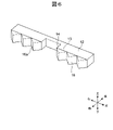
- FIG. 5 is a top view schematically showing the configuration of the in-vehicle electronic device 1 of the second embodiment.
- FIG. 6 is an enlarged perspective view of the protrusion 12 shown in FIG.
- the in-vehicle electronic device 1 of the second embodiment is different from the first embodiment in that the tip portion 13 of the protruding portion 12 has a pointed head portion 16 that is pointed toward the outside of the metal housing 2.
- the pointed head 16 is provided on an end face (front end face) intersecting the insertion / removal direction P of the tip portion 13.
- the pointed head 16 may be formed in a triangular prism shape so as to be sharpened in the direction (forward) of pulling out the harness connector 32, for example.
- the tip 16a of the pointed head 16 is chamfered and formed to be rounded.
- the farthest portion 15 is configured by the pointed head 16.
- the vehicle-mounted electronic device 1 of the second embodiment can generate an electric field concentration at the pointed head 16, so that the static electricity discharged from the harness connector 32 or the fingertip of the operator is generated at the farthest portion 15. It becomes easier to reach the tip portion 13 of a certain protruding portion 12.
- the vehicle-mounted electronic device 1 of the second embodiment can improve the function of the lightning rod possessed by the tip portion 13 of the protruding portion 12 which is the farthest portion 15 as compared with the first embodiment, and causes electrostatic discharge to the circuit board 20. It can be further prevented. Therefore, in the in-vehicle electronic device 1 of the second embodiment, static electricity can be more reliably prevented from being discharged to the circuit board 20 when the wire harness 30 is connected, and a failure or failure can occur. The malfunction can be prevented more reliably than in the first embodiment.
- FIG. 7 is a cross-sectional view schematically showing the configuration of the in-vehicle electronic device 1 of the third embodiment.
- FIG. 8 is a perspective view of the in-vehicle electronic device 1 and the wire harness 30 shown in FIG. 7. Note that FIG. 7 is a diagram corresponding to FIG.
- the in-vehicle electronic device 1 of the third embodiment is different from the first embodiment in that it does not have the protruding portion 12 and the arrangement of the front portion 7 is changed.
- the front portion 7 of the third embodiment is arranged at a distance longer than the spatial insulation distance A from the terminal 23 in the resin connector 22 in the insertion / removal direction P.
- the arrangement of the front portion 7 may be realized by moving the mounting position of the resin connector 22 on the circuit board 20 in the direction (rear) in which the harness connector 32 is inserted.
- the arrangement of the front portion 7 may be realized by extending the dimension of the metal housing 2 in the direction (forward) in which the harness connector 32 is pulled out.
- the farthest portion 15 is composed of the outer surface 7a of the front portion 7.
- the outer surface 7a of the front surface portion 7 is a surface opposite to the surface of the front surface portion 7 facing the resin connector 22.
- the spatial insulation distance between the terminal 23 in the resin connector 22 and the terminal 33 in the harness connector 32 in the insertion / removal direction P is defined as A.
- the distance between the terminal 33 in the harness connector 32 and the metal housing 2 is defined as B'.
- the distance between the latch portion 36 of the harness connector 32 and the metal housing 2 is defined as C'.
- D be the distance between the terminal 23 in the resin connector 22 and the farthest portion 15 in the insertion / removal direction P.
- the distance D in the insertion / removal direction P between the terminal 23 in the resin connector 22 and the farthest portion 15 is configured to be longer than the spatial insulation distance A.
- the distance D between the terminal 23 in the resin connector 22 and the farthest portion 15 in the insertion / removal direction P is the distance in the insertion / removal direction P between the terminal 23 in the resin connector 22 and the outer surface 7a of the front surface portion 7. Equivalent to.
- the distance B'between the terminal 33 in the harness connector 32 and the metal housing 2 is the terminal 33 in the harness connector 32 and the front portion 7. It becomes a distance from and becomes shorter than the space insulation distance A.
- the distance C'between the latch portion 36 of the harness connector 32 and the metal housing 2 is the distance between the latch portion 36 and the front surface portion 7, which is shorter than the spatial insulation distance A.
- the vehicle-mounted electronic device 1 of the third embodiment sets the distance D between the terminal 23 in the resin connector 22 and the farthest portion 15 in the insertion / removal direction P from the spatial insulation distance A without providing the protruding portion 12. Can also be lengthened.
- the function of a lightning rod can be added to the outer surface 7a of the front surface portion 7, which is the farthest portion 15, as a discharge destination of static electricity, further simplifying the electrostatic discharge to the circuit board 20. Can be prevented. Therefore, in the in-vehicle electronic device 1 of the third embodiment, it is possible to prevent static electricity from being discharged to the circuit board 20 when the wire harness 30 is connected, as compared with the first embodiment. The malfunction can be prevented more easily than in the first embodiment.
- the front surface portion 7 and the upper surface portion 6 have a notch portion 14 formed in a shape corresponding to the latch portion 36 of the harness connector 32. ..
- the in-vehicle electronic device 1 of the third embodiment can prevent the latch portion 36 and the fingertips of the operator from interfering with the front portion 7 and the upper surface portion 6 when the harness connector 32 is inserted and removed. Therefore, the in-vehicle electronic device 1 of the third embodiment can improve the workability at the time of inserting and removing the harness connector 32 as in the first embodiment.
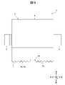
- FIG. 9 is a top view schematically showing the configuration of the in-vehicle electronic device 1 of the fourth embodiment.
- the in-vehicle electronic device 1 of the fourth embodiment is different from the third embodiment in that the outer surface 7a of the front surface portion 7 has a pointed head 16 pointed toward the outside of the metal housing 2.
- the pointed head 16 of the fourth embodiment may be provided at the same position as the position where the protruding portion 12 of the second embodiment is provided. Similar to the pointed head 16 of the second embodiment, the pointed head 16 of the fourth embodiment may be formed in a triangular prism shape so as to be sharpened toward the pulling direction (forward) of the harness connector 32, for example.
- the tip 16a of the pointed head 16 of the fourth embodiment may be chamfered and rounded.
- the farthest portion 15 is configured by the pointed head 16.
- the vehicle-mounted electronic device 1 of the fourth embodiment can generate an electric field concentration at the tip 16 as in the second embodiment, so that the static electricity discharged from the harness connector 32 or the fingertip of the operator is discharged. However, it becomes easier to reach the outer surface 7a of the front surface portion 7, which is the farthest portion 15.
- the vehicle-mounted electronic device 1 of the fourth embodiment can improve the function of the lightning rod on the outer surface 7a of the front surface portion 7, which is the farthest portion 15, as compared with the third embodiment, and causes electrostatic discharge to the circuit board 20. It can be further prevented.
- the present invention is not limited to the above embodiment, and includes various modifications.
- the above-described embodiment has been described in detail in order to explain the present invention in an easy-to-understand manner, and is not necessarily limited to the one including all the described configurations.
- it is possible to replace a part of the configuration of one embodiment with the configuration of another embodiment and it is also possible to add the configuration of another embodiment to the configuration of one embodiment.
- each of the above configurations, functions, processing units, processing means, etc. may be realized by hardware by designing a part or all of them by, for example, an integrated circuit. Further, each of the above configurations, functions, and the like may be realized by software by the processor interpreting and executing a program that realizes each function. Information such as programs, tapes, and files that realize each function can be placed in a memory, a recording device such as a hard disk or SSD (solid state drive), or a recording medium such as an IC card, SD card, or DVD.
- a recording device such as a hard disk or SSD (solid state drive)
- a recording medium such as an IC card, SD card, or DVD.
- control lines and information lines indicate those that are considered necessary for explanation, and do not necessarily indicate all control lines and information lines in the product. In practice, it can be considered that almost all configurations are interconnected.
Landscapes
- Engineering & Computer Science (AREA)
- Microelectronics & Electronic Packaging (AREA)
- Architecture (AREA)
- Civil Engineering (AREA)
- Structural Engineering (AREA)
- Mechanical Engineering (AREA)
- Details Of Connecting Devices For Male And Female Coupling (AREA)
- Elimination Of Static Electricity (AREA)
- Casings For Electric Apparatus (AREA)
- Connection Or Junction Boxes (AREA)
Abstract
ワイヤハーネスが接続される際に回路基板に対して静電気が放電されることを簡易に防止することが可能な車載用電子装置を提供する。車載用電子装置1は、ワイヤハーネス30が接続される車載用電子装置である。車載用電子装置1は、内部に回路基板20を収容し、ワイヤハーネス30が接続される正面部7を有する金属筐体2と、金属筐体2の内部において正面部7に対向して回路基板20に搭載され、ワイヤハーネス30のハーネスコネクタ32が挿抜される樹脂コネクタ22と、を備える。正面部7は、ハーネスコネクタ32の挿抜方向Pにおいて樹脂コネクタ22内の端子23から最も離れた部分である最遠部15を有する。樹脂コネクタ22内の端子23と最遠部15との挿抜方向Pにおける距離Dは、樹脂コネクタ22内の端子23とハーネスコネクタ32内の端子33との挿抜方向Pにおける空間絶縁距離Aよりも長い。
Description
本発明は、車載用電子装置に関する。
車載用電子装置は、電子化が進み、外部との通信が多くなってきている。車載用電子装置では、金属筐体に回路基板を収容し、当該回路基板に外部との通信用のコネクタが搭載されている。車載用電子装置のコネクタに接続されるワイヤハーネス又は作業者には、車載用電子装置の梱包若しくは取り付け作業又は車両の保守点検作業等において、静電気が帯電することがある。車載用電子装置のコネクタにワイヤハーネスを接続する際、ワイヤハーネス又は作業者に帯電している静電気が回路基板に放電することによって、車載用電子装置が故障したり誤作動を起こしたりする可能性がある。よって、車載用電子装置には、回路基板への静電気放電を防止する対策が求められる。
特許文献1に記載の車両電子制御ユニット用ケースは、電子制御ユニットを内部に収容し、下方及び一側方に開口を有するケース本体と、ケース本体の下方の開口を閉塞するカバーと、を備え、一側方の開口に電子制御ユニットのコネクタが収まって車両に搭載される車両電子制御ユニット用ケースであって、ケース本体のうち一側方の開口の上方に位置する上方部位から一側方に突出し、コネクタの被水を抑制する防水ひさしを備える。
特許文献1に記載の車両電子制御ユニット用ケースは、ワイヤハーネスを接続する際、ケース本体の上方部位と防水ひさしとの接合部分を軸として、防水ひさしをケース上方に回動する必要がある。よって、特許文献1に記載の防水ひさしは、静電気の放電先として避雷針のような機能を有することができない。
本発明は、上記に鑑みてなされたものであり、ワイヤハーネスが接続される際に回路基板に対して静電気が放電されることを簡易に防止することが可能な車載用電子装置を提供することを目的とする。
上記課題を解決するために、本発明に係る車載用電子装置は、ワイヤハーネスが接続される車載用電子装置であって、内部に回路基板を収容し、前記ワイヤハーネスが接続される正面部を有する金属筐体と、前記金属筐体の前記内部において前記正面部に対向して前記回路基板に搭載され、前記ワイヤハーネスのハーネスコネクタが挿抜される樹脂コネクタと、を備え、前記正面部は、前記ハーネスコネクタの挿抜方向において前記樹脂コネクタ内の端子から最も離れた部分である最遠部を有し、前記樹脂コネクタ内の前記端子と前記最遠部との前記挿抜方向における距離が、前記樹脂コネクタ内の前記端子と前記ハーネスコネクタ内の端子との前記挿抜方向における空間絶縁距離よりも長いことを特徴とする。
本発明によれば、ワイヤハーネスが接続される際に回路基板に対して静電気が放電されることを簡易に防止することが可能な車載用電子装置を提供することができる。
上記以外の課題、構成および効果は、以下の実施形態の説明により明らかにされる。
上記以外の課題、構成および効果は、以下の実施形態の説明により明らかにされる。
以下、本発明の実施形態について図面を用いて説明する。なお、各実施形態において同一の符号を付された構成は、特に言及しない限り、各実施形態において同様の機能を有し、その説明を省略する。
[実施形態1]
図1は、実施形態1の車載用電子装置1及びワイヤハーネス30の構成を模式的に示す斜視図である。図2は、図1に示す車載用電子装置1の分解斜視図である。図3は、図1に示す車載用電子装置1及びワイヤハーネス30の断面図である。図4は、図1に示す車載用電子装置1及びワイヤハーネス30の上面図である。なお、図2では、図1に示す金属ブラケット5及び突出部12の図示が省略されていると共に、図3に示す電子部品21の図示が省略されている。図3は、図1に示す車載用電子装置1及びワイヤハーネス30を、前後方向及び上下方向を含む平面によって切断した断面図である。
図1は、実施形態1の車載用電子装置1及びワイヤハーネス30の構成を模式的に示す斜視図である。図2は、図1に示す車載用電子装置1の分解斜視図である。図3は、図1に示す車載用電子装置1及びワイヤハーネス30の断面図である。図4は、図1に示す車載用電子装置1及びワイヤハーネス30の上面図である。なお、図2では、図1に示す金属ブラケット5及び突出部12の図示が省略されていると共に、図3に示す電子部品21の図示が省略されている。図3は、図1に示す車載用電子装置1及びワイヤハーネス30を、前後方向及び上下方向を含む平面によって切断した断面図である。
車載用電子装置1は、ワイヤハーネス30が接続される車載用電子装置である。車載用電子装置1は、車載用電子装置1の外郭を構成する金属筐体2と、金属筐体2に収容される回路基板20とを備える(図2を参照)。
回路基板20は、半導体素子又はコンデンサ等の複数の電子部品21を搭載すると共に、ワイヤハーネス30のハーネスコネクタ32に嵌合する樹脂コネクタ22を搭載する(図3を参照)。実施形態1では、車載用電子装置1の樹脂コネクタ22をオス型コネクタとし、ワイヤハーネス30のハーネスコネクタ32をメス型コネクタとして説明する。樹脂コネクタ22はメス型コネクタであり、ハーネスコネクタ32はオス型コネクタであってもよい。
樹脂コネクタ22は、外部通信用又は電力供給用等の各種用途の規格に適合する端子23と、端子23を覆って保持する樹脂製のハウジング24とを有する。図3に示すように、端子23の一端は、ハウジング24から露出し、金属筐体2の外部を向くように配置される。端子23の他端は、回路基板20にはんだ等によって接合されている。すなわち、樹脂コネクタ22は、金属筐体2の内部において後述する金属筐体2の正面部7に対向して回路基板20に搭載され、ハーネスコネクタ32が挿抜される。
ワイヤハーネス30は、樹脂コネクタ22内の端子23の規格に適合するワイヤ31と、ワイヤ31の端部に設けられたハーネスコネクタ32とを備える。ハーネスコネクタ32は、樹脂コネクタ22内の端子23に対応する端子33と、端子33を覆って保持する樹脂製のハウジング34とを有する。図3に示すように、端子33の一端は、ワイヤ31に接続される。端子33の他端は、ハウジング34のワイヤ31が貫通する面とは反対側の面と、同一平面上に形成される。ハウジング34の、ワイヤ31及び端子33が設けられた面以外の面の1つには、樹脂コネクタ22に対する抜け止め機構である爪状のラッチ部36が設けられる。図1では、ラッチ部36は、ハウジング34の上面部35に設けられる。ラッチ部36は、ハーネスコネクタ32の挿抜時に作業者の指が接触する部分である。
金属筐体2は、金属筐体2の底面部を構成する板状の金属ベース3と、金属ベース3を覆う箱状の金属カバー4とを備える。金属筐体2は、金属カバー4の後述する側面部9,10に取り付けられた金属ブラケット5を介して、車両のフレームグラウンドに接続される。
金属カバー4は、図1に示すように、金属ベース3に対向配置される板状の上面部6を有する。更に、金属カバー4は、上面部6に連接しワイヤハーネス30が接続される板状の正面部7と、上面部6に連接し正面部7に対向配置される板状の背面部8とを有する。更に、金属カバー4は、上面部6、正面部7及び背面部8のそれぞれに連接し互いに対向配置される板状の側面部9,10を有する。
正面部7は、樹脂コネクタ22と対向する位置に形成された開口部11を有する。開口部11は、ハーネスコネクタ32を樹脂コネクタ22に挿し込むために形成された貫通孔である。開口部11は、金属筐体2の内部に配置された樹脂コネクタ22を金属筐体2の外部に露出させる。すなわち、正面部7は、金属筐体2においてワイヤハーネス30が接続される接続面を構成する部分である。
正面部7は、ハーネスコネクタ32の挿抜方向Pに沿って金属筐体2の外部に突出する板状の突出部12を有する。挿抜方向Pとは、ハーネスコネクタ32を樹脂コネクタ22に挿し込んだり、ハーネスコネクタ32を樹脂コネクタ22から引き抜いたりする際に、ハーネスコネクタ32が移動する方向である。挿抜方向Pは、図1に示す前後方向に対応する。突出部12は、ハーネスコネクタ32のラッチ部36が設けられた面に対応する正面部7の一辺と開口部11の周縁との間に位置する正面部7の部分を基端として、挿抜方向Pに沿って金属筐体2の外部に突出するように設けられる。図1では、突出部12は、開口部11の周縁と正面部7の上側の一辺との間に位置する正面部7の部分を基端として突出するように設けられる。開口部11の周縁より上側の正面部7の部分は、ハーネスコネクタ32の挿抜時に作業者の指が接近し易い部分である。突出部12は、正面部7(金属カバー4)と一体的に形成されてもよいし、正面部7(金属カバー4)と別個に形成された後に正面部7(金属カバー4)に接合されてもよい。突出部12は、開口部11に対するひさしを構成してもよい。
突出部12の先端部13には、ハーネスコネクタ32のラッチ部36に対応する形状に形成された切り欠き部14を有する。切り欠き部14は、ハーネスコネクタ32が樹脂コネクタ22に挿し込まれた状態において、ラッチ部36及び作業者の指先と干渉しない形状に形成される。図4に示すように、ラッチ部36の左右方向の寸法がL1であり前後方向の寸法がL2である場合、切り欠き部14の左右方向の寸法はL1より大きく、切り欠き部14の前後方向の寸法はL2より大きくてもよい。
突出部12の先端部13は、ハーネスコネクタ32の挿抜方向Pにおいて樹脂コネクタ22内の端子23から最も離れた部分である最遠部15を構成する。すなわち、突出部12を有する正面部7は、最遠部15を有する。ワイヤハーネス30が車載用電子装置1に接続される際(ハーネスコネクタ32が樹脂コネクタ22に挿し込まれる際)、最遠部15は、ハーネスコネクタ32又は作業者の指先が最初に接近する車載用電子装置1の部分である。
ここで、図3に示すように、樹脂コネクタ22内の端子23とハーネスコネクタ32内の端子33との挿抜方向Pにおける空間絶縁距離を、Aとする。ハーネスコネクタ32内の端子33と金属筐体2との距離を、Bとする。ハーネスコネクタ32のラッチ部36と金属筐体2との距離を、Cとする。樹脂コネクタ22内の端子23と最遠部15との挿抜方向Pにおける距離を、Dとする。
このとき、車載用電子装置1では、樹脂コネクタ22内の端子23と最遠部15との挿抜方向Pにおける距離Dが、樹脂コネクタ22内の端子23とハーネスコネクタ32内の端子33との挿抜方向Pにおける空間絶縁距離Aよりも長くなるように構成される。この空間絶縁距離Aは、空気の絶縁耐力(3.0MV/m)と、車載用電子装置1の動作電圧及び使用環境等に基づいて予め決定される。樹脂コネクタ22内の端子23と最遠部15との挿抜方向Pにおける距離Dは、実施形態1では、樹脂コネクタ22内の端子23と突出部12の先端部13との挿抜方向Pにおける距離に相当する。
上記のように、車載用電子装置1の取り付け作業又は車両の保守点検作業等において、ワイヤハーネス30又は作業者には静電気が帯電することがある。ワイヤハーネス30が車載用電子装置1に接続される際、この静電気は、次の2通りのパターンによって車載用電子装置1に放電する可能性がある。すなわち、ワイヤハーネス30に帯電した静電気が、ハーネスコネクタ32の端子33から車載用電子装置1に放電するパターン(以下「放電パターンA」とも称する)と、作業者に帯電した静電気が作業者の指先から車載用電子装置1に放電するパターン(以下「放電パターンB」とも称する)とがある。
車載用電子装置1において、ワイヤハーネス30が接続される際にハーネスコネクタ32又は作業者の指先が最初に接近する車載用電子装置1の部分は、最遠部15であり、実施形態1では突出部12の先端部13である。車載用電子装置1は、樹脂コネクタ22内の端子23と最遠部15との挿抜方向Pにおける距離Dが、空間絶縁距離Aよりも長い。これにより、車載用電子装置1では、ワイヤハーネス30が接続される際、ハーネスコネクタ32内の端子33と金属筐体2との距離Bは、ハーネスコネクタ32内の端子33と突出部12との距離となり、空間絶縁距離Aよりも短くなる。同様に、ハーネスコネクタ32のラッチ部36と金属筐体2との距離Cは、ラッチ部36と突出部12との距離となり、空間絶縁距離Aよりも短くなる。そして、ワイヤハーネス30が接続される際、ハーネスコネクタ32内の端子33は、樹脂コネクタ22内の端子23よりも早く突出部12に接近し、作業者の指先は、樹脂コネクタ22内の端子23よりも早く突出部12に接近する。したがって、車載用電子装置1では、放電パターンAにおいて、ハーネスコネクタ32の端子33から放電した静電気が最初に到達する車載用電子装置1の部分(以下「放電先」とも称する)は、樹脂コネクタ22内の端子23ではなく、突出部12(の先端部13)となる。更に、車載用電子装置1では、放電パターンBにおいて、作業者の指先から放電した静電気の放電先についても、樹脂コネクタ22内の端子23ではなく、突出部12(の先端部13)となる。すなわち、車載用電子装置1では、放電パターンA及びBの何れにおいても、静電気の放電先を、最遠部15である突出部12の先端部13とすることができる。最遠部15に到達した静電気は、金属筐体2の側面部9,10及び金属ブラケット5を通過して、車両のフレームグラウンドに放出される。
このように、実施形態1の車載用電子装置1では、樹脂コネクタ22内の端子23と最遠部15との挿抜方向Pにおける距離Dを空間絶縁距離Aよりも長くするだけで、最遠部15に静電気の放電先として避雷針の機能を付加することができ、回路基板20への静電気放電を防止することができる。よって、実施形態1の車載用電子装置1では、ワイヤハーネス30が接続される際に回路基板20に対して静電気が放電されることを簡易に防止することができ、故障又は誤作動を防止することができる。
特に、実施形態1の車載用電子装置1では、最遠部15が、ハーネスコネクタ32の挿抜方向Pに沿って金属筐体2の外部に突出する突出部12の先端部13によって構成される。すなわち、実施形態1の車載用電子装置1では、既存の金属筐体2の正面部7に対して突出部12を設けるだけで、樹脂コネクタ22内の端子23と最遠部15との挿抜方向Pにおける距離Dを空間絶縁距離Aよりも長くすることができる。実施形態1の車載用電子装置1は、最遠部15である突出部12の先端部13に静電気の放電先として避雷針の機能を付加することができ、回路基板20への静電気放電を防止することができる。よって、実施形態1の車載用電子装置1では、ワイヤハーネス30が接続される際に回路基板20に対して静電気が放電されることを更に簡易に防止することができ、故障又は誤作動を防止することができる。
更に、実施形態1の車載用電子装置1は、突出部12の先端部13は、ハーネスコネクタ32のラッチ部36に対応する形状に形成された切り欠き部14を有するので、ハーネスコネクタ32の挿抜時に、ラッチ部36及び作業者の指先が突出部12に干渉することを防止することができる。実施形態1の車載用電子装置1は、切り欠き部14を設けるだけで、ハーネスコネクタ32の挿抜時の作業性を向上させることができる。よって、実施形態1の車載用電子装置1では、ワイヤハーネス30が接続される際に回路基板20に対して静電気が放電されることを更に簡易に防止することができ、故障又は誤作動を防止することができる。
更に、実施形態1の車載用電子装置1は、金属筐体2が車両のフレームグラウンドに接続されているので、突出部12に放電された静電気をフレームグラウンドに確実に放出することができる。これにより、実施形態1の車載用電子装置1は、最遠部15である突出部12の先端部13の電位を下げることができ、静電気の放電先としての避雷針の機能を向上させることができ、回路基板20への静電気放電を更に防止することができる。よって、実施形態1の車載用電子装置1では、ワイヤハーネス30が接続される際に回路基板20に対して静電気が放電されることを確実に防止することができ、故障又は誤作動を防止することができる。
[他の実施形態]
図5~図9を用いて、実施形態2~4の車載用電子装置1について説明する。実施形態2~4の説明において、従前の実施形態と同様の構成及び動作の説明については省略する。
図5~図9を用いて、実施形態2~4の車載用電子装置1について説明する。実施形態2~4の説明において、従前の実施形態と同様の構成及び動作の説明については省略する。
図5は、実施形態2の車載用電子装置1の構成を模式的に示す上面図である。図6は、図5に示す突出部12の拡大斜視図である。
実施形態2の車載用電子装置1において、実施形態1と異なる点は、突出部12の先端部13が、金属筐体2の外部に向けて尖った尖頭部16を有する点である。尖頭部16は、先端部13の挿抜方向Pに交差する端面(前端面)に設けられる。尖頭部16は、図6に示すように、例えば、ハーネスコネクタ32を引き抜く方向(前方)に向かうに従って尖るような三角柱形状に形成されてもよい。尖頭部16の先端16aは、面取りされ、丸みを帯びて形成される。これにより、ハーネスコネクタ32の挿抜時に作業者の指先が尖頭部16に触れても切創等の怪我には至らず、安全性を確保することができる。実施形態2の車載用電子装置1では、最遠部15が尖頭部16によって構成される。
この構成により、実施形態2の車載用電子装置1は、尖頭部16において電界集中を発生させることができるので、ハーネスコネクタ32又は作業者の指先から放電された静電気が、最遠部15である突出部12の先端部13に到達し易くなる。実施形態2の車載用電子装置1は、最遠部15である突出部12の先端部13が有する避雷針の機能を、実施形態1よりも向上させることができ、回路基板20への静電気放電を更に防止することができる。よって、実施形態2の車載用電子装置1では、ワイヤハーネス30が接続される際に回路基板20に対して静電気が放電されることを実施形態1よりも確実に防止することができ、故障又は誤作動を実施形態1よりも確実に防止することができる。
図7は、実施形態3の車載用電子装置1の構成を模式的に示す断面図である。図8は、図7に示す車載用電子装置1及びワイヤハーネス30の斜視図である。なお、図7は、図3に対応する図である。
実施形態3の車載用電子装置1において、実施形態1と異なる点は、突出部12を有しておらず、正面部7の配置が変更されている点である。実施形態3の正面部7は、挿抜方向Pにおいて、樹脂コネクタ22内の端子23から空間絶縁距離Aよりも長い距離だけ離れて配置されている。この正面部7の配置は、回路基板20における樹脂コネクタ22の搭載位置を、ハーネスコネクタ32を挿し込む方向(後方)に移動させることによって実現されてもよい。或いは、この正面部7の配置は、金属筐体2の寸法を、ハーネスコネクタ32を引き抜く方向(前方)に伸ばすことによって実現されてもよい。実施形態3の車載用電子装置1では、最遠部15が正面部7の外表面7aによって構成される。正面部7の外表面7aは、正面部7の樹脂コネクタ22に対向する面とは反対側の面である。
ここで、図7に示すように、樹脂コネクタ22内の端子23とハーネスコネクタ32内の端子33との挿抜方向Pにおける空間絶縁距離を、Aとする。ハーネスコネクタ32内の端子33と金属筐体2との距離を、B’とする。ハーネスコネクタ32のラッチ部36と金属筐体2との距離を、C’とする。樹脂コネクタ22内の端子23と最遠部15との挿抜方向Pにおける距離を、Dとする。
このとき、実施形態3の車載用電子装置1では、樹脂コネクタ22内の端子23と最遠部15との挿抜方向Pにおける距離Dが、空間絶縁距離Aよりも長くなるように構成される。樹脂コネクタ22内の端子23と最遠部15との挿抜方向Pにおける距離Dは、実施形態3では、樹脂コネクタ22内の端子23と正面部7の外表面7aとの挿抜方向Pにおける距離に相当する。
実施形態3の車載用電子装置1では、ワイヤハーネス30が接続される際、ハーネスコネクタ32内の端子33と金属筐体2との距離B’は、ハーネスコネクタ32内の端子33と正面部7との距離となり、空間絶縁距離Aよりも短くなる。同様に、ハーネスコネクタ32のラッチ部36と金属筐体2との距離C’は、ラッチ部36と正面部7との距離となり、空間絶縁距離Aよりも短くなる。そして、ワイヤハーネス30が接続される際、ハーネスコネクタ32内の端子33は、樹脂コネクタ22内の端子23よりも早く正面部7に接近し、作業者の指先は、樹脂コネクタ22内の端子23よりも早く正面部7に接近する。したがって、実施形態3の車載用電子装置1では、ハーネスコネクタ32又は作業者の指先から放電された静電気の放電先が、最遠部15である正面部7(の外表面7a)となる。
この構成により、実施形態3の車載用電子装置1は、突出部12を設けなくても、樹脂コネクタ22内の端子23と最遠部15との挿抜方向Pにおける距離Dを空間絶縁距離Aよりも長くすることができる。実施形態3の車載用電子装置1は、最遠部15である正面部7の外表面7aに静電気の放電先として避雷針の機能を付加することができ、回路基板20への静電気放電を更に簡易に防止することができる。よって、実施形態3の車載用電子装置1では、ワイヤハーネス30が接続される際に回路基板20に対して静電気が放電されることを実施形態1よりも簡易に防止することができ、故障又は誤作動を実施形態1よりも簡易に防止することができる。
また、図8に示すように、実施形態3の車載用電子装置1は、正面部7及び上面部6は、ハーネスコネクタ32のラッチ部36に対応する形状に形成された切り欠き部14を有する。これにより、実施形態3の車載用電子装置1は、ハーネスコネクタ32の挿抜時に、ラッチ部36及び作業者の指先が正面部7及び上面部6に干渉することを防止することができる。よって、実施形態3の車載用電子装置1は、実施形態1と同様に、ハーネスコネクタ32の挿抜時の作業性を向上させることができる。
図9は、実施形態4の車載用電子装置1の構成を模式的に示す上面図である。
実施形態4の車載用電子装置1において、実施形態3と異なる点は、正面部7の外表面7aが、金属筐体2の外部に向けて尖った尖頭部16を有する点である。実施形態4の尖頭部16は、実施形態2の突出部12が設けられた位置と同様の位置に設けられてもよい。実施形態4の尖頭部16は、実施形態2の尖頭部16と同様に、例えば、ハーネスコネクタ32を引き抜く方向(前方)に向かうに従って尖るような三角柱形状に形成されてもよい。実施形態4の尖頭部16の先端16aは、面取りされ、丸みを帯びて形成されてもよい。実施形態4の車載用電子装置1では、最遠部15が尖頭部16によって構成される。
この構成により、実施形態4の車載用電子装置1は、実施形態2と同様に、尖頭部16において電界集中を発生させることができるので、ハーネスコネクタ32又は作業者の指先から放電された静電気が、最遠部15である正面部7の外表面7aに到達し易くなる。実施形態4の車載用電子装置1は、最遠部15である正面部7の外表面7aが有する避雷針の機能を、実施形態3よりも向上させることができ、回路基板20への静電気放電を更に防止することができる。よって、実施形態4の車載用電子装置1では、ワイヤハーネス30が接続される際に回路基板20に対して静電気が放電されることを実施形態3よりも確実に防止することができ、故障又は誤作動を実施形態3よりも確実に防止することができる。
[その他]
なお、本発明は上記の実施形態に限定されるものではなく、様々な変形例が含まれる。例えば、上記の実施形態は本発明を分かりやすく説明するために詳細に説明したものであり、必ずしも説明した全ての構成を備えるものに限定されるものではない。また、或る実施形態の構成の一部を他の実施形態の構成に置き換えることが可能であり、また、或る実施形態の構成に他の実施形態の構成を加えることも可能である。また、各実施形態の構成の一部について、他の構成の追加・削除・置換をすることが可能である。
なお、本発明は上記の実施形態に限定されるものではなく、様々な変形例が含まれる。例えば、上記の実施形態は本発明を分かりやすく説明するために詳細に説明したものであり、必ずしも説明した全ての構成を備えるものに限定されるものではない。また、或る実施形態の構成の一部を他の実施形態の構成に置き換えることが可能であり、また、或る実施形態の構成に他の実施形態の構成を加えることも可能である。また、各実施形態の構成の一部について、他の構成の追加・削除・置換をすることが可能である。
また、上記の各構成、機能、処理部、処理手段等は、それらの一部又は全部を、例えば集積回路にて設計する等によりハードウェアによって実現してもよい。また、上記の各構成、機能等は、プロセッサがそれぞれの機能を実現するプログラムを解釈し、実行することによりソフトウェアによって実現してもよい。各機能を実現するプログラム、テープ、ファイル等の情報は、メモリや、ハードディスク、SSD(solid state drive)等の記録装置、又は、ICカード、SDカード、DVD等の記録媒体に置くことができる。
また、制御線や情報線は説明上必要と考えられるものを示しており、製品上必ずしも全ての制御線や情報線を示しているとは限らない。実際には殆ど全ての構成が相互に接続されていると考えてもよい。
1…車載用電子装置、2…金属筐体、7…正面部、7a…外表面、12…突出部、13…先端部、14…切り欠き部、15…最遠部、16…尖頭部、20…回路基板、22…樹脂コネクタ、23…端子、30…ワイヤハーネス、32…ハーネスコネクタ、33…端子、36…ラッチ部
Claims (8)
- ワイヤハーネスが接続される車載用電子装置であって、
内部に回路基板を収容し、前記ワイヤハーネスが接続される正面部を有する金属筐体と、
前記金属筐体の前記内部において前記正面部に対向して前記回路基板に搭載され、前記ワイヤハーネスのハーネスコネクタが挿抜される樹脂コネクタと、を備え、
前記正面部は、前記ハーネスコネクタの挿抜方向において前記樹脂コネクタ内の端子から最も離れた部分である最遠部を有し、
前記樹脂コネクタ内の前記端子と前記最遠部との前記挿抜方向における距離が、前記樹脂コネクタ内の前記端子と前記ハーネスコネクタ内の端子との前記挿抜方向における空間絶縁距離よりも長い
ことを特徴とする車載用電子装置。 - 前記正面部は、前記挿抜方向に沿って前記金属筐体の外部に突出する突出部を有し、
前記最遠部は、前記突出部の先端部によって構成される
ことを特徴とする請求項1に記載の車載用電子装置。 - 前記ハーネスコネクタは、前記樹脂コネクタに対する抜け止め機構であるラッチ部を有し、
前記突出部の前記先端部は、前記ラッチ部に対応する形状に形成された切り欠き部を有する
ことを特徴とする請求項2に記載の車載用電子装置。 - 前記突出部の前記先端部は、前記金属筐体の前記外部に向けて尖った尖頭部を有する
ことを特徴とする請求項2に記載の車載用電子装置。 - 前記正面部は、前記挿抜方向において前記樹脂コネクタ内の前記端子から、前記空間絶縁距離よりも長い距離だけ離れて配置されており、
前記最遠部は、前記正面部の外表面によって構成される
ことを特徴とする請求項1に記載の車載用電子装置。 - 前記ハーネスコネクタは、前記樹脂コネクタに対する抜け止め機構であるラッチ部を有し、
前記正面部は、前記ラッチ部に対応する形状に形成された切り欠き部を有する
ことを特徴とする請求項5に記載の車載用電子装置。 - 前記正面部の前記外表面は、前記金属筐体の外部に向けて尖った尖頭部を有する
ことを特徴とする請求項5に記載の車載用電子装置。 - 前記金属筐体は、車両のフレームグラウンドに接続されている
ことを特徴とする請求項1に記載の車載用電子装置。
Applications Claiming Priority (2)
| Application Number | Priority Date | Filing Date | Title |
|---|---|---|---|
| JP2021001997A JP2024038526A (ja) | 2021-01-08 | 2021-01-08 | 車載用電子装置 |
| JP2021-001997 | 2021-01-08 |
Publications (1)
| Publication Number | Publication Date |
|---|---|
| WO2022149304A1 true WO2022149304A1 (ja) | 2022-07-14 |
Family
ID=82357853
Family Applications (1)
| Application Number | Title | Priority Date | Filing Date |
|---|---|---|---|
| PCT/JP2021/031925 Ceased WO2022149304A1 (ja) | 2021-01-08 | 2021-08-31 | 車載用電子装置 |
Country Status (2)
| Country | Link |
|---|---|
| JP (1) | JP2024038526A (ja) |
| WO (1) | WO2022149304A1 (ja) |
Citations (6)
| Publication number | Priority date | Publication date | Assignee | Title |
|---|---|---|---|---|
| JPS588882U (ja) * | 1981-07-10 | 1983-01-20 | エスエムケイ株式会社 | コネクタソケツト |
| JPH0620737A (ja) * | 1992-03-20 | 1994-01-28 | Whitaker Corp:The | 電気コネクタ |
| WO1999060464A1 (en) * | 1998-05-19 | 1999-11-25 | Sega Enterprises, Ltd. | Information processor, connection cable used therefor, connector, and plug |
| US6305986B1 (en) * | 2000-05-18 | 2001-10-23 | Hon Hai Precision Ind. Co., Ltd. | Cable connector assembly having improved grounding means |
| JP2005100906A (ja) * | 2003-08-18 | 2005-04-14 | Kyocera Mita Corp | コネクタ端子付電子装置及び画像形成装置 |
| JP2010114110A (ja) * | 2008-11-04 | 2010-05-20 | Canon Inc | 電子機器 |
-
2021
- 2021-01-08 JP JP2021001997A patent/JP2024038526A/ja active Pending
- 2021-08-31 WO PCT/JP2021/031925 patent/WO2022149304A1/ja not_active Ceased
Patent Citations (6)
| Publication number | Priority date | Publication date | Assignee | Title |
|---|---|---|---|---|
| JPS588882U (ja) * | 1981-07-10 | 1983-01-20 | エスエムケイ株式会社 | コネクタソケツト |
| JPH0620737A (ja) * | 1992-03-20 | 1994-01-28 | Whitaker Corp:The | 電気コネクタ |
| WO1999060464A1 (en) * | 1998-05-19 | 1999-11-25 | Sega Enterprises, Ltd. | Information processor, connection cable used therefor, connector, and plug |
| US6305986B1 (en) * | 2000-05-18 | 2001-10-23 | Hon Hai Precision Ind. Co., Ltd. | Cable connector assembly having improved grounding means |
| JP2005100906A (ja) * | 2003-08-18 | 2005-04-14 | Kyocera Mita Corp | コネクタ端子付電子装置及び画像形成装置 |
| JP2010114110A (ja) * | 2008-11-04 | 2010-05-20 | Canon Inc | 電子機器 |
Also Published As
| Publication number | Publication date |
|---|---|
| JP2024038526A (ja) | 2024-03-21 |
Similar Documents
| Publication | Publication Date | Title |
|---|---|---|
| TWI559619B (zh) | 連接器 | |
| US6315582B1 (en) | Electronic device for connecting universal serial buss interface equipment | |
| CN113994293B (zh) | 信息处理装置 | |
| JP5769164B2 (ja) | 車載機器接続用アダプタ | |
| US9540846B2 (en) | Flat motor vehicle key | |
| US12394932B2 (en) | Electrical connector with terminal cover | |
| JP2019075362A (ja) | コネクタ | |
| JP2021140924A (ja) | コネクタ | |
| JP2020202080A (ja) | 電子部品ユニット | |
| JP2023030527A (ja) | 電子機器 | |
| JP6635588B2 (ja) | コネクタ | |
| WO2023199605A1 (ja) | 電子機器 | |
| CN108781526A (zh) | 电子设备 | |
| JP7276222B2 (ja) | 車載装置 | |
| JP2024038526A (ja) | 車載用電子装置 | |
| JP2015053375A (ja) | 電子機器 | |
| JP5848653B2 (ja) | 電子装置 | |
| JP5107750B2 (ja) | 電子カード | |
| WO2023199606A1 (ja) | 電子機器 | |
| JP5966126B2 (ja) | 車載機器接続用アダプタ | |
| JP7224789B2 (ja) | 車両用電子制御装置 | |
| JP6440133B2 (ja) | 車載機器接続用アダプタ | |
| JP2015221663A (ja) | 車載機器接続用アダプタ | |
| JP2013026112A (ja) | 基板の保護構造、電源装置、車両及び電装部品の組み立て方法 | |
| CN114696165B (zh) | 连接器的固定结构 |
Legal Events
| Date | Code | Title | Description |
|---|---|---|---|
| 121 | Ep: the epo has been informed by wipo that ep was designated in this application |
Ref document number: 21917529 Country of ref document: EP Kind code of ref document: A1 |
|
| NENP | Non-entry into the national phase |
Ref country code: DE |
|
| 122 | Ep: pct application non-entry in european phase |
Ref document number: 21917529 Country of ref document: EP Kind code of ref document: A1 |
|
| NENP | Non-entry into the national phase |
Ref country code: JP |