WO2022138877A1 - 画像診断支援装置、画像診断支援装置の作動方法、及びプログラム - Google Patents
画像診断支援装置、画像診断支援装置の作動方法、及びプログラム Download PDFInfo
- Publication number
- WO2022138877A1 WO2022138877A1 PCT/JP2021/048047 JP2021048047W WO2022138877A1 WO 2022138877 A1 WO2022138877 A1 WO 2022138877A1 JP 2021048047 W JP2021048047 W JP 2021048047W WO 2022138877 A1 WO2022138877 A1 WO 2022138877A1
- Authority
- WO
- WIPO (PCT)
- Prior art keywords
- image file
- image
- support device
- processor
- external device
- Prior art date
- Legal status (The legal status is an assumption and is not a legal conclusion. Google has not performed a legal analysis and makes no representation as to the accuracy of the status listed.)
- Ceased
Links
Images





Classifications
-
- G—PHYSICS
- G16—INFORMATION AND COMMUNICATION TECHNOLOGY [ICT] SPECIALLY ADAPTED FOR SPECIFIC APPLICATION FIELDS
- G16H—HEALTHCARE INFORMATICS, i.e. INFORMATION AND COMMUNICATION TECHNOLOGY [ICT] SPECIALLY ADAPTED FOR THE HANDLING OR PROCESSING OF MEDICAL OR HEALTHCARE DATA
- G16H30/00—ICT specially adapted for the handling or processing of medical images
- G16H30/40—ICT specially adapted for the handling or processing of medical images for processing medical images, e.g. editing
-
- G—PHYSICS
- G16—INFORMATION AND COMMUNICATION TECHNOLOGY [ICT] SPECIALLY ADAPTED FOR SPECIFIC APPLICATION FIELDS
- G16H—HEALTHCARE INFORMATICS, i.e. INFORMATION AND COMMUNICATION TECHNOLOGY [ICT] SPECIALLY ADAPTED FOR THE HANDLING OR PROCESSING OF MEDICAL OR HEALTHCARE DATA
- G16H30/00—ICT specially adapted for the handling or processing of medical images
- G16H30/20—ICT specially adapted for the handling or processing of medical images for handling medical images, e.g. DICOM, HL7 or PACS
-
- A—HUMAN NECESSITIES
- A61—MEDICAL OR VETERINARY SCIENCE; HYGIENE
- A61B—DIAGNOSIS; SURGERY; IDENTIFICATION
- A61B6/00—Apparatus or devices for radiation diagnosis; Apparatus or devices for radiation diagnosis combined with radiation therapy equipment
-
- G—PHYSICS
- G06—COMPUTING OR CALCULATING; COUNTING
- G06T—IMAGE DATA PROCESSING OR GENERATION, IN GENERAL
- G06T7/00—Image analysis
- G06T7/0002—Inspection of images, e.g. flaw detection
- G06T7/0012—Biomedical image inspection
-
- G—PHYSICS
- G16—INFORMATION AND COMMUNICATION TECHNOLOGY [ICT] SPECIALLY ADAPTED FOR SPECIFIC APPLICATION FIELDS
- G16H—HEALTHCARE INFORMATICS, i.e. INFORMATION AND COMMUNICATION TECHNOLOGY [ICT] SPECIALLY ADAPTED FOR THE HANDLING OR PROCESSING OF MEDICAL OR HEALTHCARE DATA
- G16H50/00—ICT specially adapted for medical diagnosis, medical simulation or medical data mining; ICT specially adapted for detecting, monitoring or modelling epidemics or pandemics
- G16H50/20—ICT specially adapted for medical diagnosis, medical simulation or medical data mining; ICT specially adapted for detecting, monitoring or modelling epidemics or pandemics for computer-aided diagnosis, e.g. based on medical expert systems
-
- G—PHYSICS
- G06—COMPUTING OR CALCULATING; COUNTING
- G06T—IMAGE DATA PROCESSING OR GENERATION, IN GENERAL
- G06T2207/00—Indexing scheme for image analysis or image enhancement
- G06T2207/10—Image acquisition modality
- G06T2207/10116—X-ray image
-
- G—PHYSICS
- G06—COMPUTING OR CALCULATING; COUNTING
- G06T—IMAGE DATA PROCESSING OR GENERATION, IN GENERAL
- G06T2207/00—Indexing scheme for image analysis or image enhancement
- G06T2207/20—Special algorithmic details
- G06T2207/20081—Training; Learning
-
- G—PHYSICS
- G06—COMPUTING OR CALCULATING; COUNTING
- G06T—IMAGE DATA PROCESSING OR GENERATION, IN GENERAL
- G06T2207/00—Indexing scheme for image analysis or image enhancement
- G06T2207/20—Special algorithmic details
- G06T2207/20084—Artificial neural networks [ANN]
-
- G—PHYSICS
- G16—INFORMATION AND COMMUNICATION TECHNOLOGY [ICT] SPECIALLY ADAPTED FOR SPECIFIC APPLICATION FIELDS
- G16H—HEALTHCARE INFORMATICS, i.e. INFORMATION AND COMMUNICATION TECHNOLOGY [ICT] SPECIALLY ADAPTED FOR THE HANDLING OR PROCESSING OF MEDICAL OR HEALTHCARE DATA
- G16H10/00—ICT specially adapted for the handling or processing of patient-related medical or healthcare data
- G16H10/60—ICT specially adapted for the handling or processing of patient-related medical or healthcare data for patient-specific data, e.g. for electronic patient records
Definitions
- the techniques disclosed in the present disclosure relate to an image diagnosis support device, an operation method of the image diagnosis support device, and a program.
- An image diagnosis support device that provides useful information for diagnosis such as detection of a lesion in a medical image by executing an image analysis process that analyzes a medical image such as a radiographic image by a computer is known.
- This image diagnosis support device is also called a computer-aided diagnosis (CAD: Computer Aided Diagnosis) device.
- CAD Computer Aided Diagnosis
- the image diagnosis support device is configured as a stationary server, and is connected to an image storage device such as PACS (Picture Archiving and Communication Systems) in a medical facility via a network.
- PACS Picture Archiving and Communication Systems
- the PACS stores a medical image taken by a modality such as a radiography apparatus.
- the diagnostic imaging apparatus executes CAD processing on the medical image based on the request from the terminal apparatus operated by the doctor performing the diagnosis in the medical facility, and transmits the execution result of the CAD processing to the terminal apparatus of the request source.
- Japanese Patent Laid-Open No. 2003-150714 Japanese Patent Laid-Open No. 2003-150714.
- Japanese Patent Application Laid-Open No. 2003-150714 describes, for example, an image diagnosis support device by connecting an image diagnosis device installed in a medical facility such as a base hospital and a terminal device of a remote regional hospital via a network. It is disclosed that the regional hospitals that do not have a medical facility use the diagnostic imaging support device that exists in the base hospital.
- the diagnostic imaging support device it is conceivable to make the diagnostic imaging support device portable so that it can be used in the field of disaster medical care or home medical care.
- the diagnostic imaging support device is portable, there is a risk of theft. Since the medical image is stored in the diagnostic imaging support device and the personal information of the patient is included in the incidental information of the medical image, the personal information may be leaked.
- the technique of the present disclosure can be used in the field of disaster medical care or home medical care, and can prevent the leakage of personal information, an image diagnosis support device, an operation method of the image diagnosis support device, and a program.
- the purpose is to provide.
- the diagnostic imaging support device of the present disclosure is a diagnostic imaging support device having a processor and a memory and being portable by a user, and the processor is a computer-assisted diagnostic processing for medical images.
- Communication processing that receives an image file containing medical images and incidental information from an external device and sends information including the results of computer-assisted diagnostic processing to the external device, and personal information that is unnecessary for computer-assisted diagnostic processing is included in the incidental information.
- the prohibition instruction transmission process of transmitting the instruction for prohibiting the transmission of the included image file to the external device is executed.
- the processor executes the prohibition instruction transmission process before receiving the image file from the external device.
- the processor After executing the prohibition instruction transmission process, the processor preferably discards the image file if the image file received from the external device contains personal information unnecessary for the computer-aided diagnosis process.
- the processor rejects the reception of data from the external device after discarding the image file.
- the processor executes the prohibition instruction transmission process after receiving the image file from the external device.
- the processor When the incidental information of the image file from the external device includes personal information unnecessary for the computer-aided diagnosis process, the processor preferably discards the image file and executes the prohibition instruction transmission process.
- the processor shall refuse to receive the data from the external device if the incidental information of the image file received from the external device contains personal information unnecessary for the computer-aided diagnosis process. Is preferable.
- the processor After executing the prohibition instruction transmission process, if the incidental information of the image file received from the external device contains personal information unnecessary for the computer-aided diagnosis process, the processor performs the computer-aided diagnosis process and then the image file. It is preferable to discard.
- the method of operating the image diagnosis support device of the present disclosure is a method of operating the image diagnosis support device that can be carried by the user, and is an image including computer-aided diagnosis processing for a medical image and a medical image and incidental information from an external device.
- the communication process that receives the file and sends the information including the result of the computer-aided diagnosis process to the external device, and the instruction to prohibit the transmission of the image file that contains the personal information unnecessary for the computer-aided diagnosis process as the incidental information. Executes the prohibition instruction transmission process to be transmitted to the device.
- the program of the present disclosure is a program that causes a processor to execute a process in a diagnostic imaging support device having a processor and a memory and being portable by a user, and the processor is a computer-assisted diagnostic process for a medical image and an external device.
- Communication processing that receives an image file including medical images and incidental information from the device and sends information including the result of computer-assisted diagnostic processing to an external device, and personal information unnecessary for computer-assisted diagnostic processing are included in the incidental information.
- an image diagnosis support device an operation method of the image diagnosis support device, which can be used in the field of disaster medical care or home medical care and can prevent the leakage of personal information, And programs can be provided.
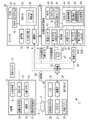
- FIG. 1 It is a figure which shows an example of the structure of the X-ray photography system which concerns on 1st Embodiment. It is a block diagram which shows an example of the hardware composition of the X-ray photography system which concerns on 1st Embodiment. It is a figure which shows an example of a console screen. It is a figure which shows an example of the file format of an image file. It is a figure which shows an example of the personal information deletion processing. It is a figure which conceptually shows an example of personal information deletion processing and CAD processing. It is a figure explaining an example of the learning phase which trains a detection model by machine learning. It is a flowchart which shows an example of the processing flow of an X-ray source and an electronic cassette.
- FIG. 1 shows an example of the configuration of an X-ray imaging system 2 that uses X-rays as radiation.
- the X-ray imaging system 2 that uses X-rays as radiation includes an X-ray source 10, an electronic cassette 20, a console 30, an image diagnosis support device 40, and a repeater 50.
- the console 30 communicates with the electronic cassette 20 and the diagnostic imaging support device 40 via the repeater 50.
- the repeater 50 functions as, for example, an access point.
- the X-ray source 10 is an example of a radiation source that generates radiation.
- the electronic cassette 20 is an example of a radiation image detector that detects radiation and generates a radiation image.
- the diagnostic imaging support device 40 performs CAD processing for detecting a region including an abnormal shadow from a radiographic image.
- the X-ray source 10, the electronic cassette 20, the console 30, and the diagnostic imaging support device 40 of the present embodiment are all small and portable devices.
- the X-ray imaging system 2 can carry these to the site where emergency medical treatment such as an accident or disaster is required, or to the home of a patient who receives home medical care, and can perform X-ray imaging. According to such a portable X-ray imaging system 2, the captured X-ray image can be immediately confirmed on the spot, and re-shooting accompanied by a revisit at a later date can be prevented.
- the X-ray image is an example of a "medical image" according to the technique of the present disclosure.
- the electronic cassette 20 is arranged at a position facing the X-ray source 10.
- the subject H By arranging the subject H between the X-ray source 10 and the electronic cassette 20, it is possible to take an X-ray image of the inspection site (for example, the chest) of the subject H.
- the X-ray source 10 is held by, for example, a holding device 60.
- the holding device 60 is, for example, a quadruped having four support legs 61 and a horizontal bar 62. The upper end of the support leg 61 and both ends of the horizontal bar 62 are connected to the trifurcated joint 63, whereby the holding device 60 is assembled.
- the horizontal bar 62 is provided with an attachment 64 for mechanically attaching the X-ray source 10.
- the X-ray source 10 is suspended by a fixture 64 so that the irradiation direction of the X-ray 4 faces downward.
- the irradiation switch 11 is connected to the X-ray source 10 via the cable 11A.
- a user such as a radiologist or a doctor who uses the X-ray imaging system 2 can start irradiation of the X-ray source 10 with the X-ray source 10 by operating the irradiation switch 11.
- the electronic cassette 20 has an automatic X-ray detection function for detecting the start of irradiation of the X-ray 4 emitted from the X-ray source 10. Therefore, the electronic cassette 20 does not need to be connected to the X-ray source 10. Further, since the electronic cassette 20 has a built-in battery and a wireless communication function, it is not necessary to connect the electronic cassette 20 to the power supply or the console 30 via a cable.
- the electronic cassette 20 is wirelessly connected to the repeater 50 and communicates with the console 30 via the repeater 50.
- the console 30 is composed of, for example, a personal computer, and has a display unit 31 and an input operation unit 32.
- the console 30 is connected to the repeater 50 via, for example, a communication cable 51.
- the display unit 31 is a display device such as a liquid crystal display or an organic EL (Electro Luminescence) display.
- the input operation unit 32 is an input device including a keyboard, a mouse, a touch pad, and the like.
- the user can input patient information, imaging conditions, etc. by operating the input operation unit 32.
- the X-ray image received by the console 30 from the X-ray source 10 is displayed on the display unit 31.
- the user observes the X-ray image and determines that the CAD processing is necessary the user can input the execution request of the CAD processing by using the input operation unit 32.
- the console 30 communicates with the diagnostic imaging support device 40 via the repeater 50.
- the console 30 transmits a CAD processing request to the diagnostic imaging support device 40 in response to an operation signal input by the user via the input operation unit 32.
- the console 30 transmits an X-ray image to the diagnostic imaging support device 40 together with the CAD processing request.
- the console 30 receives the CAD processing result from the diagnostic imaging support device 40, the console 30 causes the display unit 31 to display an X-ray image reflecting the CAD processing result.
- the diagnostic imaging support device 40 has a housing 41 having a size that can be carried by the user.
- the housing 41 is, for example, a box-shaped case having a length, width, and height of 20 cm or less.
- the housing 41 is provided with a power switch 42, a first connector 43A, a second connector 43B, and a third connector 43C.
- the first connector 43A is a terminal having a USB (Universal Serial Bus) type A interface (hereinafter referred to as USB-A I / F).
- the second connector 43B is a terminal having a LAN (Local Area Network) interface (hereinafter referred to as LAN I / F).
- the third connector 43C is a terminal having a USB type C interface (hereinafter referred to as USB-C I / F).
- the housing 41 does not have a display for displaying an X-ray image. Further, the housing 41 does not have a user interface operated by the user to input information.
- the user interface is, for example, a physical operation button or a touch panel.
- the housing 41 has a connector for connecting a display as an external device (for example, an HDMI (registered trademark) (High-Definition Multimedia Interface) terminal) and a connector for connecting a keyboard or the like as an external device (for example). For example, it may be provided with a USB terminal).
- the diagnostic imaging support device 40 is wirelessly or wiredly connected to the repeater 50.
- the diagnostic imaging support device 40 is wirelessly connected to the repeater 50.
- the wireless dongle 70 is, for example, a WiFi_USB adapter that enables communication by WiFi.
- the diagnostic imaging support device 40 communicates with the console 30 via the repeater 50.
- the console 30 is an example of an "external device" according to the technique of the present disclosure.
- the second connector 43B is used when the diagnostic imaging support device 40 and the repeater 50 are connected by wire via a LAN cable (not shown).
- a LAN cable (not shown).
- the third connector 43C corresponds to the power supply standard of USB_PD (Power Delivery).
- a mobile battery 80 can be connected to the third connector 43C via a USB cable 81 corresponding to USB_PD.
- the mobile battery 80 can supply electric power to the inside of the diagnostic imaging support device 40 and the built-in battery built in the diagnostic imaging support device 40.
- the mobile battery 80 supplies DC power to the diagnostic imaging support device 40.
- the third connector 43C can be connected to an AC (Alternating Current) adapter (not shown) instead of the mobile battery 80.
- the third connector 43C can be connected to the AC adapter via the USB cable 81, and the AC adapter can be connected to a commercial AC power source such as a general household.
- the diagnostic imaging support device 40 can receive power converted into direct current from the commercial AC power supply by the AC adapter.
- FIG. 2 shows an example of the hardware configuration of the X-ray imaging system 2.
- the X-ray source 10 includes a processor 12, an input operation unit 13, a built-in battery 14, a high voltage generator 15, an X-ray tube 16, and an irradiation field limiting device 17.
- the processor 12 functions as a control unit that controls the operation of the high voltage generator 15 and the irradiation field limiting device 17.
- the irradiation switch 11 described above is connected to the processor 12.
- the input operation unit 13 is connected.
- the input operation unit 13 has an imaging condition adjustment button for setting the tube voltage and tube current of the X-ray tube 16, an irradiation field button for adjusting the size of the irradiation field of the irradiation field limiting device 17, and a power button. Etc. are included.
- the processor 12 controls the high voltage generator 15 and the irradiation field limiting device 17 based on the setting conditions set by the input operation unit 13.
- the processor 12 generates a high voltage in the high voltage generator 15 in response to the operation of the irradiation switch 11.
- the built-in battery 14 is a secondary battery such as a lithium polymer battery, and can be charged via a connector (not shown).
- the X-ray tube 16 is a fixed anode type X-ray tube having no target rotation mechanism.
- the X-ray tube 16 is composed of a cold cathode electron source that emits electrons, an electron accelerator, a target that generates X-rays 4 by collision of electrons, and an outer tube that houses them.
- the cold cathode electron source does not require a filament and a heater for heating the filament as in the case of a hot cathode.
- the X-ray tube 16 is compact and lightweight because it does not have a rotation mechanism for the target and does not have a filament or a heater. Further, since the X-ray tube 16 does not require residual heat of the filament, it is possible to generate X-rays 4 in response to the irradiation start instruction.
- the irradiation field limiting device 17 limits the irradiation field of the X-ray 4 generated by the X-ray tube 16.
- the X-ray 4 generated by the X-ray tube 16 is irradiated to the inspection site of the subject H by limiting the irradiation field by the irradiation field limiting device 17.
- the X-rays 4 that have passed through the inspection portion of the subject H are incident on the electronic cassette 20.
- the electronic cassette 20 includes a processor 21, an X-ray detection panel 22, a memory 23, a communication I / F 24, and a built-in battery 25.
- the processor 21 functions as a control unit that controls each unit in the electronic cassette 20.
- the X-ray detection panel 22 is, for example, a flat panel detector having a matrix substrate in which a plurality of pixels including a thin film transistor (TFT) and an X-ray detection element are arranged in two dimensions.
- TFT thin film transistor
- the X-ray detection panel 22 converts the incident X-rays into electric charges by the X-ray detection element and accumulates them in the charge accumulation state in which the TFT is turned off. Then, the X-ray detection panel 22 reads out the charge accumulated in the X-ray detection element to the signal processing circuit in the charge reading state in which the TFT is turned on. In the signal processing circuit, the read charge is converted into a voltage signal by an integrating amplifier, and the converted voltage signal is A / D converted by an A / D converter to generate digital image data.
- this image data is referred to as an X-ray image XP.
- the memory 23 is a non-volatile memory such as a flash memory, and stores the X-ray image XP generated by the X-ray detection panel 22.
- the communication I / F 24 is wirelessly connected to the repeater 50.
- the processor 21 transmits the X-ray image XP stored in the memory 23 to the console 30 via the repeater 50. It is also possible to wire-connect the electronic cassette 20 to the repeater 50 via a communication cable.
- the built-in battery 25 is a secondary battery such as a lithium polymer battery, and can be charged via a connector (not shown).
- the console 30 includes a display unit 31, an input operation unit 32, a processor 33, a RAM (RandomAccessMemory) 34, a non-volatile memory (NVM: Non-VolatileMemory) 35, and a communication I / F 36.
- the processor 33 is, for example, a CPU (Central Processing Unit).
- the RAM 34 is a work memory for the processor 33 to execute processing.
- the NVM 35 is a storage device such as a flash memory and stores the program 37.
- the processor 33 functions as a console control unit 38 that collectively controls each part of the console 30 by loading the program 37 stored in the NVM 35 into the RAM 34 and executing processing according to the program 37.
- the console control unit 38 enables input of patient information, imaging conditions, and the like using the input operation unit 32.
- the console control unit 38 causes the display unit 31 to display the X-ray image XP received from the electronic cassette 20.
- the doctor can make a diagnosis based on the X-ray image XP displayed on the display unit 31, but in order to narrow down the candidates for abnormal shadows including lesions from the X-ray image XP, the input operation unit A CAD process execution request can be input using 32.
- console control unit 38 creates an image file PF by adding incidental information including patient information and imaging conditions to the X-ray image XP. Further, the console control unit 38 performs a personal information deletion process for deleting personal information from the image file PF based on an instruction transmitted from the image diagnosis support device 40.
- the communication I / F 36 is wiredly connected to the repeater 50 via the communication cable 51 (see FIG. 1).
- the console control unit 38 transmits the CAD processing request and the image file PF including the X-ray image XP to the image diagnosis support device 40 via the communication I / F 36. It is also possible to wirelessly connect the console 30 to the repeater 50. Further, the console 30 may be, for example, a mobile terminal such as a tablet terminal or a smartphone, in addition to a laptop personal computer equipped with a battery.
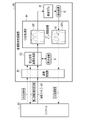
- the diagnostic imaging support device 40 has a processor 44, a RAM 45, an NVM 46, a power feeding unit 47, and a built-in power switch 42, a first connector 43A, a second connector 43B, and a third connector 43C in the housing 41. It includes a battery 48.
- the processor 44 is composed of, for example, a CPU and a GPU (Graphics Processing Unit).
- the RAM 45 is a work memory for the processor 44 to execute processing.
- the NVM 46 is a storage device such as a flash memory, and stores the program 90 and the detection model 91.
- the NVM 46 also stores data such as an image file PF transmitted from the console 30.
- the NVM46 is an example of a "memory" according to the technique of the present disclosure.
- the processor 44 loads the program 90 stored in the NVM 46 into the RAM 45 and executes processing according to the program 90, thereby functioning as a communication processing unit 92, a prohibition instruction transmission processing unit 93, and a CAD processing unit 94.
- the communication processing unit 92 controls communication with the console 30 via the first connector 43A or the second connector 43B. Specifically, the communication processing unit 92 performs communication processing in which the image file PF is received from the console 30 and information including the CAD processing result is transmitted to the console 30.
- the prohibition instruction transmission processing unit 93 transmits an instruction (hereinafter referred to as a transmission prohibition instruction) to the console 30 to prohibit transmission of an image file PF containing personal information unnecessary for CAD processing as incidental information. Perform transmission processing.
- the CAD processing unit 94 performs CAD processing on the X-ray image XP included in the image file PF using the detection model 91 stored in the NVM 46.
- the detection model 91 is a trained model trained by machine learning.
- the detection model 91 is configured using a neural network.
- the detection model 91 is configured by using, for example, a deep neural network (DNN), which is a multi-layer neural network that is a target of deep learning.
- DNN deep neural network
- CNN convolutional neural network
- the power feeding unit 47 supplies the electric power supplied from the mobile battery 80 to the processor 44 and the like via the third connector 43C.
- the power feeding unit 47 includes, for example, a power supply circuit and a charge control circuit.
- the power supply circuit regulates the electric power supplied from the mobile battery 80 and supplies it to the processor 44 and the like.
- the charge control circuit controls charging of the built-in battery 48 by the electric power supplied from the mobile battery 80.
- the built-in battery 48 is a secondary battery such as a lithium polymer battery.
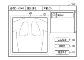
- FIG. 3 shows an example of a console screen displayed on the display unit 31 of the console 30 by the console control unit 38.
- the console screen 100 shown in FIG. 3 is displayed on the display unit 31 after X-ray photography is performed by the X-ray source 10 and the electronic cassette 20 and the console 30 receives from the electronic cassette 20.
- the console screen 100 is provided with an image display area 101 for displaying the X-ray image XP.
- a shooting end button 102 for completing shooting a next shooting button 103 for performing the next shooting
- a CAD processing button 104 for performing a CAD processing request are displayed on the console screen 100.
- a doctor or the like presses the CAD processing button 104 as the input operation unit 32, for example, by operating a mouse.
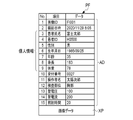
- the console control unit 38 stores the X-ray image XP in the NVM 46 as an image file PF in a format compliant with the DICOM (Digital Imaging and Communication in Medicine) standard as shown in FIG. 4, for example.
- the image file PF is a file in which the X-ray image XP and the incidental information AD are associated with one image ID.
- the incidental information AD includes patient information, a reception number, an examination site, imaging conditions, and the like.
- items 3 to 9 patient name, patient ID, gender, date of birth, age, height, and weight
- personal information refers to information unique to the person to be diagnosed who has acquired a medical image. Personal information is not limited to the information shown in items 3 to 9.
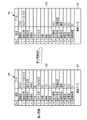
- FIG. 5 shows an example of personal information deletion processing executed by the console control unit 38.
- the console control unit 38 executes the personal information deletion process in response to an instruction from the console 30, the personal information is obtained by deleting all the personal information included in the incidental information AD of the image file PF. Generate the deleted image file PF.
- the console control unit 38 deletes the data of items 3 to 9 corresponding to the personal information.
- the console control unit 38 may add dummy data to items 3 to 9 from which personal information has been deleted. That is, personal information may be deleted by replacing it with dummy data.
- the image file PF from which the personal information has been deleted is a DICOM format file like the image file PF before the personal information has been deleted.
- FIG. 6 conceptually shows an example of the processing executed by the diagnostic imaging support device 40.
- a "CAD processing request" is transmitted from the console 30 to the diagnostic imaging support device 40.
- the communication processing unit 92 receives the CAD processing request from the console 30, the communication processing unit 92 inputs the received CAD processing request to the prohibition instruction transmission processing unit 93.
- the prohibition instruction transmission processing unit 93 generates "personal information transmission availability information" indicating whether or not transmission of personal information is permitted based on the setting information S, and the generated personal information transmission availability information is used in the communication processing unit. It is transmitted to the console 30 via 92.
- the setting information S is data indicating whether or not to allow the console 30 to transmit the image file PF including personal information, and is stored in, for example, NVM46 (see FIG. 2).
- the setting information S is preset by the administrator of the X-ray imaging system 2 or the like.
- the prohibition instruction transmission processing unit 93 transmits the transmission prohibition instruction to the console 30 as the personal information transmission possibility information.
- the console control unit 38 of the console 30 transmits the image file PF from which the personal information has been deleted to the image diagnosis support device 40.
- the console control unit 38 transmits the image file PF from which the personal information has not been deleted to the image diagnosis support device 40.
- the communication processing unit 92 When the communication processing unit 92 receives the image file PF from the console 30, the image file PF is input to the CAD processing unit 94 via the prohibition instruction transmission processing unit 93.
- the CAD processing unit 94 inputs the X-ray image XP included in the image file PF into the detection model 91.
- the detection model 91 detects a region including an abnormal shadow from the input X-ray image XP, and outputs the detection result R.
- the detection result R includes the position information of the region including the abnormal shadow in the X-ray image XP.
- the CAD processing unit 94 generates a processed X-ray image XPC by performing image processing on the X-ray image XP based on the detection result R. For example, the CAD processing unit 94 generates a processed X-ray image XPC by superimposing a circular mark M surrounding an abnormal shadow on the X-ray image XP based on the detection result R. The CAD processing unit 94 transmits the processed X-ray image XPC to the console 30 via the communication processing unit 92 as the CAD processing result.
- the CAD processing unit 94 may transmit only the information representing the detection result R to the console 30 as the CAD processing result. In this case, image processing may be performed on the X-ray image XP in the console 30 based on the detection result R.
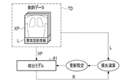
- FIG. 7 illustrates an example of a learning phase in which the detection model 91 is trained by machine learning.
- the detection model 91 learns using the teacher data TD.
- the teacher data TD includes an X-ray image XP as a plurality of teacher images with the correct label L.
- the X-ray image XP included in the teacher data TD is a sample image including various abnormal shadows.
- the correct label L is, for example, position information of an abnormal shadow in the X-ray image XP.
- the X-ray image XP as a teacher image is input to the detection model 91.
- the detection model 91 outputs the detection result R based on the input X-ray image XP. Based on this detection result R and the correct label L, a loss operation using a loss function is performed. Then, various coefficients (weighting coefficient, bias, etc.) of the detection model 91 are updated according to the result of the loss calculation, and the detection model 91 is updated according to the update settings.
- the learning phase a series of processes of inputting the teacher image to the detection model 91, outputting the detection result R from the detection model 91, loss calculation, update setting, and updating the detection model 91 are repeatedly performed.
- the repetition of this series of processes ends when the detection accuracy reaches a predetermined set level.
- the detection model 91 whose detection accuracy has reached the set level in this way is stored in the NVM 46 and then used by the CAD processing unit 94 in the CAD processing which is the operation phase (also referred to as the inference phase).
- the learning phase is executed, for example, on a computer different from the diagnostic imaging support device 40.
- the detection model 91 generated by another computer is transmitted to the diagnostic imaging support device 40 and stored in the NVM 46.
- the learning phase may be executed in the diagnostic imaging support device 40.
- the detection model 91 may be generated for each examination site (chest, abdomen, etc.). That is, the NVM 46 may store a plurality of detection models 91 generated for each inspection site.
- the CAD processing unit 94 may refer to the inspection site included in the incidental information AD (see FIG. 5) of the image file PF to be CAD processed, and select the detection model 91 according to the inspection site.
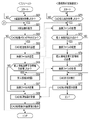
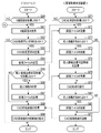
- FIG. 8 shows an example of the processing flow of the X-ray source 10 and the electronic cassette 20.
- FIG. 9 shows an example of the processing flow of the console 30 and the diagnostic imaging support device 40.
- a user Prior to imaging, a user such as a doctor performs an operation of inputting imaging conditions, patient information, etc. to the X-ray source 10 and the console 30. Next, the subject H is arranged between the X-ray source 10 and the electronic cassette 20.
- the user operates the irradiation switch 11 to cause the X-ray source 10 to start irradiation of the X-ray 4.
- the processor 12 of the X-ray source 10 determines whether or not the irradiation switch 11 is pressed by the user (step S10).
- the processor 12 determines that the irradiation switch 11 is pressed (step S10: YES)
- the processor 12 generates X-rays 4 in the X-ray tube 16 by generating a high voltage in the high voltage generator 15 (step S10: YES). S11).
- the electronic cassette 20 is irradiated with X-rays 4 from the X-ray source 10 via the subject H.
- the processor 21 of the electronic cassette 20 determines whether or not X-ray irradiation is detected by the automatic X-ray detection function (step S20). When the processor 21 determines that the X-ray irradiation is detected (step S20: YES), the processor 21 causes the X-ray detection panel 22 to generate an X-ray image XP (step S21). Then, the processor 21 transmits the X-ray image XP to the console 30 via the communication I / F 24 (step S22).
- the console control unit 38 determines whether or not the X-ray image XP has been received from the electronic cassette 20 (step S30).
- the console control unit 38 displays the X-ray image XP on the console screen 100 (see FIG. 3) (step S31).
- the console control unit 38 determines whether or not the CAD processing button 104 has been pressed by the user (step S32).
- the console control unit 38 ends the processing.
- step S32 determines that the CAD processing button 104 has been pressed
- step S33 the console control unit 38 transmits a CAD processing request to the diagnostic imaging support device 40
- step S34 the console control unit 38 receives personal information transmission availability information from the diagnostic imaging support device 40
- step S35 determines whether or not the received personal information transmission availability information includes a transmission prohibition instruction
- step S35 When the console control unit 38 determines that the transmission prohibition instruction is included in the personal information transmission availability information (step S35: YES), the console control unit 38 deletes the personal information from the incidental information AD as shown in FIG. 5 (step S36). ), The image file PF from which the personal information has been deleted is transmitted to the image diagnosis support device 40 (step S37). On the other hand, when the console control unit 38 determines that the transmission prohibition instruction is not included in the personal information transmission possibility information (step S35: NO), the image file PF (see FIG. 4) in which the personal information is not deleted is selected. It is transmitted to the image diagnosis support device 40 (step S37).
- the console control unit 38 receives the processed X-ray image XPC (see FIG. 6) as the CAD processing result from the image diagnosis support device 40 (step S38), and the received processed X-ray image XPC console screen 100. Is displayed (step S39).
- the communication processing unit 92 determines whether or not a CAD processing request has been received from the console 30 (step S40).
- the communication processing unit 92 determines that the CAD processing request has been received (step S40: YES)
- the prohibition instruction transmission processing unit 93 transmits personal information transmission availability information to the console 30 (step S41).
- the communication processing unit 92 receives the image file PF transmitted from the console 30 in step S37 described above (step S42).
- the CAD processing unit 94 executes CAD processing on the X-ray image XP included in the image file PF (step S43).
- the CAD processing unit 94 generates a processed X-ray image XPC by executing the CAD processing using the detection model 91 (see FIG. 6).
- the communication processing unit 92 transmits the processed X-ray image XPC as a CAD processing result to the console 30 (step S44).
- the X-ray imaging system 2 includes an image diagnosis support device 40 that is portable by the user and can be powered by the mobile battery 80, the image diagnosis support device is provided in the field of disaster medical care or home medical care. It can be performed.
- the diagnostic imaging support device 40 since the diagnostic imaging support device 40 is portable, there is a risk of theft. However, since the image diagnosis support device 40 is configured to be able to send an instruction to the console 30 to prohibit the transmission of the image file PF containing the personal information unnecessary for the CAD process in the incidental information. It is possible to prevent the leakage of personal information.
- FIG. 10 is a flowchart showing an example of processing executed by the diagnostic imaging support device 40 according to the modified example of the first embodiment.
- the flowchart shown in FIG. 10 is obtained by adding steps S50 to S52 between steps S42 and S43 of the flowchart shown in FIG.
- steps S50 to S52 between steps S42 and S43 of the flowchart shown in FIG.
- the communication processing unit 92 receives the image file PF transmitted from the console 30 (step S42).
- the prohibition instruction transmission processing unit 93 determines whether or not the image file PF received by the communication processing unit 92 contains personal information unnecessary for CAD processing (step S50).
- This personal information is information for which the transmission prohibition instruction included in the personal information transmission possibility information transmitted by the prohibition instruction transmission processing unit 93 in step S41 is subject to transmission prohibition.
- the prohibition instruction transmission processing unit 93 determines that the image file PF does not contain personal information unnecessary for the CAD processing (step S50: NO)
- the CAD processing unit 94 causes the CAD processing unit 94 to execute the CAD processing (step S43). ..
- the prohibition instruction transmission processing unit 93 determines that the image file PF contains personal information unnecessary for CAD processing (step S50: YES)
- the prohibition instruction transmission processing unit 93 discards the image file PF (step S51).
- the communication processing unit 92 rejects the reception of data from the console 30 (that is, cuts off the communication) (step S52). This completes the process.
- the diagnostic imaging support device 40 transmits personal information transmission availability information to the console 30 before receiving the image file PF from the console 30.
- the diagnostic imaging support device 40 receives the image file PF from the console 30 and then transmits the personal information transmission availability information to the console 30.
- FIG. 11 is a flowchart showing an example of processing executed by the console 30 and the diagnostic imaging support device 40 according to the second embodiment.
- Steps S60 to S63 are the same processes as steps S30 to S33 in the flowchart shown in FIG.
- the console control unit 38 of the console 30 transmits the CAD processing request to the image diagnosis support device 40 in step S63, and then transmits the image file PF to the image diagnosis support device 40 (step S64).
- the communication processing unit 92 receives the image file PF transmitted from the console 30 after determining that the CAD processing request has been received (step S70: YES) (step S71).
- the prohibition instruction transmission processing unit 93 determines whether or not the image file PF received by the communication processing unit 92 contains personal information unnecessary for CAD processing (step S72).
- the CAD processing unit 94 causes the CAD processing unit 94 to execute the CAD processing (step S76). ..
- the prohibition instruction transmission processing unit 93 determines that the image file PF contains personal information unnecessary for CAD processing (step S72: YES), the image file PF is discarded (step S73). After that, the prohibition instruction transmission processing unit 93 transmits the personal information transmission possibility information including the transmission prohibition instruction to the console 30 via the communication processing unit 92 (step S74).
- the console control unit 38 determines whether or not personal information transmission availability information has been received from the diagnostic imaging support device 40 (step S65). When the console control unit 38 determines that the personal information transmission availability information has not been received (step S65: NO), the processing shifts to step S68. On the other hand, when the console control unit 38 determines that the personal information transmission enable / disable information has been received (step S65: YES), the console control unit 38 deletes the personal information from the incidental information AD of the image file PF (step S66), and the personal information is released. The deleted image file PF is transmitted to the image diagnosis support device 40 (step S67).
- the communication processing unit 92 receives the image file PF transmitted from the console 30 (step S75). After that, the CAD processing unit 94 executes CAD processing on the X-ray image XP included in the image file PF (step S76). Then, the communication processing unit 92 transmits the processed X-ray image XPC as a CAD processing result to the console 30 (step S77).
- the console control unit 38 receives the processed X-ray image XPC (see FIG. 6) as a CAD processing result from the image diagnosis support device 40 (step S68), and the received processed X-ray image XPC console screen. It is displayed on 100 (step S69).
- FIG. 12 is a flowchart showing an example of processing executed by the diagnostic imaging support device 40 according to the first modification of the second embodiment.
- steps S80 to S82 are added between steps S75 and S76 in the flowchart shown in FIG.
- steps S75 and S76 are added between steps S75 and S76 in the flowchart shown in FIG.
- the communication processing unit 92 receives the image file PF transmitted from the console 30 (step S75).
- the prohibition instruction transmission processing unit 93 determines whether or not the image file PF received by the communication processing unit 92 contains personal information unnecessary for CAD processing (step S80).
- This personal information is information for which the transmission prohibition instruction included in the personal information transmission possibility information transmitted by the prohibition instruction transmission processing unit 93 in step S74 is subject to transmission prohibition.
- the prohibition instruction transmission processing unit 93 determines that the image file PF does not contain personal information unnecessary for the CAD processing (step S80: NO)
- the CAD processing unit 94 causes the CAD processing unit 94 to execute the CAD processing (step S76). ..
- the prohibition instruction transmission processing unit 93 determines that the image file PF contains personal information unnecessary for CAD processing (step S80: YES)
- the prohibition instruction transmission processing unit 93 discards the image file PF (step S81).
- the communication processing unit 92 rejects the reception of data from the console 30 (that is, cuts off the communication) (step S82). This completes the process.
- FIG. 13 is a flowchart showing an example of the processing executed by the diagnostic imaging support device 40 according to the second modification of the second embodiment.
- the flowchart shown in FIG. 13 is obtained by adding step S90 and step S91 between steps S76 and S77 of the flowchart shown in FIG.
- step S90 and step S91 between steps S76 and S77 of the flowchart shown in FIG.
- the communication processing unit 92 receives the image file PF transmitted from the console 30 (step S75).
- the CAD processing unit 94 executes CAD processing on the X-ray image XP included in the image file PF (step S76).
- the prohibition instruction transmission processing unit 93 determines whether or not the image file PF received by the communication processing unit 92 contains personal information (step S90).
- This personal information is information for which the transmission prohibition instruction included in the personal information transmission possibility information transmitted by the prohibition instruction transmission processing unit 93 in step S74 is subject to transmission prohibition.
- step S90: NO the process shifts to step S77.
- step S90: YES the prohibition instruction transmission processing unit 93 discards the image file PF (step S91).
- the communication processing unit 92 transmits the processed X-ray image XPC as a CAD processing result to the console 30 (step S77).
- the image file PF contains personal information unnecessary for the CAD processing
- the image file PF is discarded after the CAD processing, so that the leakage of the personal information can be prevented more reliably. can do.
- the console control unit 38 deletes all the personal information from the incidental information AD of the image file PF, but among the personal information included in the incidental information AD, at least the personal information unnecessary for the CAD process is deleted. You can delete it.
- "Personal information unnecessary for CAD processing" is personal information other than information that may be used for CAD processing.
- the console control unit 38 among the personal information unique to the diagnosis target person, the information for identifying the diagnosis target person such as the patient name and the patient ID is personal information unnecessary for CAD processing.
- FIG. 14 shows an example of deleting a part of personal information from the incidental information AD of the image file PF.
- the data of items other than "date of birth” and "age” are deleted from the personal information. That is, the data of items other than "date of birth” and "age” are personal information unnecessary for CAD processing.
- the NVM46 stores a detection model that supports pediatric diagnosis and a detection model that does not support pediatric diagnosis.
- the CAD processing unit 94 can determine whether or not to use a detection model that supports pediatric diagnosis by referring to the "age" included in the incidental information AD of the image file PF from which the personal information has been deleted.
- the CAD processing unit 94 uses a detection model that supports pediatric diagnosis, for example, when the age is less than 15 years.
- the prohibition instruction transmission processing unit 93 may determine the personal information to be prohibited from transmission from the incidental information AD of the image file PF by referring to the table in which the personal information to be prohibited from transmission is recorded. This table is stored in, for example, NVM46.
- the detection model 91 in the learning phase (see FIG. 7) in which the detection model 91 is learned by machine learning, the detection model 91 is trained using the teacher data TD including the X-ray image XP and the correct answer label L. There is. Further, the detection model 91 may be trained using the teacher data TD including a part of personal information (for example, gender, age, height, weight). In this case, the CAD processing unit 94 inputs a part of personal information to the detection model 91 in addition to the X-ray image XP in the CAD processing.
- the X-ray source 10 is portable in each of the above embodiments, the X-ray source 10 may be an X-ray source used in a general X-ray imaging system.
- the X-ray source 10 is movably held by, for example, a ceiling-type holding device.
- the electronic cassette 20 is used by being attached to an imaging table.
- the X-ray imaging system 2 may use a so-called mobile round-trip vehicle. Further, the X-ray imaging system 2 may be a mammography apparatus, CT (Computed Tomography), or the like.
- the technique of the present disclosure can be applied not only to X-rays but also to a system for photographing a subject using other radiation such as ⁇ -rays.
- the diagnostic imaging support device 40 can also be applied to an ultrasonic imaging system that generates an image by ultrasonic waves. That is, the diagnostic imaging support device 40 may perform CAD processing on an ultrasonic image as a medical image.
- the CAD processing unit 94 performs CAD processing using the detection model 91, which is a learned model generated by machine learning, but the CAD processing unit is not limited to the method by machine learning and is performed by image analysis. It may be software that performs CAD processing. Further, in each of the above embodiments, the CAD processing unit 94 detects the abnormal shadow by the CAD processing, but may detect a portion other than the abnormal shadow. For example, the CAD processing unit 94 may detect blood vessels from the ultrasonic image when the CAD processing is performed on the ultrasonic image.
- the X-ray imaging system 2 is provided with the repeater 50, but the repeater 50 is not essential, and the console 30 may have the function of the repeater.
- the hardware structure of the processing unit (processing unit) that executes various processes such as the communication processing unit 92, the prohibition instruction transmission processing unit 93, and the CAD processing unit 94 is as shown below.
- processing unit processing unit
- Various processors Various processors.
- processors include a CPU, a programmable logic device (PLD: Programmable Logic Device), a dedicated electric circuit, and the like.
- a CPU is a general-purpose processor that executes software (program) and functions as various processing units.
- PLD is a processor such as FPGA (Field Programmable Gate Array) whose circuit configuration can be changed after manufacturing.
- a dedicated electric circuit is a processor having a circuit configuration specially designed for executing a specific process such as an ASIC (Application Specific Integrated Circuit).
- One processing unit may be composed of one of these various processors, or may be composed of a combination of two or more processors of the same type or different types (for example, a plurality of FPGAs or a combination of a CPU and an FPGA). May be done. Further, a plurality of processing units may be configured by one processor. As an example of configuring a plurality of processing units with one processor, first, there is a mode in which one processor is configured by a combination of one or more CPUs and software, and this processor functions as a plurality of processing units. Secondly, as typified by a system on chip (SoC), there is a mode in which a processor that realizes the functions of the entire system including a plurality of processing units with one IC chip is used. As described above, the various processing units are configured by using one or more of the above-mentioned various processors as a hardware-like structure.
- SoC system on chip
- the hardware-like structure of these various processors is, more specifically, an electric circuit (circuitry) in which circuit elements such as semiconductor elements are combined.
- the present invention is not limited to each of the above embodiments, and various configurations can be adopted as long as the gist of the present invention is not deviated. Further, in addition to the program, the present invention extends to a computer-readable storage medium that stores the program non-temporarily.
Landscapes
- Health & Medical Sciences (AREA)
- Engineering & Computer Science (AREA)
- Medical Informatics (AREA)
- General Health & Medical Sciences (AREA)
- Public Health (AREA)
- Nuclear Medicine, Radiotherapy & Molecular Imaging (AREA)
- Radiology & Medical Imaging (AREA)
- Epidemiology (AREA)
- Primary Health Care (AREA)
- Life Sciences & Earth Sciences (AREA)
- Biomedical Technology (AREA)
- Physics & Mathematics (AREA)
- Pathology (AREA)
- Computer Vision & Pattern Recognition (AREA)
- General Physics & Mathematics (AREA)
- Theoretical Computer Science (AREA)
- Quality & Reliability (AREA)
- High Energy & Nuclear Physics (AREA)
- Databases & Information Systems (AREA)
- Biophysics (AREA)
- Data Mining & Analysis (AREA)
- Optics & Photonics (AREA)
- Heart & Thoracic Surgery (AREA)
- Molecular Biology (AREA)
- Surgery (AREA)
- Animal Behavior & Ethology (AREA)
- Veterinary Medicine (AREA)
- Apparatus For Radiation Diagnosis (AREA)
Priority Applications (2)
| Application Number | Priority Date | Filing Date | Title |
|---|---|---|---|
| JP2022571656A JP7797418B2 (ja) | 2020-12-24 | 2021-12-23 | 画像診断支援装置、画像診断支援装置の作動方法、及びプログラム |
| US18/336,020 US20230326579A1 (en) | 2020-12-24 | 2023-06-16 | Image diagnosis support device, operation method for image diagnosis support device, and program |
Applications Claiming Priority (2)
| Application Number | Priority Date | Filing Date | Title |
|---|---|---|---|
| JP2020215535 | 2020-12-24 | ||
| JP2020-215535 | 2020-12-24 |
Related Child Applications (1)
| Application Number | Title | Priority Date | Filing Date |
|---|---|---|---|
| US18/336,020 Continuation US20230326579A1 (en) | 2020-12-24 | 2023-06-16 | Image diagnosis support device, operation method for image diagnosis support device, and program |
Publications (1)
| Publication Number | Publication Date |
|---|---|
| WO2022138877A1 true WO2022138877A1 (ja) | 2022-06-30 |
Family
ID=82158062
Family Applications (1)
| Application Number | Title | Priority Date | Filing Date |
|---|---|---|---|
| PCT/JP2021/048047 Ceased WO2022138877A1 (ja) | 2020-12-24 | 2021-12-23 | 画像診断支援装置、画像診断支援装置の作動方法、及びプログラム |
Country Status (3)
| Country | Link |
|---|---|
| US (1) | US20230326579A1 (cg-RX-API-DMAC7.html) |
| JP (1) | JP7797418B2 (cg-RX-API-DMAC7.html) |
| WO (1) | WO2022138877A1 (cg-RX-API-DMAC7.html) |
Cited By (1)
| Publication number | Priority date | Publication date | Assignee | Title |
|---|---|---|---|---|
| JP2024038836A (ja) * | 2022-09-08 | 2024-03-21 | 株式会社モリタ東京製作所 | 診断システム、情報処理装置、および、プログラム |
Families Citing this family (1)
| Publication number | Priority date | Publication date | Assignee | Title |
|---|---|---|---|---|
| JP7873612B2 (ja) * | 2022-09-30 | 2026-06-12 | 株式会社コラボスクエア | 医療関係者向け情報伝達システム、情報伝達方法、及び医療関係者向け情報提供システム |
Citations (3)
| Publication number | Priority date | Publication date | Assignee | Title |
|---|---|---|---|---|
| JP2003256570A (ja) * | 2002-03-06 | 2003-09-12 | Takuo Tsujimura | 画像診断支援システム |
| JP2005122237A (ja) * | 2003-10-14 | 2005-05-12 | Olympus Corp | 検査装置管理方法及びサーバ装置 |
| JP2006158725A (ja) * | 2004-12-08 | 2006-06-22 | Toshiba Corp | 医用画像出力システム、医用画像出力方法、その医用画像出力方法をコンピュータに実行させるプログラム、及び、そのプログラムをコンピュータ読み取り可能に記憶した記憶媒体 |
Family Cites Families (5)
| Publication number | Priority date | Publication date | Assignee | Title |
|---|---|---|---|---|
| US7231071B2 (en) * | 2001-09-13 | 2007-06-12 | Fujifilm Corporation | Abnormal shadow detecting system |
| US20040221016A1 (en) * | 2003-05-01 | 2004-11-04 | Hatch James A. | Method and apparatus for preventing transmission of unwanted email |
| US20160241766A1 (en) | 2015-02-12 | 2016-08-18 | International Business Machines Corporation | Method of disabling transmission and capture of visual content on a device to protect from inappropriate content |
| NL2020723B1 (en) * | 2018-04-05 | 2019-10-14 | Teeuwen Jaap | Digital image analysis and transfer system |
| US20190341150A1 (en) * | 2018-05-01 | 2019-11-07 | Google Llc | Automated Radiographic Diagnosis Using a Mobile Device |
-
2021
- 2021-12-23 WO PCT/JP2021/048047 patent/WO2022138877A1/ja not_active Ceased
- 2021-12-23 JP JP2022571656A patent/JP7797418B2/ja active Active
-
2023
- 2023-06-16 US US18/336,020 patent/US20230326579A1/en active Pending
Patent Citations (3)
| Publication number | Priority date | Publication date | Assignee | Title |
|---|---|---|---|---|
| JP2003256570A (ja) * | 2002-03-06 | 2003-09-12 | Takuo Tsujimura | 画像診断支援システム |
| JP2005122237A (ja) * | 2003-10-14 | 2005-05-12 | Olympus Corp | 検査装置管理方法及びサーバ装置 |
| JP2006158725A (ja) * | 2004-12-08 | 2006-06-22 | Toshiba Corp | 医用画像出力システム、医用画像出力方法、その医用画像出力方法をコンピュータに実行させるプログラム、及び、そのプログラムをコンピュータ読み取り可能に記憶した記憶媒体 |
Cited By (1)
| Publication number | Priority date | Publication date | Assignee | Title |
|---|---|---|---|---|
| JP2024038836A (ja) * | 2022-09-08 | 2024-03-21 | 株式会社モリタ東京製作所 | 診断システム、情報処理装置、および、プログラム |
Also Published As
| Publication number | Publication date |
|---|---|
| JPWO2022138877A1 (cg-RX-API-DMAC7.html) | 2022-06-30 |
| US20230326579A1 (en) | 2023-10-12 |
| JP7797418B2 (ja) | 2026-01-13 |
Similar Documents
| Publication | Publication Date | Title |
|---|---|---|
| JP2016027888A (ja) | コンソールおよび放射線画像撮影システム | |
| US12465309B2 (en) | Imaging support device, and operation method and operation program for the same | |
| JP6766829B2 (ja) | 放射線画像撮影システム、医用画像出力システムおよび出力装置 | |
| US20230326579A1 (en) | Image diagnosis support device, operation method for image diagnosis support device, and program | |
| JPWO2006109551A1 (ja) | 放射線画像撮影システム | |
| JP2026042941A (ja) | 写損判断支援装置及びプログラム | |
| US7664842B2 (en) | Mobile radiography apparatus, control method thereof, and program | |
| CN109843177B (zh) | 放射线摄像系统及其控制方法、控制装置及介质 | |
| JP2011172603A (ja) | 放射線画像撮影システム | |
| JP2017199286A (ja) | 情報処理装置、情報処理システム、情報処理方法及びプログラム。 | |
| CN115297777B (zh) | 移动式放射线产生装置、移动式放射线产生装置的工作方法、存储介质 | |
| JP7835692B2 (ja) | 画像診断支援装置、画像診断支援装置の作動方法、及びプログラム | |
| KR20180046606A (ko) | 방사선 촬영 시스템에서 프로토콜을 재배열하기 위한 장치 및 방법 | |
| US12482099B2 (en) | Image diagnosis support device | |
| JP2024077028A (ja) | 医用情報処理装置、医用情報処理方法およびプログラム | |
| JP7276020B2 (ja) | 医用画像処理装置、医用画像処理方法及びプログラム | |
| US20160147967A1 (en) | Medical support device | |
| JP2011212031A (ja) | 放射線画像撮影システム | |
| JP2006122304A (ja) | 放射線画像撮影システム | |
| US9924918B2 (en) | Control apparatus, control method, and storage medium | |
| CN118526214A (zh) | 信息处理装置、放射线成像系统、信息处理方法、以及非暂时性计算机可读存储介质 | |
| JP5669502B2 (ja) | 放射線画像撮影装置 | |
| JP2024111980A (ja) | 端末制御装置、端末制御方法及び端末制御プログラム | |
| JP2021045359A (ja) | 放射線撮影システム、撮影制御装置、放射線撮影方法及び放射線撮影プログラム | |
| JP2019071989A (ja) | 情報処理装置、その制御方法、およびプログラム |
Legal Events
| Date | Code | Title | Description |
|---|---|---|---|
| 121 | Ep: the epo has been informed by wipo that ep was designated in this application |
Ref document number: 21911016 Country of ref document: EP Kind code of ref document: A1 |
|
| ENP | Entry into the national phase |
Ref document number: 2022571656 Country of ref document: JP Kind code of ref document: A |
|
| NENP | Non-entry into the national phase |
Ref country code: DE |
|
| 122 | Ep: pct application non-entry in european phase |
Ref document number: 21911016 Country of ref document: EP Kind code of ref document: A1 |