WO2022138843A1 - Dispositif de commande numérique - Google Patents
Dispositif de commande numérique Download PDFInfo
- Publication number
- WO2022138843A1 WO2022138843A1 PCT/JP2021/047946 JP2021047946W WO2022138843A1 WO 2022138843 A1 WO2022138843 A1 WO 2022138843A1 JP 2021047946 W JP2021047946 W JP 2021047946W WO 2022138843 A1 WO2022138843 A1 WO 2022138843A1
- Authority
- WO
- WIPO (PCT)
- Prior art keywords
- tool
- path
- additional information
- control device
- numerical control
- Prior art date
Links
- 238000004458 analytical method Methods 0.000 claims abstract description 9
- 238000005520 cutting process Methods 0.000 claims description 25
- 230000036461 convulsion Effects 0.000 claims description 21
- 230000001133 acceleration Effects 0.000 claims description 20
- 230000003746 surface roughness Effects 0.000 claims description 7
- 230000008859 change Effects 0.000 claims description 6
- 238000009499 grossing Methods 0.000 claims description 6
- 238000012545 processing Methods 0.000 abstract description 17
- 238000004364 calculation method Methods 0.000 abstract description 7
- 230000006866 deterioration Effects 0.000 abstract description 4
- 238000003754 machining Methods 0.000 description 12
- 238000011960 computer-aided design Methods 0.000 description 10
- 238000000034 method Methods 0.000 description 8
- 230000006870 function Effects 0.000 description 6
- 238000010586 diagram Methods 0.000 description 5
- 230000008569 process Effects 0.000 description 4
- 238000004891 communication Methods 0.000 description 3
- 238000003860 storage Methods 0.000 description 3
- 230000000694 effects Effects 0.000 description 2
- 230000006872 improvement Effects 0.000 description 2
- 238000004519 manufacturing process Methods 0.000 description 2
- 230000002093 peripheral effect Effects 0.000 description 2
- 238000012937 correction Methods 0.000 description 1
- 238000005516 engineering process Methods 0.000 description 1
- 238000002474 experimental method Methods 0.000 description 1
- 238000007726 management method Methods 0.000 description 1
- 230000003287 optical effect Effects 0.000 description 1
- 230000004044 response Effects 0.000 description 1
- 239000007787 solid Substances 0.000 description 1
Images


Classifications
-
- G—PHYSICS
- G05—CONTROLLING; REGULATING
- G05B—CONTROL OR REGULATING SYSTEMS IN GENERAL; FUNCTIONAL ELEMENTS OF SUCH SYSTEMS; MONITORING OR TESTING ARRANGEMENTS FOR SUCH SYSTEMS OR ELEMENTS
- G05B19/00—Programme-control systems
- G05B19/02—Programme-control systems electric
- G05B19/18—Numerical control [NC], i.e. automatically operating machines, in particular machine tools, e.g. in a manufacturing environment, so as to execute positioning, movement or co-ordinated operations by means of programme data in numerical form
- G05B19/402—Numerical control [NC], i.e. automatically operating machines, in particular machine tools, e.g. in a manufacturing environment, so as to execute positioning, movement or co-ordinated operations by means of programme data in numerical form characterised by control arrangements for positioning, e.g. centring a tool relative to a hole in the workpiece, additional detection means to correct position
-
- G—PHYSICS
- G05—CONTROLLING; REGULATING
- G05B—CONTROL OR REGULATING SYSTEMS IN GENERAL; FUNCTIONAL ELEMENTS OF SUCH SYSTEMS; MONITORING OR TESTING ARRANGEMENTS FOR SUCH SYSTEMS OR ELEMENTS
- G05B19/00—Programme-control systems
- G05B19/02—Programme-control systems electric
- G05B19/18—Numerical control [NC], i.e. automatically operating machines, in particular machine tools, e.g. in a manufacturing environment, so as to execute positioning, movement or co-ordinated operations by means of programme data in numerical form
- G05B19/4093—Numerical control [NC], i.e. automatically operating machines, in particular machine tools, e.g. in a manufacturing environment, so as to execute positioning, movement or co-ordinated operations by means of programme data in numerical form characterised by part programming, e.g. entry of geometrical information as taken from a technical drawing, combining this with machining and material information to obtain control information, named part programme, for the NC machine
-
- G—PHYSICS
- G05—CONTROLLING; REGULATING
- G05B—CONTROL OR REGULATING SYSTEMS IN GENERAL; FUNCTIONAL ELEMENTS OF SUCH SYSTEMS; MONITORING OR TESTING ARRANGEMENTS FOR SUCH SYSTEMS OR ELEMENTS
- G05B2219/00—Program-control systems
- G05B2219/30—Nc systems
- G05B2219/33—Director till display
- G05B2219/33099—Computer numerical control [CNC]; Software control [SWC]
-
- G—PHYSICS
- G05—CONTROLLING; REGULATING
- G05B—CONTROL OR REGULATING SYSTEMS IN GENERAL; FUNCTIONAL ELEMENTS OF SUCH SYSTEMS; MONITORING OR TESTING ARRANGEMENTS FOR SUCH SYSTEMS OR ELEMENTS
- G05B2219/00—Program-control systems
- G05B2219/30—Nc systems
- G05B2219/35—Nc in input of data, input till input file format
- G05B2219/35097—Generation of cutter path, offset curve
-
- G—PHYSICS
- G05—CONTROLLING; REGULATING
- G05B—CONTROL OR REGULATING SYSTEMS IN GENERAL; FUNCTIONAL ELEMENTS OF SUCH SYSTEMS; MONITORING OR TESTING ARRANGEMENTS FOR SUCH SYSTEMS OR ELEMENTS
- G05B2219/00—Program-control systems
- G05B2219/30—Nc systems
- G05B2219/40—Robotics, robotics mapping to robotics vision
- G05B2219/40449—Continuous, smooth robot motion
Definitions
- the present invention relates to a numerical control device.
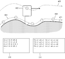
- the CNC (Computerized Manufacturing Control) program 200 generated by the CAM (Computer Aided Manufacturing) device arranges the coordinate values (coordinate values of the command point 403) that the feed axis of the machine tool should pass through, as illustrated in FIG. It is a thing.
- the numerical control device reads the CNC program 200, performs path generation and speed planning according to the commanded coordinate values, and based on the result, drives and controls the drive unit of the machine tool to be controlled along the axis to control the tool.
- the work 401 is machined by moving the 402.
- reference numeral 404 indicates a tool path
- reference numeral 405 indicates a control point path.
- the CAM device creates a tool path from a free curved surface created on a CAD (Computer Aided Design) device and replaces it with a CNC program.
- CAD Computer Aided Design
- the tool path is generally replaced with a set of coordinate values, information about the shape of the CAD model among the coordinate values is lost. Therefore, when controlling a machine tool based on the CNC program, linear interpolation is performed between the coordinate values listed in the CNC program, the original shape and tool path are predicted, and path generation and speed control are performed. (For example, Patent Document 1 etc.).
- the error between the CAD model and the machining result (deterioration of machining accuracy), the deterioration of the machining surface quality due to the fluctuation of the machining speed, and the cycle due to unnecessary deceleration occur.
- Problems such as increased time (occurring as a result of overestimating acceleration) may occur.
- a method may be adopted to reduce the margin of error when generating a CNC program with a CAM device to less than 1 ⁇ m. If such a method is adopted, the CNC program may be adopted.
- Other problems arise, such as increased size and increased calculation time.
- the numerical control device adds additional information about the shape lost when the CAM device generates the CNC program to the CNC program. Additional information to be added may include curvature, radius of curvature, curve function, and the like. Further, the numerical control device according to the present invention uses additional information when executing the CNC program to perform correction processing of command coordinates, interpolation processing between command coordinates, or speed control processing. In these processes, additional information is used directly instead of changing the numerical control parameters. The additional information may be transferred to the numerical control device together with the CNC program (command coordinate value), or may be transferred to the numerical control device by a means different from the CNC program (command coordinate value). ..
- one aspect of the present invention is a numerical control device that controls a machine equipped with the tool based on a CNC program including a plurality of command points for commanding the movement of the tool, the CNC program and additional information of the CNC program. It includes a reading analysis unit that reads the above, a path generation unit that determines the movement path of the tool, and a speed control unit that determines the speed at which the tool is moved according to the movement path of the tool. The additional information is used in the route generation unit to generate a route between command points including the command point.
- the additional information includes the required surface roughness of the work, the dimensions of the drawing, the work shape expressed by the mathematical formula, the jerk of the tool path, the tool path expressed by the mathematical formula, the amount of change in the tool vector, and the tool tip point.
- machining accuracy can be improved without increasing the program size (command coordinate point number) and calculation time.
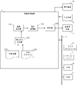
- FIG. 1 is a schematic hardware configuration diagram showing a main part of a numerical control device according to the first embodiment of the present invention.
- the numerical control device 1 has a function of controlling an industrial machine 3 such as a machine tool or a 5-axis machine tool based on a CNC program.
- the CPU 11 included in the numerical control device 1 is a processor that controls the numerical control device 1 as a whole.
- the CPU 11 reads the system program stored in the ROM 12 via the bus 22 and controls the entire numerical control device 1 according to the system program. Temporary calculation data, display data, various data input from the outside, and the like are temporarily stored in the RAM 13.
- the non-volatile memory 14 is composed of, for example, a memory backed up by a battery (not shown), an SSD (Solid State Drive), or the like, and the storage state is maintained even when the power of the numerical control device 1 is turned off.
- the non-volatile memory 14 contains control programs and data read from the external device 72 via the interface 15, control programs and data input from the input device 71 via the interface 18, and a fog computer via the network 5. Control programs, data, and the like acquired from other devices such as 6 and the cloud server 7 are stored.
- the data stored in the non-volatile memory 14 relates to, for example, the position, speed, acceleration, load of each motor included in the industrial machine 3, and each physical quantity detected by a sensor (not shown) attached to the industrial machine 3. Data and the like may be included.
- the control program or data stored in the non-volatile memory 14 may be expanded in the RAM 13 at the time of execution / use. Further, various system programs such as a known analysis program are written in the ROM 12 in advance.
- the interface 15 is an interface for connecting the CPU 11 of the numerical control device 1 and an external device 72 such as an external storage medium. From the external device 72 side, for example, a control program and setting data used for controlling the industrial machine 3 are read. Further, the control program, setting data, etc. edited in the numerical control device 1 can be stored in an external storage medium such as a CF card or a USB memory (not shown) via the external device 72.
- the PLC (programmable logic controller) 16 executes a ladder program and is attached to the industrial machine 3 and peripheral devices of the industrial machine 3 (for example, a tool changer, an actuator such as a robot, or an industrial machine 3). A signal is output and controlled via the I / O unit 19 to a sensor such as a temperature sensor or a humidity sensor. Further, the PLC 16 receives signals from various switches and peripheral devices of the operation panel installed in the main body of the industrial machine 3, performs necessary signal processing, and then passes the signals to the CPU 11.
- the interface 20 is an interface for connecting the CPU 11 of the numerical control device 1 and the wired or wireless network 5.
- the network 5 communicates using technologies such as serial communication such as RS-485, Ethernet (registered trademark) communication, optical communication, wireless LAN, Wi-Fi (registered trademark), and Bluetooth (registered trademark). It may be there.
- Other devices such as CAD device 8 and CAM device 9 and higher-level management devices such as fog computer 6 and cloud server 7 are connected to the network 5, and data is exchanged with and from the numerical control device 1. Is going.
- each data read on the memory, data obtained as a result of executing the program, etc. are output and displayed via the interface 17.
- the input device 71 composed of a keyboard, a pointing device, and the like passes commands, data, and the like based on operations by the operator to the CPU 11 via the interface 18.
- the axis control circuit 30 for driving the drive unit included in the industrial machine 3 along the axis receives a movement command amount related to the axis from the CPU 11 and outputs a command related to the axis to the servo amplifier 40, respectively.
- the servo amplifier 40 drives the servomotors 50 that move the drive unit of the industrial machine 3 along the axis.
- the shaft servomotor 50 has a built-in position / speed detector, and feeds back the position / speed feedback signal from the position / speed detector to the shaft control circuit 30, respectively, to perform position / speed feedback control.
- Only one axis control circuit 30, servo amplifier 40, and servo motor 50 are shown in the hardware configuration diagram of FIG. 1, the axis provided in the industrial machine 3 to be controlled is actually used. As many as the number of are prepared.
- the spindle control circuit 60 receives a spindle rotation command and outputs a spindle speed signal to the spindle amplifier 61.
- the spindle amplifier 61 receives this spindle speed signal and rotates the spindle motor 62 of the industrial machine 3 at the commanded rotation speed.
- a position coder 63 is coupled to the spindle motor 62, the position coder 63 outputs a feedback pulse in synchronization with the rotation of the spindle, and the feedback pulse is read by the CPU 11.
- FIG. 2 shows a schematic block diagram of the functions included in the numerical control device 1 according to the first embodiment of the present invention.
- Each function of the numerical control device 1 according to the present embodiment is realized by the CPU 11 included in the numerical control device 1 shown in FIG. 1 executing a system program and controlling the operation of each part of the numerical control device 1. ..
- the numerical control device 1 of the present embodiment includes a reading analysis unit 100, a route generation unit 110, a speed control unit 120, and a control unit 130. Further, in the RAM 13 to the non-volatile memory 14 of the numerical control device 1, the CNC program 200 used for controlling the industrial machine 3 and the additional information 210 related to the CNC program 200 are stored.
- the read analysis unit 100 executes a system program read from the ROM 12 by the CPU 11 provided in the numerical control device 1 shown in FIG. 1, and performs arithmetic processing mainly by the CPU 11 using the RAM 13 and the non-volatile memory 14. It is realized by.
- the reading analysis unit 100 reads and analyzes the CNC program 200 and the additional information related to the CNC program, and outputs each command included in the CNC program 200 in association with the additional information.
- the additional information 210 associated with each command may include the shape of the work in the range machined by each command, the required quality, the required accuracy, the acceleration and jerk of the tool, and the like.
- the additional information 210 is expressed by the curvature of the work in the range machined by each command, the dimensions of the drawing, the work shape expressed by the mathematical formula, the curvature of the tool path, the jerk of the tool path, and the mathematical formula.
- Tool path change amount of tool vector, curvature of cutting point path, cutting point path expressed by mathematical formula, jerk of cutting point path, required surface roughness of workpiece, preset accuracy level, workpiece requirement It may include accuracy, acceleration of the tool tip point, acceleration of the cutting point path, jerk of the tool tip point, jerk of the cutting point path, and the like.
- the additional information 210 may be created in any format as long as it can be associated with each command of the CNC program 200.
- each position (number of lines, etc.) of the additional information 210 may be created so as to correspond to the position (number of lines, etc.) of each command in the CNC program 200, or the block number. It may be possible to grasp the correspondence by such means. Further, a code or the like may be separately assigned so that the correspondence relationship can be grasped. Further, the additional information 210 may be added in the vicinity of the corresponding command (after the command, etc.) in the CNC program 200. In the example of FIG.
- each axial component of the radius of curvature of X, Y, and Z is shown by Rx, Ry, and Rz as additional information.
- the additional information may indicate information at the command point position.
- the curvature or the like can indicate the curvature at the command point.
- the additional information may indicate information related to the processing of the curve from the previous command point to the command point. For example, when the tool path expressed by a mathematical formula is used as additional information, as illustrated in FIG. 4, the path showing the curve from the previous command point to the command point is set as a parameter with a predetermined parameter.
- ⁇ may be expressed by a mathematical formula, or may be expressed in a range such as a general polynomial represented by x, y, z (including a linear expression), a NURBS curve, an arc function, or the like.
- Formulas, torsions, jerks, etc. are suitable for showing information related to the processing of a curve from a previous command point to the command point.
- the route generation unit 110 is realized by executing a system program read from the ROM 12 by the CPU 11 included in the numerical control device 1 shown in FIG. 1 and performing arithmetic processing mainly by the CPU 11 using the RAM 13 and the non-volatile memory 14. Will be done.
- the route generation unit 110 generates a tool route between command points based on each command included in the CNC program 200 input from the reading analysis unit 100 and the additional information 210 associated with the command.
- the path generation unit 110 is given the radius of curvature R xi , R yi , R zi at the command point P i by the additional information 210 to the cutting command to reach the command point P i , and reaches the command point P i + 1 .
- the command points P i and P i + 1 are set as the start point and the end point, respectively, and the curvature is near the command point P i .
- a curve with radii R xi , R yi , and R zi and curvature radii R xi + 1 , R yi + 1 , and R zi + 1 in the vicinity of the command point P i + 1 is calculated as the tool path.
- the curve of the torsion ⁇ (s) with the plane including the axis direction vector of the tool and the movement direction vector of the tool as the reference plane is used as the tool path.
- a curve having the command points P i and P i + 1 calculated by the mathematical formula as the start point and the end point, respectively, may be calculated as the tool path.
- additional information 210 related to the work and additional information 210 related to the cutting point path are given, the tool path that becomes the specified work shape and cutting point path can be calculated in consideration of the tool length, tool width, etc. good.
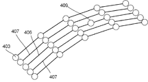
- the route generation unit 110 further adds or deletes command points and corrects the position of the command points when there is a disorder in the sequence of command points composed of a plurality of command points commanded by the CNC program 200 as needed.
- a smoother machined surface may be obtained.
- FIG. 5 it is assumed that there is a command path 406 in which the command point 403 is missing as compared with the adjacent command path 407.
- a command point 408 is added so that the step between the command path 406 and the adjacent command path 407 becomes small.
- an unnecessary command point 409 (although it is within tolerance as compared with a command path when there is no command point or an adjacent command path) as compared with the adjacent command path 407. It is assumed that a redundant point) was included. In such a case, it is possible to determine whether or not the point should be deleted by referring to the curvature, the path equation, etc. given as additional information associated with the command. For example, when the amount of deviation from the equation of the route is large only at the command point 409, or when the curvature of the additional information 210 does not change so much, but the curvature is small or large only in the vicinity of the command point 409 of the command path. By deleting the command point 409, a step between the command point and the adjacent command point is eliminated, and a clean machined surface can be obtained.
- the route generation unit 110 may perform smoothing processing on a command point sequence composed of a plurality of command points. For example, as shown in FIG. 9, when an approximate curve is created from a command point sequence by the least squares method or the like, a deviation may occur between the command point and the approximate curve. When the fluctuation of the curvature in a certain section is small or the curvature changes slowly, it can be judged that the path in this section can be approximated by a low-order polynomial such as a second order or a third order. It is considered that the deviation of the approximate curve is due to some calculation error. Therefore, it can be determined that the tool movement does not need to follow this deviation.
- the route generation unit 110 may perform a smoothing process for smoothing each command point and correcting it to a smooth command path. This smoothing may be performed on an approximate curve, or may be smoothed by applying some sort of filter such as a moving average filter.
- the speed control unit 120 executes a system program read from the ROM 12 by the CPU 11 provided in the numerical control device 1 shown in FIG. 1, and performs arithmetic processing mainly by the CPU 11 using the RAM 13 and the non-volatile memory 14. It is realized by.
- the speed control unit 120 calculates the moving speed of the tool according to the route.
- the speed control unit 120 uses additional information for the cutting command to move the tool from the command point P i to the command point P i + 1 , for example, to provide additional information related to the machining quality of the work (work required surface roughness and work request). If accuracy etc.) is given, the moving speed of the tool is calculated so that the acceleration and jerk are the upper limit acceleration and jerk within the range that can satisfy the quality when moving the tool path to be machined. ..
- the curvature, etc., acceleration, and jerk range of the tool path satisfying the predetermined quality may be obtained in advance by an experiment or the like and stored in the non-volatile memory 14.
- the relationship between the surface roughness R and the velocity V can be shown by the following equation (1).
- Const is a predetermined constant. Therefore, the speed V obtained as a result of solving the equation 1 may be set as the speed limit, and the acceleration and jerk may be controlled within a range not exceeding the speed on a curve or the like to control the speed.
- Equation 2 Equation 3 Equation 4, s (> 0) is the path length parameter, ⁇ is the curvature, ⁇ is the torsion, T is the tangent vector, n is the normal vector, and b is the normal vector. , V is the absolute value of velocity.
- the path generation unit 110 based on the additional information 210 may only generate the tool path, or the speed control unit 120 based on the additional information 210 may only control the moving speed of the tool. May be good.
- These path generation and speed control may be appropriately and selectively performed according to the purpose of machining.
- the control unit 130 executes a system program read from the ROM 12 by the CPU 11 included in the numerical control device 1 shown in FIG. 1, and mainly performs arithmetic processing using the RAM 13 and the non-volatile memory 14 by the CPU 11 and an axis control circuit 30. It is realized by performing the control processing of the industrial machine 3 used.
- the control unit 130 controls the movement of the drive unit of the industrial machine 3 based on the tool path generated by the route generation unit 110 and the movement speed determined by the speed control unit 120.
- the control unit 130 controls each axis control circuit 30 so that the movement path of the tool becomes the tool path generated by the path generation unit 110 and the movement speed of the tool becomes the movement speed determined by the speed control unit 120. By distributing the movement amount to, the tool path and the movement speed of the tool are controlled.
- the numerical control device 1 having the above configuration can generate a tool path based on the additional information 210 by giving additional information 210 related to the shape of the work created by CAD to each command point. , The machining accuracy between command points can be improved. Since it is not necessary to increase the command points in the CAM, this process can be performed without increasing the size (number of command coordinate points) and the calculation time of the CNC program 200 more than necessary. In addition, by giving additional information related to speed at each command point, more appropriate acceleration / deceleration control is possible, cycle time improvement and machining accuracy improvement are expected, and it is expected that a smoother machining surface can be obtained. To.
- the present invention is not limited to the examples of the above-described embodiments, and can be implemented in various embodiments by making appropriate changes.
- the additional information 210 is stored in the RAM 13 to the non-volatile memory 14 of the numerical control device 1, but the CNC program 200 and the additional information 210 are, for example, a CAD device 8 or a CAM device. Processing may be performed while reading directly from 9 via the network 5, or similarly, processing may be performed while reading from the fog computer 6 or the cloud server 7 via the network 5.
Abstract
Priority Applications (4)
| Application Number | Priority Date | Filing Date | Title |
|---|---|---|---|
| US18/265,292 US20240103481A1 (en) | 2020-12-25 | 2021-12-23 | Numerical controller |
| CN202180085498.4A CN116635800A (zh) | 2020-12-25 | 2021-12-23 | 数值控制装置 |
| JP2022571632A JPWO2022138843A1 (fr) | 2020-12-25 | 2021-12-23 | |
| DE112021005488.0T DE112021005488T5 (de) | 2020-12-25 | 2021-12-23 | Numerische steuervorrichtung |
Applications Claiming Priority (2)
| Application Number | Priority Date | Filing Date | Title |
|---|---|---|---|
| JP2020216274 | 2020-12-25 | ||
| JP2020-216274 | 2020-12-25 |
Publications (2)
| Publication Number | Publication Date |
|---|---|
| WO2022138843A1 true WO2022138843A1 (fr) | 2022-06-30 |
| WO2022138843A9 WO2022138843A9 (fr) | 2023-04-20 |
Family
ID=82158752
Family Applications (1)
| Application Number | Title | Priority Date | Filing Date |
|---|---|---|---|
| PCT/JP2021/047946 WO2022138843A1 (fr) | 2020-12-25 | 2021-12-23 | Dispositif de commande numérique |
Country Status (5)
| Country | Link |
|---|---|
| US (1) | US20240103481A1 (fr) |
| JP (1) | JPWO2022138843A1 (fr) |
| CN (1) | CN116635800A (fr) |
| DE (1) | DE112021005488T5 (fr) |
| WO (1) | WO2022138843A1 (fr) |
Citations (8)
| Publication number | Priority date | Publication date | Assignee | Title |
|---|---|---|---|---|
| JPH0291704A (ja) * | 1988-09-29 | 1990-03-30 | Toshiba Corp | Nc工作機械 |
| JPH0981221A (ja) * | 1995-09-19 | 1997-03-28 | Canon Inc | Ncデータ作成装置及びその補正データ作成方法 |
| JP2005011204A (ja) * | 2003-06-20 | 2005-01-13 | Toshiba Mach Co Ltd | 数値制御装置及び数値制御方法 |
| JP2007304714A (ja) * | 2006-05-09 | 2007-11-22 | Fanuc Ltd | 数値制御装置 |
| US20100305753A1 (en) * | 2009-05-29 | 2010-12-02 | Kuka Roboter Gmbh | Method And Device For Controlling A Manipulator |
| JP2017538239A (ja) * | 2014-11-17 | 2017-12-21 | ピー プラス エル ゲーエムベーハー アンド コー・カーゲー | 数値制御された工作機械上の切り屑除去工具によって工作物を機械加工する方法 |
| WO2018122988A1 (fr) * | 2016-12-27 | 2018-07-05 | 三菱電機株式会社 | Dispositif de commande numérique, dispositif de conversion de programme, procédé de commande numérique et procédé de conversion de programme |
| WO2020178978A1 (fr) * | 2019-03-05 | 2020-09-10 | 三菱電機株式会社 | Dispositif de conversion de programme d'usinage, dispositif de commande numérique et procédé de conversion de programme d'usinage |
Family Cites Families (1)
| Publication number | Priority date | Publication date | Assignee | Title |
|---|---|---|---|---|
| JP5326015B2 (ja) | 2012-02-20 | 2013-10-30 | ファナック株式会社 | 加工曲線作成機能を有する数値制御装置 |
-
2021
- 2021-12-23 US US18/265,292 patent/US20240103481A1/en active Pending
- 2021-12-23 DE DE112021005488.0T patent/DE112021005488T5/de active Pending
- 2021-12-23 WO PCT/JP2021/047946 patent/WO2022138843A1/fr active Application Filing
- 2021-12-23 JP JP2022571632A patent/JPWO2022138843A1/ja active Pending
- 2021-12-23 CN CN202180085498.4A patent/CN116635800A/zh active Pending
Patent Citations (8)
| Publication number | Priority date | Publication date | Assignee | Title |
|---|---|---|---|---|
| JPH0291704A (ja) * | 1988-09-29 | 1990-03-30 | Toshiba Corp | Nc工作機械 |
| JPH0981221A (ja) * | 1995-09-19 | 1997-03-28 | Canon Inc | Ncデータ作成装置及びその補正データ作成方法 |
| JP2005011204A (ja) * | 2003-06-20 | 2005-01-13 | Toshiba Mach Co Ltd | 数値制御装置及び数値制御方法 |
| JP2007304714A (ja) * | 2006-05-09 | 2007-11-22 | Fanuc Ltd | 数値制御装置 |
| US20100305753A1 (en) * | 2009-05-29 | 2010-12-02 | Kuka Roboter Gmbh | Method And Device For Controlling A Manipulator |
| JP2017538239A (ja) * | 2014-11-17 | 2017-12-21 | ピー プラス エル ゲーエムベーハー アンド コー・カーゲー | 数値制御された工作機械上の切り屑除去工具によって工作物を機械加工する方法 |
| WO2018122988A1 (fr) * | 2016-12-27 | 2018-07-05 | 三菱電機株式会社 | Dispositif de commande numérique, dispositif de conversion de programme, procédé de commande numérique et procédé de conversion de programme |
| WO2020178978A1 (fr) * | 2019-03-05 | 2020-09-10 | 三菱電機株式会社 | Dispositif de conversion de programme d'usinage, dispositif de commande numérique et procédé de conversion de programme d'usinage |
Also Published As
| Publication number | Publication date |
|---|---|
| DE112021005488T5 (de) | 2023-08-10 |
| JPWO2022138843A1 (fr) | 2022-06-30 |
| US20240103481A1 (en) | 2024-03-28 |
| CN116635800A (zh) | 2023-08-22 |
| WO2022138843A9 (fr) | 2023-04-20 |
Similar Documents
| Publication | Publication Date | Title |
|---|---|---|
| Erkorkmaz et al. | Feedrate optimization for freeform milling considering constraints from the feed drive system and process mechanics | |
| US10007254B2 (en) | CAM integrated CNC control of machines | |
| JP4233147B2 (ja) | 工作機械用に適応可能なフィードレートを決定する方法 | |
| CN109725600B (zh) | 后处理器装置、加工程序生成方法、cnc加工系统及计算机可读信息记录介质 | |
| US20090228138A1 (en) | Numerical controller controlling five-axis processing machine | |
| JP2010511919A (ja) | 許容差ベースの経路設計と制御の方法 | |
| JP4847428B2 (ja) | 加工シミュレーション装置およびそのプログラム | |
| CN109725602B (zh) | 数值控制装置及方法、cnc机床、计算机可读信息记录介质 | |
| CN104731017A (zh) | 具备基于表形式数据的运转中的平滑功能的数值控制装置 | |
| CN106886197B (zh) | 控制机器实施加工的方法及其装置和应用 | |
| JP4796936B2 (ja) | 加工制御装置 | |
| JP4802170B2 (ja) | 加工時間算出装置およびそのプログラム | |
| US11868115B2 (en) | Operating an at least two-axle machine tool | |
| WO2022138843A1 (fr) | Dispositif de commande numérique | |
| US11507061B2 (en) | Method for operating a numerically controlled machine tool, and machine tool therefor | |
| JP6490118B2 (ja) | 数値制御装置 | |
| Lin et al. | A look-ahead interpolator with curve fitting algorithm for five-axis tool path | |
| WO2023058243A1 (fr) | Dispositif de commande et programme de stockage de support d'enregistrement lisible par ordinateur | |
| Sellmann et al. | Geometry optimisation for 2D cutting: A quadratic programming approach | |
| JP7469574B1 (ja) | パラメータ調整装置、及びコンピュータ読み取り可能な記録媒体 | |
| JP4982170B2 (ja) | 加工制御装置および加工制御プログラム | |
| JP3902353B2 (ja) | 数値制御装置 | |
| WO2021230237A1 (fr) | Dispositif de création de chemin de traitement | |
| US11513501B2 (en) | Numerical controller, CNC machine tool, numerical control method and non-transitory computer readable medium recording a numerical control program | |
| WO2022264338A1 (fr) | Dispositif de commande, dispositif de vérification d'interférence et système de commande |
Legal Events
| Date | Code | Title | Description |
|---|---|---|---|
| 121 | Ep: the epo has been informed by wipo that ep was designated in this application |
Ref document number: 21910982 Country of ref document: EP Kind code of ref document: A1 |
|
| ENP | Entry into the national phase |
Ref document number: 2022571632 Country of ref document: JP Kind code of ref document: A |
|
| WWE | Wipo information: entry into national phase |
Ref document number: 18265292 Country of ref document: US |
|
| WWE | Wipo information: entry into national phase |
Ref document number: 202180085498.4 Country of ref document: CN |
|
| 122 | Ep: pct application non-entry in european phase |
Ref document number: 21910982 Country of ref document: EP Kind code of ref document: A1 |