WO2021230237A1 - Dispositif de création de chemin de traitement - Google Patents
Dispositif de création de chemin de traitement Download PDFInfo
- Publication number
- WO2021230237A1 WO2021230237A1 PCT/JP2021/017878 JP2021017878W WO2021230237A1 WO 2021230237 A1 WO2021230237 A1 WO 2021230237A1 JP 2021017878 W JP2021017878 W JP 2021017878W WO 2021230237 A1 WO2021230237 A1 WO 2021230237A1
- Authority
- WO
- WIPO (PCT)
- Prior art keywords
- processing
- smoothing
- path
- machining
- command
- Prior art date
Links
Images


Classifications
-
- G—PHYSICS
- G05—CONTROLLING; REGULATING
- G05B—CONTROL OR REGULATING SYSTEMS IN GENERAL; FUNCTIONAL ELEMENTS OF SUCH SYSTEMS; MONITORING OR TESTING ARRANGEMENTS FOR SUCH SYSTEMS OR ELEMENTS
- G05B19/00—Programme-control systems
- G05B19/02—Programme-control systems electric
- G05B19/18—Numerical control [NC], i.e. automatically operating machines, in particular machine tools, e.g. in a manufacturing environment, so as to execute positioning, movement or co-ordinated operations by means of programme data in numerical form
- G05B19/41—Numerical control [NC], i.e. automatically operating machines, in particular machine tools, e.g. in a manufacturing environment, so as to execute positioning, movement or co-ordinated operations by means of programme data in numerical form characterised by interpolation, e.g. the computation of intermediate points between programmed end points to define the path to be followed and the rate of travel along that path
- G05B19/4103—Digital interpolation
-
- G—PHYSICS
- G05—CONTROLLING; REGULATING
- G05B—CONTROL OR REGULATING SYSTEMS IN GENERAL; FUNCTIONAL ELEMENTS OF SUCH SYSTEMS; MONITORING OR TESTING ARRANGEMENTS FOR SUCH SYSTEMS OR ELEMENTS
- G05B2219/00—Program-control systems
- G05B2219/30—Nc systems
- G05B2219/34—Director, elements to supervisory
- G05B2219/34127—Brm followed by postprocessor to smooth curve
-
- Y—GENERAL TAGGING OF NEW TECHNOLOGICAL DEVELOPMENTS; GENERAL TAGGING OF CROSS-SECTIONAL TECHNOLOGIES SPANNING OVER SEVERAL SECTIONS OF THE IPC; TECHNICAL SUBJECTS COVERED BY FORMER USPC CROSS-REFERENCE ART COLLECTIONS [XRACs] AND DIGESTS
- Y02—TECHNOLOGIES OR APPLICATIONS FOR MITIGATION OR ADAPTATION AGAINST CLIMATE CHANGE
- Y02P—CLIMATE CHANGE MITIGATION TECHNOLOGIES IN THE PRODUCTION OR PROCESSING OF GOODS
- Y02P90/00—Enabling technologies with a potential contribution to greenhouse gas [GHG] emissions mitigation
- Y02P90/02—Total factory control, e.g. smart factories, flexible manufacturing systems [FMS] or integrated manufacturing systems [IMS]
Definitions
- the present invention relates to a machining path creating device, and more particularly to a machining path creating device having a function of smoothing a machining path instructed by a program.
- a smoothing function is known in which a smoothing process (smoothing process) is performed on a moving path (machining path) of a tool formed by connecting each command point.
- the smoothing function is used, for example, to make the machined surface smooth and of high quality.
- a smoothing point is generated based on a smoothing curve obtained by setting discrete values for each command point for a machining path given by the command point.
- the smoothing processing method include a method using smooth tolerance control, a method using a B-spline curve and a Bezier curve, and a method using a simple average and a weighted average.
- the machining program created by the operator may include a portion where it is desired to machine in a machining path having straight lines or vertices without smoothing the machining surface.
- smoothing is performed on a machining program including such a portion, smoothing is also performed on a portion where processing in a processing path having straight lines or vertices is desired. Therefore, there is a problem that the originally expected processing shape cannot be realized and the processing target becomes defective.
- a command for turning on / off the smoothing process can be added to the machining program. That is, it is possible to prevent the smoothing process from being performed on a part such as a straight line or a vertex where the shape needs to be maintained. However, in this case, it is necessary to add a command to all the parts of the machining program for switching ON / OFF of the smoothing process. As a result, there arises a problem that the burden of creating a machining program for the operator becomes large. Therefore, there is a demand for a technique for automatically determining ON / OFF of the smoothing process based on a predetermined standard.
- the above problem is solved by determining ON / OFF of the smoothing process by using a parameter depending on the shape. More specifically, ON / OFF of the smoothing process is determined by using the parameter related to the curvature.
- the change in the parameter related to the curvature is large in the part where the machining path having a shape such as a straight line or the apex changes suddenly, and the change in the parameter related to the curvature is small before and after that, so this tendency is judged. To reflect.
- one aspect of the present invention is a machining path creating device that creates a machining path that is a movement path of a tool with respect to a work based on a machining program, and an analysis unit that analyzes the machining program to create a machining path.
- the smoothing process is performed on the portion of the machining path determined to turn on the smoothing process function, and the smoothing process is not performed on the portion of the machining path determined to turn off the smoothing process function.
- smoothing can be applied to a workpiece having a complicated shape by specifying a portion of the machining path that changes rapidly by using a parameter depending on the shape. Since the parameter related to the curvature does not depend on the fineness of the command point, it is possible to accurately determine the portion where the machining path changes abruptly.
- FIG. 1 is a schematic hardware configuration diagram showing a machining path creating apparatus according to the first embodiment.
- the machining path creating device 1 can be mounted on a control device that controls an industrial machine that performs machining such as a machine tool. Further, the machining path creating device 1 is mounted on, for example, a personal computer attached to a control device for controlling a machine tool, a personal computer connected to the control device via a wired / wireless network, a fog computer, a cloud server, or the like. be able to. In this embodiment, an example in which the machining path creating device 1 is mounted on a personal computer provided with a control device for controlling a machine tool is shown.
- the CPU 11 included in the machining path creating device 1 is a processor that controls the machining path creating device 1 as a whole.
- the CPU 11 reads out the system program stored in the ROM 12 via the bus 22, and controls the entire processing path creating device 1 according to the system program. Temporary calculation data, display data, various data input from the outside, and the like are temporarily stored in the RAM 13.
- the non-volatile memory 14 is composed of, for example, a memory backed up by a battery (not shown), an SSD (Solid State Drive), or the like.
- the non-volatile memory 14 retains the storage state even when the power of the processing path creating device 1 is turned off.
- the non-volatile memory 14 stores data and processing programs read from the external device 72 via the interface 15. Further, the non-volatile memory 14 stores data and processing programs acquired from the control device 2 via the interface 16. Further, the non-volatile memory 14 stores data, processing programs, and the like input via the input device 71.
- the data and the processing program stored in the non-volatile memory 14 may be expanded in the RAM 13 at the time of execution / use. Further, various system programs such as known processing programs and analysis programs are written in the ROM 12 in advance.
- the interface 15 is an interface for connecting the CPU 11 of the processing path creating device 1 and an external device 72 such as a USB device. From the external device 72 side, for example, a machining program used for controlling a machine tool, various parameters, and the like can be read. Further, the machining program, various parameters, and the like edited in the machining path creating device 1 can be stored in the external storage means via the external device 72.
- each data read into the non-volatile memory 14 data obtained as a result of executing a machining program, a system program, or the like is output and displayed via the interface 18.
- the input device 71 composed of a keyboard, a pointing device, and the like passes commands, data, and the like based on operations by the operator to the CPU 11 via the interface 19.
- FIG. 2 shows a schematic block diagram of the functions provided by the machining path creating apparatus 1 according to the first embodiment.
- Each function of the machining path creating apparatus 1 according to the present embodiment is realized by the CPU 11 executing a system program and controlling the operation of each part of the machining path creating apparatus 1.
- the processing path creating device 1 includes an analysis unit 100, a shape determination unit 110, a smoothing processing unit 120, a user interface unit 130, and an output unit 140. Further, the machining program 200 acquired from the control device 2, the input device 71, the external device 72, etc. is stored in advance in the RAM 13 to the non-volatile memory 14 of the machining path creation device 1.
- the analysis unit 100 is realized by executing the system program read from the ROM 12 by the CPU 11 and performing arithmetic processing mainly by the CPU 11 using the RAM 13 and the non-volatile memory 14.
- the analysis unit 100 analyzes the block of the operation command of the machine tool 3 in the machining program 200. Then, based on the analysis result, a machining path of the tool provided in the machine tool 3 is created.
- the analysis unit 100 outputs the data related to the created processing path to the shape determination unit 110.
- the shape determination unit 110 is realized by executing a system program read from the ROM 12 by the CPU 11 and performing arithmetic processing mainly by the CPU 11 using the RAM 13 and the non-volatile memory 14.
- the shape determination unit 110 determines the shape of each part of the processing path based on the data related to the processing path input from the analysis unit 100. For example, the shape determination unit 110 calculates the curvature at the position of each command point of the processing path, and determines the shape of each part of the processing path based on the curvature.
- a temporary smoothing process is performed on the machining path, and the curvature ⁇ in the vicinity of each command point of the smoothing curve is calculated by the following equation 1 and this is the command. It may be the curvature at the point.
- the method of calculating the curvature is not limited to the equation 1, and other general methods can be appropriately adopted.
- the shape determination unit 110 determines that the smoothing process is turned off (not subject to the smoothing process) at the command point where the curvature is (or exceeds) a predetermined threshold value Th ⁇ or more.
- the shape determination unit 110 may determine that the smoothing process is turned on (targeted for the smoothing process) at a command point whose curvature is less than (or less than or equal to) a predetermined threshold value Th ⁇ .
- the shape determination unit 110 outputs the ON / OFF determination result of the smoothing process at each command point to the smoothing process unit 120.
- FIG. 3 shows an example of a machining path instructed by the machining program 200.
- the command points P i-1 to P i + 5 are commanded by the machining program 200, and the smoothing process is performed by smooth tolerant control.
- the shape determination unit 110 first performs temporary smoothing of the machining path commanded by the command points P i-1 to P i + 5 by smooth tolerant control, and calculates a temporary smoothing curve. Then, the curvature of the temporary smoothing curve in the vicinity of the command points P i-1 to P i + 5 (for example, the curvature at the point closest to the command point among the interpolation points calculated for the smoothing process) is set as the command point.
- a threshold value Th ⁇ that is larger than the curvature at the command point P i or the command point P i + 1 and smaller than the curvature at the command point P i + 2 to the command point P i + 4 is set in advance.
- the shape determination unit 110 determines that the smoothing process is turned off for the processing path that bends at a substantially right angle and the processing path that bends steeper than the substantially right angle.
- the smoothing processing unit 120 is realized by executing a system program read from the ROM 12 by the CPU 11 and performing arithmetic processing mainly by the CPU 11 using the RAM 13 and the non-volatile memory 14.
- the smoothing processing unit 120 performs smoothing processing of the processing path based on the ON / OFF determination result of the smoothing processing at each command point input from the shape determination unit 110.
- the smoothing processing unit 120 performs smoothing processing at a command point determined by the shape determination unit 110 to turn on the smoothing processing. Further, the smoothing processing unit 120 does not perform the smoothing processing at the command point where the shape determination unit 110 determines that the smoothing processing is turned off, and does not change the processing path.
- the machining path created by the smoothing processing unit 120 is output to the user interface unit 130.
- FIG. 4 sets a threshold value Th ⁇ that is larger than the curvature at the command point P i and the command point P i + 1 and smaller than the curvature at the command point P i + 2 to the command point P i + 4 in the example of FIG. It is a figure which shows the result of the smoothing processing by the smoothing processing unit 120 in the case of. As illustrated in FIG. 4, smoothing processing is executed at the command point P i and the command point P i + 1 based on the judgment by the shape determination unit 110, and the command point P i + 2 to the command point P i + In 4 , the smoothing process is not executed and the original machining path is output.
- the user interface unit 130 is realized by executing a system program read from the ROM 12 by the CPU 11 and mainly performing arithmetic processing using the RAM 13 and the non-volatile memory 14 by the CPU 11 and output processing using the interface 18. ..
- the user interface unit 130 displays on the display device 70 the processing path smoothed by the smoothing processing unit 120 according to the determination result of the shape determination unit 110.
- the user interface unit 130 may display the command point determined to be ON for the smoothing process and the command point determined to be OFF for the smoothing process to be distinguishable on the smoothed processing path. Further, the user interface unit 130 may receive an input from the operator for correcting ON / OFF of the smoothing process at each command point.
- the user interface unit 130 may instruct the smoothing processing unit 120 to perform the smoothing process again in consideration of the ON / OFF correction of the smoothing process for each command point from the operator.
- the user interface unit 130 may receive a command from the operator to output the processing path smoothed by the smoothing processing unit 120 to the output unit 140.
- the output unit 140 is realized by executing the system program read from the ROM 12 by the CPU 11 and performing arithmetic processing mainly by the CPU 11 using the RAM 13 and the non-volatile memory 14 and output processing using the interface 18. NS.
- the output unit 140 outputs the processing path smoothed by the smoothing processing unit 120 to the control device 2.
- the output unit 140 may output to the control device 2 a block including a command for moving the tool along the smoothed machining path, which is replaced with a predetermined block of the machining program 200.
- the machining path creating device 1 having the above configuration turns on or off the smoothing process at each command point based on the shape at each command point for the machining path commanded by the machining program 200. To judge. Therefore, even if the operator does not embed an ON / OFF command for the smoothing process in the machining program in advance, the ON / OFF of the smoothing process at each command point is automatically determined. The operator can confirm the machining path created as a result of the automatic determination and correct ON / OFF of the smoothing process at some command points as necessary. Further, the modified machining path can be output to the control device 2 for machining. Therefore, the labor involved in creating the machining program of the operator is reduced.
- the shape determination unit 110 may determine the shape of each portion of the machining path based on, for example, a change in curvature at the position of each command point.
- the change in curvature at the position of each command point on the machining path may be determined by using, for example, the amount of change in curvature ⁇ calculated by the following equation (2).
- R i (i is a positive integer) is the radius of curvature at the position of each command point P i (i is a positive integer, the first command point is P 0) in the machining path.
- a temporary smoothing process is performed on the machining path, and the radius of curvature R in the vicinity of each command point of the smoothing curve is calculated by the following equation 3 to calculate the command point. It may be the radius of curvature in.
- the Rs i in Equation 2 S j-1 in the example of the interpolation points ( Figure 3 immediately before the interpolation point for smoothing processing to be located in the vicinity of the command points P i (S j in the example of FIG. 3) ) Is the radius of curvature.
- the shape determination unit 110 turns off the smoothing process at the command point where the curvature change amount is (or exceeds) a predetermined threshold value Th ⁇ (not subject to the smoothing process). Is determined.
- the shape determination unit 110 may determine that the smoothing process is turned on (targeted for the smoothing process) at a command point whose curvature is less than (or less than or equal to) a predetermined threshold value Th ⁇ .
- the change in curvature at the position of each command point on the machining path may be determined by using, for example, the curvature change rate ⁇ calculated by the following equation (4).
- the shape determination unit 110 turns off the smoothing process at the command point where the curvature change rate is separated from (or exceeds) a predetermined threshold value Th ⁇ (target of smoothing process). Do not).
- the shape determination unit 110 determines that the smoothing process is turned on (targeted for the smoothing process) at a command point whose curvature change rate is within (or within) a predetermined threshold value Th ⁇ from 1. Just do it.
- the method for calculating the change in curvature is not limited to the above-mentioned method for obtaining the amount of change in curvature and the rate of change in curvature, and other general methods can be appropriately adopted.
- the machining path creating device 1 determines whether to turn on or off the smoothing process at each command point based on the change in curvature at each command point for the machining path commanded by the machining program 200.
- the value indicating the change in curvature takes a large value in the portion where the machining path changes from a gentle bend to a sharp bend, and in the portion where the sharp bend changes to a gentle bend. Therefore, in general, the smoothing process is turned off in the portion where the operator intends to make a sharp change, that is, the portion intended to be machined at an acute angle, and the smoothing process tends to be turned on in the other portions. Therefore, it is possible to control the smoothing process that more reflects the intention of the operator.
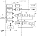
- FIG. 5 is a schematic hardware configuration diagram showing a machining path creating apparatus according to the second embodiment.
- the machining path creating device 1 is mounted on a control device for controlling a machine tool is shown.
- the CPU 311 included in the machining path creating device 1 is a processor that controls the machining path creating device 1 as a whole.
- the CPU 311 reads out the system program stored in the ROM 312 via the bus 322, and controls the entire processing path creating device 1 according to the system program. Temporary calculation data, display data, various data input from the outside, and the like are temporarily stored in the RAM 313.
- the non-volatile memory 314 is composed of, for example, a memory backed up by a battery (not shown), an SSD (Solid State Drive), or the like.
- the non-volatile memory 314 retains its storage state even when the power of the processing path creating device 1 is turned off.
- the non-volatile memory 314 stores data and processing programs read from the external device 372 via the interface 315. Further, the non-volatile memory 314 stores data input via the input device 371, a machining program, data acquired from the machine tool, and the like.
- the data and the processing program stored in the non-volatile memory 314 may be expanded in the RAM 313 at the time of execution / use. Further, various system programs such as a known analysis program are written in the ROM 312 in advance.
- the interface 315 is an interface for connecting the CPU 311 and an external device 372 such as a USB device. From the external device 372 side, for example, a machining program used for controlling a machine tool, each parameter, and the like can be read. Further, the machining program, each parameter, etc. edited in the machining path creating device 1 can be stored in the external storage means via the external device 372.
- the PLC (programmable logic controller) 316 is a sequence program built in the machining path creation device 1 and is attached to a machine tool and peripheral devices of the machine tool (for example, a tool changer, an actuator such as a robot, or a machine tool). A signal is output to the sensor, etc.) via the I / O unit 317 for control. Further, the PLC 316 receives signals from various switches and peripheral devices of the operation panel installed in the main body of the industrial machine, performs necessary signal processing, and then passes the signals to the CPU 311.
- each data read on the memory data obtained as a result of executing a machining program, a system program, etc. are output and displayed via the interface 318.
- the input device 371 composed of a keyboard, a pointing device, and the like passes commands, data, and the like based on operations by the operator to the CPU 11 via the interface 319.
- the axis control circuit 330 for controlling the axis provided in the machine tool receives a command indicating the movement amount of the axis from the CPU 311 and outputs the command of the axis to the servo amplifier 340.
- the servo amplifier 340 drives the servomotor 350 that moves the drive unit included in the machine tool along the axis.
- the shaft servomotor 350 has a built-in position / speed detector, and feeds back the position / speed feedback signal from the position / speed detector to the shaft control circuit 330. As a result, the position / speed feedback control is performed.
- axis control circuit 330 only one axis control circuit 330, one servo amplifier 340, and one servo motor 350 are shown, but in reality, only the number of axes provided in the machine tool to be controlled is shown.
- a circuit 330, a servo amplifier 340, and a servo motor 350 are prepared.
- the spindle control circuit 360 receives a spindle rotation command and outputs a spindle speed signal to the spindle amplifier 361. In response to this spindle speed signal, the spindle amplifier 361 rotates the spindle motor 362 of the machine tool at the commanded rotation speed to drive the tool.
- a position coder 363 is coupled to the spindle motor 362, and the position coder 363 outputs a feedback pulse in synchronization with the rotation of the spindle. The feedback pulse is read by the CPU 311.
- FIG. 6 shows a schematic block diagram of the functions provided in the machining path creating apparatus 1 according to the second embodiment.
- Each function of the machining path creation device 1 according to the present embodiment is obtained by the CPU 311 included in the machining path creation device 1 shown in FIG. 5 executing a system program and controlling the operation of each part of the machining path creation device 1. It will be realized.
- the processing path creating device 1 includes an analysis unit 100, a shape determination unit 110, a smoothing processing unit 120, a user interface unit 130, and a control unit 150. Further, the machining program 200 acquired from the control device 2, the input device 71, the external device 72, etc. is stored in advance in the RAM 13 to the non-volatile memory 14 of the machining path creation device 1.
- the shape determination unit 110, the smoothing processing unit 120, and the user interface unit 130 according to the present embodiment are the same as the functions according to the first embodiment.
- the analysis unit 100 is realized by executing the system program read from the ROM 312 by the CPU 311 and performing arithmetic processing mainly by the CPU 311 using the RAM 313 and the non-volatile memory 314.
- the analysis unit 100 analyzes the block of the operation command of the machine tool 3 from the machining program 200. Then, based on the analysis result, command data for instructing the operation of the servo motor 350 and the spindle motor 362 included in the machine tool 3 is created.
- the command data related to the machining path of the tool is output to the shape determination unit 110. Further, the command data for instructing the operation of the spindle motor 362 and the peripheral device is output to the control unit 150.
- the control unit 150 executes a system program read from the ROM 312 by the CPU 311 and mainly performs arithmetic processing using the RAM 313 and the non-volatile memory 314 by the CPU 311 and a machine tool using the axis control circuit 330, the spindle control circuit 360, and the PLC 316. It is realized by performing the control processing of each part of 3.
- the control unit 150 controls each axis of the machine tool 3 to control the relative movement of the work and the tool based on the machining path obtained by the smoothing processing unit 120. Further, the control unit 150 generates data related to the rotation of the spindle based on, for example, command data for rotating the spindle of the machine tool 3, and outputs the data to the spindle motor 362. Further, the control unit 150 generates a predetermined signal for operating the peripheral device based on the command data for operating the peripheral device of the machine tool 3, for example, and outputs the predetermined signal to the PLC 316.
- the machining path creating device 1 having the above configuration turns on or off the smoothing process at each command point based on the shape at each command point for the machining path commanded by the machining program 200. To judge. Therefore, even if the operator does not embed an ON / OFF command for the smoothing process in the machining program in advance, the ON / OFF of the smoothing process at each command point is automatically determined, and the tool is moved based on the determination result. Control is done.
- Control device 1 Machining path creation device 2
- Control device 3 Machine tool 11,311 CPU 12,312 ROM 13,313 RAM 14,314 Non-volatile memory 15,16,18,19,315,318,319 Interface 316 PLC 317 I / O unit 22,322 Bus 330
- Axis control circuit 340
- Servo amplifier 350
- Servo motor 360
- Spindle control circuit 361
- Spindle amplifier 362
- Spindle motor 363
- Position coder 70,370 Display device 71,371 Input device 72,372
- External device 100
- Analysis unit 110 Shape determination unit 120 Smoothing processing unit 130
- User interface unit 140
- Output unit 150 Control unit 200 Machining program
Abstract
La présente invention concerne un dispositif de création de chemin de traitement (1) qui comprend : une unité d'analyse (100) qui analyse un programme de traitement et crée un chemin de traitement ; une unité de détermination de forme (110) qui détermine l'état MARCHE/ARRÊT d'une fonction de traitement de lissage au niveau de chaque partie dans le chemin de traitement créé par l'unité d'analyse, sur la base de la forme de chaque partie dans le chemin de traitement ; et une unité de traitement de lissage (120) qui, sur la base du résultat de détermination par l'unité de détermination de forme (110), effectue un traitement de lissage au niveau des parties dans le chemin de traitement où la fonction de traitement de lissage est déterminée comme étant sur MARCHE et qui n'effectue pas de traitement de lissage au niveau des parties dans le chemin de traitement où la fonction de traitement de lissage est déterminée comme étant sur ARRÊT.
Priority Applications (4)
| Application Number | Priority Date | Filing Date | Title |
|---|---|---|---|
| DE112021002766.2T DE112021002766T5 (de) | 2020-05-14 | 2021-05-11 | Bearbeitungspfaderstellungsvorrichtung |
| JP2022521926A JP7428793B2 (ja) | 2020-05-14 | 2021-05-11 | 加工経路作成装置 |
| US17/997,926 US20230229138A1 (en) | 2020-05-14 | 2021-05-11 | Machining path creation device |
| CN202180035035.7A CN115605815A (zh) | 2020-05-14 | 2021-05-11 | 加工路径生成装置 |
Applications Claiming Priority (2)
| Application Number | Priority Date | Filing Date | Title |
|---|---|---|---|
| JP2020-084954 | 2020-05-14 | ||
| JP2020084954 | 2020-05-14 |
Publications (1)
| Publication Number | Publication Date |
|---|---|
| WO2021230237A1 true WO2021230237A1 (fr) | 2021-11-18 |
Family
ID=78524397
Family Applications (1)
| Application Number | Title | Priority Date | Filing Date |
|---|---|---|---|
| PCT/JP2021/017878 WO2021230237A1 (fr) | 2020-05-14 | 2021-05-11 | Dispositif de création de chemin de traitement |
Country Status (5)
| Country | Link |
|---|---|
| US (1) | US20230229138A1 (fr) |
| JP (1) | JP7428793B2 (fr) |
| CN (1) | CN115605815A (fr) |
| DE (1) | DE112021002766T5 (fr) |
| WO (1) | WO2021230237A1 (fr) |
Citations (6)
| Publication number | Priority date | Publication date | Assignee | Title |
|---|---|---|---|---|
| JP2009199483A (ja) * | 2008-02-25 | 2009-09-03 | Mitsubishi Heavy Ind Ltd | 数値制御装置 |
| WO2012056554A1 (fr) * | 2010-10-25 | 2012-05-03 | 株式会社牧野フライス製作所 | Procédé de génération de trajet d'outil et dispositif de génération de trajet d'outil |
| JP2015121966A (ja) * | 2013-12-24 | 2015-07-02 | ファナック株式会社 | テーブル形式データによる運転でのスムージング機能を備えた数値制御装置 |
| WO2016067392A1 (fr) * | 2014-10-29 | 2016-05-06 | 株式会社牧野フライス製作所 | Procédé de génération de trajectoire d'outil et machine-outil |
| JP2017156835A (ja) * | 2016-02-29 | 2017-09-07 | ファナック株式会社 | 加工情報に応じて加工条件を変更可能な数値制御装置 |
| JP2018073097A (ja) * | 2016-10-28 | 2018-05-10 | ファナック株式会社 | 工具経路生成装置、工具経路生成方法及び工具経路生成プログラム |
-
2021
- 2021-05-11 JP JP2022521926A patent/JP7428793B2/ja active Active
- 2021-05-11 US US17/997,926 patent/US20230229138A1/en active Pending
- 2021-05-11 WO PCT/JP2021/017878 patent/WO2021230237A1/fr active Application Filing
- 2021-05-11 DE DE112021002766.2T patent/DE112021002766T5/de active Pending
- 2021-05-11 CN CN202180035035.7A patent/CN115605815A/zh active Pending
Patent Citations (6)
| Publication number | Priority date | Publication date | Assignee | Title |
|---|---|---|---|---|
| JP2009199483A (ja) * | 2008-02-25 | 2009-09-03 | Mitsubishi Heavy Ind Ltd | 数値制御装置 |
| WO2012056554A1 (fr) * | 2010-10-25 | 2012-05-03 | 株式会社牧野フライス製作所 | Procédé de génération de trajet d'outil et dispositif de génération de trajet d'outil |
| JP2015121966A (ja) * | 2013-12-24 | 2015-07-02 | ファナック株式会社 | テーブル形式データによる運転でのスムージング機能を備えた数値制御装置 |
| WO2016067392A1 (fr) * | 2014-10-29 | 2016-05-06 | 株式会社牧野フライス製作所 | Procédé de génération de trajectoire d'outil et machine-outil |
| JP2017156835A (ja) * | 2016-02-29 | 2017-09-07 | ファナック株式会社 | 加工情報に応じて加工条件を変更可能な数値制御装置 |
| JP2018073097A (ja) * | 2016-10-28 | 2018-05-10 | ファナック株式会社 | 工具経路生成装置、工具経路生成方法及び工具経路生成プログラム |
Also Published As
| Publication number | Publication date |
|---|---|
| US20230229138A1 (en) | 2023-07-20 |
| DE112021002766T5 (de) | 2023-03-02 |
| JPWO2021230237A1 (fr) | 2021-11-18 |
| JP7428793B2 (ja) | 2024-02-06 |
| CN115605815A (zh) | 2023-01-13 |
Similar Documents
| Publication | Publication Date | Title |
|---|---|---|
| JP4351281B2 (ja) | 5軸加工機を制御する数値制御装置 | |
| US20090228138A1 (en) | Numerical controller controlling five-axis processing machine | |
| US9207668B2 (en) | Method of and apparatus for automated path learning | |
| JP6646027B2 (ja) | ポストプロセッサ装置、加工プログラム生成方法、cnc加工システム及び加工プログラム生成用プログラム | |
| JP6068423B2 (ja) | 加工動作をロボットに教示するロボットプログラミング装置 | |
| JP4233147B2 (ja) | 工作機械用に適応可能なフィードレートを決定する方法 | |
| JP4847428B2 (ja) | 加工シミュレーション装置およびそのプログラム | |
| JP2020071734A (ja) | 数値制御装置 | |
| JP7348013B2 (ja) | シミュレーション装置 | |
| JP2018005480A (ja) | スカイビング加工制御を行う数値制御装置 | |
| JP2019188558A (ja) | 工具選定装置及び機械学習装置 | |
| JP4796936B2 (ja) | 加工制御装置 | |
| JP6321605B2 (ja) | 曲率と曲率変化量による速度制御を行う数値制御装置 | |
| WO2021230237A1 (fr) | Dispositif de création de chemin de traitement | |
| JP6490118B2 (ja) | 数値制御装置 | |
| JP6823032B2 (ja) | プログラム修正装置 | |
| WO2023058243A9 (fr) | Dispositif de commande et programme de stockage de support d'enregistrement lisible par ordinateur | |
| WO2022075223A1 (fr) | Dispositif de commande | |
| WO2022138843A1 (fr) | Dispositif de commande numérique | |
| JP4560191B2 (ja) | 数値制御装置 | |
| JP6110250B2 (ja) | Ncプログラムにおける回転送り軸指令の変化度合いの算出及び表示方法並びに装置 | |
| WO2023026484A1 (fr) | Dispositif de création de programme d'évaluation et support d'enregistrement lisible par ordinateur enregistrant un programme | |
| JP6640822B2 (ja) | 数値制御装置 | |
| WO2022264338A1 (fr) | Dispositif de commande, dispositif de vérification d'interférence et système de commande | |
| WO2021141019A1 (fr) | Dispositif de dessin de trajet de déplacement |
Legal Events
| Date | Code | Title | Description |
|---|---|---|---|
| 121 | Ep: the epo has been informed by wipo that ep was designated in this application |
Ref document number: 21804840 Country of ref document: EP Kind code of ref document: A1 |
|
| ENP | Entry into the national phase |
Ref document number: 2022521926 Country of ref document: JP Kind code of ref document: A |
|
| 122 | Ep: pct application non-entry in european phase |
Ref document number: 21804840 Country of ref document: EP Kind code of ref document: A1 |