WO2021230237A1 - Processing path creation device - Google Patents
Processing path creation device Download PDFInfo
- Publication number
- WO2021230237A1 WO2021230237A1 PCT/JP2021/017878 JP2021017878W WO2021230237A1 WO 2021230237 A1 WO2021230237 A1 WO 2021230237A1 JP 2021017878 W JP2021017878 W JP 2021017878W WO 2021230237 A1 WO2021230237 A1 WO 2021230237A1
- Authority
- WO
- WIPO (PCT)
- Prior art keywords
- processing
- smoothing
- path
- machining
- command
- Prior art date
Links
Images


Classifications
-
- G—PHYSICS
- G05—CONTROLLING; REGULATING
- G05B—CONTROL OR REGULATING SYSTEMS IN GENERAL; FUNCTIONAL ELEMENTS OF SUCH SYSTEMS; MONITORING OR TESTING ARRANGEMENTS FOR SUCH SYSTEMS OR ELEMENTS
- G05B19/00—Programme-control systems
- G05B19/02—Programme-control systems electric
- G05B19/18—Numerical control [NC], i.e. automatically operating machines, in particular machine tools, e.g. in a manufacturing environment, so as to execute positioning, movement or co-ordinated operations by means of programme data in numerical form
- G05B19/41—Numerical control [NC], i.e. automatically operating machines, in particular machine tools, e.g. in a manufacturing environment, so as to execute positioning, movement or co-ordinated operations by means of programme data in numerical form characterised by interpolation, e.g. the computation of intermediate points between programmed end points to define the path to be followed and the rate of travel along that path
- G05B19/4103—Digital interpolation
-
- G—PHYSICS
- G05—CONTROLLING; REGULATING
- G05B—CONTROL OR REGULATING SYSTEMS IN GENERAL; FUNCTIONAL ELEMENTS OF SUCH SYSTEMS; MONITORING OR TESTING ARRANGEMENTS FOR SUCH SYSTEMS OR ELEMENTS
- G05B2219/00—Program-control systems
- G05B2219/30—Nc systems
- G05B2219/34—Director, elements to supervisory
- G05B2219/34127—Brm followed by postprocessor to smooth curve
-
- Y—GENERAL TAGGING OF NEW TECHNOLOGICAL DEVELOPMENTS; GENERAL TAGGING OF CROSS-SECTIONAL TECHNOLOGIES SPANNING OVER SEVERAL SECTIONS OF THE IPC; TECHNICAL SUBJECTS COVERED BY FORMER USPC CROSS-REFERENCE ART COLLECTIONS [XRACs] AND DIGESTS
- Y02—TECHNOLOGIES OR APPLICATIONS FOR MITIGATION OR ADAPTATION AGAINST CLIMATE CHANGE
- Y02P—CLIMATE CHANGE MITIGATION TECHNOLOGIES IN THE PRODUCTION OR PROCESSING OF GOODS
- Y02P90/00—Enabling technologies with a potential contribution to greenhouse gas [GHG] emissions mitigation
- Y02P90/02—Total factory control, e.g. smart factories, flexible manufacturing systems [FMS] or integrated manufacturing systems [IMS]
Definitions
- the present invention relates to a machining path creating device, and more particularly to a machining path creating device having a function of smoothing a machining path instructed by a program.
- a smoothing function is known in which a smoothing process (smoothing process) is performed on a moving path (machining path) of a tool formed by connecting each command point.
- the smoothing function is used, for example, to make the machined surface smooth and of high quality.
- a smoothing point is generated based on a smoothing curve obtained by setting discrete values for each command point for a machining path given by the command point.
- the smoothing processing method include a method using smooth tolerance control, a method using a B-spline curve and a Bezier curve, and a method using a simple average and a weighted average.
- the machining program created by the operator may include a portion where it is desired to machine in a machining path having straight lines or vertices without smoothing the machining surface.
- smoothing is performed on a machining program including such a portion, smoothing is also performed on a portion where processing in a processing path having straight lines or vertices is desired. Therefore, there is a problem that the originally expected processing shape cannot be realized and the processing target becomes defective.
- a command for turning on / off the smoothing process can be added to the machining program. That is, it is possible to prevent the smoothing process from being performed on a part such as a straight line or a vertex where the shape needs to be maintained. However, in this case, it is necessary to add a command to all the parts of the machining program for switching ON / OFF of the smoothing process. As a result, there arises a problem that the burden of creating a machining program for the operator becomes large. Therefore, there is a demand for a technique for automatically determining ON / OFF of the smoothing process based on a predetermined standard.
- the above problem is solved by determining ON / OFF of the smoothing process by using a parameter depending on the shape. More specifically, ON / OFF of the smoothing process is determined by using the parameter related to the curvature.
- the change in the parameter related to the curvature is large in the part where the machining path having a shape such as a straight line or the apex changes suddenly, and the change in the parameter related to the curvature is small before and after that, so this tendency is judged. To reflect.
- one aspect of the present invention is a machining path creating device that creates a machining path that is a movement path of a tool with respect to a work based on a machining program, and an analysis unit that analyzes the machining program to create a machining path.
- the smoothing process is performed on the portion of the machining path determined to turn on the smoothing process function, and the smoothing process is not performed on the portion of the machining path determined to turn off the smoothing process function.
- smoothing can be applied to a workpiece having a complicated shape by specifying a portion of the machining path that changes rapidly by using a parameter depending on the shape. Since the parameter related to the curvature does not depend on the fineness of the command point, it is possible to accurately determine the portion where the machining path changes abruptly.
- FIG. 1 is a schematic hardware configuration diagram showing a machining path creating apparatus according to the first embodiment.
- the machining path creating device 1 can be mounted on a control device that controls an industrial machine that performs machining such as a machine tool. Further, the machining path creating device 1 is mounted on, for example, a personal computer attached to a control device for controlling a machine tool, a personal computer connected to the control device via a wired / wireless network, a fog computer, a cloud server, or the like. be able to. In this embodiment, an example in which the machining path creating device 1 is mounted on a personal computer provided with a control device for controlling a machine tool is shown.
- the CPU 11 included in the machining path creating device 1 is a processor that controls the machining path creating device 1 as a whole.
- the CPU 11 reads out the system program stored in the ROM 12 via the bus 22, and controls the entire processing path creating device 1 according to the system program. Temporary calculation data, display data, various data input from the outside, and the like are temporarily stored in the RAM 13.
- the non-volatile memory 14 is composed of, for example, a memory backed up by a battery (not shown), an SSD (Solid State Drive), or the like.
- the non-volatile memory 14 retains the storage state even when the power of the processing path creating device 1 is turned off.
- the non-volatile memory 14 stores data and processing programs read from the external device 72 via the interface 15. Further, the non-volatile memory 14 stores data and processing programs acquired from the control device 2 via the interface 16. Further, the non-volatile memory 14 stores data, processing programs, and the like input via the input device 71.
- the data and the processing program stored in the non-volatile memory 14 may be expanded in the RAM 13 at the time of execution / use. Further, various system programs such as known processing programs and analysis programs are written in the ROM 12 in advance.
- the interface 15 is an interface for connecting the CPU 11 of the processing path creating device 1 and an external device 72 such as a USB device. From the external device 72 side, for example, a machining program used for controlling a machine tool, various parameters, and the like can be read. Further, the machining program, various parameters, and the like edited in the machining path creating device 1 can be stored in the external storage means via the external device 72.
- each data read into the non-volatile memory 14 data obtained as a result of executing a machining program, a system program, or the like is output and displayed via the interface 18.
- the input device 71 composed of a keyboard, a pointing device, and the like passes commands, data, and the like based on operations by the operator to the CPU 11 via the interface 19.
- FIG. 2 shows a schematic block diagram of the functions provided by the machining path creating apparatus 1 according to the first embodiment.
- Each function of the machining path creating apparatus 1 according to the present embodiment is realized by the CPU 11 executing a system program and controlling the operation of each part of the machining path creating apparatus 1.
- the processing path creating device 1 includes an analysis unit 100, a shape determination unit 110, a smoothing processing unit 120, a user interface unit 130, and an output unit 140. Further, the machining program 200 acquired from the control device 2, the input device 71, the external device 72, etc. is stored in advance in the RAM 13 to the non-volatile memory 14 of the machining path creation device 1.
- the analysis unit 100 is realized by executing the system program read from the ROM 12 by the CPU 11 and performing arithmetic processing mainly by the CPU 11 using the RAM 13 and the non-volatile memory 14.
- the analysis unit 100 analyzes the block of the operation command of the machine tool 3 in the machining program 200. Then, based on the analysis result, a machining path of the tool provided in the machine tool 3 is created.
- the analysis unit 100 outputs the data related to the created processing path to the shape determination unit 110.
- the shape determination unit 110 is realized by executing a system program read from the ROM 12 by the CPU 11 and performing arithmetic processing mainly by the CPU 11 using the RAM 13 and the non-volatile memory 14.
- the shape determination unit 110 determines the shape of each part of the processing path based on the data related to the processing path input from the analysis unit 100. For example, the shape determination unit 110 calculates the curvature at the position of each command point of the processing path, and determines the shape of each part of the processing path based on the curvature.
- a temporary smoothing process is performed on the machining path, and the curvature ⁇ in the vicinity of each command point of the smoothing curve is calculated by the following equation 1 and this is the command. It may be the curvature at the point.
- the method of calculating the curvature is not limited to the equation 1, and other general methods can be appropriately adopted.
- the shape determination unit 110 determines that the smoothing process is turned off (not subject to the smoothing process) at the command point where the curvature is (or exceeds) a predetermined threshold value Th ⁇ or more.
- the shape determination unit 110 may determine that the smoothing process is turned on (targeted for the smoothing process) at a command point whose curvature is less than (or less than or equal to) a predetermined threshold value Th ⁇ .
- the shape determination unit 110 outputs the ON / OFF determination result of the smoothing process at each command point to the smoothing process unit 120.
- FIG. 3 shows an example of a machining path instructed by the machining program 200.
- the command points P i-1 to P i + 5 are commanded by the machining program 200, and the smoothing process is performed by smooth tolerant control.
- the shape determination unit 110 first performs temporary smoothing of the machining path commanded by the command points P i-1 to P i + 5 by smooth tolerant control, and calculates a temporary smoothing curve. Then, the curvature of the temporary smoothing curve in the vicinity of the command points P i-1 to P i + 5 (for example, the curvature at the point closest to the command point among the interpolation points calculated for the smoothing process) is set as the command point.
- a threshold value Th ⁇ that is larger than the curvature at the command point P i or the command point P i + 1 and smaller than the curvature at the command point P i + 2 to the command point P i + 4 is set in advance.
- the shape determination unit 110 determines that the smoothing process is turned off for the processing path that bends at a substantially right angle and the processing path that bends steeper than the substantially right angle.
- the smoothing processing unit 120 is realized by executing a system program read from the ROM 12 by the CPU 11 and performing arithmetic processing mainly by the CPU 11 using the RAM 13 and the non-volatile memory 14.
- the smoothing processing unit 120 performs smoothing processing of the processing path based on the ON / OFF determination result of the smoothing processing at each command point input from the shape determination unit 110.
- the smoothing processing unit 120 performs smoothing processing at a command point determined by the shape determination unit 110 to turn on the smoothing processing. Further, the smoothing processing unit 120 does not perform the smoothing processing at the command point where the shape determination unit 110 determines that the smoothing processing is turned off, and does not change the processing path.
- the machining path created by the smoothing processing unit 120 is output to the user interface unit 130.
- FIG. 4 sets a threshold value Th ⁇ that is larger than the curvature at the command point P i and the command point P i + 1 and smaller than the curvature at the command point P i + 2 to the command point P i + 4 in the example of FIG. It is a figure which shows the result of the smoothing processing by the smoothing processing unit 120 in the case of. As illustrated in FIG. 4, smoothing processing is executed at the command point P i and the command point P i + 1 based on the judgment by the shape determination unit 110, and the command point P i + 2 to the command point P i + In 4 , the smoothing process is not executed and the original machining path is output.
- the user interface unit 130 is realized by executing a system program read from the ROM 12 by the CPU 11 and mainly performing arithmetic processing using the RAM 13 and the non-volatile memory 14 by the CPU 11 and output processing using the interface 18. ..
- the user interface unit 130 displays on the display device 70 the processing path smoothed by the smoothing processing unit 120 according to the determination result of the shape determination unit 110.
- the user interface unit 130 may display the command point determined to be ON for the smoothing process and the command point determined to be OFF for the smoothing process to be distinguishable on the smoothed processing path. Further, the user interface unit 130 may receive an input from the operator for correcting ON / OFF of the smoothing process at each command point.
- the user interface unit 130 may instruct the smoothing processing unit 120 to perform the smoothing process again in consideration of the ON / OFF correction of the smoothing process for each command point from the operator.
- the user interface unit 130 may receive a command from the operator to output the processing path smoothed by the smoothing processing unit 120 to the output unit 140.
- the output unit 140 is realized by executing the system program read from the ROM 12 by the CPU 11 and performing arithmetic processing mainly by the CPU 11 using the RAM 13 and the non-volatile memory 14 and output processing using the interface 18. NS.
- the output unit 140 outputs the processing path smoothed by the smoothing processing unit 120 to the control device 2.
- the output unit 140 may output to the control device 2 a block including a command for moving the tool along the smoothed machining path, which is replaced with a predetermined block of the machining program 200.
- the machining path creating device 1 having the above configuration turns on or off the smoothing process at each command point based on the shape at each command point for the machining path commanded by the machining program 200. To judge. Therefore, even if the operator does not embed an ON / OFF command for the smoothing process in the machining program in advance, the ON / OFF of the smoothing process at each command point is automatically determined. The operator can confirm the machining path created as a result of the automatic determination and correct ON / OFF of the smoothing process at some command points as necessary. Further, the modified machining path can be output to the control device 2 for machining. Therefore, the labor involved in creating the machining program of the operator is reduced.
- the shape determination unit 110 may determine the shape of each portion of the machining path based on, for example, a change in curvature at the position of each command point.
- the change in curvature at the position of each command point on the machining path may be determined by using, for example, the amount of change in curvature ⁇ calculated by the following equation (2).
- R i (i is a positive integer) is the radius of curvature at the position of each command point P i (i is a positive integer, the first command point is P 0) in the machining path.
- a temporary smoothing process is performed on the machining path, and the radius of curvature R in the vicinity of each command point of the smoothing curve is calculated by the following equation 3 to calculate the command point. It may be the radius of curvature in.
- the Rs i in Equation 2 S j-1 in the example of the interpolation points ( Figure 3 immediately before the interpolation point for smoothing processing to be located in the vicinity of the command points P i (S j in the example of FIG. 3) ) Is the radius of curvature.
- the shape determination unit 110 turns off the smoothing process at the command point where the curvature change amount is (or exceeds) a predetermined threshold value Th ⁇ (not subject to the smoothing process). Is determined.
- the shape determination unit 110 may determine that the smoothing process is turned on (targeted for the smoothing process) at a command point whose curvature is less than (or less than or equal to) a predetermined threshold value Th ⁇ .
- the change in curvature at the position of each command point on the machining path may be determined by using, for example, the curvature change rate ⁇ calculated by the following equation (4).
- the shape determination unit 110 turns off the smoothing process at the command point where the curvature change rate is separated from (or exceeds) a predetermined threshold value Th ⁇ (target of smoothing process). Do not).
- the shape determination unit 110 determines that the smoothing process is turned on (targeted for the smoothing process) at a command point whose curvature change rate is within (or within) a predetermined threshold value Th ⁇ from 1. Just do it.
- the method for calculating the change in curvature is not limited to the above-mentioned method for obtaining the amount of change in curvature and the rate of change in curvature, and other general methods can be appropriately adopted.
- the machining path creating device 1 determines whether to turn on or off the smoothing process at each command point based on the change in curvature at each command point for the machining path commanded by the machining program 200.
- the value indicating the change in curvature takes a large value in the portion where the machining path changes from a gentle bend to a sharp bend, and in the portion where the sharp bend changes to a gentle bend. Therefore, in general, the smoothing process is turned off in the portion where the operator intends to make a sharp change, that is, the portion intended to be machined at an acute angle, and the smoothing process tends to be turned on in the other portions. Therefore, it is possible to control the smoothing process that more reflects the intention of the operator.
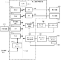
- FIG. 5 is a schematic hardware configuration diagram showing a machining path creating apparatus according to the second embodiment.
- the machining path creating device 1 is mounted on a control device for controlling a machine tool is shown.
- the CPU 311 included in the machining path creating device 1 is a processor that controls the machining path creating device 1 as a whole.
- the CPU 311 reads out the system program stored in the ROM 312 via the bus 322, and controls the entire processing path creating device 1 according to the system program. Temporary calculation data, display data, various data input from the outside, and the like are temporarily stored in the RAM 313.
- the non-volatile memory 314 is composed of, for example, a memory backed up by a battery (not shown), an SSD (Solid State Drive), or the like.
- the non-volatile memory 314 retains its storage state even when the power of the processing path creating device 1 is turned off.
- the non-volatile memory 314 stores data and processing programs read from the external device 372 via the interface 315. Further, the non-volatile memory 314 stores data input via the input device 371, a machining program, data acquired from the machine tool, and the like.
- the data and the processing program stored in the non-volatile memory 314 may be expanded in the RAM 313 at the time of execution / use. Further, various system programs such as a known analysis program are written in the ROM 312 in advance.
- the interface 315 is an interface for connecting the CPU 311 and an external device 372 such as a USB device. From the external device 372 side, for example, a machining program used for controlling a machine tool, each parameter, and the like can be read. Further, the machining program, each parameter, etc. edited in the machining path creating device 1 can be stored in the external storage means via the external device 372.
- the PLC (programmable logic controller) 316 is a sequence program built in the machining path creation device 1 and is attached to a machine tool and peripheral devices of the machine tool (for example, a tool changer, an actuator such as a robot, or a machine tool). A signal is output to the sensor, etc.) via the I / O unit 317 for control. Further, the PLC 316 receives signals from various switches and peripheral devices of the operation panel installed in the main body of the industrial machine, performs necessary signal processing, and then passes the signals to the CPU 311.
- each data read on the memory data obtained as a result of executing a machining program, a system program, etc. are output and displayed via the interface 318.
- the input device 371 composed of a keyboard, a pointing device, and the like passes commands, data, and the like based on operations by the operator to the CPU 11 via the interface 319.
- the axis control circuit 330 for controlling the axis provided in the machine tool receives a command indicating the movement amount of the axis from the CPU 311 and outputs the command of the axis to the servo amplifier 340.
- the servo amplifier 340 drives the servomotor 350 that moves the drive unit included in the machine tool along the axis.
- the shaft servomotor 350 has a built-in position / speed detector, and feeds back the position / speed feedback signal from the position / speed detector to the shaft control circuit 330. As a result, the position / speed feedback control is performed.
- axis control circuit 330 only one axis control circuit 330, one servo amplifier 340, and one servo motor 350 are shown, but in reality, only the number of axes provided in the machine tool to be controlled is shown.
- a circuit 330, a servo amplifier 340, and a servo motor 350 are prepared.
- the spindle control circuit 360 receives a spindle rotation command and outputs a spindle speed signal to the spindle amplifier 361. In response to this spindle speed signal, the spindle amplifier 361 rotates the spindle motor 362 of the machine tool at the commanded rotation speed to drive the tool.
- a position coder 363 is coupled to the spindle motor 362, and the position coder 363 outputs a feedback pulse in synchronization with the rotation of the spindle. The feedback pulse is read by the CPU 311.
- FIG. 6 shows a schematic block diagram of the functions provided in the machining path creating apparatus 1 according to the second embodiment.
- Each function of the machining path creation device 1 according to the present embodiment is obtained by the CPU 311 included in the machining path creation device 1 shown in FIG. 5 executing a system program and controlling the operation of each part of the machining path creation device 1. It will be realized.
- the processing path creating device 1 includes an analysis unit 100, a shape determination unit 110, a smoothing processing unit 120, a user interface unit 130, and a control unit 150. Further, the machining program 200 acquired from the control device 2, the input device 71, the external device 72, etc. is stored in advance in the RAM 13 to the non-volatile memory 14 of the machining path creation device 1.
- the shape determination unit 110, the smoothing processing unit 120, and the user interface unit 130 according to the present embodiment are the same as the functions according to the first embodiment.
- the analysis unit 100 is realized by executing the system program read from the ROM 312 by the CPU 311 and performing arithmetic processing mainly by the CPU 311 using the RAM 313 and the non-volatile memory 314.
- the analysis unit 100 analyzes the block of the operation command of the machine tool 3 from the machining program 200. Then, based on the analysis result, command data for instructing the operation of the servo motor 350 and the spindle motor 362 included in the machine tool 3 is created.
- the command data related to the machining path of the tool is output to the shape determination unit 110. Further, the command data for instructing the operation of the spindle motor 362 and the peripheral device is output to the control unit 150.
- the control unit 150 executes a system program read from the ROM 312 by the CPU 311 and mainly performs arithmetic processing using the RAM 313 and the non-volatile memory 314 by the CPU 311 and a machine tool using the axis control circuit 330, the spindle control circuit 360, and the PLC 316. It is realized by performing the control processing of each part of 3.
- the control unit 150 controls each axis of the machine tool 3 to control the relative movement of the work and the tool based on the machining path obtained by the smoothing processing unit 120. Further, the control unit 150 generates data related to the rotation of the spindle based on, for example, command data for rotating the spindle of the machine tool 3, and outputs the data to the spindle motor 362. Further, the control unit 150 generates a predetermined signal for operating the peripheral device based on the command data for operating the peripheral device of the machine tool 3, for example, and outputs the predetermined signal to the PLC 316.
- the machining path creating device 1 having the above configuration turns on or off the smoothing process at each command point based on the shape at each command point for the machining path commanded by the machining program 200. To judge. Therefore, even if the operator does not embed an ON / OFF command for the smoothing process in the machining program in advance, the ON / OFF of the smoothing process at each command point is automatically determined, and the tool is moved based on the determination result. Control is done.
- Control device 1 Machining path creation device 2
- Control device 3 Machine tool 11,311 CPU 12,312 ROM 13,313 RAM 14,314 Non-volatile memory 15,16,18,19,315,318,319 Interface 316 PLC 317 I / O unit 22,322 Bus 330
- Axis control circuit 340
- Servo amplifier 350
- Servo motor 360
- Spindle control circuit 361
- Spindle amplifier 362
- Spindle motor 363
- Position coder 70,370 Display device 71,371 Input device 72,372
- External device 100
- Analysis unit 110 Shape determination unit 120 Smoothing processing unit 130
- User interface unit 140
- Output unit 150 Control unit 200 Machining program
Abstract
A processing path creation device 1 includes: an analysis unit 100 that analyzes a processing program and creates a processing path; a shape determination unit 110 that determines the ON/OFF state of a smoothing processing function at each portion in the processing path created by the analysis unit, on the basis of the shape of each portion in the processing path; and a smoothing processing unit 120 that, on the basis of the determination result by the shape determination unit 110, performs smoothing processing at portions in the processing path where the smoothing processing function is determined to be turned ON, and that does not perform smoothing processing at portions in the processing path where the smoothing processing function is determined to be turned OFF.
Description
本発明は、加工経路作成装置に関し、特にプログラムで指令された加工経路をスムージングする機能を備えた加工経路作成装置に関する。
The present invention relates to a machining path creating device, and more particularly to a machining path creating device having a function of smoothing a machining path instructed by a program.
工作機械で加工を行う場合、加工プログラムにおいてワークに対する工具の相対的位置を表す複数の指令点を指令する。制御装置は、加工プログラムを実行し、各指令点を通るようにワークに対して工具を相対的に移動させることでワークを加工する。各指令点を連結して形成される工具の移動経路(加工経路)に平滑化処理(スムージング処理)を施すスムージング機能が知られている。スムージング機能は、例えば加工面を滑らかで高品位なものとするために用いられる。
When machining with a machine tool, multiple command points indicating the relative position of the tool with respect to the workpiece are commanded in the machining program. The control device executes a machining program and machining the workpiece by moving the tool relative to the workpiece so as to pass through each command point. A smoothing function is known in which a smoothing process (smoothing process) is performed on a moving path (machining path) of a tool formed by connecting each command point. The smoothing function is used, for example, to make the machined surface smooth and of high quality.
一般に、スムージング処理では、指令点によって与えられた加工経路に対して、指令点毎に離散的な値を設定して得られるスムージング曲線をもとに、スムージング点を生成する。生成されたスムージング点を通るスムージング経路を設定することで、加工面が滑らかになるよう加工経路の最適化が行われる。スムージング処理の手法には、スムーズトレランス制御による手法や、B-スプライン曲線やベジェ曲線を用いる手法、単純平均や加重平均を用いる手法等がある。
Generally, in the smoothing process, a smoothing point is generated based on a smoothing curve obtained by setting discrete values for each command point for a machining path given by the command point. By setting a smoothing path that passes through the generated smoothing point, the machining path is optimized so that the machining surface becomes smooth. Examples of the smoothing processing method include a method using smooth tolerance control, a method using a B-spline curve and a Bezier curve, and a method using a simple average and a weighted average.
スムージング処理では、加工経路が同じ場合であっても指令点の数や点列(各指令点の間隔)のパターンが異なることで、処理の結果として得られるスムージング経路の形状に違いが生じる。
このような問題に対処する技術として、指令点の間を一定間隔で分割し、その分割点を指令点とみなしてスムージング処理をする技術が公知となっている(例えば、特許文献1等)。 In the smoothing process, even if the machining path is the same, the number of command points and the pattern of the point sequence (interval between the command points) are different, so that the shape of the smoothing path obtained as a result of the process is different.
As a technique for dealing with such a problem, a technique for dividing between command points at regular intervals and performing smoothing processing by regarding the division points as command points is known (for example,Patent Document 1 and the like).
このような問題に対処する技術として、指令点の間を一定間隔で分割し、その分割点を指令点とみなしてスムージング処理をする技術が公知となっている(例えば、特許文献1等)。 In the smoothing process, even if the machining path is the same, the number of command points and the pattern of the point sequence (interval between the command points) are different, so that the shape of the smoothing path obtained as a result of the process is different.
As a technique for dealing with such a problem, a technique for dividing between command points at regular intervals and performing smoothing processing by regarding the division points as command points is known (for example,
しかしながら、オペレータが作成する加工プログラムには、加工面を滑らかにすることなく、直線や頂点を有する加工経路で加工することが望まれる箇所が含まれることもある。このような箇所を含む加工プログラムに対してスムージング処理を行うと、直線や頂点を有する加工経路での加工が望まれる箇所に対してもスムージングが行われてしまう。そのため、本来想定していた加工形状を実現できず、加工対象が不良になるといった課題がある。
However, the machining program created by the operator may include a portion where it is desired to machine in a machining path having straight lines or vertices without smoothing the machining surface. When smoothing is performed on a machining program including such a portion, smoothing is also performed on a portion where processing in a processing path having straight lines or vertices is desired. Therefore, there is a problem that the originally expected processing shape cannot be realized and the processing target becomes defective.
このような課題に対して、例えば直線や頂点を表したい部分に対して、直線を細かく分割するように、あるいは、頂点を形成する線分を細かく分割するように多くの分割点を設けて対処することもできる。しかし、どれだけ多くの分割点を設けたとしても微小な曲線で構成される補間となる。そのため、望まれる精度を維持することはできない。また、分割点の増加に伴うスムージング処理の負荷の増大が別の問題として生じてしまう。
To deal with such problems, for example, for a straight line or a part where a vertex is to be represented, a large number of dividing points are provided so as to divide the straight line into small pieces or to divide the line segments forming the vertices into small pieces. You can also do it. However, no matter how many division points are provided, the interpolation is composed of minute curves. Therefore, the desired accuracy cannot be maintained. In addition, an increase in the load of the smoothing process due to an increase in the number of division points occurs as another problem.
他の対処法として、加工プログラムにスムージング処理のON/OFFを行う指令を追記することができる。つまり、直線や頂点といった形状の維持が必要な部分では、スムージング処理を行わないようにすることができる。しかしながら、この場合は加工プログラムに対して、スムージング処理のON/OFFの切り替えを行うすべての部分に指令の追記を行う必要がある。その結果、オペレータの加工プログラムの作成の負担が大きくなるという問題が生じる。
そこで、所定の基準に基づいてスムージング処理のON/OFFを自動的に判定する技術が望まれている。 As another countermeasure, a command for turning on / off the smoothing process can be added to the machining program. That is, it is possible to prevent the smoothing process from being performed on a part such as a straight line or a vertex where the shape needs to be maintained. However, in this case, it is necessary to add a command to all the parts of the machining program for switching ON / OFF of the smoothing process. As a result, there arises a problem that the burden of creating a machining program for the operator becomes large.
Therefore, there is a demand for a technique for automatically determining ON / OFF of the smoothing process based on a predetermined standard.
本発明の一態様では、スムージング処理のON/OFFの判定を形状に依存するパラメータを用いて行うことで、上記課題を解決する。
より具体的には、曲率に係るパラメータを用いることで、スムージング処理のON/OFFの判定を行う。一般に、直線や頂点といった形状を有するような加工経路が急激に変化する部分では曲率に係るパラメータの変化が大きく、その前後では曲率に係るパラメータの変化が小さい場合が多いので、この傾向を判定に反映させる。 In one aspect of the present invention, the above problem is solved by determining ON / OFF of the smoothing process by using a parameter depending on the shape.
More specifically, ON / OFF of the smoothing process is determined by using the parameter related to the curvature. In general, the change in the parameter related to the curvature is large in the part where the machining path having a shape such as a straight line or the apex changes suddenly, and the change in the parameter related to the curvature is small before and after that, so this tendency is judged. To reflect.
そして、本発明の一態様は、加工プログラムに基づいてワークに対する工具の移動経路である加工経路を作成する加工経路作成装置であって、前記加工プログラムを解析して加工経路を作成する解析部と、前記解析部が作成した加工経路における各部分の形状に基づいて、前記加工経路における各部分におけるスムージング処理の機能のON/OFFを判定する形状判定部と、前記形状判定部による判定結果に基づいて、前記加工経路の内でスムージング処理の機能をONとすると判定された部分についてスムージング処理を行い、前記加工経路の内でスムージング処理の機能をOFFとすると判定された部分についてスムージング処理を行わないスムージング処理部と、を備えた加工経路作成装置である。
Then, one aspect of the present invention is a machining path creating device that creates a machining path that is a movement path of a tool with respect to a work based on a machining program, and an analysis unit that analyzes the machining program to create a machining path. Based on the shape determination unit that determines ON / OFF of the smoothing processing function in each part of the processing path based on the shape of each part in the processing path created by the analysis unit, and the determination result by the shape determination unit. Therefore, the smoothing process is performed on the portion of the machining path determined to turn on the smoothing process function, and the smoothing process is not performed on the portion of the machining path determined to turn off the smoothing process function. It is a processing path creating device provided with a smoothing processing unit.
本発明の一態様により、加工経路の急激に変化する部分を、形状に依存するパラメータを用いて特定することにより、複雑な形状の加工物にもスムージングを適用することができる。曲率に係るパラメータは指令点の細かさに依存しないため、加工経路が急激に変化する部分の判定を精度よく行うことができる。
According to one aspect of the present invention, smoothing can be applied to a workpiece having a complicated shape by specifying a portion of the machining path that changes rapidly by using a parameter depending on the shape. Since the parameter related to the curvature does not depend on the fineness of the command point, it is possible to accurately determine the portion where the machining path changes abruptly.
以下、本発明の実施形態を図面と共に説明する。
図1は第1実施形態による加工経路作成装置を示す概略的なハードウェア構成図である。加工経路作成装置1は、例えば工作機械等の加工を行う産業機械を制御する制御装置に実装することができる。また、加工経路作成装置1は、例えば工作機械を制御する制御装置に併設されたパソコンや、該制御装置と有線/無線のネットワークを介して接続されたパソコン、フォグコンピュータ、クラウドサーバ等に実装することができる。本実施形態では、加工経路作成装置1を、工作機械を制御する制御装置と併設したパソコンに実装した例を示す。 Hereinafter, embodiments of the present invention will be described with reference to the drawings.
FIG. 1 is a schematic hardware configuration diagram showing a machining path creating apparatus according to the first embodiment. The machiningpath creating device 1 can be mounted on a control device that controls an industrial machine that performs machining such as a machine tool. Further, the machining path creating device 1 is mounted on, for example, a personal computer attached to a control device for controlling a machine tool, a personal computer connected to the control device via a wired / wireless network, a fog computer, a cloud server, or the like. be able to. In this embodiment, an example in which the machining path creating device 1 is mounted on a personal computer provided with a control device for controlling a machine tool is shown.
図1は第1実施形態による加工経路作成装置を示す概略的なハードウェア構成図である。加工経路作成装置1は、例えば工作機械等の加工を行う産業機械を制御する制御装置に実装することができる。また、加工経路作成装置1は、例えば工作機械を制御する制御装置に併設されたパソコンや、該制御装置と有線/無線のネットワークを介して接続されたパソコン、フォグコンピュータ、クラウドサーバ等に実装することができる。本実施形態では、加工経路作成装置1を、工作機械を制御する制御装置と併設したパソコンに実装した例を示す。 Hereinafter, embodiments of the present invention will be described with reference to the drawings.
FIG. 1 is a schematic hardware configuration diagram showing a machining path creating apparatus according to the first embodiment. The machining
加工経路作成装置1が備えるCPU11は、加工経路作成装置1を全体的に制御するプロセッサである。CPU11は、バス22を介してROM12に格納されたシステム・プログラムを読み出し、該システム・プログラムに従って加工経路作成装置1全体を制御する。RAM13には一時的な計算データや表示データ、及び外部から入力された各種データ等が一時的に格納される。
The CPU 11 included in the machining path creating device 1 is a processor that controls the machining path creating device 1 as a whole. The CPU 11 reads out the system program stored in the ROM 12 via the bus 22, and controls the entire processing path creating device 1 according to the system program. Temporary calculation data, display data, various data input from the outside, and the like are temporarily stored in the RAM 13.
不揮発性メモリ14は、例えば図示しないバッテリでバックアップされたメモリやSSD(Solid State Drive)等で構成される。不揮発性メモリ14は、加工経路作成装置1の電源がオフされても記憶状態を保持する。不揮発性メモリ14には、インタフェース15を介して外部機器72から読み込まれたデータや加工プログラムが記憶される。また、不揮発性メモリ14には、インタフェース16を介して制御装置2から取得したデータや加工プログラムが記憶される。また、不揮発性メモリ14には、入力装置71を介して入力されたデータや加工プログラム等が記憶される。不揮発性メモリ14に記憶されたデータや加工プログラムは、実行時/利用時にはRAM13に展開されても良い。また、ROM12には、公知の処理プログラムや解析プログラム等の各種システム・プログラムがあらかじめ書き込まれている。
The non-volatile memory 14 is composed of, for example, a memory backed up by a battery (not shown), an SSD (Solid State Drive), or the like. The non-volatile memory 14 retains the storage state even when the power of the processing path creating device 1 is turned off. The non-volatile memory 14 stores data and processing programs read from the external device 72 via the interface 15. Further, the non-volatile memory 14 stores data and processing programs acquired from the control device 2 via the interface 16. Further, the non-volatile memory 14 stores data, processing programs, and the like input via the input device 71. The data and the processing program stored in the non-volatile memory 14 may be expanded in the RAM 13 at the time of execution / use. Further, various system programs such as known processing programs and analysis programs are written in the ROM 12 in advance.
インタフェース15は、加工経路作成装置1のCPU11とUSB装置等の外部機器72と接続するためのインタフェースである。外部機器72側からは、例えば工作機械の制御に用いられる加工プログラムや各種パラメータ等を読み込むことができる。また、加工経路作成装置1内で編集した加工プログラムや各種パラメータ等は、外部機器72を介して外部記憶手段に記憶させることができる。
The interface 15 is an interface for connecting the CPU 11 of the processing path creating device 1 and an external device 72 such as a USB device. From the external device 72 side, for example, a machining program used for controlling a machine tool, various parameters, and the like can be read. Further, the machining program, various parameters, and the like edited in the machining path creating device 1 can be stored in the external storage means via the external device 72.
表示装置70には、例えば、不揮発性メモリ14に読み込まれた各データ、加工プログラムやシステム・プログラム等が実行された結果として得られたデータ等がインタフェース18を介して出力されて表示される。また、キーボードやポインティングデバイス等から構成される入力装置71は、インタフェース19を介して作業者による操作に基づく指令、データ等をCPU11に渡す。
On the display device 70, for example, each data read into the non-volatile memory 14, data obtained as a result of executing a machining program, a system program, or the like is output and displayed via the interface 18. Further, the input device 71 composed of a keyboard, a pointing device, and the like passes commands, data, and the like based on operations by the operator to the CPU 11 via the interface 19.
図2は、第1実施形態による加工経路作成装置1が備える機能を概略的なブロック図として示したものである。本実施形態による加工経路作成装置1が備える各機能は、CPU11がシステム・プログラムを実行し、加工経路作成装置1の各部の動作を制御することにより実現される。
FIG. 2 shows a schematic block diagram of the functions provided by the machining path creating apparatus 1 according to the first embodiment. Each function of the machining path creating apparatus 1 according to the present embodiment is realized by the CPU 11 executing a system program and controlling the operation of each part of the machining path creating apparatus 1.
加工経路作成装置1は、解析部100、形状判定部110、スムージング処理部120、ユーザインタフェース部130、出力部140を備える。また、加工経路作成装置1のRAM13乃至不揮発性メモリ14には、制御装置2、入力装置71、外部機器72等から取得した加工プログラム200が予め記憶される。
The processing path creating device 1 includes an analysis unit 100, a shape determination unit 110, a smoothing processing unit 120, a user interface unit 130, and an output unit 140. Further, the machining program 200 acquired from the control device 2, the input device 71, the external device 72, etc. is stored in advance in the RAM 13 to the non-volatile memory 14 of the machining path creation device 1.
解析部100は、CPU11がROM12から読み出したシステム・プログラムを実行し、主としてCPU11によるRAM13、不揮発性メモリ14を用いた演算処理が行われることで実現される。解析部100は、加工プログラム200における工作機械3の動作指令のブロックを解析する。そして、その解析結果に基づいて工作機械3が備える工具の加工経路を作成する。解析部100は、作成した加工経路に係るデータを、形状判定部110へ出力する。
The analysis unit 100 is realized by executing the system program read from the ROM 12 by the CPU 11 and performing arithmetic processing mainly by the CPU 11 using the RAM 13 and the non-volatile memory 14. The analysis unit 100 analyzes the block of the operation command of the machine tool 3 in the machining program 200. Then, based on the analysis result, a machining path of the tool provided in the machine tool 3 is created. The analysis unit 100 outputs the data related to the created processing path to the shape determination unit 110.
形状判定部110は、CPU11がROM12から読み出したシステム・プログラムを実行し、主としてCPU11によるRAM13、不揮発性メモリ14を用いた演算処理が行われることで実現される。形状判定部110は、解析部100から入力された加工経路に係るデータに基づいて、該加工経路の各部の形状を判定する。例えば、形状判定部110は、加工経路の各指令点の位置における曲率を算出し、その曲率に基づいて加工経路の各部の形状を判定する。加工経路の各指令点の位置における曲率は、例えば加工経路に対して仮のスムージング処理を行い、そのスムージング曲線の各指令点近傍における曲率κを以下の数1式により算出し、これを当該指令点における曲率とすればよい。なお、数1式においてf’(a)、f”(a)は加工経路を仮スムージング処理して得られたスムージング曲線を表す関数をy=f(x)とした時のx=aの位置における微分値及び二階微分値である。なお、曲率の算出方法は数1式に限定されるものではなく、他の一般的な手法を適宜採用することができる。
The shape determination unit 110 is realized by executing a system program read from the ROM 12 by the CPU 11 and performing arithmetic processing mainly by the CPU 11 using the RAM 13 and the non-volatile memory 14. The shape determination unit 110 determines the shape of each part of the processing path based on the data related to the processing path input from the analysis unit 100. For example, the shape determination unit 110 calculates the curvature at the position of each command point of the processing path, and determines the shape of each part of the processing path based on the curvature. For the curvature at the position of each command point of the machining path, for example, a temporary smoothing process is performed on the machining path, and the curvature κ in the vicinity of each command point of the smoothing curve is calculated by the following equation 1 and this is the command. It may be the curvature at the point. In addition, in the equation 1, f'(a) and f "(a) are the positions of x = a when the function representing the smoothing curve obtained by provisionally smoothing the machining path is y = f (x). The method of calculating the curvature is not limited to the equation 1, and other general methods can be appropriately adopted.

形状判定部110は、曲率が予め定めた閾値Thκ以上(又は超える)となる指令点については、スムージング処理をOFFにする(スムージング処理の対象としない)と判定する。形状判定部110は、曲率が予め定めた閾値Thκ未満(又は以下)となる指令点について、スムージング処理をONにする(スムージング処理の対象とする)と判定するようにしても良い。形状判定部110は、各指令点におけるスムージング処理のON/OFFの判定結果をスムージング処理部120へ出力する。
The shape determination unit 110 determines that the smoothing process is turned off (not subject to the smoothing process) at the command point where the curvature is (or exceeds) a predetermined threshold value Th κ or more. The shape determination unit 110 may determine that the smoothing process is turned on (targeted for the smoothing process) at a command point whose curvature is less than (or less than or equal to) a predetermined threshold value Th κ. The shape determination unit 110 outputs the ON / OFF determination result of the smoothing process at each command point to the smoothing process unit 120.
図3は、加工プログラム200により指令される加工経路の例を示している。図3の例では、加工プログラム200により指令点Pi-1~Pi+5が指令されており、スムージング処理はスムーズトレラント制御により行われているものとする。この時、形状判定部110は、まず指令点Pi-1~Pi+5により指令される加工経路をスムーズトレラント制御による仮スムージングを行い、仮スムージング曲線を算出する。そして、指令点Pi-1~Pi+5の近傍における仮スムージング曲線の曲率(例えば、スムージング処理のために算出された補間点の内で指令点に最も近い点における曲率)を該指令点の曲率として算出する。例えば指令点Piや指令点Pi+1における曲率よりも大きく、指令点Pi+2~指令点Pi+4における曲率よりも小さい閾値Thκが予め設定される。この場合、形状判定部110は、略直角に曲がる加工経路、および略直角よりも急峻に曲がる加工経路についてはスムージング処理をOFFにすると判定する。
FIG. 3 shows an example of a machining path instructed by the machining program 200. In the example of FIG. 3, it is assumed that the command points P i-1 to P i + 5 are commanded by the machining program 200, and the smoothing process is performed by smooth tolerant control. At this time, the shape determination unit 110 first performs temporary smoothing of the machining path commanded by the command points P i-1 to P i + 5 by smooth tolerant control, and calculates a temporary smoothing curve. Then, the curvature of the temporary smoothing curve in the vicinity of the command points P i-1 to P i + 5 (for example, the curvature at the point closest to the command point among the interpolation points calculated for the smoothing process) is set as the command point. Calculated as the curvature of. For example, a threshold value Th κ that is larger than the curvature at the command point P i or the command point P i + 1 and smaller than the curvature at the command point P i + 2 to the command point P i + 4 is set in advance. In this case, the shape determination unit 110 determines that the smoothing process is turned off for the processing path that bends at a substantially right angle and the processing path that bends steeper than the substantially right angle.
スムージング処理部120は、CPU11がROM12から読み出したシステム・プログラムを実行し、主としてCPU11によるRAM13、不揮発性メモリ14を用いた演算処理が行われることで実現される。スムージング処理部120は、形状判定部110から入力された各指令点におけるスムージング処理のON/OFFの判定結果に基づいて、加工経路のスムージング処理を行う。スムージング処理部120は、形状判定部110がスムージング処理をONにすると判定した指令点ではスムージング処理を行う。また、スムージング処理部120は、形状判定部110がスムージング処理をOFFにすると判定した指令点ではスムージング処理を行わず、加工経路を変更しない。スムージング処理部120が作成した加工経路は、ユーザインタフェース部130へと出力される。
The smoothing processing unit 120 is realized by executing a system program read from the ROM 12 by the CPU 11 and performing arithmetic processing mainly by the CPU 11 using the RAM 13 and the non-volatile memory 14. The smoothing processing unit 120 performs smoothing processing of the processing path based on the ON / OFF determination result of the smoothing processing at each command point input from the shape determination unit 110. The smoothing processing unit 120 performs smoothing processing at a command point determined by the shape determination unit 110 to turn on the smoothing processing. Further, the smoothing processing unit 120 does not perform the smoothing processing at the command point where the shape determination unit 110 determines that the smoothing processing is turned off, and does not change the processing path. The machining path created by the smoothing processing unit 120 is output to the user interface unit 130.
図4は、図3の例において、指令点Piや指令点Pi+1における曲率よりも大きく、指令点Pi+2~指令点Pi+4における曲率よりも小さい閾値Thκを設定した場合の、スムージング処理部120によるスムージング処理の結果を示す図である。図4に例示されるように、形状判定部110による判定に基づいて、指令点Piや指令点Pi+1においてはスムージング処理が実行され、指令点Pi+2~指令点Pi+4においてはスムージング処理は実行されずに本来の加工経路が出力される。
FIG. 4 sets a threshold value Th κ that is larger than the curvature at the command point P i and the command point P i + 1 and smaller than the curvature at the command point P i + 2 to the command point P i + 4 in the example of FIG. It is a figure which shows the result of the smoothing processing by the smoothing processing unit 120 in the case of. As illustrated in FIG. 4, smoothing processing is executed at the command point P i and the command point P i + 1 based on the judgment by the shape determination unit 110, and the command point P i + 2 to the command point P i + In 4 , the smoothing process is not executed and the original machining path is output.
ユーザインタフェース部130は、CPU11がROM12から読み出したシステム・プログラムを実行し、主としてCPU11によるRAM13、不揮発性メモリ14を用いた演算処理と、インタフェース18を用いた出力処理が行われることで実現される。ユーザインタフェース部130は、スムージング処理部120が形状判定部110の判定結果に従ってスムージング処理した加工経路を表示装置70に表示する。ユーザインタフェース部130は、例えばスムージング処理した加工経路に、スムージング処理がONと判定された指令点と、スムージング処理がOFFと判定された指令点とを識別可能に表示しても良い。また、ユーザインタフェース部130は、各指令点におけるスムージング処理のON/OFFを修正する入力をオペレータから受け付けても良い。そして、ユーザインタフェース部130は、オペレータからの各指令点に対するスムージング処理のON/OFFの修正を考慮して再度スムージング処理を行うようにスムージング処理部120に対して指令するようにしても良い。ユーザインタフェース部130は、スムージング処理部120がスムージング処理した加工経路を出力部140へ出力する指令をオペレータから受け付けても良い。
The user interface unit 130 is realized by executing a system program read from the ROM 12 by the CPU 11 and mainly performing arithmetic processing using the RAM 13 and the non-volatile memory 14 by the CPU 11 and output processing using the interface 18. .. The user interface unit 130 displays on the display device 70 the processing path smoothed by the smoothing processing unit 120 according to the determination result of the shape determination unit 110. For example, the user interface unit 130 may display the command point determined to be ON for the smoothing process and the command point determined to be OFF for the smoothing process to be distinguishable on the smoothed processing path. Further, the user interface unit 130 may receive an input from the operator for correcting ON / OFF of the smoothing process at each command point. Then, the user interface unit 130 may instruct the smoothing processing unit 120 to perform the smoothing process again in consideration of the ON / OFF correction of the smoothing process for each command point from the operator. The user interface unit 130 may receive a command from the operator to output the processing path smoothed by the smoothing processing unit 120 to the output unit 140.
そして、出力部140は、CPU11がROM12から読み出したシステム・プログラムを実行し、主としてCPU11によるRAM13、不揮発性メモリ14を用いた演算処理と、インタフェース18を用いた出力処理が行われることで実現される。出力部140は、スムージング処理部120がスムージング処理した加工経路を制御装置2へと出力する。出力部140は、スムージング処理した加工経路に沿って工具を移動させる指令を含むブロックを加工プログラム200の所定のブロックと入れ替えたものを制御装置2へと出力するようにしても良い。
Then, the output unit 140 is realized by executing the system program read from the ROM 12 by the CPU 11 and performing arithmetic processing mainly by the CPU 11 using the RAM 13 and the non-volatile memory 14 and output processing using the interface 18. NS. The output unit 140 outputs the processing path smoothed by the smoothing processing unit 120 to the control device 2. The output unit 140 may output to the control device 2 a block including a command for moving the tool along the smoothed machining path, which is replaced with a predetermined block of the machining program 200.
上記構成を備えた本実施形態による加工経路作成装置1は、加工プログラム200で指令される加工経路について、各指令点における形状に基づいて該指令点におけるスムージング処理をONにするかOFFにするかを判定する。そのため、オペレータは予め加工プログラムに対してスムージング処理のON/OFFの指令を埋め込まなくても、自動的に各指令点におけるスムージング処理のON/OFFが判定される。オペレータは、自動的に判定された結果として作成された加工経路を確認し、必要に応じて一部の指令点におけるスムージング処理のON/OFFを修正することができる。さらに、修正された加工経路を制御装置2へと出力して加工を行うことができる。そのため、オペレータの加工プログラムの作成に係る労力が軽減される。
The machining path creating device 1 according to the present embodiment having the above configuration turns on or off the smoothing process at each command point based on the shape at each command point for the machining path commanded by the machining program 200. To judge. Therefore, even if the operator does not embed an ON / OFF command for the smoothing process in the machining program in advance, the ON / OFF of the smoothing process at each command point is automatically determined. The operator can confirm the machining path created as a result of the automatic determination and correct ON / OFF of the smoothing process at some command points as necessary. Further, the modified machining path can be output to the control device 2 for machining. Therefore, the labor involved in creating the machining program of the operator is reduced.
本実施形態による加工経路作成装置1の一変形例として、形状判定部110は、加工経路の各部の形状を、例えば各指令点の位置における曲率変化に基づいて判定するようにしても良い。加工経路の各指令点の位置における曲率変化は、例えば以下に示す数2式で算出される曲率変化量αを用いて判定するようにしてよい。数2式において、Ri(iは正の整数)は、加工経路における各指令点Pi(iは正の整数、最初の指令点はP0とする)の位置における曲率半径である。なお、指令点の位置における曲率半径は、加工経路に対して仮のスムージング処理を行い、そのスムージング曲線の各指令点近傍における曲率半径Rを以下の数3式により算出し、これを当該指令点における曲率半径とすればよい。また、数2式においてRsiは、指令点Piの近傍に位置するスムージング処理のための補間点(図3の例におけるSj)の直前の補間点(図3の例におけるSj-1)における曲率半径である。また、数3式においてf’(a)、f”(a)は加工経路を仮スムージング処理して得られたスムージング曲線を表す関数をy=f(x)とした時のx=aの位置における微分値及び二階微分値である。
As a modification of the machining path creating apparatus 1 according to the present embodiment, the shape determination unit 110 may determine the shape of each portion of the machining path based on, for example, a change in curvature at the position of each command point. The change in curvature at the position of each command point on the machining path may be determined by using, for example, the amount of change in curvature α calculated by the following equation (2). In Equation 2, R i (i is a positive integer) is the radius of curvature at the position of each command point P i (i is a positive integer, the first command point is P 0) in the machining path. For the radius of curvature at the position of the command point, a temporary smoothing process is performed on the machining path, and the radius of curvature R in the vicinity of each command point of the smoothing curve is calculated by the following equation 3 to calculate the command point. It may be the radius of curvature in. Further, the Rs i in Equation 2, S j-1 in the example of the interpolation points (Figure 3 immediately before the interpolation point for smoothing processing to be located in the vicinity of the command points P i (S j in the example of FIG. 3) ) Is the radius of curvature. Further, in the equation 3, f'(a) and f "(a) are the positions of x = a when the function representing the smoothing curve obtained by provisionally smoothing the machining path is y = f (x). It is a differential value and a second-order differential value in.

曲率変化量を用いる場合には、形状判定部110は、曲率変化量が予め定めた閾値Thα以上(又は超える)の指令点については、スムージング処理をOFFにする(スムージング処理の対象としない)と判定する。形状判定部110は、曲率が予め定めた閾値Thα未満(又は以下)の指令点について、スムージング処理をONにする(スムージング処理の対象とする)と判定するようにすれば良い。
When the curvature change amount is used, the shape determination unit 110 turns off the smoothing process at the command point where the curvature change amount is (or exceeds) a predetermined threshold value Th α (not subject to the smoothing process). Is determined. The shape determination unit 110 may determine that the smoothing process is turned on (targeted for the smoothing process) at a command point whose curvature is less than (or less than or equal to) a predetermined threshold value Th α.
また、加工経路の各指令点の位置における曲率変化は、例えば以下に示す数4式で算出される曲率変化率βを用いて判定するようにしてよい。
Further, the change in curvature at the position of each command point on the machining path may be determined by using, for example, the curvature change rate β calculated by the following equation (4).

曲率変化率を用いる場合には、形状判定部110は、曲率変化率が1から予め定めた閾値Thβ以上(又は超える)離れている指令点についてはスムージング処理をOFFにする(スムージング処理の対象としない)と判定する。形状判定部110は、曲率変化率が1から予め定めた閾値Thβ未満(又は以内)の範囲にある指令点について、スムージング処理をONにする(スムージング処理の対象とする)と判定するようにすれば良い。
When the curvature change rate is used, the shape determination unit 110 turns off the smoothing process at the command point where the curvature change rate is separated from (or exceeds) a predetermined threshold value Th β (target of smoothing process). Do not). The shape determination unit 110 determines that the smoothing process is turned on (targeted for the smoothing process) at a command point whose curvature change rate is within (or within) a predetermined threshold value Th β from 1. Just do it.
なお、曲率変化の算出方法は上記した曲率変化量や曲率変化率を求める手法に限定されるものではなく、他の一般的な手法を適宜採用することができる。
The method for calculating the change in curvature is not limited to the above-mentioned method for obtaining the amount of change in curvature and the rate of change in curvature, and other general methods can be appropriately adopted.
本変形例による加工経路作成装置1は、加工プログラム200で指令される加工経路について、各指令点における曲率変化に基づいて該指令点におけるスムージング処理をONにするかOFFにするかを判定する。曲率変化を示す値は加工経路がなだらかな曲がり具合から急な曲がり具合へと変化する部分、及び急な曲がり具合からなだらかな曲がり具合へと変化する部分で大きな値を取る。そのため、一般的にオペレータが急峻な変化を意図している部分、すなわち鋭角に加工することを意図した部分でスムージング処理がOFFされ、それ以外の部分でスムージング処理がONになる傾向が強くなる。そのため、よりオペレータの意図を反映したスムージング処理の制御を行える。
The machining path creating device 1 according to this modification determines whether to turn on or off the smoothing process at each command point based on the change in curvature at each command point for the machining path commanded by the machining program 200. The value indicating the change in curvature takes a large value in the portion where the machining path changes from a gentle bend to a sharp bend, and in the portion where the sharp bend changes to a gentle bend. Therefore, in general, the smoothing process is turned off in the portion where the operator intends to make a sharp change, that is, the portion intended to be machined at an acute angle, and the smoothing process tends to be turned on in the other portions. Therefore, it is possible to control the smoothing process that more reflects the intention of the operator.
図5は第2実施形態による加工経路作成装置を示す概略的なハードウェア構成図である。本実施形態では、加工経路作成装置1を、工作機械を制御する制御装置に実装した例を示している。
FIG. 5 is a schematic hardware configuration diagram showing a machining path creating apparatus according to the second embodiment. In this embodiment, an example in which the machining path creating device 1 is mounted on a control device for controlling a machine tool is shown.
加工経路作成装置1が備えるCPU311は、加工経路作成装置1を全体的に制御するプロセッサである。CPU311は、バス322を介してROM312に格納されたシステム・プログラムを読み出し、該システム・プログラムに従って加工経路作成装置1全体を制御する。RAM313には一時的な計算データや表示データ、及び外部から入力された各種データ等が一時的に格納される。
The CPU 311 included in the machining path creating device 1 is a processor that controls the machining path creating device 1 as a whole. The CPU 311 reads out the system program stored in the ROM 312 via the bus 322, and controls the entire processing path creating device 1 according to the system program. Temporary calculation data, display data, various data input from the outside, and the like are temporarily stored in the RAM 313.
不揮発性メモリ314は、例えば図示しないバッテリでバックアップされたメモリやSSD(Solid State Drive)等で構成される。不揮発性メモリ314は、加工経路作成装置1の電源がオフされても記憶状態が保持される。不揮発性メモリ314には、インタフェース315を介して外部機器372から読み込まれたデータや加工プログラムが記憶される。また、不揮発性メモリ314には、入力装置371を介して入力されたデータや加工プログラム、工作機械から取得される各データ等が記憶される。不揮発性メモリ314に記憶されたデータや加工プログラムは、実行時/利用時にはRAM313に展開されても良い。また、ROM312には、公知の解析プログラムなどの各種システム・プログラムがあらかじめ書き込まれている。
The non-volatile memory 314 is composed of, for example, a memory backed up by a battery (not shown), an SSD (Solid State Drive), or the like. The non-volatile memory 314 retains its storage state even when the power of the processing path creating device 1 is turned off. The non-volatile memory 314 stores data and processing programs read from the external device 372 via the interface 315. Further, the non-volatile memory 314 stores data input via the input device 371, a machining program, data acquired from the machine tool, and the like. The data and the processing program stored in the non-volatile memory 314 may be expanded in the RAM 313 at the time of execution / use. Further, various system programs such as a known analysis program are written in the ROM 312 in advance.
インタフェース315は、CPU311とUSB装置等の外部機器372とを接続するためのインタフェースである。外部機器372側からは、例えば工作機械の制御に用いられる加工プログラムや各パラメータ等を読み込むことができる。また、加工経路作成装置1内で編集した加工プログラムや各パラメータ等は、外部機器372を介して外部記憶手段に記憶させることができる。PLC(プログラマブル・ロジック・コントローラ)316は、加工経路作成装置1に内蔵されたシーケンス・プログラムで工作機械及び該工作機械の周辺装置(例えば、工具交換装置や、ロボット等のアクチュエータ、工作機械に取付けられているセンサ等)にI/Oユニット317を介して信号を出力し制御する。また、PLC316は、産業機械の本体に配備された操作盤の各種スイッチや周辺装置等の信号を受け、必要な信号処理をした後、CPU311に渡す。
The interface 315 is an interface for connecting the CPU 311 and an external device 372 such as a USB device. From the external device 372 side, for example, a machining program used for controlling a machine tool, each parameter, and the like can be read. Further, the machining program, each parameter, etc. edited in the machining path creating device 1 can be stored in the external storage means via the external device 372. The PLC (programmable logic controller) 316 is a sequence program built in the machining path creation device 1 and is attached to a machine tool and peripheral devices of the machine tool (for example, a tool changer, an actuator such as a robot, or a machine tool). A signal is output to the sensor, etc.) via the I / O unit 317 for control. Further, the PLC 316 receives signals from various switches and peripheral devices of the operation panel installed in the main body of the industrial machine, performs necessary signal processing, and then passes the signals to the CPU 311.
表示装置370には、メモリ上に読み込まれた各データ、加工プログラムやシステム・プログラム等が実行された結果として得られたデータ等がインタフェース318を介して出力されて表示される。また、キーボードやポインティングデバイス等から構成される入力装置371は、インタフェース319を介して作業者による操作に基づく指令、データ等をCPU11に渡す。
On the display device 370, each data read on the memory, data obtained as a result of executing a machining program, a system program, etc. are output and displayed via the interface 318. Further, the input device 371 composed of a keyboard, a pointing device, and the like passes commands, data, and the like based on operations by the operator to the CPU 11 via the interface 319.
工作機械が備える軸を制御するための軸制御回路330はCPU311からの軸の移動量を示す指令を受けて、軸の指令をサーボアンプ340に出力する。サーボアンプ340はこの指令を受けて、工作機械が備える駆動部を軸に沿って移動させるサーボモータ350を駆動する。軸のサーボモータ350は位置・速度検出器を内蔵し、この位置・速度検出器からの位置・速度フィードバック信号を軸制御回路330にフィードバックする。これにより、位置・速度のフィードバック制御が行なわれる。なお、図5のハードウェア構成図では軸制御回路330、サーボアンプ340、サーボモータ350は1つずつしか示されていないが、実際には制御対象となる工作機械に備えられた軸の数だけ用意される。例えば、一般的な工作機械を制御する場合には、工具が取り付けられた主軸とワークとを直線3軸(X軸,Y軸,Z軸)方向へと相対的に移動させる3組の軸制御回路330、サーボアンプ340、サーボモータ350が用意される。
The axis control circuit 330 for controlling the axis provided in the machine tool receives a command indicating the movement amount of the axis from the CPU 311 and outputs the command of the axis to the servo amplifier 340. In response to this command, the servo amplifier 340 drives the servomotor 350 that moves the drive unit included in the machine tool along the axis. The shaft servomotor 350 has a built-in position / speed detector, and feeds back the position / speed feedback signal from the position / speed detector to the shaft control circuit 330. As a result, the position / speed feedback control is performed. In the hardware configuration diagram of FIG. 5, only one axis control circuit 330, one servo amplifier 340, and one servo motor 350 are shown, but in reality, only the number of axes provided in the machine tool to be controlled is shown. Be prepared. For example, when controlling a general machine tool, three sets of axis control that relatively move the spindle to which the tool is attached and the work in the linear three-axis (X-axis, Y-axis, Z-axis) direction. A circuit 330, a servo amplifier 340, and a servo motor 350 are prepared.
スピンドル制御回路360は、主軸回転指令を受け、スピンドルアンプ361にスピンドル速度信号を出力する。スピンドルアンプ361はこのスピンドル速度信号を受けて、工作機械のスピンドルモータ362を指令された回転速度で回転させ、工具を駆動する。
スピンドルモータ362にはポジションコーダ363が結合され、ポジションコーダ363が主軸の回転に同期して帰還パルスを出力する。その帰還パルスはCPU311によって読み取られる。 Thespindle control circuit 360 receives a spindle rotation command and outputs a spindle speed signal to the spindle amplifier 361. In response to this spindle speed signal, the spindle amplifier 361 rotates the spindle motor 362 of the machine tool at the commanded rotation speed to drive the tool.
Aposition coder 363 is coupled to the spindle motor 362, and the position coder 363 outputs a feedback pulse in synchronization with the rotation of the spindle. The feedback pulse is read by the CPU 311.
スピンドルモータ362にはポジションコーダ363が結合され、ポジションコーダ363が主軸の回転に同期して帰還パルスを出力する。その帰還パルスはCPU311によって読み取られる。 The
A
図6は、第2実施形態による加工経路作成装置1が備える機能を概略的なブロック図として示したものである。本実施形態による加工経路作成装置1が備える各機能は、図5に示した加工経路作成装置1が備えるCPU311がシステム・プログラムを実行し、加工経路作成装置1の各部の動作を制御することにより実現される。
FIG. 6 shows a schematic block diagram of the functions provided in the machining path creating apparatus 1 according to the second embodiment. Each function of the machining path creation device 1 according to the present embodiment is obtained by the CPU 311 included in the machining path creation device 1 shown in FIG. 5 executing a system program and controlling the operation of each part of the machining path creation device 1. It will be realized.
加工経路作成装置1は、解析部100、形状判定部110、スムージング処理部120、ユーザインタフェース部130、制御部150を備える。また、加工経路作成装置1のRAM13乃至不揮発性メモリ14には、制御装置2、入力装置71、外部機器72等から取得した加工プログラム200が予め記憶される。
The processing path creating device 1 includes an analysis unit 100, a shape determination unit 110, a smoothing processing unit 120, a user interface unit 130, and a control unit 150. Further, the machining program 200 acquired from the control device 2, the input device 71, the external device 72, etc. is stored in advance in the RAM 13 to the non-volatile memory 14 of the machining path creation device 1.
本実施形態による形状判定部110、スムージング処理部120、ユーザインタフェース部130は、第1実施形態による各機能と同様である。
解析部100は、CPU311がROM312から読み出したシステム・プログラムを実行し、主としてCPU311によるRAM313、不揮発性メモリ314を用いた演算処理が行われることで実現される。解析部100は、加工プログラム200から工作機械3の動作指令のブロックを解析する。そして、その解析結果に基づいて工作機械3が備えるサーボモータ350やスピンドルモータ362の動作を指令する指令データが作成される。指令データの内で、工具の加工経路に係るデータは、形状判定部110へ出力される。また、スピンドルモータ362や周辺装置の動作を指令する指令データについては、制御部150へと出力される。 Theshape determination unit 110, the smoothing processing unit 120, and the user interface unit 130 according to the present embodiment are the same as the functions according to the first embodiment.
Theanalysis unit 100 is realized by executing the system program read from the ROM 312 by the CPU 311 and performing arithmetic processing mainly by the CPU 311 using the RAM 313 and the non-volatile memory 314. The analysis unit 100 analyzes the block of the operation command of the machine tool 3 from the machining program 200. Then, based on the analysis result, command data for instructing the operation of the servo motor 350 and the spindle motor 362 included in the machine tool 3 is created. Among the command data, the data related to the machining path of the tool is output to the shape determination unit 110. Further, the command data for instructing the operation of the spindle motor 362 and the peripheral device is output to the control unit 150.
解析部100は、CPU311がROM312から読み出したシステム・プログラムを実行し、主としてCPU311によるRAM313、不揮発性メモリ314を用いた演算処理が行われることで実現される。解析部100は、加工プログラム200から工作機械3の動作指令のブロックを解析する。そして、その解析結果に基づいて工作機械3が備えるサーボモータ350やスピンドルモータ362の動作を指令する指令データが作成される。指令データの内で、工具の加工経路に係るデータは、形状判定部110へ出力される。また、スピンドルモータ362や周辺装置の動作を指令する指令データについては、制御部150へと出力される。 The
The
制御部150は、CPU311がROM312から読み出したシステム・プログラムを実行し、主としてCPU311によるRAM313、不揮発性メモリ314を用いた演算処理と、軸制御回路330、スピンドル制御回路360、PLC316を用いた工作機械3の各部の制御処理が行われることで実現される。制御部150は、スムージング処理部120がスムージング処理を行うことで得られた加工経路に基づいて、工作機械3の各軸を制御してワークと工具とを相対的に移動させる制御を行う。また、制御部150は、例えば工作機械3の主軸を回転させる指令データに基づいて主軸の回転に係るデータを生成してスピンドルモータ362に出力する。更に、制御部150は、例えば工作機械3の周辺装置を動作させる指令データに基づいて該周辺装置を動作させる所定の信号を生成してPLC316に出力する。
The control unit 150 executes a system program read from the ROM 312 by the CPU 311 and mainly performs arithmetic processing using the RAM 313 and the non-volatile memory 314 by the CPU 311 and a machine tool using the axis control circuit 330, the spindle control circuit 360, and the PLC 316. It is realized by performing the control processing of each part of 3. The control unit 150 controls each axis of the machine tool 3 to control the relative movement of the work and the tool based on the machining path obtained by the smoothing processing unit 120. Further, the control unit 150 generates data related to the rotation of the spindle based on, for example, command data for rotating the spindle of the machine tool 3, and outputs the data to the spindle motor 362. Further, the control unit 150 generates a predetermined signal for operating the peripheral device based on the command data for operating the peripheral device of the machine tool 3, for example, and outputs the predetermined signal to the PLC 316.
上記構成を備えた本実施形態による加工経路作成装置1は、加工プログラム200で指令される加工経路について、各指令点における形状に基づいて該指令点におけるスムージング処理をONにするかOFFにするかを判定する。そのため、オペレータは予め加工プログラムに対してスムージング処理のON/OFFの指令を埋め込まなくても、自動的に各指令点におけるスムージング処理のON/OFFが判定され、その判定結果に基づいた工具の移動制御が行われる。
The machining path creating device 1 according to the present embodiment having the above configuration turns on or off the smoothing process at each command point based on the shape at each command point for the machining path commanded by the machining program 200. To judge. Therefore, even if the operator does not embed an ON / OFF command for the smoothing process in the machining program in advance, the ON / OFF of the smoothing process at each command point is automatically determined, and the tool is moved based on the determination result. Control is done.
以上、本発明の一実施形態について説明したが、本発明は上述した実施の形態の例のみに限定されることなく、適宜の変更を加えることにより様々な態様で実施することができる。
Although one embodiment of the present invention has been described above, the present invention is not limited to the examples of the above-described embodiments, and can be implemented in various embodiments by making appropriate changes.
1 加工経路作成装置
2 制御装置
3 工作機械
11,311 CPU
12,312 ROM
13,313 RAM
14,314 不揮発性メモリ
15,16,18,19,315,318,319 インタフェース
316 PLC
317 I/Oユニット
22,322 バス
330 軸制御回路
340 サーボアンプ
350 サーボモータ
360 スピンドル制御回路
361 スピンドルアンプ
362 スピンドルモータ
363 ポジションコーダ
70,370 表示装置
71,371 入力装置
72,372 外部機器
100 解析部
110 形状判定部
120 スムージング処理部
130 ユーザインタフェース部
140 出力部
150 制御部
200 加工プログラム 1 Machiningpath creation device 2 Control device 3 Machine tool 11,311 CPU
12,312 ROM
13,313 RAM
14,314 Non-volatile memory 15,16,18,19,315,318,319 Interface 316 PLC
317 I / O unit 22,322Bus 330 Axis control circuit 340 Servo amplifier 350 Servo motor 360 Spindle control circuit 361 Spindle amplifier 362 Spindle motor 363 Position coder 70,370 Display device 71,371 Input device 72,372 External device 100 Analysis unit 110 Shape determination unit 120 Smoothing processing unit 130 User interface unit 140 Output unit 150 Control unit 200 Machining program
2 制御装置
3 工作機械
11,311 CPU
12,312 ROM
13,313 RAM
14,314 不揮発性メモリ
15,16,18,19,315,318,319 インタフェース
316 PLC
317 I/Oユニット
22,322 バス
330 軸制御回路
340 サーボアンプ
350 サーボモータ
360 スピンドル制御回路
361 スピンドルアンプ
362 スピンドルモータ
363 ポジションコーダ
70,370 表示装置
71,371 入力装置
72,372 外部機器
100 解析部
110 形状判定部
120 スムージング処理部
130 ユーザインタフェース部
140 出力部
150 制御部
200 加工プログラム 1 Machining
12,312 ROM
13,313 RAM
14,314
317 I / O unit 22,322
Claims (3)
- 加工プログラムに基づいてワークに対する工具の移動経路である加工経路を作成する加工経路作成装置であって、
前記加工プログラムを解析して加工経路を作成する解析部と、
前記解析部が作成した加工経路における各部分の形状に基づいて、前記加工経路における各部分におけるスムージング処理の機能のON/OFFを判定する形状判定部と、
前記形状判定部による判定結果に基づいて、前記加工経路の内でスムージング処理の機能をONとすると判定された部分についてスムージング処理を行い、前記加工経路の内でスムージング処理の機能をOFFとすると判定された部分についてスムージング処理を行わないスムージング処理部と、
を備えた加工経路作成装置。 It is a machining path creation device that creates a machining path that is a movement path of a tool with respect to a work based on a machining program.
An analysis unit that analyzes the machining program and creates a machining path,
A shape determination unit that determines ON / OFF of the smoothing processing function in each part of the processing path based on the shape of each part in the processing path created by the analysis unit.
Based on the determination result by the shape determination unit, it is determined that the smoothing process is performed on the portion of the machining path that is determined to turn on the smoothing process function, and that the smoothing process function is turned off in the machining path. A smoothing processing unit that does not perform smoothing processing on the removed part,
Processing route creation device equipped with. - 前記形状判定部は、前記加工経路における各部分の形状を、該加工経路の指令点における曲率に基づいて判定する、
請求項1に記載の加工経路作成装置。 The shape determination unit determines the shape of each part in the processing path based on the curvature at the command point of the processing path.
The processing route creating apparatus according to claim 1. - 前記形状判定部は、前記加工経路における各部分の形状を、該加工経路の指令点における曲率変化に基づいて判定する、
請求項1に記載の加工経路作成装置。 The shape determination unit determines the shape of each part in the processing path based on the change in curvature at the command point of the processing path.
The processing route creating apparatus according to claim 1.
Priority Applications (4)
| Application Number | Priority Date | Filing Date | Title |
|---|---|---|---|
| CN202180035035.7A CN115605815A (en) | 2020-05-14 | 2021-05-11 | Machining path generating device |
| JP2022521926A JP7428793B2 (en) | 2020-05-14 | 2021-05-11 | Machining path creation device |
| DE112021002766.2T DE112021002766T5 (en) | 2020-05-14 | 2021-05-11 | CUTTING PATH GENERATION DEVICE |
| US17/997,926 US20230229138A1 (en) | 2020-05-14 | 2021-05-11 | Machining path creation device |
Applications Claiming Priority (2)
| Application Number | Priority Date | Filing Date | Title |
|---|---|---|---|
| JP2020084954 | 2020-05-14 | ||
| JP2020-084954 | 2020-05-14 |
Publications (1)
| Publication Number | Publication Date |
|---|---|
| WO2021230237A1 true WO2021230237A1 (en) | 2021-11-18 |
Family
ID=78524397
Family Applications (1)
| Application Number | Title | Priority Date | Filing Date |
|---|---|---|---|
| PCT/JP2021/017878 WO2021230237A1 (en) | 2020-05-14 | 2021-05-11 | Processing path creation device |
Country Status (5)
| Country | Link |
|---|---|
| US (1) | US20230229138A1 (en) |
| JP (1) | JP7428793B2 (en) |
| CN (1) | CN115605815A (en) |
| DE (1) | DE112021002766T5 (en) |
| WO (1) | WO2021230237A1 (en) |
Citations (6)
| Publication number | Priority date | Publication date | Assignee | Title |
|---|---|---|---|---|
| JP2009199483A (en) * | 2008-02-25 | 2009-09-03 | Mitsubishi Heavy Ind Ltd | Numerical control device |
| WO2012056554A1 (en) * | 2010-10-25 | 2012-05-03 | 株式会社牧野フライス製作所 | Tool path generation method and tool path generation device |
| JP2015121966A (en) * | 2013-12-24 | 2015-07-02 | ファナック株式会社 | Numerical controller with smoothing function in operation based on table form data |
| WO2016067392A1 (en) * | 2014-10-29 | 2016-05-06 | 株式会社牧野フライス製作所 | Tool path generation method and machine tool |
| JP2017156835A (en) * | 2016-02-29 | 2017-09-07 | ファナック株式会社 | Numerical control device capable of changing processing condition in accordance with processing information |
| JP2018073097A (en) * | 2016-10-28 | 2018-05-10 | ファナック株式会社 | Tool route production system, tool route production method, and tool route production program |
-
2021
- 2021-05-11 WO PCT/JP2021/017878 patent/WO2021230237A1/en active Application Filing
- 2021-05-11 US US17/997,926 patent/US20230229138A1/en active Pending
- 2021-05-11 CN CN202180035035.7A patent/CN115605815A/en active Pending
- 2021-05-11 DE DE112021002766.2T patent/DE112021002766T5/en active Pending
- 2021-05-11 JP JP2022521926A patent/JP7428793B2/en active Active
Patent Citations (6)
| Publication number | Priority date | Publication date | Assignee | Title |
|---|---|---|---|---|
| JP2009199483A (en) * | 2008-02-25 | 2009-09-03 | Mitsubishi Heavy Ind Ltd | Numerical control device |
| WO2012056554A1 (en) * | 2010-10-25 | 2012-05-03 | 株式会社牧野フライス製作所 | Tool path generation method and tool path generation device |
| JP2015121966A (en) * | 2013-12-24 | 2015-07-02 | ファナック株式会社 | Numerical controller with smoothing function in operation based on table form data |
| WO2016067392A1 (en) * | 2014-10-29 | 2016-05-06 | 株式会社牧野フライス製作所 | Tool path generation method and machine tool |
| JP2017156835A (en) * | 2016-02-29 | 2017-09-07 | ファナック株式会社 | Numerical control device capable of changing processing condition in accordance with processing information |
| JP2018073097A (en) * | 2016-10-28 | 2018-05-10 | ファナック株式会社 | Tool route production system, tool route production method, and tool route production program |
Also Published As
| Publication number | Publication date |
|---|---|
| JPWO2021230237A1 (en) | 2021-11-18 |
| CN115605815A (en) | 2023-01-13 |
| DE112021002766T5 (en) | 2023-03-02 |
| JP7428793B2 (en) | 2024-02-06 |
| US20230229138A1 (en) | 2023-07-20 |
Similar Documents
| Publication | Publication Date | Title |
|---|---|---|
| JP4351281B2 (en) | Numerical control device for controlling a 5-axis machine | |
| US20090228138A1 (en) | Numerical controller controlling five-axis processing machine | |
| US9207668B2 (en) | Method of and apparatus for automated path learning | |
| JP6646027B2 (en) | Post-processor device, machining program generation method, CNC machining system, and machining program generation program | |
| JP6068423B2 (en) | Robot programming device that teaches robots machining operations | |
| JP4233147B2 (en) | How to determine an applicable feed rate for a machine tool | |
| JP4847428B2 (en) | Machining simulation apparatus and program thereof | |
| JP2020071734A (en) | Numerical control device | |
| JP7348013B2 (en) | simulation device | |
| JP2018005480A (en) | Numerical control device performing skiving processing control | |
| CN109725602B (en) | Numerical controller, CNC machine tool, computer-readable information recording medium, and numerical control method | |
| JP2019188558A (en) | Tool selection device and machine learning device | |
| JP4796936B2 (en) | Processing control device | |
| JP6321605B2 (en) | Numerical control device for speed control by curvature and curvature variation | |
| WO2021230237A1 (en) | Processing path creation device | |
| JP6490118B2 (en) | Numerical controller | |
| JP6823032B2 (en) | Program modifier | |
| WO2023058243A9 (en) | Control device and computer-readable recording medium storing program | |
| WO2022075223A1 (en) | Control device | |
| WO2022138843A1 (en) | Numerical control device | |
| JP4560191B2 (en) | Numerical controller | |
| JP6110250B2 (en) | Method and apparatus for calculating and displaying the degree of change in rotational feed axis command in NC program | |
| WO2023026484A1 (en) | Evaluation program creation device and computer-readable recording medium recording program | |
| JP6640822B2 (en) | Numerical control unit | |
| WO2022264338A1 (en) | Control device, interference checking device, and control system |
Legal Events
| Date | Code | Title | Description |
|---|---|---|---|
| 121 | Ep: the epo has been informed by wipo that ep was designated in this application |
Ref document number: 21804840 Country of ref document: EP Kind code of ref document: A1 |
|
| ENP | Entry into the national phase |
Ref document number: 2022521926 Country of ref document: JP Kind code of ref document: A |
|
| 122 | Ep: pct application non-entry in european phase |
Ref document number: 21804840 Country of ref document: EP Kind code of ref document: A1 |