WO2016067392A1 - Tool path generation method and machine tool - Google Patents
Tool path generation method and machine tool Download PDFInfo
- Publication number
- WO2016067392A1 WO2016067392A1 PCT/JP2014/078782 JP2014078782W WO2016067392A1 WO 2016067392 A1 WO2016067392 A1 WO 2016067392A1 JP 2014078782 W JP2014078782 W JP 2014078782W WO 2016067392 A1 WO2016067392 A1 WO 2016067392A1
- Authority
- WO
- WIPO (PCT)
- Prior art keywords
- tool path
- moving
- point
- curvature
- tool
- Prior art date
Links
Images


Classifications
-
- G—PHYSICS
- G05—CONTROLLING; REGULATING
- G05B—CONTROL OR REGULATING SYSTEMS IN GENERAL; FUNCTIONAL ELEMENTS OF SUCH SYSTEMS; MONITORING OR TESTING ARRANGEMENTS FOR SUCH SYSTEMS OR ELEMENTS
- G05B19/00—Programme-control systems
- G05B19/02—Programme-control systems electric
- G05B19/18—Numerical control [NC], i.e. automatically operating machines, in particular machine tools, e.g. in a manufacturing environment, so as to execute positioning, movement or co-ordinated operations by means of programme data in numerical form
- G05B19/19—Numerical control [NC], i.e. automatically operating machines, in particular machine tools, e.g. in a manufacturing environment, so as to execute positioning, movement or co-ordinated operations by means of programme data in numerical form characterised by positioning or contouring control systems, e.g. to control position from one programmed point to another or to control movement along a programmed continuous path
-
- G—PHYSICS
- G05—CONTROLLING; REGULATING
- G05B—CONTROL OR REGULATING SYSTEMS IN GENERAL; FUNCTIONAL ELEMENTS OF SUCH SYSTEMS; MONITORING OR TESTING ARRANGEMENTS FOR SUCH SYSTEMS OR ELEMENTS
- G05B19/00—Programme-control systems
- G05B19/02—Programme-control systems electric
- G05B19/18—Numerical control [NC], i.e. automatically operating machines, in particular machine tools, e.g. in a manufacturing environment, so as to execute positioning, movement or co-ordinated operations by means of programme data in numerical form
- G05B19/4093—Numerical control [NC], i.e. automatically operating machines, in particular machine tools, e.g. in a manufacturing environment, so as to execute positioning, movement or co-ordinated operations by means of programme data in numerical form characterised by part programming, e.g. entry of geometrical information as taken from a technical drawing, combining this with machining and material information to obtain control information, named part programme, for the NC machine
-
- G—PHYSICS
- G05—CONTROLLING; REGULATING
- G05B—CONTROL OR REGULATING SYSTEMS IN GENERAL; FUNCTIONAL ELEMENTS OF SUCH SYSTEMS; MONITORING OR TESTING ARRANGEMENTS FOR SUCH SYSTEMS OR ELEMENTS
- G05B19/00—Programme-control systems
- G05B19/02—Programme-control systems electric
- G05B19/18—Numerical control [NC], i.e. automatically operating machines, in particular machine tools, e.g. in a manufacturing environment, so as to execute positioning, movement or co-ordinated operations by means of programme data in numerical form
- G05B19/41—Numerical control [NC], i.e. automatically operating machines, in particular machine tools, e.g. in a manufacturing environment, so as to execute positioning, movement or co-ordinated operations by means of programme data in numerical form characterised by interpolation, e.g. the computation of intermediate points between programmed end points to define the path to be followed and the rate of travel along that path
- G05B19/4103—Digital interpolation
-
- G—PHYSICS
- G05—CONTROLLING; REGULATING
- G05B—CONTROL OR REGULATING SYSTEMS IN GENERAL; FUNCTIONAL ELEMENTS OF SUCH SYSTEMS; MONITORING OR TESTING ARRANGEMENTS FOR SUCH SYSTEMS OR ELEMENTS
- G05B19/00—Programme-control systems
- G05B19/02—Programme-control systems electric
- G05B19/18—Numerical control [NC], i.e. automatically operating machines, in particular machine tools, e.g. in a manufacturing environment, so as to execute positioning, movement or co-ordinated operations by means of programme data in numerical form
- G05B19/182—Numerical control [NC], i.e. automatically operating machines, in particular machine tools, e.g. in a manufacturing environment, so as to execute positioning, movement or co-ordinated operations by means of programme data in numerical form characterised by the machine tool function, e.g. thread cutting, cam making, tool direction control
-
- G—PHYSICS
- G05—CONTROLLING; REGULATING
- G05B—CONTROL OR REGULATING SYSTEMS IN GENERAL; FUNCTIONAL ELEMENTS OF SUCH SYSTEMS; MONITORING OR TESTING ARRANGEMENTS FOR SUCH SYSTEMS OR ELEMENTS
- G05B2219/00—Program-control systems
- G05B2219/30—Nc systems
- G05B2219/35—Nc in input of data, input till input file format
- G05B2219/35097—Generation of cutter path, offset curve
-
- G—PHYSICS
- G05—CONTROLLING; REGULATING
- G05B—CONTROL OR REGULATING SYSTEMS IN GENERAL; FUNCTIONAL ELEMENTS OF SUCH SYSTEMS; MONITORING OR TESTING ARRANGEMENTS FOR SUCH SYSTEMS OR ELEMENTS
- G05B2219/00—Program-control systems
- G05B2219/30—Nc systems
- G05B2219/36—Nc in input of data, input key till input tape
- G05B2219/36221—Entry of chamfer, beveling, rounding of corner shape
-
- G—PHYSICS
- G05—CONTROLLING; REGULATING
- G05B—CONTROL OR REGULATING SYSTEMS IN GENERAL; FUNCTIONAL ELEMENTS OF SUCH SYSTEMS; MONITORING OR TESTING ARRANGEMENTS FOR SUCH SYSTEMS OR ELEMENTS
- G05B2219/00—Program-control systems
- G05B2219/30—Nc systems
- G05B2219/45—Nc applications
- G05B2219/45202—Edge finishing
Definitions
- the present invention relates to a tool path generation method and a machine tool.
- a machine tool that performs a process such as cutting by moving a tool relative to a workpiece.
- a numerically controlled machine tool is known in which a tool path is designated by coordinates of a predetermined feed axis and the like is performed while moving the tool relative to the workpiece.
- the machine tool can automatically perform machining while changing the relative position of the tool with respect to the workpiece by moving at least one of the workpiece and the tool in accordance with a command from the control device.
- the machine tool forms a workpiece having a target shape by processing a workpiece having a predetermined shape.
- a machining program for operating the machine tool can be automatically generated by a CAM (Computer Aided Manufacturing) device based on the designed target shape of the workpiece.
- the CAM device generates a tool path including information on movement of the tool relative to the workpiece based on the target shape of the workpiece. Then, a machining program including tool path information is output.
- the machine tool sets movement points at predetermined intervals based on the machining program and performs control so that the tool passes through the movement points. For example, when the work stops and the tool moves, the tool moves so that the tool tip point passes through the moving point. There are a plurality of moving points on the tool path, and the tool moves linearly between the moving points.
- the tool path is along the surface of the workpiece.
- the sharpened part is developed by combining the flat surfaces in the part where the surface of the workpiece is a curved surface, not the smooth curved surface.
- a smoothing process is known in which the tool path is corrected to smooth the work surface of the workpiece.
- it is known to generate a new tool path by correcting the position of the moving point in the tool path.
- a tool path generation method including an approximate curve deriving procedure for deriving an approximate curve is disclosed. In this tool path generation method, it is disclosed that a tool path is generated along an approximate curve.
- Japanese Patent No. 3958112 discloses a speed control method in a numerical control apparatus that smoothes command data having a curved shape approximated by a line segment and corrects the command point in a unit smaller than a set unit with a predetermined tolerance. Yes.
- speed control is performed by calculating a speed at which the acceleration of each moving component falls within a specified value.
- the surface after processing can be smoothed by performing the smoothing process, but the tool path is deviated from the original tool path.
- the tool path that has undergone the smoothing process is a path that extends inward from the tool path before the smoothing process.
- the tool path after the smoothing process can be brought close to the tool path before the smoothing process.
- the moving speed at the part where the tool path is bent is not taken into consideration. In particular, it is necessary to reduce the moving speed at the part where the tool path is bent greatly.
- An object of the present invention is to shorten a machining time in a tool path generation method and a machine tool for performing a smoothing process.
- the tool path generation method of the present invention is a tool path generation method for generating a second tool path by performing a smoothing process on a first tool path for machining a workpiece on a machine tool.
- a tool path generation method includes a weight calculation step of calculating a moving average weight based on a rate of change of curvature of a first tool path at each moving point, and movement of the moving point using the weight at each moving point. Calculating an average coordinate value, and setting a moving average coordinate value of the moving point as a moving point of the second tool path.
- the change rate calculating step calculates the moving average value of the curvature at each moving point of the first tool path, and calculates the change rate of the curvature based on the calculated moving average value of the curvature. Process.
- the weight calculating step includes a step of calculating a standard deviation of a normal distribution based on a rate of change of curvature, and a step of calculating a weight of a moving average based on a normal distribution having the calculated standard deviation. Can be included.
- an allowable value of a dimensional error of the workpiece after machining is determined in advance, and the weight calculation step includes a step of setting the number of moving points used for calculating the moving average based on the allowable value. Can do.
- the machine tool of the present invention includes a control device that creates a second tool path by performing a smoothing process on the first tool path set by the first machining program.
- the control device includes a movement point setting unit that sets a plurality of movement points based on the first tool path, and a change rate calculation unit that calculates a change rate of the curvature of the first tool path at each movement point.
- the control device includes a weight setting unit that calculates a moving average weight based on a change rate of curvature of the first tool path at each moving point, and a moving average coordinate of the moving point using the weight at each moving point.
- a moving point correction unit that calculates a value and sets a moving average coordinate value of the moving point as a moving point of the second tool path.
- the control device includes a program creation unit that generates a second machining program based on the moving point of the second tool path.
- the machining time can be shortened in the tool path generation method and machine tool for performing the smoothing process.
- the tool path in the present invention indicates a relative path of the tool to the work when the work is processed while the tool moves relative to the work.
- the machine tool of the present embodiment is a numerically controlled machine tool that performs machining by automatically moving a tool and a workpiece relative to each other based on a machining program.
- a machining program is input to the machine tool.
- the machine tool performs machining while moving at least one of the workpiece and the tool based on the machining program.
- the machine tool according to the present embodiment has three axes, that is, an X axis, a Y axis, and a Z axis, as linear feed axes. can do.
- three axes that is, an X axis, a Y axis, and a Z axis, as linear feed axes. can do.
- the case where the tool moves and processes in the two axes of the X axis and the Y axis will be described as an example. This includes the case where the tool and workpiece are moved relative to each other in the direction of the three axes of the Z axis.
- FIG. 1 is a schematic cross-sectional view of a workpiece and a tool when the tool moves relative to the workpiece. Cutting is performed while the tool 90 moves along the surface of the workpiece 91. The surface including the bent portion 92 of the workpiece 91 is processed on the side surface of the tool 90.
- a plurality of movement points P are set based on the machining program. A path connecting the moving points P is a tool path. Then, the tool 90 is moved such that the reference point of the tool 90 such as the tool tip point passes through the movement point P.
- the first tool path defined by the first machining program is smoothed to generate the second tool path.
- the tool path before the smoothing process is indicated by arrows 101, 102, and 103.
- the moving direction of the tool 90 is greatly changed at the moving point Pc.
- the surface of the workpiece corresponding to the moving point Pc has a sharp shape instead of a smooth curved surface.
- a smoothing process is performed to smooth the tool path by correcting the position of the moving point.
- the second tool path subjected to the smoothing process is indicated by arrows 101, 104, 103.
- the surface of the workpiece 91 can be made smoother at the bent portion 92 than when machining with the first tool path.
- the tool path generation method of the reference example will be described.
- the first reference example and the second reference example will be described.
- control is performed to correct the position of the moving point once set.
- a coordinate value of a moving average of predetermined moving points is calculated.
- the coordinate value of the moving average is set as the corrected moving point.
- a path passing through the corrected moving point becomes the second tool path.
- FIG. 2 is an explanatory diagram of a tool path generation method according to the first reference example.
- a plurality of movement points are set on the first tool path determined by the first machining program.
- the movement point P n-4 to the movement point P n + 4 are described.
- a corner or the like appears in the part of the workpiece corresponding to the movement point P n and has a sharp shape.
- the coordinates are detected at each moving point, and the coordinate value of the moving average is calculated.
- the coordinate value of the moving point P n is (x n , y n )
- the moving average coordinate value of the moving point P n is expressed by the following equations (1) and (2).
- the average value of the coordinate values of a predetermined number of moving points before and after the X coordinate and the Y coordinate is calculated.
- an average value of a total of five points including the previous two points and the subsequent two points with respect to the movement point P n is calculated.
- the number of moving points selected when calculating the average value is referred to as the order. Any number can be adopted as the order.
- a fifth-order moving average is calculated. Then, the coordinate point (x n ′, y n ′) calculated by the moving average is set as the corrected moving point P n ′.
- the moving point P n + 4 ′ is set from the moving point P n-4 ′ after the smoothing process. be able to.
- route can be produced
- the two mobile points before and after the moving point P n-2 are linearly arranged. For this reason, the position of the movement point P n-2 ′ after correction is the same as the position of the movement point P n-2 before correction. That is, the movement point P n-2 does not move. In addition, moving points such as the moving point P n + 2 are not moved. However, at the moving point P n , the five moving points including the preceding and following moving points are not arranged in a straight line, and the coordinate value of the corrected moving point P n ′ is the preceding and following moving points P n. -2 , P n-1 , P n + 1 , P n + 2 are affected by the coordinate values.
- the moving points P n ⁇ 1 , P n , and P n + 1 near the apex of the bent portion are affected by the coordinates of the moving points before and after.
- the corrected movement points P n ⁇ 1 ′, P n ′, and P n + 1 ′ are arranged on the inner side of the movement points P n ⁇ 1 , P n , and P n + 1 before correction.
- the second tool path is arranged on the inner side than the first tool path. A so-called inner turning phenomenon occurs in the second tool path after the smoothing process.
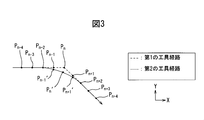
- FIG. 3 is an explanatory diagram of a tool path generation method according to the second reference example.
- the moving average is calculated by weighting each coordinate value. That is, the load average value is calculated as the corrected coordinate value.
- the coordinates (x n ′, y n ′) of each moving point after correction in consideration of the weight are calculated by the following equations (3) and (4).
- the weight to multiply the X coordinate value and the Y coordinate value of each moving point for example, the weight of the coordinate value of the moving point to be corrected is increased, and the weight is set smaller as the coordinate value of the moving point away from the moving point. be able to.
- FIG. 4 shows a graph of weights multiplied by the respective coordinate values.
- the horizontal axis indicates the movement point on the tool path. Setting is made such that the weight of the coordinate value of the movement point P n to be corrected is maximized, and the weight decreases linearly as the distance from the movement point P n increases.
- the weights shown in FIG. 4 are used for all the movement points P n-4 to P n + 4 . . That is, the same weighting pattern is adopted in correcting the coordinate values of all the moving points.
- the inward phenomenon when the moving average is calculated by multiplying the coordinate value of each moving point by the weight, the inward phenomenon can be suppressed as compared with the case of calculating the moving average without multiplying the weight.
- the inward turning phenomenon of the corrected moving point can be made smaller than in the first reference example. The influence of the coordinate value of the moving point to be corrected becomes stronger, and the corrected moving point can be brought closer to the moving point before correction.
- the formulas for calculating the corrected coordinate values can be generalized by the following formulas (5) and (6).
- the variable i is an order and can be set in advance.
- the feed shaft may be shaken or shocked.
- the surface roughness becomes rough or the dimensional accuracy decreases. That is, the processing accuracy deteriorates.
- the machining can be carried out with the moving speed of the tool 90 constant.
- the arrow 104 when the curved portion of the workpiece 91 is machined, it moves at a reduced speed.
- the speed can be restored.
- the moving speed is lowered, the processing time becomes longer.
- the moving speed and acceleration of the tool when moving on the tool path will be examined in detail.
- Fig. 5 shows an example of the tool path.
- the tool path is curved in the section from point A to point B, and the tool path is linear in the part before point A and the part after point B.
- the tool moves linearly.
- the tool moves in a curved line in the section from point A to point B.
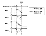
- FIG. 6 shows a graph relating to the speed and acceleration of the feed shaft.
- FIG. 6 shows the speed and acceleration of the feed axis when moving on the tool path of FIG.
- the velocity v x in the X-axis direction starts to decrease at the point A, and the velocity v x becomes zero at the point B.
- the acceleration occurs at point A, the absolute value of the acceleration is increased gradually.
- the acceleration suddenly becomes zero.
- a large change in acceleration occurs.
- the inventors have found that the cause of the change in acceleration is the change rate of the curvature of the tool path. That is, as the rate of change of curvature increases, the tool changes its traveling direction abruptly. It has been found that a large acceleration change occurs at such times. Therefore, in the tool path generation method of the present invention, a tool path that reduces the change in acceleration is generated in a portion where a large change in acceleration occurs.
- control is performed to change the weight by which the coordinates of each moving point are multiplied in accordance with the change rate of the curvature of the tool path.
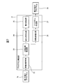
- FIG. 7 shows a block diagram of the program correction apparatus of the present embodiment.
- the program correction device 21 includes, for example, a CPU (Central Processing Unit), a RAM (Random Access Memory), a ROM (Read Only Memory), and the like connected to each other via a bus.
- a CPU Central Processing Unit
- RAM Random Access Memory
- ROM Read Only Memory
- the first machining program 76 generated in advance by the CAM device or the like is input to the program correction device 21.
- the first machining program 76 includes information on the first tool path.
- the program correction device 21 corrects the moving point of the first tool path to generate a second tool path. Then, the corrected second machining program 29 is output based on the second tool path.
- the program correction device 21 calculates a curvature at each movement point, a movement point setting unit 22 that sets a movement point based on the first machining program 76, and further calculates an intermediate curvature by correcting the curvature. Part 23.
- the program correction apparatus 21 includes a change rate calculation unit 24 that calculates the change rate of the intermediate curvature.
- the program correction device 21 includes a weight setting unit 25 that sets a weight when calculating the coordinate value of the moving average based on the calculated change rate of the intermediate curvature.
- the program correction device 21 includes a movement point correction unit 26 that corrects the movement point based on the set weight.
- the movement point correction unit 26 calculates a corrected movement point.
- the program correction device 21 also includes a program creation unit 27 that generates a new second machining program based on the corrected movement point.
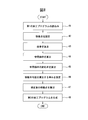
- FIG. 8 shows a flowchart of the tool path generation method in the present embodiment. This control can be performed by the program correction device 21.
- moving point setting unit 22 reads first machining program 76 created in advance.
- the movement point setting unit 22 sets a plurality of movement points in the first tool path based on the first machining program 76. More specifically, the movement point setting unit 22 sets coordinate values of a plurality of movement points.
- control device 70 performs a change rate calculation step of calculating the change rate of the curvature of the first tool path at each moving point.
- the intermediate curvature calculator 23 calculates the curvature at the moving point. The curvature is calculated for each moving point. In this embodiment, the radius of curvature at the moving point is calculated in order to calculate the curvature at the moving point.
- FIG. 9 is a diagram illustrating a method for calculating the radius of curvature.
- the radius of curvature at the movement point P n is calculated.
- the coordinate value of the moving point P n is acquired.
- the virtual circle 61 equation can be calculated. If the coordinate values of the three points are determined, the equation of the circle 61 can be calculated. Then, it is possible to set the radius of the imaginary circle 61 in the radius of curvature r n.
- FIG. 10 is a diagram illustrating another method for calculating the radius of curvature.
- a perpendicular bisector of the line segment connecting the moving point P n-1 and the moving point P n is created.
- a perpendicular bisector that connects the moving point P n and the moving point P n + 1 is created.
- a point where two vertical bisectors intersect can be set as the center point 62 of the virtual circle 61. If the coordinate value of the center point 62 is calculated, the radius of the virtual circle 61 can be calculated.
- the radius of the circle 61 can be set to the curvature radius r n at the movement point P n .
- a virtual circle In a three-dimensional coordinate system, a virtual circle can be assumed based on the coordinate values of a plurality of moving points by the same method as described above. Then, the radius of the virtual circle can be set as the curvature radius of the moving point. In addition, as a calculation method of a curvature radius, it is not restricted to this form, Arbitrary methods are employable.
- the curvature is the reciprocal of the radius of curvature. Based on the following equation (7), the curvature of the tool path at a predetermined movement point can be calculated.
- the intermediate curvature calculator 23 calculates the intermediate curvature.
- the change rate of the curvature of the tool path is calculated based on the corrected curvature.
- the corrected curvature is referred to as an intermediate curvature.
- the intermediate curvature will be described by taking the tool path shown in FIG. 5 as an example.
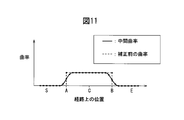
- FIG. 11 is a graph showing the curvature before correction and the intermediate curvature at the moving point.
- the curvature before correction is indicated by a broken line.
- the section from point S to point A and the section from point B to point E are zero and constant.
- the curvature before correction is constant.
- the curvature before correction increases rapidly.
- the curvature before correction is drastically decreased.
- the present embodiment corrects the smoothing process for the curvature.
- the moving average value of the curvature of a predetermined moving point can be calculated, and the calculated moving average value can be set as the intermediate curvature.
- the curvature of each moving point can be multiplied by a weight.
- FIG. 12 shows a graph of weights for calculating the moving average value of curvature.
- 10 moving points before and 10 moving points to be corrected are extracted. That is, the calculation of the 21st-order moving average value is illustrated.
- the eleventh corresponds to a moving point for calculating the current moving average value.
- a weight can be set for each moving point.
- the weight of the moving point to be corrected increases, and the weight is set to decrease as the distance from the moving point increases.
- the weight for performing the curvature smoothing process is not limited to this form, and any weight can be employed.
- the weight can be set using a normal distribution described later.
- the intermediate curvature that has been smoothed with the moving average value is shown by a solid line.
- An intermediate curvature can be calculated for each moving point. The curvature starts to increase at a position slightly before point A, and the curvature becomes constant at a position slightly after point A. In addition, the curvature starts to decrease at a position slightly before point B and becomes zero at a position slightly after point B. The curvature changes smoothly in the vicinity of the points A and B.
- change rate calculation unit 24 calculates the change rate of the intermediate curvature.
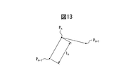
- FIG. 13 is a schematic diagram illustrating a method for calculating the change rate of the intermediate curvature.
- calculating the rate of change of the intermediate curvature at the moving point P n predetermined acquires intermediate curvature alpha n-1 intermediate curvature alpha n and the previous moving point P n-1 of the moving point P n.
- a distance l n between the movement point P n and the movement point P n ⁇ 1 is calculated.
- the rate of change in curvature of the moving point P n can be calculated by the following equation (8).
- control device 70 performs a weight calculation step of calculating the weight of the moving average based on the change rate of the curvature of the first tool path at each moving point.
- step 46 the weight setting unit 25 sets the weight for calculating the coordinate value of the moving average at each moving point. Also in the tool path generation method of the present embodiment, as in the second reference example, the corrected moving point position is set by calculating the moving average coordinate value using the weight.
- FIG. 14 shows a graph of weights when calculating the moving average coordinate values of the present embodiment.
- the graph shown in FIG. 14 illustrates a graph with a standard deviation of 1 and a graph with a standard deviation of 0.1.
- a normal distribution is used for setting the weight used for calculating the moving average.
- the horizontal axis corresponds to the moving point on the tool path.
- the vertical axis is the weight w n for calculating the coordinate value of the moving average.
- a 21st-order moving average value is calculated, and the coordinate value of the corrected moving point is calculated.
- the standard deviation is small, it can be seen the difference between the weights w n-10 in a mobile point P n-10 and weights w n at the moving point P n is large. That is, it can be seen that the smaller the standard deviation, the more concentrated the weight, and the greater the standard deviation, the more dispersed the weight.
- FIG. 15 is a graph showing the relationship between the change rate of the intermediate curvature and the standard deviation of the normal distribution for setting the weight.
- weights are distributed at moving points where the change rate of the intermediate curvature is large. That is, a normal distribution with a large standard deviation is adopted.
- a normal distribution with a small standard deviation is adopted at a moving point where the change rate of the intermediate curvature is small. In this way, control is performed to increase the standard deviation as the change rate of the intermediate curvature increases.
- the standard deviation shown in FIG. 15 can be calculated based on the following equation (9).
- the standard deviation can be calculated based on the change rate of the intermediate curvature. It should be noted that the constant a and the standard deviation minimum value ⁇ min in the equation (9) can be determined in advance by experiments or the like.
- the weight setting unit 25 can set the weight for calculating the moving average value for each moving point based on the calculation formula of Expression (9).
- the relationship between the change rate of the intermediate curvature and the standard deviation shown in FIG. 15 can be stored in advance in the storage unit. Then, the standard deviation of the normal distribution can be set based on the change rate of the intermediate curvature.
- step 47 the moving point correction unit 26 calculates the coordinate value of the corrected moving point using the set moving average weight.
- the corrected coordinate value of each moving point can be calculated based on the above-described equations (5) and (6). That is, the moving point of the second tool path can be set.
- step 48 the program creation unit 27 can generate the second machining program 29 based on the calculated position of the corrected movement point.
- a weight distribution is set for each moving point.
- a moving average coordinate value is calculated by setting a weight for each moving point, and the calculated coordinate is set as a corrected moving point.
- a weight is set using a graph with a large standard deviation.
- a large smoothing effect can be obtained in the vicinity of point A and in the vicinity of point B.
- a weight is set using a graph with a small standard deviation to reduce the smoothing effect. be able to.
- FIG. 6 shows the velocity and acceleration relating to the second tool path generated by the tool path generation method of the present embodiment in addition to the first tool path.
- a large standard deviation is adopted to distribute the weight.
- a strong smoothing effect can be obtained.
- the effect of smoothing becomes strong, the change in the curvature of the second tool path at the corrected movement point becomes gentle.
- the rate of change in acceleration is reduced.
- the acceleration a x and the acceleration a y change in acceleration in the vicinity of the neighborhood and the point B of the point A becomes smaller.
- the tool path generation method it is possible to suppress shaking and impact generated in the feed axis. Or the deceleration performed before the advancing direction of a tool path changes can be suppressed. It can be moved at a higher speed than in the prior art. For example, the machining can be performed at a speed higher than the tool path generated by the tool path generation method of the second reference example. As a result, the processing time can be shortened.
- a normal distribution is used to set a weight for calculating a moving average coordinate value.
- the degree of weight distribution can be changed by the standard deviation, and the weight distribution can be easily changed. That is, the smoothing effect can be easily adjusted.
- the standard deviation is reduced when the influence of the coordinates of the moving point to be corrected by concentrating the weight is increased. The difference between the maximum value and the minimum value of the weight increases. Also in this case, a change in weight in the vicinity of the moving point to be corrected can be reduced. In addition, a change in weight in the vicinity of the moving point farthest from the predetermined moving point can be reduced. For this reason, the change of acceleration can be made smooth.
- a distribution other than the normal distribution may be used in order to set a weight for calculating the coordinate value of the moving average.
- a distribution in which the weight changes linearly as shown in FIG. 12 may be used.
- FIG. 16 is a schematic diagram illustrating the tool path generated by the tool path generation method of the second reference example.
- a first tool path and a second tool path generated by the tool path generation method of the second reference example are shown.
- a phenomenon that the inside of the entire bending portion with respect to the input tool path appears.
- work 91 it becomes a shape smaller than a desired shape.
- FIG. 17 shows an explanatory diagram of the tool path generated by the tool path generation method of the first embodiment.
- the first tool path input to the program correction device and the second tool path generated by the tool path generation method of the present embodiment are shown.
- an inward phenomenon appears in the second tool path in order to increase the standard deviation.
- the region RC in the vicinity of the point C the influence of the coordinate value of the original moving point is increased in order to reduce the standard deviation.
- the second tool path can be made the same as the first tool path.
- a tool path that is close to the original tool path in a region where the change rate of curvature is small and away from the original tool path is generated in a region where the change of curvature is large. Is done.
- FIG. 18 shows an explanatory diagram of the tool path generated by the tool path generation method of the second embodiment.
- the second tool path overlaps the first tool path in the area RC in the vicinity of the point C, but the area RC of the second embodiment is It is much smaller than the region RC of the embodiment.
- the bent portion of the workpiece generated by the second tool path of the second embodiment has a sharper shape than the bent portion of the workpiece processed by the second tool path of the first embodiment.
- the shape of such a bent portion can be changed by changing the order used for calculating the moving average or the pitch that is the distance between the moving points.
- the order when calculating the coordinate value of the moving average is increased, it will be affected by the coordinate value of the moving point located far away. And the amount of inner rotation becomes large.
- the order is reduced, it is less likely to be affected by the coordinate values of moving points arranged far away. Therefore, when the order is reduced, a tool path in which the influence of the original movement point is increased can be generated like the tool path of the first embodiment.
- the tool path of the second embodiment with a small influence of the original moving point can be generated.
- the influence of the original coordinate value is increased by reducing the pitch, and the tool path of the first embodiment can be generated.
- the influence of the distant coordinate value is increased, and the tool path of the second embodiment can be generated.
- the tool path can be changed by increasing or decreasing the standard deviation of the normal distribution for setting the weight for all moving points.
- the tool path can be changed by changing the calculation method of the standard deviation with respect to the intermediate change rate.
- the tool path can be changed by changing the shape of the graph of FIG.
- the tool path of the first embodiment can be generated by reducing the standard deviation for all moving points.
- the tool path of the second embodiment can be generated by increasing the standard deviation for all moving points.
- the pitch between a plurality of moving points can be made variable.
- the pitch in the first tool path, the pitch can be made longer as the curvature change rate is smaller.
- the pitch By increasing the pitch in a region where the rate of change of curvature is small, the position of a distant moving point is affected. For this reason, it is possible to change the tool path before the rate of change of the curvature becomes large, and smooth the change in acceleration.
- the corrected second tool path at least a part of the area is separated from the first tool path. That is, a dimensional error occurs in the shape of the workpiece when the workpiece is processed.
- the tool path of the second embodiment has a larger workpiece dimensional error than the tool path of the first embodiment. For this reason, the dimension error of the workpiece after machining can be adjusted by changing at least one of the order, the pitch, and the standard deviation when calculating the moving average.
- the curved surface can be smoothed and the inner amount of the object increases. For this reason, the dimensional error from a design value becomes large.
- the allowable value of the dimensional error of the workpiece after machining is determined in advance.
- the number of moving points used for calculating the moving average can be set based on the allowable value of the dimensional error. For example, the maximum order in which the dimensional error is within an allowable value can be selected.
- the standard deviation of the normal distribution for setting the weight can be set based on the allowable value of the dimensional error. For example, when the dimensional error exceeds the allowable value at each moving point, the standard deviation can be set so that the dimensional error is within the allowable value.
- the pitch can be set based on the allowable value of the dimensional error. For example, it is possible to select the maximum pitch where the dimensional error is within an allowable value.
- the pitch is variable, the distance between the moving points can be set based on the allowable value of the dimensional error.
- a linear portion called a character line can be formed on the workpiece.
- the character line becomes part of the product design.
- a portion corresponding to the character line can be formed on the mold.
- the surface of the workpiece or the mold becomes smooth, while the character line is blurred.
- the tool path generation method of the present embodiment it is possible to suppress blurring of the character line.
- the second embodiment shown in FIG. 18 is particularly employed. By performing this control, the top of the bent portion can be brought close to a sharp shape, and a character line can be left.
- a character line When forming a character line, it is possible to perform control to stop the smoothing process in the vicinity of the character line. However, if the smoothing process is stopped, the surface near the character line may not be smooth. Alternatively, in the contour line machining, if there is a tool path for which the smoothing process is stopped, a step may be generated between adjacent tool paths. On the other hand, in the tool path generation method of the present embodiment, it is possible to perform a smoothing process and form a character line. Alternatively, in contour processing, a character line can be formed while avoiding the generation of a step.
- the program correction device 21 of this embodiment can be provided in a CAM device or a machine tool. Next, a machine tool provided with the program correction apparatus of this embodiment will be described.
- FIG. 19 shows a block diagram of the machine tool in the present embodiment.
- the machine tool 1 includes a control device 70.
- the control device 70 includes, for example, a CPU, a RAM, a ROM, and the like connected to each other via a bus.
- the control device 70 includes an input unit 71, a reading interpretation unit 72, an interpolation calculation unit 73, and a servo control unit 74.
- a first machining program 76 is prepared in advance.
- the first machining program 76 can be created by the CAM device 77 based on the target shape of the workpiece.
- the target shape of the workpiece can be created by, for example, a CAD (Computer Aided Design) apparatus.
- CAD Computer Aided Design
- the first machining program 76 is input to the input unit 71.
- the first machining program 76 includes information on the relative movement of the tool with respect to the workpiece.
- an operation command for the machine tool is described by a command code such as a G code or an M code.
- the first machining program may be newly created by the operator inputting characters or the like from the operation unit 81. Further, the coordinate value of the moving point may be described in the first machining program.
- the reading interpretation unit 72 reads the machining program from the input unit 71.
- the reading interpretation unit 72 sends a movement command to the interpolation calculation unit 73.
- the interpolation calculation unit 73 calculates a position command value for each interpolation cycle. For example, the interpolation calculation unit 73 calculates a movement amount for each time interval set based on the movement command.
- the interpolation calculation unit 73 sends the position command value to the servo control unit 74.
- the servo control unit 74 calculates the movement amount of each feed axis such as the X axis, Y axis, Z axis, and A axis based on the position command value, and drives each axis servo motor 75.
- the control device 70 includes an arithmetic processing unit 78 that controls machining information related to workpiece machining.
- the arithmetic processing unit 78 has a function of calculating or determining a predetermined variable based on the machining information.
- the control device 70 includes an operation unit 81 for an operator to input processing information and a display unit 82 for displaying the processing information.
- the operation unit 81 includes a keyboard and the like, and can input machining information by an operator's manual operation.
- the control device 70 includes a storage unit 80 that stores machining information.
- the storage unit 80 may be a storage device such as a memory card or a hard disk connected via a communication interface in addition to the above-described ROM and RAM.
- the arithmetic processing unit 78 includes a program correction unit 79.
- the program correction unit 79 has the function of the program correction device 21 described above. That is, the program correction unit 79 acquires the first machining program 76 from the input unit 71.
- the program correction unit 79 generates the second tool path by performing the smoothing process of the present embodiment on the first tool path.
- the program correction unit 79 generates a second machining program based on the second tool path. Then, the program correction unit 79 sends the second machining program to the input unit 71.
- the machine tool 1 drives each axis servo motor 75 based on the second program.
- machining can be performed with the tool path corrected by the tool path generation method in the present embodiment.
- the example has been described in which the tool is moved while the workpiece is stopped while the tool is moving.
- the present invention can be applied to machine tools.
Abstract
Description


21 プログラム補正装置
22 移動点設定部
23 中間曲率算出部
24 変化率算出部
25 重み設定部
26 移動点補正部
27 プログラム作成部
29 第2の加工プログラム
70 制御装置
72 読取解釈部
75 各軸サーボモータ
76 第1の加工プログラム
79 プログラム補正部
90 工具
91 ワーク DESCRIPTION OF
Claims (5)
- 工作機械にてワークを加工する第1の工具経路に対して平滑化処理を行って第2の工具経路を生成する工具経路の生成方法であって、
第1の工具経路における複数の移動点を設定する工程と、
それぞれの移動点において第1の工具経路の曲率の変化率を算出する変化率算出工程と、
それぞれの移動点において第1の工具経路の曲率の変化率に基づいて移動平均の重みを算出する重み算出工程と、
それぞれの移動点において前記重みを用いて移動点の移動平均の座標値を算出し、移動点の移動平均の座標値を第2の工具経路の移動点として設定する工程とを含むことを特徴とした、工具経路の生成方法。 A tool path generation method for generating a second tool path by performing a smoothing process on a first tool path for machining a workpiece with a machine tool,
Setting a plurality of movement points in the first tool path;
A change rate calculating step for calculating a change rate of the curvature of the first tool path at each moving point;
A weight calculating step of calculating a weight of the moving average based on the rate of change of the curvature of the first tool path at each moving point;
Calculating a moving average coordinate value of the moving point using the weight at each moving point, and setting the moving average coordinate value of the moving point as the moving point of the second tool path. A tool path generation method. - 前記変化率算出工程は、第1の工具経路のそれぞれの移動点における曲率の移動平均値を算出する工程と、
算出された曲率の移動平均値に基づいて曲率の変化率を算出する工程とを含む、請求項1に記載の工具経路の生成方法。 The change rate calculating step calculates a moving average value of curvature at each moving point of the first tool path;
The method for generating a tool path according to claim 1, further comprising: calculating a rate of change of curvature based on the calculated moving average value of curvature. - 前記重み算出工程は、曲率の変化率に基づいて正規分布の標準偏差を算出する工程と、
算出された標準偏差を有する正規分布に基づいて移動平均の前記重みを算出する工程とを含む、請求項1に記載の工具経路の生成方法。 The weight calculating step calculates a standard deviation of a normal distribution based on a change rate of curvature;
The method for generating a tool path according to claim 1, further comprising: calculating the weight of the moving average based on a normal distribution having the calculated standard deviation. - 加工後のワークの寸法誤差の許容値が予め定められており、
前記重み算出工程は、移動平均の算出に用いる移動点の個数を前記許容値に基づいて設定する工程を含む、請求項1に記載の工具経路の生成方法。 The allowable value of the dimensional error of the workpiece after machining is predetermined,
2. The tool path generation method according to claim 1, wherein the weight calculation step includes a step of setting the number of moving points used for calculating the moving average based on the allowable value. - 第1の加工プログラムにて設定される第1の工具経路に対して平滑化処理を行って第2の工具経路を作成する制御装置を備え、
前記制御装置は、第1の工具経路に基づいて複数の移動点を設定する移動点設定部と、
それぞれの移動点において第1の工具経路の曲率の変化率を算出する変化率算出部と、
それぞれの移動点において第1の工具経路の曲率の変化率に基づいて移動平均の重みを算出する重み設定部と、
それぞれの移動点において前記重みを用いて移動点の移動平均の座標値を算出し、移動点の移動平均の座標値を第2の工具経路の移動点として設定する移動点補正部と、
第2の工具経路の移動点に基づいて第2の加工プログラムを生成するプログラム作成部とを含むことを特徴とした、工作機械。 A controller that performs a smoothing process on the first tool path set by the first machining program to create a second tool path;
The control device includes a movement point setting unit that sets a plurality of movement points based on a first tool path;
A change rate calculation unit for calculating a change rate of the curvature of the first tool path at each moving point;
A weight setting unit that calculates the weight of the moving average based on the rate of change of curvature of the first tool path at each moving point;
A moving point correction unit that calculates the moving average coordinate value of the moving point using the weight at each moving point, and sets the moving average coordinate value of the moving point as the moving point of the second tool path;
A machine tool, comprising: a program creation unit configured to generate a second machining program based on a moving point of the second tool path.
Priority Applications (6)
| Application Number | Priority Date | Filing Date | Title |
|---|---|---|---|
| KR1020177009528A KR101928419B1 (en) | 2014-10-29 | 2014-10-29 | Tool Path Generation Method and Machine Tool |
| PCT/JP2014/078782 WO2016067392A1 (en) | 2014-10-29 | 2014-10-29 | Tool path generation method and machine tool |
| JP2016556104A JP6257796B2 (en) | 2014-10-29 | 2014-10-29 | Tool path generation method and machine tool |
| EP14905198.9A EP3214515B1 (en) | 2014-10-29 | 2014-10-29 | Tool path generation method and machine tool |
| US15/517,455 US10248101B2 (en) | 2014-10-29 | 2014-10-29 | Tool path generation method and machine tool using rate of change of curvature based smoothing |
| CN201480082916.4A CN107077126B (en) | 2014-10-29 | 2014-10-29 | The generation method and lathe of cutter path |
Applications Claiming Priority (1)
| Application Number | Priority Date | Filing Date | Title |
|---|---|---|---|
| PCT/JP2014/078782 WO2016067392A1 (en) | 2014-10-29 | 2014-10-29 | Tool path generation method and machine tool |
Publications (1)
| Publication Number | Publication Date |
|---|---|
| WO2016067392A1 true WO2016067392A1 (en) | 2016-05-06 |
Family
ID=55856778
Family Applications (1)
| Application Number | Title | Priority Date | Filing Date |
|---|---|---|---|
| PCT/JP2014/078782 WO2016067392A1 (en) | 2014-10-29 | 2014-10-29 | Tool path generation method and machine tool |
Country Status (6)
| Country | Link |
|---|---|
| US (1) | US10248101B2 (en) |
| EP (1) | EP3214515B1 (en) |
| JP (1) | JP6257796B2 (en) |
| KR (1) | KR101928419B1 (en) |
| CN (1) | CN107077126B (en) |
| WO (1) | WO2016067392A1 (en) |
Cited By (7)
| Publication number | Priority date | Publication date | Assignee | Title |
|---|---|---|---|---|
| WO2017113195A1 (en) * | 2015-12-30 | 2017-07-06 | 深圳配天智能技术研究院有限公司 | Processing path planning method, processing path planning apparatus and numerically controlled machine tool |
| CN109725600A (en) * | 2017-10-30 | 2019-05-07 | 发那科株式会社 | Preprocessor device, processing program generation method, CNC system of processing and computer-readable information recording medium |
| WO2020110251A1 (en) * | 2018-11-29 | 2020-06-04 | 三菱電機株式会社 | Numerical control device, numerical control method, and machine learning device |
| WO2021230237A1 (en) * | 2020-05-14 | 2021-11-18 | ファナック株式会社 | Processing path creation device |
| WO2023058243A1 (en) * | 2021-10-08 | 2023-04-13 | ファナック株式会社 | Control device and computer-readable recording medium storing program |
| US11644813B2 (en) | 2017-10-30 | 2023-05-09 | Fanuc Corporation | Numerical controller, CNC machine tool, numerical control method, and computer-readable information storage medium |
| JP7355951B1 (en) * | 2022-08-23 | 2023-10-03 | ファナック株式会社 | Control device and computer readable recording medium |
Families Citing this family (8)
| Publication number | Priority date | Publication date | Assignee | Title |
|---|---|---|---|---|
| US10151643B2 (en) * | 2016-08-22 | 2018-12-11 | The Boeing Company | Thermal event indicator for aircraft engine |
| DE112017004424T5 (en) * | 2016-09-02 | 2019-06-19 | Mitsubishi Electric Corporation | Command value generation device |
| KR102441054B1 (en) * | 2016-11-23 | 2022-09-06 | 현대자동차주식회사 | Apparatus and method for controlling path of vehicle |
| CN111837080B (en) * | 2018-03-09 | 2023-05-23 | 株式会社牧野铣床制作所 | Tool path generation method |
| KR102347462B1 (en) | 2020-08-03 | 2022-01-04 | 단국대학교 산학협력단 | Tool path smoothing method for machine tools |
| CN112256030B (en) * | 2020-10-20 | 2021-06-15 | 乐聚(深圳)机器人技术有限公司 | Footprint generation method and device for robot, robot and medium |
| CN114603430B (en) * | 2022-05-10 | 2022-08-19 | 中国科学院光电技术研究所 | Method for inhibiting surface band-breaking errors of deep axicon optical element |
| CN114942615B (en) * | 2022-05-23 | 2023-07-28 | 江南大学 | Equal-bow-height error interpolation method, device and storage medium |
Citations (3)
| Publication number | Priority date | Publication date | Assignee | Title |
|---|---|---|---|---|
| JPS6436308A (en) * | 1987-07-31 | 1989-02-07 | Okuma Machinery Works Ltd | Numeric value control system |
| JP2007257094A (en) * | 2006-03-22 | 2007-10-04 | Toyota Motor Corp | Method for creating path, moving element and moving element control system |
| WO2012056588A1 (en) * | 2010-10-26 | 2012-05-03 | 株式会社牧野フライス製作所 | Method and device for generating tool path |
Family Cites Families (12)
| Publication number | Priority date | Publication date | Assignee | Title |
|---|---|---|---|---|
| US3969615A (en) * | 1974-12-20 | 1976-07-13 | The United States Of America As Represented By The United States Energy Research And Development Administration | Interpolator for numerically controlled machine tools |
| US6591158B1 (en) * | 2000-06-09 | 2003-07-08 | The Boeing Company | Methods and apparatus for defining a low-curvature tool path |
| JP3958112B2 (en) | 2002-05-20 | 2007-08-15 | ファナック株式会社 | Speed control method in numerical controller |
| JP4972447B2 (en) | 2007-04-06 | 2012-07-11 | オークマ株式会社 | Numerical controller |
| JP2011096077A (en) * | 2009-10-30 | 2011-05-12 | Makino Milling Mach Co Ltd | Method and device for generating tool path |
| WO2012056554A1 (en) | 2010-10-25 | 2012-05-03 | 株式会社牧野フライス製作所 | Tool path generation method and tool path generation device |
| WO2012057235A1 (en) * | 2010-10-27 | 2012-05-03 | 株式会社牧野フライス製作所 | Numerical control method |
| JP5417392B2 (en) * | 2011-07-29 | 2014-02-12 | 新日本工機株式会社 | Numerical controller |
| JP5911595B2 (en) * | 2012-10-31 | 2016-04-27 | 株式会社牧野フライス製作所 | Machine tool control device and machine tool |
| CN103809510B (en) | 2012-11-09 | 2016-06-15 | 沈阳高精数控技术有限公司 | A kind of towards high accurately machined free form surface reciprocating cutting tool method for planning track |
| CN103744349B (en) | 2013-10-08 | 2016-04-20 | 华中科技大学 | A kind of Non intrusive method generation method of square end mill processing fillet surface |
| JP7060341B2 (en) | 2017-06-28 | 2022-04-26 | Jfe建材株式会社 | Compression device and collapse prevention device |
-
2014
- 2014-10-29 WO PCT/JP2014/078782 patent/WO2016067392A1/en active Application Filing
- 2014-10-29 JP JP2016556104A patent/JP6257796B2/en not_active Expired - Fee Related
- 2014-10-29 CN CN201480082916.4A patent/CN107077126B/en not_active Expired - Fee Related
- 2014-10-29 KR KR1020177009528A patent/KR101928419B1/en active IP Right Grant
- 2014-10-29 EP EP14905198.9A patent/EP3214515B1/en not_active Not-in-force
- 2014-10-29 US US15/517,455 patent/US10248101B2/en not_active Expired - Fee Related
Patent Citations (3)
| Publication number | Priority date | Publication date | Assignee | Title |
|---|---|---|---|---|
| JPS6436308A (en) * | 1987-07-31 | 1989-02-07 | Okuma Machinery Works Ltd | Numeric value control system |
| JP2007257094A (en) * | 2006-03-22 | 2007-10-04 | Toyota Motor Corp | Method for creating path, moving element and moving element control system |
| WO2012056588A1 (en) * | 2010-10-26 | 2012-05-03 | 株式会社牧野フライス製作所 | Method and device for generating tool path |
Cited By (16)
| Publication number | Priority date | Publication date | Assignee | Title |
|---|---|---|---|---|
| WO2017113195A1 (en) * | 2015-12-30 | 2017-07-06 | 深圳配天智能技术研究院有限公司 | Processing path planning method, processing path planning apparatus and numerically controlled machine tool |
| US11644813B2 (en) | 2017-10-30 | 2023-05-09 | Fanuc Corporation | Numerical controller, CNC machine tool, numerical control method, and computer-readable information storage medium |
| CN109725600A (en) * | 2017-10-30 | 2019-05-07 | 发那科株式会社 | Preprocessor device, processing program generation method, CNC system of processing and computer-readable information recording medium |
| JP2019082852A (en) * | 2017-10-30 | 2019-05-30 | ファナック株式会社 | Postprocessor device, processing program generation method, cnc machining system, and program for processing program generation |
| US11681274B2 (en) | 2017-10-30 | 2023-06-20 | Fanuc Corporation | Postprocessor device that generates a machining program including instruction for changing at least one parameter to be used for controlling at least one axis of a CNC machine tool |
| CN109725600B (en) * | 2017-10-30 | 2021-04-13 | 发那科株式会社 | Post-processor device, machining program generating method, CNC machining system, and computer-readable information recording medium |
| JP6740483B1 (en) * | 2018-11-29 | 2020-08-12 | 三菱電機株式会社 | Numerical control device and numerical control method |
| US11131979B2 (en) | 2018-11-29 | 2021-09-28 | Mitsubishi Electric Corporation | Numerical control device and numerical control method |
| CN113168155B (en) * | 2018-11-29 | 2022-05-13 | 三菱电机株式会社 | Numerical control device and numerical control method |
| CN113168155A (en) * | 2018-11-29 | 2021-07-23 | 三菱电机株式会社 | Numerical control device, numerical control method, and machine learning device |
| WO2020110251A1 (en) * | 2018-11-29 | 2020-06-04 | 三菱電機株式会社 | Numerical control device, numerical control method, and machine learning device |
| WO2021230237A1 (en) * | 2020-05-14 | 2021-11-18 | ファナック株式会社 | Processing path creation device |
| JP7428793B2 (en) | 2020-05-14 | 2024-02-06 | ファナック株式会社 | Machining path creation device |
| WO2023058243A1 (en) * | 2021-10-08 | 2023-04-13 | ファナック株式会社 | Control device and computer-readable recording medium storing program |
| JP7355951B1 (en) * | 2022-08-23 | 2023-10-03 | ファナック株式会社 | Control device and computer readable recording medium |
| WO2024042617A1 (en) * | 2022-08-23 | 2024-02-29 | ファナック株式会社 | Control device and computer-readable recording medium |
Also Published As
| Publication number | Publication date |
|---|---|
| EP3214515B1 (en) | 2019-10-23 |
| CN107077126B (en) | 2019-06-14 |
| KR101928419B1 (en) | 2018-12-12 |
| EP3214515A1 (en) | 2017-09-06 |
| US20170300029A1 (en) | 2017-10-19 |
| EP3214515A4 (en) | 2018-08-01 |
| KR20170053690A (en) | 2017-05-16 |
| US10248101B2 (en) | 2019-04-02 |
| JPWO2016067392A1 (en) | 2017-05-18 |
| CN107077126A (en) | 2017-08-18 |
| JP6257796B2 (en) | 2018-01-10 |
Similar Documents
| Publication | Publication Date | Title |
|---|---|---|
| JP6257796B2 (en) | Tool path generation method and machine tool | |
| WO2011052800A1 (en) | Tool path generation method and device | |
| JP5762625B2 (en) | Trajectory control device | |
| JP5615377B2 (en) | Tool path generation method and generation apparatus | |
| US10481567B2 (en) | Gear tooth profile simulation apparatus and method, and machining tool edge surface simulation apparatus and method | |
| JP6684962B2 (en) | Tool path generation method and device | |
| JP2013030102A (en) | Numerical control device | |
| JP6548830B2 (en) | Command value generator | |
| CN109597359B (en) | Numerical controller | |
| CN111770829A (en) | Method and system for additive manufacturing | |
| JP4702951B2 (en) | Contour surface and solid processing method with numerically controlled single blade | |
| US10037021B2 (en) | Numerical controller performing speed control with curvature and curvature change amount | |
| JP6038331B2 (en) | Tool path generation method and tool path generation apparatus | |
| JP5705355B1 (en) | Wall part machining method and tool path generation device | |
| US10877457B2 (en) | Method for providing a travel profile, control device, machine, and computer program | |
| JP6340382B2 (en) | Processing method using laser blanking equipment | |
| JP4517156B2 (en) | Method for calculating uneven shape of cutting surface in milling and processing control method for uneven shape | |
| WO2016199266A1 (en) | Numerical value control device | |
| JP3903779B2 (en) | Determination method of tool diameter and machining layer in contour machining | |
| JP6844772B2 (en) | Grinding device and grinding method | |
| JP2007061934A (en) | Moving path creating method of machining tool and machining method |
Legal Events
| Date | Code | Title | Description |
|---|---|---|---|
| 121 | Ep: the epo has been informed by wipo that ep was designated in this application |
Ref document number: 14905198 Country of ref document: EP Kind code of ref document: A1 |
|
| ENP | Entry into the national phase |
Ref document number: 2016556104 Country of ref document: JP Kind code of ref document: A |
|
| WWE | Wipo information: entry into national phase |
Ref document number: 15517455 Country of ref document: US |
|
| REEP | Request for entry into the european phase |
Ref document number: 2014905198 Country of ref document: EP |
|
| NENP | Non-entry into the national phase |
Ref country code: DE |